KR100218143B1 - Tempered Glass Manufacturing Equipment - Google Patents
Tempered Glass Manufacturing EquipmentDownload PDFInfo
- Publication number
- KR100218143B1 KR100218143B1KR1019970012906AKR19970012906AKR100218143B1KR 100218143 B1KR100218143 B1KR 100218143B1KR 1019970012906 AKR1019970012906 AKR 1019970012906AKR 19970012906 AKR19970012906 AKR 19970012906AKR 100218143 B1KR100218143 B1KR 100218143B1
- Authority
- KR
- South Korea
- Prior art keywords
- tempered glass
- conveyor
- heating chamber
- upper mold
- cooling
- Prior art date
- Legal status (The legal status is an assumption and is not a legal conclusion. Google has not performed a legal analysis and makes no representation as to the accuracy of the status listed.)
- Expired - Fee Related
Links
Images


Classifications
- C—CHEMISTRY; METALLURGY
- C03—GLASS; MINERAL OR SLAG WOOL
- C03B—MANUFACTURE, SHAPING, OR SUPPLEMENTARY PROCESSES
- C03B27/00—Tempering or quenching glass products
- C03B27/04—Tempering or quenching glass products using gas
- C—CHEMISTRY; METALLURGY
- C03—GLASS; MINERAL OR SLAG WOOL
- C03B—MANUFACTURE, SHAPING, OR SUPPLEMENTARY PROCESSES
- C03B23/00—Re-forming shaped glass
- C03B23/02—Re-forming glass sheets
- C03B23/023—Re-forming glass sheets by bending
- C03B23/03—Re-forming glass sheets by bending by press-bending between shaping moulds
- C—CHEMISTRY; METALLURGY
- C03—GLASS; MINERAL OR SLAG WOOL
- C03B—MANUFACTURE, SHAPING, OR SUPPLEMENTARY PROCESSES
- C03B35/00—Transporting of glass products during their manufacture, e.g. hot glass lenses, prisms
- C03B35/04—Transporting of hot hollow or semi-hollow glass products
- C—CHEMISTRY; METALLURGY
- C03—GLASS; MINERAL OR SLAG WOOL
- C03B—MANUFACTURE, SHAPING, OR SUPPLEMENTARY PROCESSES
- C03B35/00—Transporting of glass products during their manufacture, e.g. hot glass lenses, prisms
- C03B35/14—Transporting hot glass sheets or ribbons, e.g. by heat-resistant conveyor belts or bands
- C03B35/145—Transporting hot glass sheets or ribbons, e.g. by heat-resistant conveyor belts or bands by top-side transfer or supporting devices, e.g. lifting or conveying using suction
Landscapes
- Chemical & Material Sciences (AREA)
- Engineering & Computer Science (AREA)
- Materials Engineering (AREA)
- Organic Chemistry (AREA)
- Physics & Mathematics (AREA)
- Thermal Sciences (AREA)
- Re-Forming, After-Treatment, Cutting And Transporting Of Glass Products (AREA)
Abstract
Translated fromKoreanDescription
Translated fromKorean본 발명은 강화유리 제조장치에 관한 것이며, 상세하게는 판유리를 열처리하여 강화할 때 노와 냉각수단 사이에 성형수단을 구비한 강화유리 제조장치에 관한 것이다. 주지하는 바와 같이 강화유리는 판유리를 열처리(뜨임)하여 유리의 표면에 압축응력을 가한 것이므로 판유리에 비하여 압력, 온도변화에 대한 강도가 수배나 크게 되므로 만일 깨어진다 하여도 작은 둥근 모양의 알맹이가 되기 때문에 파편에 대한 위험성이 적어서 자동차, 빌딩 또는 상점의 도어, 조리용기 등에 널리 사용되고 있다. 상기한 강화유리는 판유리를 노에서 650 ~ 900℃ 내외로 가열한 후 냉각수단에 의하여 급속히 공냉하는 것인 바, 소요형상으로 절단된 판유리를 회전식 노에서 가열한 후 이송수단에 의하여 냉각수단으로 이송하여 가열된 판유리의 상하에서 에어노즐에 의하여 공기를 분사시켜 유리의 표면온도를 200℃ 내지 425℃ 정도까지 냉각시키는 것이며, 필요한 용도에 따라 냉각공정전에 성형수단에 의하여 일정한 형상으로 성형한 후 냉각수단으로 운반 급냉하는 것이다.The present invention relates to a tempered glass manufacturing apparatus, and more particularly, to a tempered glass manufacturing apparatus having a forming means between the furnace and the cooling means when heat-treating the plate glass. As it is known, tempered glass is heat treated (tempered) and applied compressive stress to the surface of the glass. Therefore, the strength against pressure and temperature change is many times higher than that of glass, so it becomes a small round-shaped kernel even if it breaks. Because of the low risk of debris is widely used in cars, buildings or shop doors, cooking vessels. The tempered glass is to heat the plate glass to about 650 ~ 900 ℃ in the furnace and then rapidly air-cooled by the cooling means, the plate glass cut into the required shape is heated in the rotary furnace and then transferred to the cooling means by the transfer means. Air is sprayed by an air nozzle on the upper and lower sides of the heated plate glass to cool the surface temperature of the glass to about 200 ° C to 425 ° C. To be quenched to carry.
종래의 강화유리 제조장치는 제1도 및 제2도에서 참조되는 바와 같이 노본체(1)에 콘베어(2)를 설치하여 클러치가 설치된 구동수단(미도시)에 의하여 가열실(3) 내를 회전 이동하도록 하고, 상기 콘베어(2)에 받침부재 겸 하부 금형(5)을 설치하며, 가열실(3)의 일부를 절단하여 형성한 소재 삽입부 겸 인출부(4)에서 상기 받침부재 겸 하부 금형(5)에 판유리를 일정형상으로 절단한 소재를 재치하고 콘베어(2)를 화살표 방향으로 회전시키면서 가열실(3) 내에서 650 ~ 900℃ 내외로 가열하여서 소재 삽입부 겸 인출부(4)에 되돌아오게 하며, 상기 소재 삽입부 겸 인출부(4)에 노본체(1)의 반경방향으로 이동할 수 있는 상부 금형(5')을 설치하여 가열된 소재가 하부 금형(5)에 이송되었을 때 구동수단의 클러치를 분리하여 콘베어(2)의 회전을 중단한 후 상부 금형(5')을 하강시켜 일정형상으로 성형하는 것이다.In the conventional tempered glass manufacturing apparatus, as shown in FIGS. 1 and 2, the
상기와 같이 성형된 반제품은 상부 금형(5')에 부착된 상태로 전도기구(8)에 의하여 이송판(7) 상에 운반된 후 수평 이송기구(14)에 의하여 콘베어(16) 상으로 운반되고 콘베어(16)의 상하에 설치된 냉각수단(에어 노즐)(17)에서 분사되는 공기에 의하여 급냉되어서 강화되는 것이다.The semi-finished product shaped as described above is conveyed onto the
그러나 상기한 강화유리 제조장치는 가열실(3) 내에서 가열된 소재가 소재 삽입부 겸 인출부(4)에 되돌아오면 대기상태에 노출되고 대기상태에 노출된 상부 금형(5')에 의하여 성형될 때 판유리 소재 및 반제품이 냉각되며, 전도기구(8)와 수평 이송기구(14)에 의하여 콘베어(16)에 운반되는 과정에서 냉각되어서 서냉되기 때문에 강화가 불완전하게 되어서 강도가 작아지므로 안전성이 낮아지는 문제점이 있는 것이다.However, the above-mentioned tempered glass manufacturing apparatus is formed by the upper mold 5 'exposed to the atmospheric state and exposed to the atmospheric state when the material heated in the heating chamber 3 returns to the material inserting and extracting part 4. When the plate glass material and semi-finished product is cooled, it is cooled in the process of being conveyed to the
본 발명은 상기한 문제점을 시정하여 가열된 소재를 성형할 때 냉각되는 것을 방지하여 강도가 작아지는 것을 억제하므로서 안전성을 증대시킨 강화유리 제조장치를 제공하는 것을 목적으로 한다.SUMMARY OF THE INVENTION An object of the present invention is to provide a tempered glass manufacturing apparatus which increases safety while preventing the cooling by molding the heated material to prevent cooling and thus reducing the strength.
상기한 목적을 달성하기 위하여 본 발명은 노본체에 가열실내를 회전하는 콘베어를 설치하여 받침부재 겸 하부 금형을 설치하고, 가열실의 일부를 절단하여 형성한 소재 삽입부 겸 인출부에 상부 금형을 설치하며, 상기 소재 삽입부 겸 인출부의 인접위치에 이송판과 냉각수단을 설치한 것에 있어서, 상기 상부 금형에 히터를 설치하여 받침부재 겸 하부 금형에 재치된 소재를 성형할 때 냉각되는 것을 방지토록 한 것이다.In order to achieve the above object, the present invention is to install a bearing member and a lower mold by installing a conveyor for rotating the inside of the heating chamber in the furnace body, and the upper mold is inserted into the material inserting and extracting part formed by cutting a part of the heating chamber. And a conveying plate and a cooling means provided at an adjacent position of the material inserting part and the drawing part, wherein a heater is installed on the upper mold to prevent cooling when forming the material placed on the supporting member and the lower mold. It is.
제1도는 본 발명의 실시예의 사시도.1 is a perspective view of an embodiment of the present invention.
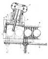
제2도는 본 발명의 실시예의 일부 절단 요부 평면도.2 is a plan view of a part of a cutting portion of an embodiment of the present invention.
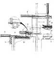
제3도는 본 발명의 실시예의 요부 절단 측면도.3 is a side view of the main portion cut in the embodiment of the present invention.
제4도는 본 발명의 실시예의 상부 금형의 분해 사시도.4 is an exploded perspective view of the upper mold of the embodiment of the present invention.
* 도면의 주요부분에 대한 부호의 설명* Explanation of symbols for main parts of the drawings
1 : 노본체 2 : 콘베어1: main body 2: conveyor
3 : 가열실 4 : 소재 삽입부 겸 인출부3: heating chamber 4: material insertion part and withdrawal part
5 : 받침부재 겸 하부 금형 5' : 상부 금형5: Support member and lower mold 5 ': Upper mold
7 : 이송판 8 : 전도기구7
14 : 수평 이송기구 17 : 냉각수단14
18 : 히터 20 : 가열수단18: heater 20: heating means
본 발명은 제1도 내지 제4도에 도시한 바와 같이 노본체(1)에 콘베어(2)를 설치하여 클러치가 설치된 구동수단(미도시)에 의하여 가열실(3)내를 회전 이동토록하고, 상기 콘베어(2)에 받침부재 겸 하부 금형(5)을 설치하며, 가열실(3)의 일부를 절단하여 형성한 소재 삽입부 겸 인출부(4)에서 상기 받침부재 겸 하부 금형(5)에 판유리를 일정형상으로 절단한 소재를 재치하고 콘베어(2)를 화살표 방향으로 회전시키면서 소재를 가열실(3)에서 가열하여서 소재 삽입부 겸 인출부(4)로 되돌아오게 하며, 상기 소재 삽입부 겸 인출부(4)에 수직 공압 실린더(6)에 의하여 승강되고 수평 공압 실린더(6')에 의하여 노본체(1)의 반경방향으로 이동할 수 있는 상부 금형(5')을 설치하고, 상기 소재 삽입부 겸 인출부(4)의 인접위치에 이송판(7)을 설치하여 그 전방에 공압 실린더(9)에 의하여 직선왕복 운동하는 랙기어(10)를 설치하고 상기 랙기어(10)에 치합되는 피니온(12)이 일단에 형성된 지지축(11)을 설치하여 받침부재(13)를 설치한 전도기구(8)를 설치하며, 상기 이송판(7)의 전방에 공압 실린더(15)(15')에 의하여 전후 좌우로 수평 이동하는 이송기구(14)를 설치하며, 상기 이송판(7)의 측면에 콘베어(16)를 설치함과 동시에 그 상하에 콘베어(16)를 따라 이송하는 반제품에 압축공기를 분사하는 냉각수단(에어 노즐)(17)을 설치한 것이다.The present invention, as shown in Figures 1 to 4, by installing the conveyor (2) in the furnace
그리고 상기 상부 금형(5')에는 히터(18)를 내장함과 동시에 소재를 성형한 후 받침부재(13)에 이송할 때 소재가 하부 금형(5)에 부착된 상태를 유지하도록 진공펌프(미도시)와 연결되는 진공 흡입공(19)을 형성하고, 이송판(7)에 가열수단(20)을 설치하여서 된 것이다.In addition, the
이상과 같은 본 발명은 소재 삽입부 겸 인출부(4)의 일측에서 받침부재 겸 하부 금형(5)에 소재를 재치하고 콘베어(2)를 회전시키면 가열실(3)에서 소재가 가열되고 소재 삽입부 겸 인출부(4)의 타측으로 되돌아오게 한 후 상하부 금형(5')(5)이 일치된 위치에서 콘베어(2)의 회전을 중단하고 수직 공압 실린더(6)를 하강하여 소재를 가압하여 일정형상으로 성형하며, 상기와 같이 소재가 성형될 때 상부 금형(5')은 히터(18)에 의하여 가열된 상태를 유지하고 있으므로 소재 및 반제품이 냉각되는 것이 방지되는 것이다.In the present invention as described above, when the material is placed in the supporting member and the
상기한 바와 같이 반제품을 성형한 후 수직 공압 실린더(6)를 상승시키고 수평 공압 실린더(6')를 후진하여 반제품을 전도기구(8)에 의하여 이송판(7)에 이송하는 것이며, 이 때 하부 금형(5')에 형성한 진공 흡입공(19)은 진공펌프에 의하여 부압이 형성되므로 반제품은 하부 금형(5')에 부착된 상태로 이송되는 것이다.After forming the semi-finished product as described above, the vertical
상기와 같이 이송판(7)에 이송된 반제품은 이송기구(14)에 의하여 콘베어(16)로 운반되며, 이 때 이송판(7)에는 가열수단(20)이 설치되어 있으므로 대기와 노출된 상태를 유지하면서도 반제품의 냉각이 억제되면서 콘베어(16)로 운반되는 것이다.As described above, the semi-finished product conveyed to the
이상과 같이 본 발명은 가열된 소재를 성형할 때 소재 및 반제품이 냉각되는 것을 방지하여 강도가 작아지는 것을 억제하므로서 안전성이 증대되며, 성형 후 냉각수단으로 이송할 때에도 서냉을 방지하므로서 냉각수단에서의 급냉효과가 증대되어 안전성이 증대되는 효과 등이 있는 것이다.As described above, the present invention increases the safety by preventing the material and the semi-finished product from being cooled when molding the heated material, thereby suppressing the decrease in strength, and prevents slow cooling even when transferring to the cooling means after the molding. There is an effect that the quenching effect is increased to increase the safety.
Claims (2)
Translated fromKoreanPriority Applications (1)
| Application Number | Priority Date | Filing Date | Title |
|---|---|---|---|
| KR1019970012906AKR100218143B1 (en) | 1997-04-08 | 1997-04-08 | Tempered Glass Manufacturing Equipment |
Applications Claiming Priority (1)
| Application Number | Priority Date | Filing Date | Title |
|---|---|---|---|
| KR1019970012906AKR100218143B1 (en) | 1997-04-08 | 1997-04-08 | Tempered Glass Manufacturing Equipment |
Publications (2)
| Publication Number | Publication Date |
|---|---|
| KR19980076263A KR19980076263A (en) | 1998-11-16 |
| KR100218143B1true KR100218143B1 (en) | 1999-09-01 |
Family
ID=19502196
Family Applications (1)
| Application Number | Title | Priority Date | Filing Date |
|---|---|---|---|
| KR1019970012906AExpired - Fee RelatedKR100218143B1 (en) | 1997-04-08 | 1997-04-08 | Tempered Glass Manufacturing Equipment |
Country Status (1)
| Country | Link |
|---|---|
| KR (1) | KR100218143B1 (en) |
Cited By (10)
| Publication number | Priority date | Publication date | Assignee | Title |
|---|---|---|---|---|
| US9296638B2 (en) | 2014-07-31 | 2016-03-29 | Corning Incorporated | Thermally tempered glass and methods and apparatuses for thermal tempering of glass |
| US10611664B2 (en) | 2014-07-31 | 2020-04-07 | Corning Incorporated | Thermally strengthened architectural glass and related systems and methods |
| US11097974B2 (en) | 2014-07-31 | 2021-08-24 | Corning Incorporated | Thermally strengthened consumer electronic glass and related systems and methods |
| US11485673B2 (en) | 2017-08-24 | 2022-11-01 | Corning Incorporated | Glasses with improved tempering capabilities |
| US11643355B2 (en) | 2016-01-12 | 2023-05-09 | Corning Incorporated | Thin thermally and chemically strengthened glass-based articles |
| US11697617B2 (en) | 2019-08-06 | 2023-07-11 | Corning Incorporated | Glass laminate with buried stress spikes to arrest cracks and methods of making the same |
| US11708296B2 (en) | 2017-11-30 | 2023-07-25 | Corning Incorporated | Non-iox glasses with high coefficient of thermal expansion and preferential fracture behavior for thermal tempering |
| US11795102B2 (en) | 2016-01-26 | 2023-10-24 | Corning Incorporated | Non-contact coated glass and related coating system and method |
| US12064938B2 (en) | 2019-04-23 | 2024-08-20 | Corning Incorporated | Glass laminates having determined stress profiles and methods of making the same |
| US12338159B2 (en) | 2015-07-30 | 2025-06-24 | Corning Incorporated | Thermally strengthened consumer electronic glass and related systems and methods |
- 1997
- 1997-04-08KRKR1019970012906Apatent/KR100218143B1/ennot_activeExpired - Fee Related
Cited By (20)
| Publication number | Priority date | Publication date | Assignee | Title |
|---|---|---|---|---|
| US11891324B2 (en) | 2014-07-31 | 2024-02-06 | Corning Incorporated | Thermally strengthened consumer electronic glass and related systems and methods |
| US9776905B2 (en) | 2014-07-31 | 2017-10-03 | Corning Incorporated | Highly strengthened glass article |
| US9783448B2 (en) | 2014-07-31 | 2017-10-10 | Corning Incorporated | Thin dicing glass article |
| US9802853B2 (en) | 2014-07-31 | 2017-10-31 | Corning Incorporated | Fictive temperature in damage-resistant glass having improved mechanical characteristics |
| US9975801B2 (en) | 2014-07-31 | 2018-05-22 | Corning Incorporated | High strength glass having improved mechanical characteristics |
| US10005691B2 (en) | 2014-07-31 | 2018-06-26 | Corning Incorporated | Damage resistant glass article |
| US10077204B2 (en) | 2014-07-31 | 2018-09-18 | Corning Incorporated | Thin safety glass having improved mechanical characteristics |
| US10233111B2 (en) | 2014-07-31 | 2019-03-19 | Corning Incorporated | Thermally tempered glass and methods and apparatuses for thermal tempering of glass |
| US11097974B2 (en) | 2014-07-31 | 2021-08-24 | Corning Incorporated | Thermally strengthened consumer electronic glass and related systems and methods |
| US10611664B2 (en) | 2014-07-31 | 2020-04-07 | Corning Incorporated | Thermally strengthened architectural glass and related systems and methods |
| US9296638B2 (en) | 2014-07-31 | 2016-03-29 | Corning Incorporated | Thermally tempered glass and methods and apparatuses for thermal tempering of glass |
| US12338159B2 (en) | 2015-07-30 | 2025-06-24 | Corning Incorporated | Thermally strengthened consumer electronic glass and related systems and methods |
| US11643355B2 (en) | 2016-01-12 | 2023-05-09 | Corning Incorporated | Thin thermally and chemically strengthened glass-based articles |
| US11795102B2 (en) | 2016-01-26 | 2023-10-24 | Corning Incorporated | Non-contact coated glass and related coating system and method |
| US11485673B2 (en) | 2017-08-24 | 2022-11-01 | Corning Incorporated | Glasses with improved tempering capabilities |
| US11708296B2 (en) | 2017-11-30 | 2023-07-25 | Corning Incorporated | Non-iox glasses with high coefficient of thermal expansion and preferential fracture behavior for thermal tempering |
| US12410090B2 (en) | 2017-11-30 | 2025-09-09 | Corning Incorporated | Non-iox glasses with high coefficient of thermal expansion and preferential fracture behavior for thermal tempering |
| US12064938B2 (en) | 2019-04-23 | 2024-08-20 | Corning Incorporated | Glass laminates having determined stress profiles and methods of making the same |
| US11697617B2 (en) | 2019-08-06 | 2023-07-11 | Corning Incorporated | Glass laminate with buried stress spikes to arrest cracks and methods of making the same |
| US12043575B2 (en) | 2019-08-06 | 2024-07-23 | Corning Incorporated | Glass laminate with buried stress spikes to arrest cracks and methods of making the same |
Also Published As
| Publication number | Publication date |
|---|---|
| KR19980076263A (en) | 1998-11-16 |
Similar Documents
| Publication | Publication Date | Title |
|---|---|---|
| KR100218143B1 (en) | Tempered Glass Manufacturing Equipment | |
| US7401476B2 (en) | Method and apparatus for bending a glass sheet | |
| KR100292561B1 (en) | Curved Glass Products Manufacturing Equipment | |
| KR100367539B1 (en) | Method and apparatus for bending and tempering glass plates | |
| US4661141A (en) | Glass sheet press bending system | |
| KR900005386B1 (en) | Glass sheet press bending system | |
| US4297121A (en) | Glass tempering furnaces and systems | |
| KR101627503B1 (en) | Transfer Unit For High Temperature And Vacuum Heat Treatment Furnace | |
| US4285715A (en) | Cycle of mold movement while press bending glass sheets | |
| KR101149306B1 (en) | Apparatus for manufacturing a tempered glass | |
| JPH07267663A (en) | Heat softening plate material forming apparatus and method | |
| US4187095A (en) | Method and apparatus for handling glass sheets during shaping and cooling | |
| KR970006991B1 (en) | Method and apparatus of bending glass sheets | |
| US5340375A (en) | Method and apparatus for bending and tempering a glass sheet | |
| US5735923A (en) | Method of and apparatus for cooling and tempering a glass plate | |
| US4185986A (en) | Apparatus for handling glass sheets during shaping and cooling | |
| US20030182969A1 (en) | Glass handling and locating system | |
| JP3598538B2 (en) | Method and apparatus for quenching and strengthening glass plate | |
| KR100362306B1 (en) | Manufacturing method and device for strengthening glass with 3rd dimension curved surface | |
| JPS5919890B2 (en) | Glass plate processing equipment | |
| CN209065740U (en) | A kind of glass production annealing furnace | |
| US4331464A (en) | Glass sheet support of ring-like configuration | |
| CN210267943U (en) | Automatic heating control device | |
| AU693849B2 (en) | Bending glass sheets | |
| JP2006093084A (en) | Molding system of lamp upper plate of flat plate type fluorescent lamp |
Legal Events
| Date | Code | Title | Description |
|---|---|---|---|
| A201 | Request for examination | ||
| PA0109 | Patent application | St.27 status event code:A-0-1-A10-A12-nap-PA0109 | |
| PA0201 | Request for examination | St.27 status event code:A-1-2-D10-D11-exm-PA0201 | |
| R17-X000 | Change to representative recorded | St.27 status event code:A-3-3-R10-R17-oth-X000 | |
| PG1501 | Laying open of application | St.27 status event code:A-1-1-Q10-Q12-nap-PG1501 | |
| E902 | Notification of reason for refusal | ||
| PE0902 | Notice of grounds for rejection | St.27 status event code:A-1-2-D10-D21-exm-PE0902 | |
| E701 | Decision to grant or registration of patent right | ||
| PE0701 | Decision of registration | St.27 status event code:A-1-2-D10-D22-exm-PE0701 | |
| GRNT | Written decision to grant | ||
| PR0701 | Registration of establishment | St.27 status event code:A-2-4-F10-F11-exm-PR0701 | |
| PR1002 | Payment of registration fee | St.27 status event code:A-2-2-U10-U11-oth-PR1002 Fee payment year number:1 | |
| PG1601 | Publication of registration | St.27 status event code:A-4-4-Q10-Q13-nap-PG1601 | |
| R18-X000 | Changes to party contact information recorded | St.27 status event code:A-5-5-R10-R18-oth-X000 | |
| LAPS | Lapse due to unpaid annual fee | ||
| PC1903 | Unpaid annual fee | St.27 status event code:A-4-4-U10-U13-oth-PC1903 Not in force date:20020609 Payment event data comment text:Termination Category : DEFAULT_OF_REGISTRATION_FEE | |
| R18-X000 | Changes to party contact information recorded | St.27 status event code:A-5-5-R10-R18-oth-X000 | |
| PC1903 | Unpaid annual fee | St.27 status event code:N-4-6-H10-H13-oth-PC1903 Ip right cessation event data comment text:Termination Category : DEFAULT_OF_REGISTRATION_FEE Not in force date:20020609 | |
| R18-X000 | Changes to party contact information recorded | St.27 status event code:A-5-5-R10-R18-oth-X000 | |
| R18-X000 | Changes to party contact information recorded | St.27 status event code:A-5-5-R10-R18-oth-X000 | |
| R18-X000 | Changes to party contact information recorded | St.27 status event code:A-5-5-R10-R18-oth-X000 | |
| PN2301 | Change of applicant | St.27 status event code:A-5-5-R10-R13-asn-PN2301 St.27 status event code:A-5-5-R10-R11-asn-PN2301 | |
| R18-X000 | Changes to party contact information recorded | St.27 status event code:A-5-5-R10-R18-oth-X000 | |
| PN2301 | Change of applicant | St.27 status event code:A-5-5-R10-R13-asn-PN2301 St.27 status event code:A-5-5-R10-R11-asn-PN2301 | |
| P22-X000 | Classification modified | St.27 status event code:A-4-4-P10-P22-nap-X000 | |
| P22-X000 | Classification modified | St.27 status event code:A-4-4-P10-P22-nap-X000 |