KR100208647B1 - Method and apparatus for location finding in CDMA system - Google Patents
Method and apparatus for location finding in CDMA systemDownload PDFInfo
- Publication number
- KR100208647B1 KR100208647B1KR1019970700060AKR19970700060AKR100208647B1KR 100208647 B1KR100208647 B1KR 100208647B1KR 1019970700060 AKR1019970700060 AKR 1019970700060AKR 19970700060 AKR19970700060 AKR 19970700060AKR 100208647 B1KR100208647 B1KR 100208647B1
- Authority
- KR
- South Korea
- Prior art keywords
- location
- subscriber
- signal
- determining
- time
- Prior art date
- Legal status (The legal status is an assumption and is not a legal conclusion. Google has not performed a legal analysis and makes no representation as to the accuracy of the status listed.)
- Expired - Lifetime
Links
- 238000000034methodMethods0.000titleclaimsabstractdescription43
- 238000004891communicationMethods0.000claimsabstractdescription29
- 230000004044responseEffects0.000claimsabstractdescription20
- 230000005540biological transmissionEffects0.000claimsabstractdescription17
- 238000001228spectrumMethods0.000claimsabstractdescription9
- 238000012545processingMethods0.000claimsdescription7
- 230000003213activating effectEffects0.000claimsdescription3
- 230000007480spreadingEffects0.000abstractdescription3
- 230000008569processEffects0.000description18
- 238000005259measurementMethods0.000description10
- 230000001413cellular effectEffects0.000description6
- 238000010586diagramMethods0.000description6
- 230000001934delayEffects0.000description5
- 238000001514detection methodMethods0.000description5
- 230000006870functionEffects0.000description5
- 238000004364calculation methodMethods0.000description4
- 238000012937correctionMethods0.000description4
- 230000033001locomotionEffects0.000description3
- 238000012935AveragingMethods0.000description2
- 230000008901benefitEffects0.000description2
- 230000007423decreaseEffects0.000description2
- 238000012986modificationMethods0.000description2
- 230000004048modificationEffects0.000description2
- 238000012544monitoring processMethods0.000description2
- 230000004913activationEffects0.000description1
- 230000001276controlling effectEffects0.000description1
- 230000002596correlated effectEffects0.000description1
- 230000000875corresponding effectEffects0.000description1
- 230000003111delayed effectEffects0.000description1
- 238000013461designMethods0.000description1
- 238000005516engineering processMethods0.000description1
- 238000001914filtrationMethods0.000description1
- 238000007429general methodMethods0.000description1
- 230000000977initiatory effectEffects0.000description1
- 238000011835investigationMethods0.000description1
- 230000011664signalingEffects0.000description1
- 238000006467substitution reactionMethods0.000description1
- 230000001360synchronised effectEffects0.000description1
- 230000026676system processEffects0.000description1
- 238000012876topographyMethods0.000description1
Images


Classifications
- G—PHYSICS
- G01—MEASURING; TESTING
- G01S—RADIO DIRECTION-FINDING; RADIO NAVIGATION; DETERMINING DISTANCE OR VELOCITY BY USE OF RADIO WAVES; LOCATING OR PRESENCE-DETECTING BY USE OF THE REFLECTION OR RERADIATION OF RADIO WAVES; ANALOGOUS ARRANGEMENTS USING OTHER WAVES
- G01S3/00—Direction-finders for determining the direction from which infrasonic, sonic, ultrasonic, or electromagnetic waves, or particle emission, not having a directional significance, are being received
- G01S3/02—Direction-finders for determining the direction from which infrasonic, sonic, ultrasonic, or electromagnetic waves, or particle emission, not having a directional significance, are being received using radio waves
- H—ELECTRICITY
- H04—ELECTRIC COMMUNICATION TECHNIQUE
- H04W—WIRELESS COMMUNICATION NETWORKS
- H04W64/00—Locating users or terminals or network equipment for network management purposes, e.g. mobility management
- G—PHYSICS
- G01—MEASURING; TESTING
- G01S—RADIO DIRECTION-FINDING; RADIO NAVIGATION; DETERMINING DISTANCE OR VELOCITY BY USE OF RADIO WAVES; LOCATING OR PRESENCE-DETECTING BY USE OF THE REFLECTION OR RERADIATION OF RADIO WAVES; ANALOGOUS ARRANGEMENTS USING OTHER WAVES
- G01S5/00—Position-fixing by co-ordinating two or more direction or position line determinations; Position-fixing by co-ordinating two or more distance determinations
- G01S5/02—Position-fixing by co-ordinating two or more direction or position line determinations; Position-fixing by co-ordinating two or more distance determinations using radio waves
- G01S5/14—Determining absolute distances from a plurality of spaced points of known location
- G01S5/145—Using a supplementary range measurement, e.g. based on pseudo-range measurements
Landscapes
- Engineering & Computer Science (AREA)
- Physics & Mathematics (AREA)
- General Physics & Mathematics (AREA)
- Radar, Positioning & Navigation (AREA)
- Remote Sensing (AREA)
- Computer Networks & Wireless Communication (AREA)
- Signal Processing (AREA)
- Mobile Radio Communication Systems (AREA)
- Position Fixing By Use Of Radio Waves (AREA)
- Input Circuits Of Receivers And Coupling Of Receivers And Audio Equipment (AREA)
- Telephone Function (AREA)
- Radar Systems Or Details Thereof (AREA)
Abstract
Translated fromKoreanDescription
Translated fromKorean와이어리스 통신 시스템에서는 호출하고 있는 사용자들의 위치를 지정하는 것이 바람직하다. 이 기술을 위한 애플리케이션들은 911-비상 서비스들을 포함한다. 경찰/소방/앰블란스 서비스들은 호출하는 사용자에게 디스패치될 수 있다. 다른 애플리케이션들은 사기 검출, 경찰 조사 등을 포함한다.In a wireless communication system, it is desirable to specify the location of the calling users. Applications for this technology include 911-emergency services. Police / fire / amble services can be dispatched to the calling user. Other applications include fraud detection, police investigations, and more.
이전에 설치된 셀룰러 시스템들은 이에 관한 기능을 거의 갖고 있지 않다. 예를 들면, AMPS(Advanced Mobile Phone System) 셀룰러 라디오에서, 사용자는 사용자에게 서비스하기 위해 어떤 기지국 안테나가 사용되었는지를 결정함으로써 셀 내에 로케이트될 수 있다. 그러나 셀은 이 정보가 실제로 쓸모 없게 되는 3-5마일 정도의 반경일 수 있다. 다수의 밀집형 도시 셀 사이트들이 훨씬 작고, 채널의 서비스 영역을 한 셀에 오직 하나의 섹터로 제한하기 위해 섹터화된 안테나들을 사용하여, 다수의 도시/교외 셀 사이트들이 섹터화되기 때문에, 셀의 유효 범위가 보다 작다. 그러나, 이 보다 작아진 셀들의 면적 조차도 여전히 1 제곱 마일 보다 클 수 있다. 이것은 사용자 로케이팅이 대부분 비실용적이게 한다. USDC(US Digital Cellular)와 GSM(Group Speciale Mobile)과 같은 다른 무선 시스템은 셀 또는 섹터를 식별하는 동일한 방법을 사용하므로, AMPS 시스템 보다 양호하지 않을 수 있다.Previously installed cellular systems have little to do with this. For example, in an Advanced Mobile Phone System (AMPS) cellular radio, a user may be located in a cell by determining which base station antenna was used to service the user. However, the cell can be a radius of 3-5 miles when this information is actually useless. Because many dense urban cell sites are much smaller and many urban / suburban cell sites are sectored, using sectorized antennas to limit the channel's service area to only one sector in a cell, The effective range is smaller. However, even the area of smaller cells can still be larger than one square mile. This makes user locating mostly impractical. Other wireless systems, such as US Digital Cellular (USDC) and Group Speciale Mobile (GSM), use the same method of identifying cells or sectors, and thus may not be as good as AMPS systems.
가입자 유닛의 GPS(Global Positioning System) 유닛 사용, 또는 송신 가입자 유닛으로의 삼각 분할(triangulation)과 같이, 다른 로케이션 대안들이 있지만, 이 기술들 및 유사한 기술들은 대부분의 가입자들이 사용하기에는 너무 비용이 많이 들거나, 삼각 분할의 경우에, 비용이 많이 들고 시간이 낭비되는 다른 전용 자원들을 필요로 한다.There are other location alternatives, such as the use of a Global Positioning System (GPS) unit of a subscriber unit, or triangulation into a transmitting subscriber unit, but these and similar techniques are too expensive for most subscribers to use or In the case of triangulation, however, it requires other dedicated resources that are expensive and time-consuming.
따라서 와이어리스 통신 시스템에서 가입자들을 로케이팅하기 위한 향상되고, 비용면에서 효율적인 방법이 필요하다.Thus, there is a need for an improved, cost-effective method for locating subscribers in a wireless communication system.
본 발명은 일반적으로 와이어리스 통신 시스템에 관한 것으로, 특히, 코드 분할 다중 액세스(CDMA : Code Division Multiple Access) 와이어리스 통신 시스템에서 가입자 유닛을 로케이팅하기 위한 방법 및 장치에 관한 것이다.TECHNICAL FIELD The present invention relates generally to wireless communication systems, and more particularly, to a method and apparatus for locating subscriber units in a code division multiple access (CDMA) wireless communication system.
제1도는 본 발명을 이용할 수 있는 셀룰러 시스템을 도시한 간단한 도면.1 is a simplified diagram illustrating a cellular system that may utilize the present invention.
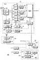
제2도는 본 발명의 실시예에 따른 가입자 유닛의 CDMA 수신기의 블럭도.2 is a block diagram of a CDMA receiver of a subscriber unit according to an embodiment of the present invention.
제3도는 본 발명의 실시예에 따른 CDMA 가입자 유닛의 로케이션 파인딩을 도시한 도면.3 illustrates location finding of a CDMA subscriber unit in accordance with an embodiment of the present invention.
제4도는 본 발명의 실시예에 따른 CDMA 가입자 유닛의 로케이션을 위해 전파 지연을 결정하는데 사용되는 타이밍 시퀀스를 도시한 도면.4 illustrates a timing sequence used to determine propagation delay for the location of a CDMA subscriber unit in accordance with an embodiment of the present invention.
제5도는 본 발명의 실시예에 따른 기지국의 CDMA 수신기의 블럭도.5 is a block diagram of a CDMA receiver of a base station according to an embodiment of the present invention.
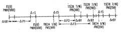
제6도는 본 발명의 실시예에 따라 가입자를 계산하는데 사용되는 전파 및 지연 시간들을 도시한 타임라인.6 is a timeline showing propagation and delay times used to calculate a subscriber in accordance with an embodiment of the present invention.
제7도는 본 발명의 실시예에 따라 가입자가 기지국 신호들을 측정하는 프로세스를 도시한 플로우챠트.7 is a flowchart illustrating a process by which a subscriber measures base station signals in accordance with an embodiment of the present invention.
제8도는 본 발명의 실시예에 따라 기지국이 가입자 신호들을 측정하는 프로세스를 도시한 플로우챠트.8 is a flowchart illustrating a process by which a base station measures subscriber signals in accordance with an embodiment of the present invention.
여타 문제점들은 본 발명에 따른 향상된 방법 및 장치에 의해 해결된다. 본 발명의 양호한 실시예는 코드 분할 다중 액세스(CDMA) 셀룰러 시스템에서 사용자의 로케이션을 결정하기 위한 시스템이다. CDMA 변조 정보를 사용하여, 가입자유닛에서의 제1 도달 광선의 비행 또는 전파 시간이 추정된다. 제1수신 광선은 기지국과 가입자 간의 최단 경로를 통상 나타내고, 비행 추정 시간은 가입자와 기지국 간의 거리 계산을 가능하게 한다. 다수의 예를 들면 3개의 사이트들과의 거리를 계산함으로써, 특정 가입자 로케이션이 측정 타이밍과 다른 프로세싱 지연들의 정확성으로 계산되고 제한될 수 있다.Other problems are solved by the improved method and apparatus according to the present invention. A preferred embodiment of the present invention is a system for determining a user's location in a code division multiple access (CDMA) cellular system. Using the CDMA modulation information, the flight or propagation time of the first arriving ray at the subscriber unit is estimated. The first received ray typically represents the shortest path between the base station and the subscriber, and the flight estimation time enables the distance calculation between the subscriber and the base station. By calculating the distance to many sites, for example three, a particular subscriber location can be calculated and limited to the accuracy of measurement timing and other processing delays.
양호한 실시예에서 각각의 기지국과 가입자 간의 신호 비행 시간은 상관 관계 수신기 내에서 자동적으로 계산된다. 프로세싱 단계들은 칩 정확성 하에서 시간 정렬된(예를 들면, 칩의 1/16번째) PN(Pseudo Noise) 시퀀스 코드화된 신호의 송신, 및 상관 관계 알고리즘을 사용하는 수신기의 신호에 대한 상관 관계를 포함한다. 변조 시퀀스(얘를 들면, PN 시퀀스)가 인식되어 있고 동기화/디스프레딩에 사용되기 때문에, 소정의 칩의 정확한 수신 시간이 결정될 수 있다. 다수의 관련 신호들의 수신 시간을 결정함으로써, 시간 지연이 계산되어 위치 추정치를 결정하는데 사용될 수 있다.In the preferred embodiment the signal flight time between each base station and subscriber is automatically calculated within the correlation receiver. Processing steps include transmission of a time-aligned (eg, 1 / 16th of chip) Pseudo Noise (PN) sequence coded signal under chip accuracy, and correlation to a receiver's signal using a correlation algorithm. . Since the modulation sequence (eg, PN sequence) is recognized and used for synchronization / despreading, the exact reception time of a given chip can be determined. By determining the reception time of multiple related signals, a time delay can be calculated and used to determine the position estimate.
하나의 구현에서, 가입자는 동시에 송신된 서로 다른 베이스들(표준 및/또는 보조 베이스들)로부터 관련된 PN 칩들을 결정하고, 또한 이 관련된 칩들의 수신 시간을 결정하기 위해 인식된 PN 시퀀스와 오프셋 정보를 사용한다. 수신 시간들의 차이로부터, 시간 차동이 결정됨으로써 거리 차동이 결정된다. 베이스들의 거리 차동과 인식된 위치를 사용하여, 위치 추정치가 결정된다. 가입자가 하나 또는 2개의 베이스들과 통신하는 경우에만, 베이스들이 활성 집합(필요하면, 보조 사이트들을 포함)에 추가되어 시간 측정이 가입자에 의해 이루어질 수 있다.In one implementation, the subscriber determines relevant PN chips from different bases (standard and / or secondary bases) transmitted simultaneously, and also recognizes the recognized PN sequence and offset information to determine the reception time of these related chips. use. From the difference in reception times, the distance differential is determined by determining the time differential. Using the distance differential of the bases and the recognized position, a position estimate is determined. Only when the subscriber communicates with one or two bases, the bases are added to the active set (including secondary sites, if necessary) so that time measurement can be made by the subscriber.
다른 구현에서, 선택된 칩들의 시간 측정을 위해 베이스 사이트 수신이 제어되고, 수신 시간의 차이가 유사하게 가입자 위치를 계산하는데 사용된다. 추가 수신 사이트들이 간섭 등으로 인해 필요한 경우, 보조 사이트들이 가입자 유닛으로부터 송신된 신호들을 수신하도록 제어된다. 필요하면, 비상시에, 가입자유닛은 최대 파워 레벨로 파워 업 되어 적어도 3개의 기지국들이 신호를 수신하여 시간을 추정할 수 있다. 또한, 보다 정확한 측정들이 필요한 경우, 특정 로케이션 메시지가 가입자에게 송신될 수 있다. 수신 시에, 가입자는 응답 신호를 위함 칩/시간 오프 셋을 결정하고, 오프셋을 인코드하여 응답 신호를 송신한다. 오프셋을 디코딩하고 오프셋을 결정하는데 사용된 동일한 칩(예를 들면, 프레임의 제1칩)의 수신 시간들을 비교할 때, 지연 보상 시간 값이 다수의 전파 경로들을 위해 결정되고, 이들로부터 위치가 결정된다. 결국, 더 멀리 있는 베이스에서 수신된 신호를 획득하는 것이 어려울 수 있기 때문에, 비상 로드 쉐딩(emergency load shedding)이 여분의 범위를 제공하기 위해 주변 베이스들에서 실행될 수 있는데, 이는 용량이 CDMA 무선 시스템의 범위에 따라 교체될 수 있기 때문이다. 따라서, 유효 범위가 향상되고, 로케이션 파인딩이 보다 신뢰성 있게 이루어진다.In another implementation, base site reception is controlled for timing the selected chips, and the difference in reception time is similarly used to calculate subscriber location. If additional receiving sites are needed due to interference or the like, the secondary sites are controlled to receive signals transmitted from the subscriber unit. If necessary, in an emergency, the subscriber unit can be powered up to the maximum power level so that at least three base stations can receive the signal and estimate the time. Also, if more accurate measurements are needed, a specific location message can be sent to the subscriber. Upon reception, the subscriber determines the chip / time offset for the response signal, encodes the offset and transmits the response signal. When comparing the reception times of the same chip (eg, the first chip of the frame) used to decode the offset and determine the offset, a delay compensation time value is determined for multiple propagation paths and the location is determined from them. . As a result, since it may be difficult to obtain a signal received at a farther base, emergency load shedding can be performed at the surrounding bases to provide extra range, which means that the capacity of the CDMA wireless system is reduced. It can be replaced according to the range. Thus, the effective range is improved and location finding is made more reliable.
제1도를 참조하면, 일반적으로 기지국들(110,120, 130) 및 가입자(140)를 구비한 6방 정계의 셀 패턴을 갖는 셀룰러시스템(100)이 도시되어 있다. 보조 베이스 유닛들(121)은 또한 베이스들(110, 120 및 130) 사이에 배치된다. 베이스들(110, 121 및 130)과 가입자 유닛(140) 간의 거리는 수신기가 송신 신호에 대한 상관 관계를 실행하는 시점에서 선정된 기준 시간으로부터 측정된 제1 도달 광선의 비행 또는 전파 시간을 결정함으로써 추정된다. 이것은 수신기의 임의의 시간 기준 점에 대한 측정이 이루어지기 때문에[GPS 신호 또는 자동 클록으로부터 유도된 시스템과 같이 보다 정확한(그리고 비용이 많이 드는) 타임 시스템이 가입자(140)에서 사용될 때만 정확한 측정이 유용할 수 있음] 거리 추정치가 과대 평가되거나, 과소 평가될 수 있다는 점에서 보다 어렵게 된다. 따라서, 거리들(150, 160 및 170) 각각은 칩 레이트[약 814ns 칩 레이트, 즉, PN 시퀀스 레이트에 의해 TIA(Telecommunications Industry Association) Intermin Standard IS-95A에서 결정된 최대 확산 신호 레이트], 또는 약 250m/칩에 대한 상관 관계를 기초로 베이스들(110, 121 및 130) 각각과 가입자 유닛(140) 간의실제 거리 보다 길거나 또는 짧을 수도 있다. 따라서, 칩 레이트 보다 빠른 시간 측정을 달성하는 것이 바람직하다. 제1도에서, 거리(150)는 가대 평가된 것으로 도시되는데 가입자 유닛의 실제 로케이션을 넘는 점(125)을 나타낸다. 유사하게 점들(115 및 135)도 또한 과대 평가된다. 이 점들은 이하에 기술된 거리 프로세싱에 의해 보정될 것이고, 가입자의 실제 로케이션에 훨씬 근접한 추정치를 산출한다.Referring to FIG. 1, a
제2도는 CDMA 수신기 (201), 로케이터 유닛(202), 및 송신기(203)을 갖는 CDMA 가입자 유닛(200)을 도시한 블럭도이다. 수신기(201)는 3개의 독립 레이크 입력들(210, 220, 230)을 공급하는 공통 RF(무선 주파수) 정면 단부(205)를 갖는다. 이 레이크 유닛들(210, 220 및 230)은 약 1 PN 칩 시간 또는 더 멀리 떨어진 3개의 서로 다른 수신 광선들로 로크할 수 있는데, 이는 통상 다이렉트 시퀀스 확산 스펙트럼(DSSS) 수신기이다. 탐색기(240)는 칩 레이트 보다 빠르게 (양호한 경우에는 50ns 클록 레이트만큼 신속한 해상도가 가능) 새로운 보정 피크들을 스캔하고, 현 채널 상태의 최상 추정치를 기초로 레이크 입력들을 재할당할 수 있다. 통상, 레이크들(210, 220 및 230)용 상관기들은 유용한 3개의 최강 광선들로 로크하고, 제2 또는 제3 기지국이 충분히 강한 신호를 공급할 수 있을 때, IS-95A 규격에 의해 기술된 바와 같이, 각각, 1 PN 칩 시간 보다 많은 시간으로 지연된 다른 기지국 신호들로 로킹하기 위해 예약된다. 2개의 기지국들만이 충분히 강한 경우, 2개의 광선들은 각각의 기지국용으로 전용되고, 제3광선은 다른 기지국을 위한 최강 광선으로 남게 된다.2 is a block diagram illustrating a
가입자(200)에 의해 로케이션 파인딩 기능이 요구될 때, 로케이션을 정확하게 추정하기 위해 충분한 정보가 유용하도록 각각의 광선을 위한 서로 다른 3개의 기지국들을 파인드하고자 시도하는 것이 양호하다. 따라서, 3개의 베이스 사이트들을 연결하기 위해 레이크들(210, 220 및 230)은 적어도 3개의 베이스 유닛 신호들이 디코드되도록 조정된다. 유용하면, 베이스 사이트들 사이에 물리적으로 배치된 비상 감지 발생기들[제1도의 보조 베이스 유닛(121)과 같은]이 추가 기준 신호들에 따라 영역을 블랭킷하기 위해 비콘 요청에 응답해서 활성화 될 수 있다. 그렇게 함으로써, 가입자가 표준 베이스 사이트들 뿐만 아니라 감시 발생기들을 기초로 로케이션 추정을 하게 된다. 이 보조 유닛들은 주위 기지국들 외에 서로 다른 PN 오프셋을 갖고, 통상 적합한 동기화/타이밍을 위해 GPS 수신기에 장치된다. 이들은 임의의 편리한 수단, 즉, 와이어리스 또는 트위스티드 페어 케이블에 의해 하부 구조로 기지국들 또는 다른 제어기에 결합된다. 이 동작은 3개 미만의 베이스들이 유용하다는 가입자에 의한 지시에 따라, 제어기에 대한 요청, 또는 그 제어하에서 서빙 기지국으로부터 로컬 보조 유닛으로의 커맨드에 의해 양호하게 달성된다. 대안으로, 보조 유닛들은 가입자에 의한 요청 신호에 응답해서, 제한된 기간(즉, 시스템 간섭을 최소화하기 위해, 5초) 동안 송신을 개시하는 스캐닝 수신기들과 장치될 수 있다. 적합한 대체에 의해, 보조 유닛들은 특정 로케이션들의 불확실성을 감소시키거나, 주 고속도로, 중앙 분리대 또는 중심 상업 지구와 같은 전략 영역에서의 위치 파인딩의 정확성을 증가시키는데 사용될 수 있다. CDMA 시스템의 간섭-제한 속성 때문에, 몇몇 경우에, 하나의 기지국만이 가입자의 신호를 수신할 수 있고, 그 역도 가능하여서, 필요한 다수의 판독력을 획득하기 위해 보조 유닛들이 필요하다.When a location finding function is required by the
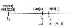
각각의 신호의 수신 관련 시간은 탐색기의 관련 보정 피크들의 전연(또는 대안으로, 피크들)에 대한 정보를 사용하고, 미세 시간 정렬 회로[즉, 필터들(250-270)과 결합된 각각의 브랜치용 지연 로크 루프(DLL)(215, 225 또는 235)]에서 결정된 오프셋에 의해 이를 조정함으로써 결정된다. 양호하게 관련 보정 피크들이 서로 하나의 칩 내에서 서로 다른 브랜치들을 통해 수신된다. 이 방법에서, 전연의 정확한 시간이 PN 시퀀스 번호[즉, 반복 PN 시퀀스(예를 들면, 길이가 약 16,000 칩들)의 칩 위치(즉, 번호(245))]와 함께 결정된다. 이미 결정된 PN 시퀀스 오프셋, 및 베이스 PN 시퀀스가 각각의 기지국을 위한 시퀀스와 동일하고, 동일한 시스템 시간 플러스 또는 마이너스 특정 PN 시퀀스 오프셋으로 송신되는 시스템 디자인을 사용하여, 관련 시간의 차이가 전파 경로 지연의 차이를 야기한다. 이것은 제3도에 도시되어 있다. 시간 T0일 때 2개의 베이스들(B1 및 B2)는 송신 중이지만, 베이스(B1)는 PN 칩 0을 송신하고, 베이스(B2)는 PN 칩(256)을 송신하는데, 이는 256개의 칩들의 PN 시퀀스 오프셋을 갖기 때문이다. 소정의 시간 T1일 때, 로케이션 파인딩이 활성화된 후에, 가입자는 B1으로부터 PN 칩 4의 전연이 수신되었다고 결정한다. 베이스(B2)로부터의 PN 칩의 다음 전연은 시간 T2일 때 칩의 1/8번째 후에 수신되고, 칩은 PN 시퀀스의 280번째로 결정된다. 수신 시간들 및 PN 번호들로부터, 전파 지연 차이가((PNB2-오프셋) + (수신 차이, T2-T1)) - (PNB1-오프셋) = ((261-256) + (1/8)) - (4-0) = 1 1/8칩들 * 814ns/칩 = 916ns로 계산된다. 무선 신호의 약 1/3 m/ns 전파 속도로, 이 차이는 전파 경로 거리들의 약 300m 차이로 해석된다. 로케이션의 정밀도는 사용된 시스템 클록 레이트와 동기화 정도에 의해서만 제한된다. 모든 기지국들이 GPS 타이밍 정보를 사용하는 경우, 50ns(또는 칩 레이트의 약 1/16) 내에서 동기화된 송신(즉, 칩의 전연)이 가능하다. 적어도 동일한 20MHz 클록 레이트를 발생시키는 로컬 클록의 경우에, 100ns 또는 30m 내에서 로케이션이 가능하다.The reception related time of each signal uses information about the leading edge (or alternatively, the peaks) of the relevant correction peaks of the searcher, and each branch combined with a fine time alignment circuit (ie, filters 250-270). For the delay lock loop (DLL) 215, 225 or 235). Preferably the relevant correction peaks are received over different branches in one chip from each other. In this method, the exact time of the leading edge is determined along with the PN sequence number (ie, the chip position (ie, number 245) of the repeating PN sequence (eg, about 16,000 chips in length)). Using a system design in which the PN sequence offset already determined, and the base PN sequence are the same as the sequence for each base station, and are transmitted at the same system time plus or minus a specific PN sequence offset, the difference in relative times is the difference in propagation path delay. Cause. This is shown in FIG. At time T0 two bases B1 and B2 are transmitting, but base B1 transmits
제2도를 참조하면, DLL(215, 225 및 235)은 미세 시간 정렬 신호들을 출력하기 위해 신호들을 조정하기 위해 각각의 레이크들(210, 220 및 230)에 각각 공급된다. 상술된 바와 같이, DLL 출력들은 각각의 DLL(215, 225 및 235)의 출력들을 효과적으로 평균화하는 각각의 채널에 대해 저통과 필터(LPF : 250, 260, 270)로 필터링한 후에 양호하게 PN 칩들의 수신 시간들을 조정하기 위해 미세 위상 오프셋 정보로서도 또한 작용할 수 있다. 탐색기(240)(PN 칩/시간 검출에 적용됨)로부터의 칩 번호/시간/베이스 식별 또는 오프셋(즉, B1-B3 정보)과 함께 평균화된 미세위상 오프셋 정보가 로케이션 탐색기(280)에 공급된다. 로케이션 탐색기(280)는 각각의 브랜치로부터 미세 위상 오프셋 정보를 취하고 각각의 칩에 대한 탐색기(240)로부터의 수신 시간을 보정하여 각각의 브랜치에 보정된 관련 수신 시간을 제공한다. 초기 시간, 말하자면 B1(즉, 베이스(1)로부터 신호가 수신된 시간)으로부터, 다른 신호들(B2 및 B3)의 수신 시간의 차이(tB21 및 tB31)가 결정되고, 대응 거리들(dB21 및 dB31)이 결정된다. 따라서 베이스들[1(110), 2(120) 및 3(130)]로부터의 거리는 각각 dB1, (dB1+dB21) 및 (dB1+dB31)임을 안다. 또한, PN 오프셋으로부터, 베이스들의 식별이 인식되고 지리학적 위치가 메모리(281)로부터 검색될 수 있다. 그 후 모빌의 지리학적 좌표들을 결정하기 위해 제4도에 도시된 바와 같이 탐색 루틴을 간단히 실행한다. 제4도의 일례에서, 인식된 베이스 로케이션들은 3개의 라인들[L12(151), L23(152) 및 L13(153)]을 정의하는데 사용된다. 거리들(dB21 및 dB31)은 라인들[L12(151), L23(152) 및 L23(152)]로부터 각각 감산되고, 나머지 세그먼트들은 정규 라인들[N12(154), N23(156) 및 N13(155)]에 의해 이분된다. 3개의 라인들[N12(154), N23(156) 및 N13(155)]의 교차점을 가입자(140)의 위치이다. 이 정보는 그 후 서빙 로케이션 레지스터의 요청국에 발송되기 위해 서빙 기지국에 송신되거나, 가입자의 사용을 위해 (예를 들면, 도시되지 않은 맵 그리드 또는 다른 로케이션 디바이스를 통해) 발송될 수 있다.Referring to FIG. 2,
대안으로, 베이스 사이트 로케이션 정보가 가입자에게 유용하지 않으면, 위상 오프셋, 칩, 타이밍과 베이스 오프셋 정보는 로케이션 요청 신호로 서빙 기지국에 송신될 수 있다. 거기서 로케이션 탐색기는 자신의 데이타베이스를 액세스하여 가입자 로케이션을 결정할 수 있다. 이 로케이션 정보는 그 후 로케이션 응답 메시지로 가입자 또는 다른 요청 엔티티에 다시 송신된다.Alternatively, if base site location information is not available to the subscriber, phase offset, chip, timing and base offset information may be sent to the serving base station as a location request signal. There, the location explorer can access its database to determine the subscriber's location. This location information is then sent back to the subscriber or other requesting entity in a location response message.
제1 CDMA 기지국(301)을 갖는 CDMA 하부 구조 시스템(300)의 블럭도를 일반적으로 도시하고 있는 제5도를 참조하여 하부 구조 장치를 사용하는 양호한 로케이션 방법을 알 수 있다. 베이스(301)는 4개의 독립 레이크 입력들(310, 320, … 330)을 공급하는 공통 RF 정면 단부(305)를 갖는다. 이 레이크들은 통상 DSSS 수신기인 적어도 1 PN 칩 시간 떨어져 있는 4개의 서로 다른 수신 광선들로 로크할 수 있다. 2개의 탐색기들(340)은 새로운 보정 피크들을 스캔하고, 현 채널 상태들의 최상 추정치를 기초로 레이크들을 재할당 할 수 있다. 통상, 레이크들(310, 320 및 330)의 4개의 상관기들은 유용한 4개의 최강 광선들로 로크한다.Referring to FIG. 5, which generally shows a block diagram of a
로케이션 파인딩 기능이 요구될 때, 2개의 일반적인 방법들, 즉, 수동적인 방법(가입자 유닛 응답이 없음)과 능동적인 방법이 유용하다. 다른 경우에는 로케이션을 추정하기 위해 충분한 정보가 유용하도록 가입자 신호를 수신할 수 있는 적어도 3개의 서로 다른 기지국들을 파인드하는 것이 양호하다. 제1실시예 수동형 모드에서, 베이스(301)의 4개의 레이크 브랜치들(310,320...330)이 업링크 신호를 검출하는데 사용된다. 각각의 레이크로부터 지연 로크 루프(DLL)가 상호 관련된 광선의 타이밍을 추정(즉, 조정)하는데 사용된다. DLL은 상술된 가입자 유닛에 의해 사용된 프로세스와 유사하게 상관 관계 시간을 보다 정확하게 추정한다. 탐색기 및 칩/시간 검출기(340) 피크는 각각의 브랜치 상의 신호를 상관 관계하고, 또한 사용될 최상 브랜치를 결정하고(양호하게 동일한 칩의 초기 수신 피크를 기초로, 그러나 다른 선택 기술이 현 최상 브랜치를 경정하는데 사용될 수 있음); 이 최상 브랜치 신호는 PN 칩을 결정하는데 사용되고 가입자 탐색기(240)와 유사하게 시간 정보를 수신한다.When location-finding functionality is required, two general methods are available: passive (no subscriber unit response) and active. In other cases, it may be desirable to pin at least three different base stations that can receive a subscriber signal so that enough information is available to estimate the location. First Embodiment In passive mode, four
로케이션 프로세스를 초기화하기 위해, 양호한 실시예에서 모빌 스위칭 센터(MSC: 365), 동작 센터와 같은 영역 엔티티에서 처럼 시스템(300) 내에서, 또는 PSTN(public switched telephone network: 375)과 같은 연결 네트워크 내에서 초기화된다. 로케이션 요청은 그 후 현 서빙 기지국(들)을 결정하기 위해 홈 로케이션 레지스터(HLR: 366)를 통해 프로세스된다. 로케이션 커맨드 수신 시에, 베이스(301)의 프로세서(350)(및 다른 서빙 베이스들의 유사한 프로레서들)은 칩 수신 시간을 결정하기 위해 검출기(340)를 사용한다. 양영호하게 이것은 예를 들어 선정된 칩 번호(예를 들면, 10)에 대한 각각의 64번째 칩(즉, PN 시퀀스 번호 0, 64, 128 등)의 상승 시간을 결정함으로써, 특정 그룹의 PN 칩들의 전연 상승 시간을 결정하는 모든 베이스들에 의해 달성된다. 이 정보는 그 후 ID와 함께 각각의 베이스 수신기에 의해 지정된 엔티티, 예를 들면, BSC(base site controller: 360)의 로케이션 탐색기(361), 또는 HLR(366)의 로케이션 탐색기(367) 등에 발송된다. 따라서, 동일한 칩들의 수신 시간의 차이는 전파 지연 차이들을 결정하는데 사용될 수 있다. 각각의 칩은 동일한 단일 칩 송신으로부터 유도된다. 다시 말하면, 각각의 칩 번호에 있어서 서로 다른 베이스들의 수신기 시간 간의 차동은 전파 차이를 야기하고, 로케이션은 제4도에 도시된 방법과 유사한 방법으로 수신 베이스들의 인식된 로케이션과 관련하여 정보를 결정할 수 있다. 비교적 짧은 시간 프레임(예를 들면, 10시간, 모든 64개의 칩들, 약 500μs)으로 다수의 정보 집합을 취하고, 평균화하거나 결정된 위치들을 사용하여 가장 적합하게 계산함으로써, 위치 에러들이 최소화될 수 있다. 숙련된 자들은 다른 방법이 실제 계산에 사용될 수 있음을 안다. 예를 들면, 지정된 시스템 시간 및 칩 번호로부터의 시간 차이들과 함께 지정된 시간의 하나의 칩 내에서 전연에 대한 동일 시스템 시간의 검출이 전파 지연 차이들을 결정하는데 사용될 수 있다.[서로 다른 칩들의 송신 시간이 가입자의 클록 레이트의 정확성에 의해 제한되기 때문에, 추가 에러가 발생할 수 있음에도 불구하고; 50ns클록 사이클이 제공되었더라고, 이것은 동일한 칩(타이밍 에러를 갖지 않음)의 송신으로부터 제공되는 것 보다 여전히 더 많은 에러를 갖는다.] 중요한 점은 칩 ID(즉, PN 시퀀스의 번호/위치) 및 서로 다른 베이스들의 정확한 수신 시간(예를 들면, 오버샘플된 크록 레이트의 전연, 또는 피크)가 가입자 로케이션을 결정하는데 사용된다는 점이다.In order to initiate the location process, in the preferred embodiment within the
액티브 로케이션에 대한 양호한 실시예에서, 투웨이 레인징 시스템은 가입자로부터의 칩 수신 시간 정보와 특정 응답 정보를 모두 사용하여 구현된다. 이 실시예에서, 프로세스는 가입자와 통신하는 베이스(301)에 발송된 시스템 하부 구조의 로케이션 요청에 따라 다시 초기화된다. 프로세서(350)는 인코더(352)와 확산 변조기(355)에 의한 적합한 인코딩을 위해 로케이션 요청 신호(LOC_S 351)를 발송한다. 시스템 클록(353)(양호하게 유도 GPS, 자동 클록과 같은 다른 정확한 수단이 사용될 수 있음)을 사용하여, 미세 시간 조정기(354)(예를 들면, 스트로브 발생기)는 양호하게 50ns 정확성 내에서 출력 칩들이 전연을 정확하게 출력하기 위해 변조기(355)를 제어한다. 프로세서(350)는 또한 변조기(355)와 클록(353)를 통해 기준 칩(즉, 시스템 시간 TS(0)일 때의 16384 칩 시퀀스의 칩(1024)에 대한 정확한 시스템 시간을 결정한다. 그 후 이로부터 다른 칩 송신 시간들이 결정될 수 있다. 출력 칩 시퀀스는 그 후 가입자에게 전송된다.In a preferred embodiment for active location, the two-way ranging system is implemented using both chip reception time information from the subscriber and specific response information. In this embodiment, the process is reinitialized according to the location request of the system infrastructure sent to the base 301 in communication with the subscriber.
제2도를 다시 참조하면, 로케이션 요청 신호(351)의 복조 및 수신에 이어, 프로세서(280)는 상술된 방법과 유사한 방법으로 다음 PN 칩의 ID와 타이밍 정보를 결정하기 위해 탐색기(240)를 제어한다. 편의상, 결정된 칩이 가입자 관련 시간 TR(0)일 때 1088(베이스 PN 시퀀스 중)이라고 하자. 가입자 내에서 회전 시간에 대한 정확한 정보를 제공하기 위해, 프로세서(280)는 그 후 가입자 PN 시퀀스의 선정된 칩이 다음으로 송신될 로컬 시간을 결정한다. 편의상, 이 선정된 칩은 송신될 반복 시리즈들(즉 가입자 PN 시퀀스의 50번째 칩들 모두) 중 하나[즉, 칩(100)]로 양호하게 선택된다. 임의의 다른 칩, 즉, 다음 20ms 프레임의 제1칩이 선택될 수 있는데, 양호하게 가입자 정밀도-타이밍 출력 요구 사항들과 시스템 로케이션 프로세싱을 최소화하기 위한 것이다. 임의의 경우에, 송신기 회로(203)의 변조기(291)로부터의 출력의 선택된 칩 로컬 시간은 예를 들면 선정된 칩 출력 시간[즉, TR(24 1/16)의 칩(100), 관련 시간은 칩 레이트 간격들로 측정됨]을 결정하기 위해 현 칩 출력 시간[예를 들면, PN/시간 검출기(292)를 통해]을 결정하고 계산함으로써 결정된다. 물론, 진행중인 현 송신이 없다면, 선정된 칩의 송신 전에 베이스들이 가입자 PN 시퀀스에 트레인하기 위해 충분한 지연 시간(예를 들면, 약 2초)이 제공된다. 프로세서는 그 후 인코더(290)에 의한 인코딩을 위해 로케이션 응답 신호(RESP 282)를 발송하고, 결정된 시간[즉, TR(24 1/16)]에 선정된 칩을 정확하게 출력하기 위해, 또한 정기적인 그룹의 칩들이 모니터되면, 선정된 기간 동안 정기적인 그룹의 임의의 다음 칩들(예를 들면, 칩(15,200) 등)을 정확하게 출력하기 위해 변조기(291)를 제어한다. RESP(282)는 베이스 칩 정보(1088, TR(0)), 선정된 칩 정보(100, TR(24 1/16))와, 가입자 유닛 프로필의 부분으로서 하부 구조에 의해 미리 인식되지 않은 경우, 획득 및 포스트-출력 지연들을 위한 선정된(즉, 교정/계산된)가입자 지연 팩터[즉, 안테나의 신호가 탐색기(240)에 도달하고, 변조기(291)로부터의 시간-정밀도 출력에 이어 출력 신호가 안테나에 방사되는데 걸린 시간]를 포함한다.Referring back to FIG. 2, following demodulation and reception of the location request signal 351, the
제5도를 참조하면, 동일한 시간에 시스템은 로케이션 요청 신호)351)를 송신하도록 베이스(301)를 제어하고, 또한 로케이션 정보 기억을 개시하도록 다른 통신 베이스들에게 통지한다. 통신중이거나(즉, 소프트-핸드오프) 가입자 신호를 수신할 수 있는 3개 미만의 베이스들이 있는 경우, 발신 엔티티(예를 들면, 로케이션 탐색기들/프로세서들(361 또는 367))는 가입자 지정 주파수로 수신을 개시하도록 서빙 베이스들의 주변에 배치된 베이스(356)와 같은 하나 이상의 보조 기지국들에 명령한다. 따라서, 가장 간단한 구현에서, 보조 베이스들은 정확한 시스템 클록(에를 들면, GPS-접속 클록)에 따라 회전 가능한 수신기들일 수 있고; 보조 베이스가 와이어라인을 통해 BSC에 접속되지 않았으며, 보조 베이스는 고정 가입자 유닛(와이어리스 액세스 고정 유닛(WAFU)와 같은)으로서 구현될 수 있고, 가입자로부터의 차이는 WAFU가(예를 들면, GPS 클록을 통해) 시스템 시간에 동작한다는 점이다. 이 후자의 실시예에서 WAFU는 자신의 서빙 기지국, 예를 들면, 베이스(301)를 통해 로케이션 응답 정보를 전달한다.Referring to FIG. 5, at the same time, the system controls the base 301 to transmit location request signal 351, and also notifies other communication bases to initiate location information storage. If there are less than three bases in communication (ie, soft-handoff) or capable of receiving a subscriber signal, the originating entity (eg, location seekers /
모든 수신 베이스들, 예를 들면, 베이스(301)와 보조 베이스(356)는 로케이션 요청을 초기화할 때 가입자 칩/시간 정보를 기억하기 시작한다. 기억 정보는 선정된 기간 동안 수신된 각각의 칩의 시간(예를 들면, 전연 수신 시간)과 칩 번호일 수 있다. 하나의 20ms 프레임에 25,000 엔트리에 근접함을 의미하는 모든 칩을 저장하는 것 외에, 정기적인 번호의 칩들(예를 들면, 시퀀스의 50번째 칩 모두)가 모든 수신 베이스들에 의해 양호하게 사용되고, 후자의 경우에 가입자는 정기적인 칩들중 하나(칩(100)과 같은)인 선정된 칩을 선택하도록 상술된 바와 같이 구성된다. 숙련된 자들은 정보가 에러를 최소화하기 위해 모든 베이스들의 동일한 칩 상에 수집되지 않는 한 임의의 수의 기간들, 또는 특정 칩들(예를 들면, 프레임의 제1칩)이 사용될 수 있음을 안다. 양호하게, 편의상, 적합하게 구성된 가입자는 베이스들에 의해 모니터되는 칩들과 일치하도록 선정된 칩을 선택할 것이고, 따라서 후에 계산을 간단하게 하며; 선택은 프리프로그래밍을 기초로 또는 모니터될 칩(들)/기간을 나타내는 로케이션 요청 신호(351)의 데이타에 따라 이루어질 수 있다(이 경우에 선정된 칩들만이 정확하게 출력될 필요가 있다).All receiving bases, for
가입자로부터(양호하게 임의의 전진 음성/데이타 통신으로 대역내 주파 신호 방식을 통해 송신된) 확산 RESP 신호를 수신할 때, 베이스(301 및 356)의 프로세서들(350 및 358)은 신호와 선정된 칩 정보를 검출하고, 몇몇 선정된 번호의 칩/시간 쌍들을 로케이션 탐색기(361 또는 367)에 발송한다. 예를 들어, 향상된 정확성을 평균화하기 위해, 각각의 베이스(301,356)는 RESP 신호 정보(예를 들면, 베이스 칩/시간 쌍{(베이스)1088, TR(0)}, 선정된 칩/시간 쌍{(가입자)100, TR(24 1/16)}, 및 인식된 지연 팩터{4/32})와 함께 선정된 칩 및 수신 시간으로 시각하여 8개의 칩/시간 쌍들[예를 들면, 쌍들 {100, TS(28 7/16)}, {150, TS(78 7/16)}, ... {450, TS(378 8/16}]를 발송할 수 있다. 이 시퀀스를 도시하는 타임라인은 제6도에 도시되어 있다. TS(0)는 편의상 시스템 클록의 0번째 비트로서 도시된 개시 시스템 타임을 나타내고, TR(0)은 가입자 관련 클록 시간을 나타낸다. PNB1(1088)은 제1기지국(301) PN 시스템의 1088번째 칩을 나타내고, PNS(100)은 가입자 PN 시스템의 100번째 칩을 나타낸다. 따라서, 베이스 칩(1088)은 시스템 시간 0일 때 출력되고, 전송 지연 시간 ΔtB1 후에 베이스 안테나로부터 방사된다. 전파 지연 ΔP1과 가입자 수신 지연 시간 ΔrS(즉, 가입자 안테나로부터 검출기(240)로의) 후에, 검출기(240)는 TR(0)일 때 수신될 칩(1088)을 결정한다. 그 후 프로세서(280)는 칩(100)이 될 가입자 시스템의 다음 50번째 칩을 결정하고, 현 가입자 칩/시간으로부터 계산하여, 칩(100)의 출력 시간이 TR(24 1/16)이 된다. 교정 지연들 ΔrS와 ΔtS(안테나 방사에 대한 출력으로부터의 지연), 즉, 2/32 칩들 각각을 인식하여, 가입자는 정보, 예를 들면, [{1088, TR(0)}, {100, TR(24 1/16)}, {4/32}]를 포함하는 REST 신호(282)를 송신한다.When receiving a spread RESP signal from the subscriber (preferably transmitted via an in-band frequency signaling scheme with any forward voice / data communication), the
베이스(301) 검출기(240)는 각가 전파 및 수신(즉, 안테나로부터 검출기로의 )지연들 ΔP2, ΔB1 및 ΔP3, ΔrB2에 따라 시스템 시간 TS(28 7/16)에 가입자 칩(100)을 수신하고 베이스(357)는 시간 TS(29 7/16)에 수신한다. 유사한 반복 측정이 실행된다. 예를 들어, 베이스(301)는 시간 TS(78 7/16)에 칩(150)을 수신하고, 가입자는 TR(74 1/16)로, 즉, 정확히 50개의 칩들(40, 700ns)후에 칩(150)의 출력 시간을 제어한다.
선정된 수의 쌍들이 결정된 후에, 칩/시간 정보와 응답 신호 정보는 로케이션 탐색기(361 또는 367)에 발송된다. 탐색기(361 또는 367)는 그 후 다른 인식 정보를 사용하여 전파 지연들, 예를 들면, ΔP1-ΔP3을 계산한다. 이 경우에, 교정 베이스 지연들 ΔtB1, ΔrB1 및 ΔrB2가 5/32, 3/32 및 3/32 칩들이라고 하자. ΔP1은 본래 ΔP2와 동일하기 때문에, 다음과 같다.After the predetermined number of pairs have been determined, the chip / time information and the response signal information are sent to the

따라서, ΔP1은 2칩들이거, 또는 1628ns이고, 전파 경로 길이는 약 488m(총 불확실성이 100ns일 때 +/-30m)이다. ΔP1이 알려지면, ΔP3은 유사하게 계산되어, 도시된 바와 같이 시간이 3칩이고 거리가 733m로 산출될 수 있다. 적어도 3개의 수신기들에 대한 전파 경로 길이를 계산하고, (예를 들면, 데이타베이스(362 또는 368)로부터) 수신 베이스에 대한 로케이션 정보를 검색함으로써, 가입자 위치가 각각의 전파 경로들이 모두 교차할 수 있는 특정 점(또는 최고 확률의 작은 영역)을 계산함으로써 결정될 수 있다. 프로세서는 각각의 시간/칩 세트에 대해 반복된다. 다수의 점들/영역들로부터 가장 적합한 점/영역을 결정하기에 적합한 임의의 프로세스가 사용될 수 있음에도 불구하고, 각각의 계산 점(또는 가능한 영역의 중심)이 그 후 예를 들면 가장 간단하게 평균화함으로써 가입자 로케이션을 결정하는데 사용된다.Thus, ΔP1 is two chips, or 1628 ns, and the propagation path length is about 488 m (+/- 30 m when the total uncertainty is 100 ns). If ΔP1 is known, ΔP3 may be similarly calculated so that the time is three chips and the distance is calculated to be 733 m as shown. By calculating the propagation path length for at least three receivers and retrieving location information for the receiving base (eg, from
최대 가능 점/영역의 로케이션이 양호하게 HLR(366)의 사용자 프로필 데이타베이스(369)에 기억된다. 또한, 수초 또는 수분 정도의 하나 이상의 다른 시간 기간 후에, 전체 프로세스가 반복될 수 있고, 다수의 최대 가능 영역들이 가입자의 이동 속도 및 방향을 결정하는데 사용되고; 정확한 충분한 가입자 클록이 사용되는 경우 수분의 연장된 기간(즉, 시스템 시간으로부터의 가입자 클록 오프셋이 이 기간 동안 인식됨) 동안 50ns이하로 드리프트되어, 베이스들의 반복 검출이 요청 신호를 반복할 필요 없이 실행될 수 있다. 최종적으로, 결정된 로케이션, 및 이동 속도/방향은 고유 요청 엔티티로, 예를 들면, 오퍼레이터(370)로 PSTN(375)을 통해 발송된다.The location of the maximum possible point / area is preferably stored in the
비활성 프로세스에 비해 액티브 로케이션 프로세스를 사용하는 장점은 필요한 경우 3차원 정보가 보다 정확하게 결정될 수 있다는 점이다. 이것은 전파 경로들의 경사각이 수평으로부터 0도 보다 상당히 클 수 있는 도시 또는 구릉성 영역에서 특히 유용하다. 베이스들의 3차원 좌표들, 및 제1근사 가입자 로케이션의 인식된 지형학이 수동형 프로세스의 정확성을 증가시키는데 사용될 수 있고, 숙력된 자들은 전파 시간들의 차이에 대립해서 측정된 전파 시간으로부터 보다 양호하게 근사치가 유도될 수 있음을 안다. 3차원의 결정된 전파 경로들이 정확하기 때문에, 가능 로케이션의 3차원 영역을 결정하기 위해 x축 및 y축 좌표들과 함께 베이스 사이트 로케이션의 z축(즉, 제3 차원) 좌표들의 추가적인 프로세싱이 문제이다. 인식된 빌딩 및 지형학 정보와 비교되면, +/- 스토리(약 100ns 불확실성) 내에서 또는 양호하게 단일 빌딩 내에서의 로케이션이 가능할 수 있다. 관련 수신 신호 강도들 및 빌딩으로의 유사한 경로 손실 특성들과 같은 추가 정보가 가능 로케이션 영역을 더 축소시키는데 사용될 수 있다.The advantage of using an active location process over an inactive process is that three-dimensional information can be determined more accurately if needed. This is particularly useful in urban or hilly areas where the inclination angle of the propagation paths can be significantly greater than zero degrees from horizontal. The three-dimensional coordinates of the bases, and the perceived topography of the first approximate subscriber location, can be used to increase the accuracy of the passive process, and trained ones are better approximated from the measured propagation time as opposed to the difference in propagation times. Know that it can be induced. Since the three-dimensional determined propagation paths are accurate, additional processing of the z-axis (ie, third-dimensional) coordinates of the base site location along with the x- and y-axis coordinates is a problem to determine the three-dimensional region of the possible location. . Compared with the recognized building and topographical information, a location may be possible within +/- story (about 100 ns uncertainty) or preferably within a single building. Additional information, such as related received signal strengths and similar path loss characteristics to the building, can be used to further reduce the possible location area.
일반적으로 400으로 표시된 제7도는 로케이션 추정을 위해 기지국 신호들을 측정하는 가입자를 위한 시스템 프로세스의 플로우챠트를 도시한 것이다. 가입자에 의해(예를 들면, 가입자 초기화에 의해, 또는 차량 충돌을 나타내는 모션 센서와 같은 다른 지시기를 기초로 자동적으로) 실행될 로케이션 커맨드 발생을 나타내는 블록(405)으로 프로세스가 개시된다. 블록(410)은 가입자의 상태를 검사하고 가입자가 3-웨이 소프트 핸드오프인지의 여부에 따라 결정이 이루어진다(415). 그렇지 않으면, 후보 집합에 3개의 베이스들이 있는지를 검사하는 블록(420)이 실행된다. 그렇지 않으면, 후부 집합으로의 추가 베이스의 임계치를 검사하기 위해 결정 블록(425)이 검사된다. 최소가 아니면, 블록(430)은 임계치를 감소시키고 프로세스 단계(420)로 복귀한다. 블록(425)이 이미 최소 레벨이면, 블록(450)이 실행된다. 이 블록은 비상 기능과 비상이 아닌 기능간의 로케이션 기능을 차별한다. 따라서, 비상이 아닌 기능이 프로세스되면, 시스템 레벨 변경은 사용 레벨이 높지 않을 때만 가능한데, 이는 간섭 레벨을 증가시킴으로써 사용자 손실 서비스를 야기하기 때문이다. 하이 시스템 로딩시 비상이 아닐 때, 블록(460)이 실행된다. 비상이면, 블록(455)가 블록(460) 전에 실행된다. 이것은 보조 감시 발생기들이 회전되는 비상 비콘 신호에 응답해서 양호하게 발생하고, 자동적으로 응답하고; 대안으로, 비상 신호가 서빙 베이스에 송신되어서 보조 베이스가 활성화되도록 제어하기 위해 프로세스될 수 있다. 후자의 경우에, 제2 비상이 아닌 요청 신호가 유사하게 사용될 수 있고, 활성 커맨드는 제어 프로세서(예를 들면, 제5도의 BSC(360)의 프로세서/탐색기(361))가 시스템 로딩이 로딩 임계치 이하임을 나타내는 경우 발생한다. 따라서 블록(455)은 다수의 사이트들에 의해 서비스 영역의 보다 완전한 커버리지를 제공하는 주변 감시 발생기들을 활성화시켜서, 가입자가 다수의 베이스들로부터 신호를 수신하게 한다. 블록(460)은 가입자가 3-웨이 소프트 핸드오프인지를 검사한다. 그렇지 않으면, 가입자는 적어도 3개의 기지국으로부터의 최대 광성들을 사용하여 3-웨이 소프트 핸드오프 상태를 형성하도록 명령받는다(465). 블록(460)의 결과가 포지티브이거나, 또는 블록(465)가 완료되었으면, 블록(440)이 실행되고 제2도와 관련하여 상술된 바와 같이 데이타가 수집된다. 이 데이타는 [예를 들어, 제2도의 메모리(281)로부터의 추가 데이타를 사용하여 탐색기(280)에서] 로케이션 추정치를 프로세스하는데 사용되고, 시스템이 정상 상태(455)로 복귀된다.FIG. 7, generally designated 400, shows a flowchart of a system process for a subscriber measuring base station signals for location estimation. The process begins at
블록(415)로 복귀하여, 가입자가 3-웨이 핸드오프이면, 블록(440)이 실행된다. 블록(420)으로 복귀하여, 후부 집합에 3개의 베이스들이 있으면, 활성 집합에 3개의 서로 다른 베이스들을 배치하는 블록(435)이 실행된다. 그 후 블록(440)이 상술된 바와 같이 블록(445)에 이어 실행된다.Returning to block 415, if the subscriber is a three-way handoff, block 440 is executed. Returning to block 420, if there are three bases in the rear set, block 435 is executed to place three different bases in the active set.
일반적으로(500)으로 표시된 제8도는 로케이션 추정을 위해 가입자 유닛을 측정하는 기지국들의 프로세스 플로우챠트를 도시한 것이다. 프로세스는 로케이션 기능이 활성화될 때 블록(505)로 시작된다. 블록(510)은 가입자 상태를 검사하고 가입자가 3-웨이 소프트 핸드오프인지의 여부에 따라 결정이 이루어진다(515). 그렇지 않으면, 후부 집합에 3개의 베이스들이 있는지를 검사하는 블록(520)이 선택적으로 실행된다. 그렇지 않으면, 후보 집합으로의 추가 베이스의 임계치를 검사하기 위해 결정 블록(525)이 검사된다. 최소가 아니면, 블록(530)은 임계치를 감소시키고 프로세스 단계(520)로 복귀한다. 블록(525)가 이미 최소 레벨이면, 측정에 3개의 베이스들을 갖도록 요구되는 경우보다 덜 정확한 2개의 베이스들만으로 로케이션 추정치 프로세싱을 계속하는 블록(535)이 실행된다. 블록(515)로 복귀하여, 가입자가 3-웨이 핸드오프이거나, 또는 블록(520)에서 후부 집합에 3개의 베이스들이 있으면, 블록(540)이 실행된다. 블록(540)은 가입자 신호를 수신하기 위해 3개의 기지국들이 활성화 상태임을 보장한다. 그 후, 블록(545)이 선택적으로 실행된다. 이 블록은 각각의 베이스가 가입자를 수신할 수 있는 지를 검사한다. 각각의 베이스가 수신할 수 있으면, 활성화 모드일 때 로케이션 요청 신호를 송신하고, 양 모드에서 유용한 데이타를 수집하고 상술된 방법으로 로케이션 추정치를 프로세스하는 블록(550)이 실행된다. 블록(555)은 모든 파라미터들을 정규대로 복귀시키고 측정은 완료된다. 블록(545)로 복귀하여, 3개의 미만의 베이스들이 가입자를 수신할 수 있으며, 블록(546)이 보조 베이스 유닛들이 유용한지를 검사한다. 그렇다면, 로컬 보조 사이트들이 블록(547)에서 활성화되고, 블록(560)은 비상이 표시되었는지를 검사한다. 그렇지 않으면, 수신된 베이스들만이 측정에 사용될 수 있고, 이는 추정치의 품질을 강하시킬 수 있다. 비상이 표시되면(예를 들면, 다이알 디지트(911)와 같은 가입자 신호에 의해, 또는 하부 구조에 연결된 승인된 엔티티로부터의 비상 요청에 의해), 가입자 유닛이 최소 파워인지를 검사하는 블록(565)이 실행된다. 그렇지 않으면, 파워를 증가시키기 위해 블록(570)이 실행되고 프로세스가 블록(540)으로 복귀된다. 블록(565)이 최대 파워이면, 블록(575)가 각각의 베이스가 가입자를 수신할 수 있는지를 검사한다. 그렇다면, 블록(550)이 실행되고; 그렇지 않으면, 가입자 유닛을 어렵게 수신한 활성 집합의 셀들의 효과 범위를 증가시키기 위해 셀 로딩이 블록(580)에 의해 감소된다. 그 후 블록(585)가 로드 쉐딩 한계에 도달했는지를 검사하고, 그렇다면, 블록(550)이 실행되고, 그렇지 않은 경우, 결정 블록(575)가 실행되어 각각의 베이스가 가입자를 새롭게 수신할 수 있는지를 다시 검사한다.8, shown generally at 500, shows a process flow diagram of base stations measuring subscriber units for location estimation. The process begins with
따라서, 본 기술 분야에 숙력된 자들은 본 발명에 따라 상술된 목적, 목표 및 장점들을 충분히 만족시키는 와이어리스 통신 시스템의 가입자 유닛의 로케이션을 추정하기 위한 방법 및 장치가 제공되었음을 알 것이다.Accordingly, those skilled in the art will appreciate that a method and apparatus for estimating the location of a subscriber unit of a wireless communication system that satisfactorily meets the objects, goals, and advantages described above are provided in accordance with the present invention.
본 발명은 특정 실시예들과 관련하여 기술되었지만, 다수의 변경, 수정 및 변화가 가능함을 본 기술 분야에 숙련된 자들은 상술된 바로부터 알 수 있다. 예를 들어, 가입자 유닛(200)의 탐색기들(240 및 280)과 탐색기(340) 및 프로세서(350), 및 기지국(301)의 다른 회로들은 특정 논리/기능 회로 관계들에 대해 기술되었고, 본 기술 분야에 숙련된 자들은 적합하게 구성되고 프로그램된 프로세서들, ASIC(application specific integrated circuits), 및 DSP(digital signal processors)와 같이 다양한 방법으로 구현될 수 있음을 안다. 또한, 본 발명은 IS-95 CDMA 시스템의 칩 정보를 통해 로케이션을 결정하는데만 제한되지 않고, 확산 심볼 시퀀스들을 사용하는 임의의 CDMA 시스템에 적용될 수 있다. 따라서, 본 발명은 활성 탐색의 제1실시예에서 (a) 다수의 기지국들 중 제1기지국으로부터 가입자 유닛으로 로케이션 요청을 포함하고, 확산 심볼들의 인식된 제1시퀀스에 의해 확산되는 제1확산 스펙트럼 신호를 송신하는 단계; (b) 제1시퀀스의 제1심볼의 수신 시간 및 제2시퀀스의 제1심볼의 송신 시간을 포함하는 응답 메시지를 포함하고, 확산심볼의 인식된 제2시퀀스에 의해 확산되는 제2확산 스펙트럼 신호를 가입자 유닛으로부터 제1기지국에서 수신하는 단계; (c) 제1기지국과 적어도 하나의 제2기지국에서 제2시퀀스의 선정된 심볼을 수신하고, 제1기지국과 제2기지국에서 각각 선정된 심볼의 제1 및 제2수신 시간을 결정하는 단계; 및 (d) 가입자 유닛에 의한 제1시퀀스의 제1심볼의 수신 시간, 가입자 유닛에 의한 제2시퀀스의 제1심볼의 송신 시간, 선정된 심볼의 제1 및 제2수신 시간들과, 제1 및 적어도 제2기지국들에 대한 인식된 정보로부터 가입자 유닛의 로케이션을 결정하는 단계를 포함하는, 다수의 기지국들을 갖는 CDMA 와이어리스 통신 시스템에서 가입자 유닛의 로케이션을 결정하기 위해 동작하는 방법 및 장치를 포함할 수 있음을 주지해야만 한다. 다른 실시예는 (a) 제1기지국, 제2기지국과 제3기지국 각각의 가입자로부터 확산 심볼들의 인식된 시퀀스에 의해 변조를 통해 형성된 신호를 수신하는 단계; (b) 제1기지국에서의 확산 심볼들의 인식된 시퀀스의 심볼의 제1수신 시간, 제2기지국에서의 심볼의 제2수신 시간과, 제3기지국에서의 심볼의 제3수신 시간을 결정하는 단계; 및 (c) 제1, 제2 및 제3 수신 시간들과 제1, 제2 및 제3기지국들에 대한 다른 인식정보로부터 로케이션 프로세서의 가입자 유닛의 로케이션을 결정하는 단계를 포함하는, 다수의 기지국들을 갖는 CDMA 통신 시스템에서 가입자 로케이션을 결정하기 위해 동작하는 방법 및 장치를 포함할 수 있다. 또 다른 실시예에는 (a) 다수의 기지국들 중 제1기지국으로부터 제1신호를 또한 다수의 기지국들 중 제2기지국으로부터 제2신호를 수신하기 위한 수신기 수단(제1 및 제2신호들은 각각 확산 심볼들의 인식된 제1시퀀스와 확산 심볼들의 인식된 제2시퀀스에 의해 변조를 통해 형성됨); (b) 제1시퀀스의 제1심볼의 제1수신 시간과, 제2시퀀스의 다른 심볼의 제2 수신 시간을 결정하기 위한 검출기 수단; 및 (c) 제1 및 제2수신 시간들과 제1 및 제2기지국들에 대한 다른 인식 정보로부터 가입자 유닛의 로케이션을 결정하기 위한 로케이션 프로세서 수단을 포함하는, 다수의 기지국들을 갖는 CDMA 와이어리스 통신 시스템에서 통신하면서 자신의 로케이션을 결정하기 위해 동작하는 가입자 유닛이 있다. 또다른 실시예는 (a) 비상을 나타내는 신호를 수신하는 단계; (b) 적어도 3개의 활성 기지국들이 가입자로부터 신호를 수신할 수 있는지를 결정하고, 그렇지 않은 경우, 보조 기지국으로서 비활성 유닛들 중 적어도 하나를 활성화시키는 단계; (c) 동일한 심볼 시퀀스를 갖는 확산 스펙트럼 신호를 각각 송신하기 위해, 가입자로부터 신호를 수신할 수 있는 적어도 3개의 활성 기지국들과, 단계 (b)에서 활성화된 보조 기지국들로 구성된 그룹을 제어하는 단계; (d) 각각 단계 (c)에서 송신된 각각의 확산 스펙트럼 신호의 심볼 시퀀스의 동일한 심볼의 가입자에서 각각의 수신 시간을 결정하고, 상기 각각의 수신 시간을 포함하는 가입자로부터의 응답을 송신하는 단계; 및 (d) 상기 각각의 수신 시간과 그룹에 대한 다른 인식 정보로부터 가입자 유닛의 로케이션을 결정하는 단계를 포함하는, 활성 기지국과 비활성 유닛들을 포함하는 다수의 베이스 유닛들을 갖는 CDMA 통신 시스템에서 가입자의 로케이션을 결정하기 위한 방법을 포함한다.While the present invention has been described in connection with specific embodiments, it will be apparent to those skilled in the art that many changes, modifications, and variations are possible. For example,
따라서, 본 발명은 상술된 실시예들에 의해 제한되지 않고, 첨부된 청구 범위 원리 및 범위에 따른 모든 변경, 수정 및 변화를 포함할 수 있다.Accordingly, the invention is not limited by the embodiments described above, but may include all changes, modifications and variations in accordance with the appended claims principles and scope.
Claims (10)
Translated fromKoreanApplications Claiming Priority (4)
| Application Number | Priority Date | Filing Date | Title |
|---|---|---|---|
| US8/436,760 | 1995-05-08 | ||
| US08/436,760 | 1995-05-08 | ||
| US08/436,760US5508708A (en) | 1995-05-08 | 1995-05-08 | Method and apparatus for location finding in a CDMA system |
| PCT/US1996/003797WO1996035958A1 (en) | 1995-05-08 | 1996-03-21 | Method and apparatus for location finding in a cdma system |
Publications (2)
| Publication Number | Publication Date |
|---|---|
| KR970705034A KR970705034A (en) | 1997-09-06 |
| KR100208647B1true KR100208647B1 (en) | 1999-07-15 |
Family
ID=23733723
Family Applications (1)
| Application Number | Title | Priority Date | Filing Date |
|---|---|---|---|
| KR1019970700060AExpired - LifetimeKR100208647B1 (en) | 1995-05-08 | 1996-03-21 | Method and apparatus for location finding in CDMA system |
Country Status (15)
| Country | Link |
|---|---|
| US (3) | US5508708A (en) |
| JP (1) | JP3254682B2 (en) |
| KR (1) | KR100208647B1 (en) |
| CN (1) | CN1097734C (en) |
| BR (1) | BR9606340A (en) |
| CA (1) | CA2192579C (en) |
| FI (1) | FI115886B (en) |
| FR (1) | FR2734108B1 (en) |
| GB (1) | GB2304500B (en) |
| IL (1) | IL117654A (en) |
| IT (1) | IT1284380B1 (en) |
| PL (1) | PL180276B1 (en) |
| RU (1) | RU2127963C1 (en) |
| SE (1) | SE517676C2 (en) |
| WO (1) | WO1996035958A1 (en) |
Cited By (1)
| Publication number | Priority date | Publication date | Assignee | Title |
|---|---|---|---|---|
| KR100798945B1 (en)* | 2000-01-31 | 2008-01-29 | 소니 가부시끼 가이샤 | GPS receiver and portable communication device |
Families Citing this family (294)
| Publication number | Priority date | Publication date | Assignee | Title |
|---|---|---|---|---|
| US5519760A (en) | 1994-06-22 | 1996-05-21 | Gte Laboratories Incorporated | Cellular network-based location system |
| US5734963A (en) | 1995-06-06 | 1998-03-31 | Flash Comm, Inc. | Remote initiated messaging apparatus and method in a two way wireless data communications network |
| US5765112A (en) | 1995-06-06 | 1998-06-09 | Flash Comm. Inc. | Low cost wide area network for data communication using outbound message specifying inbound message time and frequency |
| CA2222691A1 (en)* | 1995-06-06 | 1996-12-12 | Flash Comm, Inc. | Determining propagating and clear frequency in wireless data communications network |
| US7020111B2 (en) | 1996-06-27 | 2006-03-28 | Interdigital Technology Corporation | System for using rapid acquisition spreading codes for spread-spectrum communications |
| US6885652B1 (en) | 1995-06-30 | 2005-04-26 | Interdigital Technology Corporation | Code division multiple access (CDMA) communication system |
| US7072380B2 (en)* | 1995-06-30 | 2006-07-04 | Interdigital Technology Corporation | Apparatus for initial power control for spread-spectrum communications |
| US7123600B2 (en) | 1995-06-30 | 2006-10-17 | Interdigital Technology Corporation | Initial power control for spread-spectrum communications |
| US7929498B2 (en) | 1995-06-30 | 2011-04-19 | Interdigital Technology Corporation | Adaptive forward power control and adaptive reverse power control for spread-spectrum communications |
| ZA965340B (en) | 1995-06-30 | 1997-01-27 | Interdigital Tech Corp | Code division multiple access (cdma) communication system |
| FI101445B (en)* | 1995-10-03 | 1998-06-15 | Nokia Mobile Phones Ltd | Mobile location system |
| JPH09163441A (en)* | 1995-12-06 | 1997-06-20 | Sony Corp | Portable telephone set and network for the same |
| JPH09261128A (en)* | 1996-03-22 | 1997-10-03 | Matsushita Electric Ind Co Ltd | Spread spectrum communication device |
| EP0800319A1 (en)* | 1996-04-02 | 1997-10-08 | Hewlett-Packard Company | Locating method for mobile radio systems |
| AU733935B2 (en)* | 1996-06-06 | 2001-05-31 | Qualcomm Incorporated | Using a signal with increased power for determining the position of a mobile subscriber in a CDMA cellular telephone system |
| GB2356782B (en)* | 1996-06-06 | 2001-08-15 | Qualcomm Inc | Determining the position of a mobile station in a CDMA cellular telephone system |
| US5943014A (en)* | 1996-06-06 | 1999-08-24 | Qualcom Incorporated | Using a signal with increased power for determining the position of a mobile subscriber in a CDMA cellular telephone system |
| US6195046B1 (en)* | 1996-06-06 | 2001-02-27 | Klein S. Gilhousen | Base station with slave antenna for determining the position of a mobile subscriber in a CDMA cellular telephone system |
| US6034635A (en)* | 1996-06-06 | 2000-03-07 | Gilhousen; Klein S. | Method for using only two base stations for determining the position of a mobile subscriber in a CDMA cellular telephone system |
| GB2355159B (en)* | 1996-06-06 | 2001-06-13 | Qualcomm Inc | Determining the position of a mobile station in a CDMA cellular telephone system |
| US5926761A (en)* | 1996-06-11 | 1999-07-20 | Motorola, Inc. | Method and apparatus for mitigating the effects of interference in a wireless communication system |
| US5675344A (en)* | 1996-06-28 | 1997-10-07 | Motorola, Inc. | Method and apparatus for locating a mobile station in a spread spectrum communication system |
| US5945948A (en) | 1996-09-03 | 1999-08-31 | Motorola, Inc. | Method and apparatus for location finding in a communication system |
| US9134398B2 (en) | 1996-09-09 | 2015-09-15 | Tracbeam Llc | Wireless location using network centric location estimators |
| CA2265875C (en) | 1996-09-09 | 2007-01-16 | Dennis Jay Dupray | Location of a mobile station |
| US7903029B2 (en) | 1996-09-09 | 2011-03-08 | Tracbeam Llc | Wireless location routing applications and architecture therefor |
| US6236365B1 (en) | 1996-09-09 | 2001-05-22 | Tracbeam, Llc | Location of a mobile station using a plurality of commercial wireless infrastructures |
| US6249252B1 (en) | 1996-09-09 | 2001-06-19 | Tracbeam Llc | Wireless location using multiple location estimators |
| US7274332B1 (en) | 1996-09-09 | 2007-09-25 | Tracbeam Llc | Multiple evaluators for evaluation of a purality of conditions |
| US7714778B2 (en) | 1997-08-20 | 2010-05-11 | Tracbeam Llc | Wireless location gateway and applications therefor |
| KR19980021532A (en)* | 1996-09-17 | 1998-06-25 | 유기범 | How to locate MS location in CDM personal mobile communication |
| US5748084A (en)* | 1996-11-18 | 1998-05-05 | Isikoff; Jeremy M. | Device security system |
| JPH10173630A (en)* | 1996-12-13 | 1998-06-26 | Nec Corp | Cdma chip-synchronizing circuit |
| US6785550B1 (en)* | 2000-11-28 | 2004-08-31 | Lucent Technologies Inc. | Mobile location estimation in a wireless communication system |
| US6163696A (en)* | 1996-12-31 | 2000-12-19 | Lucent Technologies Inc. | Mobile location estimation in a wireless communication system |
| JPH10200505A (en)* | 1997-01-06 | 1998-07-31 | Sony Corp | Receiver, reception method and terminal equipment for radio system |
| JPH10200506A (en)* | 1997-01-06 | 1998-07-31 | Sony Corp | Receiver, receiving method and terminal in radio system |
| US5945949A (en)* | 1997-01-13 | 1999-08-31 | Lucent Technologies Inc. | Mobile station position determination in a wireless communication system |
| JPH10200508A (en)* | 1997-01-14 | 1998-07-31 | Sony Corp | Terminal equipment for radio system and search method |
| US5963866A (en)* | 1997-01-15 | 1999-10-05 | Lucent Technologies Inc. | Wireless location messaging |
| KR100206310B1 (en)* | 1997-01-17 | 1999-07-01 | 윤종용 | Method and apparatus for system time broadcating and status/alarm management of gpsr |
| JPH10209919A (en)* | 1997-01-21 | 1998-08-07 | Sony Corp | Equipment, method for reception and terminal equipment for portable telephone system |
| US5903844A (en)* | 1997-02-04 | 1999-05-11 | Motorola, Inc. | Method and apparatus for determining remote unit location in a communication system |
| US5905961A (en)* | 1997-02-05 | 1999-05-18 | Motorola, Inc. | Method and apparatus for managing remote unit increased power transmission during location |
| US6148219A (en)* | 1997-02-18 | 2000-11-14 | Itt Manufacturing Enterprises, Inc. | Positioning system for CDMA/PCS communications system |
| US6148195A (en)* | 1997-02-18 | 2000-11-14 | Itt Manufacturing Enterprises, Inc. | Phase agile antenna for use in position determination |
| US6154656A (en)* | 1997-02-27 | 2000-11-28 | Ericsson Inc. | Wireless communication device and system incorporating location-determining means |
| US5943331A (en)* | 1997-02-28 | 1999-08-24 | Interdigital Technology Corporation | Orthogonal code synchronization system and method for spread spectrum CDMA communications |
| US6091948A (en)* | 1997-02-28 | 2000-07-18 | Oki Telecom, Inc. | One number service using mobile assisted call forwarding facilities |
| US6898197B1 (en)* | 1997-02-28 | 2005-05-24 | Interdigital Technology Corporation | Geolocation of a mobile terminal in a CDMA communication system |
| DE69824064T2 (en) | 1997-03-14 | 2005-06-23 | Ntt Mobile Communications Network Inc. | Position estimation of a mobile station for a cellular mobile communication system |
| US6233459B1 (en) | 1997-04-10 | 2001-05-15 | The Atlantis Company, Limited, Japan | System for providing Geolocation of a mobile transceiver |
| US5973643A (en)* | 1997-04-11 | 1999-10-26 | Corsair Communications, Inc. | Method and apparatus for mobile emitter location |
| US5842130A (en)* | 1997-05-29 | 1998-11-24 | Motorola, Inc. | Method for identifying a mobile unit in a wireless communication system |
| US6023607A (en)* | 1997-05-30 | 2000-02-08 | Nokia Telecommunication Oy | Radio system and a call setup method |
| US6167274A (en)* | 1997-06-03 | 2000-12-26 | At&T Wireless Svcs. Inc. | Method for locating a mobile station |
| CA2264790C (en) | 1997-08-08 | 2002-05-07 | Mitsubishi Denki Kabushiki Kaisha | Mobile communication system |
| US6118977A (en) | 1997-09-11 | 2000-09-12 | Lucent Technologies, Inc. | Telecommunications-assisted satellite positioning system |
| US6011974A (en)* | 1997-09-23 | 2000-01-04 | Telefonaktiebolaget L M Ericsson (Publ) | Method and system for determining position of a cellular mobile terminal |
| US6097958A (en)* | 1997-10-10 | 2000-08-01 | Northern Telecom Limited | Method and apparatus for locating and tracking cellular telephones in a CDMA cellular communication network |
| US6157842A (en)* | 1997-10-16 | 2000-12-05 | Telefonaktiebolaget Lm Ericsson | System and method for positioning a mobile station in a CDMA cellular system |
| FI974153L (en) | 1997-11-06 | 1999-05-07 | Nokia Mobile Phones Ltd | Method and arrangement for determining the location of a mobile station |
| US6006097A (en)* | 1997-11-24 | 1999-12-21 | Telefonaktiebolaget L M Ericsson (Publ) | Method for determining position of mobile communication terminals |
| US6195342B1 (en) | 1997-11-25 | 2001-02-27 | Motorola, Inc. | Method for determining hand-off candidates in a neighbor set in a CDMA communication system |
| US5999522A (en)* | 1997-11-26 | 1999-12-07 | Motorola, Inc. | Method and apparatus for determining hand-off candidates in a communication system |
| US6134228A (en)* | 1997-12-12 | 2000-10-17 | Telefonaktiebolaget Lm Ericsson (Publ) | Method and system for determining the position of a mobile terminal in a CDMA mobile communications system |
| US6507741B1 (en)* | 1997-12-17 | 2003-01-14 | Nortel Networks Limited | RF Repeater with delay to improve hard handoff performance |
| KR100290926B1 (en)* | 1997-12-27 | 2001-07-12 | 서평원 | Method of tracing location of mobile subscriber |
| US6175587B1 (en)* | 1997-12-30 | 2001-01-16 | Motorola, Inc. | Communication device and method for interference suppression in a DS-CDMA system |
| US6038438A (en)* | 1997-12-30 | 2000-03-14 | Ericsson, Inc. | Emergency radio beacon capable mobile communication system mobile telephone and method |
| JP3299927B2 (en) | 1998-01-29 | 2002-07-08 | 沖電気工業株式会社 | Mobile communication system and mobile station position estimation method |
| US6097959A (en)* | 1998-01-29 | 2000-08-01 | Ericsson Inc. | System and method for accurate positioning of mobile terminals |
| US6603751B1 (en) | 1998-02-13 | 2003-08-05 | Qualcomm Incorporated | Method and system for performing a handoff in a wireless communication system, such as a hard handoff |
| JP3436879B2 (en) | 1998-03-05 | 2003-08-18 | 松下電器産業株式会社 | Distance detecting method and device |
| EP0952538A3 (en)* | 1998-03-12 | 2002-11-13 | Sun Microsystems, Inc. | System and method for locating users accessing a computer application |
| US6009091A (en)* | 1998-03-13 | 1999-12-28 | Motorola, Inc. | Method and apparatus for mobile station location within a communication system |
| US6188888B1 (en) | 1998-03-30 | 2001-02-13 | Oki Telecom, Inc. | Charging unit and wireless telephone having multi-number call forwarding capability |
| US6226317B1 (en)* | 1998-03-30 | 2001-05-01 | Motorola, Inc. | Method and system for aiding in the location of a subscriber unit in a spread spectrum communication system |
| KR100293934B1 (en)* | 1998-04-13 | 2001-07-12 | 윤종용 | Apparatus and method for transmitting message using common channel in cdma system |
| US6014102A (en)* | 1998-04-17 | 2000-01-11 | Motorola, Inc. | Method and apparatus for calibrating location finding equipment within a communication system |
| US5999124A (en)* | 1998-04-22 | 1999-12-07 | Snaptrack, Inc, | Satellite positioning system augmentation with wireless communication signals |
| FI107219B (en)* | 1998-05-04 | 2001-06-15 | Nokia Networks Oy | Procedure for measuring timing of signals and radio systems |
| US20030194033A1 (en) | 1998-05-21 | 2003-10-16 | Tiedemann Edward G. | Method and apparatus for coordinating transmission of short messages with hard handoff searches in a wireless communications system |
| US6799046B1 (en) | 1998-06-10 | 2004-09-28 | Nortel Networks Limited | Method and system for locating a mobile telephone within a mobile telephone communication network |
| US5969679A (en)* | 1998-06-30 | 1999-10-19 | Lucent Technologies Inc. | Method and apparatus for determining whether a wireless station is operating within a prescribed geographic region |
| KR100413418B1 (en) | 1998-07-10 | 2004-02-14 | 엘지전자 주식회사 | Separated Soft Handoff Control Method of Reverse Link |
| US6330452B1 (en) | 1998-08-06 | 2001-12-11 | Cell-Loc Inc. | Network-based wireless location system to position AMPs (FDMA) cellular telephones, part I |
| EP1103156B1 (en)* | 1998-08-07 | 2011-11-30 | TELEFONAKTIEBOLAGET LM ERICSSON (publ) | Improvements in downlink observed time difference measurements |
| US6490454B1 (en) | 1998-08-07 | 2002-12-03 | Telefonaktiebolaget Lm Ericsson (Publ) | Downlink observed time difference measurements |
| US6665332B1 (en) | 1998-09-09 | 2003-12-16 | Allen Telecom, Inc. | CDMA geolocation system |
| DE19844296A1 (en)* | 1998-09-18 | 2000-03-23 | Biotronik Mess & Therapieg | Arrangement for patient monitoring |
| US6393294B1 (en)* | 1998-09-22 | 2002-05-21 | Polaris Wireless, Inc. | Location determination using RF fingerprinting |
| US6269246B1 (en) | 1998-09-22 | 2001-07-31 | Ppm, Inc. | Location determination using RF fingerprinting |
| US6266014B1 (en) | 1998-10-09 | 2001-07-24 | Cell-Loc Inc. | Methods and apparatus to position a mobile receiver using downlink signals part IV |
| US6204812B1 (en) | 1998-10-09 | 2001-03-20 | Cell-Loc Inc. | Methods and apparatus to position a mobile receiver using downlink signals, part II |
| US6208297B1 (en) | 1998-10-09 | 2001-03-27 | Cell-Loc Inc. | Methods and apparatus to position a mobile receiver using downlink signals, part I |
| US20030146871A1 (en)* | 1998-11-24 | 2003-08-07 | Tracbeam Llc | Wireless location using signal direction and time difference of arrival |
| US8135413B2 (en) | 1998-11-24 | 2012-03-13 | Tracbeam Llc | Platform and applications for wireless location and other complex services |
| KR100378124B1 (en)* | 1998-12-10 | 2003-06-19 | 삼성전자주식회사 | Device and method for estimating the position of terminal in mobile communication system |
| US6785553B2 (en) | 1998-12-10 | 2004-08-31 | The Directv Group, Inc. | Position location of multiple transponding platforms and users using two-way ranging as a calibration reference for GPS |
| US7089000B1 (en) | 1999-03-18 | 2006-08-08 | The Directv Group, Inc. | Multi-node wireless communication system with multiple transponding platforms |
| US6337980B1 (en) | 1999-03-18 | 2002-01-08 | Hughes Electronics Corporation | Multiple satellite mobile communications method and apparatus for hand-held terminals |
| KR100487243B1 (en)* | 1998-12-17 | 2005-08-31 | 삼성전자주식회사 | Device and method for estimating the position of terminal in mobile communication system |
| US6587446B2 (en) | 1999-02-11 | 2003-07-01 | Qualcomm Incorporated | Handoff in a wireless communication system |
| US6920309B1 (en) | 1999-03-18 | 2005-07-19 | The Directv Group, Inc. | User positioning technique for multi-platform communication system |
| US7215954B1 (en) | 1999-03-18 | 2007-05-08 | The Directv Group, Inc. | Resource allocation method for multi-platform communication system |
| US6603800B1 (en)* | 1999-03-22 | 2003-08-05 | Interdigital Technology Corporation | CDMA location |
| US6242167B1 (en) | 1999-04-12 | 2001-06-05 | Rentech, Inc. | Developer for use with carbonless copy paper and photo imaging systems |
| GB9908944D0 (en)* | 1999-04-19 | 1999-06-16 | Nokia Telecommunications Oy | Method and system for locating a station in a wireless network |
| US6397074B1 (en)* | 1999-05-07 | 2002-05-28 | Nokia Mobile Phones Limited | GPS assistance data delivery method and system |
| RU2157548C1 (en)* | 1999-07-29 | 2000-10-10 | Гармонов Александр Васильевич | Method of location of mobile subscriber |
| JP2001061176A (en) | 1999-08-20 | 2001-03-06 | Pioneer Electronic Corp | Communication system |
| JP3595738B2 (en) | 1999-08-30 | 2004-12-02 | 松下電器産業株式会社 | Distance detecting method, position detecting method and device therefor |
| US6542743B1 (en)* | 1999-08-31 | 2003-04-01 | Qualcomm, Incorporated | Method and apparatus for reducing pilot search times utilizing mobile station location information |
| AU1367101A (en) | 1999-09-24 | 2002-01-08 | Dennis J. Dupray | Geographically constrained network services |
| US6275707B1 (en)* | 1999-10-08 | 2001-08-14 | Motorola, Inc. | Method and apparatus for assigning location estimates from a first transceiver to a second transceiver |
| US6677895B1 (en) | 1999-11-16 | 2004-01-13 | Harris Corporation | System and method for determining the location of a transmitting mobile unit |
| US6405047B1 (en)* | 1999-12-01 | 2002-06-11 | Samsung Electronics, Co., Ltd. | Device and method for tracking mobile station's position in mobile communication system |
| KR20010056722A (en)* | 1999-12-16 | 2001-07-04 | 서평원 | Frame Relay Channel Assign Method For Data Call In Mobile Switching System |
| DE19961516A1 (en) | 1999-12-20 | 2001-07-05 | Siemens Ag | Method for controlling connection forwarding in a radio communication system |
| US6404388B1 (en)* | 2000-01-21 | 2002-06-11 | At&T Wireless Services, Inc. | Method and apparatus for enhanced 911 location using power control in a wireless system |
| US6603977B1 (en)* | 2000-02-04 | 2003-08-05 | Sbc Properties, Lp | Location information system for a wireless communication device and method therefor |
| US6662014B1 (en)* | 2000-02-04 | 2003-12-09 | Sbc Properties, L.P. | Location privacy manager for a wireless communication device and method therefor |
| US6970708B1 (en)* | 2000-02-05 | 2005-11-29 | Ericsson Inc. | System and method for improving channel monitoring in a cellular system |
| KR100359213B1 (en)* | 2000-03-30 | 2002-11-07 | 주식회사 하이닉스반도체 | Location Search Method of Mobile Station Using the Message in Base Transceiver Station System |
| US6963548B1 (en) | 2000-04-17 | 2005-11-08 | The Directv Group, Inc. | Coherent synchronization of code division multiple access signals |
| US7302224B2 (en)* | 2000-05-03 | 2007-11-27 | The Directv Group, Inc. | Communication system for rebroadcasting electronic content within local area network |
| US6681099B1 (en)* | 2000-05-15 | 2004-01-20 | Nokia Networks Oy | Method to calculate true round trip propagation delay and user equipment location in WCDMA/UTRAN |
| US7254118B1 (en)* | 2000-05-22 | 2007-08-07 | Qualcomm Incorporated | Method and apparatus in a CDMA communication system |
| US10641861B2 (en) | 2000-06-02 | 2020-05-05 | Dennis J. Dupray | Services and applications for a communications network |
| US10684350B2 (en) | 2000-06-02 | 2020-06-16 | Tracbeam Llc | Services and applications for a communications network |
| US9875492B2 (en) | 2001-05-22 | 2018-01-23 | Dennis J. Dupray | Real estate transaction system |
| US6756937B1 (en) | 2000-06-06 | 2004-06-29 | The Directv Group, Inc. | Stratospheric platforms based mobile communications architecture |
| US6388615B1 (en)* | 2000-06-06 | 2002-05-14 | Hughes Electronics Corporation | Micro cell architecture for mobile user tracking communication system |
| US7257418B1 (en) | 2000-08-31 | 2007-08-14 | The Directv Group, Inc. | Rapid user acquisition by a ground-based beamformer |
| US6941138B1 (en) | 2000-09-05 | 2005-09-06 | The Directv Group, Inc. | Concurrent communications between a user terminal and multiple stratospheric transponder platforms |
| US6763242B1 (en) | 2000-09-14 | 2004-07-13 | The Directv Group, Inc. | Resource assignment system and method for determining the same |
| US6697629B1 (en)* | 2000-10-11 | 2004-02-24 | Qualcomm, Incorporated | Method and apparatus for measuring timing of signals received from multiple base stations in a CDMA communication system |
| JP2002152799A (en)* | 2000-11-09 | 2002-05-24 | Uniden Corp | System and method for detecting private branch position and terminal |
| BR0107383A (en)* | 2000-11-14 | 2002-11-05 | Symbol Technologies Inc | Wireless receiver station clock synchronization system and method |
| US6845240B2 (en) | 2000-12-11 | 2005-01-18 | Grayson Wireless | System and method for analog cellular radio geolocation |
| US6952158B2 (en)* | 2000-12-11 | 2005-10-04 | Kennedy Jr Joseph P | Pseudolite positioning system and method |
| US6891813B2 (en) | 2000-12-12 | 2005-05-10 | The Directv Group, Inc. | Dynamic cell CDMA code assignment system and method |
| US6519464B1 (en)* | 2000-12-14 | 2003-02-11 | Pulse-Link, Inc. | Use of third party ultra wideband devices to establish geo-positional data |
| US7254401B2 (en)* | 2000-12-19 | 2007-08-07 | Nokia Corporation | Network-based method and system for determining a location of user equipment in CDMA networks |
| DE10101503A1 (en)* | 2001-01-12 | 2002-07-25 | Siemens Ag | Method for coordinating transmission interruptions of a multiplicity of base stations of a cellular radio communication system and associated radio communication system |
| US6920329B2 (en)* | 2001-01-16 | 2005-07-19 | Allen Telecom | Method and system for applying wireless geolocation technology |
| US6941107B2 (en)* | 2001-01-19 | 2005-09-06 | The Directv Group, Inc. | Stratospheric platform based surface vehicle tracking and mobile data network |
| JP3543769B2 (en)* | 2001-02-19 | 2004-07-21 | 株式会社日立製作所 | Device for measuring the position of mobile terminals |
| US6934548B1 (en)* | 2001-08-10 | 2005-08-23 | Lawrence A. Gould | Methods for detecting, computing and disseminating location information associated with emergency 911 wireless transmissions |
| DE10113545A1 (en)* | 2001-03-20 | 2002-10-02 | Tenovis Gmbh & Co Kg | Circuit module position determination for transmitting position of object using circuit modules for transmitting position, circuit modules for picking up position and central processing circuit module |
| DE10118777A1 (en)* | 2001-04-17 | 2002-12-05 | Juergen Daesler | Position determination system for mobile radio apparatus compares received station pattern, formed by mobile apparatus, with reference database |
| EP1463955A4 (en)* | 2001-05-02 | 2010-08-04 | Groundhog Technologies Inc | Method and system for estimating subject position base on chaos theory |
| US7363043B2 (en) | 2001-05-18 | 2008-04-22 | Southwest Research Institute | Passive GSM-based self-locating device |
| US7925210B2 (en)* | 2001-05-21 | 2011-04-12 | Sirf Technology, Inc. | Synchronizing a radio network with end user radio terminals |
| US8082096B2 (en) | 2001-05-22 | 2011-12-20 | Tracbeam Llc | Wireless location routing applications and architecture therefor |
| RU2252429C2 (en)* | 2001-06-07 | 2005-05-20 | Корпорация "Самсунг Электроникс" | Method of finding location of mobile station |
| US7072666B1 (en)* | 2001-06-21 | 2006-07-04 | Spring Spectrum L.P. | Method and system for communicating location in a cellular wireless system |
| US7092722B1 (en) | 2001-07-26 | 2006-08-15 | Sprint Spectrum L.P. | Method and system for establishing mobile station active set based on mobile station location |
| US7158559B2 (en)* | 2002-01-15 | 2007-01-02 | Tensor Comm, Inc. | Serial cancellation receiver design for a coded signal processing engine |
| US8085889B1 (en) | 2005-04-11 | 2011-12-27 | Rambus Inc. | Methods for managing alignment and latency in interference cancellation |
| US6871077B2 (en) | 2001-10-09 | 2005-03-22 | Grayson Wireless | System and method for geolocating a wireless mobile unit from a single base station using repeatable ambiguous measurements |
| US6728545B1 (en)* | 2001-11-16 | 2004-04-27 | Meshnetworks, Inc. | System and method for computing the location of a mobile terminal in a wireless communications network |
| US20050101277A1 (en)* | 2001-11-19 | 2005-05-12 | Narayan Anand P. | Gain control for interference cancellation |
| US7260506B2 (en)* | 2001-11-19 | 2007-08-21 | Tensorcomm, Inc. | Orthogonalization and directional filtering |
| FR2832897B1 (en)* | 2001-11-23 | 2004-02-27 | Evolium Sas | METHOD FOR CELL CHANGE IN A PACKET MOBILE RADIO COMMUNICATION CELL SYSTEM |
| DE10159086A1 (en)* | 2001-12-01 | 2003-06-12 | Alcatel Sa | Method for determining the distance between a mobile station and a base station |
| US6748324B2 (en)* | 2002-01-07 | 2004-06-08 | Motorola, Inc. | Method for determining location information |
| US6812889B2 (en) | 2002-01-24 | 2004-11-02 | Motorola, Inc. | Methods and apparatus for determining a direction of arrival in a wireless communication system |
| US20030157943A1 (en)* | 2002-01-29 | 2003-08-21 | John Sabat | Method and apparatus for auxiliary pilot signal for mobile phone location |
| JP4034571B2 (en)* | 2002-02-08 | 2008-01-16 | 松下電器産業株式会社 | Synchronization detection circuit |
| US20040203420A1 (en)* | 2002-04-10 | 2004-10-14 | Rick Roland R. | Method and apparatus for calculating a representative measurement from multiple data measurements |
| US7366492B1 (en) | 2002-05-03 | 2008-04-29 | Verizon Corporate Services Group Inc. | Method and system for mobile location detection using handoff information |
| US20040208238A1 (en)* | 2002-06-25 | 2004-10-21 | Thomas John K. | Systems and methods for location estimation in spread spectrum communication systems |
| US7299063B2 (en) | 2002-07-01 | 2007-11-20 | Sony Corporation | Wireless communication system, wireless communication device and wireless communication method, and computer program |
| US7568002B1 (en) | 2002-07-03 | 2009-07-28 | Sprint Spectrum L.P. | Method and system for embellishing web content during transmission between a content server and a client station |
| US7801945B1 (en) | 2002-07-03 | 2010-09-21 | Sprint Spectrum L.P. | Method and system for inserting web content through intermediation between a content server and a client station |
| US7360210B1 (en) | 2002-07-03 | 2008-04-15 | Sprint Spectrum L.P. | Method and system for dynamically varying intermediation functions in a communication path between a content server and a client station |
| US8032149B2 (en) | 2002-08-29 | 2011-10-04 | Andrew Llc | Tasking and reporting method and implementation for wireless appliance location systems |
| US7519373B2 (en)* | 2002-08-29 | 2009-04-14 | Andrew Llc | System and method for geo-location of mobile appliances using diverse standard tasking and reporting |
| US7463609B2 (en)* | 2005-07-29 | 2008-12-09 | Tensorcomm, Inc | Interference cancellation within wireless transceivers |
| US7577186B2 (en)* | 2002-09-20 | 2009-08-18 | Tensorcomm, Inc | Interference matrix construction |
| US7808937B2 (en) | 2005-04-07 | 2010-10-05 | Rambus, Inc. | Variable interference cancellation technology for CDMA systems |
| US8761321B2 (en)* | 2005-04-07 | 2014-06-24 | Iii Holdings 1, Llc | Optimal feedback weighting for soft-decision cancellers |
| US20050180364A1 (en)* | 2002-09-20 | 2005-08-18 | Vijay Nagarajan | Construction of projection operators for interference cancellation |
| US7787572B2 (en)* | 2005-04-07 | 2010-08-31 | Rambus Inc. | Advanced signal processors for interference cancellation in baseband receivers |
| US7876810B2 (en) | 2005-04-07 | 2011-01-25 | Rambus Inc. | Soft weighted interference cancellation for CDMA systems |
| EP1550233B1 (en)* | 2002-09-23 | 2012-11-07 | Rambus Inc. | Method and apparatus for selectively applying interference cancellation in spread spectrum systems |
| US20050123080A1 (en)* | 2002-11-15 | 2005-06-09 | Narayan Anand P. | Systems and methods for serial cancellation |
| US8005128B1 (en) | 2003-09-23 | 2011-08-23 | Rambus Inc. | Methods for estimation and interference cancellation for signal processing |
| US8179946B2 (en)* | 2003-09-23 | 2012-05-15 | Rambus Inc. | Systems and methods for control of advanced receivers |
| GB0223498D0 (en)* | 2002-10-09 | 2002-11-13 | Nokia Corp | Provision of information regarding a mobile station |
| EP1579591B1 (en)* | 2002-10-15 | 2012-06-06 | Rambus Inc. | Method and apparatus for channel amplitude estimation and interference vector construction |
| AU2003301493A1 (en)* | 2002-10-15 | 2004-05-04 | Tensorcomm Inc. | Method and apparatus for interference suppression with efficient matrix inversion in a ds-cdma system |
| AU2003290558A1 (en)* | 2002-10-31 | 2004-06-07 | Tensorcomm, Incorporated | Systems and methods for reducing interference in cdma systems |
| AU2002368323A1 (en)* | 2002-11-08 | 2004-06-07 | Nokia Corporation | Method, terminal device and system allowing for handling location services independently from a cellular communication system |
| WO2004073159A2 (en)* | 2002-11-15 | 2004-08-26 | Tensorcomm, Incorporated | Systems and methods for parallel signal cancellation |
| US7162252B2 (en)* | 2002-12-23 | 2007-01-09 | Andrew Corporation | Method and apparatus for supporting multiple wireless carrier mobile station location requirements with a common network overlay location system |
| EP1683285A2 (en)* | 2003-05-23 | 2006-07-26 | Symbol Technologies, Inc. | Self calibration of signal strength location system |
| US7429914B2 (en)* | 2003-06-04 | 2008-09-30 | Andrew Corporation | System and method for CDMA geolocation |
| EP1494488A1 (en)* | 2003-07-01 | 2005-01-05 | Precisa Instruments AG | Mobile phone comprising position computation means |
| DE10332551B4 (en)* | 2003-07-17 | 2006-11-09 | Jülg, Thomas, Dipl.-Ing. Dr. | Method for determining position |
| KR20050011868A (en)* | 2003-07-24 | 2005-01-31 | 유티스타콤코리아 유한회사 | Device and method for tracking position of cellular phone using beacon in mobile communication system |
| US7079609B2 (en)* | 2003-07-31 | 2006-07-18 | Motorola, Inc. | Method and apparatus for reducing interference within a communication system |
| GB2406021A (en)* | 2003-09-12 | 2005-03-16 | Matsushita Electric Industrial Co Ltd | Power efficient method for a mobile terminal to determine its location by processing only parts of the received signal |
| US8234373B1 (en) | 2003-10-27 | 2012-07-31 | Sprint Spectrum L.P. | Method and system for managing payment for web content based on size of the web content |
| US20050105600A1 (en)* | 2003-11-14 | 2005-05-19 | Okulus Networks Inc. | System and method for location tracking using wireless networks |
| US20050169354A1 (en)* | 2004-01-23 | 2005-08-04 | Olson Eric S. | Systems and methods for searching interference canceled data |
| US7477710B2 (en)* | 2004-01-23 | 2009-01-13 | Tensorcomm, Inc | Systems and methods for analog to digital conversion with a signal cancellation system of a receiver |
| KR100573203B1 (en)* | 2004-03-17 | 2006-04-24 | 에스케이 텔레콤주식회사 | Method and system for positioning terminal using location navigator in GPS propagation shadow area |
| US6876325B1 (en) | 2004-04-01 | 2005-04-05 | Itt Manufacturing Enterprises, Inc. | System and method for location-finding using communication signals |
| US7272495B2 (en) | 2004-04-01 | 2007-09-18 | Itt Manufacturing Enterprises, Inc. | System and method for inverse multilateration |
| US7187327B2 (en)* | 2004-04-01 | 2007-03-06 | Itt Manufacturing Enterprises, Inc. | Method and system for determining the position of an object |
| US9172679B1 (en) | 2004-04-14 | 2015-10-27 | Sprint Spectrum L.P. | Secure intermediation system and method |
| US7853782B1 (en) | 2004-04-14 | 2010-12-14 | Sprint Spectrum L.P. | Secure intermediation system and method |
| US7512973B1 (en) | 2004-09-08 | 2009-03-31 | Sprint Spectrum L.P. | Wireless-access-provider intermediation to facilliate digital rights management for third party hosted content |
| US8023554B2 (en) | 2004-10-06 | 2011-09-20 | Broadcom Corporation | Method and system for single antenna receiver system for WCDMA |
| JP2006118881A (en)* | 2004-10-19 | 2006-05-11 | Ntt Docomo Inc | POSITIONING DEVICE AND POSITIONING METHOD |
| US7600011B1 (en) | 2004-11-04 | 2009-10-06 | Sprint Spectrum L.P. | Use of a domain name server to direct web communications to an intermediation platform |
| US20060125689A1 (en)* | 2004-12-10 | 2006-06-15 | Narayan Anand P | Interference cancellation in a receive diversity system |
| CN1327743C (en)* | 2005-01-25 | 2007-07-18 | 华为技术有限公司 | Method of processing delaying type position requirement |
| US20060229051A1 (en)* | 2005-04-07 | 2006-10-12 | Narayan Anand P | Interference selection and cancellation for CDMA communications |
| US7826516B2 (en) | 2005-11-15 | 2010-11-02 | Rambus Inc. | Iterative interference canceller for wireless multiple-access systems with multiple receive antennas |
| EP1882374A4 (en)* | 2005-05-17 | 2008-05-21 | Andrew Corp | Method and apparatus for determining coupled path loss |
| US7583654B2 (en)* | 2005-12-28 | 2009-09-01 | Honeywell International Inc. | Sub-frame synchronized multiplexing |
| CN101395491B (en)* | 2006-03-06 | 2012-10-24 | 高通股份有限公司 | Method for position determination using survey stitching |
| US7719994B2 (en)* | 2006-04-26 | 2010-05-18 | Honeywell International Inc. | Sub-frame synchronized ranging |
| US8019339B2 (en) | 2006-05-16 | 2011-09-13 | Andrew Llc | Using serving area identification in a mixed access network environment |
| US8000702B2 (en)* | 2006-05-16 | 2011-08-16 | Andrew, Llc | Optimizing location services performance by combining user plane and control plane architectures |
| US8000701B2 (en) | 2006-05-16 | 2011-08-16 | Andrew, Llc | Correlation mechanism to communicate in a dual-plane architecture |
| US7688747B2 (en)* | 2006-08-30 | 2010-03-30 | Honeywell International Inc. | Sub-frame synchronized residual ranging |
| TWI382699B (en)* | 2006-11-06 | 2013-01-11 | Qualcomm Inc | Cell search based on beacon in a wireless communication system |
| KR100926292B1 (en) | 2006-12-04 | 2009-11-12 | 한국전자통신연구원 | Distance estimation method between two sensor nodes using round trip time delay |
| US7515092B2 (en)* | 2007-01-17 | 2009-04-07 | Honeywell International Inc. | Sub-frame synchronized residual radar |
| EP2118810B1 (en) | 2007-02-05 | 2012-08-15 | Andrew Corporation | System and method for optimizing location estimate of mobile unit |
| US8005050B2 (en)* | 2007-03-23 | 2011-08-23 | Lgc Wireless, Inc. | Localization of a mobile device in distributed antenna communications system |
| JP5201861B2 (en)* | 2007-03-27 | 2013-06-05 | 富士通コンポーネント株式会社 | Information providing system and information providing method |
| US7941163B2 (en)* | 2007-06-29 | 2011-05-10 | Alcatel-Lucent Usa Inc. | Determining the location of a wireless mobile communications device |
| US8195204B1 (en) | 2007-07-25 | 2012-06-05 | Sprint Spectrum L.P. | Method and apparatus for scanning sectors in order of distance from mobile station |
| US7881263B1 (en) | 2007-07-31 | 2011-02-01 | Sprint Spectrum L.P. | Method for use of azimuth and bearing data to select a serving sector for a mobile station |
| US20090061892A1 (en)* | 2007-08-27 | 2009-03-05 | Via Telecom, Inc. | Location assisted connection to femtocell |
| US8103267B2 (en)* | 2007-09-26 | 2012-01-24 | Via Telecom, Inc. | Femtocell base station with mobile station capability |
| US8248923B2 (en)* | 2007-10-05 | 2012-08-21 | Via Telecom, Inc. | Automatic provisioning of admission policy for femtocell |
| US8223683B2 (en)* | 2007-10-05 | 2012-07-17 | VIA Telecom, Inc | Automatic provisioning of femtocell |
| US8213391B2 (en)* | 2007-10-05 | 2012-07-03 | Via Telecom, Inc. | Time synchronization of femtocell |
| US9363770B2 (en)* | 2007-10-05 | 2016-06-07 | Ipcomm | Automatic provisioning of handoff parameters for femtocell |
| US8937936B2 (en)* | 2007-10-05 | 2015-01-20 | Via Telecom Inc. | Acquiring time synchronization and location information with a femtocell |
| US8170585B2 (en) | 2007-11-14 | 2012-05-01 | Andrew, Llc | Ranging in UMTS networks |
| US8447319B2 (en)* | 2007-11-15 | 2013-05-21 | Andrew Llc | System and method for locating UMTS user equipment using measurement reports |
| CN101437287B (en)* | 2007-11-15 | 2011-01-19 | 展讯通信(上海)有限公司 | Method and system for wireless localization through assistant base station update |
| US7800530B2 (en)* | 2007-12-07 | 2010-09-21 | Andrew, Llc | Method and system for providing assistance data for A-GPS location of handsets in wireless networks |
| US8379625B2 (en)* | 2007-12-18 | 2013-02-19 | Airvana Llc | Obtaining time information in a cellular network |
| US8520659B2 (en)* | 2007-12-18 | 2013-08-27 | Airvana Llc | Absolute time recovery |
| US20090154401A1 (en)* | 2007-12-18 | 2009-06-18 | Motorola, Inc. | Methods and systems for initial ranging |
| US9026129B2 (en)* | 2007-12-19 | 2015-05-05 | Qualcomm Incorporated | Systems and methods for locating a mobile device |
| US8140107B1 (en) | 2008-01-04 | 2012-03-20 | Sprint Spectrum L.P. | Method and system for selective power control of wireless coverage areas |
| US8213955B2 (en) | 2008-05-01 | 2012-07-03 | Andrew, Llc | Network measurement report caching for location of mobile devices |
| US8744493B2 (en)* | 2008-05-28 | 2014-06-03 | Via Telecom, Inc. | Localized silence area for mobile devices |
| US8073463B2 (en) | 2008-10-06 | 2011-12-06 | Andrew, Llc | System and method of UMTS UE location using uplink dedicated physical control channel and downlink synchronization channel |
| US8762519B2 (en)* | 2008-10-28 | 2014-06-24 | Andrew Llc | System and method for providing location services for multiple access networks from a single location server |
| EP3301468B1 (en) | 2008-11-06 | 2019-10-23 | Wireless Future Technologies Inc. | Wireless device location services |
| US8964692B2 (en) | 2008-11-10 | 2015-02-24 | Qualcomm Incorporated | Spectrum sensing of bluetooth using a sequence of energy detection measurements |
| US8035557B2 (en)* | 2008-11-24 | 2011-10-11 | Andrew, Llc | System and method for server side detection of falsified satellite measurements |
| US8160609B2 (en)* | 2008-11-26 | 2012-04-17 | Andrew Llc | System and method for multiple range estimation location |
| US8249622B2 (en)* | 2008-11-26 | 2012-08-21 | Andrew, Llc | System and method for multiple range estimation location |
| US8380222B2 (en) | 2008-11-26 | 2013-02-19 | Andrew Llc | System and method for multiple range estimation location |
| US7916071B2 (en)* | 2008-12-23 | 2011-03-29 | Andrew, Llc | System and method for determining a reference location of a mobile device |
| US8391884B2 (en)* | 2009-03-26 | 2013-03-05 | Andrew Llc | System and method for managing created location contexts in a location server |
| US8699409B2 (en)* | 2009-04-08 | 2014-04-15 | Qualcomm Incorporated | Methods and apparatuses for providing peer-to-peer positioning in wireless networks |
| US9001811B2 (en) | 2009-05-19 | 2015-04-07 | Adc Telecommunications, Inc. | Method of inserting CDMA beacon pilots in output of distributed remote antenna nodes |
| US8290510B2 (en)* | 2009-06-11 | 2012-10-16 | Andrew Llc | System and method for SUPL held interworking |
| US9074897B2 (en) | 2009-06-15 | 2015-07-07 | Qualcomm Incorporated | Real-time data with post-processing |
| US8787942B2 (en) | 2009-08-05 | 2014-07-22 | Andrew Llc | System and method for hybrid location in an LTE network |
| US8217832B2 (en)* | 2009-09-23 | 2012-07-10 | Andrew, Llc | Enhancing location accuracy using multiple satellite measurements based on environment |
| US8289210B2 (en) | 2009-10-15 | 2012-10-16 | Andrew Llc | Location measurement acquisition adaptive optimization |
| US8188920B2 (en)* | 2009-10-15 | 2012-05-29 | Andrew, Llc | Location measurement acquisition optimization with Monte Carlo simulation |
| US9331798B2 (en)* | 2010-01-08 | 2016-05-03 | Commscope Technologies Llc | System and method for mobile location by proximity detection |
| US8718673B2 (en) | 2010-05-21 | 2014-05-06 | Maple Acquisition Llc | System and method for location assurance of a mobile device |
| US8704707B2 (en) | 2010-06-02 | 2014-04-22 | Qualcomm Incorporated | Position determination using measurements from past and present epochs |
| US8478275B1 (en) | 2010-08-05 | 2013-07-02 | Sprint Spectrum L.P. | Conditional assignment of connection identifiers to help avoid communication errors |
| US9538493B2 (en) | 2010-08-23 | 2017-01-03 | Finetrak, Llc | Locating a mobile station and applications therefor |
| CN101974786B (en)* | 2010-09-09 | 2013-03-13 | 浙江省农业科学院 | Method for constructing eukaryote cDNA library and special primers thereof |
| US8958754B2 (en) | 2010-09-29 | 2015-02-17 | Andrew, Llc | System and method for sub-coherent integration for geo-location using weak or intermittent signals |
| US8489122B2 (en) | 2010-12-09 | 2013-07-16 | Andrew Llc | System and method for total flight time ratio pattern matching |
| US8625490B2 (en) | 2011-01-07 | 2014-01-07 | Apple Inc. | Multiple granularity location determination |
| WO2012112555A1 (en) | 2011-02-14 | 2012-08-23 | Andrew Llc | Method for mobile location by dynamic clustering |
| US9715001B2 (en) | 2011-06-13 | 2017-07-25 | Commscope Technologies Llc | Mobile location in a remote radio head environment |
| US8670425B1 (en) | 2011-08-09 | 2014-03-11 | Sprint Spectrum L.P. | Use of past duration of stay as trigger to scan for wireless coverage |
| US9423508B2 (en) | 2012-01-12 | 2016-08-23 | Commscope Technologies Llc | Autonomous Transmit Chain Delay Measurements |
| US8897813B2 (en) | 2012-02-03 | 2014-11-25 | Andrew Llc | LTE user equipment positioning system and method |
| US8848565B2 (en) | 2012-07-12 | 2014-09-30 | Qualcomm Incorporated | Method for performing measurements and positioning in a network based WLAN positioning system |
| CN105100292B (en) | 2014-05-12 | 2018-12-18 | 阿里巴巴集团控股有限公司 | Determine the method and device of the position of terminal |
| FR3103339B1 (en)* | 2019-11-14 | 2022-12-30 | Thales Sa | METHOD AND SYSTEM FOR LOCATION AND SATELLITE COMMUNICATION OF A GROUND-FIXED RADIO-ELECTRIC TERMINAL USING AT LEAST ONE TRAVELING SATELLITE |
| CN113568023B (en)* | 2020-04-28 | 2024-09-20 | 广州汽车集团股份有限公司 | Vehicle-mounted positioning method and vehicle-mounted positioning module |
Family Cites Families (27)
| Publication number | Priority date | Publication date | Assignee | Title |
|---|---|---|---|---|
| NL8103475A (en)* | 1981-07-23 | 1983-02-16 | Hollandse Signaalapparaten Bv | ENERGY CONVERTER. |
| DE3605096A1 (en)* | 1986-02-18 | 1987-08-20 | Erno Raumfahrttechnik Gmbh | COMBINED SATELLITE DEVICE FOR GLOBAL TELECOMMUNICATION AND / OR POSITION DETERMINATION |
| US4670906A (en)* | 1986-04-02 | 1987-06-02 | Motorola, Inc. | Data communications system transmitter selection method and apparatus |
| EP0241565B1 (en)* | 1986-04-11 | 1990-08-22 | ANT Nachrichtentechnik GmbH | Method for determining the sojourn cell of a mobile station in a mobile radio network |
| DE3883519T2 (en)* | 1988-03-08 | 1994-03-17 | Ibm | Method and device for speech coding with multiple data rates. |
| GB2225196A (en)* | 1988-11-16 | 1990-05-23 | Philips Electronic Associated | Cellular radio system |
| FR2646302B1 (en)* | 1989-04-25 | 1993-01-15 | Matra Communication | PSEUDO-SYNCHRONIZATION METHOD OF A TIME MULTIPLEXED COMMUNICATION NETWORK AND APPLICATIONS |
| JPH02287399A (en)* | 1989-04-28 | 1990-11-27 | Fujitsu Ltd | Vector quantization control system |
| US5247357A (en)* | 1989-05-31 | 1993-09-21 | Scientific Atlanta, Inc. | Image compression method and apparatus employing distortion adaptive tree search vector quantization with avoidance of transmission of redundant image data |
| US4974099A (en)* | 1989-06-21 | 1990-11-27 | International Mobile Machines Corporation | Communication signal compression system and method |
| US5021794A (en)* | 1989-08-15 | 1991-06-04 | Lawrence Robert A | Personal emergency locator system |
| US4963030A (en)* | 1989-11-29 | 1990-10-16 | California Institute Of Technology | Distributed-block vector quantization coder |
| EP0470272B1 (en)* | 1990-08-06 | 1996-01-17 | Ascom Radiocom AG | Method for locating a mobile transmitter |
| SE466376B (en)* | 1990-09-13 | 1992-02-03 | Televerket | PROCEDURES FOR LOCALIZATION IN MOBILE RADIO SYSTEM |
| US5218716A (en)* | 1990-11-05 | 1993-06-08 | Motorola, Inc. | Method for locating a communication unit within a multi mode communication system |
| US5218618A (en)* | 1990-11-07 | 1993-06-08 | Hughes Aircraft Company | Cellular telephone service using spread spectrum transmission |
| US5365544A (en)* | 1990-12-05 | 1994-11-15 | Interdigital Technology Corporation | CDMA communications and geolocation system and method |
| IT1241358B (en)* | 1990-12-20 | 1994-01-10 | Sip | VOICE SIGNAL CODING SYSTEM WITH NESTED SUBCODE |
| CA2568984C (en)* | 1991-06-11 | 2007-07-10 | Qualcomm Incorporated | Variable rate vocoder |
| US5365516A (en)* | 1991-08-16 | 1994-11-15 | Pinpoint Communications, Inc. | Communication system and method for determining the location of a transponder unit |
| US5293645A (en)* | 1991-10-04 | 1994-03-08 | Sharp Microelectronics Technology, Inc. | Apparatus and method for locating mobile and portable radio terminals in a radio network |
| FI94202C (en)* | 1991-11-11 | 1995-07-25 | Nokia Telecommunications Oy | Radio channel allocation procedure |
| US5218367A (en)* | 1992-06-01 | 1993-06-08 | Trackmobile | Vehicle tracking system |
| US5396541A (en)* | 1992-10-23 | 1995-03-07 | At&T Corp. | Call handoff in a wireless telephone system |
| US5341456A (en)* | 1992-12-02 | 1994-08-23 | Qualcomm Incorporated | Method for determining speech encoding rate in a variable rate vocoder |
| FR2709366B1 (en)* | 1993-03-26 | 2001-09-14 | Motorola Inc | Method for storing reflection coefficient vectors. |
| US5404376A (en)* | 1993-09-09 | 1995-04-04 | Ericsson-Ge Mobile Communications Inc. | Navigation assistance for call handling in mobile telephone systems |
- 1995
- 1995-05-08USUS08/436,760patent/US5508708A/ennot_activeExpired - Lifetime
- 1996
- 1996-02-16USUS08/601,315patent/US5736964A/ennot_activeExpired - Lifetime
- 1996-03-21KRKR1019970700060Apatent/KR100208647B1/ennot_activeExpired - Lifetime
- 1996-03-21GBGB9625755Apatent/GB2304500B/ennot_activeExpired - Lifetime
- 1996-03-21RURU97101879Apatent/RU2127963C1/enactive
- 1996-03-21JPJP53404296Apatent/JP3254682B2/ennot_activeExpired - Fee Related
- 1996-03-21CACA002192579Apatent/CA2192579C/ennot_activeExpired - Lifetime
- 1996-03-21WOPCT/US1996/003797patent/WO1996035958A1/enactiveIP Right Grant
- 1996-03-21BRBR9606340Apatent/BR9606340A/ennot_activeIP Right Cessation
- 1996-03-21PLPL96318057Apatent/PL180276B1/enunknown
- 1996-03-21CNCN96190397Apatent/CN1097734C/ennot_activeExpired - Lifetime
- 1996-03-26ILIL11765496Apatent/IL117654A/ennot_activeIP Right Cessation
- 1996-04-23FRFR9605090Apatent/FR2734108B1/ennot_activeExpired - Fee Related
- 1996-05-06ITIT96RM000306Apatent/IT1284380B1/enactiveIP Right Grant
- 1996-12-02SESE9604432Apatent/SE517676C2/ennot_activeIP Right Cessation
- 1996-12-30FIFI965257Apatent/FI115886B/ennot_activeIP Right Cessation
- 1997
- 1997-04-24USUS08/842,350patent/US5764188A/ennot_activeExpired - Lifetime
Cited By (1)
| Publication number | Priority date | Publication date | Assignee | Title |
|---|---|---|---|---|
| KR100798945B1 (en)* | 2000-01-31 | 2008-01-29 | 소니 가부시끼 가이샤 | GPS receiver and portable communication device |
Also Published As
| Publication number | Publication date |
|---|---|
| FR2734108B1 (en) | 2000-03-10 |
| JPH10505723A (en) | 1998-06-02 |
| SE9604432L (en) | 1997-03-07 |
| KR970705034A (en) | 1997-09-06 |
| BR9606340A (en) | 1997-09-02 |
| CA2192579C (en) | 1999-09-07 |
| US5508708A (en) | 1996-04-16 |
| WO1996035958A1 (en) | 1996-11-14 |
| CA2192579A1 (en) | 1996-11-14 |
| GB9625755D0 (en) | 1997-01-29 |
| FI965257A7 (en) | 1996-12-31 |
| US5736964A (en) | 1998-04-07 |
| FR2734108A1 (en) | 1996-11-15 |
| ITRM960306A0 (en) | 1996-05-06 |
| IL117654A (en) | 2000-02-29 |
| FI115886B (en) | 2005-07-29 |
| US5764188A (en) | 1998-06-09 |
| GB2304500B (en) | 1999-12-01 |
| CN1097734C (en) | 2003-01-01 |
| RU2127963C1 (en) | 1999-03-20 |
| SE9604432D0 (en) | 1996-12-02 |
| PL180276B1 (en) | 2001-01-31 |
| FI965257A0 (en) | 1996-12-30 |
| ITRM960306A1 (en) | 1997-11-06 |
| JP3254682B2 (en) | 2002-02-12 |
| PL318057A1 (en) | 1997-05-12 |
| CN1152356A (en) | 1997-06-18 |
| SE517676C2 (en) | 2002-07-02 |
| IL117654A0 (en) | 1996-07-23 |
| IT1284380B1 (en) | 1998-05-18 |
| GB2304500A (en) | 1997-03-19 |
Similar Documents
| Publication | Publication Date | Title |
|---|---|---|
| KR100208647B1 (en) | Method and apparatus for location finding in CDMA system | |
| US5945948A (en) | Method and apparatus for location finding in a communication system | |
| US6658258B1 (en) | Method and apparatus for estimating the location of a mobile terminal | |
| CA2388743C (en) | Method and apparatus for determining the position location using reduced number of gps satellites and synchronized and unsynchronized base stations | |
| CA2821652C (en) | Tdoa/gps hybrid wireless location system | |
| US7856235B2 (en) | Position detection with frequency smoothing | |
| US6525689B2 (en) | Method of despreading GPS spread spectrum signals | |
| EP0865223A2 (en) | Mobile station position estimation for cellular mobile communication system | |
| AU5780399A (en) | System and method for measuring and locating a mobile station signal in a wireless communication system | |
| KR20030012862A (en) | A method of despreading gps signals | |
| JP2002509240A (en) | Method and system for determining the location of a mobile terminal in a CDMA mobile communication system | |
| KR20040060957A (en) | Parameter estimator with dynamically variable integration time | |
| KR100625431B1 (en) | Terminal positioning device and method in wireless communication network | |
| KR100775284B1 (en) | Invisible Path Error Correction Method for Wireless Positioning System | |
| US6961543B2 (en) | Pilot phase measurement error estimator for position location | |
| KR100227783B1 (en) | Theft Vehicle Positioning Method using Code Division Multiple Access Mobile Communication System | |
| KR19990075135A (en) | Code division multiple access method Mobile terminal's location search method | |
| GB2357014A (en) | Locating a mobile transmitting at high power with a three antenna base station |
Legal Events
| Date | Code | Title | Description |
|---|---|---|---|
| PA0105 | International application | Patent event date:19970107 Patent event code:PA01051R01D Comment text:International Patent Application | |
| A201 | Request for examination | ||
| PA0201 | Request for examination | Patent event code:PA02012R01D Patent event date:19970213 Comment text:Request for Examination of Application | |
| PG1501 | Laying open of application | ||
| E701 | Decision to grant or registration of patent right | ||
| PE0701 | Decision of registration | Patent event code:PE07011S01D Comment text:Decision to Grant Registration Patent event date:19990213 | |
| GRNT | Written decision to grant | ||
| PR0701 | Registration of establishment | Comment text:Registration of Establishment Patent event date:19990416 Patent event code:PR07011E01D | |
| PR1002 | Payment of registration fee | Payment date:19990417 End annual number:3 Start annual number:1 | |
| PG1601 | Publication of registration | ||
| PR1001 | Payment of annual fee | Payment date:20020404 Start annual number:4 End annual number:4 | |
| PR1001 | Payment of annual fee | Payment date:20030331 Start annual number:5 End annual number:5 | |
| PR1001 | Payment of annual fee | Payment date:20040412 Start annual number:6 End annual number:6 | |
| PR1001 | Payment of annual fee | Payment date:20050331 Start annual number:7 End annual number:7 | |
| PR1001 | Payment of annual fee | Payment date:20060331 Start annual number:8 End annual number:8 | |
| PR1001 | Payment of annual fee | Payment date:20070330 Start annual number:9 End annual number:9 | |
| PR1001 | Payment of annual fee | Payment date:20080331 Start annual number:10 End annual number:10 | |
| PR1001 | Payment of annual fee | Payment date:20090331 Start annual number:11 End annual number:11 | |
| PR1001 | Payment of annual fee | Payment date:20100331 Start annual number:12 End annual number:12 | |
| PR1001 | Payment of annual fee | Payment date:20110330 Start annual number:13 End annual number:13 | |
| FPAY | Annual fee payment | Payment date:20120329 Year of fee payment:14 | |
| PR1001 | Payment of annual fee | Payment date:20120329 Start annual number:14 End annual number:14 | |
| FPAY | Annual fee payment | Payment date:20130329 Year of fee payment:15 | |
| PR1001 | Payment of annual fee | Payment date:20130329 Start annual number:15 End annual number:15 | |
| PR1001 | Payment of annual fee | Payment date:20140328 Start annual number:16 End annual number:16 | |
| PR1001 | Payment of annual fee | Payment date:20150406 Start annual number:17 End annual number:17 | |
| EXPY | Expiration of term | ||
| PC1801 | Expiration of term |