KR0183015B1 - Apparatus for transmitting auxiliary signal in a tv channel - Google Patents
Apparatus for transmitting auxiliary signal in a tv channelDownload PDFInfo
- Publication number
- KR0183015B1 KR0183015B1KR1019900012261AKR900012261AKR0183015B1KR 0183015 B1KR0183015 B1KR 0183015B1KR 1019900012261 AKR1019900012261 AKR 1019900012261AKR 900012261 AKR900012261 AKR 900012261AKR 0183015 B1KR0183015 B1KR 0183015B1
- Authority
- KR
- South Korea
- Prior art keywords
- signal
- frequency
- auxiliary
- coupled
- output terminal
- Prior art date
- Legal status (The legal status is an assumption and is not a legal conclusion. Google has not performed a legal analysis and makes no representation as to the accuracy of the status listed.)
- Expired - Fee Related
Links
Images


Classifications
- H—ELECTRICITY
- H04—ELECTRIC COMMUNICATION TECHNIQUE
- H04N—PICTORIAL COMMUNICATION, e.g. TELEVISION
- H04N7/00—Television systems
- H04N7/06—Systems for the simultaneous transmission of one television signal, i.e. both picture and sound, by more than one carrier
Landscapes
- Engineering & Computer Science (AREA)
- Multimedia (AREA)
- Signal Processing (AREA)
- Television Systems (AREA)
- Time-Division Multiplex Systems (AREA)
Abstract
Translated fromKoreanDescription
Translated fromKorean제1도는 잔류 측파대에 보조 캐리어를 포함하고 있는 비디오 채널의 스펙트럼을 도시한 스펙트럼도.1 is a spectral diagram showing a spectrum of a video channel including auxiliary carriers in the residual sidebands.
제2도는 TV 신호의 잔류 측파대에 보조 디지탈 음성 신호를 부가시키는 장치를 포함하고 있는 비디오 신호 인코더의 블록선도.2 is a block diagram of a video signal encoder comprising an apparatus for adding an auxiliary digital audio signal to a residual sideband of a TV signal.
제3도는 소정의 스펙트럼 대역에 보조 신호를 집중시키는 회로의 블록선도.3 is a block diagram of a circuit for concentrating an auxiliary signal in a predetermined spectral band.
제4도는 제3도 및 제7도의 회로 동작을 설명하는데 이용되는 타이밍도.4 is a timing diagram used to explain the circuit operation of FIG. 3 and FIG.
제5도 및 제8도는 소정의 스펙트럼 대역에 보조 신호를 집중시키는 또다른 회로의 블록선도.5 and 8 are block diagrams of another circuit for concentrating an auxiliary signal in a predetermined spectral band.
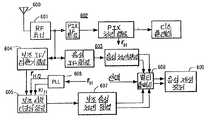
제6도는 TV 신호의 잔류 측파대에 전송되는 보조 신호를 처리하는 회로를 포함하고 있는 수신기의 블록선도.6 is a block diagram of a receiver including circuitry for processing auxiliary signals transmitted to the remaining sidebands of a TV signal.
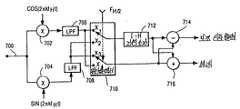
제7도 및 9도는 보조 신호를 복구시키는 또 다른 특정 장치의 블록선도.7 and 9 are block diagrams of another specific device for recovering auxiliary signals.
* 도면의 주요부분에 대한 부호의 설명* Explanation of symbols for main parts of the drawings
10 : 비디오 소스 16 : 잔류 측파대 필터10 video source 16: residual sideband filter
18 : 오디오 소스 30 : 스펙트럼 조정기18: audio source 30: spectrum adjuster
601 : 튜너 602 : 비디오 프로세서601 Tuner 602 Video Processor
606 : 위상 고정 루프 702, 704 : 증배기606: phase locked
710 : 멀티플렉서 712 : 지연 소자710: multiplexer 712: delay element
714 : 감산기 808, 810 : 1-H 콤 필터714:
본 발명은 보조 정보를 텔레비젼 신호에 전송하는 장치에 관한 것이다.The present invention relates to an apparatus for transmitting auxiliary information in a television signal.
본 발명은 전송용 보조(예컨대, 디지탈) 오디오 신호를 표준 텔레비젼 신호와 결합시키는 것에 대해서 설명될 것이지만은 본 발명이 이러한 응용에만 국한되는 것이 아님을 인식해야 할 것이다.Although the present invention will be described in terms of combining transmission auxiliary (eg, digital) audio signals with standard television signals, it should be appreciated that the present invention is not limited to this application.
발명자가 P.R.J. Court 인 미합중국 특허 제 3,231,818 호에, 정상 오디오 캐리어가 가입정보(subscription information)로 인코딩되고 프로그램 음성이 텔레비젼 신호의 잔류 측파대에 위치하는 주파수 변조 캐리어로 제공되는 가입 텔레비젼 시스템이 개시되어 있다. 이 경우에서, 주파수 변조 캐리어는 화상 캐리어보다 낮은 1.0MHz에 위치된다.The inventor of P.R.J. Court U. S. Patent No. 3,231, 818 discloses a subscribing television system in which a normal audio carrier is encoded with subscription information and a program voice is provided as a frequency modulated carrier located in the residual sideband of the television signal. In this case, the frequency modulated carrier is located at 1.0 MHz lower than the picture carrier.
발명자가 R.B. Dome 인 미합중국 특허 제 2,635,140 호에는 청색 화상 신호가 녹색 화상 신호의 잔류 측파대에 위치하는 캐리어로 변조되는 텔레비젼 신호 포맷이 설명되어 있다. 발명자 Dome은 TV 신호의 에너지가 수평 라인 주파수의 정수 배로 스펙트럼 대역에 집중됨을 인식하고 있다. 그는 또한 신호를 효과적으로 분리하기 위해서는 청색 화상 신호를 조절하여 녹색 화상 신호가 점유하고 있는 스펙트럼 대역 사이에 위치되도록 하는 것이 유리함을 인식하고 있다. 청색 화상 신호는 TV 신호이기 때문에, 이 신호의 에너지 역시 라인 주파수의 정수 배로 스펙트럼 대역에 집중된다. 녹색 화상 신호의 스펙트럼 대역 사이에 청색 화상 신호가 위치 되도록 함은 라인 주파수의 1/2의 정수 배로 녹색 화상 신호 캐리어를 위치 시킴으로써 성취된다.The inventors of R.B. Dome US Pat. No. 2,635,140 describes a television signal format in which the blue image signal is modulated with a carrier located in the residual sideband of the green image signal. The inventor Dome recognizes that the energy of the TV signal is concentrated in the spectral band as an integer multiple of the horizontal line frequency. He also recognizes that in order to effectively separate the signal, it is advantageous to adjust the blue picture signal so that it is located between the spectral bands occupied by the green picture signal. Since the blue picture signal is a TV signal, the energy of this signal is also concentrated in the spectral band at an integer multiple of the line frequency. Positioning the blue image signal between the spectral bands of the green image signal is accomplished by positioning the green image signal carrier at an integer multiple of 1/2 of the line frequency.
TV 신호와 결합되는 보조 신호(예컨대, 음성신호)를 효과적으로 분리시키기 위해서는, 보조 신호 에너지가 TV 신호의 스펙트럼 대역사이에 집중되어야 한다.In order to effectively separate an auxiliary signal (eg, an audio signal) that is combined with a TV signal, the auxiliary signal energy must be concentrated between the spectral bands of the TV signal.
그러나, 아날로그 음성 신호의 에너지 스펙트럼은 전형적으로 20Hz 내지 20KHz인 주파수 대역에 걸쳐 비교적 균일하다. 만일 음성 신호가 디지탈 포맷, 예컨대 2진, 12진 등으로 변환되면, 신호를 나타내는 스펙트럼 대역은 다소 (예컨대, 350KHz) 넓어진다. 라인 주파수의 배수에 위치하는 스펙트럼 대역에서는 이런 과정이 발생되지 않는다.However, the energy spectrum of the analog speech signal is relatively uniform over the frequency band, which is typically 20 Hz to 20 KHz. If the speech signal is converted into a digital format, such as binary, hexadecimal, or the like, the spectral band representing the signal is somewhat widened (e.g., 350 KHz). This process does not occur in spectral bands located at multiples of the line frequency.
본 발명의 실시예는 보조 신호의 에너지가 신호 정보 내용의 손실하지 않고 스펙트럼 대역에 집중되도록 조절하는 방법 및 장치를 예시한다.Embodiments of the present invention illustrate a method and apparatus for adjusting the energy of an auxiliary signal to be concentrated in the spectral band without losing signal information content.
본 발명은 보조 신호를, 보조 신호의 상호 배타적인 부분을 부분적으로 포함하고 있는 두개의 중간 신호로 배분함과 더불어 상기 신호의 부분을 극성 반전시킨다. 또한, 본 장치는 비디오 신호의 라인 주파수의 배수인 주파수를 갖는 캐리어를 직각 위상 변조시킨다. 이 직각 위상 변조 신호는 그후 전송을 위해서 TV 신호와 결합된다.The present invention distributes the auxiliary signal into two intermediate signals that partially include mutually exclusive portions of the auxiliary signal, as well as polarizes the portion of the signal. The apparatus also quadrature phase modulates a carrier having a frequency that is a multiple of the line frequency of the video signal. This quadrature phase modulated signal is then combined with the TV signal for transmission.
본 발명의 또 다른 실시예에서, TV 신호로 전송되는 보조 신호 검출 장치는 수신 신호를 검출하여 베이스밴드 보조 신호를 발생시킨다. 이 베이스밴드 보조 신호는 90°의 위상 관계를 가지며 라인 주파수의 배수인 주파수를 갖는 두개의 신호로 증배된다. 증배된 부분은 라인 간격의 정수만큼 지연되고, 지연된 증배 부분과 비지연된 증배 부분이 결합되어, 복구된 디코딩된 보조 신호가 형성된다.In another embodiment of the present invention, the auxiliary signal detection apparatus transmitted as a TV signal detects the received signal to generate a baseband auxiliary signal. This baseband auxiliary signal is multiplied by two signals having a phase relationship of 90 ° and having a frequency that is a multiple of the line frequency. The multiplied portion is delayed by an integer number of line intervals, and the delayed multiplied portion and the non-delayed multiplied portion are combined to form a recovered decoded auxiliary signal.
이제 첨부한 도면에 의거하여 본 발명을 상세히 설명하기로 한다.The present invention will now be described in detail with reference to the accompanying drawings.
제1도는 NTSC 방식에 있어서 6MHz의 대역으로 제한되는 방송 텔레비젼 신호의 신호 스펙트럼을 도시하고 있다. 보조 캐리어 및 이것의 측파대를 무시하는 텔레비젼 신호는 비디오 캐리어로 변조되는 명도, 색도 및 동기 성분을 포함한다. 변조된 캐리어는 직각 측파대 필터링되어, 비디오 캐리어 하부의 대략 0.75KHz에서 저 측파대의 신호 주파수를 제거한다. 음성 캐리어는 비디오 신호에 부가되어 비디오 신호의 상부 극단에 머무르게 된다. 직각 측파대 스펙트럼에 위치된 텔레비젼 신호 성분은 주로 수평 라인 주파수의 정수 배의 중앙에 위치된 스펙트럼 대역에 집중되는 저주파수의 명도 성분으로 이루어진다.1 shows the signal spectrum of a broadcast television signal limited to the 6 MHz band in the NTSC system. A television signal that ignores the secondary carrier and its sidebands includes brightness, chromaticity, and synchronization components that are modulated with the video carrier. The modulated carrier is quadrature sideband filtered to remove the signal frequency of the low sideband at approximately 0.75 KHz below the video carrier. The voice carrier is added to the video signal and stays at the upper extreme of the video signal. Television signal components located in the right sideband spectrum consist primarily of low frequency brightness components concentrated in the spectral band located in the center of an integer multiple of the horizontal line frequency.
본 발명에 따르면, 부가되는 신호는 예컨대, 비디오 캐리어 하부의 대략 0.75NHz에 집중되어 나타나는 보조 캐리어이다. 보조 캐리어의 측파대는 명도 성분이 점유하고 있는 스펙트럼 대역 사이에서 발생하도록 조절된다. 본 도면에서, 보조 신호의 대역폭은 적어도 500KHz의 정보 대역폭을 제공하는 보조 캐리어의 각 사이드에서 대략 500KHz로 신장된다. 본 예에서, 보조 신호는 250KHz로 비디오 캐리어로부터 분리되어 이들과의 간섭을 방지한다. 이러한 공간 또는 보호 주파수대는 보조 신호가 인터캐리어 음성 검출 시스템을 갖는 수신기의 오디오 신호에서 바람직하지 못한 간섭을 야기하지 못하도록 한다.According to the invention, the added signal is, for example, an auxiliary carrier which appears concentrated at approximately 0.75 NHz below the video carrier. The sidebands of the secondary carriers are adjusted to occur between the spectral bands occupied by the lightness component. In this figure, the bandwidth of the auxiliary signal is stretched to approximately 500KHz on each side of the auxiliary carrier providing at least 500KHz information bandwidth. In this example, the auxiliary signal is separated from the video carrier at 250 KHz to prevent interference with them. This spatial or guard band prevents the auxiliary signal from causing undesirable interference in the audio signal of the receiver with the intercarrier speech detection system.
제2도는 본 발명의 실시예를 개략적으로 예시한 것이다. 본 실시예의 시스템에 있어서, 본 발명은 전송용 보조 음성 신호를 TV 신호로 엔코딩하는 단계를 포함하고 있다. 그러나, 본 발명은 전송용 수평 라인 주파수의 정수 배로 집중된 에너지를 갖지 못하는 신호를 TV 신호로 엔코딩 하는데도 활용될 수 있음을 이해해야 할 것이다.2 schematically illustrates an embodiment of the invention. In the system of this embodiment, the present invention includes the step of encoding a transmission auxiliary audio signal into a TV signal. However, it should be understood that the present invention can also be utilized to encode a signal that does not have energy concentrated to an integer multiple of the horizontal line frequency for transmission into a TV signal.
제2도에서, 소자들(10 내지 26)은 표준 TV 신호를 발생 및 전송시키는 표준 TV 신호 엔코더를 구성한다. 텔레비젼 카메라 일 수 있는 비디오 소스(10)로부터 나오는 비디오 신호가 비디오 프로세서(12)에 인가된다. 비디오 프로세서(12)는 동기 성분이 포함된 베이스 밴드 합성 비디오 신호를 발생시켜 RF 변조기(14)에 인가하며, RF 변조기(14)는 상기 합성 비디오 신호 진폭에 응답하여 무선 주파수 비디오 캐리어를 진폭 변조시킨다. 변조된 비디오 캐리어는, 제1도에 도시된 스펙트럼과 일치되도록 상기 변조 신호의 주파수 성분을 제한하는 잔류 측파대 필터(16)에 인가된다.In FIG. 2,
오디오 소스(18)로부터의 오디오 신호는 음성 프로세서(20)에 인가된다. 이 프로세서(20)는 전송에 앞서 오디오 신호를 미리 조절하기 위해 비교 회로 또는 다른 종래의 회로를 포함하고 있다. 음성 프로세서(20)로부터의 미리 조절된 오디오 신호는 RF 변조기(22)에 인가되는데, 여기서 RF 변조기(22)는 주파수가 4.5MHz(NTSC)인 캐리어를 화상 캐리어 주파수 이상으로 주파수 변조시킨다. 잔류 측파대 필터(16)로부터의 변조 합성 신호 및 변조기(22)로부터의 변조 음성 신호는 보조 신호가 없는 경우 표준 TV 방송 신호를 형성하는 신호 결합기(24)에 인가된다.The audio signal from the
오디오 소스(18)로부터의 오디오 신호는 또한 디지탈화기(digitizer) 겸 프로세서(28)에 인가되는데, 여기서 상기 오디오 신호(또는 스테레오 신호의 경우에 있어서의 신호)는 순차적인 형태로 디지탈화 및 포맷된다. 프로세서(28)에 의해 제공된 상기 신호는 2진 비트스트림, 12진 비트스트림 등으로 포맷된다.The audio signal from the
이렇게 포맷된 상기 신호는 스펙트럼 조정기(30)에 인가되는데, 여기서 스펙트럼 조정기(30)는 인가 신호의 에너지를 라인 주파수의 1/2의 홀수 배의 중앙에 위치하는 스펙트럼 대역에 집중시킨다. 스펙트럼 조정기(30)로부터의 신호는 변조기(32)에 인가되며, 이 변조기(32)는 비디오 캐리어 신호에 응답하여 단일의 측파대 변조 캐리어를 발생한다. 변조기(32)의 출력은 주파수가 비디오 캐리어의 주파수 보다 작은 대략 0.75MHz이며, 보조 신호로 변조되는 캐리어이다. 변조기(32)로부터의 신호는 결합기(24)에 인가되는데, 여기서 상기 신호는 변조된 합성 비디오 신호와 부가적으로 결합된다.The signal thus formatted is applied to a
제3도는 제2도에 도시된 스펙트럼 조정기(30)의 제1실시예이다. 제3도(및 제4도)의 회로는 3개의 동작신호, 즉 1) 1/2 라인 주파수의 구형파 신호(FH/2), 2) 주파수 ω= 2πkfH의 코사인 신호 (여기서, k는 정수이고 그리고 fH는 신호 FH의 주파수에 대응한다). 3) 주파수 ω= 2πkfH의 사인 신호를 필요로 한다. 이들 3개의 신호는 비디오 프로세서(12)가 제공하는 수평동기 신호 FH에 응답하는 통상적인 위상 고정 루프(PLL)회로(31) (제2도에 도시됨)에 의해 발생된다.3 is a first embodiment of the
제3도에서, 입력 신호가 멀티플렉싱 회로(301)에 결합되는데, 이 회로(301)는 신호 FH/2에 응답하여 그 입력 신호를 1 수평 라인 간격 주기동안 연결부 01 및 02에 결합시킨다. 연결부 01에 인가된 신호는 1 수평 라인 간격 지연 소자(302)의 입력 연결부 및 감산기(304)의 피감수(被減數) 입력 연결부에 결합된다. 지연소자(302)의 출력 연결부는 감산기(304)의 감수 입력 연결부에 결합된다. 입력 신호가 연결부 01에 결합되기 전의 1 수평 라인 간격동안, 연결부 01에는 어떠한 신호도 결합되지 않는다. 그러므로, 신호가 연결부 01에 인가되는 각 라인 간격의 시점에서는 지연소자(302)가 어떠한 데이타도 포함하지 못한다. 따라서, 신호가 연결부 01에 결합되는 라인 간격 동안에는 지연소자(302)가 감산기(304)에 어떠한 신호도 인가시키지 못하며, 연결부 01에 인가된 신호는 변화됨이 없이 감산기(304)를 통과한다. 이 라인 간격 동안에는 데이타가 지연소자(302)내로 로딩되는 한편 다음 라인 간격 동안에는 지연소자(302)의 출력에 나타난다. 그러나, 상기한 다음 라인 간격 동안에는 입력 신호가 연결부 01에 연결되지 않으므로 단지 지연 소자(302)에 의해서 제공되는 신호만이 감산기(304)에 결합된다. 이 신호는 감산기(304)에 의해 극성이 반전된 상태로 출력된다. 감산기(304)의 출력은 제4도에서 S1로 표시했다. 신호의 또 다른 수평 라인 주기가 지연소자(303) 및 감산기(305)에 의해서 상기와 마찬가지 방식으로 처리된다. 감산기(305)에 의해 제공되는 출력 신호가 제4도에서 S2로 표시되어있다.In FIG. 3, an input signal is coupled to the
제4도에서, FH로 표시된 파형은 수평 동기 신호를 나타내며 입력으로 표시된 블록열은 보조 신호를 나타낸다. 각 블록(A, B, C, 등)은 신호 정보의 수평 라인 간격을 나타낸다. 블록열로 나타낸 신호 S1및 S2는 각기 다른 입력 신호선으로부터의 신호 정보를 포함한다. 신호 S1및 S2가 결합될 때, 이 결합 신호의 용장도(redundancy)가 100 퍼센트가 됨을 알 수 있을 것이다. 주목할 사항으로, 상기 두개의 신호 경도에 있는 소자들이 전대역 신호들을 통과시킨다. 모든 시간에서, 한 경로 또는 다른 경로를 통해서 신호가 결합되면 정보의 손실이 일어나지 않는다. 또한, 지연 소자와 감산기의 결합은 감산 1-H 콤 필터의 형태를 띠게 되는 데, 이 필터는 공지된 바와 같이 라인 주파수의 1/2의 홀수 배로 중앙에 위치되는 스펙트럼 대역에서 신호 에너지를 통과시킨다.In FIG. 4, the waveform indicated by FH represents the horizontal synchronizing signal and the block string indicated as the input represents the auxiliary signal. Each block (A, B, C, etc.) represents a horizontal line spacing of signal information. Signals S1 and S2 , represented in block columns, contain signal information from different input signal lines. It will be appreciated that when the signals S1 and S2 are combined, the redundancy of this combined signal is 100 percent. Note that the elements at the two signal gradients pass the full-band signals. At all times, there is no loss of information when signals are combined through one path or the other. In addition, the combination of the delay element and the subtractor takes the form of a subtracted 1-H comb filter, which, as is known, passes signal energy in a centrally located spectral band at an odd multiple of half the line frequency. .
감산기(304)로부터의 신호 S1이 증배기(306)에 결합되고, 일정 주파수 kfH를 갖는 캐리어 신호로 증배된다. 감산기(305)로부터의 신호 S2는 증배기(307)에 결합되고, 일정주파수 kfH를 갖지만 증배기(306)에 인가되는 캐리어 신호에 비해서 위상으로부터 90°로 벗어나는 캐리어 신호로 증배된다. 증배기(306) 및 (307)로부터의 출력신호는 가산기(308)에 의한 합산으로 직각 변조 출력신호 형태가 되어 변조기(32)에 인가된다(제2도).Signal S1 from
제5도는 제3도 회로와 같은 기능을 수행하지만 하드웨어가 삭감된 또 다른 회로를 예시한 것이다. 제5도에서, 입력이 연결부(500)에 인가되고 이 연결부터 나와서 1 수평 라인 주기 지연소자(501) 및 스위칭 회로(503)의 입력 연결부 X1 및 X4에 결합된다. 지연 소자(501)로부터의 지연 신호는 인버터(502)에 의해서 극성이 반전되어 스위칭 회로(503)의 입력 연결부 X2 및 X3에 결합된다. 스위칭 회로(503)는 주파수가 fH/2 인 동작 신호에 응답하여, 일련의 라인 간격 동안 입력 연결부 X1 및 X2를 출력 연결부 S1에 교대로 결합시킨다. 스위칭 회로(503)는 또한 일련의 라인 간격동안 입력 연결부 X3 및 X4를 출력 연결부 S2에 교대로 결합시킨다. 출력 연결부에서의 신호 S1및 S2는 제4도의 신호 S1및 S2에 각각 대응한다. 연결부로부터의 신호 S1및 S2는 소자(306, 307 및 308)내의 주파수가 kfH인 캐리어 신호를 직각 변조시키며, 상기 소자들의 출력은 변조기(32)에 인가된다(제2도).Figure 5 illustrates another circuit that performs the same function as the circuit of Figure 3 but with reduced hardware. In FIG. 5, an input is applied to the
주파수가 kfH인 캐리어 신호는 비디오 신호의 수평주파수로 위상고정되고 그리고 멀티플렉서 또는 스위칭 회로(301, 503)에 인가되는 주파수가 FH/2 인 동작 신호 역시 수평주파수로 위상 고정된다. fH/2 로의 스위칭 및 감산 콤 필터의 기능에 기인하여, 처리되는 보조 신호의 에너지가 라인 주파수의 1/2의 홀수 배를 갖는 스펙트럼 대역에 이르게된다. 신호 S1및 S2를 주파수 kfH로 변조시킴으로써, 신호 스펙트럼이 수평 주파수의 정수 배로 변형(translate)된다. k = 47인 경우, 상기 스펙트럼은 주파수가 약 0.75MHz로 상향 변형된다. 상기 변형된 신호가 비디오 캐리어로 변조되는 단일의 측파대(저대역) 신호인 경우, 보조 신호 캐리어는 비디오 캐리어 이하의 kfH에 위치되며, 상기 보조 상기 신호들을 부가적으로 결합시킴으로써 명도 성분과 주파수 인터리브(frequency interleave)된다.The carrier signal of frequency kfH is phase locked to the horizontal frequency of the video signal and the operating signal of the frequency FH / 2 applied to the multiplexer or switching
제6도는 보조 신호를 표준 TV 신호로 전송하는 시스템의 수신단을 도시한 것이다. 이 보조 신호는 음성 신호로 가정된다. 제6도에서, 전송신호는 안테나(600)에 의해 수신되어 튜너(601)에 결합된다. 튜너(601)로부터의 RF 신호는 화상 디스플레이를 발생시키는 종래의 비디오 프로세서(602)에 인가된다. 주목할 사항으로, 잔류 측파대에 놓이는 보조 신호가 종래의 화상 IF 회로의 나이키스트 필터 함수에 의해 실질적으로 감쇄되어 화상 처리와 간섭하지 않는다.6 shows a receiving end of a system for transmitting an auxiliary signal as a standard TV signal. This auxiliary signal is assumed to be a voice signal. In FIG. 6, the transmitted signal is received by
상기 튜너로부터의 RF 신호는 종래의 음성 처리회로(603)에 결합되는데, 이 회로는 통상의 방식으로 전송되는 음성 신호를 추출 및 처리한다. 상기 회로(603)로부터의 오디오 신호는 멀티플렉서(608)에 인가되며, 이 멀티플렉서의 출력은 음성 재생 장치(609)에 결합된다. 음성 재생 장치(609)는 증폭기 및 스피커를 포함하고 있다. 멀티플렉서(608)에 인가되는 또 하나의 신호는 보조 음성 신호로써, 이 신호는 정상적인 조건에서 그리고 디지탈 신호인 경우 통상적으로 전송되는 음성 신호보다 양호도(quality)가 높은 것으로 여겨진다. 멀티플렉서(608)는 수신기를 사용하는 사용자의 수동동작에 의해서 제공되거나 또는 예컨대, 보조신호, 통상의 음성신호 또는 이들 모두의 신호/잡음비의 함수로써 내부적으로 발생되는 선택(SELECT) 신호에 의해서 제어된다.The RF signal from the tuner is coupled to conventional
튜너(601)로부터의 RF 신호는 전송 신호의 잔류 측파대에 응답하도록 된 보조 IF/검출기 회로(604)에 결합된다. 상기 회로(604)는 예컨대 비디오 캐리어를 직각위상(quadrature) 검출함으로써, 베이스밴드 직각 변조 보조신호를 발생시킨다.The RF signal from
이 베이스밴드 보조신호는 위상 고정 루프 회로(606)가 제공하는 주파수가 fH/2 및 kfH인 신호에 응답하는 베이스밴드 보조신호 디코딩 회로(605)에 의해 디코딩된다. 상기 디코드 보조 신호는 보조 신호 처리회로(607)에 의해 처리되어 멀티플렉서(608)에 결합된다. 상기 처리 회로(607)는 예컨대, 12진 신호를 병렬 스테레오 신호로 디코딩하는 회로 및 D/A 변환기 등을 포함하고 있다.This baseband auxiliary signal is decoded by a baseband auxiliary
베이스밴드 보조 신호 디코딩 회로(605)의 예가 제7도에 예시되어 있다. IF/검출기 회로(604)로부터의 베이스밴드 보조 신호는 연결부(700)에 인가되고 다시 증배기(702, 704)에 결합된다. 이 보조 신호는 증배기(702, 704)에서 위상 고정 루프 회로(606)가 제공하는 주파수 kfH의 신호 및 직각 위상으로 증배된다. 증배기(702)로부터의 출력 신호는 저역 필터(706)에 인가되며, 이 필터(706)의 출력은 멀티플렉서(710)의 입력 연결부 X2 및 X3에 결합된다. 저역 필터(706, 708)의 대역폭은 신호 S1및 S2의 주파수 성분을 통과시키는 정도로 해서 적어도 kfH와 실질적으로 같게 선택된다. ω= 2πkfH이면, 수신 베이스밴드 보조신호 S (t)는 식 S (t) = S1(t) cos ωt + S2(t) sin ωt로 표시될 수 있다. 증배기(702)에 의해 제공되는 증배값은 S1(t) cos2ωt + S2(t) cos ωt sin ωt 와 같게 되는데, 이 값은 삼각 항등식을 이용하여 S1(t)/ 2 -S1(t) cos2ωt/2 + S2(t) sin2ωt/2 로 변환될 수 있다. 상기 식에서 첫 번께 항은 필터(706)에 의해 통과된다. 상기와 마찬가지의 분석으로, 저역 필터(708)에 의해 제공되는 신호가 S2(t)/2와 동일하게 됨을 알 수 있을 것이다.An example of the baseband auxiliary
멀티플렉서(710)는 수평 라인 주파수의 1/2로 신호 S1/2 및 S2/2를 1 수평 주기 지연소자(712)에 교대로 결합시키고 신호 S2/2 및 S1/2를 가산기(716)와 감산기(714)의 각각의 제1 입력 연결부에 교대로 결합시킨다. 지연소자(712)의 출력은 감산기(714)와 가산기(716)의 각각의 제2 입력 연결부에 결합된다.The
제4도에서, 지연소자(712)에 인가되는 신호는 S3으로 표시되어 있고, 가산기(716) 및 감산기(714)의 제1 입력 연결부에 인가되는 신호는 S4로 표시되어 있다. 지연소자(712)의 출력은 ODE로 표시된다. 가산기와 감산기의 출력 신호는 각각 ADD 및 SUB로 표시된다. 감산기(714)의 출력은 디코드 보조 신호로서, 반대 극성의 용장 신호를 평균화함으로써 형성된다. 주목할 사항으로, 1/2의 인자로 감쇄되는 보조 신호는 멀티플렉서(710)에 의해서 직접(S3또는 S4로) 택해질 수 있지만, 감산기(714)에 의해 제공되는 상기 평균화된 신호가 잡음이 존재하는 경우에 보다 더 정확해질 수가 있다.In FIG. 4, the signal applied to the
만일 신호가 에러 없이 전송되면, 가산기(716)의 출력은 영(0)이 된다. 가산기(716)의 출력이 영(0)이 아니면, 이는 전송 에러를 나타난다. 가산기(716)의 출력은 감지되고 그리고 예컨대 정확한 동작 또는 조정처리를 위한 제어신호를 제공하도록 임계값(threshold) 검출된다. 예컨대, 가산기(716)로부터의 임계값 검출된 임계값 검출 신호는 멀티플렉서(608)의 SELECT 제어를 제공하는데 활용된다(제6도). 만일 가산기 (716)로부터의 에러신호의 레벨이 소정 레벨을 초과하는 경우, 임계값 검출에 의해서 제어 신호가 발생된다.If the signal is transmitted without error, then the output of
제8도는 제2도에서 소자(30)로 실시된 부가되는 보조신호 스펙트럼 조절기 회로를 예시한 것이다. 제9도는 제6도에서 소자(605)로 실시된 인버터 회로를 예시한 것이다.FIG. 8 illustrates the additional auxiliary signal spectrum regulator circuit implemented with
제8도에서, 각주파수 ω은 ω = 2πnfH/4로 명시되는데, 여기서 n은 작은 홀수 정수이다. 각주파수 ωo는 ωo= 2π(P-kfH)로 명시되는데, 여기서 P는 비디오 캐리어의 주파수이다. 4개의 동작신호 cos(ωt), sin(ωt), cos(ωot) 및 sin(ωot)가 전송용 보조 신호를 발생시키는데 있어서 필요하게 된다. 이들 신호들은 수평동기 신호 FH및 비디오 캐리어에 응답하는 위상 고정루프 회로(800) 및 믹서(802)에 의해 통상의 방식으로 발생된다.In FIG. 8, the angular frequency ω is specified as ω = 2πnfH / 4, where n is a small odd integer. Angular frequency ωo is specified as ωo = 2π (P-kfH ), where P is the frequency of the video carrier. Four operation signals cos (ωt), sin (ωt), cos (ωo t) and sin (ωo t) are needed to generate an auxiliary signal for transmission. These signals are generated in a conventional manner by the phase locked
보조신호 S(t)는 두개의 증배기 회로(804, 806) 각각의 입력 연결부에 인가된다. 이 신호 S(t)는 예컨대 주파수가 fH/4인 직각 위상 캐리어로 증배된다. 주목할 사항으로, 캐리어 주파수는 일반적으로 신호 S(t)의 대역폭 보다 극히 작으며, 따라서 폴드오버(foldover) 또는 얼라이어싱 성분 (aliasing components)이 발생된다. 그러나, 직각 성분이 유효하기 때문에 수신기에서 얼라이어싱 성분이 제거될 수 있다.The auxiliary signal S (t) is applied to the input connection of each of the two
증배기(804, 806)로부터의 증배 신호는 감산 1-H 콤 필터(808, 810)에 각각 결합된다. 상기 콤 필터(808, 810)는 각각 방정식Multiplication signals from
Sa= S(t) cos(ωt) - S(t-H) cosω(t-H)Sa = S (t) cos (ωt)-S (tH) cosω (tH)
Sb= S(t) sin(ωt) - S(t-H) sinω(t-H)Sb = S (t) sin (ωt)-S (tH) sinω (tH)
로 명시되는 신호 Sa및 Sb를 각각 발생시킨다.Generate signals Sa and Sb , respectively.
그러나, cosω(t-H) = sin (ωt) 이고 sinω(t-H) = cos (ωt)이므로, Sa및 Sb는However, since cosω (tH) = sin (ωt) and sinω (tH) = cos (ωt), Sa and Sb are
Sa= S(t) cos(ωt) - S(t-H) sin(ωt)Sa = S (t) cos (ωt)-S (tH) sin (ωt)
Sb= S(t) sin(ωt) + S(t-H) cos(ωt)로 다시 나타내지게 된다. 신호 Sa및 Sb는 증배기 회로(812, 814)에 각각 결합되어, 여기서 각 주파수 ωo의 직각위상 관련신호로 증배된다. 증배기(812, 814)로부터의 증배 신호는 가산기(816)에 의해 합산되며, 이 가산기는 변조된 잔류 측파대 비디오 신호에 직접 부가되는 변조 캐리어 Ss를 발생시킨다. 상기 신호 Ss는 방정식Sb = S (t) sin (ωt) + S (tH) cos (ωt). Signals Sa and Sb are coupled to
Ss = Sacos(ωot) + Sbsin(ωot)으로 명시된다.Ss = Sa cos (ωo t) + Sb sin (ωo t).
수신기(제9도)의 보조 신호 디코더는 S5내지 S8로 표시되는 4개의 동작 신호The auxiliary signal decoder of the receiver (Fig. 9) has four operation signals represented by S5 to S8 .
S5= cos(ωt) cos(ωot)S5 = cos (ωt) cos (ωo t)
S6= sin(ωt) sin(ωot)S6 = sin (ωt) sin (ωo t)
S7= -sin(ωt) cos(ωot)S7 = -sin (ωt) cos (ωo t)
S8= cos(ωt) sin(ωot)S8 = cos (ωt) sin (ωo t)
를 필요로 한다. 여기서, 각주파수 ω 및 ωo는 제8도와 관계하여 명시한 것과 같다. 이들 4개의 신호는 수평동기 신호 F 및 비디오 캐리어에 응답하는 신호 발생기(900)에 의해서 통상의 방식으로 발생된다.Need. Here, the angular frequencies ω and ωo are as specified in relation to FIG. These four signals are generated in a conventional manner by the
수신기에서, 튜너로부터의 RF 신호는 (잔류 측파대를 통과하도록) 바이패스 필터링되어, 보조 신호 디코더 입력 연결부(901)에 결합된다. 이 신호는 증배기(902, 904, 906 및 908) 각각의 입력 연결부에 인가되어 신호 S5, S6, S7및 S8로 각각 증배된다. 증배기(902, 904, 906, 및 908)에 의해서 발생된 증배 신호는 저역 필터(910, 912, 914, 및 916)에 각각 결합된다. 저역 필터(910 내지 916)는 각 주파수 보다 더 큰 신호주파수를 감쇄시킨다. 상기 필터들의 설계에 있어서의 장애요인은 이들 필터들이 신호 S(t) cos2ωt에 포함된 신호 주파수들을 통과시킨다는 점이다.At the receiver, the RF signal from the tuner is bypass filtered (to pass through the residual sideband) and coupled to the auxiliary signal
저역 필터(910, 912)로부터의 출력 신호는 가산기(918)에 결합된다. 가산기(918)에 의해 제공되는 합신호 S9는 S9= 1/2[S(t) cos2ωt - S(t-H) sinωt cos ωt + S(t)sin2ωt + S(t-H)sinωt cosωt]로서, 이를 간단히 하면The output signal from the low pass filters 910, 912 is coupled to the
S9= 1/2 S(t) [cos2ωt + S(t) sin2ωt], 또는S9 = 1/2 S (t) [cos2 ωt + S (t) sin2 ωt], or
S9= 1/2 S(t) [cos2ωt + sin2ωt] = S(t)/2 이 된다.S9 = 1/2 S (t) [cos2 ωt + sin2 ωt] = S (t) / 2.
저역 필터(914)로부터의 출력 신호는 가산기(990)에 결합되는 바, 이 가산기(990)는 신호 S10, 즉 S10= S(t-H)/2을 발생시킨다.The output signal from the low pass filter 914 is coupled to an adder 990, which generates a signal S10 , S10 = S (tH) / 2.
신호 S9는 1 수평 라인 지연소자(922)에 결합되며, 상기 지연소자(922)는 신호 S9= S(t)/2를 지연시키는 한편 지연 신호 S9' = S(t-H)/2를 발생시킨다. 신호 S9'는 가산기(924)와 감산기(926) 각각의 제1 입력 연결부에 결합된다. 신호 S10은 가산기(924)와 감산기(926) 각각의 제2 입력 연결부에 결합된다. 가산기(924)는 1 라인 간격 지연된 요망신호와 등가의 신호 S(t-H)를 발생시킨다. 감산기(926)는 전송 에러가 발생할 때(이 경우에, 감산기는 에러신호를 발생시킨다)를 제외하고는 영(0)값의 신호를 발생시킨다.Signal S9 is coupled to one horizontal
주목할 사항으로, 제9도에서 저역 필터(910 내지 916)가 제거될 수 있으며, 가산기(918, 920)뒤에 2개의 유사한 저역 필터가 삽입될 수 있다.Note that the low pass filters 910-916 can be removed in FIG. 9, and two similar low pass filters can be inserted after the
특허청구의 범위에서, 거의 연속적인 주파수 스펙트럼을 갖는 것으로 명시되는 신호는 그 에너지가 비디오 신호의 수평 주파수 간격에 집중되지 않는 신호를 의미하며 그리고 사실은 연속적인 주파수 스펙트럼을 갖지 않는다. 다시 말해서, 그 스펙트럼에서 홀 및/또는 피크를 갖는다.In the claims, a signal specified as having a nearly continuous frequency spectrum means a signal whose energy is not concentrated in the horizontal frequency interval of the video signal and in fact does not have a continuous frequency spectrum. In other words, it has holes and / or peaks in its spectrum.
Claims (10)
Translated fromKoreanApplications Claiming Priority (3)
| Application Number | Priority Date | Filing Date | Title |
|---|---|---|---|
| JP392,500 | 1989-08-11 | ||
| US392,500 | 1989-08-11 | ||
| US07/392,500US5063446A (en) | 1989-08-11 | 1989-08-11 | Apparatus for transmitting auxiliary signal in a TV channel |
Publications (2)
| Publication Number | Publication Date |
|---|---|
| KR910005686A KR910005686A (en) | 1991-03-30 |
| KR0183015B1true KR0183015B1 (en) | 1999-05-01 |
Family
ID=23550840
Family Applications (1)
| Application Number | Title | Priority Date | Filing Date |
|---|---|---|---|
| KR1019900012261AExpired - Fee RelatedKR0183015B1 (en) | 1989-08-11 | 1990-08-10 | Apparatus for transmitting auxiliary signal in a tv channel |
Country Status (7)
| Country | Link |
|---|---|
| US (1) | US5063446A (en) |
| JP (1) | JP2657576B2 (en) |
| KR (1) | KR0183015B1 (en) |
| CA (1) | CA2021093A1 (en) |
| DE (1) | DE4024806A1 (en) |
| FR (1) | FR2651630B1 (en) |
| GB (1) | GB2237474B (en) |
Families Citing this family (88)
| Publication number | Priority date | Publication date | Assignee | Title |
|---|---|---|---|---|
| US5550579A (en)* | 1986-05-14 | 1996-08-27 | Radio Telecom & Technology, Inc. | Two-way cable tv conversion system |
| US5357284A (en)* | 1990-03-29 | 1994-10-18 | Dolby Laboratories Licensing Corporation | Compatible digital audio for NTSC television |
| US5387941A (en)* | 1991-06-14 | 1995-02-07 | Wavephore, Inc. | Data with video transmitter |
| US5410360A (en)* | 1991-06-14 | 1995-04-25 | Wavephore, Inc. | Timing control for injecting a burst and data into a video signal |
| US5617148A (en)* | 1991-06-14 | 1997-04-01 | Wavephore, Inc. | Filter by-pass for transmitting an additional signal with a video signal |
| US5559559A (en)* | 1991-06-14 | 1996-09-24 | Wavephore, Inc. | Transmitting a secondary signal with dynamic injection level control |
| US5831679A (en)* | 1991-06-14 | 1998-11-03 | Wavephore, Inc. | Network for retrieval and video transmission of information |
| US5327237A (en)* | 1991-06-14 | 1994-07-05 | Wavephore, Inc. | Transmitting data with video |
| US5153723A (en)* | 1991-07-24 | 1992-10-06 | Zenith Electronics Corporation | HDTV audio subsystem with timing characteristics compatible with video subsystem |
| US5721788A (en) | 1992-07-31 | 1998-02-24 | Corbis Corporation | Method and system for digital image signatures |
| US6301369B2 (en) | 1992-07-31 | 2001-10-09 | Digimarc Corporation | Image marking to permit later identification |
| US5534933A (en)* | 1993-10-26 | 1996-07-09 | Samsung Electronics Co., Ltd. | Apparatus for processing NTSC TV signals having digital signals on quadrature-phase video carrier |
| US5841886A (en)* | 1993-11-18 | 1998-11-24 | Digimarc Corporation | Security system for photographic identification |
| US6449377B1 (en) | 1995-05-08 | 2002-09-10 | Digimarc Corporation | Methods and systems for watermark processing of line art images |
| US5748783A (en)* | 1995-05-08 | 1998-05-05 | Digimarc Corporation | Method and apparatus for robust information coding |
| USRE40919E1 (en)* | 1993-11-18 | 2009-09-22 | Digimarc Corporation | Methods for surveying dissemination of proprietary empirical data |
| US6611607B1 (en) | 1993-11-18 | 2003-08-26 | Digimarc Corporation | Integrating digital watermarks in multimedia content |
| US5862260A (en)* | 1993-11-18 | 1999-01-19 | Digimarc Corporation | Methods for surveying dissemination of proprietary empirical data |
| US6614914B1 (en) | 1995-05-08 | 2003-09-02 | Digimarc Corporation | Watermark embedder and reader |
| US5768426A (en)* | 1993-11-18 | 1998-06-16 | Digimarc Corporation | Graphics processing system employing embedded code signals |
| US5636292C1 (en)* | 1995-05-08 | 2002-06-18 | Digimarc Corp | Steganography methods employing embedded calibration data |
| US6408082B1 (en) | 1996-04-25 | 2002-06-18 | Digimarc Corporation | Watermark detection using a fourier mellin transform |
| US5822436A (en) | 1996-04-25 | 1998-10-13 | Digimarc Corporation | Photographic products and methods employing embedded information |
| US6757406B2 (en) | 1993-11-18 | 2004-06-29 | Digimarc Corporation | Steganographic image processing |
| US5710834A (en)* | 1995-05-08 | 1998-01-20 | Digimarc Corporation | Method and apparatus responsive to a code signal conveyed through a graphic image |
| US7044395B1 (en) | 1993-11-18 | 2006-05-16 | Digimarc Corporation | Embedding and reading imperceptible codes on objects |
| US5748763A (en)* | 1993-11-18 | 1998-05-05 | Digimarc Corporation | Image steganography system featuring perceptually adaptive and globally scalable signal embedding |
| US7171016B1 (en) | 1993-11-18 | 2007-01-30 | Digimarc Corporation | Method for monitoring internet dissemination of image, video and/or audio files |
| US6122403A (en)* | 1995-07-27 | 2000-09-19 | Digimarc Corporation | Computer system linked by using information in data objects |
| US6983051B1 (en) | 1993-11-18 | 2006-01-03 | Digimarc Corporation | Methods for audio watermarking and decoding |
| US5832119C1 (en)* | 1993-11-18 | 2002-03-05 | Digimarc Corp | Methods for controlling systems using control signals embedded in empirical data |
| US5841978A (en) | 1993-11-18 | 1998-11-24 | Digimarc Corporation | Network linking method using steganographically embedded data objects |
| US6516079B1 (en) | 2000-02-14 | 2003-02-04 | Digimarc Corporation | Digital watermark screening and detecting strategies |
| ATE287176T1 (en)* | 1993-11-18 | 2005-01-15 | Digimarc Corp | VIDEO WITH HIDDEN IN-BAND DIGITAL DATA |
| US6424725B1 (en) | 1996-05-16 | 2002-07-23 | Digimarc Corporation | Determining transformations of media signals with embedded code signals |
| US6580819B1 (en) | 1993-11-18 | 2003-06-17 | Digimarc Corporation | Methods of producing security documents having digitally encoded data and documents employing same |
| US5563664A (en)* | 1994-01-05 | 1996-10-08 | Samsung Electronics Co., Ltd. | Pre-frame-comb as well as pre-line-comb partial-response filtering of BPSK buried in a TV signal |
| US5448299A (en)* | 1994-01-05 | 1995-09-05 | Samsung Electronics Co., Ltd. | Apparatus for processing BPSK signals transmitted with NTSC TV on quadrature-phase video carrier |
| US6869023B2 (en) | 2002-02-12 | 2005-03-22 | Digimarc Corporation | Linking documents through digital watermarking |
| US7039214B2 (en) | 1999-11-05 | 2006-05-02 | Digimarc Corporation | Embedding watermark components during separate printing stages |
| US6522770B1 (en) | 1999-05-19 | 2003-02-18 | Digimarc Corporation | Management of documents and other objects using optical devices |
| US6968057B2 (en) | 1994-03-17 | 2005-11-22 | Digimarc Corporation | Emulsion products and imagery employing steganography |
| US5621471A (en)* | 1994-05-03 | 1997-04-15 | Microsoft Corporation | System and method for inserting and recovering an add-on data signal for transmission with a video signal |
| US5539471A (en)* | 1994-05-03 | 1996-07-23 | Microsoft Corporation | System and method for inserting and recovering an add-on data signal for transmission with a video signal |
| US6560349B1 (en) | 1994-10-21 | 2003-05-06 | Digimarc Corporation | Audio monitoring using steganographic information |
| DE4439248A1 (en)* | 1994-11-03 | 1996-05-09 | Hoechst Ag | Polyolefin molding compound with reduced tendency to peel |
| DE4441606C1 (en)* | 1994-11-23 | 1996-01-11 | Bayerischer Rundfunk Anstalt D | Transmitting digital data stream |
| US5510845A (en)* | 1994-12-23 | 1996-04-23 | Samsung Electronics Co., Ltd. | Receivers for digital signals buried within the trace and retrace intervals of NTSC television signals |
| FR2731576B1 (en)* | 1995-03-09 | 1997-05-23 | Telediffusion Fse | TELEVISION SIGNAL TRANSMISSION CHAIN COMPRISING A DATA CHANNEL |
| US6760463B2 (en) | 1995-05-08 | 2004-07-06 | Digimarc Corporation | Watermarking methods and media |
| US7486799B2 (en) | 1995-05-08 | 2009-02-03 | Digimarc Corporation | Methods for monitoring audio and images on the internet |
| US6728390B2 (en) | 1995-05-08 | 2004-04-27 | Digimarc Corporation | Methods and systems using multiple watermarks |
| US6721440B2 (en) | 1995-05-08 | 2004-04-13 | Digimarc Corporation | Low visibility watermarks using an out-of-phase color |
| US5619269A (en)* | 1995-06-07 | 1997-04-08 | Zenith Electronics Corporation | Frame sync signal for digital transmission system |
| US6577746B1 (en) | 1999-12-28 | 2003-06-10 | Digimarc Corporation | Watermark-based object linking and embedding |
| US7006661B2 (en) | 1995-07-27 | 2006-02-28 | Digimarc Corp | Digital watermarking systems and methods |
| US6408331B1 (en) | 1995-07-27 | 2002-06-18 | Digimarc Corporation | Computer linking methods using encoded graphics |
| US6788800B1 (en) | 2000-07-25 | 2004-09-07 | Digimarc Corporation | Authenticating objects using embedded data |
| US6965682B1 (en) | 1999-05-19 | 2005-11-15 | Digimarc Corp | Data transmission by watermark proxy |
| US6829368B2 (en) | 2000-01-26 | 2004-12-07 | Digimarc Corporation | Establishing and interacting with on-line media collections using identifiers in media signals |
| US6411725B1 (en) | 1995-07-27 | 2002-06-25 | Digimarc Corporation | Watermark enabled video objects |
| US6381341B1 (en) | 1996-05-16 | 2002-04-30 | Digimarc Corporation | Watermark encoding method exploiting biases inherent in original signal |
| US5949793A (en)* | 1996-07-22 | 1999-09-07 | Cellularvision Technology & Telecommunications, L.P. | Transmission of digital and analog signals in the same band |
| US5903231A (en)* | 1996-12-16 | 1999-05-11 | Vidicast Ltd. | System for encoding base N data using a multi-level coding scheme |
| US6122010A (en)* | 1996-12-16 | 2000-09-19 | Vidicast Ltd. | Television signal data transmission system |
| US5946048A (en)* | 1997-03-12 | 1999-08-31 | Hybrid Networks, Inc. | Network device for handling digital data over a TV channel |
| US5946047A (en)* | 1997-03-12 | 1999-08-31 | Hybrid Networks, Inc. | Network system for handling digital data over a TV channel |
| US6549242B1 (en)* | 1997-04-04 | 2003-04-15 | Harris Corporation | Combining adjacent TV channels for transmission by a common antenna |
| US5909253A (en)* | 1997-12-09 | 1999-06-01 | Sarnoff Corporation | Reducing video crosstalk in a data carrier located within a vestigial sideband of a standard television signal |
| US6804376B2 (en) | 1998-01-20 | 2004-10-12 | Digimarc Corporation | Equipment employing watermark-based authentication function |
| JP2001045085A (en)* | 1999-07-27 | 2001-02-16 | Nippon Telegr & Teleph Corp <Ntt> | Quadrature signal generation circuit and quadrature signal generation method |
| US6625297B1 (en) | 2000-02-10 | 2003-09-23 | Digimarc Corporation | Self-orienting watermarks |
| US6804377B2 (en) | 2000-04-19 | 2004-10-12 | Digimarc Corporation | Detecting information hidden out-of-phase in color channels |
| US7027614B2 (en) | 2000-04-19 | 2006-04-11 | Digimarc Corporation | Hiding information to reduce or offset perceptible artifacts |
| DE10042320A1 (en)* | 2000-08-29 | 2002-03-14 | Trend Network Ag | Procedures for presenting information |
| US20020163598A1 (en)* | 2001-01-24 | 2002-11-07 | Christopher Pasqualino | Digital visual interface supporting transport of audio and auxiliary data |
| CA2470094C (en) | 2001-12-18 | 2007-12-04 | Digimarc Id Systems, Llc | Multiple image security features for identification documents and methods of making same |
| US7694887B2 (en) | 2001-12-24 | 2010-04-13 | L-1 Secure Credentialing, Inc. | Optically variable personalized indicia for identification documents |
| US7728048B2 (en) | 2002-12-20 | 2010-06-01 | L-1 Secure Credentialing, Inc. | Increasing thermal conductivity of host polymer used with laser engraving methods and compositions |
| AU2002364255A1 (en) | 2001-12-24 | 2003-07-15 | Digimarc Id Systems, Llc | Covert variable information on id documents and methods of making same |
| WO2003056507A1 (en) | 2001-12-24 | 2003-07-10 | Digimarc Id Systems, Llc | Systems, compositions, and methods for full color laser engraving of id documents |
| US7824029B2 (en) | 2002-05-10 | 2010-11-02 | L-1 Secure Credentialing, Inc. | Identification card printer-assembler for over the counter card issuing |
| WO2004049242A2 (en) | 2002-11-26 | 2004-06-10 | Digimarc Id Systems | Systems and methods for managing and detecting fraud in image databases used with identification documents |
| US7712673B2 (en) | 2002-12-18 | 2010-05-11 | L-L Secure Credentialing, Inc. | Identification document with three dimensional image of bearer |
| DE602004030434D1 (en) | 2003-04-16 | 2011-01-20 | L 1 Secure Credentialing Inc | THREE-DIMENSIONAL DATA STORAGE |
| US7744002B2 (en) | 2004-03-11 | 2010-06-29 | L-1 Secure Credentialing, Inc. | Tamper evident adhesive and identification document including same |
| JP2007150886A (en)* | 2005-11-29 | 2007-06-14 | Aiphone Co Ltd | Video intercom apparatus |
| IES20060564A2 (en)* | 2006-05-03 | 2006-11-01 | Fotonation Vision Ltd | Improved foreground / background separation |
Family Cites Families (11)
| Publication number | Priority date | Publication date | Assignee | Title |
|---|---|---|---|---|
| BE504631A (en)* | 1950-07-28 | |||
| NL249686A (en)* | 1959-03-23 | |||
| US3231818A (en)* | 1961-11-09 | 1966-01-25 | Paramount Pictures Corp | Audio secrecy system for subscription television |
| US3478166A (en)* | 1963-09-09 | 1969-11-11 | Intern Telemeter Corp | Cryptographic subscription television system with grey sync and dual mode augmenting signals |
| US3842196A (en)* | 1972-10-30 | 1974-10-15 | Hazeltine Research Inc | System for transmission of auxiliary information in a video spectrum |
| US3924060A (en)* | 1974-06-24 | 1975-12-02 | Hazeltine Research Inc | Continuous information add-on system |
| US4051532A (en)* | 1975-06-19 | 1977-09-27 | Matsushita Electric Company Of America | Auxiliary signal processing circuit for television receivers |
| JPS61281696A (en)* | 1985-06-06 | 1986-12-12 | Sony Corp | Transmitting system and magnetic recording device for high quality television signal |
| US4661850A (en)* | 1986-01-31 | 1987-04-28 | Rca Corporation | Progressive scan television system with interlaced inter-field sum and difference components |
| JPS6310986A (en)* | 1986-07-02 | 1988-01-18 | Matsushita Electric Ind Co Ltd | Transmission method for television signal |
| US4882725A (en)* | 1987-01-30 | 1989-11-21 | Hitachi, Ltd. | Multiplex transmission method and apparatus |
- 1989
- 1989-08-11USUS07/392,500patent/US5063446A/ennot_activeExpired - Fee Related
- 1990
- 1990-07-12CACA002021093Apatent/CA2021093A1/ennot_activeAbandoned
- 1990-08-04DEDE4024806Apatent/DE4024806A1/ennot_activeWithdrawn
- 1990-08-09GBGB9017469Apatent/GB2237474B/ennot_activeExpired - Fee Related
- 1990-08-10KRKR1019900012261Apatent/KR0183015B1/ennot_activeExpired - Fee Related
- 1990-08-10FRFR9010272Apatent/FR2651630B1/ennot_activeExpired - Fee Related
- 1990-08-10JPJP2210568Apatent/JP2657576B2/ennot_activeExpired - Lifetime
Also Published As
| Publication number | Publication date |
|---|---|
| DE4024806A1 (en) | 1991-02-14 |
| JP2657576B2 (en) | 1997-09-24 |
| US5063446A (en) | 1991-11-05 |
| FR2651630A1 (en) | 1991-03-08 |
| FR2651630B1 (en) | 1995-03-03 |
| KR910005686A (en) | 1991-03-30 |
| CA2021093A1 (en) | 1991-02-12 |
| GB2237474B (en) | 1993-12-15 |
| GB9017469D0 (en) | 1990-09-26 |
| GB2237474A (en) | 1991-05-01 |
| JPH0377491A (en) | 1991-04-03 |
Similar Documents
| Publication | Publication Date | Title |
|---|---|---|
| KR0183015B1 (en) | Apparatus for transmitting auxiliary signal in a tv channel | |
| US5287180A (en) | Modulator/demodulater for compatible high definition television system | |
| EP0485478B1 (en) | Transmitting auxiliary information in a television signal | |
| US4502078A (en) | Digital television receivers | |
| KR100225828B1 (en) | Video signal encoded with additional detail information | |
| JPH03195284A (en) | Signal synthesizer | |
| KR0176643B1 (en) | Digital Residual Sideband Detector with Bandpass Phase Tracker Using Radar Filter for High Quality Television Receivers | |
| US4908860A (en) | System for the secret transmission of audio signals and television receiver for receiving such signals | |
| JPH01120189A (en) | Extra-fine picture transmisson | |
| JPH0678014A (en) | Television signal processor | |
| US5151779A (en) | Signal transmission system for high definition television | |
| JPH0435391A (en) | Phase correction relationship restoration device for two signals passing through separated paths | |
| JP3640669B2 (en) | Circuit device for derivation of sound quality signal depending on sound quality of received multiplexed signal | |
| US5745635A (en) | Adaptive deemphasis and reemphasis of high frequencies in video tape recording, utilizing a recorded control signal | |
| JPS6376592A (en) | Multiplex transmission signal reproducing device | |
| JPS6346084A (en) | Television signal transmission method | |
| CN1128538C (en) | NTSC video signal receivers with reduced sensitivity to interference from Co-channel digital television signals | |
| JPH0779390A (en) | Receiver | |
| EP0543038A1 (en) | Color-under chroma channel encoded with auxiliary signals | |
| JPS6284632A (en) | Signal multiplexer | |
| JP2575385B2 (en) | Multiplex transmission method and transmission / reception apparatus therefor | |
| RU2013882C1 (en) | Device for separating brightness and color signals in secam system decoder | |
| JP2004357165A (en) | Offset beat canceler | |
| JPH0226188A (en) | Multiplex transmission signal reproducing device | |
| JPH04506891A (en) | Subcarrier multiplication method that preserves AM information |
Legal Events
| Date | Code | Title | Description |
|---|---|---|---|
| PA0109 | Patent application | St.27 status event code:A-0-1-A10-A12-nap-PA0109 | |
| R17-X000 | Change to representative recorded | St.27 status event code:A-3-3-R10-R17-oth-X000 | |
| PG1501 | Laying open of application | St.27 status event code:A-1-1-Q10-Q12-nap-PG1501 | |
| A201 | Request for examination | ||
| P11-X000 | Amendment of application requested | St.27 status event code:A-2-2-P10-P11-nap-X000 | |
| P13-X000 | Application amended | St.27 status event code:A-2-2-P10-P13-nap-X000 | |
| PA0201 | Request for examination | St.27 status event code:A-1-2-D10-D11-exm-PA0201 | |
| E902 | Notification of reason for refusal | ||
| PE0902 | Notice of grounds for rejection | St.27 status event code:A-1-2-D10-D21-exm-PE0902 | |
| P11-X000 | Amendment of application requested | St.27 status event code:A-2-2-P10-P11-nap-X000 | |
| P13-X000 | Application amended | St.27 status event code:A-2-2-P10-P13-nap-X000 | |
| E701 | Decision to grant or registration of patent right | ||
| PE0701 | Decision of registration | St.27 status event code:A-1-2-D10-D22-exm-PE0701 | |
| GRNT | Written decision to grant | ||
| PR0701 | Registration of establishment | St.27 status event code:A-2-4-F10-F11-exm-PR0701 | |
| PR1002 | Payment of registration fee | Fee payment year number:1 St.27 status event code:A-2-2-U10-U11-oth-PR1002 | |
| PG1601 | Publication of registration | St.27 status event code:A-4-4-Q10-Q13-nap-PG1601 | |
| LAPS | Lapse due to unpaid annual fee | ||
| PC1903 | Unpaid annual fee | Not in force date:20011216 Payment event data comment text:Termination Category : DEFAULT_OF_REGISTRATION_FEE St.27 status event code:A-4-4-U10-U13-oth-PC1903 | |
| PC1903 | Unpaid annual fee | Ip right cessation event data comment text:Termination Category : DEFAULT_OF_REGISTRATION_FEE Not in force date:20011216 St.27 status event code:N-4-6-H10-H13-oth-PC1903 | |
| R18-X000 | Changes to party contact information recorded | St.27 status event code:A-5-5-R10-R18-oth-X000 | |
| R18-X000 | Changes to party contact information recorded | St.27 status event code:A-5-5-R10-R18-oth-X000 | |
| R18-X000 | Changes to party contact information recorded | St.27 status event code:A-5-5-R10-R18-oth-X000 | |
| R18-X000 | Changes to party contact information recorded | St.27 status event code:A-5-5-R10-R18-oth-X000 | |
| R18-X000 | Changes to party contact information recorded | St.27 status event code:A-5-5-R10-R18-oth-X000 |