KR0121171B1 - Synchronous recording and reproducing apparatus - Google Patents
Synchronous recording and reproducing apparatusInfo
- Publication number
- KR0121171B1 KR0121171B1KR1019890014911AKR890014911AKR0121171B1KR 0121171 B1KR0121171 B1KR 0121171B1KR 1019890014911 AKR1019890014911 AKR 1019890014911AKR 890014911 AKR890014911 AKR 890014911AKR 0121171 B1KR0121171 B1KR 0121171B1
- Authority
- KR
- South Korea
- Prior art keywords
- recording
- simultaneous
- signal
- switching
- switching control
- Prior art date
- Legal status (The legal status is an assumption and is not a legal conclusion. Google has not performed a legal analysis and makes no representation as to the accuracy of the status listed.)
- Expired - Fee Related
Links
Images


Classifications
- G—PHYSICS
- G11—INFORMATION STORAGE
- G11B—INFORMATION STORAGE BASED ON RELATIVE MOVEMENT BETWEEN RECORD CARRIER AND TRANSDUCER
- G11B5/00—Recording by magnetisation or demagnetisation of a record carrier; Reproducing by magnetic means; Record carriers therefor
- G11B5/02—Recording, reproducing, or erasing methods; Read, write or erase circuits therefor
Landscapes
- Television Signal Processing For Recording (AREA)
Abstract
Translated fromKoreanDescription
Translated fromKorean제1도는 종래 녹화·재생장치의 구성도.1 is a block diagram of a conventional recording and reproducing apparatus.
제2도는 제1도의 신호타이밍도.2 is a signal timing diagram of FIG.
제3도는 본 발명 관련도로서,3 is a related diagram of the present invention.
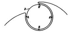
도3a는 4헤드를 채용한 헤드드럼 구조도.3A is a head drum structure diagram employing four heads.
도3b는 비디오테이프 기록패턴도.Fig. 3B is a video tape recording pattern diagram.
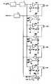
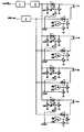
제4도는 본 발명 동시녹화·재생장치의 구성도.4 is a block diagram of a simultaneous recording and reproducing apparatus of the present invention.
제5도는 제4도의 신호타이밍도.5 is a signal timing diagram of FIG.
제6도는 본 발명에서 동시재생용 스위칭제어신호발생부의 상세도.6 is a detailed view of a switching control signal generator for simultaneous reproduction in the present invention.
* 도면의 주요 부분에 대한 부호의 설명* Explanation of symbols for the main parts of the drawings
1,3 : Y/C신호처리회로 2 : Y/C혼합회로1,3: Y / C signal processing circuit 2: Y / C mixed circuit
RECI-REC4 : 기록증폭기 PRE1-PRE4 : 전치증폭기RECI-REC4: Record Amplifier PRE1-PRE4: Pre-Amplifier
O1-O4 : 오아게이트 D1-D8 : 다이오드O1-O4: Oagate D1-D8: Diode
S3,S7,S11,S15 : 재생절환용 스위치S3, S7, S11, S15: Regeneration Switch
S4,S8,S12,S16 : 동시재생절환용 스위치S4, S8, S12, S16: Switch for simultaneous playback
S1,S2,S5,S6,S9,S10,S14,S14 : 기록절환용 스위치S1, S2, S5, S6, S9, S10, S14, S14: Record Switch
본 발명은 4헤드로 비디오신호를 기록하고 재생하는 브이씨알에 관한 것으로, 특히 헤드드럼상의 4헤드를 스위칭하여 비디오신호를 기록하면서 동시에 재생하여 봄으로써 정상적인 기록이 이루어지고 있는지를 확인할 수 있도록 하는 동시녹화·재생장치에 관한 것이다.The present invention relates to a V-Cal for recording and reproducing video signals with four heads, and in particular, by switching four heads on a head drum to simultaneously record and play a video signal, thereby confirming that normal recording is being made. It relates to a recording / playback apparatus.
제1도는 종래 녹화·재생장치의 구성을 보인 것으로, 외부로부터 입력되는 비디오신호는 Y/C신호처리회로(1)와 Y/C혼합회로(2) 및 기록절환용스위치(S1,S4,S7,S10)의 일측단자를 통해 기록증폭기(RECI-REC4)에 입력되고, 이 기록증폭기(RECI-REC4)의 출력은 기록절환용 스위치(S2,S5,S8,S11)의 일측단자를 통해 헤드(CH1-CH4)에 공급되며, 이 헤드(CH1-CH4)에 의해 비디오테이프로부터 독취되는 비디오신호는 재생절환용 스위치(S3,S6,S9,S12)의 일측단자를 통해 전치증폭기(PRE1-PRE4)에 입력되고, 이 전치증폭기(PRE1-PRE4)의 출력은 Y/C신호처리회로(3)를 통해 외부로 출력되도록 구성되어 있다.1 shows a configuration of a conventional recording / reproducing apparatus, wherein video signals input from the outside are Y / C
이때, 상기 기록절환용 스위치(S1,S4,S7,S10)는 스위치제어신호(SW1-SW4)에 의해 온,오프되어 상기 기록증폭기(REC1-REC4)의 입력측을 접지시키거나 접지시키지 않도록 되어 있다.At this time, the recording switching switches S1, S4, S7, and S10 are turned on and off by the switch control signals SW1 to SW4 so as not to ground or ground the input side of the recording amplifiers REC1 to REC4. .
그리고, 상기 기록절환용 스위치(S2,S5,S8,S11)는 재생신호(PB)에 의해 온,오프되어 상기 기록증폭기(REC1-REC4)의 출력측을 접지시키거나 접지시키지 않도록 되어 있다.The recording switching switches S2, S5, S8, and S11 are turned on and off by the reproduction signal PB so as not to ground or ground the output side of the recording amplifiers REC1 to REC4.
마지막으로, 상기 재생절환용 스위치(S3,S6,S9,S12)는 기록신호(REC)와 스위칭제어신호(SW1-SW4)를 오아논리연산하는 오아게이트(O1-O4)의 출력에 의해 전치증폭기(PRE1-PRE4)의 입력측을 접지시키거나 접지시키지 않도록 되어 있다.Finally, the regeneration switching switches S3, S6, S9, and S12 are preamplifiers based on the outputs of the oragates O1-O4 that perform an orlogical operation on the recording signal REC and the switching control signals SW1-SW4. The input side of (PRE1-PRE4) is grounded or not grounded.
이러한 종래 녹화·재생장치의 작용을 비디오테이프에 대한 비디오신호의 기록시와 재생시로 나누어 설명한다.The operation of the conventional recording and reproducing apparatus will be described by dividing the video signal into the video tape during recording and reproduction.
먼저, 비디오신호의 기록시이다.First, at the time of recording a video signal.
비디오테이프에의 비디오신호 기록시에는, 전치증폭기(PRE1-PRE4)의 입력측에 연결되어 있는 재생절환용 스위치(S3,S6,S9,S12)를 온,오프시키도록 되어 있는 오아게이트(O1-O4)의 일측단자에 '하이'의 기록신호(REC)가 입력되고(기록시이므로), 기록증폭기(REC1-REC4)의 출력측에 연결되어 있는 기록절환용 스위치(S2,S5,S8,S11)에 '로우'의 재생신호(PB)가 입력된다.When recording a video signal on the video tape, the OA gate O1-O4 is configured to turn on and off the regeneration switching switches S3, S6, S9, and S12 connected to the inputs of the preamplifiers PRE1 to PRE4. The recording signal REC of 'high' is input to one terminal of the terminal (because it is a proxy), and is connected to the recording switching switches S2, S5, S8, and S11 connected to the output side of the recording amplifiers REC1-REC4. A reproduction signal PB of 'low' is input.
이에 따라, 기록절환용 스위치(S2,S5,S8,S11)가 상기 로우의 재생신호(PB)에 의해 오프되어 기록증폭기(REC1-REC4)의 출력측이 접지되지 않으므로 그 기록증폭기(REC1-REC4)에서 출력되는 비디오신호가 헤드(CH1-CH4)에 공급된다.Accordingly, the recording switching switches S2, S5, S8 and S11 are turned off by the low reproduction signal PB so that the output side of the recording amplifiers REC1-REC4 is not grounded, so that the recording amplifiers REC1-REC4 are not grounded. The video signal output from is supplied to the heads CH1-CH4.
그리고, 재생절환용 스위치(S3,S6,S9,S12)를 온,오프시키도록 되어 있는 상기 오아게이트(O1-O4)는 일측단자에 하이의 기록신호(REC)가 입력되어 있으므로 다른 일측단자에 입력되는 스위치제어신호(SW1-SW4)에 따라, 즉 스위칭제어신호(SW1-SW4)가 '하이'일 때는 오아논리연산에 의해 로우신호를 출력하고 기록절환용 스위치(S3,S6,S9,S12)를 오프시키고 스위칭제어신호(SW1-SW4)가 '로우'일 때에는 기록신호(REC)에 의한 하이신호를 출력하여 그 기록절환용 스위치(S3,S6,S9,S12)를 온시킨다.The OA gates O1-O4 which are configured to turn on and off the regeneration switching switches S3, S6, S9, and S12 have high recording signals REC input to one terminal, and therefore to the other terminal. According to the input switch control signals SW1-SW4, that is, when the switching control signals SW1-SW4 are 'high', a low signal is output by the aorical operation and the write switching switches S3, S6, S9, and S12 are used. ) Is turned off, and when the switching control signals SW1-SW4 are 'low', a high signal generated by the recording signal REC is output to turn on the recording switching switches S3, S6, S9, and S12.
또 기록증폭기(REC1-REC4)의 입력측에 일측단자가 연결되어 있는 기록절환용 스위치(S1,S4,S7,S10)도 상기 스위치제어신호(SW1-SW4)에 따라 오프되어 기록을 위해 Y/C혼합회로(2)로부터 출력되는 비디오신호를 기록증폭기(REC1-REC4)에 입력시킨다.In addition, the recording switching switches S1, S4, S7, and S10 having one terminal connected to the input side of the recording amplifiers REC1 to REC4 are turned off in accordance with the switch control signals SW1 to SW4 so that Y / C can be used for recording. The video signal output from the
이에 따라, 외부로부터 입력되는 비디오신호가 헤드(CH1-CH4)에 의해 비디오테이프에 기록된다.Accordingly, the video signal input from the outside is recorded on the video tape by the heads CH1-CH4.
제2a도는 기록시 상기 스위칭제어신호(SW1-SW4)에 대한 타이밍도이다.2A is a timing diagram for the switching control signals SW1-SW4 at the time of writing.
다음은, 비디오테이프로부터의 비디오신호 재생시이다.The following is a video signal reproduction from the video tape.
비디오테이프에 기록되어 있는 비디오신호의 재생시에는, 재생절환용 스위치(S3,S6,S9,S12)를 온,오프시키도록 되어 있는 오아게이트(O1-O4)의 일측단자에 '로우'의 기록신호(REC)가 입력되고(재생시이므로), 기록절환용 스위치(S2,S5,S8,S11)에 '하이'의 재생신호(PB)가 입력된다.When reproducing the video signal recorded on the video tape, a recording signal of 'low' at one terminal of the oragate (O1-O4) which is to turn on / off the switching switch (S3, S6, S9, S12). (REC) is input (because at the time of reproduction), and the 'high' reproduction signal PB is input to the recording switching switches S2, S5, S8, and S11.
이에 따라, 그 기록절환용 스위치(S2,S5,S8,S11)가 온되어 기록증폭기(REC1-REC4)의 출력측이 접지되어시 기록증폭기(REC1-REC4)에서 출력되는 비디오신호는 헤드(CH1-CH4)에 공급되지 않는다.Accordingly, when the recording switching switches S2, S5, S8, and S11 are turned on and the output side of the recording amplifier REC1-REC4 is grounded, the video signal output from the recording amplifier REC1-REC4 is connected to the head CH1-. CH4) is not supplied.
상기 오아게이트(O1-O4)는, 앞서 언급한 바와 같이, 일측단자에 로우의 신호기록(REC)가 입력되므로 다른 일측단자에 입력되는 스위치제어신호(SW1-SW4)에 따라, 즉 스위칭제어신호(SW1-SW4)가 '하이'일 때는 오아논리 연산에 의해 하이신호를 출력하여 재생절환용 스위치(S3,S6,S9,S12)를 온시켜서 전치증폭기(PRE1-PRE4)의 입력측을 접지시키고, 스위칭제어신호(SW1-SW4)가 '로우'일 때에는 그 재생절환용 스위치(S3,S6,S9,S12)를 오프시켜서 헤드(CH1-CH4)에 의해 독취된 비디오신호가 상기 전치증폭기(PRE1-PRE4)에 입력되도록 하여 비디오신호가 재생되도록 한다.As described above, the oA gates O1-O4 are supplied with the signal recording REC of one row at one terminal thereof, and according to the switch control signals SW1-SW4 input at the other one terminal, that is, the switching control signal. When (SW1-SW4) is 'high', a high signal is output by an onalogical operation to turn on the regeneration switching switches (S3, S6, S9, S12) and ground the input side of the preamplifier (PRE1-PRE4). When the switching control signal SW1-SW4 is 'low', the video signal read out by the head CH1-CH4 is turned off by turning off the reproduction switching switches S3, S6, S9, and S12. Video signal is reproduced.
제2b도는 재생시 상기 스위칭제어신호(SW1-SW4)의 타이밍도이다.2B is a timing diagram of the switching control signals SW1-SW4 during reproduction.
이러한 종래의 4헤드를 채용한 헤드드럼을 사용한 브이씨알에서는, 기록시에 실제로 비디오신호가 비디오 테이프에 잘 기록되는지의 여부는 알 수가 없으므로 기록 후에 재생시 화면에 이상이 있는 경우 귀중한 장면을 잃게 되는 문제점이 있다.In VR, which uses the head drum adopting the conventional four heads, it is impossible to know whether or not the video signal is actually recorded on the video tape during recording. Therefore, if there is an abnormality on the screen during recording, valuable scenes are lost. There is a problem.
본 발명은, 이러한 종래의 문제점을 감안하여 창안된 것이며, 비디오신호가 잘 기록되고 있는지 확인할 수 있도록 비디오신호를 기록과 동시에 재생시킬 수 있는 동시녹화·재생장치를 제공하는 것을 목적으로 한다.The present invention has been devised in view of such a conventional problem, and an object of the present invention is to provide a simultaneous recording and reproducing apparatus capable of simultaneously reproducing a video signal so as to confirm whether the video signal is well recorded.
상기목적에 따른 본 발명은 동시녹화·재생장치는 Y/C신호처리회로와 Y/C혼합회로를 통해 입력되는 비디오신호를 증폭하여 4헤드에 공급하는 4개의 기록증폭기와 ; 외부로부터 스위칭제어신호에 따라 온,오프되어 상기 기록증촉기의 입력측을 접지시키거나 접지시키지 않는 4개의 기록제어용 스위치와 ; 비디오테이프로부터 상기 헤드에 의해 독취되는 비디오신호를 증폭하여 외부로 출력하는 4개의 전치증폭기와 ; 외부로부터 입력되는 기록용 스위칭제어신호를 2/3반주기만큼 지연스켜서 동시재생용 스위칭제어신호를 발생하는 동시재생용 스위칭제어신호발생부와 ; 상기 동시재생용 스위칭제어신호와 외부로부터 재생신호를 다이오드를 통해 입력받아서 상기 기록증폭기의 출력측을접지시키거나 접지시키지 않는 4개의 기록절환용 스위치와 ; 기록시 상기 동시재생용 스위칭제어신호에 따라 온,오프되는 4개의 동새재생절환용 스위치와 ; 상기 동시재생절환용 스위치의 온,오프에 따라 온,오프되어 상기 전치증폭기의 출력측을 접지시키지 않거나 접지시키는 4개의 재생절환용 스위치로 구성된다.According to the present invention, a simultaneous recording and reproducing apparatus includes: four recording amplifiers for amplifying a video signal input through a Y / C signal processing circuit and a Y / C mixing circuit and supplying the same to four heads; Four recording control switches which are turned on or off in accordance with a switching control signal from the outside to ground or not ground the input side of the recording amplifier; Four preamplifiers for amplifying the video signal read by the head from the video tape and outputting the amplified video signal to the outside; A simultaneous reproducing switching control signal generation section for delaying the recording switching control signal input from the outside by 2/3 half periods to generate a simultaneous reproducing switching control signal; Four recording switching switches for receiving the simultaneous reproducing switching control signal and a reproducing signal from the outside and not grounding or grounding the output side of the recording amplifier; Four identical reproduction switching switches which are turned on and off in response to the simultaneous reproduction switching control signal during recording; It consists of four regenerative switching switches which are turned on or off according to the simultaneous regenerative switching switch on and off so as not to ground or ground the output side of the preamplifier.
이와 같이 구성된 본 발명 동시녹화·재생장치에 대하여 하나의 바람직한 실시예를 나타낸 제3도 내지 제6도를 참조하여 본 발명의 작용 및 효과를 상세히 설명한다. 단, 종래와 동일한 부분에 대한 상세한 설명은 생략한다.The operation and effects of the present invention will be described in detail with reference to FIGS. 3 to 6 showing one preferred embodiment of the present invention simultaneous recording and reproducing apparatus. However, detailed description of the same parts as in the prior art is omitted.
본 바람직한 실시예에 따른 동시녹화·재생장치는, 제4도에 나타낸 바와 같이, Y/C신호처리회로(1)를 통한 Y/C혼합회로(2)에 기록증폭기(REC1-R와 헤드(CH1-CH4)가 차례로 연결되고, 이 헤드(CH1-CH4) 에 전치증폭기(PRE1-PRE4)와 Y/C신호처리회로(3)가 차례로 연결되며, 상기 기록증폭기(REC1-REC4)의 입력측에 기록절환용 스위치(S1,S5,S9,S13)가 연결되고, 상기 기록증폭기(REC1-REC4)의 출력측에 기록절환용 스위치(S2,S6,S10,S14)가 연결되며, 이 기록절환용 스위치(S2,S6,S10,S14)에 다이오드(D1-D8)가 연결되고, 상기 전치증폭기(PRE1-PRE4)의 입력측에 재생절환용 스위치(S3,S7,S11,S15)가 연결되며, 이 재생절환용 스위치(S3,S7,S11,S15)에 오아게이트(O1-O4)와 동시재생절환용 스위치(S4,S8,S12,S16)가 공통연결되어 구성된다.In the simultaneous recording and reproducing apparatus according to the present embodiment, as shown in FIG. 4, the recording amplifiers REC1-R and the heads are provided in the Y /
제3a도는 본 발명에 따른 4헤드 헤드드럼의 구조를 보인 것으로, 기존의 헤드드럼(D)에 4헤드(A, B, A', B')를 취하고, A헤드와 A'헤드, 또 B헤드와 B'헤드간에는 서로 방위가 180o를 유지하도록 되어 있다.Figure 3a shows the structure of a four-head head drum according to the present invention, taking four heads (A, B, A ', B') to the existing head drum (D), head A, A 'head, B The head and the B 'head are arranged so as to maintain a 180° orientation.
이에 따라, A헤드에 의해 기록되는 비디오신호는 180o의 위상차로 따라오는 A'헤드에 의해 재생되고, B헤드에 의해 기록되는 비디오신호는 역시 180o의 위상차로 따라오는 B'헤드에 의해 재생되며, A'헤드에 의해 기록되는 비디오신호는 180o의 위상차로 따라오는 A헤드에 의해 재생되고, B'헤드에 의해 기록되는 비디오신호는 180o의 위상차로 따라오는 B헤드에 의해 재생되면서, 기록과 재생을 동시에 할 수 있는 구조를 가지고 있다.Accordingly, the video signal recorded by the A head, is reproduced by the head, B followed by a phase difference between the video signal is also 180o to be recorded by the B head, A followed by a 180o phase difference reproduction by the head The video signal recorded by the head A 'is reproduced by the head A which follows a phase difference of 180o , and the video signal recorded by the head B' is reproduced by the head B which follows a phase difference of 180o , It has a structure that can record and play simultaneously.
제3b도는 본 발명 동시녹화·재생장치에서의 비디오테이프 기록패턴도를 보인 것으로, A헤드가 기록한 비디오신호중 A'헤드로 재생되는 트랙상의 부분은 빗금친 부분에 해당한다.3B shows a videotape recording pattern diagram in the simultaneous recording and reproducing apparatus of the present invention, in which the portion on the track reproduced by the head A 'of the video signal recorded by the head A corresponds to the hatched portion.
제6도는 동시재생용 스위칭제어신호를 발생하는 공시재생용 스위칭제어신호발생부를 보인 것으로, 카운터(CNI)와 디플립플롭(D-F/F)과 카운터(CN2)로 구성되어 있다.FIG. 6 shows the announcement reproduction switching control signal generation unit for generating the simultaneous reproduction switching control signal, which is composed of a counter CNI, a de-flip flop D-F / F, and a counter CN2.
이러한 구성에서, 카운터(CN1)는 제5도에 'SW30'으로 나타낸 바와 같은 기록용 스위칭제어신호를 일측입력단자를 통해 입력받고 그 기록용 스위칭제어신호(SW30)의 라이징에지에서 리세트되면서 다른 일측 입력단자를 통해 입력되는 클럭신호를 계수하기 시작한다.In this configuration, the counter CN1 receives a recording switching control signal as shown by SW30 in FIG. 5 through one input terminal and resets it at the rising edge of the recording switching control signal SW30. It starts counting the clock signal inputted through one input terminal.
이 계수로, 상기 기록용 스위칭 제어신호(SW30)의 2/3반주기에 해당하는 시간에 도달하면 '하이'로 상승하는 신호를 래치로서 작용하는 디플립플롭(D-F/F)을 통해 외부로 출력한다.With this coefficient, when the time corresponding to the 2/3 half period of the recording switching control signal SW30 is reached, the signal rising to 'high' is output to the outside through the deflip-flop (DF / F) serving as a latch. do.
그러면, 카운터(CN2)는 입력되는 클럭신호를 계수하면서 상기 기록용 스위칭제어신호(SW30)의 2/3반주기에 해당하는 시간이 지나서 3/3반주기, 즉 반주기에 해당하는 시간에 도달하면 하이신호를 출력하여 상기 디플립플롭(D-F/F)을 클리어시킨다.Then, the counter CN2 counts the input clock signal, and when the time corresponding to 2/3 half cycle of the recording switching control signal SW30 reaches 3/3 half cycle, that is, the time corresponding to half cycle, the high signal is received. Output to clear the flip-flop (DF / F).
이에 따라, 디플립플롭(D-F/F)의 출력단자(Q)에서는 카운터(CN1)에 입력되는 상기 기록용 스위칭제어신호(SW30)가 2/3반주기만큼 지연되어 출력되는 결과가 되며, 이처럼 2/3반주기만큼 지연되어 출력되는 기록용 스위칭제어신호(SW30)가 제5도에 'SW30'으로 나타낸 '동시재생용 스위칭제어신호'이다.Accordingly, in the output terminal Q of the flip-flop DF / F, the recording switching control signal SW30 input to the counter CN1 is delayed by 2/3 half cycles, and thus output is performed. The recording switching control signal SW30, which is output by being delayed by a half cycle, is the 'simultaneous reproduction switching control signal' shown in FIG. 5 as 'SW30'.
이 동시재생용 스위칭제어신호(SW30)는 제4도에 [SW1'-SW4']로 나타내어져 있으며, 이러한 동시재생용 스위칭제어신호(SW1'-SW4')가 기록시에 제4도의 다이오드(D2,D4,D6,D8)와 동시재생절환용 스위ㅊ(S4,S8,S12,S16)에 입력되면 비디오테이프에 대한 비디오신호의 기록과 재생이 동시에 가능해진다.This simultaneous reproducing switching control signal SW30 is shown in FIG. 4 as [SW1'-SW4 '], and this simultaneous reproducing switching control signal SW1'-SW4' is shown in FIG. When input to D2, D4, D6, and D8 and simultaneous playback switching switches S4, S8, S12, and S16, recording and reproduction of video signals on videotape can be performed simultaneously.
이를 상세히 설명한다.This will be described in detail.
비디오테이프에서 비디오신호 기록시에 기록신호(REC)가 '하이'인 상태에서, 제6도의 동시재생용 스위칭제어신호발생부에서 발생되는 '하이'의 동시재생용 스위칭제어신호(SW1')가 다이오드(D2)를 통해 기록절환용 스위치(S2)에 입력되고 바로 동시재생절환용 스위치(S4)에 입력되면, 그 기록절환용 스위치(S2)와 동시재생절환용 스위치(4)는 온된다.When the recording signal REC is 'high' when the video signal is recorded on the video tape, the 'high' simultaneous playback switching control signal SW1 generated by the simultaneous playback switching control signal generator of FIG. When it is input to the recording switching switch S2 via the diode D2 and immediately to the simultaneous reproduction switching switch S4, the recording switching switch S2 and the simultaneous
특히, 상기 동시재생절환용 스위치(S4)의 온으로, 이 동시재생절환용 스위치(S4)에 따라 온,오프되도록 되어 있는 재생절환용 스위치(S3)는 반대로 오프된다.In particular, when the simultaneous regeneration switching switch S4 is turned on, the regeneration switching switch S3 which is to be turned on and off in accordance with the simultaneous regeneration switching switch S4 is turned off.
이와 같이, 기록증폭기(REC1)의 출력측에 연결되어 있는 상기 기록절환용 스위치(S2)가 온되고, 전치증폭기(PRE1)의 입력측에 연결되어 있는 상기 재생절환용 스위치(S3)가 오프되면, 헤드(CH3)(가령, 제3도의 A'헤드)에 의해 비디오테이프에 기록된 비디오신호가 180o의 위상차로 따라오는 헤드(CH1)(가령, 제3도의 A헤드)에 의해 독취되어 전치증폭기(PRE1)에서 증폭되고 이어서 Y/C신호처리회로(3)에 입력됨으로써 비디오테이프에 있는비디오신호의 재생이 기록중에도 이루어진다.As described above, when the recording switching switch S2 connected to the output side of the recording amplifier REC1 is turned on and the reproduction switching switch S3 connected to the input side of the preamplifier PRE1 is turned off, the head is turned off. (CH3) (e.g., third degree a 'head) is a video signal recorded on the video tape by the read by the head (CH1) (e.g., third degree a head) followed by a phase difference of 180o preamplifier ( By amplifying in PRE1 and then inputting to the Y / C
마찬가지로, 다른 동시재생용 스위칭제어신호(SW2'-SW4')에 의해, 기록증폭기(REC2-REC5)의 출력측에 연결되어 있는 기록절환용 스위치(S6,S10,S14)가 온되고, 전치증폭기(PRE2-PRE4)의 입력측에 연결되어 있는 재생절환용 스위치(S7,S11,S15)가 오프되면, 헤드(CH2-CH4)에 의해 독취된 비디오신호가 전치증폭기(PRE2-PRE4)에서 증폭되고 이어서 Y/C신호처리회로(3)에 입력됨으로써 비디오테이프에 있는 비디오신호의 재생이 기록중에서도 이루어진다.Similarly, by the other simultaneous reproducing switching control signals SW2'-SW4 ', the recording switching switches S6, S10, S14 connected to the output side of the recording amplifier REC2-REC5 are turned on, and the preamplifier ( When the playback switching switches S7, S11, S15 connected to the input side of PRE2-PRE4 are turned off, the video signal read by the head CH2-CH4 is amplified by the preamplifier PRE2-PRE4 and then Y Input to the / C
이상에서 상세히 설명한 바와 같이, 본 발명 동시녹화·재생장치는, 기록시에 기록되는 비디오신호를 곧바로 동시에 재생하여 볼 수 있으므로 기록이 잘되고 있는지를 기록중에 확인할수 있게 되어 오기록을 방지할 수 있는 효과를 갖는다.As described in detail above, the present invention simultaneously records and reproduces the video signal recorded at the time of recording, and can be immediately reproduced simultaneously, so that it is possible to check whether the recording is well performed during recording, thereby preventing the false recording. Has
Claims (1)
Translated fromKoreanPriority Applications (1)
| Application Number | Priority Date | Filing Date | Title |
|---|---|---|---|
| KR1019890014911AKR0121171B1 (en) | 1989-10-17 | 1989-10-17 | Synchronous recording and reproducing apparatus |
Applications Claiming Priority (1)
| Application Number | Priority Date | Filing Date | Title |
|---|---|---|---|
| KR1019890014911AKR0121171B1 (en) | 1989-10-17 | 1989-10-17 | Synchronous recording and reproducing apparatus |
Publications (2)
| Publication Number | Publication Date |
|---|---|
| KR910008665A KR910008665A (en) | 1991-05-31 |
| KR0121171B1true KR0121171B1 (en) | 1997-11-20 |
Family
ID=19290769
Family Applications (1)
| Application Number | Title | Priority Date | Filing Date |
|---|---|---|---|
| KR1019890014911AExpired - Fee RelatedKR0121171B1 (en) | 1989-10-17 | 1989-10-17 | Synchronous recording and reproducing apparatus |
Country Status (1)
| Country | Link |
|---|---|
| KR (1) | KR0121171B1 (en) |
Cited By (1)
| Publication number | Priority date | Publication date | Assignee | Title |
|---|---|---|---|---|
| KR100677080B1 (en)* | 2000-01-14 | 2007-02-01 | 삼성전자주식회사 | TS signal switching device for digital television |
- 1989
- 1989-10-17KRKR1019890014911Apatent/KR0121171B1/ennot_activeExpired - Fee Related
Cited By (1)
| Publication number | Priority date | Publication date | Assignee | Title |
|---|---|---|---|---|
| KR100677080B1 (en)* | 2000-01-14 | 2007-02-01 | 삼성전자주식회사 | TS signal switching device for digital television |
Also Published As
| Publication number | Publication date |
|---|---|
| KR910008665A (en) | 1991-05-31 |
Similar Documents
| Publication | Publication Date | Title |
|---|---|---|
| US4775901A (en) | Apparatus and method for preventing unauthorized dubbing of a recorded signal | |
| CA1240794A (en) | Tape speed determining apparatus for video signal reproducing apparatus | |
| US4723176A (en) | Video tape recorders | |
| KR0121171B1 (en) | Synchronous recording and reproducing apparatus | |
| KR900003309B1 (en) | The method of herical type magnetic recording | |
| JPS601654A (en) | Recording device | |
| US5057948A (en) | Recording of digital signals on d.c.-erased magnetic tape | |
| KR920005332B1 (en) | Megnetic recording and play back apparatus | |
| JPS553243A (en) | Recorder/reproducer for still picture | |
| KR900002631Y1 (en) | Recording status checking circuit of video cassette recorder | |
| JP2777424B2 (en) | Magnetic recording / reproducing device | |
| KR0132494B1 (en) | Magnetic recording and playback equipment | |
| JPH0345356Y2 (en) | ||
| JPS645178A (en) | Magnetic video recording and reproducing device | |
| KR870001011B1 (en) | Image Head Phase Detection Device of Video Tape Recorder | |
| JPH0528598Y2 (en) | ||
| KR900001148B1 (en) | P.c.m. audio signal recording & reproducing apparatus of video cassette recorder | |
| JP2678307B2 (en) | Tracking detection device in magnetic recording / reproducing device | |
| JPS60151863A (en) | magnetic recording and reproducing device | |
| JPS63231752A (en) | tracking device | |
| JPS6359081A (en) | Signal reproducing device | |
| JPS62140260A (en) | Searching device for vtr | |
| JPS63242078A (en) | Long-term audio recording device for time-lapse video tape recorder | |
| JPS6396702A (en) | Video tape recorder audio dubbing method | |
| JPS61260401A (en) | magnetic recording and reproducing device |
Legal Events
| Date | Code | Title | Description |
|---|---|---|---|
| PA0109 | Patent application | St.27 status event code:A-0-1-A10-A12-nap-PA0109 | |
| R17-X000 | Change to representative recorded | St.27 status event code:A-3-3-R10-R17-oth-X000 | |
| PG1501 | Laying open of application | St.27 status event code:A-1-1-Q10-Q12-nap-PG1501 | |
| A201 | Request for examination | ||
| P11-X000 | Amendment of application requested | St.27 status event code:A-2-2-P10-P11-nap-X000 | |
| P13-X000 | Application amended | St.27 status event code:A-2-2-P10-P13-nap-X000 | |
| PA0201 | Request for examination | St.27 status event code:A-1-2-D10-D11-exm-PA0201 | |
| R17-X000 | Change to representative recorded | St.27 status event code:A-3-3-R10-R17-oth-X000 | |
| E701 | Decision to grant or registration of patent right | ||
| PE0701 | Decision of registration | St.27 status event code:A-1-2-D10-D22-exm-PE0701 | |
| GRNT | Written decision to grant | ||
| PR0701 | Registration of establishment | St.27 status event code:A-2-4-F10-F11-exm-PR0701 | |
| PR1002 | Payment of registration fee | St.27 status event code:A-2-2-U10-U11-oth-PR1002 Fee payment year number:1 | |
| PG1601 | Publication of registration | St.27 status event code:A-4-4-Q10-Q13-nap-PG1601 | |
| PN2301 | Change of applicant | St.27 status event code:A-5-5-R10-R13-asn-PN2301 St.27 status event code:A-5-5-R10-R11-asn-PN2301 | |
| PN2301 | Change of applicant | St.27 status event code:A-5-5-R10-R13-asn-PN2301 St.27 status event code:A-5-5-R10-R11-asn-PN2301 | |
| PR1001 | Payment of annual fee | St.27 status event code:A-4-4-U10-U11-oth-PR1001 Fee payment year number:4 | |
| PN2301 | Change of applicant | St.27 status event code:A-5-5-R10-R13-asn-PN2301 St.27 status event code:A-5-5-R10-R11-asn-PN2301 | |
| PR1001 | Payment of annual fee | St.27 status event code:A-4-4-U10-U11-oth-PR1001 Fee payment year number:5 | |
| FPAY | Annual fee payment | Payment date:20020726 Year of fee payment:6 | |
| PR1001 | Payment of annual fee | St.27 status event code:A-4-4-U10-U11-oth-PR1001 Fee payment year number:6 | |
| PN2301 | Change of applicant | St.27 status event code:A-5-5-R10-R11-asn-PN2301 | |
| PN2301 | Change of applicant | St.27 status event code:A-5-5-R10-R13-asn-PN2301 St.27 status event code:A-5-5-R10-R11-asn-PN2301 | |
| LAPS | Lapse due to unpaid annual fee | ||
| PC1903 | Unpaid annual fee | St.27 status event code:A-4-4-U10-U13-oth-PC1903 Not in force date:20030826 Payment event data comment text:Termination Category : DEFAULT_OF_REGISTRATION_FEE | |
| PC1903 | Unpaid annual fee | St.27 status event code:N-4-6-H10-H13-oth-PC1903 Ip right cessation event data comment text:Termination Category : DEFAULT_OF_REGISTRATION_FEE Not in force date:20030826 | |
| P22-X000 | Classification modified | St.27 status event code:A-4-4-P10-P22-nap-X000 |