JPWO2020235100A1 - Terminal device and temperature control system - Google Patents
Terminal device and temperature control systemDownload PDFInfo
- Publication number
- JPWO2020235100A1 JPWO2020235100A1JP2019557646AJP2019557646AJPWO2020235100A1JP WO2020235100 A1JPWO2020235100 A1JP WO2020235100A1JP 2019557646 AJP2019557646 AJP 2019557646AJP 2019557646 AJP2019557646 AJP 2019557646AJP WO2020235100 A1JPWO2020235100 A1JP WO2020235100A1
- Authority
- JP
- Japan
- Prior art keywords
- temperature
- display unit
- terminal device
- user
- information
- Prior art date
- Legal status (The legal status is an assumption and is not a legal conclusion. Google has not performed a legal analysis and makes no representation as to the accuracy of the status listed.)
- Pending
Links
Images


Classifications
- F—MECHANICAL ENGINEERING; LIGHTING; HEATING; WEAPONS; BLASTING
- F24—HEATING; RANGES; VENTILATING
- F24F—AIR-CONDITIONING; AIR-HUMIDIFICATION; VENTILATION; USE OF AIR CURRENTS FOR SCREENING
- F24F11/00—Control or safety arrangements
- F24F11/50—Control or safety arrangements characterised by user interfaces or communication
- F24F11/52—Indication arrangements, e.g. displays
- F24F11/523—Indication arrangements, e.g. displays for displaying temperature data
Landscapes
- Engineering & Computer Science (AREA)
- Human Computer Interaction (AREA)
- Chemical & Material Sciences (AREA)
- Combustion & Propulsion (AREA)
- Mechanical Engineering (AREA)
- General Engineering & Computer Science (AREA)
- Air Conditioning Control Device (AREA)
Abstract
Translated fromJapaneseDescription
Translated fromJapaneseこの発明は、端末装置および温度制御システムに関する。 The present invention relates to terminal devices and temperature control systems.
特許文献1には、人が所定の屋内空間からその他の屋内空間に移動した際におけるヒートショックの発生を抑制することができる建物の空調システムが開示されている。特許文献1の空調システムは、複数の居室のうち空気供給元として選択された居室から脱衣室に空気を供給させる。 Patent Document 1 discloses an air conditioning system for a building that can suppress the occurrence of heat shock when a person moves from a predetermined indoor space to another indoor space. The air conditioning system of Patent Document 1 supplies air to the undressing room from the room selected as the air supply source among the plurality of living rooms.
特許文献1の空調システムでは、浴室に向かう際の動線上の部屋について、使用者が温度情報を把握することはできない。また、空調システムの設定が煩雑となるおそれがある。 In the air conditioning system of Patent Document 1, the user cannot grasp the temperature information about the room on the flow line when going to the bathroom. In addition, the setting of the air conditioning system may become complicated.
本発明は上述の問題を解決するためになされたものであり、第1の目的は、間取りに含まれる複数の部屋の温度情報を使用者が容易に把握できる端末装置および温度制御システムを得ることである。
本発明の第2の目的は、入浴時の行動予定を容易に入力できる端末装置および温度制御システムを得ることである。The present invention has been made to solve the above-mentioned problems, and a first object of the present invention is to obtain a terminal device and a temperature control system in which a user can easily grasp temperature information of a plurality of rooms included in a floor plan. Is.
A second object of the present invention is to obtain a terminal device and a temperature control system that can easily input an action schedule at the time of bathing.
本願の第1の発明に係る端末装置は、空間の間取りを検出する検出部と、表示部と、該検出部が検出した情報から該間取りの画像を作成し、該間取りに含まれる複数の部屋にそれぞれ対応する複数の温度情報を取得し、該画像と該複数の温度情報とを対応させて該表示部に表示させる制御部と、を備える。 The terminal device according to the first invention of the present application creates an image of the floor plan from a detection unit for detecting the floor plan of the space, a display unit, and information detected by the detection unit, and a plurality of rooms included in the floor plan. It is provided with a control unit that acquires a plurality of temperature information corresponding to each of the above and displays the image and the plurality of temperature information on the display unit in correspondence with each other.
本願の第2の発明に係る端末装置は、表示部と、空間の間取りの画像を該表示部に表示させる制御部と、を備え、該表示部には、タップ操作または該画像をなぞることで、使用者が浴室に向かう動線が入力される。 The terminal device according to the second invention of the present application includes a display unit and a control unit for displaying an image of the floor plan of the space on the display unit, and the display unit can be tapped or traced with the image. , The flow line for the user to the bathroom is input.
本願の第1の発明に係る端末装置では、間取りと、間取りに含まれる複数の部屋の温度情報とが対応した状態で表示される。従って、間取りに含まれる複数の部屋の温度情報を使用者が容易に把握できる。
本願の第2の発明に係る端末装置では、タップ操作または間取りの画像をなぞることで、使用者が浴室に向かう動線が入力される。従って、入浴時の行動予定を容易に入力できる。In the terminal device according to the first invention of the present application, the floor plan and the temperature information of a plurality of rooms included in the floor plan are displayed in a corresponding state. Therefore, the user can easily grasp the temperature information of a plurality of rooms included in the floor plan.
In the terminal device according to the second invention of the present application, a flow line toward the bathroom is input by the user by tracing an image of a tap operation or a floor plan. Therefore, it is possible to easily input the action schedule at the time of bathing.
本発明の実施の形態に係る端末装置および温度制御システムについて図面を参照して説明する。同じ又は対応する構成要素には同じ符号を付し、説明の繰り返しを省略する場合がある。 The terminal device and the temperature control system according to the embodiment of the present invention will be described with reference to the drawings. The same or corresponding components may be designated by the same reference numerals and the description may be omitted.
実施の形態1.
図1は、実施の形態1に係る温度制御システム100の構成を説明する図である。温度制御システム100は、端末装置20と制御装置10を備える。端末装置20は、例えばスマートフォンまたはタブレットである。制御装置10は建物に設けられた機器を連携させて制御する。制御装置10は、PCまたはHEMS(Home Energy Management System)における管理装置であっても良い。Embodiment 1.
FIG. 1 is a diagram for explaining the configuration of the
温度制御システム100は、温度調節部12、送風部14および給湯機16を備える。温度調節部12は例えばエアコン、ヒーターまたは床暖房である。温度調節部12は、居室に設けられるものに限らず、浴室暖房、浴室乾燥機、脱衣室暖房を含んでも良い。送風部14は、例えば換気扇、扇風機または送風機である。送風部14は、例えばクローゼット、トイレ、階段室、廊下、キッチン、玄関等に設けられる。送風部14は居室に設けられても良い。給湯機16は浴室に設けられる。給湯機16は浴槽への湯張りを行う。 The
温度制御システム100は、複数の温度センサ30を備える。複数の温度センサ30は、建物に含まれる複数の部屋にそれぞれ設けられる。温度センサ30は例えばエアコンに設けられる。また、温度センサ30は送風部14に設けられても良い。制御装置10は、複数の温度センサ30から、建物の複数の部屋にそれぞれ対応する複数の温度情報を取得する。制御装置10は、複数の温度情報を端末装置20に送信する。 The
温度制御システム100は、複数の画像センサ32を備える。制御装置10には、予め複数の使用者の顔が登録されている。制御装置10は、画像センサ32が検出した情報から、浴室に向かっている使用者を判別する。これに限らず、浴室に向かっている使用者を判別できれば、他のセンサが用いられても良い。例えば、制御装置10には予め複数の使用者の行動パタンが登録され、行動パタンセンサが検出した情報から浴室に向かっている使用者を判別しても良い。 The
制御装置10は、端末装置20から受信した情報と、温度センサ30および画像センサ32が検出した情報に基づき、温度調節部12、送風部14および給湯機16を制御する。制御装置10と各機器は、無線または有線通信により接続されている。 The
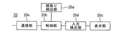
図2は、実施の形態1に係る端末装置20の機能ブロック図である。端末装置20は、間取り検出部20a、制御部20b、表示部20c、入力検出部20dおよび通信部20eを有する。間取り検出部20aは、空間の間取りを検出する。 FIG. 2 is a functional block diagram of the
制御部20bは、間取り検出部20aが検出した情報から間取りの画像を作成する。また、制御部20bは、制御装置10から送信された複数の温度情報を、通信部20eを介して受信する。これにより、制御部20bは間取りに含まれる複数の部屋にそれぞれ対応する複数の温度情報を取得する。制御部20bは、作成した画像と複数の温度情報とを対応させて、表示部20cに表示させる。制御部20bは、複数の部屋を複数の温度情報に基づき色分けして、表示部20cに表示させる。 The
表示部20cには、タップ操作または間取りの画像をなぞることで、使用者の入浴時の行動予定が入力される。表示部20cには、間取りの画像が表示された状態で使用者の入浴時の行動予定が入力される。行動予定には、使用者が浴室に向かう動線が含まれる。なお、タップ操作には、タップ、ダブルタップ、ロングタップ、マルチタップが含まれる。 The action schedule of the user at the time of bathing is input to the
入力検出部20dは、表示部20cから入力された情報を検出し、制御部20bに送信する。入力検出部20dは、例えば使用者が表示部20cを触ることで生じた信号を、制御部20bで解析できる信号に変換する。 The
通信部20eは、温度センサ30が検出した情報を制御装置10から受信して、制御部20bに送信する。また、通信部20eは、表示部20cから入力された行動予定を制御部20bから受信し、制御装置10に送信する。これにより、制御装置10は、受信した行動予定に応じて、温度調節部12または送風部14を制御して空間の温度を制御する。 The
図3は、実施の形態1に係る端末装置20のハードウェア構成図である。間取り検出部20aは位置センサ24から構成される。これに限らず、間取り検出部20aは、間取りを検出できれば良く、画像センサまたはカメラであっても良い。表示部20cは、タッチパネル23から構成される。 FIG. 3 is a hardware configuration diagram of the
制御部20b、入力検出部20dおよび通信部20eの機能は、プロセッサ21により実現される。プロセッサ21は、専用のハードウェアであっても良い。また、プロセッサ21は、メモリ22に格納されるプログラムを実行するCPU(Central Processing Unit)であってもよい。CPUは中央処理装置、処理装置、演算装置、マイクロプロセッサ、マイクロコンピュータ、プロセッサ、DSPとも呼ばれる。 The functions of the
プロセッサ21が専用のハードウェアである場合、プロセッサ21は、例えば、単一回路、複合回路、プログラム化したプロセッサ、並列プログラム化したプロセッサであっても良い。また、プロセッサ21は、ASIC(Application Specific Integrated Circuit)またはFPGA(Field−Programmable Gate Array)であっても良い。さらに、プロセッサ21は、これらを組み合わせたものであっても良い。また、制御部20b、入力検出部20dおよび通信部20eの各部の機能それぞれを、別個のプロセッサ21で実現しても良い。また、各部の機能をまとめてプロセッサ21で実現してもよい。 When the
プロセッサ21がCPUの場合、制御部20b、入力検出部20dおよび通信部20eの機能は、ソフトウェア、ファームウェア、またはソフトウェアとファームウェアとの組み合わせにより実現される。ソフトウェアおよびファームウェアはプログラムとして記述され、メモリ22に格納される。プロセッサ21は、メモリ22に記憶されたプログラムを読み出して実行することにより、各部の機能を実現する。 When the
すなわちメモリ22には、間取り検出部20aが検出した情報から間取りの画像を作成するプログラムと、作成した画像と複数の温度情報とを対応させて表示部20cに表示させるプログラムとが格納される。また、メモリ22には、表示部20cから入力された情報を検出および変換するプログラムが格納される。さらに、メモリ22には、温度センサ30が検出した情報を制御装置10から受信するプログラムと、表示部20cから入力された行動予定を制御装置10に送信するプログラムが格納される。これらのプログラムは、制御部20b、入力検出部20dおよび通信部20eにおける手順または方法をコンピュータに実行させるものであるともいえる。 That is, the
ここで、メモリ22は、RAM、ROM、フラッシュメモリ、EPROM、EEPROM等の不揮発性または揮発性の半導体メモリ、磁気ディスク、フレキシブルディスク、光ディスク、コンパクトディスク、ミニディスク、DVD等であっても良い。RAMはRandom Access Memoryの略称である。ROMはRead Only Memoryの略称である。EPROMはErasable Programmable Read Only Memoryの略称である。EEPROMはElectrically Erasable Programmable Read−Only Memoryの略称である。 Here, the
なお、制御部20b、入力検出部20dおよび通信部20eの各機能について、一部を専用のハードウェアで実現し、一部をソフトウェアまたはファームウェアで実現するようにしてもよい。例えば、入力検出部20dおよび通信部20eについては専用のハードウェアとしてのプロセッサ21でその機能を実現しても良い。また、制御部20bについてはプロセッサ21がメモリ22に格納されたプログラムを読み出して実行することによって、その機能を実現することが可能である。 Some of the functions of the
このように、プロセッサ21は、ハードウェア、ソフトウェア、ファームウェア、またはこれらの組み合わせによって、上述の各機能を実現することができる。 In this way, the
次に、温度制御システム100の使用方法について説明する。図4は、端末装置20の動作を説明するフローチャートである。まず、ステップS1に示されるように、間取り検出部20aにより間取りを検出する。図5は、間取りの検出方法を説明する図である。使用者は、端末装置20を持って住まいの各部屋を回る。この際、使用者が建物内を歩き回ることで、端末装置20は位置センサ24により、各部屋の壁面、位置、方向を検出する。また、端末装置20は、各部屋の広さ、高さおよび部屋同士のつながりを検出する。この際、使用者の歩数に基づき、各部屋の位置、広さ等が検出されても良い。また、壁、窓および扉の位置、家具の配置が使用者により入力されても良い。 Next, how to use the
間取り検出部20aが画像センサまたはカメラである場合も、使用者が端末装置20を持って住まいの各部屋を回ることで、端末装置20は各部屋の壁面、位置、方向、広さ、高さおよび部屋同士のつながりを検出できる。また、端末装置20は、画像センサまたはカメラにより、壁、窓および扉の位置、家具の配置を検出できる。 Even when the floor
空間の認識には、位置情報または画像情報から間取りを認識するアプリが用いられる。間取りを認識するアプリは、端末装置20に予めインストールされている。 For space recognition, an application that recognizes the floor plan from position information or image information is used. The application that recognizes the floor plan is pre-installed in the
また、通信部20eは、使用者が各部屋を訪れた際に、その部屋に設けられた温度センサ30と通信する。図5に示されるように、リビングダイニング、和室、脱衣室および浴室にはエアコン等の温度調節部12が設けられる。温度調節部12には温度センサ30が設けられている。また、一般に、エアコンが設けられないことが多いクローゼット、トイレ、階段室、廊下、キッチンでは、換気扇等の送風部14に温度センサ30が設けられる。また、壁掛けの暖房機に温度センサ30が設けられていても良い。 Further, when the user visits each room, the
これにより、制御部20bは、複数の部屋と、複数の部屋にそれぞれ設けられた複数の温度センサ30との対応関係を記憶する。対応関係はメモリ22に記憶される。このように、制御部20bは、間取り検出部20aにより間取りを検出する際に、検出する部屋に設けられた温度センサ30の情報を取得することで、部屋と温度センサ30との対応関係を取得する。これにより、効率よく制御に必要な情報を取得できる。これに限らず、部屋と温度センサ30との対応関係は使用者が手動で入力しても良い。 As a result, the
次に、ステップS2に示されるように、間取りの画像を作成する。また、ステップS3に示されるように、制御部20bは作成した画像を表示部20cに表示させる。画像の作成および表示についても、間取りを認識するアプリで実施される。 Next, as shown in step S2, an image of the floor plan is created. Further, as shown in step S3, the
図6は、間取りの画像50を説明する図である。アプリは、間取り検出部20aからの情報に基づき認識した空間を3Dもしくは2D画像に変換して、表示部20cに表示する。画像50には、現在の使用者の位置が表示されても良い。 FIG. 6 is a diagram illustrating an
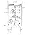
次に、ステップS4に示されるように、表示部20cから使用者の入浴時の行動予定が入力される。図7は、行動予定の入力方法を説明する図である。図7において端末装置20の表示部20cに、ステップS1〜3で作成した間取りの画像50が表示されている。なお、ここでは2階建ての建物の間取りが立体的に表示されている。これにより、使用者は画像50と実際の間取りの対応関係を容易に認識できる。 Next, as shown in step S4, the action schedule of the user at the time of bathing is input from the
表示部20cには、複数の使用者のリスト52が表示される。リスト52には、例えば建物に住む家族が含まれる。図7では、リスト52にお父さん、子ども1、子ども2、おじいちゃん、お母さんが含まれる例が示されている。設定操作を行う設定者は、何れの使用者の行動予定を入力するかをリスト52からタップ操作で選択する。 A
次に、設定者は、選択した使用者の入浴時の動線51を入力する。表示部20cには、画像50をなぞることで、使用者が浴室に向かう動線51が入力される。このとき、表示部20cには、設定者が画像50を指でなぞった軌跡が動線51として表示される。これに限らず、画像50上で移動順に部屋をタップ操作することで、動線51が入力されても良い。また、表示部20cの上端部には、現在選択されている使用者が表示される。これにより、設定者は何れの使用者についての情報を入力しているかを容易に認識できる。 Next, the setter inputs the
図8は、入浴開始時間の入力方法を説明する図である。表示部20cには、入浴開始時間のリスト53が表示される。設定者は、使用者の入浴開始時間をリスト53からタップ操作で選択する。これにより、表示部20cには、タップ操作で使用者の入浴開始時間が入力される。 FIG. 8 is a diagram illustrating a method of inputting a bathing start time. A
また、表示部20cには、使用者が浴室に向かう際の動線51上の各部屋での滞在時間が、タップ操作により入力される。また、表示部20cには、使用者の動線51上の各部屋の通過時間が、タップ操作により入力されても良い。 Further, the time spent in each room on the
図9は、温熱環境の入力方法を説明する図である。表示部20cには、温熱環境のリスト54が表示される。設定者は、使用者に適用する温熱環境をリスト54からタップ操作で選択する。これにより、表示部20cには、タップ操作で使用者に適用される温熱環境が入力される。 FIG. 9 is a diagram illustrating a method of inputting a thermal environment. A
ここで、温熱環境には、ヒートショックを抑制する環境、ヒートショックプロテインの生成を促す環境、熱中症を抑制する環境、消費電力を抑制する節電環境または快適性を実現する環境が含まれる。ヒートショックを抑制する環境が選択された場合、例えば動線51上における温度差を抑制する制御が制御装置10により実施される。ここで、制御装置10は各場所での使用者の快適性を維持しつつ、温度制御を行う。 Here, the thermal environment includes an environment that suppresses heat shock, an environment that promotes the production of heat shock protein, an environment that suppresses heat stroke, an environment that suppresses power consumption, or an environment that realizes comfort. When an environment for suppressing heat shock is selected, for example, control for suppressing the temperature difference on the
ヒートショックプロテインの生成を促す環境が選択された場合、例えば動線51上における温度を予め定められた規定値よりも高温に維持する制御が制御装置10により実施される。規定値は、ヒートショックプロテインの生成を促すことができる温度である。また、ヒートショックプロテインの生成を促す環境が選択された場合、高温による体調の悪化を防止するため、端末装置20は水分補給または休憩等を使用者に勧めても良い。この機能は、アプリ等で実施される。 When an environment that promotes the production of heat shock proteins is selected, for example, control for maintaining the temperature on the
熱中症を抑制する環境が選択された場合、例えば動線51上における温度を、予め定められた温度よりも低温に維持する制御が制御装置10により実施される。 When an environment for suppressing heat stroke is selected, for example, control for maintaining the temperature on the
節電環境が選択された場合、動線51上において消費電力の抑制が優先される。これにより、制御装置10は、動線51上の部屋に設けられた温度調節部12、送風部14、暖房機等を省エネ状態で動作させる。これにより、例えば冷房機能の設定温度が規定値よりも高く設定され、暖房機能の設定温度が規定値よりも低く設定される。また、エアコンの風量が規定値よりも低く設定されても良い。また、節電環境において、動線51上の部屋に設けられた温度調節部12、送風部14または暖房機が停止しても良い。 When the power saving environment is selected, the suppression of power consumption is prioritized on the
快適性を実現する環境では、動線51上において使用者の快適性を向上する制御が制御装置10により実施される。制御装置10は、使用者の皮膚の表面温度、年齢、代謝等から快適温度を検出する。制御装置10は、動線51上の温度が快適温度となるように制御を行う。皮膚の表面温度は、例えば温度センサ30により検出される。年齢、代謝等は初期設定時に端末装置20に入力される。快適温度は、少なくとも皮膚の表面温度に応じて決まる値であれば良い。快適温度は使用者の好みの温度であっても良い。 In an environment where comfort is realized, control for improving user comfort is performed by the
必要とされる温熱環境は、使用者により変わる。例えば、ヒートショック症状抑制の環境は、高齢者に必要とされることが多い。本実施の形態では、使用者に適した温熱環境を容易に選択できる。また、一般にヒートショック症状抑制の環境は寒い時期に必要とされることが多い。また、熱中症抑制の環境は、熱い時期に必要とされることが多い。本実施の形態では、気温に応じて適した温熱環境を容易に選択できる。また、図7で選択した使用者が子供または若年層である場合、自動で節電環境が選択されても良い。これにより、ヒートショック症状抑制の環境を高齢者のみに適用し、消費電力を抑制できる。 The required thermal environment varies from user to user. For example, an environment for suppressing heat shock symptoms is often needed by the elderly. In the present embodiment, a thermal environment suitable for the user can be easily selected. In general, an environment for suppressing heat shock symptoms is often required in cold weather. In addition, an environment for suppressing heat stroke is often required during hot weather. In the present embodiment, a suitable thermal environment can be easily selected according to the air temperature. Further, when the user selected in FIG. 7 is a child or a young person, a power saving environment may be automatically selected. As a result, the environment for suppressing heat shock symptoms can be applied only to the elderly, and power consumption can be suppressed.
以上から、表示部20cには、タップ操作で使用者を特定する情報が入力され、特定された使用者に対応する動線51、行動予定および温熱環境がタップ操作または画像50をなぞることで入力される。従って、容易に行動予定を入力できる。複数の使用者の全てについて、同様の設定が行われる。これにより表示部20cには、複数の使用者にそれぞれ対応する複数の動線51、行動予定および温熱環境が入力される。 From the above, information that identifies the user by tap operation is input to the
また、図9に示されるように、表示部20cには浴室への移動順序が番号で表示されても良い。ステップS1〜5については一度入力すれば、次回からは同じ設定が反映される。このため、次回からは設定なしで、行動予定に従って自動で温度制御が実施される。 Further, as shown in FIG. 9, the
次に、ステップS5に示されるように、端末装置20は行動予定を制御装置10に送信する。制御装置10は、行動予定を受信すると、行動予定に合わせて動線51上の部屋の温度を制御する。また、制御装置10は行動予定に合わせて給湯機16を制御し、湯張りを開始する。 Next, as shown in step S5, the
制御装置10は、温度調節部12が設けられた部屋については、温度調節部12により温度調節を行う。また、温度調節部12が設けられていないクローゼット、トイレ等の部屋については、送風部14により他の部屋から空気を取り込むことで温度調節を行う。 The
制御装置10は、使用者が動線51上の部屋に到達する時間に合わせて、その部屋の温度を制御する。制御装置10は、動線51上の複数の部屋の温度を、使用者が複数の部屋に到達する時間に合わせて、時間差を設けて制御しても良い。 The
また、制御装置10は画像センサ32が検出した情報から浴室に向かっている使用者を判別し、制御を切り替えても良い。制御装置10は、複数の使用者にそれぞれ対応する複数の動線51のうち、浴室に向かっている使用者に対応する動線51に応じて空間の温度を制御しても良い。これにより、入浴の順番が変わった場合または入浴時間が変更になった場合に、実際に浴室に向かっている使用者に合わせて、自動で制御を開始または切り替えることができる。 Further, the
画像センサ32は、例えば建物内の各部屋に設けられる。画像センサ32は、家庭内の情報ツールに設けられても良い。また、制御装置10は、使用者が携帯する移動端末の位置情報から浴室に向かっている使用者を判別しても良い。 The
また、ステップS6に示されるように、制御部20bは、使用者の行動予定に応じて、制御装置10から間取りに含まれる複数の部屋の温度情報を取得する。行動予定には、例えば使用者が浴室に向かう時間の情報が含まれる。制御部20bは、使用者が浴室に向かう時間における温度情報を制御装置10から取得する。このとき、制御部20bは、例えば複数の部屋のうち動線51上の部屋の温度情報を制御装置10から取得する。これに限らず、制御部20bは全ての部屋の温度情報を取得しても良い。また、制御部20bは、湯張りの開始時に制御装置10から温度情報を取得しても良い。 Further, as shown in step S6, the
また、制御装置10は、温度情報とともに温度情報を取得した温度センサ30の情報を制御部20bに送信する。これにより、制御部20bは、部屋と温度センサ30との対応関係に基づき、画像50上の部屋に、その部屋の温度情報を表示させることができる。また、制御装置10は、温度情報とともに温度情報を取得した部屋の位置情報を制御部20bに送信しても良い。この場合も制御部20bは、画像50上の部屋に、その部屋の温度情報を表示させることができる。 Further, the
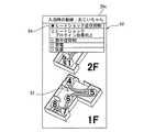
次に、ステップS7に示されるように、制御部20bは温度情報を表示部20cに表示させる。図10は、間取りと温度情報の表示方法を説明する図である。図11は、間取りと温度情報の表示方法の変形例を説明する図である。制御部20bは、複数の温度センサ30から制御装置10を介して複数の温度情報を取得すると、画像50上で複数の温度情報を複数の部屋にそれぞれ対応させて表示部20cに表示させる。 Next, as shown in step S7, the
表示部20cは、複数の部屋を複数の温度情報に基づき色分けして表示する。例えば、図10に示されるように、浴室への移動順序を示す番号が、番号が表示される部屋の温度に応じた色で表示されても良い。また、図11に示されるように、各部屋が、その部屋の温度に応じた色で表示されても良い。番号または部屋は、例えば高温から順に赤、橙、黄、緑、青で表示されても良い。 The
また、複数の温度情報は複数の部屋の温度に限らない。複数の温度情報は、複数の部屋それぞれについてのヒートショックを抑制する効果、ヒートショックプロテインの生成を促す効果、熱中症を抑制する効果、節電の効果または使用者の好みの温度を実現する効果を示す情報を含んでも良い。 Further, the plurality of temperature information is not limited to the temperatures of a plurality of rooms. Multiple temperature information has the effect of suppressing heat shock in each of multiple rooms, promoting the production of heat shock proteins, suppressing heat stroke, saving electricity, or achieving the temperature desired by the user. It may include information to indicate.
また、端末装置20は、図11に示されるように、複数の部屋に滞在している複数の使用者を、ヒートショックを抑制する効果等に応じて色分けして表示しても良い。この場合、制御装置10は、画像センサ32等により使用者の位置情報を検出し、端末装置20に送信する。また、制御装置10は使用者の行動予定と複数の部屋の現在の温度から、各使用者に対するヒートショックを抑制する効果等を導き出す。制御装置10は、ヒートショックを抑制する効果等を温度情報として、端末装置20に送信する。これにより、制御部20bは、複数の使用者の現在の位置と、ヒートショックを抑制する効果を表示部20cに表示させる。 Further, as shown in FIG. 11, the
ヒートショックを抑制する効果、ヒートショックプロテインの生成を促す効果、熱中症を抑制する効果、節電の効果または使用者の好みの温度を実現する効果は、例えば安全または効果ありの場合は橙または緑、危険または効果なしの場合は青で示される。 The effects of suppressing heat shock, promoting the production of heat shock proteins, suppressing heat stroke, saving electricity or achieving the temperature of the user's preference are, for example, orange or green if safe or effective. , Shown in blue if dangerous or ineffective.
上記の表示方法は組み合わせて用いられても良い。また、画像50上に、温度とヒートショック抑制効果とが両方示されても良い。 The above display methods may be used in combination. Further, both the temperature and the heat shock suppressing effect may be shown on the
また、端末装置20には制御装置10から複数の部屋の温度が送信され、端末装置20が複数の部屋の温度から複数の部屋それぞれについてのヒートショックを抑制する効果等を算出しても良い。また、端末装置20は、複数の温度センサ30から直接温度情報を取得しても良い。 Further, the temperature of a plurality of rooms may be transmitted from the
また、制御装置10は給湯機16から湯張りの状態を取得し、制御部20bに送信する。制御部20bは、湯張りの状態を表示部20cに表示される。湯張りの状態は、湯張りが完了したか否かの情報または、湯張り完了までの時間を含む。これにより、使用者は、湯張りの状態を表示部20cから確認できる。図10には、一例としてお風呂の準備ができた旨を知らせるメッセージが表示部20cに表示されている。 Further, the
また、図10に示されるように、表示部20cには、浴室での滞在時間のリスト55が表示される。使用者は、浴室での滞在予定時間をリスト55からタップ操作で選択する。制御部20bは、浴室での滞在予定時間を制御装置10に送信する。制御装置10は、例えば使用者が浴室から出てくる時間に合わせて、浴室に向かう際と同様に動線51上の部屋の温度を制御しても良い。 Further, as shown in FIG. 10, the
図12は、制御装置10の学習機能を説明するフローチャートである。ステップS11に示されるように、制御装置10は、画像センサ32によって使用者の移動を検出する。この際、制御装置10は、画像センサ32からの情報に基づき、移動している使用者の特定を行う。次に、ステップS12に示されるように、制御装置10は移動している使用者の場所と、移動が発生した時間を検出する。使用者の場所は、例えば画像センサ32の位置情報から取得できる。 FIG. 12 is a flowchart illustrating the learning function of the
次に、ステップS13に示されるように、制御装置10はステップS5で端末装置20から受信した行動予定と、検出した使用者の実際の行動とを比較する。予め設定された行動予定と使用者の行動とに差異がある場合、ステップS14に示されるように、制御装置10は実際の行動に合わせて、自己に記憶された行動予定を補正する。また、制御装置10は補正した行動予定を端末装置20に送信する。端末装置20は、制御装置10から受信した新たな行動予定で、メモリ22に記憶した行動予定を更新する。予め設定された行動予定と使用者の行動とに差異がない場合、行動予定の補正および送信は実施されない。 Next, as shown in step S13, the
これにより、端末装置20は新たな行動予定に合わせて、ステップS6、S7を実施する。また、制御装置10は、実際の行動に合わせて各部屋の温度の制御および湯張りを行う。このように、制御装置10は、実際の使用者の行動を学習して、行動予定を補正する。従って、自動で、制御の精度を向上できる。 As a result, the
なお、使用者の移動の検出は、使用者が携帯する端末装置20の位置センサ24で実施されても良い。この場合、ステップS11〜S14は端末装置20が実施する。端末装置20は行動予定を補正する場合、新たな行動予定を制御装置10に送信する。 The movement of the user may be detected by the
本実施の形態では、給湯機16と暖房を連動させる。これにより、ヒートショック抑制、ヒートショックプロテイン増加、熱中症抑制、節電または快適性向上の効果を得ることができる。ここで、本実施の形態では、使用者の行動予定に合わせてタイミング良く温度調節を行う。これにより、消費電力を抑制しつつ、ヒートショック抑制の効果等を得ることでできる。また、使用者の動線上の全ての部屋の温度が制御されるため、ヒートショック抑制の効果等を向上できる。特に、一般に暖房がないクローゼット等も温度調節することで、さらにヒートショック抑制の効果等を向上できる。 In the present embodiment, the
また、空調システムにおいて複数の機器をタイミング良く動作させるためには、初期設定が煩雑となることが多い。また、管理装置が人の移動および行動のタイミングを把握するためには、事前に多くの情報の入力が必要となることが多い。特に、人の移動の流れを入力するのは非常に手間がかかるおそれがある。 Further, in order to operate a plurality of devices in a timely manner in an air conditioning system, initial settings are often complicated. In addition, in order for the management device to grasp the timing of movement and action of a person, it is often necessary to input a large amount of information in advance. In particular, it can be very time-consuming to enter the flow of movement of people.
これに対し、本実施の形態では、スマートフォン等の画面へのタップ操作または画面をなぞることで、簡単に使用者が浴室に向かう動線等を入力できる。従って、入浴時の行動予定を容易に入力でき、初期設定を容易に実施できる。 On the other hand, in the present embodiment, the user can easily input a flow line or the like toward the bathroom by tapping the screen of a smartphone or the like or tracing the screen. Therefore, the action schedule at the time of bathing can be easily input, and the initial setting can be easily performed.
また、入浴開始時間および動線51上の各部屋での滞在時間を入力することで、さらに正確なタイミングで空間の温度調節および湯張りの湯温調整ができる。従って、消費電力の抑制の効果を向上できる。 Further, by inputting the bathing start time and the staying time in each room on the
また、本実施の形態では、間取りと、間取りに含まれる複数の部屋の温度情報とが対応した状態で表示される。従って、間取りに含まれる複数の部屋の温度情報を使用者が容易に把握できる。これにより、使用者は各部屋のヒートショック抑制の状態等を一目で把握できる。 Further, in the present embodiment, the floor plan and the temperature information of a plurality of rooms included in the floor plan are displayed in a corresponding state. Therefore, the user can easily grasp the temperature information of a plurality of rooms included in the floor plan. As a result, the user can grasp the state of heat shock suppression in each room at a glance.
また、温度制御システム100において、リモコン、AIスピーカー等が制御装置10により連携制御されても良い。例えば、ヒートショックまたは熱中症を抑制するための使用者へのアドバイスが、AIスピーカーから行われても良い。 Further, in the
本実施の形態の変形例として、表示部20cには、使用者が浴室から出た後の動線が入力されても良い。この場合、制御装置10は、入浴後に使用者が動線51上の部屋に到達する時間に合わせて、部屋の温度を制御する。 As a modification of the present embodiment, the flow line after the user leaves the bathroom may be input to the
また、間取り検出部20aは、制御部20bおよび表示部20cとは別の端末に設けられても良い。この場合、間取り検出部20aが検出した情報は、制御装置10に送信され、制御装置10で画像50が作成されても良い。また、端末装置20は、間取りの画像50を制御装置10から取得しても良い。 Further, the floor
また、本実施の形態は、全館空調が導入された建物において、動線上の暖かさが足りない場所または暑すぎる場所の温度調節に用いられても良い。 Further, the present embodiment may be used for temperature control in a place where the warmth on the flow line is insufficient or too hot in a building in which air conditioning is introduced in the entire building.
なお、本実施の形態で説明した技術的特徴は適宜に組み合わせて用いても良い。 The technical features described in this embodiment may be used in combination as appropriate.
10 制御装置、12 温度調節部、14 送風部、16 給湯機、20 端末装置、20a 検出部、20b 制御部、20c 表示部、20d 入力検出部、20e 通信部、21 プロセッサ、22 メモリ、23 タッチパネル、24 位置センサ、30 温度センサ、32 画像センサ、50 画像、51 動線、52〜55 リスト、100 温度制御システム 10 Control device, 12 Temperature control unit, 14 Blower, 16 Water heater, 20 Terminal device, 20a detection unit, 20b control unit, 20c display unit, 20d input detection unit, 20e communication unit, 21 processor, 22 memory, 23 touch panel , 24 position sensor, 30 temperature sensor, 32 image sensor, 50 image, 51 motion line, 52-55 list, 100 temperature control system
本願の第1の発明に係る端末装置は、画像センサまたはカメラにより空間の間取りを立体的に検出する検出部と、表示部と、該検出部が検出した情報から該間取りの画像を作成し、該間取りに含まれる複数の部屋にそれぞれ対応する複数の温度情報を取得し、該画像と該複数の温度情報とを対応させて該表示部に表示させる制御部と、を備える。The terminal device according to the first invention of the present application creates an image of the floor plan froma detection unit that three-dimensionallydetects the floor plan of the space by an image sensor or a camera , a display unit, and information detected by the detection unit. A control unit that acquires a plurality of temperature information corresponding to each of the plurality of rooms included in the floor plan, associates the image with the plurality of temperature information, and displays the image on the display unit.
本願の第2の発明に係る端末装置は、画像センサまたはカメラにより空間の間取りを立体的に検出する検出部と、表示部と、該検出部が検出した該空間の間取りの画像を該表示部に表示させる制御部と、を備え、該表示部には、タップ操作または該画像をなぞることで、使用者が浴室に向かう動線が入力される。
Terminal device according to the second aspect of the present invention,the detection unit for detecting a floor plan of the spatial three-dimensionally by the image sensor or camera and the display unit and, the display unit an image of a floor plan ofthe space detection unit detects The display unit is provided with a control unit for displaying the image, and a flow line toward the bathroom by the user is input to the display unit by tapping or tracing the image.
本願の第1の発明に係る端末装置は、画像センサまたはカメラにより空間の間取りを立体的に検出する検出部と、表示部と、該検出部が検出した情報から該間取りの立体的な画像を作成し、該間取りに含まれる複数の部屋にそれぞれ対応する複数の温度情報を取得し、該画像と該複数の温度情報とを対応させて該表示部に表示させる制御部と、を備える。Terminal device according to a first aspect of the present invention is a detector for three-dimensionally detecting the floor plan of the space by the image sensor or camera, a display unit,a three-dimensional image of該間up from the information detection unit detects It is provided with a control unit that is created, acquires a plurality of temperature information corresponding to each of the plurality of rooms included in the floor plan, and displays the image and the plurality of temperature information on the display unit in association with each other.
Claims (22)
Translated fromJapanese表示部と、
前記検出部が検出した情報から前記間取りの画像を作成し、前記間取りに含まれる複数の部屋にそれぞれ対応する複数の温度情報を取得し、前記画像と前記複数の温度情報とを対応させて前記表示部に表示させる制御部と、
を備えることを特徴とする端末装置。A detector that detects the floor plan of the space and
Display and
An image of the floor plan is created from the information detected by the detection unit, a plurality of temperature information corresponding to each of the plurality of rooms included in the floor plan is acquired, and the image and the plurality of temperature information are made to correspond to each other. The control unit to be displayed on the display unit and
A terminal device comprising.
前記制御部は、前記行動予定に応じて前記複数の温度情報を取得し、前記表示部に表示させることを特徴とする請求項1から5の何れか1項に記載の端末装置。In the display unit, the action schedule of the user at the time of bathing is input with the image displayed.
The terminal device according to any one of claims 1 to 5, wherein the control unit acquires the plurality of temperature information according to the action schedule and displays the temperature information on the display unit.
前記複数の部屋には前記動線上の部屋が含まれることを特徴とする請求項6に記載の端末装置。The action schedule includes a flow line toward the bathroom by the user.
The terminal device according to claim 6, wherein the plurality of rooms include a room on the flow line.
前記制御部は、前記時間の前記複数の温度情報を取得し、前記表示部に表示させることを特徴とする請求項6または7に記載の端末装置。The action schedule includes information on the time when the user goes to the bathroom.
The terminal device according to claim 6 or 7, wherein the control unit acquires the plurality of temperature information of the time and displays the temperature information on the display unit.
前記複数の部屋にそれぞれ設けられた複数の温度センサから前記複数の温度情報を取得し、前記複数の温度情報を前記制御部に送信する制御装置と、
を備えることを特徴とする温度制御システム。The terminal device according to any one of claims 1 to 8.
A control device that acquires the plurality of temperature information from the plurality of temperature sensors provided in the plurality of rooms and transmits the plurality of temperature information to the control unit.
A temperature control system characterized by being equipped with.
前記制御装置は、前記行動予定に応じて前記空間の温度を制御することを特徴とする請求項9に記載の温度制御システム。In the display unit, the action schedule at the time of bathing of the user is input in the state where the image is displayed.
The temperature control system according to claim 9, wherein the control device controls the temperature of the space according to the action schedule.
空間の間取りの画像を前記表示部に表示させる制御部と、
を備え、
前記表示部には、タップ操作または前記画像をなぞることで、使用者が浴室に向かう動線が入力されることを特徴とする端末装置。Display and
A control unit that displays an image of the floor plan on the display unit,
With
A terminal device characterized in that a flow line toward the bathroom is input to the display unit by tapping or tracing the image.
前記動線上の部屋の温度を制御する制御装置と、
を備えることを特徴とする温度制御システム。The terminal device according to any one of claims 11 to 16.
A control device that controls the temperature of the room on the flow line,
A temperature control system characterized by being equipped with.
前記表示部には、複数の使用者にそれぞれ対応する複数の動線が入力され、
前記制御装置は、前記複数の動線のうち、浴室に向かっている前記使用者に対応する動線に応じて前記空間の温度を制御することを特徴とする請求項17から19の何れか1項に記載の温度制御システム。Equipped with a sensor that identifies the user heading to the bathroom
A plurality of flow lines corresponding to a plurality of users are input to the display unit, and a plurality of flow lines are input to the display unit.
Any one of claims 17 to 19, wherein the control device controls the temperature of the space according to the flow line corresponding to the user toward the bathroom among the plurality of flow lines. The temperature control system described in the section.
前記制御部は、前記画像と前記複数の温度情報とを対応させて前記表示部に表示させることを特徴とする請求項17から20の何れか1項に記載の温度制御システム。The control device acquires a plurality of temperature information from a plurality of temperature sensors provided in each of the plurality of rooms included in the floor plan, and transmits the plurality of temperature information to the control unit.
The temperature control system according to any one of claims 17 to 20, wherein the control unit associates the image with the plurality of temperature information and displays the temperature information on the display unit.
Applications Claiming Priority (1)
| Application Number | Priority Date | Filing Date | Title |
|---|---|---|---|
| PCT/JP2019/020530WO2020235100A1 (en) | 2019-05-23 | 2019-05-23 | Terminal device and temperature control system |
Publications (1)
| Publication Number | Publication Date |
|---|---|
| JPWO2020235100A1true JPWO2020235100A1 (en) | 2021-06-10 |
Family
ID=73458164
Family Applications (1)
| Application Number | Title | Priority Date | Filing Date |
|---|---|---|---|
| JP2019557646APendingJPWO2020235100A1 (en) | 2019-05-23 | 2019-05-23 | Terminal device and temperature control system |
Country Status (2)
| Country | Link |
|---|---|
| JP (1) | JPWO2020235100A1 (en) |
| WO (1) | WO2020235100A1 (en) |
Families Citing this family (1)
| Publication number | Priority date | Publication date | Assignee | Title |
|---|---|---|---|---|
| CN113864970A (en)* | 2021-09-09 | 2021-12-31 | 珠海格力电器股份有限公司 | Air conditioner manual operator control processing method and device, server and air conditioning system |
Citations (8)
| Publication number | Priority date | Publication date | Assignee | Title |
|---|---|---|---|---|
| JPS59127143U (en)* | 1983-02-14 | 1984-08-27 | 株式会社マツクス製作所 | temperature monitoring system |
| JPH03291445A (en)* | 1990-04-06 | 1991-12-20 | Shimizu Corp | Hot heat environmental evaluation support system |
| WO2010013572A1 (en)* | 2008-07-28 | 2010-02-04 | 国立大学法人筑波大学 | Built-in control system |
| JP2013076493A (en)* | 2011-09-30 | 2013-04-25 | Hitachi Appliances Inc | Air conditioner control terminal and method of setting operation for air conditioning control |
| JP2014049081A (en)* | 2012-09-04 | 2014-03-17 | Nippon Telegr & Teleph Corp <Ntt> | Apparatus arrangement determination system, apparatus arrangement determination method, and apparatus arrangement determination program |
| WO2014128784A1 (en)* | 2013-02-20 | 2014-08-28 | パナソニック インテレクチュアル プロパティ コーポレーション オブ アメリカ | Program and method for controlling portable information terminal |
| JP2015121946A (en)* | 2013-12-24 | 2015-07-02 | グンゼ株式会社 | Gas detection system |
| JP2018063537A (en)* | 2016-10-12 | 2018-04-19 | 株式会社東芝 | Home network, electronic apparatus, processing device and display method |
- 2019
- 2019-05-23JPJP2019557646Apatent/JPWO2020235100A1/enactivePending
- 2019-05-23WOPCT/JP2019/020530patent/WO2020235100A1/ennot_activeCeased
Patent Citations (8)
| Publication number | Priority date | Publication date | Assignee | Title |
|---|---|---|---|---|
| JPS59127143U (en)* | 1983-02-14 | 1984-08-27 | 株式会社マツクス製作所 | temperature monitoring system |
| JPH03291445A (en)* | 1990-04-06 | 1991-12-20 | Shimizu Corp | Hot heat environmental evaluation support system |
| WO2010013572A1 (en)* | 2008-07-28 | 2010-02-04 | 国立大学法人筑波大学 | Built-in control system |
| JP2013076493A (en)* | 2011-09-30 | 2013-04-25 | Hitachi Appliances Inc | Air conditioner control terminal and method of setting operation for air conditioning control |
| JP2014049081A (en)* | 2012-09-04 | 2014-03-17 | Nippon Telegr & Teleph Corp <Ntt> | Apparatus arrangement determination system, apparatus arrangement determination method, and apparatus arrangement determination program |
| WO2014128784A1 (en)* | 2013-02-20 | 2014-08-28 | パナソニック インテレクチュアル プロパティ コーポレーション オブ アメリカ | Program and method for controlling portable information terminal |
| JP2015121946A (en)* | 2013-12-24 | 2015-07-02 | グンゼ株式会社 | Gas detection system |
| JP2018063537A (en)* | 2016-10-12 | 2018-04-19 | 株式会社東芝 | Home network, electronic apparatus, processing device and display method |
Also Published As
| Publication number | Publication date |
|---|---|
| WO2020235100A1 (en) | 2020-11-26 |
Similar Documents
| Publication | Publication Date | Title |
|---|---|---|
| US10151501B2 (en) | Thermostat facilitating user-friendly installation thereof | |
| JP6046579B2 (en) | Air conditioner | |
| TWI546506B (en) | Controlling system for environmental comfort value and controlling method of the controlling system | |
| CN104501354B (en) | The method of adjustment and system of air conditioner air supply mode | |
| CN110671798A (en) | Indoor thermal environment control system for predicting thermal sensation based on artificial intelligence technology | |
| JP6257701B2 (en) | Air conditioning system | |
| CN113906260B (en) | Air conditioner control device and air conditioner control system | |
| CN106597863A (en) | System for dynamic control with interactive visualization to optimize energy consumption | |
| JP6298323B2 (en) | Temperature environment control system and apparatus | |
| JP4757105B2 (en) | Residential monitoring system and housing | |
| HK1214059A1 (en) | Energy management controller, energy management system, energy management method, and program | |
| JPWO2020235100A1 (en) | Terminal device and temperature control system | |
| JP6410435B2 (en) | Window opening and closing system | |
| JP6171579B2 (en) | Equipment and equipment management system | |
| JP2018189329A (en) | Air conditioning system of building | |
| JP2021032459A (en) | Air conditioning system | |
| JP2020188992A (en) | Notification system | |
| JP7527363B2 (en) | Control system, facility equipment system, and facility equipment control method | |
| KR20190088100A (en) | System for energy saving and method thereof | |
| JP7294953B2 (en) | bathroom air conditioning system | |
| JP2013029275A (en) | Control device, and control system | |
| JP5504372B1 (en) | Air conditioning system control device, air conditioning system and building | |
| WO2015173931A1 (en) | Home electric appliance control apparatus | |
| JP7259277B2 (en) | water heater | |
| JP2024082571A (en) | Device control system, program, and device control method |
Legal Events
| Date | Code | Title | Description |
|---|---|---|---|
| A521 | Request for written amendment filed | Free format text:JAPANESE INTERMEDIATE CODE: A523 Effective date:20191023 | |
| A621 | Written request for application examination | Free format text:JAPANESE INTERMEDIATE CODE: A621 Effective date:20191023 | |
| A871 | Explanation of circumstances concerning accelerated examination | Free format text:JAPANESE INTERMEDIATE CODE: A871 Effective date:20191023 | |
| A975 | Report on accelerated examination | Free format text:JAPANESE INTERMEDIATE CODE: A971005 Effective date:20191204 | |
| A131 | Notification of reasons for refusal | Free format text:JAPANESE INTERMEDIATE CODE: A131 Effective date:20200212 | |
| A521 | Request for written amendment filed | Free format text:JAPANESE INTERMEDIATE CODE: A523 Effective date:20200316 | |
| A02 | Decision of refusal | Free format text:JAPANESE INTERMEDIATE CODE: A02 Effective date:20200616 |