JPWO2020213036A1 - Roadside communication device and road-to-vehicle communication method - Google Patents
Roadside communication device and road-to-vehicle communication methodDownload PDFInfo
- Publication number
- JPWO2020213036A1 JPWO2020213036A1JP2019554949AJP2019554949AJPWO2020213036A1JP WO2020213036 A1JPWO2020213036 A1JP WO2020213036A1JP 2019554949 AJP2019554949 AJP 2019554949AJP 2019554949 AJP2019554949 AJP 2019554949AJP WO2020213036 A1JPWO2020213036 A1JP WO2020213036A1
- Authority
- JP
- Japan
- Prior art keywords
- communication
- unit
- vehicle
- reception intensity
- angle
- Prior art date
- Legal status (The legal status is an assumption and is not a legal conclusion. Google has not performed a legal analysis and makes no representation as to the accuracy of the status listed.)
- Granted
Links
Images


Classifications
- H—ELECTRICITY
- H04—ELECTRIC COMMUNICATION TECHNIQUE
- H04W—WIRELESS COMMUNICATION NETWORKS
- H04W4/00—Services specially adapted for wireless communication networks; Facilities therefor
- H04W4/30—Services specially adapted for particular environments, situations or purposes
- H04W4/40—Services specially adapted for particular environments, situations or purposes for vehicles, e.g. vehicle-to-pedestrians [V2P]
- H04W4/44—Services specially adapted for particular environments, situations or purposes for vehicles, e.g. vehicle-to-pedestrians [V2P] for communication between vehicles and infrastructures, e.g. vehicle-to-cloud [V2C] or vehicle-to-home [V2H]
- G—PHYSICS
- G01—MEASURING; TESTING
- G01S—RADIO DIRECTION-FINDING; RADIO NAVIGATION; DETERMINING DISTANCE OR VELOCITY BY USE OF RADIO WAVES; LOCATING OR PRESENCE-DETECTING BY USE OF THE REFLECTION OR RERADIATION OF RADIO WAVES; ANALOGOUS ARRANGEMENTS USING OTHER WAVES
- G01S3/00—Direction-finders for determining the direction from which infrasonic, sonic, ultrasonic, or electromagnetic waves, or particle emission, not having a directional significance, are being received
- G01S3/02—Direction-finders for determining the direction from which infrasonic, sonic, ultrasonic, or electromagnetic waves, or particle emission, not having a directional significance, are being received using radio waves
- G01S3/14—Systems for determining direction or deviation from predetermined direction
- G01S3/46—Systems for determining direction or deviation from predetermined direction using antennas spaced apart and measuring phase or time difference between signals therefrom, i.e. path-difference systems
- G—PHYSICS
- G01—MEASURING; TESTING
- G01S—RADIO DIRECTION-FINDING; RADIO NAVIGATION; DETERMINING DISTANCE OR VELOCITY BY USE OF RADIO WAVES; LOCATING OR PRESENCE-DETECTING BY USE OF THE REFLECTION OR RERADIATION OF RADIO WAVES; ANALOGOUS ARRANGEMENTS USING OTHER WAVES
- G01S3/00—Direction-finders for determining the direction from which infrasonic, sonic, ultrasonic, or electromagnetic waves, or particle emission, not having a directional significance, are being received
- G01S3/02—Direction-finders for determining the direction from which infrasonic, sonic, ultrasonic, or electromagnetic waves, or particle emission, not having a directional significance, are being received using radio waves
- G01S3/74—Multi-channel systems specially adapted for direction-finding, i.e. having a single antenna system capable of giving simultaneous indications of the directions of different signals
- G—PHYSICS
- G07—CHECKING-DEVICES
- G07B—TICKET-ISSUING APPARATUS; FARE-REGISTERING APPARATUS; FRANKING APPARATUS
- G07B15/00—Arrangements or apparatus for collecting fares, tolls or entrance fees at one or more control points
- G—PHYSICS
- G08—SIGNALLING
- G08G—TRAFFIC CONTROL SYSTEMS
- G08G1/00—Traffic control systems for road vehicles
- G08G1/09—Arrangements for giving variable traffic instructions
- G—PHYSICS
- G01—MEASURING; TESTING
- G01S—RADIO DIRECTION-FINDING; RADIO NAVIGATION; DETERMINING DISTANCE OR VELOCITY BY USE OF RADIO WAVES; LOCATING OR PRESENCE-DETECTING BY USE OF THE REFLECTION OR RERADIATION OF RADIO WAVES; ANALOGOUS ARRANGEMENTS USING OTHER WAVES
- G01S3/00—Direction-finders for determining the direction from which infrasonic, sonic, ultrasonic, or electromagnetic waves, or particle emission, not having a directional significance, are being received
- G01S3/02—Direction-finders for determining the direction from which infrasonic, sonic, ultrasonic, or electromagnetic waves, or particle emission, not having a directional significance, are being received using radio waves
- G01S3/04—Details
- G01S3/043—Receivers
- G—PHYSICS
- G01—MEASURING; TESTING
- G01S—RADIO DIRECTION-FINDING; RADIO NAVIGATION; DETERMINING DISTANCE OR VELOCITY BY USE OF RADIO WAVES; LOCATING OR PRESENCE-DETECTING BY USE OF THE REFLECTION OR RERADIATION OF RADIO WAVES; ANALOGOUS ARRANGEMENTS USING OTHER WAVES
- G01S3/00—Direction-finders for determining the direction from which infrasonic, sonic, ultrasonic, or electromagnetic waves, or particle emission, not having a directional significance, are being received
- G01S3/02—Direction-finders for determining the direction from which infrasonic, sonic, ultrasonic, or electromagnetic waves, or particle emission, not having a directional significance, are being received using radio waves
- G01S3/14—Systems for determining direction or deviation from predetermined direction
- G01S3/46—Systems for determining direction or deviation from predetermined direction using antennas spaced apart and measuring phase or time difference between signals therefrom, i.e. path-difference systems
- G01S3/48—Systems for determining direction or deviation from predetermined direction using antennas spaced apart and measuring phase or time difference between signals therefrom, i.e. path-difference systems the waves arriving at the antennas being continuous or intermittent and the phase difference of signals derived therefrom being measured
Landscapes
- Engineering & Computer Science (AREA)
- Physics & Mathematics (AREA)
- General Physics & Mathematics (AREA)
- Radar, Positioning & Navigation (AREA)
- Remote Sensing (AREA)
- Computer Networks & Wireless Communication (AREA)
- Signal Processing (AREA)
- Business, Economics & Management (AREA)
- Finance (AREA)
- Mobile Radio Communication Systems (AREA)
- Traffic Control Systems (AREA)
- Devices For Checking Fares Or Tickets At Control Points (AREA)
Abstract
Translated fromJapaneseDescription
Translated fromJapanese本発明は、路側通信装置および路車間通信方法に関する。 The present invention relates to a roadside communication device and a road-to-vehicle communication method.
ETC(Electronic Toll Control system)(登録商標)といった路車間通信システムでは、道路を走行する車両に搭載された車載器と、路側に設置された路側通信装置との間で様々な情報が送受されている。路側通信装置は、車載器から送出された電波の受信強度(Received Signal Strength Indicator;以下、RSSIと略して記載する)が基準値を超えた場合、車載器との通信を確立している。このため、通信対象の車載器の周辺に存在する、通信対象ではない車載器から送信された電波のRSSIが基準値を超えることによって、路側通信装置は、通信対象ではない車載器と誤通信する可能性がある。 In a road-to-vehicle communication system such as ETC (Electronic Toll Control System) (registered trademark), various information is transmitted and received between an on-board unit mounted on a vehicle traveling on a road and a roadside communication device installed on the roadside. There is. The roadside communication device establishes communication with the on-board unit when the reception intensity (Received Signal Strength Indicator; hereinafter abbreviated as RSSI) of the radio wave transmitted from the on-board unit exceeds the reference value. Therefore, when the RSSI of the radio wave transmitted from the vehicle-mounted device that is not the communication target and exists in the vicinity of the vehicle-mounted device that is the communication target exceeds the reference value, the roadside communication device erroneously communicates with the vehicle-mounted device that is not the communication target. there is a possibility.
この問題に対して、例えば、特許文献1には、車載器との通信に用いる通信用アンテナに加え、電波の到来角を特定するための方位特定用アンテナを備えた情報処理装置が記載されている。この情報処理装置は、方位特定用アンテナによって受信された電波の到来角を推定し、推定された到来角に基づいて電波の送信元の車載器が対象のレーンを走行している車両に搭載された車載器であるか否かを判定する。 To solve this problem, for example, Patent Document 1 describes an information processing device provided with an antenna for specifying an orientation for specifying an arrival angle of a radio wave in addition to a communication antenna used for communication with an in-vehicle device. There is. This information processing device estimates the arrival angle of the radio wave received by the directional identification antenna, and is mounted on the vehicle in which the on-board unit that is the source of the radio wave is traveling in the target lane based on the estimated arrival angle. It is determined whether or not the device is an in-vehicle device.
車載器から送信された電波は、周辺の車両または建物においてマルチパス反射を起こすことがある。特許文献1に記載された情報処理装置では、電波が反射波で受信されることが考慮されていないため、車載器から送信された電波の直接波と反射波が混在した状態で受信された場合、電波の到来角を正確に推定できないという課題があった。電波の到来角を正確に推定できない場合、通信対象ではない車載器と誤通信する可能性がある。 Radio waves transmitted from the on-board unit may cause multipath reflection in surrounding vehicles or buildings. In the information processing device described in Patent Document 1, since it is not considered that the radio wave is received by the reflected wave, when the direct wave and the reflected wave of the radio wave transmitted from the vehicle-mounted device are received in a mixed state. , There was a problem that the arrival angle of radio waves could not be estimated accurately. If the arrival angle of radio waves cannot be estimated accurately, there is a possibility of erroneous communication with an in-vehicle device that is not the communication target.
本発明は上記課題を解決するものであって、通信対象ではない車載器との誤通信を回避することができる路側通信装置および路車間通信方法を得ることを目的とする。 The present invention solves the above problems, and an object of the present invention is to obtain a roadside communication device and a road-to-vehicle communication method capable of avoiding erroneous communication with an in-vehicle device that is not a communication target.
本発明に係る路側通信装置は、車載器との通信に用いられる第1のアンテナと、電波の到来角の推定に用いられる第2のアンテナに接続される路側通信装置であって、第1のアンテナを通じて車載器から受信された電波の受信強度を検出する通信処理部と、第2のアンテナを通じて車載器から受信された電波の、直接波の到来角および受信強度と、反射波の到来角および受信強度とを推定する測角部と、通信処理部によって検出された受信強度と、測角部によって推定された電波の直接波の到来角および受信強度と反射波の到来角および受信強度とに基づいて、第1のアンテナを用いた通信処理部による車載器との通信可否を判定する判定部を備える。 The roadside communication device according to the present invention is a roadside communication device connected to a first antenna used for communication with an in-vehicle device and a second antenna used for estimating an arrival angle of radio waves. The communication processing unit that detects the reception intensity of the radio wave received from the in-vehicle device through the antenna, the direct wave arrival angle and reception intensity of the radio wave received from the in-vehicle device through the second antenna, the arrival angle of the reflected wave, and The angle measuring unit that estimates the reception intensity, the reception intensity detected by the communication processing unit, and the arrival angle and reception intensity of the direct wave of the radio wave estimated by the angle measurement unit, and the arrival angle and reception intensity of the reflected wave. Based on this, a determination unit for determining whether or not communication with the in-vehicle device is possible by the communication processing unit using the first antenna is provided.
本発明によれば、第1のアンテナを通じて受信された電波から検出された受信強度と、第2のアンテナを通じて受信された電波から推定された直接波の到来角および受信強度と反射波の到来角および電波受信強度とに基づいて、第1のアンテナを通じた車載器との通信可否が判定される。これにより、車載器から送信された電波の直接波と反射波が混在した状態で受信されても、通信対象ではない車載器との誤通信を回避することができる。 According to the present invention, the reception intensity detected from the radio wave received through the first antenna, the arrival angle of the direct wave estimated from the radio wave received through the second antenna, the reception intensity, and the arrival angle of the reflected wave. Based on the radio wave reception strength and the radio wave reception strength, it is determined whether or not communication with the vehicle-mounted device is possible through the first antenna. As a result, even if the direct wave and the reflected wave of the radio wave transmitted from the vehicle-mounted device are received in a mixed state, erroneous communication with the vehicle-mounted device that is not the communication target can be avoided.
実施の形態1.
図1は、実施の形態1に係る路側通信装置100の構成を示すブロック図である。路側通信装置100は、路側に設けられて、車両に搭載された車載器との通信を行う。また、従来から、通信対象外の車載器から送信された電波を電波吸収体に吸収させることが一般に行われていたが、路側通信装置100は、車載器から送信された電波の直接波の到来角および受信強度と反射波の到来角および受信強度とを用いて、車載器との通信可否を判定する。従って、路側通信装置100は、通信対象外の車載器から送信された電波を吸収するための電波吸収体を用いることなく、通信対象外の車載器との誤通信を回避することができる。Embodiment 1.
FIG. 1 is a block diagram showing a configuration of a
通信用アンテナ101は、車載器との通信に用いられる第1のアンテナであり、通信処理部102が有する通信部103aと復調部103bとに接続されている。例えば、通信用アンテナ101を通じて、通信制御情報チャンネルとサービス情報とを含む電波が車載器に送信され、車載器の応答信号が受信される。通信制御情報チャンネルは、FCMC(Frame Control Message Channel)であり、サービス情報は、BST(Beacon Service Table)である。また、車載器からの応答信号には、ACTC(Activation Channel)およびVST(Vehicle Service Table)がある。 The
通信処理部102は、通信用アンテナ101を通じて車載器から受信された電波の受信強度を検出する。また、通信処理部102は、通信判定部106によって車載器との通信可と判定された場合に、通信用アンテナ101を用いた車載器との通信を行う。通信処理部102は、通信部103aと復調部103bとを有する。通信部103aは、FCMCの情報に基づいて、送信信号を変調し、変調された送信信号を周波数変換し、周波数変換された送信信号を増幅する。これらの処理が施された送信信号は、通信部103aから通信用アンテナ101に出力され、通信用アンテナ101を通じて車載器に向けて送信される。 The
復調部103bは、通信用アンテナ101を通じて車載器から受信された電波を復調し、復調された電波を解析して、車載器IDおよび電波の受信強度を検出する。復調部103bは、検出した車載器IDおよび電波の受信強度を通信判定部106に出力する。車載器IDは、電波の送信元の車載器を識別するために付与された当該車載器に固有な情報である。例えば、車載器IDは、車載器から路側通信装置100に送信されるACTCに含まれる。また、電波の受信強度は、車載器から受信された電波のRSSIである。 The
測角用アンテナ104は、車載器から受信された電波の到来角の推定に用いられる第2のアンテナであり、高分解能測角部105に接続されている。測角用アンテナ104は、アレーアンテナであり、複数の素子アンテナ107を備えている。 The
高分解能測角部105は、測角用アンテナ104を通じて車載器から受信された電波の、直接波の到来角および受信強度と、反射波の到来角および受信強度とを推定する測角部である。高分解能測角部105は、測角用アンテナ104を通じて車載器から受信された電波を復調し、復調された電波から車載器IDを検出する。また、高分解能測角部105は、復調された電波を直接波と反射波とに分離する。そして、高分解能測角部105は、直接波の水平角および垂直角を推定するとともに、反射波の水平角および垂直角を推定する。なお、水平角と垂直角は、いずれも電波の到来角を示すものである。さらに、高分解能測角部105は、直接波の受信強度と反射波の受信強度を推定する。以下、電波の水平角の推定値および垂直角の推定値を、適宜「測角値」と記載する。また、電波の受信強度の推定値を「電波強度推定値」と記載する。高分解能測角部105は、車載器IDと、直接波の測角値および電波強度推定値と、反射波の測角値および電波強度推定値とを、通信判定部106に出力する。 The high-resolution
通信判定部106は、通信処理部102によって検出された受信強度と、高分解能測角部105によって推定された電波の直接波の到来角および受信強度と反射波の到来角および受信強度に基づいて、通信用アンテナ101を用いた通信処理部102による車載器との通信可否を判定する判定部である。例えば、通信判定部106は、復調部103bによって検出された電波の受信強度が閾値を超えており、かつ高分解能測角部105によって推定された電波の直接波の測角値または反射波の測角値のうち、いずれかの測角値が通信エリアからの到来を示している場合に、車載器との通信が可であると判定する。 The
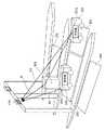
図2は、路側通信装置100を備えた路車間通信システムの概要を示す概要図である。図2に示す路車間通信システムは、ETC(登録商標)の料金所に設けられたシステムであり、路側通信装置100を備える。この料金所を通る2本のレーンのうち、一方のレーンを車両200が走行しており、車両200に続いて車両201が走行している。路側通信装置100は、エリア202〜205のいずれかに存在する車載器からの電波を受信可能である。また、料金所には、路側通信装置100が設けられたゲートと、ゲート近傍に設けられたブース206がある。 FIG. 2 is a schematic diagram showing an outline of a road-to-vehicle communication system provided with a
例えば、路側通信装置100は、通信エリアであるエリア203内に存在する車両200に搭載された車載器200aが通信対象である。しかしながら、エリア203の後方にあるエリア205内に車両201が進入すると、路側通信装置100は、車載器200aから送信された電波の直接波D1の他に、車両201に搭載された車載器201aから送信された電波の直接波D2と、車載器201aから送信された電波がブース206で反射された反射波Rが受信可能となる。このため、直接波D2あるいは反射波RのRSSIが閾値を超えると、路側通信装置100は、通信対象ではない車載器201aと誤通信する可能性がある。 For example, in the
例えば、車載器から送信されるACTCを含む電波は、基本的に車載器ごとに時分割で送信されるので、車載器同士で電波が混信することはない。従来の路側通信装置は、車載器から受信されたACTCを含む電波の到来角を推定し、推定された到来角に基づいて、車載器がエリア203内にあるか否かを判定する。しかしながら、従来の路側通信装置では、図2に示すように、通信対象ではない車載器201aから送信された電波の直接波D2と反射波Rが混在した状態で受信されると、電波の到来角を正確に推定できなくなる。 For example, the radio waves including ACTC transmitted from the on-board unit are basically transmitted in time division for each on-board unit, so that the radio waves do not interfere with each other. The conventional roadside communication device estimates the arrival angle of the radio wave including the ACTC received from the vehicle-mounted device, and determines whether or not the vehicle-mounted device is in the
そこで、路側通信装置100は、測角用アンテナ104を通じて受信された電波を直接波D2と反射波Rに分離し、分離された直接波D2と反射波Rの到来角を推定する。これにより、路側通信装置100は、車載器から送信された電波が直接波と反射波が混在した状態で受信されても、車載器との通信可否を正確に判定することができる。 Therefore, the
高分解能測角部105は、測角用アンテナ104を通じて車載器から受信された電波を直接波と反射波とに分離して高分解能測角を行う。高分解能測角方法としては、例えば、MUSIC(MUltiple SIgnal Classification)またはESPRIT(Estimation Signal Parameters via Rotational Invariance Technique)がある。これらの方法は、下記の参考文献1に詳しく記載されている。
(参考文献1)H. Krim, M. Viberg, “Two Decades of Array Signal Processing Research” ,IEEE Signal Processing Magazine, vol. 13, no.4, pp.67−94, July 1996.The high-resolution
(Reference 1) H. Krim, M.M. Viberg, “Two Decades of Array Signal Processing Research”, IEEE Signal Processing Magazine, vol. 13, no. 4, pp. 67-94, July 1996.
電波の直接波と反射波は一般に相関が高く、コヒーレント波と呼ばれる。コヒーレント波を分離して測角する方法には、例えば、空間平均法またはForward/Backward(F/B)平均法がある。空間平均法では、例えば、アレーアンテナの一部である部分アレーの相関行列と、この部分アレーを平行移動させたアレーの相関行列を平均することで、直接波と反射波の相関が抑圧される。また、F/B平均法では、反転させる前のアレーアンテナの相関行列と、このアレーアンテナを反転させた後の相関行列を平均することで、直接波と反射波の相関が抑圧される。 The direct wave and the reflected wave of radio waves are generally highly correlated and are called coherent waves. Methods for separating and measuring coherent waves include, for example, the spatial averaging method or the Forward / Backward (F / B) averaging method. In the spatial averaging method, for example, the correlation between the direct wave and the reflected wave is suppressed by averaging the correlation matrix of the partial array that is a part of the array antenna and the correlation matrix of the array that is translated by translating this partial array. .. Further, in the F / B averaging method, the correlation between the direct wave and the reflected wave is suppressed by averaging the correlation matrix of the array antenna before inversion and the correlation matrix after inversion of the array antenna.
なお、空間平均法による直接波と反射波の相関抑圧効果を向上させるためには、アレーアンテナを構成する素子アンテナ数が多いことが望ましい。しかしながら、素子アンテナ数を増加させると、装置規模が増大し、さらに、測角処理の演算量も増加する。そこで、直接波と反射波の2波入射モデルが想定される場合、高分解能測角部105は、空間平均法よりも演算量が少ないF/B平均法を用いて電波の直接波と反射波を分離し、それぞれの水平角と垂直角を推定する。 In order to improve the correlation suppression effect between the direct wave and the reflected wave by the spatial averaging method, it is desirable that the number of element antennas constituting the array antenna is large. However, when the number of element antennas is increased, the scale of the device is increased, and the calculation amount of the angle measurement processing is also increased. Therefore, when a two-wave incident model of a direct wave and a reflected wave is assumed, the high-resolution
図3は、アレーアンテナにおける素子アンテナ107の配列を示す図であって、測角用アンテナ104における素子アンテナ107の配列を示している。図3において、X軸、Y軸およびZ軸は、3次元空間内の直交座標系を表しており、Y軸の負の方向が車両の進行方向である。図3において、複数の素子アンテナ107は、いずれもX−Z面上に位置している。F/B平均法を適用するためには、アレーアンテナの素子アンテナ107の配列が、図3に示すようにアレー中心108に対して点対称である必要がある。また、互いに隣り合う素子アンテナ107同士の間隔dは、通常、送信電波の波長の半分程度に設定される。 FIG. 3 is a diagram showing the arrangement of the
図4Aは、アレーアンテナにおける素子アンテナ107の配列の変形例1を示す図である。図4Bは、アレーアンテナにおける素子アンテナ107の配列の変形例2を示す図である。図4Aおよび図4Bに示すアレーアンテナは、いずれも測角用アンテナ104であり、6つの素子アンテナ107がアレー中心に対して点対称に配列されている。 FIG. 4A is a diagram showing a modified example 1 of the arrangement of the
また、図3において、アレー中心108に向かう矢印は、車載器から送信された電波を示すベクトルである。高分解能測角部105は、測角用アンテナ104を通じて受信された電波の水平角θと垂直角φを推定する。水平角θは、水平面であるX−Y面上のY軸を基準とした当該水平面上の電波の到来角である。水平角θは、前述の電波を示すベクトルをX−Y面に正射影してできる直線とY軸とがなす角度と等しい。垂直角φは、X−Y面と基準とした電波の到来角である。垂直角φは、前述の電波を示すベクトルをX−Y面に正射影してできる直線と当該ベクトルとがなす角と等しい。 Further, in FIG. 3, the arrow toward the
図4Cは、アレーアンテナにおける通信用アンテナ101と測角用アンテナ104の構成を示す図である。図4Cに示すように、通信用アンテナ101は、例えば、複数の素子アンテナ107から構成されたアレーアンテナであってもよい。通信用アンテナ101がアレーアンテナである場合、測角用アンテナ104は、アレーアンテナの開口の一部(例えば、4つの素子アンテナ107を有する部分アレー)で構成することができる。 FIG. 4C is a diagram showing the configuration of the
車載器との通信に用いられる通信用アンテナは、通常、多数の素子アンテナを合成することでビームが形成され、形成されたビームによって通信エリアにある相手と通信できるように構成されている。このため、図4Cに示したように、多数の素子アンテナ107のうちの一部が測角用アンテナ104として利用されても、通信用アンテナ101への影響は軽微である。これは、既存の路側通信装置が備える通信用アンテナを利用して測角機能を追加できることを意味する。なお、実施の形態1は、1つのアレーアンテナから構成された通信用アンテナ101および測角用アンテナ104に限定されるものではなく、通信用アンテナ101を構成するアレーアンテナと、測角用アンテナ104を構成するアレーアンテナを別々に設けてもよい。 A communication antenna used for communication with an on-board unit is usually configured so that a beam is formed by synthesizing a large number of element antennas and the formed beam can communicate with a partner in a communication area. Therefore, as shown in FIG. 4C, even if a part of the large number of
次に、路側通信装置100を用いた路車間通信方法について説明する。
図5は、実施の形態1に係る路車間通信方法を示すフローチャートであって、路側通信装置100による一連の処理を示している。復調部103bは、通信用アンテナ101を通じて車載器から受信された電波を復調して車載器IDおよび電波受信強度を検出する(ステップST1)。例えば、復調部103bは、通信用アンテナ101を通じて受信されたACTC信号を増幅し、帯域制限フィルタに通し、中間周波数帯の信号(以下、IF信号と記載する)に周波数変換する。続いて、復調部103bは、IF信号をA/D変換してデジタル信号に変換し、デジタル信号をベースバンド信号に変換して復調する。復調部103bは、ベースバンド信号から車載器IDを検出し、ベースバンド信号を用いて電波の受信強度を検出する。Next, a road-to-vehicle communication method using the
FIG. 5 is a flowchart showing the road-to-vehicle communication method according to the first embodiment, and shows a series of processes by the
高分解能測角部105は、測角用アンテナ104を通じて受信された電波を復調して解析することで、車載器IDを検出するとともに、電波の直接波と反射波の到来角および電波強度推定値を推定する(ステップST2)。例えば、高分解能測角部105は、測角用アンテナ104を通じて車載器から受信されたACTC信号を増幅し、増幅されたACTC信号を帯域制限フィルタに通し、帯域制限フィルタを通過したACTC信号をIF信号に周波数変換する。続いて、高分解能測角部105は、IF信号をA/D変換してデジタル信号に変換し、デジタル信号をベースバンド信号に変換して復調する。高分解能測角部105は、ベースバンド信号から車載器IDを検出する。 The high-resolution
続いて、高分解能測角部105は、ACTC信号に高分解能測角処理を行って、水平角θと垂直角φを推定する。以下、測角用アンテナ104を構成する素子アンテナ107の数が4つであり、高分解能測角方法として、ESPRITアルゴリズムを採用した場合について説明する。なお、この場合に限定されるものではなく、5つ以上の素子アンテナで測角用アンテナ104を構成してもよく、高分解能測角方法には、ESPRITの代わりに、MUSICまたはCAPONを用いてもよい。 Subsequently, the high-resolution
また、F/B平均法の代わりに、2DユニタリESPRIT法について説明する。2DユニタリESPRIT法は、ユニタリ変換を用いて、電波の水平角θと垂直角φとを同時に推定することが可能であり、下記の参考文献2に詳しく記載されている。
(参考文献2)M. D. Zoltowski, M. Haardt and C. P. Mathews, “Closed−Form 2−D Angle Estimation with Rectangular Arrays in Element Space or Beamspace via Unitary ESPRIT” ,IEEE Trans., vol. SP−44, no.2, pp.316−328, Feb. 1996.Further, instead of the F / B averaging method, the 2D unitary ESPRIT method will be described. The 2D unitary ESPRIT method can estimate the horizontal angle θ and the vertical angle φ of a radio wave at the same time by using unitary transformation, and is described in detail in Reference 2 below.
(Reference 2) M.I. D. Zoltowski, M.D. Haardt and C.I. P. Mathews, "Closed-Form 2-D Angle Estimation with Rectangle Arrays in Elements Space or Beamspace Via United Esprit", IEEE Trans. , Vol. SP-44, no. 2, pp. 316-328, Feb. 1996.
高分解能測角部105は、測角用アンテナ104の各素子アンテナ107を通じて受信された電波から得られたデジタルデータxm(n)を用いて、下記式(1)から相関行列Rxxを算出する。素子番号mは、素子アンテナ107ごとに割り当てられた通し番号であり、m=1,2,3,・・・,Mが順に素子アンテナ107に割り当てられる。また、サンプリングデータ番号nは、サンプリングされたデータごとに割り当てられた通し番号であり、n=1,2,・・・,Nが順にデータに割り当てられる。x(n)は、下記式(2)で表される。(・)Tは、ベクトルまたは行列の転置であり、(・)Hは、ベクトルまたは行列のエルミート転置である。
次に、高分解能測角部105は、下記式(3)で表されるユニタリ行列Q4を用いて、下記式(4)に従い、相関行列Rxxに対してユニタリ変換を施す。下記式(4)において、Re{ }は、{ }内の実部を取ることを示す関数である。相関行列Rxxに対してユニタリ変換を施すことで、F/B平均と同様の効果が生じ、かつ、相関行列Rxxを実数化することができる。これにより、これに続く信号処理の演算量が低減される。
次に、高分解能測角部105は、実数化された相関行列Ryyを、下記式(5)に従い固有値展開する。下記式(5)において、行列Eは、固有ベクトルを並べた行列であり、対角行列Λは、対角項に固有値が並んだ行列である。ETは、行列Eの転置行列である。
高分解能測角部105は、相関行列Ryyを固有値展開して得られた固有値の分布から到来信号の波数を推定し、固有ベクトルを信号部分空間ESと雑音部分空間ENとに分離する。例えば、閾値判定による到来波信号の検出回数から、到来波信号の波数を推定することができ、閾値には、最小固有値に予め設定された一定値を乗算した値、全ての固有値の平均値、または、相乗平均値を用いることができる。High-resolution
ユニタリESPRIT法では、アレーアンテナから2つのサブアレー#1および#2が取り出され、サブアレー#1とサブアレー#2との間の位相回転行列Φを推定することにより、電波の到来角が算出される。位相回転行列Φを推定するために、サブアレー#1の信号部分空間EXとサブアレー#2の信号部分空間EYとを関係付ける変換行列Ψが算出される。In the unitary ESPRIT method, two sub-arrays # 1 and # 2 are taken out from the array antenna, and the arrival angle of the radio wave is calculated by estimating the phase rotation matrix Φ between the sub-array # 1 and the sub-array # 2. To estimate the phase rotation matrix [Phi, transformation matrix Ψ relating the subarray # 1 signal subspace EX and subarray # 2 signal subspace EY is calculated.
2DユニタリESPRIT法では、水平角θと垂直角φとを同時に推定するため、下記式(6)および(7)に示すような、水平方向に抽出されたサブアレーの信号部分空間の関係式が利用される。下記式(6)は、固有ベクトルの信号部分空間ESを用いて、水平方向に抽出されたサブアレー#1の信号部分空間EXuを算出する関係式であり、Ku1は下記式(8)で表される。また、下記式(7)は、固有ベクトルの信号部分空間ESを用いて、水平方向に抽出されたサブアレー#2の信号部分空間EYuを算出する関係式であり、Ku2は下記式(9)で表される。
さらに、2DユニタリESPRIT法では、水平角θと垂直角φとを同時に推定するため、下記式(10)および(11)に示すような、垂直方向に抽出されたサブアレーの信号部分空間の関係式が利用される。下記式(10)は、固有ベクトルの信号部分空間ESを用いて、垂直方向に抽出されたサブアレー#1の信号部分空間EXvを算出する関係式であり、Kv1は下記式(12)で表される。また、下記式(11)は、固有ベクトルの信号部分空間ESを用いて、垂直方向に抽出されたサブアレー#2の信号部分空間EYvを算出する関係式であり、Kv2は下記式(13)で表される。
高分解能測角部105は、前述のようにして算出された各サブアレーの信号部分空間を用いて、下記式(14)から、水平方向に抽出されたサブアレーに関する変換行列Ψuを算出し、下記式(15)から、垂直方向に抽出されたサブアレーに関する変換行列Ψvを算出する。
次に、水平方向の角度値と垂直方向の角度値とのペアリングの手間を省くために、変換行列ΨuとΨvを用いた下記式(16)から変換行列Ψuvが算出される。
続いて、高分解能測角部105は、下記式(17)に従って、変換行列Ψuvを固有値展開することで、下記式(18)に示す位相回転行列Φを推定する。
上記式(18)に示す固有値を用いて、下記式(19)から垂直方向の角度φlが推定され、下記式(20)から水平方向の角度θlが推定される。なお、l=1,2である。
このようにして、測角用アンテナ104を通じて受信された電波の直接波の水平角θlと垂直角φlが推定される。実施の形態1では、相関行列の固有値展開の前処理として、F/B平均のみを適用し、空間平均処理は適用していない。この場合、相関抑圧可能な入射波数は最大2波となり、l=1,2に対応している。つまり、2つの角度が算出されるが、これらの角度のいずれが直接波に対応するどうかは通常不明である。従って、実施の形態1では、以下の二つの方法のいずれかを適用する。一つは、直接波と反射波との区別を行わずに、全ての測角値のうち、いずれかが通信エリアに含まれるか否かを判定する。もう一つは、推定した受信電力の大きさに基づいて直接波と反射波を判断して、直接波が通信エリア内に含まれるか否かを判定する。In this way, the horizontal angle θ l and the vertical angle φl of the direct wave of the radio wave received through the
ユニタリ変換は、F/B平均と同様の相関抑圧効果があることが知られており、信号固有値は、2つ発生する。高分解能測角部105は、信号固有値を対角項に並べた行列ΛSと、信号以外の固有値またはその平均値を要素とする雑音固有値σNを用いて、下記式(21)から行列Srを算出する。行列Srを算出すると、高分解能測角部105は、行列Srの対角項であるPS1およびPS2を用いて、電波の直接波と反射波の電波強度推定値を算出する。
次に、通信判定部106が、通信用アンテナ101を通じて受信された電波から検出された車載器IDおよびRSSI(電波受信強度)と、測角用アンテナ104を通じて受信された電波から検出された車載器ID、並びに当該電波から推定された直接波の到来角および受信強度と反射波の到来角および受信強度とに基づいて、車載器との通信可否を判定する(ステップST3)。例えば、通信判定部106は、通信用アンテナ101を通じて受信された電波の受信強度を、予め設定された基準値(以下、閾値と記載する)と比較し、受信強度が閾値を超えるか否かを判定する。電波の受信強度が閾値を超えない場合、通信判定部106は、この電波の送信元の車載器との通信は不可であると判定する。 Next, the
復調部103bと高分解能測角部105が非同期で動作している場合、受信強度が閾値を超えた電波があっても、復調部103bと高分解能測角部105とで同一の車載器から送信された電波を扱っているかどうかを確認する必要がある。そこで、通信判定部106は、復調部103bによって受信強度が閾値を超えた電波から検出された車載器IDと、高分解能測角部105によって受信強度が閾値を超えた電波から検出された車載器IDが一致するか否かを判定する。通信判定部106は、車載器IDが互いに異なると判定した場合、両方の車載器との通信が不可であると判定する。 When the
ただし、復調部103bおよび高分解能測角部105が同期して同一の車載器から送信された電波を扱う場合、あるいは、復調部103bと高分解能測角部105が同期していなくても、両者が同一の車載器から送信された電波を扱っていることが明らかな場合は、車載器IDが一致するか否かの判定は省略される。すなわち、実施の形態1に係る路車間通信方法では、復調部103bによる車載器IDの検出と、高分解能測角部105による車載器IDの検出とを省略することができる。 However, when the
また、通信判定部106は、通信用アンテナ101を通じて車載器から受信された電波の受信強度が閾値を超えた回数が基準回数を超えたことを移行条件として、前述したような車載器IDが一致するか否かの判定を行ってもよい。 Further, the
さらに、通信判定部106は、測角用アンテナ104を通じて受信された電波から複数の車載器IDが検出された場合、これらの車載器IDのうち、基準数を超える数の車載器IDが復調部103bによって検出された車載器IDと一致したことを移行条件として、次の処理に移行してもよい。 Further, when a plurality of on-board unit IDs are detected from the radio waves received through the
例えば、測角用アンテナ104が4つの素子アンテナ107から構成されている場合、高分解能測角部105は、4つの素子アンテナ107のそれぞれを通じて受信された電波から車載器IDを検出する。このため、通信判定部106には、4つの車載器IDが出力される。通信判定部106は、4つの車載器IDのうち、基準数を超える数の車載器IDが復調部103bによって検出された車載器IDと一致したことを移行条件として、次の処理に移行する。 For example, when the
復調部103bによって検出された車載器IDと、高分解能測角部105によって検出された車載器IDとが一致する場合、通信判定部106は、この判定結果を高分解能測角部105に通知する。高分解能測角部105は、この通知を受けると、復調部103bによって検出された車載器IDと一致した車載器IDが検出された電波を直接波と反射波に分離して測角を行う。 When the on-board unit ID detected by the
通信判定部106は、高分解能測角部105によって算出された測角値を蓄積し、蓄積された測角値の数がL以上になったか否かを判定する。続いて、蓄積された測角値の数がL以上になった場合、通信判定部106は、L個以上蓄積された測角値のうち、k個以上の測定値が通信エリア内からの到来を示しているか否かを判定する。 The
高分解能測角部105による測角では、直接波と反射波の角度、振幅および位相関係によって直接波と反射波の相関抑圧が不十分になる可能性があり、相関抑圧が不十分であると、測角値がばらつくことが予想される。このため、通信判定部106は、前述したように、L個以上蓄積された測角値のうち、通信エリア内からの到来を示す測角値がk個未満であれば、この電波の送信元の車載器との通信は不可であること(通信NG)を通信処理部102に通知する。一方、k個以上の測定値が通信エリア内からの到来を示している場合、通信判定部106は、電波の送信元の車載器との通信が可であること(通信OK)を通信処理部102に通知する。 In the angle measurement by the high-resolution
通信処理部102は、通信判定部106から車載器との通信が可である通知を受けた場合、通信用アンテナ101を用いた車載器との通信を行う(ステップST4)。例えば、通信部103aが、車載器との通信信号であるBST信号を通信用アンテナ101に出力する。通信用アンテナ101は、BST信号を車載器に向けて送信する。一方、通信判定部106から車載器との通信が不可である通知を受けた場合、通信処理部102は、この車載器との通信を行わない。 When the
なお、通信判定部106は、復調部103bによって検出された電波の受信強度が閾値を超え、かつ高分解能測角部105によって推定された電波の直接波と反射波の測角値のうち、いずれかの測角値が通信エリア内からの到来を示した回数が基準回数を超えた場合に、車載器との通信が可であると判定してもよい。 In the
また、高分解能測角部105は、測角用アンテナ104を通じて車載器から受信された電波を分離した2波のうち、電波強度推定値が大きい方を直接波とし、電波強度推定値が小さい方を反射波として、直接波のみの測角値を算出してもよい。このとき、通信判定部106が、直接波の測角値が通信エリア内からの到来を示す場合に、車載器との通信が可であると判定してもよい。このようにしても、通信対象外の車載器との誤通信を回避することができる。 Further, in the high-resolution
次に、路側通信装置100の機能を実現するハードウェア構成について説明する。
路側通信装置100における通信処理部102、高分解能測角部105および通信判定部106の機能は、処理回路により実現される。すなわち、路側通信装置100は、図5に示したステップST1からステップST4の処理を実行するための処理回路を備える。処理回路は、専用のハードウェアであってもよいが、メモリに記憶されたプログラムを実行するCPU(Central Processing Unit)であってもよい。Next, a hardware configuration that realizes the functions of the
The functions of the
図6Aは、路側通信装置100の機能を実現するハードウェア構成を示すブロック図である。図6Bは、路側通信装置100の機能を実現するソフトウェアを実行するハードウェア構成を示すブロック図である。図6Aおよび図6Bにおいて、入出力インタフェース300は、アンテナを介して路側通信装置100と車載器との間でやり取りされる信号を中継するインタフェースである。 FIG. 6A is a block diagram showing a hardware configuration that realizes the functions of the
上記処理回路が図6Aに示す専用のハードウェアである場合、処理回路301は、例えば、単一回路、複合回路、プログラム化したプロセッサ、並列プログラム化したプロセッサ、ASIC(Application Specific Integrated Circuit)、FPGA(Field−Programmable Gate Array)またはこれらを組み合わせたものが該当する。なお、通信処理部102、高分解能測角部105および通信判定部106の機能を別々の処理回路で実現してもよいし、これらの機能をまとめて1つの処理回路で実現してもよい。 When the processing circuit is the dedicated hardware shown in FIG. 6A, the
上記処理回路が図6Bに示すプロセッサ302である場合、通信処理部102、高分解能測角部105および通信判定部106の機能は、ソフトウェア、ファームウェアまたはソフトウェアとファームウェアとの組み合わせによって実現される。ソフトウェアまたはファームウェアは、プログラムとして記述されてメモリ303に記憶される。
プロセッサ302は、メモリ303に記憶されたプログラムを読み出して実行することによって、通信処理部102、高分解能測角部105および通信判定部106の機能を実現する。すなわち、路側通信装置100は、プロセッサ302により実行されるときに、図5に示したステップST1からステップST4の処理が結果的に実行されるプログラムを記憶するためのメモリ303を備える。これらのプログラムは、通信処理部102、高分解能測角部105および通信判定部106の手順または方法をコンピュータに実行させるものである。メモリ303は、コンピュータを、通信処理部102、高分解能測角部105および通信判定部106として機能させるためのプログラムが記憶されたコンピュータ可読記憶媒体であってもよい。When the processing circuit is the
The
メモリ303には、例えば、RAM(Random Access Memory)、ROM(Read Only Memory)、フラッシュメモリ、EPROM(Erasable Programmable Read Only Memory)、EEPROM(Electrically−EPROM)などの不揮発性または揮発性の半導体メモリ、磁気ディスク、フレキシブルディスク、光ディスク、コンパクトディスク、ミニディスク、DVDなどが該当する。 The
なお、通信処理部102、高分解能測角部105および通信判定部106の機能について、一部を専用のハードウェアで実現し、一部をソフトウェアまたはファームウェアで実現してもよい。例えば、高分解能測角部105および通信判定部106については、プロセッサ302がメモリ303に記憶されたプログラムを読み出して実行することによってその機能を実現し、通信処理部102については専用のハードウェアとしての処理回路でその機能を実現してもよい。このように、処理回路は、ハードウェア、ソフトウェア、ファームウェアまたはこれらの組み合わせによって、上記機能のそれぞれを実現することができる。 The functions of the
以上のように、実施の形態1に係る路側通信装置100において、通信用アンテナ101を通じて受信された電波から検出された車載器IDおよび電波の受信強度と、測角用アンテナ104を通じて受信された電波から検出された車載器ID、並びに当該電波から推定された直接波の到来角および受信強度と反射波の到来角および受信強度とに基づいて、通信用アンテナ101を用いた車載器との通信可否が判定される。これにより、車載器から送信された電波の直接波と反射波が混在した状態で受信されても、通信対象外の車載器との誤通信を回避することができる。 As described above, in the
実施の形態2.
図7は、実施の形態2に係る路側通信装置100Aの構成を示すブロック図であり、図1と同一の構成要素には同一の符号を付して説明を省略する。路側通信装置100Aは、通信用アンテナと測角用アンテナで1つのアレーアンテナを共用する点で、実施の形態1に係る路側通信装置100とは異なる。Embodiment 2.
FIG. 7 is a block diagram showing the configuration of the
アレーアンテナ109は、複数の素子アンテナ107から構成されている。アレーアンテナ109を構成する複数の素子アンテナ107のそれぞれを通じて受信された高周波信号は、合成分配部110と高分解能測角部105とに出力される。合成分配部110は、複数の素子アンテナ107のそれぞれを通じて受信された高周波信号をアナログ合成し、通信部103aから送られてきた送信信号を、アレーアンテナ109を構成する複数の素子アンテナ107のそれぞれに分配して車載器に向けて送信させる。 The
図8は、4つの素子アンテナ107から構成されたアレーアンテナ109、合成分配部110および高分解能測角部105の接続関係の概要を示す概要図である。アレーアンテナ109を通信用アンテナとして機能させる場合、合成分配部110は、アレーアンテナ109を通じて受信された高周波信号を合成し、通信部103aから送られてきた信号をアレーアンテナ109に分配する。アレーアンテナ109は、4つの素子アンテナ107が合成された開口のビーム幅と利得を有する。 FIG. 8 is a schematic diagram showing an outline of the connection relationship between the
アレーアンテナ109を測角用アンテナとして機能させる場合、アレーアンテナ109を通じて受信された高周波信号は、合成分配部110を介さずに、高分解能測角部105に出力される。例えば、アレーアンテナ109が4つの素子アンテナ107で構成されている場合、高分解能測角部105には4つの信号が送られ、実施の形態1と同様にして、これらの信号の直接波と反射波の測角処理が行われる。 When the
なお、路側通信装置100Aにおける、通信処理部102A、高分解能測角部105および通信判定部106の機能は、処理回路によって実現される。すなわち、路側通信装置100Aは、図5に示したステップST1からステップST4までの処理を実行するための処理回路を備えている。処理回路は、図6Aに示した専用のハードウェアの処理回路301であってもよいし、図6Bに示した、メモリ303に記憶されたプログラムを実行するプロセッサ302であってもよい。 The functions of the
以上のように、実施の形態2に係る路側通信装置100Aにおいて、アレーアンテナ109が、実施の形態1で示した通信用アンテナ101と測角用アンテナ104の両方の機能を有している。通信用アンテナ101と測角用アンテナ104の機能が1つのアレーアンテナ109によって実現されるので、路側通信装置100Aの装置規模を縮小することができる。さらに、通信処理部102A、高分解能測角部105および通信判定部106が実施の形態1と同様に動作するので、実施の形態1と同様の効果が得られる。 As described above, in the
なお、本発明は上記実施の形態に限定されるものではなく、本発明の範囲内において、実施の形態のそれぞれの自由な組み合わせまたは実施の形態のそれぞれの任意の構成要素の変形もしくは実施の形態のそれぞれにおいて任意の構成要素の省略が可能である。 It should be noted that the present invention is not limited to the above-described embodiment, and within the scope of the present invention, any combination of the embodiments or any component of the embodiment may be modified or the embodiment. Any component can be omitted in each of the above.
本発明に係る路側通信装置は、車載器から送出された電波の直接波と反射波が混在した状態で受信されても、通信対象ではない車載器との誤通信を回避することができるので、例えば、複数の走行レーンが隣接しているETC(登録商標)の路車間通信システムに利用可能である。 The roadside communication device according to the present invention can avoid erroneous communication with a vehicle-mounted device that is not a communication target even if the direct wave and the reflected wave of the radio wave transmitted from the vehicle-mounted device are received in a mixed state. For example, it can be used for an ETC (registered trademark) road-to-vehicle communication system in which a plurality of traveling lanes are adjacent to each other.
100,100A 路側通信装置、101 通信用アンテナ、102,102A 通信処理部、103a 通信部、103b 復調部、104 測角用アンテナ、105 高分解能測角部、106 通信判定部、107 素子アンテナ、108 アレー中心、109 アレーアンテナ、110 合成分配部、200,201 車両、200a,201a 車載器、202〜205 エリア、206 ブース、300 入出力インタフェース、301 処理回路、302 プロセッサ、303 メモリ。100, 100A Roadside communication device, 101 communication antenna, 102, 102A communication processing unit, 103a communication unit, 103b demodulation unit, 104 angle measurement antenna, 105 high resolution angle measurement unit, 106 communication judgment unit, 107 element antenna, 108 Array center, 109 array antenna, 110 composite distribution unit, 200, 201 vehicle, 200a, 201a on-board unit, 202 to 205 area, 206 booth, 300 input / output interface, 301 processing circuit, 302 processor, 303 memory.
本発明に係る路側通信装置は、車載器との通信に用いられる第1のアンテナと、電波の到来角の推定に用いられる第2のアンテナに接続される路側通信装置であって、第1のアンテナを通じて車載器から受信された電波の受信強度を検出する通信処理部と、第2のアンテナを通じて車載器から受信された電波の、直接波の到来角および受信強度と、反射波の到来角および受信強度とを推定する測角部と、通信処理部によって検出された受信強度と、測角部によって推定された電波の直接波の到来角および受信強度と反射波の到来角および受信強度とに基づいて、第1のアンテナを用いた通信処理部による車載器との通信可否を判定する判定部を備える。判定部は、通信処理部によって検出された受信強度が基準値を超え、かつ測角部によって推定された電波の直接波または反射波の到来角のいずれかが通信エリア内からの到来を示す場合、車載器との通信が可であると判定する。
The roadside communication device according to the present invention is a roadside communication device connected to a first antenna used for communication with an in-vehicle device and a second antenna used for estimating an arrival angle of radio waves. The communication processing unit that detects the reception intensity of the radio wave received from the in-vehicle device through the antenna, the direct wave arrival angle and reception intensity of the radio wave received from the in-vehicle device through the second antenna, the arrival angle of the reflected wave, and The angle measuring unit that estimates the reception intensity, the reception intensity detected by the communication processing unit, and the arrival angle and reception intensity of the direct wave of the radio wave estimated by the angle measurement unit, and the arrival angle and reception intensity of the reflected wave. Based on this, a determination unit for determining whether or not communication with the in-vehicle device is possible by the communication processing unit using the first antenna is provided.The determination unit indicates that the reception intensity detected by the communication processing unit exceeds the reference value, and either the direct wave or the arrival angle of the reflected wave of the radio wave estimated by the angle measuring unit indicates arrival from within the communication area. , Judge that communication with the in-vehicle device is possible.
Claims (9)
Translated fromJapanese前記第1のアンテナを通じて車載器から受信された電波の受信強度を検出する通信処理部と、
前記第2のアンテナを通じて車載器から受信された電波の、直接波の到来角および受信強度と、反射波の到来角および受信強度とを推定する測角部と、
前記通信処理部によって検出された受信強度と、前記測角部によって推定された電波の直接波の到来角および受信強度と反射波の到来角および受信強度に基づいて、前記第1のアンテナを用いた前記通信処理部による車載器との通信可否を判定する判定部と、
を備えたことを特徴とする路側通信装置。A roadside communication device connected to a first antenna used for communication with an on-board unit and a second antenna used for estimating the arrival angle of radio waves.
A communication processing unit that detects the reception strength of radio waves received from the on-board unit through the first antenna, and
An angle measuring unit that estimates the arrival angle and reception intensity of the direct wave and the arrival angle and reception intensity of the reflected wave of the radio wave received from the vehicle-mounted device through the second antenna.
The first antenna is used based on the reception intensity detected by the communication processing unit, the arrival angle and reception intensity of the direct wave of the radio wave estimated by the angle measuring unit, and the arrival angle and reception intensity of the reflected wave. A determination unit that determines whether or not communication with the in-vehicle device is possible by the communication processing unit
A roadside communication device characterized by being equipped with.
を特徴とする請求項1記載の路側通信装置。In the determination unit, the reception intensity detected by the communication processing unit exceeds the reference value, and either the direct wave or the arrival angle of the reflected wave of the radio wave estimated by the angle measuring unit arrives from within the communication area. The roadside communication device according to claim 1, wherein it is determined that communication with the vehicle-mounted device is possible.
を特徴とする請求項1記載の路側通信装置。The determination unit has an arrival angle of which the reception intensity detected by the communication processing unit exceeds the reference value and the reception intensity of the direct wave or the reflected wave of the radio wave estimated by the angle measuring unit has a larger value. The roadside communication device according to claim 1, wherein when indicates the arrival from within the communication area, it is determined that communication with the vehicle-mounted device is possible.
を特徴とする請求項1記載の路側通信装置。In the determination unit, the reception intensity detected by the communication processing unit exceeds the reference value, and the arrival angle of either the direct wave or the reflected wave of the radio wave estimated by the angle measuring unit arrives from within the communication area. The roadside communication device according to claim 1, wherein when the number of times indicating the above exceeds the reference number of times, it is determined that communication with the vehicle-mounted device is possible.
を特徴とする請求項1記載の路側通信装置。The angle measuring unit performs high-resolution angle measuring processing on the radio wave received from the vehicle-mounted device through the second antenna to separate it into a direct wave and a reflected wave, and the horizontal angle of the separated direct wave and the reflected wave. The roadside communication device according to claim 1, wherein the vertical angle is estimated.
前記アレーアンテナを構成する複数の素子アンテナを通じて受信された電波を合成し、送信信号を複数の前記素子アンテナに分配する合成分配部を有し、複数の前記素子アンテナを通じて車載器から受信され前記合成分配部によって合成された電波の受信強度を検出する通信処理部と、
複数の前記素子アンテナを通じて車載器から受信された電波の、直接波の到来角および受信強度と、反射波の到来角および受信強度とを推定する測角部と、
前記通信処理部によって検出された受信強度と、前記測角部によって推定された電波の直接波の到来角および受信強度と反射波の到来角および受信強度に基づいて、前記アレーアンテナを用いた前記通信処理部による車載器との通信可否を判定する判定部と、
を備えたことを特徴とする路側通信装置。A roadside communication device connected to an array antenna
It has a synthesis distribution unit that synthesizes radio waves received through a plurality of element antennas constituting the array antenna and distributes a transmitted signal to the plurality of the element antennas, and receives the radio waves from the vehicle-mounted device through the plurality of the element antennas and the synthesis. A communication processing unit that detects the reception strength of radio waves synthesized by the distribution unit, and
An angle measuring unit that estimates the arrival angle and reception intensity of the direct wave and the arrival angle and reception intensity of the reflected wave of the radio wave received from the vehicle-mounted device through the plurality of element antennas.
The array antenna is used based on the reception intensity detected by the communication processing unit, the arrival angle and reception intensity of the direct wave of the radio wave estimated by the angle measuring unit, and the arrival angle and reception intensity of the reflected wave. A judgment unit that determines whether communication with the in-vehicle device is possible by the communication processing unit, and
A roadside communication device characterized by being equipped with.
前記測角部は、受信された電波から車載器識別情報を検出し、
前記判定部は、前記通信処理部によって検出された車載器識別情報および受信強度と、前記測角部によって検出された車載器識別情報、推定された直接波の到来角および受信強度の推定値と反射波の到来角および受信強度とに基づいて、前記通信処理部による車載器との通信可否を判定すること
を特徴とする請求項1または請求項6記載の路側通信装置。The communication processing unit detects the on-board unit identification information from the received radio waves and determines the on-board unit identification information.
The angle measuring unit detects the on-board unit identification information from the received radio wave and determines the on-board unit identification information.
The determination unit includes the on-board unit identification information and the reception intensity detected by the communication processing unit, the on-board unit identification information detected by the angle measuring unit, the estimated direct wave arrival angle, and the estimated value of the reception intensity. The roadside communication device according to claim 1 or 6, wherein the communication processing unit determines whether or not communication with the vehicle-mounted device is possible based on the arrival angle of the reflected wave and the reception intensity.
通信処理部が、前記第1のアンテナを通じて車載器から受信された電波の受信強度を検出するステップと、
測角部が、前記第2のアンテナを通じて車載器から受信された電波の、直接波の到来角および受信強度と、反射波の到来角および受信強度とを推定するステップと、
判定部が、前記通信処理部によって検出された受信強度と、前記測角部によって推定された電波の直接波の到来角および受信強度と反射波の到来角および受信強度に基づいて、前記第1のアンテナを用いた前記通信処理部による車載器との通信可否を判定するステップと、
を備え、
前記通信処理部は、前記判定部の判定結果に応じて、前記第1のアンテナを通じて車載器との通信を行うこと
を特徴とする路車間通信方法。It is a road-to-vehicle communication method of a roadside communication device connected to a first antenna used for communication with an on-board unit and a second antenna used for estimating the arrival angle of radio waves.
A step in which the communication processing unit detects the reception strength of the radio wave received from the vehicle-mounted device through the first antenna, and
A step in which the angle measuring unit estimates the arrival angle and reception intensity of the direct wave and the arrival angle and reception intensity of the reflected wave of the radio wave received from the vehicle-mounted device through the second antenna.
The first determination unit is based on the reception intensity detected by the communication processing unit, the arrival angle and reception intensity of the direct wave of the radio wave estimated by the angle measurement unit, and the arrival angle and reception intensity of the reflected wave. The step of determining whether or not communication with the in-vehicle device is possible by the communication processing unit using the antenna of
With
A road-to-vehicle communication method, wherein the communication processing unit communicates with an on-board unit through the first antenna according to a determination result of the determination unit.
前記測角部は、受信された電波から車載器識別情報を検出し、
前記判定部は、前記通信処理部によって検出された車載器識別情報および受信強度と、前記測角部によって検出された車載器識別情報、推定された直接波の到来角および受信強度の推定値と反射波の到来角および受信強度とに基づいて、前記通信処理部による車載器との通信可否を判定すること
を特徴とする請求項8記載の路車間通信方法。The communication processing unit detects the on-board unit identification information from the received radio waves and determines the on-board unit identification information.
The angle measuring unit detects the on-board unit identification information from the received radio wave and determines the on-board unit identification information.
The determination unit includes the on-board unit identification information and the reception intensity detected by the communication processing unit, the on-board unit identification information detected by the angle measuring unit, the estimated direct wave arrival angle, and the estimated value of the reception intensity. The road-to-vehicle communication method according to claim 8, wherein the communication processing unit determines whether or not communication with the vehicle-mounted device is possible based on the arrival angle of the reflected wave and the reception intensity.
Applications Claiming Priority (1)
| Application Number | Priority Date | Filing Date | Title |
|---|---|---|---|
| PCT/JP2019/016167WO2020213036A1 (en) | 2019-04-15 | 2019-04-15 | Roadside communication device and road-to-vehicle communication method |
Publications (2)
| Publication Number | Publication Date |
|---|---|
| JP6705609B1 JP6705609B1 (en) | 2020-06-03 |
| JPWO2020213036A1true JPWO2020213036A1 (en) | 2021-05-06 |
Family
ID=70858219
Family Applications (1)
| Application Number | Title | Priority Date | Filing Date |
|---|---|---|---|
| JP2019554949AActiveJP6705609B1 (en) | 2019-04-15 | 2019-04-15 | Roadside communication device and roadside-vehicle communication method |
Country Status (3)
| Country | Link |
|---|---|
| US (1) | US11910282B2 (en) |
| JP (1) | JP6705609B1 (en) |
| WO (1) | WO2020213036A1 (en) |
Families Citing this family (2)
| Publication number | Priority date | Publication date | Assignee | Title |
|---|---|---|---|---|
| CN113508312B (en)* | 2020-10-16 | 2024-10-11 | 华为技术有限公司 | Communication method and device |
| US11563277B1 (en)* | 2022-05-31 | 2023-01-24 | Prince Mohammad Bin Fahd University | FPGA hardware implementation of a novel and computationally efficient DOA estimation method for coherent signals |
Family Cites Families (9)
| Publication number | Priority date | Publication date | Assignee | Title |
|---|---|---|---|---|
| JP2003030699A (en)* | 2001-07-13 | 2003-01-31 | Hitachi Ltd | Automatic communication area correction system |
| JP4502962B2 (en)* | 2006-03-06 | 2010-07-14 | 株式会社日立製作所 | Spot communication area control system |
| JP5082827B2 (en)* | 2007-12-21 | 2012-11-28 | 株式会社Jvcケンウッド | OBE and information output method |
| JP5697541B2 (en)* | 2011-05-27 | 2015-04-08 | 三菱電機株式会社 | Information processing apparatus and ETC system |
| JP5691972B2 (en)* | 2011-09-27 | 2015-04-01 | 沖電気工業株式会社 | Road-to-vehicle communication system, road-side communication control device, and road-side communication control program |
| JP6411831B2 (en)* | 2014-09-18 | 2018-10-24 | 株式会社Soken | Direction of arrival estimation device, position estimation device, position estimation system |
| US10416274B2 (en)* | 2016-07-29 | 2019-09-17 | Cohda Wireless | Passive radar location of objects |
| WO2018158876A1 (en)* | 2017-03-01 | 2018-09-07 | 三菱重工機械システム株式会社 | Angle-of-arrival specification device, toll collection system, and angle-of-arrival specification method |
| JP7241296B2 (en)* | 2018-03-08 | 2023-03-17 | パナソニックIpマネジメント株式会社 | Communication device, position estimation method, position estimation program, and communication system |
- 2019
- 2019-04-15WOPCT/JP2019/016167patent/WO2020213036A1/ennot_activeCeased
- 2019-04-15JPJP2019554949Apatent/JP6705609B1/enactiveActive
- 2021
- 2021-10-08USUS17/497,696patent/US11910282B2/enactiveActive
Also Published As
| Publication number | Publication date |
|---|---|
| WO2020213036A1 (en) | 2020-10-22 |
| JP6705609B1 (en) | 2020-06-03 |
| US20220030401A1 (en) | 2022-01-27 |
| US11910282B2 (en) | 2024-02-20 |
Similar Documents
| Publication | Publication Date | Title |
|---|---|---|
| US11796662B2 (en) | Radar apparatus and antenna apparatus therefor | |
| US8380150B2 (en) | Received electric field intensity estimating device and received electric field intensity estimating program | |
| JP6471645B2 (en) | Position estimation device | |
| US20050285788A1 (en) | Technique for direction-of-arrival estimation without eigendecomposition and its application to beamforming at base station | |
| JP4972852B2 (en) | Radar equipment | |
| JP2020186972A (en) | Signal processor, radar system, and signal processing method | |
| JP2020186973A (en) | Signal processor, radar system, and signal processing method | |
| CN112782728A (en) | Antenna array deception jamming signal detection method based on inertia assistance | |
| JP6821091B2 (en) | Arrival wave number estimation device and arrival wave number arrival direction estimation device | |
| KR101777381B1 (en) | Device for Estimating DOA of a target echo signal using Adaptive Filters in PCL receivers, and DOA Estimation Method using the same | |
| Bekkerman et al. | Spatially coded signal model for active arrays | |
| US11754658B2 (en) | Radio station for client localization in multipath indoor environment | |
| US11910282B2 (en) | Roadside communication device and road-to-vehicle communication method | |
| CN106486769A (en) | Spatial interpolation methods for linear phased array antenna and equipment | |
| CN114980316A (en) | Positioning system, method and storage medium | |
| JP2010181182A (en) | Onboard radar device, and target recognition method | |
| Miranda et al. | Enhanced direction of arrival estimation via received signal strength of directional antennas | |
| JP5047002B2 (en) | Wave number estimation device | |
| JP2006270847A (en) | Antenna device | |
| JP2002181925A (en) | Passive radar device | |
| US20240036183A1 (en) | Radar method and radar system for a phase-coherent analysis | |
| JP2003215237A (en) | Angle measurement radar | |
| Imai et al. | Estimation of the incoming wave characteristics by MUSIC method using virtual array antenna | |
| JP2001281326A (en) | Radar signal processing circuit | |
| TWI808874B (en) | Radar system for vehicle and detecting method |
Legal Events
| Date | Code | Title | Description |
|---|---|---|---|
| A621 | Written request for application examination | Free format text:JAPANESE INTERMEDIATE CODE: A621 Effective date:20191004 | |
| A871 | Explanation of circumstances concerning accelerated examination | Free format text:JAPANESE INTERMEDIATE CODE: A871 Effective date:20191004 | |
| A975 | Report on accelerated examination | Free format text:JAPANESE INTERMEDIATE CODE: A971005 Effective date:20191108 | |
| A131 | Notification of reasons for refusal | Free format text:JAPANESE INTERMEDIATE CODE: A131 Effective date:20191203 | |
| A521 | Request for written amendment filed | Free format text:JAPANESE INTERMEDIATE CODE: A523 Effective date:20200131 | |
| TRDD | Decision of grant or rejection written | ||
| A01 | Written decision to grant a patent or to grant a registration (utility model) | Free format text:JAPANESE INTERMEDIATE CODE: A01 Effective date:20200414 | |
| A61 | First payment of annual fees (during grant procedure) | Free format text:JAPANESE INTERMEDIATE CODE: A61 Effective date:20200512 | |
| R150 | Certificate of patent or registration of utility model | Ref document number:6705609 Country of ref document:JP Free format text:JAPANESE INTERMEDIATE CODE: R150 | |
| R250 | Receipt of annual fees | Free format text:JAPANESE INTERMEDIATE CODE: R250 | |
| R250 | Receipt of annual fees | Free format text:JAPANESE INTERMEDIATE CODE: R250 | |
| R250 | Receipt of annual fees | Free format text:JAPANESE INTERMEDIATE CODE: R250 |