JPWO2020100721A1 - In-vehicle transmission device, mobile terminal, and load-bearing information display system including these - Google Patents
In-vehicle transmission device, mobile terminal, and load-bearing information display system including theseDownload PDFInfo
- Publication number
- JPWO2020100721A1 JPWO2020100721A1JP2020555599AJP2020555599AJPWO2020100721A1JP WO2020100721 A1JPWO2020100721 A1JP WO2020100721A1JP 2020555599 AJP2020555599 AJP 2020555599AJP 2020555599 AJP2020555599 AJP 2020555599AJP WO2020100721 A1JPWO2020100721 A1JP WO2020100721A1
- Authority
- JP
- Japan
- Prior art keywords
- vehicle
- load
- display
- unit
- mobile terminal
- Prior art date
- Legal status (The legal status is an assumption and is not a legal conclusion. Google has not performed a legal analysis and makes no representation as to the accuracy of the status listed.)
- Pending
Links
Images


Classifications
- G—PHYSICS
- G01—MEASURING; TESTING
- G01G—WEIGHING
- G01G19/00—Weighing apparatus or methods adapted for special purposes not provided for in the preceding groups
- G01G19/08—Weighing apparatus or methods adapted for special purposes not provided for in the preceding groups for incorporation in vehicles
- G01G19/12—Weighing apparatus or methods adapted for special purposes not provided for in the preceding groups for incorporation in vehicles having electrical weight-sensitive devices
- B—PERFORMING OPERATIONS; TRANSPORTING
- B60—VEHICLES IN GENERAL
- B60K—ARRANGEMENT OR MOUNTING OF PROPULSION UNITS OR OF TRANSMISSIONS IN VEHICLES; ARRANGEMENT OR MOUNTING OF PLURAL DIVERSE PRIME-MOVERS IN VEHICLES; AUXILIARY DRIVES FOR VEHICLES; INSTRUMENTATION OR DASHBOARDS FOR VEHICLES; ARRANGEMENTS IN CONNECTION WITH COOLING, AIR INTAKE, GAS EXHAUST OR FUEL SUPPLY OF PROPULSION UNITS IN VEHICLES
- B60K35/00—Instruments specially adapted for vehicles; Arrangement of instruments in or on vehicles
- B60K35/10—Input arrangements, i.e. from user to vehicle, associated with vehicle functions or specially adapted therefor
- B—PERFORMING OPERATIONS; TRANSPORTING
- B60—VEHICLES IN GENERAL
- B60K—ARRANGEMENT OR MOUNTING OF PROPULSION UNITS OR OF TRANSMISSIONS IN VEHICLES; ARRANGEMENT OR MOUNTING OF PLURAL DIVERSE PRIME-MOVERS IN VEHICLES; AUXILIARY DRIVES FOR VEHICLES; INSTRUMENTATION OR DASHBOARDS FOR VEHICLES; ARRANGEMENTS IN CONNECTION WITH COOLING, AIR INTAKE, GAS EXHAUST OR FUEL SUPPLY OF PROPULSION UNITS IN VEHICLES
- B60K35/00—Instruments specially adapted for vehicles; Arrangement of instruments in or on vehicles
- B60K35/20—Output arrangements, i.e. from vehicle to user, associated with vehicle functions or specially adapted therefor
- B60K35/21—Output arrangements, i.e. from vehicle to user, associated with vehicle functions or specially adapted therefor using visual output, e.g. blinking lights or matrix displays
- B60K35/22—Display screens
- B—PERFORMING OPERATIONS; TRANSPORTING
- B60—VEHICLES IN GENERAL
- B60K—ARRANGEMENT OR MOUNTING OF PROPULSION UNITS OR OF TRANSMISSIONS IN VEHICLES; ARRANGEMENT OR MOUNTING OF PLURAL DIVERSE PRIME-MOVERS IN VEHICLES; AUXILIARY DRIVES FOR VEHICLES; INSTRUMENTATION OR DASHBOARDS FOR VEHICLES; ARRANGEMENTS IN CONNECTION WITH COOLING, AIR INTAKE, GAS EXHAUST OR FUEL SUPPLY OF PROPULSION UNITS IN VEHICLES
- B60K35/00—Instruments specially adapted for vehicles; Arrangement of instruments in or on vehicles
- B60K35/20—Output arrangements, i.e. from vehicle to user, associated with vehicle functions or specially adapted therefor
- B60K35/28—Output arrangements, i.e. from vehicle to user, associated with vehicle functions or specially adapted therefor characterised by the type of the output information, e.g. video entertainment or vehicle dynamics information; characterised by the purpose of the output information, e.g. for attracting the attention of the driver
- B—PERFORMING OPERATIONS; TRANSPORTING
- B60—VEHICLES IN GENERAL
- B60K—ARRANGEMENT OR MOUNTING OF PROPULSION UNITS OR OF TRANSMISSIONS IN VEHICLES; ARRANGEMENT OR MOUNTING OF PLURAL DIVERSE PRIME-MOVERS IN VEHICLES; AUXILIARY DRIVES FOR VEHICLES; INSTRUMENTATION OR DASHBOARDS FOR VEHICLES; ARRANGEMENTS IN CONNECTION WITH COOLING, AIR INTAKE, GAS EXHAUST OR FUEL SUPPLY OF PROPULSION UNITS IN VEHICLES
- B60K35/00—Instruments specially adapted for vehicles; Arrangement of instruments in or on vehicles
- B60K35/80—Arrangements for controlling instruments
- H—ELECTRICITY
- H04—ELECTRIC COMMUNICATION TECHNIQUE
- H04Q—SELECTING
- H04Q9/00—Arrangements in telecontrol or telemetry systems for selectively calling a substation from a main station, in which substation desired apparatus is selected for applying a control signal thereto or for obtaining measured values therefrom
- H—ELECTRICITY
- H04—ELECTRIC COMMUNICATION TECHNIQUE
- H04W—WIRELESS COMMUNICATION NETWORKS
- H04W4/00—Services specially adapted for wireless communication networks; Facilities therefor
- H04W4/30—Services specially adapted for particular environments, situations or purposes
- H04W4/40—Services specially adapted for particular environments, situations or purposes for vehicles, e.g. vehicle-to-pedestrians [V2P]
- H04W4/48—Services specially adapted for particular environments, situations or purposes for vehicles, e.g. vehicle-to-pedestrians [V2P] for in-vehicle communication
- H—ELECTRICITY
- H04—ELECTRIC COMMUNICATION TECHNIQUE
- H04W—WIRELESS COMMUNICATION NETWORKS
- H04W4/00—Services specially adapted for wireless communication networks; Facilities therefor
- H04W4/80—Services using short range communication, e.g. near-field communication [NFC], radio-frequency identification [RFID] or low energy communication
- B—PERFORMING OPERATIONS; TRANSPORTING
- B60—VEHICLES IN GENERAL
- B60K—ARRANGEMENT OR MOUNTING OF PROPULSION UNITS OR OF TRANSMISSIONS IN VEHICLES; ARRANGEMENT OR MOUNTING OF PLURAL DIVERSE PRIME-MOVERS IN VEHICLES; AUXILIARY DRIVES FOR VEHICLES; INSTRUMENTATION OR DASHBOARDS FOR VEHICLES; ARRANGEMENTS IN CONNECTION WITH COOLING, AIR INTAKE, GAS EXHAUST OR FUEL SUPPLY OF PROPULSION UNITS IN VEHICLES
- B60K2360/00—Indexing scheme associated with groups B60K35/00 or B60K37/00 relating to details of instruments or dashboards
- B60K2360/16—Type of output information
- B60K2360/167—Vehicle dynamics information
- B—PERFORMING OPERATIONS; TRANSPORTING
- B60—VEHICLES IN GENERAL
- B60K—ARRANGEMENT OR MOUNTING OF PROPULSION UNITS OR OF TRANSMISSIONS IN VEHICLES; ARRANGEMENT OR MOUNTING OF PLURAL DIVERSE PRIME-MOVERS IN VEHICLES; AUXILIARY DRIVES FOR VEHICLES; INSTRUMENTATION OR DASHBOARDS FOR VEHICLES; ARRANGEMENTS IN CONNECTION WITH COOLING, AIR INTAKE, GAS EXHAUST OR FUEL SUPPLY OF PROPULSION UNITS IN VEHICLES
- B60K2360/00—Indexing scheme associated with groups B60K35/00 or B60K37/00 relating to details of instruments or dashboards
- B60K2360/55—Remote control arrangements
- B60K2360/56—Remote control arrangements using mobile devices
- B60K2360/573—Mobile devices controlling vehicle functions
- B—PERFORMING OPERATIONS; TRANSPORTING
- B60—VEHICLES IN GENERAL
- B60K—ARRANGEMENT OR MOUNTING OF PROPULSION UNITS OR OF TRANSMISSIONS IN VEHICLES; ARRANGEMENT OR MOUNTING OF PLURAL DIVERSE PRIME-MOVERS IN VEHICLES; AUXILIARY DRIVES FOR VEHICLES; INSTRUMENTATION OR DASHBOARDS FOR VEHICLES; ARRANGEMENTS IN CONNECTION WITH COOLING, AIR INTAKE, GAS EXHAUST OR FUEL SUPPLY OF PROPULSION UNITS IN VEHICLES
- B60K2360/00—Indexing scheme associated with groups B60K35/00 or B60K37/00 relating to details of instruments or dashboards
- B60K2360/589—Wireless data transfers
- B60K2360/5911—Bluetooth
- B—PERFORMING OPERATIONS; TRANSPORTING
- B60—VEHICLES IN GENERAL
- B60K—ARRANGEMENT OR MOUNTING OF PROPULSION UNITS OR OF TRANSMISSIONS IN VEHICLES; ARRANGEMENT OR MOUNTING OF PLURAL DIVERSE PRIME-MOVERS IN VEHICLES; AUXILIARY DRIVES FOR VEHICLES; INSTRUMENTATION OR DASHBOARDS FOR VEHICLES; ARRANGEMENTS IN CONNECTION WITH COOLING, AIR INTAKE, GAS EXHAUST OR FUEL SUPPLY OF PROPULSION UNITS IN VEHICLES
- B60K35/00—Instruments specially adapted for vehicles; Arrangement of instruments in or on vehicles
- B60K35/20—Output arrangements, i.e. from vehicle to user, associated with vehicle functions or specially adapted therefor
- B60K35/26—Output arrangements, i.e. from vehicle to user, associated with vehicle functions or specially adapted therefor using acoustic output
- B60K35/265—Voice
- B—PERFORMING OPERATIONS; TRANSPORTING
- B60—VEHICLES IN GENERAL
- B60K—ARRANGEMENT OR MOUNTING OF PROPULSION UNITS OR OF TRANSMISSIONS IN VEHICLES; ARRANGEMENT OR MOUNTING OF PLURAL DIVERSE PRIME-MOVERS IN VEHICLES; AUXILIARY DRIVES FOR VEHICLES; INSTRUMENTATION OR DASHBOARDS FOR VEHICLES; ARRANGEMENTS IN CONNECTION WITH COOLING, AIR INTAKE, GAS EXHAUST OR FUEL SUPPLY OF PROPULSION UNITS IN VEHICLES
- B60K35/00—Instruments specially adapted for vehicles; Arrangement of instruments in or on vehicles
- B60K35/85—Arrangements for transferring vehicle- or driver-related data
- H—ELECTRICITY
- H04—ELECTRIC COMMUNICATION TECHNIQUE
- H04Q—SELECTING
- H04Q2209/00—Arrangements in telecontrol or telemetry systems
- H04Q2209/40—Arrangements in telecontrol or telemetry systems using a wireless architecture
- H04Q2209/43—Arrangements in telecontrol or telemetry systems using a wireless architecture using wireless personal area networks [WPAN], e.g. 802.15, 802.15.1, 802.15.4, Bluetooth or ZigBee
Landscapes
- Engineering & Computer Science (AREA)
- Chemical & Material Sciences (AREA)
- Combustion & Propulsion (AREA)
- Transportation (AREA)
- Mechanical Engineering (AREA)
- Computer Networks & Wireless Communication (AREA)
- Signal Processing (AREA)
- Physics & Mathematics (AREA)
- General Physics & Mathematics (AREA)
- Instrument Panels (AREA)
Abstract
Translated fromJapaneseDescription
Translated fromJapanese本発明は、自動車、特に小型商用車の左右前後輪個別にかかる重量(荷重(kgf)という。)の合計の積載重量を計測し、この積載重量を運転者に表示して知らせる車載伝送装置とモバイル端末及びこれらを含む積載荷重情報表示システムに関する。 The present invention is an in-vehicle transmission device that measures the total load weight (referred to as load (kgf)) applied to each of the left and right front and rear wheels of an automobile, particularly a light commercial vehicle, and displays and informs the driver of the load weight. Regarding mobile terminals and load information display systems including these.
従来技術として、例えば、特許文献1に開示されているように、車両の車輪近傍に車載された歪ゲージや磁歪式センサ等からの荷重出力信号に対し、オフセット調整値、特性補正値、ゲイン値の各テーブルや、重量換算式等が前もって格納されたマイコンで処理され、積載重量表示装置に表示される車両用複合表示装置がある。 As a conventional technique, for example, as disclosed in Patent Document 1, an offset adjustment value, a characteristic correction value, and a gain value are obtained with respect to a load output signal from a strain gauge, a magnetostrictive sensor, or the like mounted on a vehicle near a wheel of a vehicle. There is a compound display device for vehicles in which each table and the weight conversion formula are processed by a microcomputer stored in advance and displayed on the load weight display device.
しかしながら、特許文献1の積載重量表示装置には、制御するための車載ECU(Electronic Control Unit)や電源が必要なこと、荷重センサ出力オフセット調整値・特性補正値ゲイン値等の補正演算用マイクロコンピュータが必要であること、さらに車載される表示画面で車両重量・積載重量・積載偏度の情報を確認できるが車両の離れた場所からでは確認ができない課題があった。
また、運転者に規定の最大積載重量を超えた場合に過積載を知らせる警告灯やアラーム音等の警報で知らせる必要がある。過積載を防止することで、制動距離が不十分或いはカーブ等での旋回時の横転による重大事故発生リスクを低減できるのと、走行路面へ与える負荷を軽減し路面ダメージを低減できることに役立つ。
しかしながら、最大積載重量を超えていない場合は警報を発動しないものの、仮に規定の最大積載重量近くを積載した車両においても、上記同様の走行不安定さや走行路面のダメージが生じるおそれがある。However, the load weight display device of Patent Document 1 requires an in-vehicle ECU (Electronic Control Unit) and a power supply for control, and a microcomputer for correction calculation such as load sensor output offset adjustment value / characteristic correction value gain value. In addition, there is a problem that information on vehicle weight, load weight, and load bias can be confirmed on the display screen mounted on the vehicle, but cannot be confirmed from a remote location of the vehicle.
In addition, it is necessary to notify the driver with an alarm such as a warning light or an alarm sound to notify the driver when the specified maximum load weight is exceeded. By preventing overloading, it is possible to reduce the risk of serious accidents due to insufficient braking distance or rollover when turning on a curve, etc., and it is useful to reduce the load on the traveling road surface and reduce road surface damage.
However, although the warning is not issued when the maximum load weight is not exceeded, even if the vehicle is loaded near the specified maximum load weight, the same running instability and damage to the running road surface may occur.
そこで、本発明が解決しようとする課題は、過積載を警報するだけではなく、積載荷重情報を車載伝送装置から無線通信を介してモバイル端末に伝送し、モバイル端末画面にリアルタイムに表示することで、過積載によって発生確率の高まる交通事故を未然に防ぎ、安全性能を向上させる他、4輪の積載重量を変速機やブレーキの制御に利用することもできる積載荷重情報表示システムを提供することである。 Therefore, the problem to be solved by the present invention is not only to warn of overloading, but also to transmit the loaded load information from the in-vehicle transmission device to the mobile terminal via wireless communication and display it on the mobile terminal screen in real time. By providing a load information display system that can prevent traffic accidents that increase the probability of occurrence due to overload, improve safety performance, and can also use the load weight of four wheels to control transmissions and brakes. be.
このような目的を達成するために、本発明の第1の態様による車載伝送装置は、車両積載重量であるセンサ信号を収集するセンサ信号収集部と、モバイル端末との通信を行う車載通信部と、車載制御部と、を備える車載伝送装置であって、
前記センサ信号収集部は、車輪近傍に備えられた積載荷重センサのセンサ信号を収集する機能を有し、
前記車載制御部は、前記センサ信号を前記モバイル端末からの要求に応じて前記車載通信部を介して前記モバイル端末に伝送する機能を有する。
前記車載通信部と前記モバイル端末との通信は、近距離通信であってもよい。
本発明の第2の態様によるモバイル端末は、車載伝送装置と通信を行なうモバイル通信部と、データ入力を行う入力操作部と、計算処理を行なう演算処理部と、画面に表示させる表示部と、画面表示情報を記憶する記憶部と、前記表示部を制御するモバイル制御部と、を備えるモバイル端末であって、
前記演算処理部は、前記入力操作部から入力された車両諸元情報及び前記モバイル通信部からのセンサ信号の車両積載重量情報を基に積載偏度を計算する機能を有し、
前記記憶部は、前記車両諸元情報と前記積載偏度及びこれらを前記表示部の画面に表示する画面表示情報を記憶する機能を有し、
前記モバイル制御部は、前記画面表示情報に基づき前記表示部に少なくとも前記車両諸元情報と前記積載荷重情報を表示させる機能を有する。
前記車載通信部と前記モバイル端末との通信は、近距離通信であってもよい。
前記モバイル端末の前記表示部は、前記車両積載重量情報の積載ステータスを指針式の計器画像によりアナログ表示し、積載荷重表示を数値によりデジタル表示し、前記アナログ表示と前記デジタル表示を同一画面内に同時表示してもよい。
前記モバイル端末の前記センサ信号のサンプリングレートは、0.5Hzから10Hzであってもよい。
前記モバイル端末の前記記憶部には、積載状況運行記録を記憶してもよい。
本発明の第3の態様による積載荷重情報表示システムは、前記車載伝送装置及び前記モバイル端末を含む積載荷重情報表示システムである。In order to achieve such an object, the in-vehicle transmission device according to the first aspect of the present invention includes a sensor signal collecting unit that collects a sensor signal that is the load weight of the vehicle, and an in-vehicle communication unit that communicates with a mobile terminal. An in-vehicle transmission device including an in-vehicle control unit.
The sensor signal collecting unit has a function of collecting sensor signals of a load sensor provided near the wheels.
The in-vehicle control unit has a function of transmitting the sensor signal to the mobile terminal via the in-vehicle communication unit in response to a request from the mobile terminal.
The communication between the in-vehicle communication unit and the mobile terminal may be short-range communication.
The mobile terminal according to the second aspect of the present invention includes a mobile communication unit that communicates with an in-vehicle transmission device, an input operation unit that inputs data, an arithmetic processing unit that performs calculation processing, and a display unit that is displayed on a screen. A mobile terminal including a storage unit that stores screen display information and a mobile control unit that controls the display unit.
The arithmetic processing unit has a function of calculating the load skewness based on the vehicle specification information input from the input operation unit and the vehicle load weight information of the sensor signal from the mobile communication unit.
The storage unit has a function of storing the vehicle specification information, the loading skewness, and screen display information for displaying these on the screen of the display unit.
The mobile control unit has a function of displaying at least the vehicle specification information and the load load information on the display unit based on the screen display information.
The communication between the in-vehicle communication unit and the mobile terminal may be short-range communication.
The display unit of the mobile terminal displays the loading status of the vehicle load weight information in an analog manner using a pointer-type instrument image, digitally displays the load load display numerically, and displays the analog display and the digital display in the same screen. It may be displayed at the same time.
The sampling rate of the sensor signal of the mobile terminal may be 0.5 Hz to 10 Hz.
The loading status operation record may be stored in the storage unit of the mobile terminal.
The load-bearing information display system according to the third aspect of the present invention is a load-load information display system including the in-vehicle transmission device and the mobile terminal.
本発明によれば、過積載を警報するだけではなく、積載荷重情報を車載伝送装置から無線通信を介してモバイル端末に伝送し、モバイル端末画面にリアルタイムに表示することで、過積載によって発生確率の高まる交通事故を未然に防ぎ、安全性能を向上させる他、4輪の荷重情報を変速機やブレーキの制御に利用することもできる。 According to the present invention, not only the overload is warned, but also the load information is transmitted from the in-vehicle transmission device to the mobile terminal via wireless communication and displayed in real time on the mobile terminal screen, so that the probability of occurrence due to overload occurs. In addition to preventing increasing traffic accidents and improving safety performance, load information for four wheels can also be used to control transmissions and brakes.
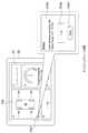
以下、本発明の実施形態を図面に基づいて説明する。図1は、本発明に係る車載伝送装置とモバイル端末及びこれらを含む積載荷重情報表示システムの構成を示すブロック図である。
図1に示すように、本実施形態の積載荷重情報表示システム1は、車両11に搭載される車載伝送装置10と、運転者が携帯可能なモバイル端末20とから構成される。ここでのモバイル端末とは、具体的には、Bluetooth(登録商標、以下、省略)技術等の近距離間の無線通信(伝送)手段30を備えるスマートフォンやタブレットの携帯端末を示す。
なお、本発明は本実施形態に限定解釈されるものではなく本発明の範囲内において適宜設計変更可能である。Hereinafter, embodiments of the present invention will be described with reference to the drawings. FIG. 1 is a block diagram showing a configuration of an in-vehicle transmission device and a mobile terminal according to the present invention and a load-bearing information display system including these.
As shown in FIG. 1, the load-bearing information display system 1 of the present embodiment includes an in-
The present invention is not limited to the present embodiment, and the design can be appropriately changed within the scope of the present invention.
[車載伝送装置]
車載伝送装置10は、センサ信号収集部14と、車載制御部16と、モバイル端末20との通信を行う車載通信部15と、図示しない電源部を備えている。また、この車載伝送装置10の車両11での取付場所は、モバイル端末20との無線通信手段30の通信環境を良好とするため、モバイル端末20を携帯する運転者が荷物の乗り降ろしを行なう車両後部側のスライドドアやハッチバックドア近傍の車内に備えられることが好ましい。車載制御部16は、CPU(中央処理装置)やメモリを備えている。
なお、図示しない電源部は、車両積載のバッテリーで、車載伝送装置10の各部動作のために電源を供給するものである。[In-vehicle transmission device]
The vehicle-mounted
The power supply unit (not shown) is a battery loaded on the vehicle and supplies power for the operation of each unit of the in-
センサ信号収集部14は、例えば、小型商用車等の車両11の前後左右の車輪12のサスペンションに備えられた4つの積載荷重センサ13、13、13、13の圧力センサ13a、13a、13a、13a(図2)と接続され、車両重量及び積載重量のセンサ信号を収集する機能を有している。 The sensor
圧力センサ13aの一例を示すと、例えば図2には前輪側に備えられる積載荷重センサ13の一部が示されており、圧力センサ13aは円柱状に形成され、取付部13bの下面13cに設けられているセンサ連結部13dに連結されている。また、取付部13bには、懸架装置のアーム側に締結固定するためのボルトを挿通させる複数個のボルト挿通孔13eを備えている。 As an example of the
本実施形態の積載荷重センサ13は油圧式で、図2に示すようにスプリング荷重Pを受けると積載荷重センサ13に備えられているダイアフラムが柔軟に変形し、油圧室の圧力が上昇し、この圧力変化から積載荷重を計測できる。そして、圧力を測定した後、当該圧力を電圧(電気)のセンサ信号に変換して、変換されたセンサ信号は配線13fを介してセンサ信号収集部14にて収集される。
なお、本発明にて想定される積載荷重センサ13の圧力センサ13aは周知構造のものが適宜本発明の範囲内において選択使用されるものであり、特に限定解釈はされず、本発明の範囲内で最適なものが適宜選択可能である。The load-bearing
As the
なお、センサ信号収集部14のセンサ信号の収集機能は、車両11のエンジン始動前にモバイル端末20からの要求によって開始してもよいし、また、センサ信号収集部14のセンサ信号の収集機能は、運転者の手動により車両11のエンジン始動に連動して車載伝送装置10の動作がオンになることにより開始してもよい。また、エンジン始動前から車両11への積載作業を始めることがあることを想定して、エンジン始動されていなくても積載荷重センサ13が積載を感知したら車載伝送装置10の各部機能(センサ信号収集部14のセンサ信号の収集機能を含む)を自動的にオンとしてもよい。ここでのセンサ信号のサンプリングレートは、例えば、7Hzに調整されている。 The sensor signal collecting function of the sensor
車載制御部16は、車載伝送装置10の各部機能動作を制御するもので、例えばセンサ信号収集部14のセンサ信号収集や車載通信部15の通信を制御する。
また、車載制御部16の機能として、各部動作を制御する他に、これらの制御情報やセンサ信号収集部14の電圧(電気)のセンサ信号をCPUに接続されたメモリに蓄えて車載通信部15に受け渡すことができる。これらのセンサ情報を記憶するには、ハードディスク、半導体メモリ等を用いてもよい。The in-
Further, as a function of the vehicle-mounted
車載通信部15は、モバイル端末20との無線通信30を行うためのインタフェース手段で、センサ信号収集部14からのセンサ信号収集結果を受け渡される。
また、本実施形態では、車載通信部15の無線通信手段にBluetooth技術を使用するが、特に限定されることはなく、公知の通信手段を用いることができる。The in-
Further, in the present embodiment, Bluetooth technology is used as the wireless communication means of the vehicle-mounted
Bluetoothの場合、まず始めに、車載通信部15側がペアリングモードで近距離の待ち受け状態において、モバイル端末20の電源がONとなり、本実施形態に係るアプリケーションソフト(以下、単にアプリソフトという。)が運転者によって起動されるに伴い、モバイル端末20のペアリング要求に呼応して自動的にペアリングを行い、相互に無線通信30の接続を完成する。
Bluetoothは、デジタル機器用の近距離無線通信規格の1つで、モバイル端末20の既存の機能を用いることで、モバイル端末に新たな回路等を追加することなく、本実施形態の構成を実現できる。
なお、このBluetooth技術に限定されることはなく、WiFi近距離通信(NFC)、セルラーネットワーク、又は任意の他の無線又はRF接続による、任意のモバイル通信方法を使うこともできる。In the case of Bluetooth, first, the
Bluetooth is one of the short-range wireless communication standards for digital devices, and by using the existing functions of the
It should be noted that the Bluetooth technology is not limited, and any mobile communication method by WiFi Near Field Communication (NFC), cellular network, or any other wireless or RF connection can be used.
以上、説明のとおり、本実施形態の車載伝送装置10は、各車輪12の積載荷重センサ13のセンサ信号をBluetooth等の近距離通信手段を介して、スマートフォンやタブレットなどのモバイル端末20に送ることができ、従来技術での車載ECUが不要で、ワイヤーシステムも不要となる効果が得られる。 As described above, the vehicle-mounted
[モバイル端末]
モバイル端末20は、車載伝送装置10の車載通信部15と通信を行うモバイル通信部21と、モバイル通信部21から受け渡されたセンサ信号による車両重量及び各車輪の荷重を合計した積載重量情報に基づき積載偏度を計算処理する演算処理部22と、車両重量と積載重量及び演算処理部22で導き出された積載偏度の情報を画面表示する表示部23と、表示部23の画面制御等を行なうモバイル制御部25と、車両諸元の数値を演算処理部22にデータ入力する操作、サンプリングレート調整の操作、画面表示レイアウト操作等を行う入力操作部24と、複数の表示画面レイアウトや車両諸元の数値や積載状況運行記録(時間的に記録する電子的タコグラフ)等を記憶しておく記憶部26と、を備えている。
なお、図示していないが、モバイル端末20は、積載重量情報の警告音を発する機能も有しているが、運転者を警告音で驚かさないように、アプリソフトの初期設定では警告音のスピーカをオフにして鳴らないように設定している。[mobile computer]
The
Although not shown, the
また、モバイル端末20は、具体的にはスマートフォンやタブレット等のモバイル端末であって、モバイル端末20にアプリソフトがインストール(実装)される。これにより、随時アプリソフトを更新していくことで、車両情報やプログラム演算式の更新が容易に行われ得る。 Further, the
モバイル通信部21は、車載通信部15と対向して無線通信を行うもので、モバイル端末20に備えられたBluetooth技術の通信手段を用いて無線通信を行なう。この通信手段の説明については、前述の車載通信部15で説明した内容と重複するので省略するが、特に限定されることはなく、公知の通信手段を用いることができる。 The
演算処理部22は、モバイル端末20に演算(計算)式がインストール(実装)されていて、センサ計測された前後左右の各車輪12の積載荷重から積載偏度、具体的には、重量配分計算、空車時の重心位置、積載時の重心位置を演算することができる。以下、演算処理部22の演算について、説明する。 The
図3(b)は、上記演算に必要な車両諸元を示している。これらの車両諸元の数値は、車両の車種と対応付けられた車両諸元を初期設定での入力操作により記憶部26に記録させておく。これにより、運転者がアプリソフト起動時に入力操作部24から入力した車種等の選択により、該当する車種対応の車両諸元を自動的に読み出し、空車時の重心位置及び積載時の重心位置の演算に供することができる。なお、運転者がアプリソフト起動時の都度、入力操作部24から車両諸元の数値データを直接入力し、演算させるようにしておいても構わない。 FIG. 3B shows the vehicle specifications required for the above calculation. The numerical values of these vehicle specifications are recorded in the
以下に記載する車両諸元において、図3(b)に示すように、ホイールベースとは、車輪12の前輪軸と後輪軸との距離を表し、フロントトレッド及びリアトレッドとは車両11の左右の車輪12の中心間距離(輪距)をいい、単位はいずれもmmで表す。
[演算式での換算に必要な車両諸元]
Lはホイールベースを表す。
Tfはフロントトレッドを表す。
Trはリアトレッドを表す。In the vehicle specifications described below, as shown in FIG. 3B, the wheelbase represents the distance between the front wheel axle and the rear wheel axle of the
[Vehicle specifications required for conversion using arithmetic formulas]
L represents the wheelbase.
Tf represents the front tread.
Tr represents the rear tread.
次に、前後左右の4つの車輪12、12、12、12の積載荷重センサ13、13、13、13で計測する個々の重量の合算は、式(1)に示すとおり車両積載重量W(kg)となる。ここで、前後左右の各車輪12の積載重量を図3に示すとおり、表示画面23aにて、運転者が視認できる。 Next, the sum of the individual weights measured by the

また、式(1)を用いて、図3(a)の表示画面23dに示すとおり、積載荷重△Wである空車時車両重量Woと積載時車両重量Wnの差分を分子に示し、最大積載重量を分母に示すことで積載状態が数値にて具体的に視認できる。なお、最大積載重量は車両毎に設定することができる。 Further, using the formula (1), as shown in the
次に、各質量(重量)合計の定義は式(2)のとおりである。式(2)では、車輪12の前輪の荷重の合算がWfront(kg)、後輪の荷重の合算がWrear(kg)、左輪の荷重の合算がWleft(kg)、右輪の荷重の合算がWright(kg)で示されている。
Wfront:前輪積載合計荷重[kg]
Wrear:後輪積載合計荷重[kg]
Wleft:左輪積載合計荷重[kg]
Wright:右輪積載合計荷重[kg]Next, the definition of each mass (weight) total is as shown in equation (2). In the formula (2), the total load of the front wheels of the
Wfront : Total load on front wheels [kg]
Wrear : Total load on rear wheels [kg]
Wleft : Total load on the left wheel [kg]
Wright : Total load on the right wheel [kg]
次に車両の前後輪及び左右輪の重量配分計算式は式(3)のとおりである。
車両重量W(kg)を分母とし、前後輪側の前後重量配分(%)と左右輪側の左右重量配分(%)をそれぞれ示す。Next, the weight distribution calculation formula for the front and rear wheels and the left and right wheels of the vehicle is as shown in equation (3).
The vehicle weight W (kg) is used as the denominator, and the front-rear weight distribution (%) on the front-rear wheel side and the left-right weight distribution (%) on the left-right wheel side are shown.
次に積載していない空車時の重心位置の計算式は式(4)と式(5)のとおりである。ここでのxとyは、図3(a)の表示画面Aに示すポインタGの座標を示す。 Next, the formulas for calculating the position of the center of gravity when the vehicle is not loaded are as shown in formulas (4) and (5). Here, x and y indicate the coordinates of the pointer G shown on the display screen A in FIG. 3A.
次に積載時の重心位置の計算式は式(6)と式(7)のとおりである。
ここでのxとyは、図3(a)の表示画面Aに示すポインタGの座標を示す。Next, the formulas for calculating the position of the center of gravity at the time of loading are as shown in formulas (6) and (7).
Here, x and y indicate the coordinates of the pointer G shown on the display screen A in FIG. 3A.
上記の数式の演算は、この高速のセンサ信号のサンプリングレート調整による所定間隔(例えば、7Hz)で車両重量・積載重量が演算処理部22に入力され高速に演算処理されるため、従来技術での課題であった荷重センサ出力オフセット調整値、特性補正値及びゲイン値等の補正処理が必要でなくなる。
このように高速処理されるため、表示画面が常時リアルタイムに連続して更新され、運転者は即座に前後左右の各車輪の積載荷重から積載偏度を把握することができる。In the calculation of the above mathematical formula, the vehicle weight and the loaded weight are input to the
Since the high-speed processing is performed in this way, the display screen is constantly and continuously updated in real time, and the driver can immediately grasp the load skewness from the load load of each of the front, rear, left, and right wheels.
さらに、従来、各車輪近傍に車載された歪ゲージや磁歪式センサ等からの荷重出力信号に対し、荷重センサ出力オフセット調整値、特性補正値、ゲイン値等の各テーブル及び重量換算式等について前もって車両に格納されたマイクロコンピュータで計算処理されていたが、これらの複雑な処理が不要となるため車両側のマイクロコンピュータも不要となる。 Further, conventionally, with respect to the load output signal from the strain gauge or the magnetic strain type sensor mounted on the vehicle near each wheel, each table such as the load sensor output offset adjustment value, the characteristic correction value, the gain value, and the weight conversion formula are prepared in advance. The calculation process was performed by the microcomputer stored in the vehicle, but since these complicated processes are not required, the computer on the vehicle side is also unnecessary.
なお、演算処理部22での演算は、モバイル端末20に備えられたCPUを使うことができるが、それぞれの演算処理ごとに演算処理装置があって構わない。 Although the CPU provided in the
モバイル制御部25は、モバイル端末20に備えられたCPUによって表示部23を制御して、モバイル通信部21からの車両積載重量、各車輪の積載重量や演算で導き出された積載偏度の積載荷重情報を一つの表示画面上に同時に表示するように指示を出す。例えば、図3(a)に示すように、表示画面23aにA:各車輪毎の積載荷重と重心位置を表示(図示しないが、各輪の総重量表示も可)、表示画面23bにB:車両総重量、表示画面23cにC:モデル型式、車台番号、車両諸元等テキスト情報、表示画面23dにD:最大積載重量に対する積載重量を表示、表示画面23eにE:積載ステータス(Good/Warning/Overloadの3段階のいずれかを表示)の複数の表示画面を同一の表示画面23内に表示させる。
このように、モバイル端末20は、空車或いは積載時の車両における積載荷重情報を、表示部23の同一画面上に同時に表示でき、運転者は視線を移動させることなく即座に積載荷重情報を視認することができる。よって、本実施形態は運転者にとってユーザーフレンドリーなインタフェースといえる。The
In this way, the
以上説明のとおり、モバイル制御部25からの表示指示により記憶部26から所定の表示画面(領域、レイアウト)を読み出し、当該表示指示にしたがって、複数の積載荷重情報A〜Eを表示画面23a〜23eに表示させるように制御する。 As described above, a predetermined display screen (area, layout) is read from the
なお、モバイル端末20の画面サイズがスマートフォン端末のように小さい場合には、モバイル制御部25は、A:各車輪の荷重と重心位置を表示、B:車両積載重量、C:モデル型式、車台番号、車両諸元等テキスト情報、D:最大積載重量に対する積載重量を表示、E:積載ステータス(Good/Warning/Overloadの3段階)のうちのいずれか一つを表示するように画面偏移制御することができる。
また、これらの画面偏移表示は、運転者に優先的な表示画面を選択し、見易く制御することが可能である。When the screen size of the
In addition, these screen shift displays can be controlled in an easy-to-see manner by selecting a display screen that is prioritized by the driver.
表示部23は、センサ信号からの車両重量と積載重量及び演算処理部22での演算で導き出された積載偏度等の情報を、画面領域別に分けて画面表示するものである。表示部23は、スマートフォンやタブレットのモバイル端末に備えられた液晶ディスプレイ等の公知の表示手段を用いることができる。本実施形態の説明は、画面表示サイズが大きいタブレットを想定して行なう。
また、表示部23の表示画面のタッチパネル機能により、入力操作部24の入力操作画面を表示部23に表示する。この機能については、入力操作部24の事項で説明する。The
Further, the input operation screen of the
また、乗車中や降車中に関係なく、車両11の車外からも、モバイル端末20での車両積載情報を表示部23で視認できる。走行安全を考慮すると、走行中はモバイル端末20を車載ナビゲーション装置の表示画面に無線或いは有線で接続して、車両積載情報を車載ナビゲーション装置の表示画面に表示することが望ましい。すなわち、車載ナビゲーション装置の表示画面を用いることができれば、運転者だけでなく助手席の同乗者も積載偏度等を視認することができ、より安全性が増すことになる。 In addition, the vehicle loading information on the
[表示画面の役割]
先ず、表示部23の表示画面23a〜23eの役割を説明する。本実施形態では、表示画面23a〜23bは一画面の領域左側に、表示画面23c〜23eは一画面の領域右側にそれぞれ配置表示されるが、この画面レイアウトに限定されることも無く、その組合せや配置が変更されても本発明の実施範囲内である。また、表示画面23a、23d、23eが、過積載、危険偏荷重、荷崩れ、荷物の移動が発生した際に警告表示を行う表示領域となっており、特に表示画面23a、23dは、表示内容を運転者に強調できるよう他の表示領域よりも大きい。[Role of display screen]
First, the roles of the display screens 23a to 23e of the
表示部23の左側上の略正方形の領域である表示画面23aには、A:各車輪毎の荷重と重心位置(各輪の総重量表示も可)を表示させている。具体的には、表示画面23a内に車両の前後左右4つの車輪を図示し、その各車両の積載荷重センサ13、13、13、13で計測された4つの車輪12、12、12、12の荷重は、数字(図中の「(Wfl)kg、(Wfr)kg、(Wrl)kg、(Wrr)kg」)で表示されている。また、表示画面23aにより区画される左上の略正方形の領域Aは、他の情報表示領域B、C、D、Eより大きくして、運転者に認識し易くしている。
このように、単なる数字の表示だけでなく、数字を車両11と車輪12のイラストと一体にして表示することで、運転者に直感的に認識され易くユーザーフレンドリーになるようにしている。On the
In this way, not only the display of the numbers but also the numbers are displayed integrally with the illustrations of the
また、表示画面23aには、その車両図内に重心位置Gが、演算処理部22での演算で導き出された積載偏度の情報を示す表示として、模式的に画面表示されている。図5は、その積載偏度の表示例である。記号「G」はポインタを表し、ポインタ「G」が各車輪の積載重量に応じてxy移動することで積載偏度の変化をグラフィカルに表示している。この記号「G」は、「Center of Gravity(重心)」のGの文字をあてたものである。 Further, on the
表示画面23aの一部拡大図を示す図4において、積載荷重のバランスが理想的である状態の場合、ポインタ「G」は車両11の中心位置にある。ポインタ「G」は、車両11に荷物が積載されていくに連れて、各車輪12の積載荷重から積載偏度が計算された結果(式(6)と(7)を参照。xyはポインタGの座標)に基づき、モバイル制御部25の指示により画面内の積載荷重に応じた位置に移動する。 In FIG. 4, which shows a partially enlarged view of the
表示画面23a内のポインタ「G」の移動結果は、積載偏度に応じて決まる位置(移動後の位置)に基づいて、3段階に区分けされる。3段階の区分けは、移動結果が車両中心の重心位置に近い場合は「偏度(小)、Good(図4では薄い網掛領域)」、車両中心の重心位置から少しずれ片寄りがある場合は「偏度(中)、Warning(図4では少し濃い網掛領域)」、さらにずれ片寄りがある場合は「偏度(大)、Danger(図4では最も濃い網掛領域)」という区分けである。つまり、積載ステータス(Good/Warning/Overload)は3段階で区分けされる。ポインタ「G」の示す位置を上下左右(図4では矢印)、xy方向に積載重量に応じて移動表示することによって、何処の車両積載位置に問題があるか運転者は瞬時に理解できる。
このように表示することで、運転者に積載ステータスを直感的に認識し易くし、ユーザーフレンドリーになるようにしている。The movement result of the pointer "G" in the
By displaying in this way, it is easy for the driver to intuitively recognize the loading status and it is made user-friendly.
また、表示部23の左側下の略正方形の領域である表示画面23bには、B:車両積載重量を表示させている。これによって、車両の合計した積載重量情報を同時に取得し確認できる。 Further, B: vehicle load weight is displayed on the
表示部23における表示領域の右上側にある表示画面23cには、C:モデル型式、車台番号、車両諸元等テキスト情報を表示させている。これによって、車両の一般的情報をも同時に取得し確認できる。 Text information such as C: model model, chassis number, and vehicle specifications is displayed on the
表示部23における表示領域の右中側にある表示画面23dには、D:最大積載重量に対する積載重量を表示させている。具体的には、ポインタ「G」の移動で積載偏度を確認する他に、表示画面23dに示すように、車両積載重量情報の積載ステータスを指針式の計器画像によるアナログ化で表示し、積載荷重表示を数値によるデジタル化で表示して同一画面内に同時表示している。
すなわち、積載ステータスを指針式の計器画像23d1、23d2により画像表示し、かつ、積載重量を数字画像によるデジタル積載重量表示計23d3により画像表示することで、同一表示画面23d内の上下に同時にアナログ画像表示とデジタル(数字)の積載荷重表示を行なうようにしている。このように、表示画面23dには、指針23d2の表示が積載ステータスの3段階の計器画像23d1に示され、かつ、デジタル積載重量表示計23d3を混在させて同時に表示している。On the
That is, by displaying the loading status as an image by the pointer-type instrument images 23d1 and 23d2 and displaying the loading weight as an image by the digital loading weight display meter 23d3 using a numerical image, analog images are simultaneously displayed above and below the
これにより、アナログ画像表示の指針式計器にデジタル(数字)を同一表示画面上に組み合わせて読み取り精度をあげ分かり易くすることで、運転者が積載状況を的確に確認することが可能となる。つまり、運転者に対してユーザーフレンドリーなマンマシンインタフェースを実現させている。
また、例えば、走行中に荷物の落下などの発生によって積載偏度や積載重量が変化したことを視覚的かつ的確に把握させることができる。
このように車両11の積載状況を多角的に表示することで、運転者が指針位置から積載ステータスを直感的に把握するとともにデジタル積載重量表示計で積載状況を的確に確認することが可能となる。As a result, the driver can accurately check the loading status by combining a pointer-type instrument for displaying an analog image with digital (numbers) on the same display screen to improve reading accuracy and make it easier to understand. In other words, it realizes a user-friendly man-machine interface for the driver.
Further, for example, it is possible to visually and accurately grasp that the load skewness and the load weight have changed due to the occurrence of a load falling during traveling.
By displaying the loading status of the
表示部23における表示領域の右下側にある表示画面23eには、E:積載ステータス(Good/Warning/Overloadの3段階)を積載ステータスに応じた背景色(表示画面23eの表示領域をGoodは緑色(または青色)/Warningは黄色/Overloadは赤色、図では無色)に、Good/Warning/Overloadの各文字を黒色で表示させている。
具体的には、例えば、図5(a)の表示画面23eに示すところの積載ステータス「Good」は、アナログメータの指針23d2が緑色ゾーン(図面では無色)の範囲で、図5(b)の表示画面23eに示すところの積載ステータス「Warning」は、アナログメータの指針23d2が黄色ゾーン(図面では無色)の範囲で、図5(c)の表示画面23eに示すところの積載ステータス「Overload」は、アナログメータ指針が赤色ゾーン(図面では網掛け)の範囲である。また、表示画面23dにおいては、積載ステータスの計器画像の下の領域23d3(図3(a))に、総積載荷重(分母)に対する積載重量(分子)をデジタル表示している。On the
Specifically, for example, the loading status “Good” shown on the
このように、積載の状態を示すアナログメータの指針23d2を表示する(アナログ表示)と共に、当該指針23d2の下の領域23d3に総積載荷重(分母)に対する積載重量(分子)をデジタル表示で表示している。つまり、アナログ表示とデジタル表示という異なる切り口で2種類の表示を組み合わせ一体的に同一画面領域に表示させることで、運転者が積載荷重の状態を対比判読できる。
特に積載偏度をフルカラー(例えば緑色、黄色、赤色の三色)で、かつグラフィカルに表示することによって、運転者は積載に問題あるか否かの有無を容易に判断し、現在の車両の積載状況を把握することができることになる。
また、積載ステータス「Overload」の範囲に至った場合、「Overload」の画面表示を点滅させて警告することもでき、警告音に代わって運転者に視覚的に注意喚起を促すことも可能である。例えば、積載ステータス「Good」の範囲では無音で、積載ステータス「Warning」の範囲では長い間隔に連続音で、積載ステータス「Overload」の範囲では短い間隔の連続音で、運手者等に警告することができる。また、併せて警告音がオンであれば、音量も次第に大きくできる。
このように多角的に表示させることで、運転者に分かり易く警告されることになるユーザーフレンドリーなマンマシンインタフェースが実現している。In this way, the pointer 23d2 of the analog meter indicating the loading status is displayed (analog display), and the load weight (numerator) with respect to the total load (denominator) is digitally displayed in the area 23d3 below the pointer 23d2. ing. That is, by combining two types of displays from different perspectives of analog display and digital display and displaying them integrally on the same screen area, the driver can compare and read the state of the loaded load.
In particular, by displaying the loading skewness in full color (for example, three colors of green, yellow, and red) and graphically, the driver can easily determine whether or not there is a problem with loading, and the current vehicle is loaded. You will be able to grasp the situation.
In addition, when the loading status reaches the range of "Overload", the screen display of "Overload" can be flashed to warn the driver, and the driver can be visually alerted instead of the warning sound. .. For example, there is no sound in the range of the loading status "Good", a continuous sound at long intervals in the range of the loading status "Warning", and a continuous sound at short intervals in the range of the loading status "Overload" to warn the carrier and the like. be able to. Also, if the warning sound is on, the volume can be gradually increased.
By displaying from multiple angles in this way, a user-friendly man-machine interface that gives the driver an easy-to-understand warning is realized.
[積載荷重に応じた画面表示]
次に積載荷重に応じた状態偏移の表示画面23a〜23eの表示事例について、図5と図6を用いて詳細に説明する。ここでの事例では、最大積載重量が800kgで、車両重量が2000kgfである車両を想定する。車両積載荷重が200kgfの車両を図5(a)と図6(a)に示し、車両積載荷重が600kgfの車両を図5(b)と図6(b)に示し、車両積載荷重が1000kgfの車両を図5(c)と図6(c)に示す。なお、説明上、図において、重心位置のポインタGについては説明をしないので、同じ位置のままとしている。[Screen display according to load]
Next, a display example of the state
車両が200kgfの荷重を積載している場合(以下、この場合を「200kgf積載車の場合」という)、図5(a)に示すように、表示画面23aにおいて、車両の積載荷重センサ13、13、13、13で計測された4つの車輪12、12、12、12の荷重が50kg(Wfl)、50kg(Wfr)、50kg(Wrl)、50kg(Wrr)であることが表示されている。そして、図6(a)に示すように、表示画面23dにおいて、式(1)に基づく演算の結果、各車輪積載荷重(Wfl)kg、(Wfr)kg(Wrl)kg、(Wrr)kgの合計である積載重量200kgを分子に示し、最大積載重量800kgを分母に示すことで積載状態が数値にて具体的に視認できる。
そして、図6(a)に示すように、アナログメータ指針23d2が緑色ゾーン(図面では無色)の範囲を指し示している。したがって、図6(a)に示すように、表示画面23eにおいて、積載ステータス「Good」が緑色背景色(図では無色)に黒文字で点灯表示される。この点灯表示により、運転者は、安全範囲であることを認識できる。
また、200kgf積載車の場合、図5(a)に示すように、表示画面23bにおいて、車両積載重量200kgと車両重量2000kgとを合算した車両総重量2200kgが表示されている。When the vehicle is loaded with a load of 200 kgf (hereinafter, this case is referred to as "the case of a vehicle loaded with 200 kgf"), as shown in FIG. 5 (a), the
Then, as shown in FIG. 6A, the analog meter pointer 23d2 points to the range of the green zone (colorless in the drawing). Therefore, as shown in FIG. 6A, the loading status “Good” is lit and displayed in black characters on the green background color (colorless in the figure) on the
Further, in the case of a 200 kgf loaded vehicle, as shown in FIG. 5A, the total vehicle weight of 2200 kg, which is the sum of the vehicle loaded weight of 200 kg and the vehicle weight of 2000 kg, is displayed on the
車両が600kgfの荷重を積載している場合(以下、この場合を「600kgf積載車の場合」という)、図5(b)に示すように、表示画面23aにおいて、車両の積載荷重センサ13、13、13、13で計測された4つの車輪12、12、12、12の荷重が100kg(Wfl)、100kg(Wfr)、200kg(Wrl)、200kg(Wrr)であることが表示されている。そして、図6(b)に示すように、表示画面23dにおいて、式(1)に基づく演算の結果、車両積載重量(Wfl)kg、(Wfr)kg、(Wrl)kg、(Wrr)kgの合計である積載重量600kgを分子に示し、最大積載重量800kgを分母に示すことで積載状態が数値にて具体的に視認できる。
そして、図6(b)に示すように、アナログメータ指針23d2が黄色ゾーン(図面では無色)の範囲を指し示している。したがって、図6(b)の表示画面23eにおいて、積載ステータス「Warning」が黄色背景色(図では無色)に黒文字で点灯表示される。この点灯表示により、運転者は、安全範囲を超えて注意範囲であることを認識できる。
また、600kgf積載車の場合、図5(b)に示すように、表示画面23bにおいて、積載重量600kgと車両重量2000kgとを合算した総重量2600kgが表示されている。When the vehicle is loaded with a load of 600 kgf (hereinafter, this case is referred to as "in the case of a vehicle loaded with 600 kgf"), as shown in FIG. 5 (b), the
Then, as shown in FIG. 6B, the analog meter pointer 23d2 points to the range of the yellow zone (colorless in the drawing). Therefore, on the
Further, in the case of a 600 kgf loaded vehicle, as shown in FIG. 5B, a total weight of 2600 kg, which is the sum of the loaded weight of 600 kg and the vehicle weight of 2000 kg, is displayed on the
車両が1000kgfの荷重を積載している場合(以下、この場合を「1000kgf積載車の場合」という)、図5(c)に示すように、表示画面23aにおいて、車両の積載荷重センサ13、13、13、13で計測された4つの車輪12、12、12、12の荷重が150kg(Wfl)、150kg(Wfr)、350kg(Wrl)、350kg(Wrr)であることが表示されている。そして、図6(c)に示すように、表示画面23dにおいて、式(1)に基づく演算の結果、車両積載重量(Wfl)kg、(Wfr)kg、(Wrl)kg、(Wrr)kgの合計である積載重量1000kgを分子に示し、最大積載重量800kgを分母に示すことで積載状態が数値にて過積載であることが具体的に視認できる。 When the vehicle is loaded with a load of 1000 kgf (hereinafter, this case is referred to as "in the case of a vehicle loaded with 1000 kgf"), as shown in FIG. 5 (c), the
そして、図6(c)に示すように、アナログメータ指針23d2が赤色ゾーン(図面では無色)の範囲を指し示している。したがって、図6(c)の表示画面23eにおいて、積載ステータス「Overload」が赤色背景色(図では無色)に黒文字で点灯表示される。この点灯表示により、運転者は、過積載状態にて危険であることを認識できる。
また、1000kgf積載車の場合、図5(c)に示すように、表示画面23bにおいて、積載重量1000kgと車両重量2000kgとを合算した総重量3000kgが表示されている。Then, as shown in FIG. 6C, the analog meter pointer 23d2 points to the range of the red zone (colorless in the drawing). Therefore, on the
Further, in the case of a 1000 kgf loaded vehicle, as shown in FIG. 5 (c), a total weight of 3000 kg, which is the sum of the loaded weight of 1000 kg and the vehicle weight of 2000 kg, is displayed on the
したがって、積載重量の積載状態が、表示部23a、23d、23eによって視覚的かつ的確に表示されるので、運転者に容易に荷物の積載状態を把握させることができる。 Therefore, since the loaded state of the loaded weight is visually and accurately displayed by the
[重心位置移動に応じた画面表示]
次に、図7(a)、図7(b)、図7(c)、図7(d)および図7(e)を参照して、重心位置の移動に応じたポインタGの表示例について説明する。ポインタGの位置は、図4に示されているとおり、積載重量に応じて上下左右、xy方向に移動する。ここで、図面の上下が車両前後で、図面の左右が車両左右である。
本実施形態では、図7(a)は重心位置(ポインタG)が車両11の前方(上側)にある場合を示し、図7(b)は重心位置(ポインタG)が車両11の中心にある場合を示し、図7(c)は重心位置(ポインタG)が車両11の後方(下側)にある場合を示し、図7(d)は重心位置(ポインタG)が車両11の左方にある場合を示し、図7(e)は重心位置(ポインタG)が車両11の右方にある場合を示している。以下、図7(a)〜図7(e)に示した5つのパターンについて説明する。[Screen display according to the movement of the center of gravity]
Next, with reference to FIGS. 7 (a), 7 (b), 7 (c), 7 (d), and 7 (e), a display example of the pointer G according to the movement of the center of gravity position will be provided. explain. As shown in FIG. 4, the position of the pointer G moves up, down, left, right, and in the xy direction according to the load weight. Here, the top and bottom of the drawing are the front and rear of the vehicle, and the left and right of the drawing are the left and right of the vehicle.
In the present embodiment, FIG. 7A shows the case where the center of gravity position (pointer G) is in front (upper side) of the
図7(a)は、表示画面23aにおいて、重心位置(ポインタG)が車両11の前方(上側)にあるパターンである。表示画面23aにおいて、車両の積載荷重センサ13、13、13、13で計測された4つの車輪12、12、12、12の荷重が600kg(Wfl)、600kg(Wfr)、400kg(Wrl)、400kg(Wrr)であり、Front/rear Weight ratio(前後重量比率)が60対40である場合、画面表示部23aの車両の模式図の前方に重心位置表示のポインタGが表示されている。 FIG. 7A is a pattern in which the center of gravity position (pointer G) is in front (upper side) of the
図7(b)に示すように、表示画面23aでは、車両の積載荷重センサ13、13、13、13で計測された4つの車輪12、12、12、12の荷重が625kg(Wfl)、625kg(Wfr)、625kg(Wrl)、625kg(Wrr)であり、Front/rear Weight ratio(前後重量比率)が50対50の均等である場合、画面表示部23aの車両の模式図の中央部に重心位置表示のポインタGが表示されている。 As shown in FIG. 7B, on the
図7(c)に示すように、表示画面23aでは、車両の積載荷重センサ13、13、13、13で計測された4つの車輪12、12、12、12の荷重が600kg(Wfl)、600kg(Wfr)、900kg(Wrl)、900kg(Wrr)であり、Front/rear Weight ratio(前後重量比率)が40対60である場合、画面表示部23aの車両の模式図の後方に重心位置表示のポインタGが表示されている。 As shown in FIG. 7C, on the
図7(d)に示すように、表示画面23aでは、車両の積載荷重センサ13、13、13、13で計測された4つの車輪12、12、12、12の荷重が725kg(Wfl)、525kg(Wfr)、725kg(Wrl)、525kg(Wrr)であり、Left/right Weight ratio(左右重量比率)が60対40である場合、画面表示部23aの車両の模式図の左方に重心位置表示のポインタGが表示されている。 As shown in FIG. 7D, on the
図7(e)に示すように、表示画面23aでは、車両の積載荷重センサ13、13、13、13で計測された4つの車輪12、12、12、12の荷重が525kg(Wfl)、725kg(Wfr)、525kg(Wrl)、725kg(Wrr)であり、Left/right Weight ratio(左右重量比率)が40対60である場合、画面表示部23aの車両の模式図の右方に重心位置表示のポインタGが表示されている。 As shown in FIG. 7 (e), on the
このように、ポインタ「G」の示す位置を画面表示することによって、何処の車両積載位置に危険があるかを、運転者が瞬時に且つ直感的に認識し易くしており、ユーザーフレンドリーになるようにしている。
そして、危険な積載偏度が発生しているか否かを、図4に示した、偏差の大中小の範囲のポインタGの表示位置によって、表示画面23aに視覚的かつ的確に表示できるので、運転者は容易に荷物の積載状態を把握することができる。また、走行前に重心位置が危険な位置に偏っている場合は、運転者は、ポインタGの表示位置に基づいて走行開始前に荷崩れ発生となる積載状態を修正できる。By displaying the position indicated by the pointer "G" on the screen in this way, it is easy for the driver to instantly and intuitively recognize where the vehicle loading position is dangerous, and it becomes user-friendly. I am trying to do it.
Then, whether or not a dangerous loading skewness has occurred can be visually and accurately displayed on the
また、走行開始後に積載偏度の変化が発生すれば、運転者に荷物の落下や移動等があったことを視覚的かつ的確に把握させることができる。よって、走行中の事故を防止することが可能となり、安全性を向上させることができる。 Further, if the load skewness changes after the start of traveling, the driver can visually and accurately grasp that the luggage has fallen or moved. Therefore, it is possible to prevent accidents during traveling and improve safety.
以上の説明のとおり、本実施形態では、過積載を警報するだけではなく、積載重量を高速レートにてセンサで計測し、計測値を車載通信部15から無線通信手段30及びモバイル通信部21を介して演算処理部22に送信して演算処理する。そして、当該演算処理により得られる積載偏度を含め総合的な荷重積載情報をモバイル端末20にリアルタイムに表示することで過積載を確実に防止できる。
また、過積載によって発生確率の高まる交通事故を未然に防ぎ、安全性能を向上させることができると共に、4輪車両の荷重情報を変速機やブレーキの制御に利用することもできる。As described above, in the present embodiment, not only the overload is warned, but also the load weight is measured by the sensor at a high speed rate, and the measured values are measured from the in-
In addition, it is possible to prevent traffic accidents, which are likely to occur due to overloading, to improve safety performance, and it is also possible to use load information of a four-wheeled vehicle for controlling a transmission and a brake.
入力操作部24は、モバイル端末20の表示部23の表示画面のタッチパネルを入力表示手段としており、車両諸元の数値、センサ信号のサンプリングレート調整、警告音有無、表示画面の切り替え、画面表示レイアウト等の初期設定入力、積載状況運行記録のデータ表示、表示画面偏移の操作等を行うことができる。なお、タッチパネル機能は、公知の入力手段を用いることができる。 The
例えば、表示部23の表示画面のタッチパネルによる一例(Setting:Load sending sampling rate)を、図8に示す。表示画面Aの左下欄に矢印記号23a1の表示があり、矢印符号23a1を押す(Push)と、センサ信号のサンプリングレート調整の範囲を決定する画面に移行する。入力範囲(input range)は0.5Hzから10Hzまでであり、本実施形態では所定数値として7Hzをセットし(符号23a2)、「allow」表示23a3を押せばサンプリングレートが7Hzで行われる。 For example, FIG. 8 shows an example (Setting: Load sending sampling rate) of the display screen of the
モバイル端末20の記憶部26は、モバイル制御部25の指示により、車両諸元の数値の他、積載状況運行記録(電子的タコグラフ)等として、前後左右の各車輪12の車両積載重量W(kg)、重量配分計算(%)、空車時の重心位置、積載時の重心位置が随時リアルタイムに再演算実行された結果の記憶と、これら結果を表示部23の画面に表示させる画面表示情報と、これらの画面表示23a〜23cのレイアウトの表示情報等を記憶することができる。 According to the instruction of the
すなわち、記憶部26は、表示部23の表示画面23a〜23dの表示領域(配置レイアウト)、車両の模式画像、積載ステータスや指針画像等の固定的な画面表示情報をマスター画像として記憶し、モバイル制御部25は、当該マスター画像と積載重量のデジタル数値や指針の指示値をグラフィックメモリ上で画像合成して表示部23に出力させている。 That is, the
また、記憶部26には、入力操作部24の入力画面の偏移画面とその画面を表示するために必要なアプリケーションの情報も記憶されている。 In addition, the
また、これら情報を記憶するためモバイル端末20の内蔵ハードディスクの他、外部記憶手段としてデータ保存用のSDカード等の外部メモリを用いることができる。これにより、積載に係る事故があった場合、積載状況運行記録(電子的タコグラフ)として、事後的に検証することが容易となる。 Further, in order to store such information, in addition to the internal hard disk of the
[積載荷重情報表示システムの動作フロー]
つぎに、本発明の実施形態にかかる主な処理の手順について説明する。[Operation flow of load information display system]
Next, the procedure of the main processing according to the embodiment of the present invention will be described.
(初期設定)
運転者が、モバイル端末20を操作して、アプリケーションを起動させ、初期設定を行う。初期設定は、車両諸元の数値入力(車種の選択)、センサ信号のサンプリングレートとして0.5Hzから10Hzの範囲での数値(例えば7Hz)の設定、警告音有無(通常はオフ)、表示画面の切り替え(タブレット端末/スマートフォン等)、画面表示レイアウトの選択(全て表示/一部表示)等の必要な項目について行い、起動後にモバイル制御部25から関連する各部に指示させる。この初期設定の入力後は、この車種に対応する同じモバイル端末20に記録されていることから、これらの入力操作は省かれる。(Initial setting)
The driver operates the
(無線通信接続ステップ)
運転者が、モバイル端末20を操作して、積載荷重情報の表示を起動させると、モバイル端末20のモバイル通信部21と車載通信部15とがBluetoothのペアリング設定によって相互に接続される。モバイル端末20は、ペアリング設定をした車両とのみ通信可能となるため、他の車両の積載荷重情報を取得することはできず安全である。(Wireless communication connection step)
When the driver operates the
(センサ信号の取得ステップ)
モバイル端末20から車載通信部15の宛てに、センサ信号を所定のサンプリングレート(例えば7Hz)で送信するように要求すると、それぞれのモバイル通信部21と車載通信部15を介して、4輪車輪の積載荷重センサ出力のセンサ信号である演算車両重量と積載荷重がモバイル端末20によって取得される。センサ信号は安全性に直結するため、最も高分解能かつ高サンプリングレートに設定して、センサ信号の全体を高精度に取得することにしている。
(車両重量・積載荷重・積載偏度の演算ステップ)
演算処理部22において、車両の諸元、車両重量・積載荷重の数値を基に演算で導き出された積載偏度を計算する。(Sensor signal acquisition step)
When the
(Calculation steps for vehicle weight, load capacity, and load skewness)
The
(車両重量・積載荷重・積載偏度等の積載荷重情報の画面表示ステップ)
車両の諸元、車両重量・積載偏度等の積載荷重情報を画面表示させる。例えば、図3に示すように、A:各車輪毎の荷重と重心位置を表示(各車輪の総重量表示も可)、B:車両総重量、C:モデル型式、車台番号、車両諸元等のテキスト情報、D:最大積載重量に対する積載重量を表示、E:積載ステータス(Good/Warning/Overloadの3段階)等の複数の積載荷重情報を同一の表示画面上に表示する。(Screen display step of load load information such as vehicle weight, load load, load skewness, etc.)
Display the load information such as vehicle specifications, vehicle weight, and load skewness on the screen. For example, as shown in FIG. 3, A: the load and the position of the center of gravity of each wheel are displayed (the total weight of each wheel can be displayed), B: the gross vehicle weight, C: the model model, the chassis number, the vehicle specifications, etc. Text information, D: Display the load weight with respect to the maximum load weight, E: Display a plurality of load load information such as load status (3 stages of Good / Warning / Overload) on the same display screen.
ここで、表示部23の表示画面23a〜23dの表示領域(配置レイアウト)、車両の模式画像、積載ステータスや指針画像等の固定的な画面表示情報をマスター画像として記憶し、そのマスター画像と積載重量のデジタル数値や指針の指示値をグラフィックメモリ上で画像合成して表示部23に出力している。 Here, fixed screen display information such as the display area (arrangement layout) of the display screens 23a to 23d of the
その後、表示画面はリアルタイムに更新表示するために、アプリソフトがオフとされるまで、「センサ信号の取得ステップ」に戻り、このフロー繰り返す。
本フローにより、4つの車輪12、12、12、12の積載荷重センサ13、13、13、13のセンサ信号出力による当該車両の車両重量・積載荷重・積載偏度等の積載荷重情報をモバイル端末20の画面にて的確に確認することができる。
なお、上記において特定の実施形態が説明されているが、当該実施形態は単なる例示であり、本発明の範囲を限定する意図はない。本明細書に記載された装置及び方法は上記した以外の形態において具現化することができる。また、本発明の範囲から離れることなく、上記した実施形態に対して適宜、省略、置換及び変更をなすこともできる。かかる省略、置換及び変更をなした形態は、請求の範囲に記載されたもの及びこれらの均等物の範疇に含まれ、本発明の技術的範囲に属する。After that, in order to update and display the display screen in real time, the process returns to the "sensor signal acquisition step" until the application software is turned off, and this flow is repeated.
According to this flow, the load information such as the vehicle weight, load load, load bias, etc. of the vehicle by the sensor signal output of the
Although a specific embodiment has been described above, the embodiment is merely an example, and there is no intention of limiting the scope of the present invention. The devices and methods described herein can be embodied in forms other than those described above. Further, without departing from the scope of the present invention, omissions, substitutions and changes can be appropriately made to the above-described embodiments. Such abbreviations, substitutions and modifications are included in the claims and equivalents thereof and fall within the technical scope of the invention.
本発明によるモバイル端末へ積載荷重情報の表示は、小型商用車だけでなく、大型トラックやバス等の車両にも適用できる。 The display of load information on a mobile terminal according to the present invention can be applied not only to light commercial vehicles but also to vehicles such as large trucks and buses.
1 積載荷重情報システム
10 車載伝送装置
11 車両
12 車輪
13 積載荷重センサ
13a 圧力センサ
13b 取付部
13c 下面(取付部)
13d センサ連結部
13e ボルト挿通孔
13f 配線(圧力センサ)
14 センサ信号収集部
15 車載通信部
16 車載制御部
20 モバイル端末
21 モバイル通信部
22 演算処理部
23 表示部
23a 表示画面(A)
23b 表示画面(B)
23c 表示画面(C)
23d 表示画面(D)
23e 表示画面(E)
24 入力操作部
25 モバイル制御部
26 記憶部
30 無線通信
1
14 Sensor
23b Display screen (B)
23c display screen (C)
23d display screen (D)
23e Display screen (E)
24
Claims (8)
Translated fromJapanese前記センサ信号収集部は、車輪近傍に備えられた積載荷重センサのセンサ信号を収集する機能を有し、
前記車載制御部は、前記センサ信号を前記モバイル端末からの要求に応じて前記車載通信部を介して前記モバイル端末に伝送する機能を有することを特徴とする車載伝送装置。In an in-vehicle transmission device including a sensor signal collecting unit that collects a sensor signal that is the load weight of a vehicle, an in-vehicle communication unit that communicates with a mobile terminal, and an in-vehicle control unit.
The sensor signal collecting unit has a function of collecting sensor signals of a load sensor provided near the wheels.
The vehicle-mounted control unit is a vehicle-mounted transmission device having a function of transmitting the sensor signal to the mobile terminal via the vehicle-mounted communication unit in response to a request from the mobile terminal.
前記演算処理部は、前記入力操作部から入力された車両諸元情報及び前記モバイル通信部からのセンサ信号の車両積載重量情報を基に積載偏度を計算する機能を有し、
前記記憶部は、前記車両諸元情報と前記積載偏度及びこれらを前記表示部の画面に表示する画面表示情報を記憶する機能を有し、
前記モバイル制御部は、前記画面表示情報に基づき前記表示部に少なくとも前記車両諸元情報と前記積載荷重情報を表示させる機能を有することを特徴とするモバイル端末。A mobile communication unit that communicates with an in-vehicle transmission device, an input operation unit that inputs data, an arithmetic processing unit that performs calculation processing, a display unit that is displayed on the screen, a storage unit that stores screen display information, and the above-mentioned display. In a mobile terminal provided with a mobile control unit that controls the unit
The arithmetic processing unit has a function of calculating the load skewness based on the vehicle specification information input from the input operation unit and the vehicle load weight information of the sensor signal from the mobile communication unit.
The storage unit has a function of storing the vehicle specification information, the loading skewness, and screen display information for displaying these on the screen of the display unit.
The mobile control unit is a mobile terminal having a function of displaying at least the vehicle specification information and the load load information on the display unit based on the screen display information.
Applications Claiming Priority (3)
| Application Number | Priority Date | Filing Date | Title |
|---|---|---|---|
| JP2018214035 | 2018-11-14 | ||
| JP2018214035 | 2018-11-14 | ||
| PCT/JP2019/043732WO2020100721A1 (en) | 2018-11-14 | 2019-11-07 | In-vehicle transmission device and mobile terminal, and loadage information display system including same |
Publications (1)
| Publication Number | Publication Date |
|---|---|
| JPWO2020100721A1true JPWO2020100721A1 (en) | 2021-10-14 |
Family
ID=70731381
Family Applications (1)
| Application Number | Title | Priority Date | Filing Date |
|---|---|---|---|
| JP2020555599APendingJPWO2020100721A1 (en) | 2018-11-14 | 2019-11-07 | In-vehicle transmission device, mobile terminal, and load-bearing information display system including these |
Country Status (5)
| Country | Link |
|---|---|
| US (1) | US11919390B2 (en) |
| EP (1) | EP3882586B1 (en) |
| JP (1) | JPWO2020100721A1 (en) |
| CN (1) | CN113167635A (en) |
| WO (1) | WO2020100721A1 (en) |
Families Citing this family (4)
| Publication number | Priority date | Publication date | Assignee | Title |
|---|---|---|---|---|
| KR102660485B1 (en)* | 2021-09-13 | 2024-04-24 | 인하대학교 산학협력단 | A cargo load distribution measurement system |
| WO2023146851A1 (en)* | 2022-01-31 | 2023-08-03 | Dexterity, Inc. | Optimization of package weight distribution |
| JP7375848B2 (en)* | 2022-03-22 | 2023-11-08 | いすゞ自動車株式会社 | Axle load value transmitter |
| WO2025142095A1 (en)* | 2023-12-28 | 2025-07-03 | 株式会社クボタ | Information display system, work vehicle, control method, and computer program |
Family Cites Families (16)
| Publication number | Priority date | Publication date | Assignee | Title |
|---|---|---|---|---|
| JP2884026B2 (en) | 1992-02-22 | 1999-04-19 | 建設省関東地方建設局長 | Vehicle weight measurement device |
| JP3299125B2 (en) | 1996-09-30 | 2002-07-08 | 日野自動車株式会社 | Load collapse alarm |
| JPH11248525A (en) | 1998-03-03 | 1999-09-17 | Yazaki Corp | Method of displaying measured load of vehicle and composite display device for vehicle |
| US6157889A (en)* | 1999-09-16 | 2000-12-05 | Modular Mining Systems, Inc. | Load distribution system for haulage trucks |
| JP2001330507A (en) | 2000-05-23 | 2001-11-30 | Yazaki Corp | Sensor unit and sensor unit adjustment system |
| DE10029332B4 (en) | 2000-06-20 | 2007-05-24 | Continental Aktiengesellschaft | Measurement of the load condition of a motor vehicle |
| WO2009001705A1 (en) | 2007-06-22 | 2008-12-31 | Kouji Futamura | Device for measuring loading conditions of cargo |
| JP5365952B2 (en) | 2008-04-15 | 2013-12-11 | 耕二 二村 | Device for checking the loading state of a transport vehicle |
| US20140000969A1 (en)* | 2009-05-29 | 2014-01-02 | David Carruthers | Vehicle load sensing system |
| WO2010136745A1 (en) | 2009-05-29 | 2010-12-02 | Weight Angel Limited | Vehicle load sensing system |
| CN102494750A (en) | 2011-12-01 | 2012-06-13 | 中国人民解放军总后勤部军需装备研究所 | Detecting system and detecting method for unbalanced loading of transportation vehicles |
| CN104019875B (en) | 2014-06-18 | 2017-02-15 | 中车山东机车车辆有限公司 | Wagon overload and unbalanced load real-time detection method and portable device |
| KR101504573B1 (en) | 2014-09-04 | 2015-03-23 | 주식회사 유디코 | Apparatus and method for measuring axle weight of vehicle |
| JP3197177U (en) | 2015-02-12 | 2015-04-23 | 株式会社守隨本店 | Load cell unit for arm roll car |
| GB2541898B (en)* | 2015-09-02 | 2018-09-19 | Jaguar Land Rover Ltd | A monitoring system for use on a vehicle |
| JP2019113373A (en)* | 2017-12-22 | 2019-07-11 | 住友ゴム工業株式会社 | Wheel load estimation device |
- 2019
- 2019-11-07JPJP2020555599Apatent/JPWO2020100721A1/enactivePending
- 2019-11-07EPEP19885910.0Apatent/EP3882586B1/enactiveActive
- 2019-11-07WOPCT/JP2019/043732patent/WO2020100721A1/ennot_activeCeased
- 2019-11-07USUS17/293,732patent/US11919390B2/enactiveActive
- 2019-11-07CNCN201980075225.4Apatent/CN113167635A/enactivePending
Also Published As
| Publication number | Publication date |
|---|---|
| US20220016977A1 (en) | 2022-01-20 |
| EP3882586A4 (en) | 2022-08-10 |
| CN113167635A (en) | 2021-07-23 |
| EP3882586A1 (en) | 2021-09-22 |
| WO2020100721A1 (en) | 2020-05-22 |
| US11919390B2 (en) | 2024-03-05 |
| EP3882586B1 (en) | 2025-08-27 |
Similar Documents
| Publication | Publication Date | Title |
|---|---|---|
| JPWO2020100721A1 (en) | In-vehicle transmission device, mobile terminal, and load-bearing information display system including these | |
| EP3307570B1 (en) | Smart tire pressure monitoring system | |
| US11148620B2 (en) | Vehicle range maximization based on external factors | |
| US7609152B2 (en) | Error handling for multi-functional display | |
| US10987979B2 (en) | Processing of automobile data on a smartphone | |
| US9213331B2 (en) | Remote control system for a machine | |
| WO2009001039A1 (en) | A sensor unit and a vehicle load and parking warning system incorporating such sensor units | |
| CA3072048A1 (en) | Unmanned vehicle management device, unmanned vehicle management method, and management system | |
| AU2017378140B2 (en) | System and method for monitoring payload distribution and machine including same | |
| GB2528974A (en) | Towing stability | |
| US11879768B2 (en) | Methods and apparatus to generate an augmented environment including a weight indicator for a vehicle | |
| US20140121937A1 (en) | Digital signal to analog signal gauge adapter | |
| CN117053908A (en) | Vehicle load monitoring device and method, vehicle and computer equipment | |
| CA2697471C (en) | Error handling for multi-functional display | |
| JP6292742B2 (en) | Vehicle driving support device | |
| EP2192014B1 (en) | Device and process for preventing off-road vehicles from overturning | |
| JP2021015541A (en) | State monitoring device and state monitoring program | |
| JP6789880B2 (en) | Work equipment status management system | |
| EP1714118B1 (en) | A device, a method and a vehicle for showing at least one load-related parameter | |
| CN110442106A (en) | Data monitoring system and vehicle for vehicle | |
| CN115432634B (en) | Fork truck digital twin construction method based on flight control system | |
| US20140172127A1 (en) | Instrument System with Portable Computing Device | |
| AU2024266964B2 (en) | Method, system, and device to monitor vehicles | |
| EA005196B1 (en) | Device for measuring and weight indication of transport means | |
| JP2023078004A (en) | Load weight measuring device, load weight measurement method, and load weight determination program |
Legal Events
| Date | Code | Title | Description |
|---|---|---|---|
| AA64 | Notification of invalidation of claim of internal priority (with term) | Free format text:JAPANESE INTERMEDIATE CODE: A241764 Effective date:20210824 | |
| A521 | Request for written amendment filed | Free format text:JAPANESE INTERMEDIATE CODE: A523 Effective date:20210827 |