JPWO2020071024A1 - Male male connection device for medical use - Google Patents
Male male connection device for medical useDownload PDFInfo
- Publication number
- JPWO2020071024A1 JPWO2020071024A1JP2020550205AJP2020550205AJPWO2020071024A1JP WO2020071024 A1JPWO2020071024 A1JP WO2020071024A1JP 2020550205 AJP2020550205 AJP 2020550205AJP 2020550205 AJP2020550205 AJP 2020550205AJP WO2020071024 A1JPWO2020071024 A1JP WO2020071024A1
- Authority
- JP
- Japan
- Prior art keywords
- male connector
- screw cylinder
- male
- cylinder
- screw
- Prior art date
- Legal status (The legal status is an assumption and is not a legal conclusion. Google has not performed a legal analysis and makes no representation as to the accuracy of the status listed.)
- Granted
Links
Images


Classifications
- F—MECHANICAL ENGINEERING; LIGHTING; HEATING; WEAPONS; BLASTING
- F16—ENGINEERING ELEMENTS AND UNITS; GENERAL MEASURES FOR PRODUCING AND MAINTAINING EFFECTIVE FUNCTIONING OF MACHINES OR INSTALLATIONS; THERMAL INSULATION IN GENERAL
- F16L—PIPES; JOINTS OR FITTINGS FOR PIPES; SUPPORTS FOR PIPES, CABLES OR PROTECTIVE TUBING; MEANS FOR THERMAL INSULATION IN GENERAL
- F16L19/00—Joints in which sealing surfaces are pressed together by means of a member, e.g. a swivel nut, screwed on, or into, one of the joint parts
- F16L19/005—Joints in which sealing surfaces are pressed together by means of a member, e.g. a swivel nut, screwed on, or into, one of the joint parts comprising locking means for the threaded member
- A—HUMAN NECESSITIES
- A61—MEDICAL OR VETERINARY SCIENCE; HYGIENE
- A61M—DEVICES FOR INTRODUCING MEDIA INTO, OR ONTO, THE BODY; DEVICES FOR TRANSDUCING BODY MEDIA OR FOR TAKING MEDIA FROM THE BODY; DEVICES FOR PRODUCING OR ENDING SLEEP OR STUPOR
- A61M39/00—Tubes, tube connectors, tube couplings, valves, access sites or the like, specially adapted for medical use
- A61M39/10—Tube connectors; Tube couplings
- A61M39/1011—Locking means for securing connection; Additional tamper safeties
- F—MECHANICAL ENGINEERING; LIGHTING; HEATING; WEAPONS; BLASTING
- F16—ENGINEERING ELEMENTS AND UNITS; GENERAL MEASURES FOR PRODUCING AND MAINTAINING EFFECTIVE FUNCTIONING OF MACHINES OR INSTALLATIONS; THERMAL INSULATION IN GENERAL
- F16L—PIPES; JOINTS OR FITTINGS FOR PIPES; SUPPORTS FOR PIPES, CABLES OR PROTECTIVE TUBING; MEANS FOR THERMAL INSULATION IN GENERAL
- F16L19/00—Joints in which sealing surfaces are pressed together by means of a member, e.g. a swivel nut, screwed on, or into, one of the joint parts
- F16L19/02—Pipe ends provided with collars or flanges, integral with the pipe or not, pressed together by a screwed member
- F16L19/025—Pipe ends provided with collars or flanges, integral with the pipe or not, pressed together by a screwed member the pipe ends having integral collars or flanges
- A—HUMAN NECESSITIES
- A61—MEDICAL OR VETERINARY SCIENCE; HYGIENE
- A61M—DEVICES FOR INTRODUCING MEDIA INTO, OR ONTO, THE BODY; DEVICES FOR TRANSDUCING BODY MEDIA OR FOR TAKING MEDIA FROM THE BODY; DEVICES FOR PRODUCING OR ENDING SLEEP OR STUPOR
- A61M39/00—Tubes, tube connectors, tube couplings, valves, access sites or the like, specially adapted for medical use
- A61M39/10—Tube connectors; Tube couplings
- A61M2039/1033—Swivel nut connectors, e.g. threaded connectors, bayonet-connectors
- A—HUMAN NECESSITIES
- A61—MEDICAL OR VETERINARY SCIENCE; HYGIENE
- A61M—DEVICES FOR INTRODUCING MEDIA INTO, OR ONTO, THE BODY; DEVICES FOR TRANSDUCING BODY MEDIA OR FOR TAKING MEDIA FROM THE BODY; DEVICES FOR PRODUCING OR ENDING SLEEP OR STUPOR
- A61M39/00—Tubes, tube connectors, tube couplings, valves, access sites or the like, specially adapted for medical use
- A61M39/10—Tube connectors; Tube couplings
- A61M2039/1083—Tube connectors; Tube couplings having a plurality of female connectors, e.g. Luer connectors
- A—HUMAN NECESSITIES
- A61—MEDICAL OR VETERINARY SCIENCE; HYGIENE
- A61M—DEVICES FOR INTRODUCING MEDIA INTO, OR ONTO, THE BODY; DEVICES FOR TRANSDUCING BODY MEDIA OR FOR TAKING MEDIA FROM THE BODY; DEVICES FOR PRODUCING OR ENDING SLEEP OR STUPOR
- A61M39/00—Tubes, tube connectors, tube couplings, valves, access sites or the like, specially adapted for medical use
- A61M39/10—Tube connectors; Tube couplings
- A61M2039/1088—Tube connectors; Tube couplings having a plurality of male connectors, e.g. Luer connectors
- A—HUMAN NECESSITIES
- A61—MEDICAL OR VETERINARY SCIENCE; HYGIENE
- A61M—DEVICES FOR INTRODUCING MEDIA INTO, OR ONTO, THE BODY; DEVICES FOR TRANSDUCING BODY MEDIA OR FOR TAKING MEDIA FROM THE BODY; DEVICES FOR PRODUCING OR ENDING SLEEP OR STUPOR
- A61M2205/00—General characteristics of the apparatus
- A61M2205/02—General characteristics of the apparatus characterised by a particular materials
- A61M2205/0216—Materials providing elastic properties, e.g. for facilitating deformation and avoid breaking
Landscapes
- Health & Medical Sciences (AREA)
- Engineering & Computer Science (AREA)
- Heart & Thoracic Surgery (AREA)
- General Engineering & Computer Science (AREA)
- Anesthesiology (AREA)
- Biomedical Technology (AREA)
- Hematology (AREA)
- Life Sciences & Earth Sciences (AREA)
- Animal Behavior & Ethology (AREA)
- General Health & Medical Sciences (AREA)
- Public Health (AREA)
- Veterinary Medicine (AREA)
- Pulmonology (AREA)
- Mechanical Engineering (AREA)
- Infusion, Injection, And Reservoir Apparatuses (AREA)
- Joints With Pressure Members (AREA)
Abstract
Translated fromJapaneseDescription
Translated fromJapanese本発明は、チューブ等の医療構成要素を接続するために雌型コネクタと協働して用いられる雄型接続装置に関する。 The present invention relates to a male connecting device used in conjunction with a female connector to connect medical components such as tubes.
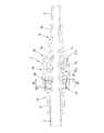
チューブ等の医療構成要素同士を接続するための接続構造は種々のタイプがある。特許文献1に開示されているタイプの接続構造は、図13、図14に示すように、雄型接続装置1と雌型コネクタ2とを備えている。
雄型接続装置1は、雄型コネクタ10と、この雄型コネクタ10に回転可能に取り付けられた螺合筒20とを有している。螺合筒20は、雄型コネクタ10の雄型ルアー部11の径方向外側に位置する螺合部21を有し、この螺合部21の内周には雌ねじ21aが形成されている。
雌型コネクタ2は雌型ルアー部2aを有しており、この雌型ルアー部2aの先端部外周には上記雌ねじ21aに螺合する係合突起2cが形成されている。There are various types of connection structures for connecting medical components such as tubes. As shown in FIGS. 13 and 14, the type of connection structure disclosed in
The
The
図13に示すように、上記螺合筒20の雌ねじ21aと雌型コネクタ2の係合突起2cを螺合させた状態で螺合筒20を締め付け方向に回すと、雄型ルアー部11と雌型ルアー部2aが接合する。さらに螺合筒20を締め付け方向に回すと雄型ルアー部11と雌型ルアー部2aが押圧力をもって強く接合し、十分なシール性能が得られる。 As shown in FIG. 13, when the
図13に示す螺合筒20の締め付け状態では、雌ねじ21aのねじ山の奥側の面21xが係合突起2cに強く当たり、雌型ルアー部2aを雄型ルアー部11に向かって引き付けている。雌ねじ21aのねじ山の奥側の面21xと係合突起2cの摩擦により、螺合筒20はこの雌型ルアー部2aの引き付け状態を維持し、ひいては雄型ルアー部11と雌型ルアー部2aの接合状態を維持する。 In the tightened state of the
しかし、図13に示すように、雌ねじ21aのねじ山の開口端側の面21yと係合突起2cとの間には軸方向のガタGがあり、螺合筒20は振動や意図しないトルク付与により図14に示すように緩み方向に上記ガタGに相当する分だけ回ることがある。これにより、雌ねじ21aのねじ山の開口端側の面21yが係合突起2cに当たり、ねじ山の奥側の面21xと係合突起2cとの間にガタGが形成される。このような状況で、接続構造内を液体が流れると、その流体圧により、上記ガタGの分だけ雄型ルアー部11と雌型ルアー部2aが離れる方向に変位し、その結果、十分なシール性を発揮できなくなり、これら雄型ルアー部11と雌型ルアー部2aの間から液体が漏れることがある。 However, as shown in FIG. 13, there is an axial backlash G between the
特許文献2の図1〜図6には、本発明者が開発したトルクリミット機構付きの医療用接続構造が開示されている。この医療用接続構造でも、上述した図13,図14の接続構造と同様に、螺合筒の緩み方向の回動を禁じることはできない。 FIGS. 1 to 6 of
特許文献3の図73〜図75には、雄型コネクタと螺合筒との間に配置された緩み止め機構が開示されている。この緩み防止機構は、螺合筒の内周に全周にわたって等間隔をなして形成された多数の第1係合突起と、雄型コネクタの外周に形成された第2係合突起との噛み合いにより、螺合筒の緩みを禁じている。 FIGS. 73 to 75 of Patent Document 3 disclose a locking mechanism arranged between the male connector and the screw cylinder. This loosening prevention mechanism engages a large number of first engaging protrusions formed on the inner circumference of the screw cylinder at equal intervals over the entire circumference with a second engaging protrusion formed on the outer circumference of the male connector. Therefore, loosening of the screw cylinder is prohibited.
特許文献3の医療用接続構造では、雄型ルアー部と雌型ルアー部を接合するために螺合筒を締め付け方向に回す際に、緩み止め機構が比較的大きな抵抗となるため、円滑な接合作業が妨げられる。 In the medical connection structure of Patent Document 3, when the screw cylinder is turned in the tightening direction to join the male luer portion and the female luer portion, the loosening prevention mechanism provides a relatively large resistance, so that the joint is smooth. Work is hindered.
本発明は、上記課題を解決するためになされたものであり、筒形状の雄型コネクタと、上記雄型コネクタに回転可能に連結された螺合筒とを備え、上記雄型コネクタが、先端から基端に向かって順に配置された雄型ルアー部と支持部とを有し、上記螺合筒が、先端から基端に向かって順に配置された螺合部と装着部とを有し、上記螺合筒の上記装着部が上記雄型コネクタの上記支持部外周に回転可能に装着され、上記螺合部が内周に雌ねじを有するとともに上記雄型ルアー部の径方向外側に配置されている医療用雄型接続装置において、
さらに、上記雄型コネクタと上記螺合筒との間に配置された緩み防止機構を備え、上記緩み防止機構は、上記雄型コネクタに対する上記螺合筒の緩み方向の回動を禁じるものであり、上記螺合筒の内周に全周にわたって形成されたラチェット歯と、上記雄型コネクタの外周に形成されて周方向に延びその自由端が上記雄型コネクタの外周から離間した少なくとも1つの弾性片と、上記弾性片の自由端に形成されて径方向外方向に突出する係合爪とを有し、
上記螺合筒が締め付け方向の回動トルクを受けた時には、上記弾性片の径方向内方向の弾性変形を伴って上記係合爪が上記ラチェット歯を乗り越えることにより、上記螺合筒の上記雄型コネクタに対する回動を許容し、上記螺合筒が緩み方向の回動トルクを受けた時には、上記係合爪が上記ラチェット歯を係止することにより、上記螺合筒の上記雄型コネクタに対する回動を禁じることを特徴とする。The present invention has been made to solve the above problems, and includes a tubular male connector and a screw cylinder rotatably connected to the male connector, and the male connector has a tip. It has a male lure portion and a support portion that are arranged in order from the tip to the base end, and the screw cylinder has a screw portion and a mounting portion that are arranged in order from the tip to the base end. The mounting portion of the screw cylinder is rotatably mounted on the outer periphery of the support portion of the male connector, and the screw portion has a female screw on the inner circumference and is arranged on the radial outer side of the male lure portion. In the medical male type connection device
Further, a loosening prevention mechanism arranged between the male connector and the screw cylinder is provided, and the loosening prevention mechanism prohibits the screw cylinder from rotating in the loosening direction with respect to the male connector. , The ratchet teeth formed on the inner circumference of the screw cylinder over the entire circumference, and at least one elastic end formed on the outer circumference of the male connector and extending in the circumferential direction with its free end separated from the outer circumference of the male connector. It has a piece and an engaging claw formed at the free end of the elastic piece and projecting outward in the radial direction.
When the screw cylinder receives a rotational torque in the tightening direction, the engaging claw gets over the ratchet teeth with elastic deformation in the radial inward direction of the elastic piece, so that the male of the screw cylinder When the screw cylinder is allowed to rotate with respect to the mold connector and the screw cylinder receives a rotation torque in the loosening direction, the engaging claw locks the ratchet teeth, so that the screw cylinder can be rotated with respect to the male connector. It is characterized by prohibiting rotation.
上記構成によれば、雄型ルアー部が雌型コネクタの雌型ルアー部に接合された状態で、緩み止め機構のラチェット歯と係合爪の噛み合いにより螺合筒が雄型コネクタに対して緩むのを禁じることができ、ルアー部同士の良好な接合状態を維持できる。螺合筒の締め付けの際に、弾性片の径方向内方向への弾性変形を伴って、係合爪が螺合筒のラチェット歯を乗り越えるので、大きな抵抗が生じず、接合作業を円滑に行なうことができる。また、弾性片が周方向に延びているので、螺合筒に締め付け方向または緩み方向の回転トルクが付与された時に、弾性片には捩じる力が付与されず、弾性片の強度を維持できる。 According to the above configuration, with the male luer portion joined to the female luer portion of the female connector, the screw cylinder loosens with respect to the male connector due to the meshing of the ratchet teeth of the locking mechanism and the engaging claws. It is possible to forbid the lure part and maintain a good joint state between the lure parts. When tightening the screw cylinder, the engaging claws get over the ratchet teeth of the screw cylinder with elastic deformation in the radial inward direction of the elastic piece, so that large resistance does not occur and the joining work is performed smoothly. be able to. Further, since the elastic piece extends in the circumferential direction, when a rotational torque in the tightening direction or the loosening direction is applied to the screw cylinder, no twisting force is applied to the elastic piece, and the strength of the elastic piece is maintained. it can.
好ましくは、上記弾性片が上記螺合筒の締め付け方向に延びている。
上記構成によれば、螺合筒が締め付け方向の回転トルクを付与された時に、弾性変形し易く、より一層接合作業を楽にすることができる。また、螺合筒が緩み方向の回転トルクを付与された時に、係合爪のラチェット歯への噛み合いが深まるため、螺合筒の雄型コネクタに対する緩みをより一層確実に防止することができる。Preferably, the elastic piece extends in the tightening direction of the screw cylinder.
According to the above configuration, when the screw cylinder is given a rotational torque in the tightening direction, it is easily elastically deformed, and the joining work can be further facilitated. Further, when the screw cylinder is given a rotational torque in the loosening direction, the engagement claws are deeply engaged with the ratchet teeth, so that the screw cylinder can be more reliably prevented from loosening with respect to the male connector.
好ましくは、上記雄型コネクタの外周には、径方向外方向に突出する支持凸部が形成され、この支持凸部の先端から上記弾性片が周方向に延びている。
上記構成によれば、螺合筒を締め付け方向へ回す際に、弾性片は弾性変形し易く、より一層接合作業を楽にすることができる。Preferably, a support convex portion projecting outward in the radial direction is formed on the outer periphery of the male connector, and the elastic piece extends in the circumferential direction from the tip of the support convex portion.
According to the above configuration, when the screw cylinder is turned in the tightening direction, the elastic piece is easily elastically deformed, and the joining work can be further facilitated.
好ましくは、上記雄型コネクタの外周には、面取された平坦面が形成され、上記平坦面の周方向端部に上記支持凸部が連なっており、上記弾性片が上記平坦面に沿って延びるとともに上記平坦面から離間している。
上記構成によれば、弾性片を雄型コネクタの外周から径方向外方向に大きく突出させずに、径方向内方向への弾性変形が可能である。Preferably, a chamfered flat surface is formed on the outer periphery of the male connector, the support convex portion is connected to the circumferential end portion of the flat surface, and the elastic piece is along the flat surface. It extends and is separated from the flat surface.
According to the above configuration, elastic deformation in the radial inward direction is possible without causing the elastic piece to protrude significantly in the radial outward direction from the outer circumference of the male connector.
好ましくは、上記雄型コネクタの外周には上記弾性片の反対側において上記支持凸部に連なる補強隆起部が形成されている。
上記構成によれば、螺合筒に強い回転トルクが作用して、弾性片に支持凸部に向かう強い力が加わった時でも、補強隆起部で受け止めることができ、弾性片および支持凸部の強度を確実に維持することができる。Preferably, a reinforcing ridge portion connected to the support convex portion is formed on the outer periphery of the male connector on the opposite side of the elastic piece.
According to the above configuration, even when a strong rotational torque acts on the screw cylinder and a strong force is applied to the elastic piece toward the support convex portion, it can be received by the reinforcing ridge portion, and the elastic piece and the support convex portion can be received. The strength can be reliably maintained.
好ましくは、さらに、上記螺合筒の外周に回動可能に装着された操作筒と、上記螺合筒と上記操作筒との間に配置されたトルクリミット機構とを備え、上記トルクリミット機構は、上記操作筒の締め付け方向の回転トルクを上記螺合筒に伝達し、上記回転トルクが設定トルクを越えた時に、上記操作筒を上記螺合筒に対して空回りさせ、上記トルクリミット機構は、上記操作筒の内周に全周にわたって形成された係合歯と、上記螺合筒に形成された少なくとも1つの弾性変形部と、上記弾性変形部に形成されて径方向外方向に突出し上記係合歯に噛み合う第2の係合爪とを有し、上記弾性変形部の弾性係数が上記緩み防止機構の上記弾性片より大きい。
上記構成によれば、螺合筒に過剰なトルクが付与されず、雄型ルアー部と雌型ルアー部が離脱不能な程に噛み付く等の不都合を回避できる。Preferably, the operation cylinder rotatably mounted on the outer periphery of the screw cylinder and the torque limit mechanism arranged between the screw cylinder and the operation cylinder are further provided, and the torque limit mechanism is provided. , The rotation torque in the tightening direction of the operation cylinder is transmitted to the screw cylinder, and when the rotation torque exceeds the set torque, the operation cylinder is idled with respect to the screw cylinder, and the torque limit mechanism Engagement teeth formed on the inner circumference of the operation cylinder, at least one elastically deformed portion formed on the screw cylinder, and the elastically deformed portion formed on the elastically deformed portion and projecting outward in the radial direction. It has a second engaging claw that meshes with the joint tooth, and the elastic coefficient of the elastically deformed portion is larger than that of the elastic piece of the loosening prevention mechanism.
According to the above configuration, an excessive torque is not applied to the screw cylinder, and it is possible to avoid inconveniences such as the male luer portion and the female lure portion biting to the extent that they cannot be separated.
好ましくは、上記螺合筒の上記装着部の端部に上記弾性変形部が形成され、上記装着部の内周には上記弾性変形部に軸方向に隣接して上記緩み防止機構の上記ラチェット歯が形成されている。 Preferably, the elastically deformed portion is formed at the end of the mounting portion of the screw cylinder, and the ratchet teeth of the loosening prevention mechanism are axially adjacent to the elastically deformed portion on the inner circumference of the mounting portion. Is formed.
本発明によれば、螺合筒の締め付け方向の回転の際に緩み防止機構の抵抗が少なく、また、螺合筒に締め付け方向や緩み方向の回転トルクが付与されても、緩み防止機構の弾性片は強度を維持することができる。 According to the present invention, the resistance of the loosening prevention mechanism is small when the screw cylinder is rotated in the tightening direction, and the elasticity of the loosening prevention mechanism is applied even when a rotational torque in the tightening direction or the loosening direction is applied to the screw cylinder. The piece can maintain its strength.
以下、本発明の第1実施形態に係る医療用雄型接続装置について、図1〜図10を参照しながら説明する。本実施形態において図13、図14に示す従来装置に対応する構成部には同番号を付す。
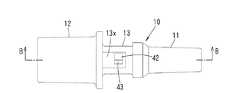
図1に示すように雄型接続装置1は、雌型コネクタ2と協働して、薬液や血液等の液体を流すチューブ5、5’(第1、第2の医療構成要素)を接続するものである。雄型接続装置1の各構成部材および雌型コネクタ2は樹脂により形成されている。Hereinafter, the medical male type connecting device according to the first embodiment of the present invention will be described with reference to FIGS. 1 to 10. In this embodiment, the components corresponding to the conventional devices shown in FIGS. 13 and 14 are assigned the same numbers.
As shown in FIG. 1, the
最初に、構成が簡単な雌型コネクタ2について図1、図2Bを参照しながら説明する。雌型コネクタ2は、細長い筒形状をなし、その軸方向一端部(先端部)に雌型ルアー部2aを有し、他端部(基端部)に連結部2bを有している。雌型ルアー部2aの内面は先端に向かって径が大きくなるような緩やかなテーパをなしている。雌型ルアー部2aの先端部外周には、雄ねじの役割を持つ一対の係合突起2cが周方向に180°離れて形成されている。連結部2bにはチューブ5’の端部が挿入固定される。 First, the
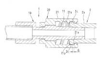
図2A,図3〜図5に示すように、上記雄型接続装置1は、雄型コネクタ10と、この雄型コネクタ10の外周に回転可能かつ軸方向移動不能に取り付けられた螺合筒20と、螺合筒20の外周に回転可能かつ軸方向移動不能に取り付けられた操作筒30とを備えている。 As shown in FIGS. 2A and 3 to 5, the
図6A,図6Bに示すように、上記雄型コネクタ10は細長い筒形状をなし、その軸方向一端部(先端部)に雄型ルアー部11を有し、他端部(基端部)に連結部12を有し、中間部に支持部13を有している。雄型ルアー部11の外面は先端に向かって径が小さくなるような緩やかなテーパをなしている。この雄型ルアー部11の外面のテーパ角は雌型ルアー部2aの内面のテーパ角と実質的に等しい。連結部12にはチューブ5の端部が挿入固定される。 As shown in FIGS. 6A and 6B, the
図7A,図7Bに示すように、上記螺合筒20は、軸方向の一端部(先端部)に螺合部21を有し、他端部(基端部)に装着部22を有している。螺合部21の内周には雌ねじ21aが形成されている。図2Aに示すように、装着部22が雄型コネクタ10の支持部13に回転可能かつ軸方向移動不能に装着されている。 As shown in FIGS. 7A and 7B, the
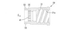
図1、図2Aに示すように、上記螺合筒20の雄型コネクタ10への装着状態において、螺合筒20の螺合部21は雄型ルアー部11の径方向外側に配置されており、螺合部21と雄型ルアー部11の間には環状の挿入空間25が形成されている。雄型コネクタ10の支持部13の小径部と螺合筒20の装着部22との間には、環状空隙26が形成されている。 As shown in FIGS. 1 and 2A, in the mounted state of the
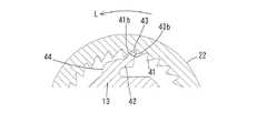
図2Aに示すように、雄型接続装置1は、上記環状空隙26に配置された緩み防止機構40を備えている。この緩み防止機構40は、図5,図7B,図7Cに示すように螺合筒20の装着部22の内周に全周にわたって形成されたラチェット歯41と、図3,図6A〜図6Cに示すように雄型コネクタ10の支持部13の小径部に形成された一対の弾性片42とを有している。 As shown in FIG. 2A, the
ラチェット歯41は、螺合筒20の装着部22において、基端から所定間隔離れた部位に形成されている。図10Aに示すように、ラチェット歯41は、後述する締め付け方向T側が傾斜面41aをなし、緩み方向L側が急峻面41bをなしている。 The
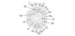
雄型コネクタ10の支持部13の円筒面をなす小径部には、面取された一対の平坦面13xが形成されている。一対の平坦面13xは径方向に対峙し、互いに平行をなしている。
上記支持部13の平坦面13xの周方向端部(緩み方向L側の端部)から、径方向、外方向に支持凸部44が突出しており、この支持凸部44の先端から、上記弾性片42が平坦面13xと略平行をなして締め付け方向T(周方向)に延びている。これら支持凸部44と弾性片42は略L字形をなしている。弾性片42は平坦面13xから離間しており、弾性片42の先端(自由端)には、径方向外方向に突出する係合爪43が形成されている。A pair of chamfered
The support
図9,図10Aに示すように、一対の係合爪43はラチェット歯41に噛み合っている。図10Aに示すように、係合爪43は、緩み方向L側が傾斜面43aをなし,締め付け方向T側が急峻面43bをなしており、ラチェット歯41の傾斜面41aと係合爪43の傾斜面43aが周方向に対峙し、急峻面41b、43bが周方向に対峙している。 As shown in FIGS. 9 and 10A, the pair of engaging
図2Aに示すように、本実施形態の雄型接続装置1は、螺合筒20と操作筒30との間に配置されたトルクリミット機構50をも備えている。トルクリミット機構50は、図5、図8に示すように操作筒30の基端部内周に全周にわたって形成された係合歯51と、図3、図5、図7に示すように螺合筒20の基端部に形成された弾性変形部52と、を備えている。
図8B、図9に示すように、係合歯51は緩み防止機構40のラチェット歯41と同様に、締め付け方向T側が傾斜面51aをなし、緩み方向L側が急峻面51bをなしている。As shown in FIG. 2A, the
As shown in FIGS. 8B and 9, the engaging
図3、図5、図7に示すように、螺合筒20の装着部22の端部には、周方向に180°離れて一対のスリット54が形成されている。このスリット54は、装着部22の端から軸方向に延びている。このスリット54に隣接した部位が弾性変形部52として提供される。弾性変形部52は緩み防止機構40のラチェット歯41に軸方向に隣接している。弾性変形部52の弾性係数は緩み防止機構40の弾性片42よりはるかに大きい。 As shown in FIGS. 3, 5, and 7, a pair of
各弾性変形部52の外面には、スリット54に隣接した位置に係合爪53(第2の係合爪)が形成されるとともに、この係合爪53から上記係合歯51の1ピッチ分だけ周方向に離れたもう一つの係合爪53(第2の係合爪)が形成されている。図9に示すように、これら係合爪53は径方向外方向に突出して上記係合歯51と噛み合っている。 An engaging claw 53 (second engaging claw) is formed on the outer surface of each elastically
係合爪53は、緩み防止機構40の係合爪43と同様に、緩み方向L側が傾斜面53aをなし,締め付け方向T側が急峻面53bをなしており、噛み合い状態において、係合歯51の傾斜面51aと係合爪53の傾斜面53aが周方向に対峙し、急峻面51b、53bが周方向に対峙している。 Similar to the engaging
上記構成をなす雄型接続装置1に雌型コネクタ2を近づけ、雄型ルアー部11を雌型ルアー部2aに挿入する。上記挿入は、上記雌型コネクタ2の係合突起2cが雄型接続装置1の螺合筒20の雌ねじ21aに当たるまで抵抗なく進められる。 The
次に、操作筒30を締め付け方向Tに回すと、操作筒30のトルクがトルクリミット機構50を介して螺合筒20に伝達される。トルクリミット機構50の弾性変形部52の弾性係数が大きいので、トルクリミット機構50の係合歯51の傾斜面51aと係合爪53の傾斜面53aが当たった状態で、係合歯51と係合爪53の噛み合い状態が維持されており、操作筒30と螺合筒20は一緒に回る。 Next, when the
上記のように螺合筒20が締め付け方向Tに回る時に、図10Bに示すように緩み防止機構40の係合爪43の傾斜面43aがラチェット歯41の傾斜面41aを滑るため、係合爪43は螺合筒20のラチェット歯41を乗り越えることができる。この際、弾性片42の径方向内方向の弾性変形を伴うため、螺合筒20は緩み防止機構40からの大きな抵抗を受けることなく雄型コネクタ10に対して回すことができる。 When the
上記のように螺合筒20を締め付け方向Tに回すことにより、雌ねじ21aと係合突起2cとの螺合が進み、雄型ルアー部11と雌型ルアー部2aが押圧力をもって接合する。このようにして、十分なシール性能で雄型ルアー部11と雌型ルアー部2aを接合することができる。この状態では、図2Bに示すように、螺合筒20の雌ねじ21aのねじ山の奥側の面21xが、雌型コネクタ2の係合突起2cに当たっている。 By turning the
さらに操作筒30を回そうとすると、雄型ルアー部11と雌型ルアー部2aの接合部から大きな抵抗を受け、回転トルクが設定トルクを超える。すると、係合爪53の傾斜面53aが係合歯51の傾斜面51aを滑り、弾性変形部52の径方向内方向の弾性変形を伴って、係合爪53が操作筒30の係合歯51を乗り越える。このように、操作筒30が螺合筒20に対して空回りし、操作筒30の回転トルクが螺合筒20に伝達されないため、螺合筒20に過剰なトルクが付与されず、雄型ルアー部11と雌型ルアー部2aとの間の押圧力が過剰になるのを回避できる。その結果、雄型ルアー部11や雌型ルアー部2aの破損を防止でき、雄型ルアー部11と雌型ルアー部2aが離脱不能な程度に噛み付くのを回避できる。 Further, when the
上記の接合状態において、図10Cに示すように、螺合筒20に意図しない緩み方向Lのトルクが加わっても、螺合筒20は雄型コネクタ10に対して緩み方向の回動を阻止される。ラチェット歯41の急峻面41bが係合爪43の急峻面43bに係止されているからである。 In the above-mentioned joining state, as shown in FIG. 10C, even if an unintended torque in the loosening direction L is applied to the
上記のように雄型ルアー部11と雌型ルアー部2aの接合完了後に、螺合筒20が雄型コネクタ10に対して緩み方向に回わらないので、図2Bに示すように、螺合筒20の雌ねじ21aのねじ山の奥側の面21xが、雌型コネクタ2の係合突起2cに当たった状態が維持される。その結果、流体の圧力が高い場合でも、雌型ルアー部2aと雄型ルアー部11が離れる方向に変位することがなく、十分なシール性能を維持でき、ひいては流体の漏れを禁じることができる。 As described above, after the joining of the
上記のようにしてチューブ5、5’を接続した後、接続の解除が必要になった場合には、操作筒30を緩み方向Lに回す。すると、トルクリミット機構50において、操作筒30の係合歯51の急峻面51bが螺合筒20の係合爪53の急峻面53bに当たり、螺合筒20が操作筒30と一緒に緩み方向に回る。これと同時に、緩み防止機構40において、螺合筒20のラチェット歯41の急峻面41bが雄型コネクタ10の係合片43の急峻面43bに当たり、雄型コネクタ10も螺合筒20と一緒に回る。その結果、雄型ルアー部11と雌型ルアー部2aの接合状態が解除される。 After connecting the
本実施形態では、緩み防止機構40の弾性片42が周方向に延びているため、次の利点がある。
上述したように螺合筒20が緩み方向Lの回転トルクを受けた時、ラチェット歯41の急峻面41bと係合爪43の急峻面43bの係止により、弾性片42には周方向の力が作用する。また、螺合筒20が締め付け方向Tの回転トルクを受けた時にも、ラチェット歯41の傾斜面41aと係合爪43の傾斜面43aの摩擦によって、弾性片42には周方向の力が作用する。しかし、弾性片42は周方向に延びているため、上記のような周方向の力によって捩れが生じず、弾性片42の強度を維持することができる。In the present embodiment, since the
As described above, when the
本実施形態では、弾性片42が周方向に締め付け方向Tに延びているので、螺合筒20が締め付け方向Tの回転トルクを付与された時に、弾性変形し易く、より一層接合作業を楽にすることができる。また、螺合筒20が緩み方向Lの回転トルクを付与された時に、係合爪43を介して弾性片42には弾性片43を起こす方向の力が付与され、これにより係合爪43のラチェット歯41への噛み合いが深まるため、螺合筒20の雄型コネクタ10に対する緩みをより一層確実に防止することができる。 In the present embodiment, since the
本実施形態では、雄型コネクタ10の支持部13の外周から径方向、外方向に突出する支持凸部44が形成され、この支持凸部44の先端から弾性片42が周方向に延びており、主として支持凸部44,弾性片42の交叉部を支点として弾性片42が径方向内方向に弾性変形するので、螺合筒20を締め付け方向Tへ回す際の抵抗をより一層小さくすることができる。 In the present embodiment, a support
本実施形態では、弾性片42は雄型コネクタ10の支持部13の平坦面13xに沿って配置されているので、弾性片42を支持部13から径方向外方向に大きく突出させずに、径方向内方向への弾性変形が可能である。 In the present embodiment, since the
次に、本発明の第2実施形態について図11、図12を参照しながら説明する。本実施形態は、雄型コネクタ10の要部を除いて他の構成要素は第1実施形態と同じである。本実施形態の雄型コネクタ10では、支持部13の小径部外周に補強隆起部45が形成されている。この補強隆起部45は、弾性片42の反対側において支持凸部44に連なっている。 Next, the second embodiment of the present invention will be described with reference to FIGS. 11 and 12. In this embodiment, other components are the same as those in the first embodiment except for the main part of the
本実施形態によれば、螺合筒20に強い回転トルクが作用して、弾性片42に支持凸部44に向かう強い力が加わった時でも、補強隆起部45で受け止めることができ、弾性片42および支持凸部44の強度を確実に維持することができる。 According to the present embodiment, even when a strong rotational torque acts on the
本発明は上記実施形態に制約されず、種々の態様が可能である。
緩み防止機構の弾性片は周方向において緩み方向に延びていてもよい。
操作筒とトルクリミット機構は省いてもよい。
雄型コネクタの装着部と連結部が分離して互いに回動可能であってもよい。
本発明を三方活栓とチューブの接続に適用してもよいし、あらゆる医療用構成要素の接続に適用することができる。The present invention is not limited to the above embodiment, and various aspects are possible.
The elastic piece of the loosening prevention mechanism may extend in the loosening direction in the circumferential direction.
The operating cylinder and torque limit mechanism may be omitted.
The mounting portion and the connecting portion of the male connector may be separated and rotatable with each other.
The present invention may be applied to the connection between a three-way stopcock and a tube, or to the connection of any medical component.
本発明は、医療用の接続構造に用いられる雄型接続装置に適用することができる。 The present invention can be applied to a male connecting device used in a medical connection structure.
Claims (7)
Translated fromJapanese上記雄型コネクタが、先端から基端に向かって順に配置された雄型ルアー部(11)と支持部(13)とを有し、
上記螺合筒(20)が、先端から基端に向かって順に配置された螺合部(21)と装着部(22)とを有し、
上記螺合筒の上記装着部(22)が上記雄型コネクタの上記支持部(13)外周に回転可能に装着され、上記螺合部が内周に雌ねじ(21a)を有するとともに上記雄型ルアー部(11)の径方向外側に配置されている医療用雄型接続装置において、
さらに、上記雄型コネクタ(10)と上記螺合筒(20)との間に配置された緩み防止機構(40)を備え、上記緩み防止機構は、上記雄型コネクタに対する上記螺合筒の緩み方向の回動を禁じるものであり、上記螺合筒の内周に全周にわたって形成されたラチェット歯(41)と、上記雄型コネクタの外周に形成されて周方向に延びその自由端が上記雄型コネクタ(10)の外周から離間した少なくとも1つの弾性片(42)と、上記弾性片の自由端に形成されて径方向外方向に突出する係合爪(43)とを有し、
上記螺合筒(20)が締め付け方向の回動トルクを受けた時には、上記弾性片(42)の径方向内方向の弾性変形を伴って上記係合爪(43)が上記ラチェット歯(41)を乗り越えることにより、上記螺合筒の上記雄型コネクタ(10)に対する回動を許容し、
上記螺合筒(20)が緩み方向の回動トルクを受けた時には、上記係合爪(43)が上記ラチェット歯(41)を係止することにより、上記螺合筒の上記雄型コネクタ(10)に対する回動を禁じることを特徴とする医療用雄型接続装置。A tubular male connector (10) and a screw cylinder (20) rotatably connected to the male connector are provided.
The male connector has a male luer portion (11) and a support portion (13) arranged in order from the tip end to the base end.
The screw cylinder (20) has a screw portion (21) and a mounting portion (22) arranged in order from the tip end to the base end.
The mounting portion (22) of the screw cylinder is rotatably mounted on the outer periphery of the support portion (13) of the male connector, and the screw portion has a female screw (21a) on the inner circumference and the male lure. In the medical male connector arranged outside the portion (11) in the radial direction,
Further, a loosening prevention mechanism (40) arranged between the male connector (10) and the screw cylinder (20) is provided, and the loosening prevention mechanism is such that the screw cylinder is loosened with respect to the male connector. Rotation in the direction is prohibited, and the ratchet teeth (41) formed on the inner circumference of the screw cylinder over the entire circumference and the free ends thereof formed on the outer circumference of the male connector and extending in the circumferential direction are described above. It has at least one elastic piece (42) separated from the outer periphery of the male connector (10), and an engaging claw (43) formed at the free end of the elastic piece and projecting outward in the radial direction.
When the screw cylinder (20) receives a rotational torque in the tightening direction, the engaging claw (43) is accompanied by elastic deformation in the radial inward direction of the elastic piece (42), and the ratchet tooth (41). Allows the screw cylinder to rotate with respect to the male connector (10) by overcoming the above.
When the screw cylinder (20) receives a rotational torque in the loosening direction, the engaging claw (43) locks the ratchet teeth (41), whereby the male connector (male connector) of the screw cylinder (20). A medical male connector characterized by prohibiting rotation with respect to 10).
上記平坦面の周方向端部に上記支持凸部(44)が連なっており、上記弾性片(42)が上記平坦面に沿って延びるとともに上記平坦面から離間していることを特徴とする請求項3に記載の医療用雄型接続装置。A chamfered flat surface (13x) is formed on the outer circumference of the male connector (10).
A claim characterized in that the support convex portion (44) is connected to the circumferential end portion of the flat surface, and the elastic piece (42) extends along the flat surface and is separated from the flat surface. Item 3. The medical male type connection device according to item 3.
上記トルクリミット機構は、上記操作筒の締め付け方向の回転トルクを上記螺合筒に伝達し、上記回転トルクが設定トルクを越えた時に、上記操作筒を上記螺合筒に対して空回りさせ、
上記トルクリミット機構は、上記操作筒の内周に全周にわたって形成された係合歯(51)と、上記螺合筒に形成された少なくとも1つの弾性変形部(52)と、上記弾性変形部に形成されて径方向外方向に突出し上記係合歯に噛み合う第2の係合爪(53)とを有し、上記弾性変形部の弾性係数が上記緩み防止機構の上記弾性片より大きいことを特徴とする請求項1に記載の医療用雄型接続構造。Further, it is provided with an operation cylinder (30) rotatably mounted on the outer circumference of the screw cylinder, and a torque limit mechanism (50) arranged between the screw cylinder (20) and the operation cylinder. ,
The torque limit mechanism transmits the rotational torque in the tightening direction of the operation cylinder to the screw cylinder, and when the rotation torque exceeds the set torque, the operation cylinder is idled with respect to the screw cylinder.
The torque limit mechanism includes an engaging tooth (51) formed on the inner circumference of the operating cylinder, at least one elastically deformed portion (52) formed on the screwed cylinder, and the elastically deformed portion. It has a second engaging claw (53) formed in the shape of the elastic deformed portion, which protrudes outward in the radial direction and meshes with the engaging tooth, and the elastic modulus of the elastically deformed portion is larger than that of the elastic piece of the loosening prevention mechanism. The medical male type connection structure according to claim 1.
Applications Claiming Priority (3)
| Application Number | Priority Date | Filing Date | Title |
|---|---|---|---|
| JP2018188958 | 2018-10-04 | ||
| JP2018188958 | 2018-10-04 | ||
| PCT/JP2019/034165WO2020071024A1 (en) | 2018-10-04 | 2019-08-30 | Male connection device for medical use |
Publications (2)
| Publication Number | Publication Date |
|---|---|
| JPWO2020071024A1true JPWO2020071024A1 (en) | 2021-05-20 |
| JP7020724B2 JP7020724B2 (en) | 2022-02-16 |
Family
ID=70054737
Family Applications (2)
| Application Number | Title | Priority Date | Filing Date |
|---|---|---|---|
| JP2020550003AActiveJP6918324B2 (en) | 2018-10-04 | 2019-08-15 | Medical connection structure |
| JP2020550205AActiveJP7020724B2 (en) | 2018-10-04 | 2019-08-30 | Male medical connection device |
Family Applications Before (1)
| Application Number | Title | Priority Date | Filing Date |
|---|---|---|---|
| JP2020550003AActiveJP6918324B2 (en) | 2018-10-04 | 2019-08-15 | Medical connection structure |
Country Status (5)
| Country | Link |
|---|---|
| US (2) | US11872366B2 (en) |
| EP (2) | EP3777957B8 (en) |
| JP (2) | JP6918324B2 (en) |
| CN (2) | CN112261967B (en) |
| WO (2) | WO2020070983A1 (en) |
Families Citing this family (10)
| Publication number | Priority date | Publication date | Assignee | Title |
|---|---|---|---|---|
| JP7385917B2 (en)* | 2019-12-26 | 2023-11-24 | 株式会社タカギ | Fittings with ratchet mechanism |
| US11554258B2 (en)* | 2020-02-26 | 2023-01-17 | Becton, Dickinson And Company | Syringe with snap-in enteral connection feature |
| IL305598A (en) | 2021-03-03 | 2023-11-01 | Equashield Medical Ltd | Sealed lower connector and valve assembly to adapter |
| CN114225211A (en)* | 2021-11-30 | 2022-03-25 | 宁波天益医疗器械股份有限公司 | Ruhr joint |
| CN115059811B (en)* | 2022-06-08 | 2023-09-15 | 东台市创成建筑科技有限公司 | Pipeline anti-burst anti-twisting connecting pipe fitting |
| TWI819713B (en)* | 2022-07-19 | 2023-10-21 | 緯創資通股份有限公司 | Quick coupling set and plug and socket thereof |
| TWI865046B (en)* | 2022-10-11 | 2024-12-01 | 光紅建聖股份有限公司 | Electrical connector assembly |
| US20240139490A1 (en)* | 2022-10-31 | 2024-05-02 | Becton, Dickinson And Company | Luer connector for vascular access devices |
| USD1055279S1 (en) | 2023-04-17 | 2024-12-24 | iMed Technology, Inc. | Feeding tube set inlet component |
| USD1069109S1 (en)* | 2023-04-17 | 2025-04-01 | iMed Technology, Inc. | Feeding tube set inlet component |
Citations (6)
| Publication number | Priority date | Publication date | Assignee | Title |
|---|---|---|---|---|
| JPS4823058Y1 (en)* | 1968-11-25 | 1973-07-05 | ||
| JPS566499U (en)* | 1979-06-28 | 1981-01-20 | ||
| JPH09182878A (en)* | 1995-12-28 | 1997-07-15 | Seikouken Kk | Hand winding type spring driving unit |
| US6152913A (en)* | 1995-04-27 | 2000-11-28 | The Kippgroup | Medical luer connection having protective cap with crush rib |
| US20080172039A1 (en)* | 2006-10-02 | 2008-07-17 | B. Braun Medical Inc. | Ratcheting luer lock connector |
| WO2016157974A1 (en)* | 2015-04-02 | 2016-10-06 | 光陽産業株式会社 | Medical connection structure |
Family Cites Families (13)
| Publication number | Priority date | Publication date | Assignee | Title |
|---|---|---|---|---|
| JPS566499A (en) | 1979-06-26 | 1981-01-23 | Sanyo Electric Co | Hybrid integrated circuit unit |
| JPS5987840A (en) | 1982-11-10 | 1984-05-21 | Toray Silicone Co Ltd | Semiconductor device |
| JPS5987840U (en) | 1982-12-07 | 1984-06-14 | 住友ベークライト株式会社 | luer lock connector |
| DE20109061U1 (en) | 2001-05-31 | 2001-08-09 | B. Braun Melsungen Ag, 34212 Melsungen | Patient safety connector |
| US7998134B2 (en) | 2007-05-16 | 2011-08-16 | Icu Medical, Inc. | Medical connector |
| US7984933B2 (en)* | 2008-02-28 | 2011-07-26 | Diba Industries, Inc. | Multi-use torque fitting and compressible ferrule |
| US8790327B2 (en)* | 2010-03-30 | 2014-07-29 | Terumo Kabushiki Kaisha | Connector and connector assembly |
| US8888143B2 (en)* | 2011-09-23 | 2014-11-18 | Diba Industries, Inc. | Torque limiting fastening assemblies and fluid coupling assemblies including the same |
| US9764123B2 (en)* | 2012-02-13 | 2017-09-19 | Nipro Corporation | Needle-less connector |
| JP6001903B2 (en)* | 2012-03-30 | 2016-10-05 | 大研医器株式会社 | Connecting member |
| US9279526B2 (en) | 2013-03-14 | 2016-03-08 | Mcalister Technologies, Llc | Apparatuses and methods for providing finger-tightened and ratchet-secured connections between conduits |
| US10864145B2 (en)* | 2013-12-11 | 2020-12-15 | Jms Co., Ltd. | Male connector |
| CN109041571B (en) | 2017-04-12 | 2020-11-24 | 光阳产业股份有限公司 | Medical connection structure |
- 2019
- 2019-08-15USUS17/053,993patent/US11872366B2/enactiveActive
- 2019-08-15EPEP19868858.2Apatent/EP3777957B8/enactiveActive
- 2019-08-15JPJP2020550003Apatent/JP6918324B2/enactiveActive
- 2019-08-15WOPCT/JP2019/032019patent/WO2020070983A1/ennot_activeCeased
- 2019-08-15CNCN201980039264.9Apatent/CN112261967B/enactiveActive
- 2019-08-30EPEP19868995.2Apatent/EP3777958B1/enactiveActive
- 2019-08-30JPJP2020550205Apatent/JP7020724B2/enactiveActive
- 2019-08-30CNCN201980039149.1Apatent/CN112261966B/enactiveActive
- 2019-08-30USUS17/054,377patent/US12083308B2/enactiveActive
- 2019-08-30WOPCT/JP2019/034165patent/WO2020071024A1/ennot_activeCeased
Patent Citations (6)
| Publication number | Priority date | Publication date | Assignee | Title |
|---|---|---|---|---|
| JPS4823058Y1 (en)* | 1968-11-25 | 1973-07-05 | ||
| JPS566499U (en)* | 1979-06-28 | 1981-01-20 | ||
| US6152913A (en)* | 1995-04-27 | 2000-11-28 | The Kippgroup | Medical luer connection having protective cap with crush rib |
| JPH09182878A (en)* | 1995-12-28 | 1997-07-15 | Seikouken Kk | Hand winding type spring driving unit |
| US20080172039A1 (en)* | 2006-10-02 | 2008-07-17 | B. Braun Medical Inc. | Ratcheting luer lock connector |
| WO2016157974A1 (en)* | 2015-04-02 | 2016-10-06 | 光陽産業株式会社 | Medical connection structure |
Also Published As
| Publication number | Publication date |
|---|---|
| EP3777957A1 (en) | 2021-02-17 |
| EP3777958B1 (en) | 2025-09-24 |
| EP3777957B1 (en) | 2024-07-03 |
| JP6918324B2 (en) | 2021-08-11 |
| JP7020724B2 (en) | 2022-02-16 |
| CN112261966A (en) | 2021-01-22 |
| EP3777957A4 (en) | 2021-12-22 |
| EP3777958A1 (en) | 2021-02-17 |
| JPWO2020070983A1 (en) | 2021-05-13 |
| WO2020070983A1 (en) | 2020-04-09 |
| CN112261966B (en) | 2022-07-26 |
| WO2020071024A1 (en) | 2020-04-09 |
| EP3777957B8 (en) | 2024-08-07 |
| US20210213271A1 (en) | 2021-07-15 |
| US12083308B2 (en) | 2024-09-10 |
| CN112261967A (en) | 2021-01-22 |
| US11872366B2 (en) | 2024-01-16 |
| US20210085951A1 (en) | 2021-03-25 |
| CN112261967B (en) | 2022-07-26 |
| EP3777958A4 (en) | 2022-01-26 |
Similar Documents
| Publication | Publication Date | Title |
|---|---|---|
| JP7020724B2 (en) | Male medical connection device | |
| JP6462900B1 (en) | Medical connection structure | |
| US6224588B1 (en) | Flexible finger latching mechanism | |
| JP6468678B2 (en) | Medical connection structure | |
| JP5650722B2 (en) | Luer lock connector | |
| US7571937B2 (en) | Fluid coupling assembly with integral retention mechanism | |
| JP3178198U (en) | Connector for hose connection | |
| JP2961532B1 (en) | Tightening regulator made of synthetic resin for fastening members for joints | |
| JP6611357B2 (en) | Anti-rotation device for hydraulic connector | |
| JP4852369B2 (en) | Pipe fitting | |
| CN114729720A (en) | Pipe fittings and method of assembling pipe fittings for receiving, retaining and releasing pipes | |
| KR20200014651A (en) | Clamp for pipe | |
| JPH04296291A (en) | Pipe joint | |
| JP6599528B2 (en) | Medical connection structure | |
| JP5584378B1 (en) | Pipe fitting | |
| JP2025067410A (en) | Medical male connection device | |
| JP3151344U (en) | Medical connector | |
| JP2024102610A (en) | Medical male type connection device | |
| JP2007170660A (en) | Joint structure of pipe body and joint device | |
| JP2023071573A (en) | Medical connection device | |
| JP2009210131A (en) | Pipe joint for plastic resin pipe | |
| JPH0649812U (en) | Locking mechanism |
Legal Events
| Date | Code | Title | Description |
|---|---|---|---|
| A621 | Written request for application examination | Free format text:JAPANESE INTERMEDIATE CODE: A621 Effective date:20201027 | |
| A521 | Request for written amendment filed | Free format text:JAPANESE INTERMEDIATE CODE: A523 Effective date:20201127 | |
| A131 | Notification of reasons for refusal | Free format text:JAPANESE INTERMEDIATE CODE: A131 Effective date:20210803 | |
| A521 | Request for written amendment filed | Free format text:JAPANESE INTERMEDIATE CODE: A523 Effective date:20210907 | |
| TRDD | Decision of grant or rejection written | ||
| A01 | Written decision to grant a patent or to grant a registration (utility model) | Free format text:JAPANESE INTERMEDIATE CODE: A01 Effective date:20220118 | |
| A61 | First payment of annual fees (during grant procedure) | Free format text:JAPANESE INTERMEDIATE CODE: A61 Effective date:20220127 | |
| R150 | Certificate of patent or registration of utility model | Ref document number:7020724 Country of ref document:JP Free format text:JAPANESE INTERMEDIATE CODE: R150 |