JPWO2020066964A1 - Vehicle display control devices, in-vehicle device operation systems, methods, and GUI programs - Google Patents
Vehicle display control devices, in-vehicle device operation systems, methods, and GUI programsDownload PDFInfo
- Publication number
- JPWO2020066964A1 JPWO2020066964A1JP2020549186AJP2020549186AJPWO2020066964A1JP WO2020066964 A1JPWO2020066964 A1JP WO2020066964A1JP 2020549186 AJP2020549186 AJP 2020549186AJP 2020549186 AJP2020549186 AJP 2020549186AJP WO2020066964 A1JPWO2020066964 A1JP WO2020066964A1
- Authority
- JP
- Japan
- Prior art keywords
- display area
- vehicle
- position signal
- predetermined range
- menu item
- Prior art date
- Legal status (The legal status is an assumption and is not a legal conclusion. Google has not performed a legal analysis and makes no representation as to the accuracy of the status listed.)
- Granted
Links
Images


Classifications
- B—PERFORMING OPERATIONS; TRANSPORTING
- B60—VEHICLES IN GENERAL
- B60K—ARRANGEMENT OR MOUNTING OF PROPULSION UNITS OR OF TRANSMISSIONS IN VEHICLES; ARRANGEMENT OR MOUNTING OF PLURAL DIVERSE PRIME-MOVERS IN VEHICLES; AUXILIARY DRIVES FOR VEHICLES; INSTRUMENTATION OR DASHBOARDS FOR VEHICLES; ARRANGEMENTS IN CONNECTION WITH COOLING, AIR INTAKE, GAS EXHAUST OR FUEL SUPPLY OF PROPULSION UNITS IN VEHICLES
- B60K35/00—Instruments specially adapted for vehicles; Arrangement of instruments in or on vehicles
- B60K35/10—Input arrangements, i.e. from user to vehicle, associated with vehicle functions or specially adapted therefor
- B—PERFORMING OPERATIONS; TRANSPORTING
- B60—VEHICLES IN GENERAL
- B60K—ARRANGEMENT OR MOUNTING OF PROPULSION UNITS OR OF TRANSMISSIONS IN VEHICLES; ARRANGEMENT OR MOUNTING OF PLURAL DIVERSE PRIME-MOVERS IN VEHICLES; AUXILIARY DRIVES FOR VEHICLES; INSTRUMENTATION OR DASHBOARDS FOR VEHICLES; ARRANGEMENTS IN CONNECTION WITH COOLING, AIR INTAKE, GAS EXHAUST OR FUEL SUPPLY OF PROPULSION UNITS IN VEHICLES
- B60K35/00—Instruments specially adapted for vehicles; Arrangement of instruments in or on vehicles
- B60K35/20—Output arrangements, i.e. from vehicle to user, associated with vehicle functions or specially adapted therefor
- B60K35/21—Output arrangements, i.e. from vehicle to user, associated with vehicle functions or specially adapted therefor using visual output, e.g. blinking lights or matrix displays
- B60K35/22—Display screens
- B—PERFORMING OPERATIONS; TRANSPORTING
- B60—VEHICLES IN GENERAL
- B60K—ARRANGEMENT OR MOUNTING OF PROPULSION UNITS OR OF TRANSMISSIONS IN VEHICLES; ARRANGEMENT OR MOUNTING OF PLURAL DIVERSE PRIME-MOVERS IN VEHICLES; AUXILIARY DRIVES FOR VEHICLES; INSTRUMENTATION OR DASHBOARDS FOR VEHICLES; ARRANGEMENTS IN CONNECTION WITH COOLING, AIR INTAKE, GAS EXHAUST OR FUEL SUPPLY OF PROPULSION UNITS IN VEHICLES
- B60K35/00—Instruments specially adapted for vehicles; Arrangement of instruments in or on vehicles
- B60K35/20—Output arrangements, i.e. from vehicle to user, associated with vehicle functions or specially adapted therefor
- B60K35/21—Output arrangements, i.e. from vehicle to user, associated with vehicle functions or specially adapted therefor using visual output, e.g. blinking lights or matrix displays
- B60K35/23—Head-up displays [HUD]
- B—PERFORMING OPERATIONS; TRANSPORTING
- B60—VEHICLES IN GENERAL
- B60K—ARRANGEMENT OR MOUNTING OF PROPULSION UNITS OR OF TRANSMISSIONS IN VEHICLES; ARRANGEMENT OR MOUNTING OF PLURAL DIVERSE PRIME-MOVERS IN VEHICLES; AUXILIARY DRIVES FOR VEHICLES; INSTRUMENTATION OR DASHBOARDS FOR VEHICLES; ARRANGEMENTS IN CONNECTION WITH COOLING, AIR INTAKE, GAS EXHAUST OR FUEL SUPPLY OF PROPULSION UNITS IN VEHICLES
- B60K35/00—Instruments specially adapted for vehicles; Arrangement of instruments in or on vehicles
- B60K35/20—Output arrangements, i.e. from vehicle to user, associated with vehicle functions or specially adapted therefor
- B60K35/26—Output arrangements, i.e. from vehicle to user, associated with vehicle functions or specially adapted therefor using acoustic output
- B60K35/265—Voice
- B—PERFORMING OPERATIONS; TRANSPORTING
- B60—VEHICLES IN GENERAL
- B60K—ARRANGEMENT OR MOUNTING OF PROPULSION UNITS OR OF TRANSMISSIONS IN VEHICLES; ARRANGEMENT OR MOUNTING OF PLURAL DIVERSE PRIME-MOVERS IN VEHICLES; AUXILIARY DRIVES FOR VEHICLES; INSTRUMENTATION OR DASHBOARDS FOR VEHICLES; ARRANGEMENTS IN CONNECTION WITH COOLING, AIR INTAKE, GAS EXHAUST OR FUEL SUPPLY OF PROPULSION UNITS IN VEHICLES
- B60K35/00—Instruments specially adapted for vehicles; Arrangement of instruments in or on vehicles
- B60K35/80—Arrangements for controlling instruments
- B60K35/81—Arrangements for controlling instruments for controlling displays
- B—PERFORMING OPERATIONS; TRANSPORTING
- B60—VEHICLES IN GENERAL
- B60R—VEHICLES, VEHICLE FITTINGS, OR VEHICLE PARTS, NOT OTHERWISE PROVIDED FOR
- B60R16/00—Electric or fluid circuits specially adapted for vehicles and not otherwise provided for; Arrangement of elements of electric or fluid circuits specially adapted for vehicles and not otherwise provided for
- B60R16/02—Electric or fluid circuits specially adapted for vehicles and not otherwise provided for; Arrangement of elements of electric or fluid circuits specially adapted for vehicles and not otherwise provided for electric constitutive elements
- B60R16/023—Electric or fluid circuits specially adapted for vehicles and not otherwise provided for; Arrangement of elements of electric or fluid circuits specially adapted for vehicles and not otherwise provided for electric constitutive elements for transmission of signals between vehicle parts or subsystems
- B60R16/027—Electric or fluid circuits specially adapted for vehicles and not otherwise provided for; Arrangement of elements of electric or fluid circuits specially adapted for vehicles and not otherwise provided for electric constitutive elements for transmission of signals between vehicle parts or subsystems between relatively movable parts of the vehicle, e.g. between steering wheel and column
- G—PHYSICS
- G06—COMPUTING OR CALCULATING; COUNTING
- G06F—ELECTRIC DIGITAL DATA PROCESSING
- G06F3/00—Input arrangements for transferring data to be processed into a form capable of being handled by the computer; Output arrangements for transferring data from processing unit to output unit, e.g. interface arrangements
- G06F3/01—Input arrangements or combined input and output arrangements for interaction between user and computer
- G06F3/03—Arrangements for converting the position or the displacement of a member into a coded form
- G06F3/041—Digitisers, e.g. for touch screens or touch pads, characterised by the transducing means
- G—PHYSICS
- G06—COMPUTING OR CALCULATING; COUNTING
- G06F—ELECTRIC DIGITAL DATA PROCESSING
- G06F3/00—Input arrangements for transferring data to be processed into a form capable of being handled by the computer; Output arrangements for transferring data from processing unit to output unit, e.g. interface arrangements
- G06F3/01—Input arrangements or combined input and output arrangements for interaction between user and computer
- G06F3/048—Interaction techniques based on graphical user interfaces [GUI]
- G06F3/0481—Interaction techniques based on graphical user interfaces [GUI] based on specific properties of the displayed interaction object or a metaphor-based environment, e.g. interaction with desktop elements like windows or icons, or assisted by a cursor's changing behaviour or appearance
- G06F3/0482—Interaction with lists of selectable items, e.g. menus
- G—PHYSICS
- G06—COMPUTING OR CALCULATING; COUNTING
- G06F—ELECTRIC DIGITAL DATA PROCESSING
- G06F3/00—Input arrangements for transferring data to be processed into a form capable of being handled by the computer; Output arrangements for transferring data from processing unit to output unit, e.g. interface arrangements
- G06F3/01—Input arrangements or combined input and output arrangements for interaction between user and computer
- G06F3/048—Interaction techniques based on graphical user interfaces [GUI]
- G06F3/0487—Interaction techniques based on graphical user interfaces [GUI] using specific features provided by the input device, e.g. functions controlled by the rotation of a mouse with dual sensing arrangements, or of the nature of the input device, e.g. tap gestures based on pressure sensed by a digitiser
- G06F3/0488—Interaction techniques based on graphical user interfaces [GUI] using specific features provided by the input device, e.g. functions controlled by the rotation of a mouse with dual sensing arrangements, or of the nature of the input device, e.g. tap gestures based on pressure sensed by a digitiser using a touch-screen or digitiser, e.g. input of commands through traced gestures
Landscapes
- Engineering & Computer Science (AREA)
- Mechanical Engineering (AREA)
- Chemical & Material Sciences (AREA)
- Combustion & Propulsion (AREA)
- Transportation (AREA)
- Theoretical Computer Science (AREA)
- General Engineering & Computer Science (AREA)
- Human Computer Interaction (AREA)
- Physics & Mathematics (AREA)
- General Physics & Mathematics (AREA)
- User Interface Of Digital Computer (AREA)
- Instrument Panels (AREA)
- Position Input By Displaying (AREA)
Abstract
Translated fromJapaneseDescription
Translated fromJapanese本開示は、例えば、自動車等の車両に搭載される車両用表示制御装置、車載機器操作システム、方法、及びGUIプログラム等に関する。 The present disclosure relates to, for example, a vehicle display control device mounted on a vehicle such as an automobile, an in-vehicle device operation system, a method, a GUI program, and the like.
ハンドルを握って車両を運転しているユーザ(運転者)は、前方を注視しつつ、ブラインドタッチで車両用のポインティングデバイスを直観的に操作し、メニュー画像を表示させ、極めて短時間で項目を選択する必要がある。したがって、例えば、デスクトップパソコン等で、マウス等のポインティングデバイスを用いてメニュー画像を選択する場合に比べて、精度あるいはポインティングデバイスの操作速度の点で劣るのはやむを得ない。したがって、車載機器を操作する際に、冗長な操作が極力生じないように配慮することが望まれる。 The user (driver) who is driving the vehicle by holding the steering wheel intuitively operates the pointing device for the vehicle with a blind touch while gazing at the front, displays the menu image, and displays the item in an extremely short time. Must be selected. Therefore, for example, in a desktop personal computer or the like, it is unavoidable that the accuracy or the operation speed of the pointing device is inferior to that in the case of selecting a menu image using a pointing device such as a mouse. Therefore, when operating an in-vehicle device, it is desirable to take care so that redundant operations do not occur as much as possible.
このため、例えば、特許文献1に、ヘッドアップディスプレイ(HUD)等の表示装置に表示された車載機器の項目を示すラジアル操作メニューを、ポインティングデバイスによりユーザがブラインド操作で選択できるようにした車載機器操作システムが提案されている。 Therefore, for example, in
ヘッドアップディスプレイ(HUD)は、例えば、バックライト光源により透過表示を行う液晶表示装置(LCD)等によりメニュー項目を示すアイコン等の表示像を生成し、虚像としてウインドシールド(フロントガラス)に照射し、この虚像を車両の前方の実景と重ねてユーザ(車両の運転手等)に視認させることができる表示装置である。 The head-up display (HUD) generates a display image such as an icon indicating a menu item by a liquid crystal display (LCD) or the like that performs transmission display by a backlight light source, and irradiates the windshield (windshield) as a virtual image. , This is a display device that allows the user (vehicle driver, etc.) to visually recognize this virtual image by superimposing it on the actual view in front of the vehicle.
このため、虚像をユーザが識別しやすいように着色等により強調表示すれば、その虚像に重なる前景部分は見えにくくなり、ユーザの前方の視野が狭くなり、前方の実景の視認性を低下させる場合も想定される。 For this reason, if the virtual image is highlighted by coloring or the like so that the user can easily identify it, the foreground portion overlapping the virtual image becomes difficult to see, the field of view in front of the user is narrowed, and the visibility of the actual view in front is reduced. Is also assumed.
また、画像が表示される面積が大きいと視覚的注意が散漫する場合も想定される。 In addition, if the area where the image is displayed is large, it is assumed that the visual attention may be distracted.
本明細書に開示される特定の実施形態の要約を以下に示す。これらの態様が、これらの特定の実施形態の概要を読者に提供するためだけに提示され、この開示の範囲を限定するものではないことを理解されたい。実際に、本開示は、以下に記載されない種々の態様を包含し得る。 A summary of the particular embodiments disclosed herein is presented below. It should be understood that these aspects are presented solely to provide the reader with an overview of these particular embodiments and do not limit the scope of this disclosure. In fact, the present disclosure may include various aspects not described below.
本開示の概要は、メニュー画像に視覚的注意が過度に奪われにくくすることができるようにした、車両用表示制御装置、車載機器操作システム、方法、及びGUIプログラムを提供することに関する。より具体的には、ユーザの前方の実景を視認しやすくする、又は/及びメニュー画像を効果的に認識させる。 An overview of the present disclosure relates to providing a vehicle display control device, an in-vehicle device operating system, a method, and a GUI program that make it possible to prevent visual attention from being excessively deprived of menu images. More specifically, it makes it easier to visually recognize the actual scene in front of the user, and / and makes the menu image effectively recognized.
したがって、本明細書で開示される車両用表示制御装置は、操作入力装置から取得した位置信号が示す位置を含む所定範囲の表示領域を設定し、設定された所定範囲の表示領域に割り当てられるメニュー項目の少なくとも一部を第1の視認性で表示させ、所定範囲の表示領域に割り当てられていないメニュー項目を、第1の視認性より低い第2の視認性で表示させる。いくつかの実施形態では、所定範囲の表示領域に一部でも含まれる前記メニュー項目を前記第1の視認性で表示させてもよい。また、いくつかの実施形態では、所定範囲の表示領域は、位置信号を基準にした第1方向の表示領域と、第1方向とは逆の第2方向の表示領域と、を含み、位置信号が第1方向に移動した場合、位置信号を基準にした第1方向の表示領域を、第2方向の表示領域より大きくしてもよい。また、いくつかの実施形態では、位置信号が第1方向に所定の閾値より大きい変化速度又は変化加速度で変化した場合、位置信号を基準にした第1方向の表示領域を、第2方向の表示領域より大きくし、位置信号が第1方向に所定の閾値より小さい変化速度又は変化加速度で変化した場合、位置信号を基準にした第1方向の表示領域を、第2方向の表示領域と等しくしてもよい。 Therefore, the vehicle display control device disclosed in the present specification sets a display area of a predetermined range including the position indicated by the position signal acquired from the operation input device, and a menu assigned to the set display area of the predetermined range. At least a part of the items is displayed with the first visibility, and the menu items not assigned to the display area in the predetermined range are displayed with the second visibility lower than the first visibility. In some embodiments, the menu items that are partially included in the display area of a predetermined range may be displayed with the first visibility. Further, in some embodiments, the display area of the predetermined range includes a display area in the first direction based on the position signal and a display area in the second direction opposite to the first direction, and the position signal. May move in the first direction, the display area in the first direction with respect to the position signal may be larger than the display area in the second direction. Further, in some embodiments, when the position signal changes in the first direction at a change speed or change acceleration larger than a predetermined threshold value, the display area in the first direction based on the position signal is displayed in the second direction. When the position signal is larger than the area and the position signal changes in the first direction at a change speed or acceleration smaller than a predetermined threshold value, the display area in the first direction based on the position signal is made equal to the display area in the second direction. You may.
以下に、本発明に係る実施形態について図面を参照して説明する。なお、本発明は以下の実施形態(図面の内容も含む)によって限定されるものではない。以下の実施形態に変更(構成要素の削除も含む)を加えることができるのはもちろんである。また、以下の説明では、本発明の理解を容易にするために、公知の技術的事項の説明を適宜省略する。 Hereinafter, embodiments according to the present invention will be described with reference to the drawings. The present invention is not limited to the following embodiments (including the contents of the drawings). Of course, changes (including deletion of components) can be made to the following embodiments. Further, in the following description, in order to facilitate understanding of the present invention, description of known technical matters will be omitted as appropriate.
以下、図1、図2A、図2B、図4では、例示的な車載機器操作システムの構成の説明を提供する。図3、図5A、図5B、図5C、及び図7では、車載機器操作システムが表示する画像の表示例を説明する。図6では、表示制御のプロセスを説明する。 Hereinafter, FIGS. 1, 2A, 2B, and 4 provide a description of the configuration of an exemplary in-vehicle device operation system. 3, FIG. 5A, FIG. 5B, FIG. 5C, and FIG. 7 describe a display example of an image displayed by the in-vehicle device operation system. FIG. 6 describes the display control process.
(実施形態の構成)
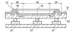
図1を参照する。図1は、本実施形態に係る車載機器操作システム100の全体構成を示す図である。(Structure of Embodiment)
See FIG. FIG. 1 is a diagram showing an overall configuration of an in-vehicle
本実施形態の車載機器操作システム100は、表示装置10と、制御装置20(車両用制御装置)と、例えば、自車両1のステアリングホイール3に設けられ、ユーザ(ここでは自車両1の運転席にいる運転者とする)が指(手)で操作可能な操作入力装置30と、を備える。車載機器操作システム100には、車両ECU201、ナビ(ナビゲーション)ECU202、オーディオECU203、空調ECU204、情報通信機器205等の電子機器200が、I/Oインタフェース210を介して、情報を授受可能に接続されている。 The in-vehicle
表示装置10は、自車両1のダッシュボード(図示しない)内に設けられたヘッドアップディスプレイ(HUD:Head−Up Display)装置である。HUD装置は、表示光をフロントウインドシールド2(被投影部材の一例である)に向けて出射し、仮想的な表示領域101内にメニュー画像500を表示することで、フロントウインドシールド2を介して視認される現実空間である前景に重ねてメニュー画像500を視認させる。 The
図1では、虚像として、メニュー画像500(V)が表示されている。なお、符号500(V)の「(V)」は、虚像であることを示している。ここで、ラジアル操作メニューとは、円の中心を基点に半径方向に延びる2本の線と、この2本の線の間の円弧で囲まれた、円を分割した部分円(セクタ領域)に、それぞれ項目を割り当てたメニュー形式をいう。ただし、ラジアル操作メニューは、所定の点を中心とした、円軌道上、楕円軌道上、矩形などの多角形軌道上に、複数の項目(アイコンなども含む)が配列されたメニュー形式も含んでもよい。 In FIG. 1, a menu image 500 (V) is displayed as a virtual image. In addition, "(V)" of reference numeral 500 (V) indicates that it is a virtual image. Here, the radial operation menu consists of two lines extending in the radial direction from the center of the circle and a partial circle (sector area) that divides the circle surrounded by an arc between the two lines. , Refers to the menu format to which each item is assigned. However, the radial operation menu may include a menu format in which multiple items (including icons) are arranged on a polygonal orbit such as a circular orbit, an elliptical orbit, or a rectangle centered on a predetermined point. good.
また、符号520は、ユーザの指(手)の動き(操作入力装置30が検出する)に応じて位置が変化するポインタ520(ここでは、時計の針のように、時計回りあるいは反時計回りに移動する)である。このポインタ520は、メニュー画像500(V)に含まれる複数の項目のうちの1つを指定する機能を有する。 Further,
また、表示装置10は、ヘッドマウントディスプレイ(以下、HMD)装置であってもよい。運転者は、HMD装置を頭部に装着して自車両1の座席に着座することで、表示されるメニュー画像500を、自車両1のフロントウインドシールド2を介した前景300に重畳して視認する。表示装置10が所定のメニュー画像500を表示する表示領域101は、自車両1の座標系を基準とした特定の位置に固定され、運転者がその方向を向くと、その特定の位置に固定された表示領域101内に表示されたメニュー画像500を視認することができる。 Further, the
なお、表示装置10は、インストルパネル内又はインストルパネル上に設けられる表示パネル等の表示器であってもよく、HUD装置、HMD装置、及び表示器が併用されてもよい。 The
説明を図1に戻す。電子機器200(車両ECU201、ナビECU202、オーディオECU203、空調ECU204、情報通信機器205)は、電子機器に関する情報を、I/Oインタフェース210を介して車載機器操作システム100に送信する。 The explanation is returned to FIG. The electronic device 200 (
ここで、車両ECU201は、自車両1の走行モード(ECOモード、SPORTモード)、平均燃費、走行可能距離(航続可能距離)、水温、油温などを送信可能である。後述する制御装置20は、受信した前記情報に基づき、例えば、自車両1の走行モードを示す画像、選択されることで走行モードを変更可能とする画像(機器操作実行項目の一例)、又は/及び平均燃費、走行可能距離、水温、油温等を示す画像、等を後述するメニュー項目510として表示してもよい。 Here, the
ナビECU202は、次の分岐路の方向、及び分岐路までの距離に関する情報、自車両1の経路付近に位置するオススメの経由地に関する施設情報、このオススメの経由地を経由した場合にロスする時間などの情報を送信可能である。後述する制御装置20は、受信した前記情報に基づき、例えば、次の分岐路の方向及び分岐路までの距離を示す画像、オススメの経由地に関する施設情報を含む画像、経路案内のオン/オフを切り替え可能とする画像(機器操作実行項目の一例)、又は/及び経由地の設定する画像(機器操作実行項目の一例)、等を後述するメニュー項目510として表示してもよい。 The
オーディオECU203は、オススメの音楽に関する情報などを送信可能である。後述する制御装置20は、受信した前記情報に基づき、例えば、オススメの音楽(オーディオ)に関する情報を含む画像、楽曲を選択可能な画像(機器操作実行項目の一例)、等を後述するメニュー項目510として表示してもよい。 The audio ECU 203 can transmit information about recommended music and the like. Based on the received information, the
空調ECU204は、現在の空調状態に関する情報等を送信可能である。後述する制御装置20は、受信した前記情報に基づき、例えば、現在の空調状態に関する情報を示す画像、空調状態を変更可能とする画像(機器操作実行項目の一例)、等を後述するメニュー項目510として表示してもよい。 The
情報通信機器205は、着信状態やメール受信情報など、自車両1の外部からの情報を送信可能である。後述する制御装置20は、受信した前記情報に基づき、例えば、着信があること、メール受信があることを示す画像、電話を受話する又はメールを音声で読ませることが可能な画像(機器操作実行項目の一例)、等を後述するメニュー項目510として表示してもよい。 The information communication device 205 can transmit information from the outside of the
次に、図2A、図2Bを参照して、操作入力装置30の構成を説明する。図2Aは、操作入力装置30の正面図であり、図2Bは、図2Aにおけるb−b線における断面構造を示す図である。ここでは、操作入力装置30が、図1において示したメニュー画像500におけるメニュー項目510(図3参照)を選択することに用いられることを想定して説明する。 Next, the configuration of the
操作入力装置30は、ユーザの親指等が操作面に触れた位置(操作位置C)を検出するタッチセンサであり、図2Bに示すように、表面カバー31と、センサシート32と、スペーサ33と、を備える。操作入力装置30は、ユーザが、親指等でその操作面上を触れる操作(以下、タッチ操作という)あるいは所定の軌跡を描くようになぞる操作(以下、ジェスチャ操作という)を行った際に、ユーザの親指等が操作面に触れている位置(操作位置C)を検出して、操作位置Cを示す信号(位置信号)を出力し、ユーザによる選択(決定)がなされると、その選択(決定)を検出して、例えば、選択(決定)がなされたことを示す信号(選択信号、言い換えれば選択(決定)検出信号)を出力する。 The
操作入力装置30における表面カバー31は、合成樹脂等の遮光性の絶縁材料によってシート状に形成され、凸状断面の立体形状が、中心点Qを中心とする円の円周に沿って断続的に形成された凸部(凸領域)34(図2Aにおいて、放射状の模様が付された領域)と、凸部(凸領域)34に連接する比較的平坦な平坦部(平坦領域)35と、を有する。凸部(凸領域)34は、山状の断面(凸状断面)を有し、その山(凸形状)は、中心点Qに向かう方向(内側)に長く、その反対方向である外側に短い輪郭線(稜線)を有する。その山(凸形状)が、中心点Qを中心とする円の円周に沿って、断続的に設けられることで凸部(凸領域)34が構成される。 The surface cover 31 of the
また、図2Bに記載されるように、表面カバー31における凸部(凸領域)34の下には、センサシート32が設けられており、これらを含む部分によって、上記の操作位置検出部36が構成される。ユーザは、例えば、上記の凸部(凸領域)34の、長手方向(中心点Qに向かう方向であり、言い換えれば内側方向)の斜面を指の触感で認識することにより、操作位置検出部36上における指のおおよその位置を認識することができ、操作入力装置30を見なくても、操作入力装置30を操作することができる。言い換えれば、ブラインド操作が可能となる。なお、上記の凸部(凸領域)34が設けられない場合も想定され得るが、この場合でも、ユーザが、中心点Qを中心とした円の円周に沿って手(指)の位置を移動させた場合、ユーザは、自身が移動させた手(指)の軌跡(指等がタッチセンサの操作面に接触した位置の時間的変遷の跡)を知覚できることから、ユーザは、自身の手の位置が、円の円周上のおおよそどの位置にあるかの見当をつけることができる。したがって、この場合でも、ブラインド操作が可能である。 Further, as shown in FIG. 2B, a
センサシート32は、少なくとも凸部(凸領域)34に対応する表面カバー31の裏面側において、中心点Qを中心とする円の円周に沿って配設され、ユーザの指の操作位置Cを検出して、制御装置20(車両用表示制御装置21)に、ユーザの指等の操作位置Cに関する情報(操作位置の情報、あるいは操作位置を示す信号)を出力する。センサシート32は、例えば、絞り加工により表面カバー31と一体成形されることで、表面カバー31と同様の形状に加工される(図2B参照)。このように一体成形されることで、表面カバー31とセンサシート32は、一枚のシートのようになり、上記の凸部(凸領域)34の段差形状は、その一枚のシートの曲がった部分(盛り上がった部分)で構成されることになる。また、このように一体成形されることで、表面カバー31の裏面とセンサシート32の表面とが当接する。これにより、表面カバー31の段差形状に対応して、センサシート32の検出部が配置されることになる。このように表面カバー31の段差形状に対応してセンサシート32の検出部が配置されているため、ユーザの指等の移動が、凸部(凸領域)34等の段差形状を有した操作面上で行われるものであっても、例えば車両用表示制御装置21が、ユーザの指の位置を検出することが可能である。 The
スペーサ33は、センサシート32の裏面側に位置し、一体成形された表面カバー31とセンサシート32の形状に合わせて形成され、ユーザの指等によって、表面カバー31が表側から押圧された際に、上記の形状を保持する部材である。 The
決定操作検出部37は、操作位置検出部36の裏面側に複数(図2Bの例では5個)設けられる。決定操作検出部37は、制御装置20(車両用表示制御装置21を含む)と電気的に接続されており、ユーザが、操作位置検出部36の操作面(表面カバー31の凸部(凸領域))34を押下する操作(以下、押下操作という)を行うと、決定操作検出部37が押され、これによって、ユーザによって選択(決定)がなされたことが検出され、選択(決定)がなされたことを示す信号(選択信号、言い換えれば選択(決定)検出信号)が出力される。出力された選択(決定)検出信号は、制御装置20(車両用表示制御装置21を含む)に送られる。車両用表示制御装置21は、送られてきた選択(決定)検出信号に基づき、例えば、メニュー画像500に含まれる複数のメニュー項目510のうちのどのメニュー項目510が選択されたかを判定し、その選択に応じた操作メニュー画像を生成し、表示装置10に表示する。これによって、選択されたメニュー項目510の内容に応じて、操作メニューの表示が切り替えられる。 A plurality of determination operation detection units 37 (five in the example of FIG. 2B) are provided on the back surface side of the operation
リターンスイッチ38は、操作位置検出部36及び決定操作検出部37とは離れた位置にあるスイッチである。ユーザが、リターンスイッチ38の操作面を押下する(言い換えれば、押下操作がなされる)と、制御装置20内の車両用表示制御装置21にリターン信号が送信される。車両用表示制御装置21は、リターンスイッチ38からのリターン信号に基づき、メニュー画像500の表示を、直近の過去の操作メニュー画像に戻す。言い換えれば、直前の表示への切り替えが行われる。 The
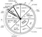
次に、図3を用いて、表示装置10に表示されるメニュー画像500の詳細について説明する。いくつかの実施形態に係る、メニュー画像500は、ラジアルメニューである。ラジアルメニューは、開図形又は閉図形上に、複数のメニュー項目510を連続的又は断続的に配列したものである。ラジアルメニューは、例えば、円の中心を基点に半径方向に延びる2本の線と、この2本の線の間の円弧で囲まれた、円を分割した部分円(セクタ領域)を連続的に円周方向に配列し、それぞれの部分円に項目を割り当てたメニュー形式である。なお、以下の説明において、制御装置20が、電子機器200の制御状態に関わる情報を取得あるいは検索し、この取得あるいは検索した情報を画像としてメニュー画像500を構成する部分円(セクタ領域)に割り当てたアイコン画像をメニュー項目510と称して説明し、ユーザの指(手)の動き(操作入力装置30が検出する)に応じて位置が変化する指定画像520をポインタと称して説明する。 Next, the details of the
メニュー項目510は、セクタ領域に区画された表示領域を有する画像であり、初期表示モードとして、例えば、図3に示すように、円の中心点Pを基点に円周方向に連続的に配列される。本実施形態の車載機器操作システム100では、メニュー項目510として、階層項目511と、機器操作実行項目512と、表示項目513と、が表示されるようになっている。 The
階層項目511は、操作する電子機器200の種類(例えば、「AIR CONTROL」)や制御状態を示す情報(例えば、設定温度「28℃」)などが区画された表示領域(部分円またはセクタ領域)内に表示された画像であり、この階層項目511を、操作入力装置30の操作により選択することで、例えば、空調装置の風量,風向き、温度設定など、が指定された新しい複数の階層項目511(新しいメニュー項目510)を含む新たなメニュー画像500の画像を表示する階層表示モードへ移行させることが可能である。
例えば、空調ECU204に関連する階層項目511を、操作入力装置30の操作により指定した場合、表示装置10の表示は、階層表示モードに移行する。階層表示モードで表示されるメニュー項目510としては、空調ECU204に関する空調装置の風量,風向きに関する機器操作実行項目等が表示される(階層表示モード)。風量,風向きに関する機器操作実行項目512を選択することで、空調装置の風量,風向きを変更することができ、温度設定に関する階層項目511を選択することで温度設定に関する階層表示モードに移行することができる。 For example, when the
機器操作実行項目512は、電子機器200を制御する項目(例えば、「ABS」)や設定値などが表示された画像であり、この機器操作実行項目512を、操作入力装置30の操作により選択することで、表示された項目や設定値に合わせて電子機器200に各種処理を実行させることが可能である。具体的に、例えば、「TCS」などを操作入力装置30により選択することで、車両ECU201に対してTCS機能のオンオフ処理を実行させることができる。 The device
なお、選択(決定)された機器操作実行項目512は、選択されたことを示すように色や形状が変化した表示態様J2aで表示され、選択(決定)されたことをユーザに認識させてもよい。 The selected (determined) device
表示項目513は、例えば、車両ECU201から入力される車両情報(例えば、水温、油温)などを区画された表示領域内に表示した画像であり、ユーザに情報を伝達するための画像である。この表示項目513を、操作入力装置30の操作により選択することで、表示された情報の詳細情報を表示させることが可能である。 The
表示項目513の区画された表示領域(部分円またはセクタ領域)内に表示される情報は、車両ECU201から出力される各種センサ情報(例えば、水温、油温等)に関わる情報,自車両1の各種設定(例えば、ABS,TCS,ECSなどの機能オンオフ、ECOモード、SPORTモードなどの走行モード)に関わる情報、ナビECU202から出力されるナビ情報(例えば、到着時間,目標地点までの距離,ターンバイターン等)に関わる情報、オーディオECU203の再生時間,曲名などを示す情報、空調ECU204の設定(例えば、温度設定、風量、風向など)を示す情報、情報通信機器205に接続された電子機器200の制御状態を示す情報(例えば、着信の有無、メール内容)などの、制御装置20が電子機器200から取得/検索した情報である。これら制御装置20が連続的または断続的に電子機器200から取得/検索した情報によってメニュー項目510内の表示が更新される。 The information displayed in the partitioned display area (partial circle or sector area) of the
また、メニュー項目510は、制御装置20が電子機器200から取得/検索した情報に関する画像のみならず、制御装置20自身が生成する情報に基づく画像であってもよい。具体的に、例えば、制御装置20が計時機能を有している場合、メニュー項目510としてストップウォッチ画像を表示してもよい。また、表示装置10が計時機能を有している場合、制御装置20が表示装置10の計時機能を実行して、表示装置10にメニュー項目510としてストップウォッチ画像を表示させてもよい。 Further, the
また、図3のメニュー項目510は、選択可能幅Wを有する。選択可能幅Wは、操作入力装置30の操作で、そのメニュー項目510を指定可能な位置信号Cの幅である。すなわち、選択可能幅Wが大きいメニュー項目510は、指定可能な位置信号Cの幅が広く、指定しやすくなる。複数のメニュー項目510の選択可能幅Wは、全て同じであってもよいが、メニュー項目510毎に異なる選択可能幅Wを有していてもよい。また、選択可能幅Wは、操作入力装置30での操作の仕方、自車両1の状態、電子機器200の状態、自車両1の運転者(又は運転者以外の乗員)の状態、又はこれらの組み合わせによって、適宜変更されてもよい。 Further, the
ポインタ520は、円の中心点Pを基点としてメニュー項目510側に延在して、操作入力装置30による操作位置Cで指定されるメニュー項目510(指定メニュー項目515)を指定する指針を示す画像であり、操作入力装置30の操作位置C(図2A参照)の移動に応じて、滑らかに指示位置Dを変化させ、指定メニュー項目515を切り替えるものである。ユーザ(運転者等)は、このポインタ520を視認することによって、操作入力装置30の操作で指定しているメニュー項目510(指定メニュー項目515)を確認することが可能である。なお、ポインタ520は、指定メニュー項目515の外郭を強調表示するカーソル指定画像521や、指定メニュー項目515の外側から指示するポインタ指定画像522、指定メニュー項目515の色の変化、指定されていないメニュー項目510(指定メニュー項目515以外のメニュー項目)の色の変化、指定メニュー項目515の拡大、指定されていないメニュー項目510(指定メニュー項目515以外のメニュー項目)の縮小、などで代替してもよく、これらの組み合わせであってもよい。 The
次に、図4を参照して本実施形態の制御装置20のより具体的な構成について説明する。ここで、制御装置20は、車両用表示制御装置21と、動作実行装置25と、を含む構成をいう。なお、図4において、図1と共通する部分については同じ符号が示されている。 Next, a more specific configuration of the
車両用表示制御装置21は、1つ又はそれ以上のプロセッサ22、メモリ23、及び画像処理回路24を備える。図4は、実施態様の一実施例に過ぎず、図示された構成要素は、より数の少ない構成要素に組み合わされてもよく、又は追加の構成要素があってもよい。例えば、画像処理回路24(例えば、グラフィック処理ユニット)が、1つ又はそれ以上のプロセッサ22に含まれてもよい。また、プロセッサ22が、後述する動作実行装置25の一部又は全部の機能を有していてもよい。 The vehicle
図示するように、プロセッサ22及び画像処理回路24は、メモリ23と動作可能に連結される。より具体的には、プロセッサ22及び画像処理回路24は、メモリ23に記憶されているプログラムを実行することで、例えば画像データを生成又は/及び送信するなど、表示装置10の操作を行うことができる。プロセッサ22又は/及び画像処理回路24は、少なくとも1つの汎用マイクロプロセッサ(例えば、中央処理装置(CPU))、少なくとも1つの特定用途向け集積回路(ASIC)、少なくとも1つのフィールドプログラマブルゲートアレイ(FPGA)、又はそれらの任意の組み合わせを含むことができる。メモリ23は、ハードディスクのような任意のタイプの磁気媒体、CD及びDVDのような任意のタイプの光学媒体、揮発性メモリのような任意のタイプの半導体メモリ、及び不揮発性メモリを含む。揮発性メモリは、DRAM及びSRAMを含み、不揮発性メモリは、ROM及びNVROMを含んでもよい。 As shown, the
図示するように、プロセッサ22は、I/Oインタフェース210と動作可能に連結されている。例えば、I/Oインタフェース210は、USBポート、シリアルポート、パラレルポート、OBDII、及び/又は他の任意の適切な有線通信ポートなどを有し、CAN(Controller Area Network)、Ethernet(登録商標)などに接続する有線通信インタフェースを含むことができる。また、I/Oインタフェース210は、Bluetooth(登録商標)ネットワークなどのパーソナルエリアネットワーク(PAN)、802.11x Wi−Fi(登録商標)ネットワークなどのローカルエリアネットワーク(LAN)、4G又はLTE(登録商標)セルラーネットワークなどの広域ネットワーク(WAN)に接続する無線通信インタフェースを含むことができる。 As shown, the
図示するように、プロセッサ22は、I/Oインタフェース210と相互動作可能に連結されることで、車両用表示制御装置21に接続される種々の電子機器200と情報を授受可能となる。I/Oインタフェース210には、例えば、車両ECU201、ナビECU202、オーディオECU203、空調ECU204、情報通信機器205、及び自車両1に設けられた図示しないギアポジションセンサ、ブレーキセンサ、速度センサ、加速度センサ、アクセルセンサなどのセンサなどが情報を授受可能に連結される。表示装置10は、プロセッサ22及び画像処理回路24に動作可能に連結される。したがって、表示装置10によって表示される画像は、プロセッサ22又は/及び画像処理回路24から受信された画像データに基づいてもよい。プロセッサ22及び画像処理回路24は、I/Oインタフェース210から得られる情報に基づき、表示装置10が表示する画像を制御する。なお、I/Oインタフェース210は、表示装置10に接続される他の電子機器等から受信する情報を加工(変換、演算、解析)する機能を有していてもよい。 As shown in the figure, the
制御装置20におけるプロセッサ22、及び動作実行装置25は、メニュー画像500に含まれる一つの項目を指定するために、ユーザが操作入力装置30の操作面上を触れるタッチ操作あるいは所定の軌跡を描くようになぞるジェスチャ操作に応じて生成される位置信号C、及び押下するユーザ操作に応じて生成される選択(決定)信号を、操作入力装置30から入力する。 The
車両用表示制御装置21における画像処理回路24は、メニュー画像500の画像を生成する。例えば、予め用意されている複数のメモリ23の中から使用可能なものを取り出し(読み出し)、必要な情報を画像合成で組み込むことで、複数のメニュー項目510を含むメニュー(操作メニュー)の画像を生成する。但し、これに限定されるものではなく、メモリ23に予め記憶された配列、又はメモリ23に記憶されたプログラムにより定められた配列に従って、複数の項目を配置する(項目を画像合成する)ことで、メニュー(メニュー項目)の画像を生成してもよく、あるいは、レンダリングにより画像を生成してもよい。生成された画像は、画像RAM(不図示)等に、一旦、蓄積される。 The
なお、車両用表示制御装置21は、電子機器200(車両ECU201、ナビECU202、オーディオECU203、空調ECU204、情報通信機器205)からの情報を使用して画像を生成することができ、あるいは、その情報を使用せずに、メモリ23に予め記憶された画像データのみに基づき画像を生成してもよい。これによって、例えば、図1で示したメニュー画像500の元となる画像(元画像)を生成することができる。 The vehicle
表示されるメニュー画像500は、階層構造を有しており、選択された1つの項目に関連付けされた下位階層のメニューがある場合は、その下位階層のメニューが順次、表示される。下位階層のない項目(機器操作実行項目512)が選択されると、例えば、画像処理回路24から動作実行装置25に、最終的に選択された項目の内容を示す情報が送られる。動作実行装置25は、例えば、機器動作ファイル26を参照して、実行すべき処理の具体的な内容を示すデータを取得し(但し、この動作は不要な場合もあり得る)、取得したデータを、I/Oインタフェース210を経由して、電子機器200に送る。これによって、ユーザによって選択された項目に関連付けられている処理が実行される。 The displayed
メモリ23に記憶されたソフトウェア構成要素は、プロセッサ22又は/及び画像処理回路24が、画像(メニュー画像500を含む)を生成するためグラフィックモジュール(図示しない)を含む。グラフィックモジュールは、表示されるメニュー画像500の、視覚的効果(例えば、輝度、透明度、彩度、コントラスト、又は他の視覚特性)、サイズ、表示位置、表示距離(運転者4からメニュー画像500までの距離)を変更するための様々な既知のソフトウェア構成要素を含む。グラフィックモジュールは、メニュー画像500の少なくとも一部の視認性を、操作入力装置30から取得した操作位置Cに応じて変化させる。このメニュー画像500の視認性を変化させる表示制御については、後で詳述する。 The software component stored in the
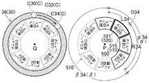
次に、図5A〜図5Cを参照して、メニュー画像500の視認性を変化させる表示制御について説明する。図5A〜図5Cにおける、左図は、メニュー画像500に含まれるメニュー項目510と操作入力装置30での操作位置Cとの対応関係を仮想的に示す図であり、右図は、左図での操作位置Cを入力した際の表示装置10が表示するメニュー画像500の様子を示す図である。なお、ここでは、メニューの画像は、ラジアルメニューであるものとする(但し、これらは一例であり、これらの例に限定されるものではない)。 Next, the display control for changing the visibility of the
図5A(図5B、図5Cでも同様)の左図の例では、操作入力装置30の操作位置検出部36が、中心点Qを基準とした円(閉図形の一例)上に配置され、中心点Qを基準とした操作位置(角度位置でも代替え可能)を車両用表示制御装置21に送信する。なお、操作位置検出部36の操作位置Cとメニュー画像500のメニュー項目510との位置関係を把握しやすくするために、図5A(図5B、図5C)の左図では、便宜上、操作位置検出部36の内側に、仮想的にメニュー項目510を記載してある。図5A(図5B、図5Cでも同様)のラジアルメニューの例では、全周を8等分したメニュー項目510で構成される(1項目当たり45[degree])。図5Aの中心点Qからの直上方向を、0[degree]とすると、メニュー画像500は、−22.4(337.6)〜22.5[degree]の領域に配置される「メニュー項目A」、22.6〜67.5[degree]の領域に配置される「メニュー項目B」、67.6〜112.5[degree]の領域に配置される「メニュー項目C」、112.6〜157.5[degree]の領域に配置される「メニュー項目D」、157.6〜202.5[degree]の領域に配置される「メニュー項目E」、202.5〜247.5[degree]の領域に配置される「メニュー項目F」、247.6〜292.5[degree]の領域に配置される「メニュー項目G」、及び292.6〜337.5[degree]の領域に配置される「メニュー項目H」、で構成される。 In the example on the left of FIG. 5A (the same applies to FIGS. 5B and 5C), the operation
前記グラフィックモジュールを実行することで、1つ又はそれ以上のプロセッサ22は、操作入力装置30から取得した操作位置C(図5Aの左図参照)に対応した指示位置D(図5Bの右図参照)を含むメニュー項目510を指定する。また、1つ又はそれ以上のプロセッサ22は、操作位置Cに対応した指示位置D(図5Aの右図参照)を含む所定範囲の表示領域αを設定し、設定した所定範囲の表示領域αに割り当てられるメニュー項目510の少なくとも一部を第1の視認性で表示させ、所定範囲の表示領域αに割り当てられていない(表示領域βに割り当てられている)メニュー項目510を、第1の視認性より低い第2の視認性で表示させる。 By executing the graphic module, one or
図5Aでは、1つ又はそれ以上のプロセッサ22は、操作入力装置30から操作位置C10(0[degree])を取得し、この操作位置C10に対応した指示位置D10を含む「メニュー項目A」を指定する(「メニュー項目A」の外郭にカーソル指定画像521を表示する)。また、1つ又はそれ以上のプロセッサ22は、操作位置C10に対応した指示位置D10を基準にした第1方向(図5AのCCW(CounterClockWise))の表示領域L10と、第1方向とは逆の第2方向(図5AのCW(ClockWise))の表示領域R10と、を設定し、設定した第1方向の表示領域L10と第2方向の表示領域R10とを含む所定範囲の表示領域α10に割り当てられるメニュー項目510の部分を第1の視認性で表示させ、所定範囲の表示領域α10に割り当てられていない(表示領域β10に割り当てられている)メニュー項目510の部分を、第1の視認性より低い第2の視認性で表示させる。図5Aの右図において、実線のメニュー項目510の部分は、第1の視認性で表示され、点線のメニュー項目510の部分は、第2の視認性で表示される。具体的には、第1方向の表示領域L10及び第2方向の表示領域R10は、それぞれ45[degree]であり、所定範囲の表示領域α10は、90[degree]であり、メニュー画像500の25%を占める。換言すると、メニュー画像500のうち、指示位置Dを中心とした全体の25%の表示領域は、第1の視認性で表示され、他の75%は、第1の視認性より低い第2の視認性で表示される。 In FIG. 5A, one or
図5Bでは、1つ又はそれ以上のプロセッサ22は、操作位置C20に対応した指示位置D20を基準にした第1方向の表示領域L20と、第2方向の表示領域R20と、を設定し、設定した第1方向の表示領域L20と第2方向の表示領域R20とを含む所定範囲の表示領域α20に一部分でも割り当てられるメニュー項目510を第1の視認性で表示させ、所定範囲の表示領域α20に一部分も割り当てられていない(全体が表示領域β20に割り当てられている)メニュー項目510の部分を、第1の視認性より低い第2の視認性で表示させる。図5Bの右図において、実線のメニュー項目510の部分は、第1の視認性で表示され、点線のメニュー項目510の部分は、第2の視認性で表示される。具体的には、第1方向の表示領域L20及び第2方向の表示領域R20は、それぞれ45[degree]であり、所定の表示領域α20は、315〜45[degree]の90[degree]の範囲である。315〜45[degree]からなる所定の表示領域α20に、−22.4(337.6)〜22.5[degree]の領域に配置される「メニュー項目A」の全体、22.6〜67.5[degree]の領域に配置される「メニュー項目B」の一部分、292.6〜337.5[degree]の領域に配置される「メニュー項目H」の一部分が含まれるため、プロセッサ22は、「メニュー項目A」、「メニュー項目B」、及び「メニュー項目H」を第1の視認性で表示し、それ以外の「メニュー項目C」、「メニュー項目D」、「メニュー項目E」「メニュー項目F」、及び「メニュー項目G」を第2の視認性で表示する。 In FIG. 5B, one or
図5Cは、操作入力装置30から入力される操作位置Cが、C30からC32、C34の順に速く移動した場合の表示例を示す。1つ又はそれ以上のプロセッサ22は、操作入力装置30から位置信号Cの変化速度、若しくは位置信号Cの変化加速度を取得する、又は操作入力装置30から取得した位置信号Cから変化速度、若しくは変化加速度を推定し、位置信号Cが第1方向(又は第2方向)に所定の閾値より大きい変化速度又は変化加速度で変化した場合、位置信号Cを基準にした第1方向の表示領域L(第2方向の表示領域R)を、第2方向の表示領域R(第1方向の表示領域L)より大きくする。1つ又はそれ以上のプロセッサ22は、操作位置C34に対応した指示位置D34を基準にした第1方向の表示領域L34と、第2方向の表示領域R34と、を設定し、設定した第1方向の表示領域L34と第2方向の表示領域R34とを含む所定範囲の表示領域α34に一部分でも割り当てられるメニュー項目510を第1の視認性で表示させ、所定範囲の表示領域α34に一部分も割り当てられていない(全体が表示領域β34に割り当てられている)メニュー項目510の部分を、第1の視認性より低い第2の視認性で表示させる。操作入力装置30からの操作位置Cが、第2方向(図5CのCW)にC30からC32、C34の順に速く移動した場合、1つ又はそれ以上のプロセッサ22は、第2方向の表示領域Rを大きくする。具体的には、第2方向の表示領域Rを通常の45[degree](メニュー画像500の12.5%)から、90[degree](メニュー画像500の25%)に大きくしている。これにより、所定範囲の表示領域α34は、通常であれば、指示位置D34を中心とした90[degree](メニュー画像500の25%)であるが、操作位置Cが速く変化したことで、135[degree](メニュー画像500の37.5%)に拡大する。 FIG. 5C shows a display example in which the operation position C input from the
図6は、いくつかの実施形態に係る、車載機器操作システムにおける表示制御のプロセスを示すフロー図である。 FIG. 6 is a flow chart showing a display control process in an in-vehicle device operation system according to some embodiments.
車両用表示制御装置21は、操作入力装置30から位置信号Cを取得する(ステップS1)。これに加えて、ステップS1では、車両用表示制御装置21は、操作入力装置30から位置信号Cの変化速度、若しくは位置信号Cの変化加速度を取得する、又は操作入力装置30から取得した位置信号Cから変化速度、若しくは変化加速度を推定してもよい。 The vehicle
次に、ステップS2において、車両用表示制御装置21は、自車両1の状態を取得する。 Next, in step S2, the vehicle
車両用表示制御装置21は、所定範囲の表示領域αを、位置信号Cに対応する指示位置Dを中心に設定する、又は、位置信号Cの移動方向に応じて、位置信号Cを基準にした第1方向の表示領域Lと、第1方向とは逆の第2方向の表示領域Rとをそれぞれ設定する(ステップS3)。例えば、位置信号Cが第1方向に移動した場合、位置信号Cを基準にした第1方向の表示領域Lを、第2方向の表示領域Rより大きくしてもよい。なお、これらに加えて、ステップS2で取得した自車両1の状態に応じて、所定範囲の表示領域α(又は第1方向の表示領域L、及び第2方向の表示領域R)を調整してもよい。具体的には、車両用表示制御装置21は、自車両1が停止していると推測できる場合、所定範囲の表示領域α(第1方向の表示領域L、及び第2方向の表示領域R)を大きくしてもよい。 The vehicle
車両用表示制御装置21は、所定範囲の表示領域αに少なくとも一部分が割り当てられるメニュー項目510を第1の視認性で表示させ、所定範囲の表示領域αに割り当てられていないメニュー項目510を、第1の視認性より低い第2の視認性で表示させる(ステップS4)。 The vehicle
車両用表示制御装置21は、所定範囲の表示領域αから外れた経過時間が所定の時間より長くなったか判定する。言い換えると、第1の視認性で表示する対象から外れてからの経過時間が所定の時間より長くなったか判定する(ステップS5)。経過時間が所定の時間より長くなければ(ステップS5でNO)、処理を終了し、再びステップS1から処理を開始する。 The vehicle
経過時間が所定の時間より長くなった場合(ステップS5でYES)、車両用表示制御装置21は、第1の視認性で表示する対象から外れてからの経過時間が所定の時間より長くなった領域を、第1の視認性から第2の視認性に変化させる。これにより、急に表示領域の視認性が低下することを防止することができる。なお、車両用表示制御装置21は、第1の視認性から第2の視認性へ変化させる際、徐々に視認性を低下させていってもよい。 When the elapsed time is longer than the predetermined time (YES in step S5), the vehicle
図6におけるプロセスについて説明された特定の順序は例示であり、説明された順序は、プロセスを実行することができる唯一の順序であることを示すことを意図するものではないことを理解されたい。当業者であれば、本明細書で説明される動作の再順序付け、一部追加、又は/及び一部削除をする様々な変更を加えることができるであろう。 It should be understood that the particular order described for the process in FIG. 6 is exemplary and the order described is not intended to indicate that it is the only order in which the process can be executed. One of ordinary skill in the art will be able to make various changes to reorder, partially add, or / and partially delete the operations described herein.
上述の情報処理プロセスの動作は、汎用プロセッサ又は特定用途向けチップなどの情報処理装置の1つ以上のソフトウエアモジュールを実行させることにより実施することができる。これらのモジュール、これらのモジュールの組み合わせ、又は/及びそれらの機能を代替えし得る一般的なハードウェアとの組み合わせは全て、本発明の保護の範囲内に含まれる。 The operation of the above-mentioned information processing process can be carried out by executing one or more software modules of an information processing device such as a general-purpose processor or a chip for a specific purpose. All of these modules, combinations of these modules, and / or combinations with common hardware that can replace their functionality are within the scope of the protection of the present invention.
車載機器操作システム100の機能ブロックは、任意選択的に、説明される様々な実施例の原理を実行するために、ハードウェア、ソフトウェア、又はハードウェア及びソフトウェアの組み合わせによって実行される。図1、図4で説明する機能ブロックが、説明される実施例の原理を実施するために、任意選択的に、組み合わされ、又は1つの機能ブロックを2以上のサブブロックに分離されてもいいことは、当業者に理解されるだろう。したがって、本明細書における説明は、本明細書で説明されている機能ブロックのあらゆる可能な組み合わせ若しくは分割を、任意選択的に支持する。 The functional blocks of the in-vehicle
以上に説明したように、本実施形態では、操作入力装置30から取得した位置信号に応じてポインタ520が指定するメニュー項目510(指定メニュー項目515)を変化させ、操作入力装置30から取得した位置信号が示す位置を含む所定範囲の表示領域αを設定し、設定された所定範囲の表示領域αに割り当てられるメニュー項目510の少なくとも一部を第1の視認性で表示させ、所定範囲の表示領域αに割り当てられていないメニュー項目510を、第1の視認性より低い第2の視認性で表示させる。 As described above, in the present embodiment, the menu item 510 (designated menu item 515) designated by the
また、いくつかの実施形態では、所定範囲の表示領域αに割り当てられるメニュー項目510の少なくとも一部を第1の視認性で表示させる命令は、所定範囲の表示領域αに一部でも含まれるメニュー項目510を第1の視認性で表示させてもよい。 Further, in some embodiments, a command for displaying at least a part of the
また、いくつかの実施形態では、所定範囲の表示領域αは、位置信号を基準にした第1方向の表示領域Lと、第1方向とは逆の第2方向の表示領域Rと、を含んでもよい。 Further, in some embodiments, the display area α in the predetermined range includes a display area L in the first direction based on the position signal and a display area R in the second direction opposite to the first direction. It may be.
また、いくつかの実施形態では、操作入力装置30から取得した位置信号が示す位置を含む所定範囲の表示領域αを設定する命令では、位置信号が第1方向に移動した場合、位置信号を基準にした第1方向の表示領域Lを、第2方向の表示領域Rより大きくしてもよい。 Further, in some embodiments, in the command for setting the display area α of the predetermined range including the position indicated by the position signal acquired from the
また、いくつかの実施形態では、1つ又はそれ以上のコンピュータ・プログラムは、操作入力装置30から位置信号の変化速度、若しくは位置信号の変化加速度を取得する、又は操作入力装置30から取得した位置信号から変化速度、若しくは変化加速度を推定する命令をさらに含み、操作入力装置30から取得した位置信号が示す位置を含む所定範囲の表示領域αを設定する命令では、位置信号が第1方向に所定の閾値より大きい変化速度又は変化加速度で変化した場合、位置信号を基準にした第1方向の表示領域Lを、第2方向の表示領域Rより大きくし、位置信号が第1方向に所定の閾値より小さい変化速度又は変化加速度で変化した場合、位置信号を基準にした第1方向の表示領域Lを、第2方向の表示領域Rと等しくしてもよい。 Also, in some embodiments, one or more computer programs obtain the rate of change of the position signal or the rate of change of the position signal from the
また、いくつかの実施形態では、1つ又はそれ以上のコンピュータ・プログラムは、車両の状態を取得する命令をさらに含み、操作入力装置30から取得した位置信号が示す位置を含む所定範囲の表示領域αを設定する命令では、車両の状態に応じて、所定範囲の表示領域αの大きさを変えてもよい。 Also, in some embodiments, the one or more computer programs further include an instruction to acquire the state of the vehicle and a predetermined range of display areas including the position indicated by the position signal acquired from the
また、いくつかの実施形態では、車両の状態を取得する命令において、車両の状態は、車両の停止を示す情報、又は車両の停止を推定できる情報、を含み、操作入力装置30から取得した位置信号が示す位置を含む所定範囲の表示領域αを設定する命令では、車両が停止していると推測できる場合、所定範囲の表示領域αを大きくしてもよい。 Further, in some embodiments, in the command for acquiring the state of the vehicle, the state of the vehicle includes information indicating the stop of the vehicle or information capable of estimating the stop of the vehicle, and the position acquired from the
また、いくつかの実施形態では、車両の状態を取得する命令における車両の状態は、車両のギアポジション、ブレーキ状態、速度、加速度、及びアクセル状態の少なくとも1つを含んでもよい。 Also, in some embodiments, the vehicle state in the command to acquire the vehicle state may include at least one of the vehicle's gear position, braking state, speed, acceleration, and accelerator state.
また、いくつかの実施形態では、1つ又はそれ以上のコンピュータ・プログラムは、所定の表示領域αから外れた後の経過時間を計時する命令をさらに含み、所定範囲の表示領域αに割り当てられていないメニュー項目510を、第2の視認性で表示させる命令では、所定範囲の表示領域αに割り当てられていないメニュー項目510を、経過時間が所定の時間より長くなるまで第1の視認性を維持させてもよい。 Also, in some embodiments, one or more computer programs are allocated to a predetermined range of display areas α, further including instructions to time the elapsed time after leaving the predetermined display area α. In the command to display the missing
また、いくつかの実施形態では、所定範囲の表示領域αに割り当てられていないメニュー項目510を、第2の視認性で表示させる命令では、所定範囲の表示領域αに割り当てられていないメニュー項目510の一部を、背景の色と同じあるいは背景の色に近似する色にする、又は透過率を高くしてもよい。近似する色とは、RGB空間におけるR,G,Bの値の差分が±15%以下の範囲に属す色、または/およびHSV空間におけるH(色相),S(彩度),V(明度)の値の差分が±15%以下の範囲に属す色とする。プロセッサ22は、メニュー項目510の全体を、背景の色と同じにする必要はなく、一部であってもよく、メニュー項目510の全体の50%以上を、背景の類似色としてもよい。また、視認性は、例えば、画像の輝度(階調)の調整によって実現してもよく、明度、彩度、色調等を併せて調整することもできる。 Further, in some embodiments, the
図7は、いくつかの実施形態に係る、メニュー画像500の例を示す図である。図7のメニュー画像500では、複数のメニュー項目510が上下方向に配置されている。いくつかの実施形態では、メニュー項目510は、コンテンツ画像517と、コンテンツ画像517の周囲の塗り画像518と、を含んでいてもよい。所定範囲の表示領域αに割り当てられていないメニュー項目510を、第2の視認性で表示させる命令では、所定範囲の表示領域αに割り当てられていないメニュー項目510の塗り画像518の少なくとも一部を、図7に示すように、背景の色と同じあるいは背景の色に近似する色にする、又は透過率を高くしてもよい。また、コンテンツ画像517を、図7に示すように、中抜きにしてもよい。 FIG. 7 is a diagram showing an example of the
また、いくつかの実施形態では、車両用表示制御装置21が表示する複数のメニュー項目510は、開図形又は閉図形上に配列され、操作入力装置30から取得した位置信号に応じてポインタ520が指定メニュー項目515を変化させる命令では、位置信号に応じてポインタ520の位置を変化させてもよい。すなわち、メニュー画像500は、閉図形上にメニュー項目510を配列させるラジアルメニューでなくてもよい。 Further, in some embodiments, the plurality of
また、いくつかの実施形態では、車両用表示制御装置21が表示する複数のメニュー項目510は、運転者から見て上下方向、左右方向、又は任意の方向の直線、または曲線からなる開図形上に配列され、操作入力装置30から取得した位置信号に応じてポインタ520が指定するメニュー項目510(指定メニュー項目515)を変化させる命令では、位置信号に応じてポインタ520の位置を変化させもよい。すなわち、メニュー画像500は、上下方向、左右方向、又は任意の方向の直線、または曲線からなる開図形上にメニュー項目510を配置させる、これらメニュー項目510に対してポインタ520が操作に応じて動いてもよい。 Further, in some embodiments, the plurality of
また、いくつかの実施形態では、車両用表示制御装置21が表示する複数のメニュー項目510は、運転者から見て上下方向、左右方向、又は任意の方向の直線、または曲線からなる開図形上に配列され、操作入力装置30から取得した位置信号に応じてポインタ520が指定するメニュー項目515を変化させる命令では、ポインタ520を固定し、位置信号に応じて、ポインタ520が指定する位置に複数のメニュー項目510を移動させてもよい。すなわち、メニュー画像500は、上下方向、左右方向、又は任意の方向の直線、または曲線からなる開図形上にメニュー項目510を配置させ、ポインタ520を固定し、ポインタ520に対してメニュー項目510が操作に応じて動いてもよい。 Further, in some embodiments, the plurality of
1・・・自車両、2・・・フロントウインドシールド、3・・・ステアリングホイール、4・・・運転者、10・・・表示装置、20・・・制御装置、21・・・車両用表示制御装置、22・・・プロセッサ、23・・・メモリ、24・・・画像処理回路、25・・・動作実行装置、26・・・機器動作ファイル、30・・・操作入力装置、31・・・表面カバー、32・・・センサシート、33・・・スペーサ、36・・・操作位置検出部、37・・・決定操作検出部、38・・・リターンスイッチ、100・・・車載機器操作システム、101・・・表示領域、200・・・電子機器、210・・・I/Oインタフェース、500・・・メニュー画像、510・・・メニュー項目、511・・・階層項目、512・・・機器操作実行項目、513・・・表示項目、515・・・指定メニュー項目、517・・・コンテンツ画像、518・・・塗り画像、520・・・ポインタ(指定画像)、521・・・カーソル指定画像、522・・・ポインタ指定画像、C・・・操作位置(位置信号)、D・・・指示位置(指示信号)、L・・・第1方向の表示領域、P・・・中心、Q・・・中心点、R・・・第2方向の表示領域、1 ... own vehicle, 2 ... front windshield, 3 ... steering wheel, 4 ... driver, 10 ... display device, 20 ... control device, 21 ... vehicle display Control device, 22 ... Processor, 23 ... Memory, 24 ... Image processing circuit, 25 ... Operation execution device, 26 ... Equipment operation file, 30 ... Operation input device, 31 ... -Surface cover, 32 ... sensor sheet, 33 ... spacer, 36 ... operation position detection unit, 37 ... determination operation detection unit, 38 ... return switch, 100 ... in-vehicle device operation system , 101 ... Display area, 200 ... Electronic equipment, 210 ... I / O interface, 500 ... Menu image, 510 ... Menu item, 511 ... Hierarchical item, 512 ... Equipment Operation execution items, 513 ... Display items, 515 ... Designated menu items, 517 ... Content images, 518 ... Filled images, 520 ... Pointers (designated images), 521 ... Cursor designated
Claims (17)
Translated fromJapanese1つ又はそれ以上のプロセッサと、
メモリと、
前記メモリに格納され、前記1つ又はそれ以上のプロセッサによって実行されるように構成される1つ又はそれ以上のコンピュータ・プログラムと、を備え、
前記1つ又はそれ以上のコンピュータ・プログラムは、
前記操作入力装置から取得した前記位置信号に応じて前記ポインタが指定するメニュー項目を変化させ、
前記操作入力装置から取得した前記位置信号が示す位置を含む所定範囲の表示領域を設定し、
設定された前記所定範囲の表示領域に割り当てられる前記メニュー項目の少なくとも一部を第1の視認性で表示させ、
前記所定範囲の表示領域に割り当てられていないメニュー項目を、前記第1の視認性より低い第2の視認性で表示させる、
命令を含む、車両用表示制御装置。A vehicle display control device that controls the display of a plurality of menu items and a pointer that specifies the menu item, a display device that displays the menu item and the pointer, and a position of the pointer are specified according to a user operation. An operation input device that generates a position signal to be generated and a selection signal for selecting one included in the menu item, and an operation execution device that executes an operation process of an electronic device corresponding to the menu item selected by the user. The vehicle display control device used in the in-vehicle device operation system having the above.
With one or more processors
With memory
It comprises one or more computer programs stored in the memory and configured to be executed by the one or more processors.
The one or more computer programs mentioned above
The menu item specified by the pointer is changed according to the position signal acquired from the operation input device.
A display area in a predetermined range including the position indicated by the position signal acquired from the operation input device is set.
At least a part of the menu items allocated to the set display area of the predetermined range is displayed with the first visibility.
Menu items that are not assigned to the display area of the predetermined range are displayed with a second visibility lower than the first visibility.
Vehicle display control device, including instructions.
前記所定範囲の表示領域に一部でも含まれる前記メニュー項目を前記第1の視認性で表示させる、
請求項1に記載の車両用表示制御装置。The command for displaying at least a part of the menu items assigned to the display area of the predetermined range with the first visibility is
The menu item, which is partially included in the display area of the predetermined range, is displayed with the first visibility.
The vehicle display control device according to claim 1.
請求項1に記載の車両用表示制御装置。The display area in the predetermined range includes a display area in the first direction based on the position signal and a display area in the second direction opposite to the first direction.
The vehicle display control device according to claim 1.
前記位置信号が前記第1方向に移動した場合、前記位置信号を基準にした前記第1方向の表示領域を、前記第2方向の表示領域より大きくする、
請求項3に記載の車両用表示制御装置。In the command for setting the display area of the predetermined range including the position indicated by the position signal acquired from the operation input device, the command
When the position signal moves in the first direction, the display area in the first direction based on the position signal is made larger than the display area in the second direction.
The vehicle display control device according to claim 3.
前記操作入力装置から前記位置信号の変化速度、若しくは前記位置信号の変化加速度を取得する、又は
前記操作入力装置から取得した前記位置信号から前記変化速度、若しくは前記変化加速度を推定する命令をさらに含み、
前記操作入力装置から取得した前記位置信号が示す位置を含む前記所定範囲の表示領域を設定する命令では、
前記位置信号が前記第1方向に所定の閾値より大きい前記変化速度又は前記変化加速度で変化した場合、前記位置信号を基準にした前記第1方向の表示領域を、前記第2方向の表示領域より大きくし、
前記位置信号が前記第1方向に所定の閾値より小さい前記変化速度又は前記変化加速度で変化した場合、前記位置信号を基準にした前記第1方向の表示領域を、前記第2方向の表示領域と等しくする、
請求項3に記載の車両用表示制御装置。The one or more computer programs mentioned above
Further includes an instruction to acquire the change speed of the position signal or the change acceleration of the position signal from the operation input device, or to estimate the change speed or the change acceleration from the position signal acquired from the operation input device. ,
In the command for setting the display area of the predetermined range including the position indicated by the position signal acquired from the operation input device, the command
When the position signal changes in the first direction at the change speed or the change acceleration larger than a predetermined threshold value, the display area in the first direction based on the position signal is displayed from the display area in the second direction. Make it bigger
When the position signal changes in the first direction at the change speed or the change acceleration smaller than a predetermined threshold value, the display area in the first direction based on the position signal is referred to as the display area in the second direction. Make it equal
The vehicle display control device according to claim 3.
車両の状態を取得する命令をさらに含み、
前記操作入力装置から取得した前記位置信号が示す位置を含む前記所定範囲の表示領域を設定する命令では、
前記車両の状態に応じて、前記所定範囲の表示領域の大きさを変える、
請求項1に記載の車両用表示制御装置。The one or more computer programs mentioned above
Including an additional command to get the state of the vehicle,
In the command for setting the display area of the predetermined range including the position indicated by the position signal acquired from the operation input device, the command
The size of the display area in the predetermined range is changed according to the state of the vehicle.
The vehicle display control device according to claim 1.
前記車両の状態は、前記車両の停止を示す情報、又は前記車両の停止を推定できる情報、を含み、
前記操作入力装置から取得した前記位置信号が示す位置を含む前記所定範囲の表示領域を設定する命令では、
前記車両が停止していると推測できる場合、前記所定範囲の表示領域を大きくする、
請求項6に記載の車両用表示制御装置。In the command to acquire the state of the vehicle
The state of the vehicle includes information indicating the stop of the vehicle or information capable of estimating the stop of the vehicle.
In the command for setting the display area of the predetermined range including the position indicated by the position signal acquired from the operation input device, the command
When it can be estimated that the vehicle is stopped, the display area of the predetermined range is increased.
The vehicle display control device according to claim 6.
請求項7に記載の車両用表示制御装置。The vehicle state in the command to acquire the vehicle state includes at least one of the vehicle's gear position, braking state, speed, acceleration, and accelerator state.
The vehicle display control device according to claim 7.
前記所定の表示領域から外れた後の経過時間を計時する命令をさらに含み、
前記所定範囲の表示領域に割り当てられていないメニュー項目を、前記第2の視認性で表示させる命令では、
前記所定範囲の表示領域に割り当てられていないメニュー項目を、前記経過時間が所定の時間より長くなるまで前記第1の視認性を維持させる、
請求項1に記載の車両用表示制御装置。The one or more computer programs mentioned above
It further includes an instruction to time the elapsed time after leaving the predetermined display area.
In the command for displaying menu items not assigned to the display area in the predetermined range with the second visibility, the command is used.
Menu items that are not assigned to the display area of the predetermined range are maintained in the first visibility until the elapsed time becomes longer than the predetermined time.
The vehicle display control device according to claim 1.
前記所定範囲の表示領域に割り当てられていないメニュー項目の一部を、背景の色と同じあるいは背景の色に近似する色にする、又は透過率を高くする、
請求項1に記載の車両用表示制御装置。In the command for displaying menu items not assigned to the display area in the predetermined range with the second visibility, the command is used.
Some of the menu items that are not assigned to the display area of the predetermined range are made to have the same color as the background color or a color close to the background color, or the transmittance is increased.
The vehicle display control device according to claim 1.
前記所定範囲の表示領域に割り当てられていないメニュー項目を、前記第2の視認性で表示させる命令では、
前記所定範囲の表示領域に割り当てられていないメニュー項目の前記塗り画像の少なくとも一部を、背景の色と同じあるいは背景の色に近似する色にする、又は透過率を高くする、
請求項1に記載の車両用表示制御装置。The menu item includes a content image and a fill image around the content image.
In the command for displaying menu items not assigned to the display area in the predetermined range with the second visibility, the command is used.
At least a part of the filled image of the menu item not allocated to the display area of the predetermined range is made to have the same color as the background color or a color close to the background color, or the transmittance is increased.
The vehicle display control device according to claim 1.
前記操作入力装置から取得した前記位置信号に応じて前記ポインタが指定するメニュー項目を変化させる命令では、
前記位置信号に応じて前記ポインタの位置を変化させる、
請求項1に記載の車両用表示制御装置。The plurality of menu items displayed by the vehicle display control device are arranged on an open figure or a closed figure.
In the command to change the menu item specified by the pointer according to the position signal acquired from the operation input device,
The position of the pointer is changed according to the position signal.
The vehicle display control device according to claim 1.
前記操作入力装置から取得した前記位置信号に応じて前記ポインタが指定するメニュー項目を変化させる命令では、
前記位置信号に応じて前記ポインタの位置を変化させる、
請求項1に記載の車両用表示制御装置。The plurality of menu items displayed by the vehicle display control device are arranged on an open figure composed of straight lines or curves in the vertical direction, the horizontal direction, or an arbitrary direction when viewed from the driver.
In the command to change the menu item specified by the pointer according to the position signal acquired from the operation input device,
The position of the pointer is changed according to the position signal.
The vehicle display control device according to claim 1.
前記操作入力装置から取得した前記位置信号に応じて前記ポインタが指定するメニュー項目を変化させる命令では、
前記ポインタを固定し、前記位置信号に応じて、前記ポインタが指定する位置に前記複数のメニュー項目を移動させる、
請求項1に記載の車両用表示制御装置。The plurality of menu items displayed by the vehicle display control device are arranged on an open figure composed of straight lines or curves in the vertical direction, the horizontal direction, or an arbitrary direction when viewed from the driver.
In the command to change the menu item specified by the pointer according to the position signal acquired from the operation input device,
The pointer is fixed, and the plurality of menu items are moved to a position specified by the pointer in response to the position signal.
The vehicle display control device according to claim 1.
1つ又はそれ以上のプロセッサと、
メモリと、
前記メモリに格納され、前記1つ又はそれ以上のプロセッサによって実行されるように構成される1つ又はそれ以上のコンピュータ・プログラムと、を備え、
前記1つ又はそれ以上のコンピュータ・プログラムは、
前記操作入力装置から取得した前記位置信号に応じて前記ポインタが指定するメニュー項目を変化させ、
前記操作入力装置から取得した前記位置信号が示す位置を含む所定範囲の表示領域を設定し、
設定された前記所定範囲の表示領域に割り当てられる前記メニュー項目の少なくとも一部を第1の視認性で表示させ、
前記所定範囲の表示領域に割り当てられていないメニュー項目を、前記第1の視認性より低い第2の視認性で表示させる、
命令を含む、車載機器操作システム。A vehicle display control device that controls the display of a plurality of menu items and a pointer that specifies the menu item, a display device that displays the menu item and the pointer, and a position of the pointer are specified according to a user operation. An operation input device that generates a position signal to be generated and a selection signal for selecting one included in the menu item, and an operation execution device that executes an operation process of an electronic device corresponding to the menu item selected by the user. It is an in-vehicle device operation system having
With one or more processors
With memory
It comprises one or more computer programs stored in the memory and configured to be executed by the one or more processors.
The one or more computer programs mentioned above
The menu item specified by the pointer is changed according to the position signal acquired from the operation input device.
A display area in a predetermined range including the position indicated by the position signal acquired from the operation input device is set.
At least a part of the menu items allocated to the set display area of the predetermined range is displayed with the first visibility.
Menu items that are not assigned to the display area of the predetermined range are displayed with a second visibility lower than the first visibility.
In-vehicle device operation system including instructions.
前記操作入力装置から取得した前記位置信号に応じて前記ポインタが指定するメニュー項目を変化させることと、
前記操作入力装置から取得した前記位置信号が示す位置を含む所定範囲の表示領域を設定することと、
設定された前記所定範囲の表示領域に割り当てられる前記メニュー項目の少なくとも一部を第1の視認性で表示させることと、
前記所定範囲の表示領域に割り当てられていないメニュー項目を、前記第1の視認性より低い第2の視認性で表示させることと、
を含む、方法。A vehicle display control device that controls the display of a plurality of menu items and a pointer that specifies the menu item, a display device that displays the menu item and the pointer, and a position of the pointer are specified according to a user operation. An operation input device that generates a position signal to be generated and a selection signal for selecting one included in the menu item, and an operation execution device that executes an operation process of an electronic device corresponding to the menu item selected by the user. It is a display control method in an in-vehicle device operation system having
Changing the menu item specified by the pointer according to the position signal acquired from the operation input device, and
Setting a display area in a predetermined range including the position indicated by the position signal acquired from the operation input device, and
Displaying at least a part of the menu items allocated to the set display area of the predetermined range with the first visibility, and
Menu items that are not assigned to the display area of the predetermined range are displayed with a second visibility lower than that of the first visibility.
Including methods.
A GUI program comprising instructions for performing the method of claim 16.
Applications Claiming Priority (3)
| Application Number | Priority Date | Filing Date | Title |
|---|---|---|---|
| JP2018183975 | 2018-09-28 | ||
| JP2018183975 | 2018-09-28 | ||
| PCT/JP2019/037170WO2020066964A1 (en) | 2018-09-28 | 2019-09-24 | Vehicle display control device, onboard apparatus operating system, method, and gui program |
Publications (2)
| Publication Number | Publication Date |
|---|---|
| JPWO2020066964A1true JPWO2020066964A1 (en) | 2021-09-24 |
| JP7388362B2 JP7388362B2 (en) | 2023-11-29 |
Family
ID=69949663
Family Applications (1)
| Application Number | Title | Priority Date | Filing Date |
|---|---|---|---|
| JP2020549186AActiveJP7388362B2 (en) | 2018-09-28 | 2019-09-24 | Vehicle display control device, in-vehicle equipment operation system, method, and GUI program |
Country Status (2)
| Country | Link |
|---|---|
| JP (1) | JP7388362B2 (en) |
| WO (1) | WO2020066964A1 (en) |
Citations (7)
| Publication number | Priority date | Publication date | Assignee | Title |
|---|---|---|---|---|
| JP2006018794A (en)* | 2004-05-07 | 2006-01-19 | Sony Corp | Mobile electronic apparatus, display method, program and graphical interface thereof |
| JP2011093463A (en)* | 2009-10-30 | 2011-05-12 | Denso Corp | On-vehicle device |
| JP2011100415A (en)* | 2009-11-09 | 2011-05-19 | Denso Corp | Display control device for remote operation device |
| JP2011118681A (en)* | 2009-12-03 | 2011-06-16 | Denso Corp | Vehicular manipulation apparatus |
| JP2015093550A (en)* | 2013-11-11 | 2015-05-18 | 日本精機株式会社 | On-vehicle equipment operation system and operation device |
| JP2015167033A (en)* | 2015-04-30 | 2015-09-24 | コニカミノルタ株式会社 | Display area control device, method, and program |
| JP2018055418A (en)* | 2016-09-29 | 2018-04-05 | 株式会社コナミデジタルエンタテインメント | Terminal device and device |
- 2019
- 2019-09-24WOPCT/JP2019/037170patent/WO2020066964A1/ennot_activeCeased
- 2019-09-24JPJP2020549186Apatent/JP7388362B2/enactiveActive
Patent Citations (7)
| Publication number | Priority date | Publication date | Assignee | Title |
|---|---|---|---|---|
| JP2006018794A (en)* | 2004-05-07 | 2006-01-19 | Sony Corp | Mobile electronic apparatus, display method, program and graphical interface thereof |
| JP2011093463A (en)* | 2009-10-30 | 2011-05-12 | Denso Corp | On-vehicle device |
| JP2011100415A (en)* | 2009-11-09 | 2011-05-19 | Denso Corp | Display control device for remote operation device |
| JP2011118681A (en)* | 2009-12-03 | 2011-06-16 | Denso Corp | Vehicular manipulation apparatus |
| JP2015093550A (en)* | 2013-11-11 | 2015-05-18 | 日本精機株式会社 | On-vehicle equipment operation system and operation device |
| JP2015167033A (en)* | 2015-04-30 | 2015-09-24 | コニカミノルタ株式会社 | Display area control device, method, and program |
| JP2018055418A (en)* | 2016-09-29 | 2018-04-05 | 株式会社コナミデジタルエンタテインメント | Terminal device and device |
Also Published As
| Publication number | Publication date |
|---|---|
| WO2020066964A1 (en) | 2020-04-02 |
| JP7388362B2 (en) | 2023-11-29 |
Similar Documents
| Publication | Publication Date | Title |
|---|---|---|
| US9878618B2 (en) | Information playback system and method for information playback | |
| JP4442672B2 (en) | Meter unit for vehicles | |
| US11005720B2 (en) | System and method for a vehicle zone-determined reconfigurable display | |
| JP4640417B2 (en) | Meter unit for vehicles | |
| JP6299162B2 (en) | In-vehicle device operation system and operation device | |
| US20180307405A1 (en) | Contextual vehicle user interface | |
| US9802484B2 (en) | Method and display device for transitioning display information | |
| JP2016097928A (en) | Vehicular display control unit | |
| US10712822B2 (en) | Input system for determining position on screen of display device, detection device, control device, storage medium, and method | |
| CN104903831A (en) | Method and device for providing a user interface in a vehicle | |
| CN104002681B (en) | Information display system and method for providing information for transportation vehicle user | |
| US20210034207A1 (en) | Operation image display device, operation image display system, and operation image display program | |
| CN108241450A (en) | Vehicle and control method thereof | |
| JP7076069B2 (en) | Vehicle menu display control device, in-vehicle device operation system, and GUI program | |
| JP2018195134A (en) | On-vehicle information processing system | |
| JP2020160856A (en) | Display controller, gui device, method, and gui program | |
| JP7388362B2 (en) | Vehicle display control device, in-vehicle equipment operation system, method, and GUI program | |
| JP7235033B2 (en) | VEHICLE MENU DISPLAY CONTROL DEVICE, VEHICLE DEVICE OPERATION SYSTEM, AND GUI PROGRAM | |
| WO2019181928A1 (en) | Vehicular menu display control device, vehicle-mounted device operation system, and gui program | |
| CN114296592A (en) | Method for generating an image data set for reproducing an infotainment system of a motor vehicle | |
| JP2020181279A (en) | Menu display control device for vehicle, on-vehicle apparatus operation system and gui program | |
| JP2020050303A (en) | Vehicular display control device, vehicular device operation system, method, and gui program | |
| RU2763446C2 (en) | System for controlling vehicle interface, method for controlling system for controlling vehicle interface, and vehicle containing system for controlling vehicle interface | |
| JP7255584B2 (en) | VEHICLE MENU DISPLAY CONTROL DEVICE, VEHICLE DEVICE OPERATION SYSTEM, AND GUI PROGRAM | |
| JP6739864B2 (en) | In-vehicle information processing system |
Legal Events
| Date | Code | Title | Description |
|---|---|---|---|
| A621 | Written request for application examination | Free format text:JAPANESE INTERMEDIATE CODE: A621 Effective date:20220715 | |
| A131 | Notification of reasons for refusal | Free format text:JAPANESE INTERMEDIATE CODE: A131 Effective date:20230613 | |
| A521 | Request for written amendment filed | Free format text:JAPANESE INTERMEDIATE CODE: A523 Effective date:20230712 | |
| TRDD | Decision of grant or rejection written | ||
| A01 | Written decision to grant a patent or to grant a registration (utility model) | Free format text:JAPANESE INTERMEDIATE CODE: A01 Effective date:20231017 | |
| A61 | First payment of annual fees (during grant procedure) | Free format text:JAPANESE INTERMEDIATE CODE: A61 Effective date:20231030 | |
| R150 | Certificate of patent or registration of utility model | Ref document number:7388362 Country of ref document:JP Free format text:JAPANESE INTERMEDIATE CODE: R150 |