JPWO2020031289A1 - robot - Google Patents
robotDownload PDFInfo
- Publication number
- JPWO2020031289A1 JPWO2020031289A1JP2020535391AJP2020535391AJPWO2020031289A1JP WO2020031289 A1JPWO2020031289 A1JP WO2020031289A1JP 2020535391 AJP2020535391 AJP 2020535391AJP 2020535391 AJP2020535391 AJP 2020535391AJP WO2020031289 A1JPWO2020031289 A1JP WO2020031289A1
- Authority
- JP
- Japan
- Prior art keywords
- robot
- integrated housing
- arm
- exodermis
- skeleton
- Prior art date
- Legal status (The legal status is an assumption and is not a legal conclusion. Google has not performed a legal analysis and makes no representation as to the accuracy of the status listed.)
- Granted
Links
Images


Classifications
- B—PERFORMING OPERATIONS; TRANSPORTING
- B25—HAND TOOLS; PORTABLE POWER-DRIVEN TOOLS; MANIPULATORS
- B25J—MANIPULATORS; CHAMBERS PROVIDED WITH MANIPULATION DEVICES
- B25J18/00—Arms
- B—PERFORMING OPERATIONS; TRANSPORTING
- B25—HAND TOOLS; PORTABLE POWER-DRIVEN TOOLS; MANIPULATORS
- B25J—MANIPULATORS; CHAMBERS PROVIDED WITH MANIPULATION DEVICES
- B25J19/00—Accessories fitted to manipulators, e.g. for monitoring, for viewing; Safety devices combined with or specially adapted for use in connection with manipulators
Landscapes
- Engineering & Computer Science (AREA)
- Robotics (AREA)
- Mechanical Engineering (AREA)
- Manipulator (AREA)
Abstract
Translated fromJapaneseDescription
Translated fromJapanese開示の実施形態は、ロボットに関する。 The disclosed embodiment relates to a robot.
従来、関節部を介して連結される複数のアームを備えたいわゆる多関節ロボットが知られている。 Conventionally, a so-called articulated robot having a plurality of arms connected via joints is known.
また、アームを中空とし、中空部分にケーブル等を配索可能とした多関節ロボットも提案されている(たとえば、特許文献1参照)。 Further, an articulated robot in which an arm is hollow and a cable or the like can be routed in the hollow portion has also been proposed (see, for example, Patent Document 1).
しかしながら、上記した従来技術の多関節ロボットには、軽量化を図るうえで改善の余地がある。なお、かかる課題は多関節ロボットに限らず、少なくとも1つのアームを備えるロボットにも共通する課題である。 However, there is room for improvement in the articulated robot of the above-mentioned conventional technique in order to reduce the weight. It should be noted that such a problem is not limited to an articulated robot, but is a problem common to robots having at least one arm.
実施形態の一態様は、軽量化を図ることができるロボットを提供することを目的とする。 One aspect of the embodiment is to provide a robot capable of weight reduction.
実施形態の一態様に係るロボットは、一体成形される一体型筐体を有する少なくとも1つのアームを備える。一体型筐体は、外皮部と、骨組み部とを備える。骨組み部は、空隙を囲む基本形状を外皮部の面に沿う向きに繰り返す骨組み形状を外皮部の内面に有し、外皮部よりも肉厚である。 The robot according to one aspect of the embodiment includes at least one arm having an integrally molded housing. The integrated housing includes an exodermis portion and a skeleton portion. The skeleton portion has a skeleton shape on the inner surface of the exodermis portion that repeats the basic shape surrounding the void in the direction along the surface of the exodermis portion, and is thicker than the exodermis portion.
実施形態の一態様によれば、軽量化を図ることができるロボットを提供することができる。 According to one aspect of the embodiment, it is possible to provide a robot capable of reducing the weight.
以下、添付図面を参照して、本願の開示するロボットを詳細に説明する。なお、以下に示す実施形態によりこの発明が限定されるものではない。また、以下に示す実施形態では、「平行」、「垂直」、「中心」、「水平」、「鉛直」といった表現を用いる場合があるが、厳密にこれらの状態を満たすことを要しない。すなわち、上記した各表現は、製造精度、設置精度、処理精度、検出精度などのずれを許容するものとする。 Hereinafter, the robot disclosed in the present application will be described in detail with reference to the accompanying drawings. The present invention is not limited to the embodiments shown below. Further, in the embodiments shown below, expressions such as "parallel", "vertical", "center", "horizontal", and "vertical" may be used, but it is not necessary to strictly satisfy these states. That is, each of the above expressions allows for deviations in manufacturing accuracy, installation accuracy, processing accuracy, detection accuracy, and the like.
まず、実施形態に係る一体型筐体100について図1を用いて説明する。図1は、一体型筐体100の一例を示す斜視模式図である。なお、図1に示した一体型筐体100は、説明をわかりやすくする観点から、簡略化した筒状の形状としている。 First, the integrated
また、図1では、一体型筐体100における延伸向きの中心線CLに沿うX軸、水平向きに沿うY軸、鉛直上向きが正方向であるZ軸を含む3次元の直交座標系を併せて示している。かかる直交座標系は、以下の説明で用いる他の図面においても示す場合がある。 Further, in FIG. 1, a three-dimensional Cartesian coordinate system including an X-axis along the center line CL in the extension direction, a Y-axis along the horizontal direction, and a Z-axis in which the vertical upward direction is the positive direction in the integrated
また、図1では、一体型筐体100として、角形状の管を例示しているが、円形状の管であってもよい。また、図1では、それぞれが矩形の外壁101a、外壁101b、外壁101cおよび外壁101dで4面を囲まれ、残りの2面が開放された一体型筐体100を示しているが、6面すべてが外壁で囲まれていてもよい。 Further, in FIG. 1, a square tube is illustrated as the integrated
図1において、外壁101aおよび外壁101cは、XZ平面に平行で、中心線CLについて対称な位置でそれぞれ対向する。また、外壁101bおよび外壁101dは、XY平面に平行で、中心線CLについて対称な位置でそれぞれ対向する。 In FIG. 1, the
図1に示した一体型筐体100は、一体成形された金属製である。ここで、一体型筐体100は、たとえば、金属3D(スリーディー)プリンタで一体的に造形することができる。金属3Dプリンタによれば、複雑な形状を造形することができ、また、造形物が金属製となるので高剛性とすることができる。なお、金属3Dプリンタとしては、たとえば、金属粉末をレーザー光で溶融しつつ積層していく方式がある。 The integrated
このように、金属3Dプリンタで一体型筐体100を造形する場合、たとえば、6面すべてを外壁で囲まれた一体型筐体100であっても、一体成形することができる。 In this way, when modeling the integrated
ここで、一体型筐体100は、たとえば、厚みが0.5mm以下と薄い外皮部110を外面に有しており、空隙を囲む基本形状P1を外皮部110の面に沿う向きに繰り返す骨組み形状を外皮部110の内面に有する(図1の補助図S1および補助図S2参照)。また、骨組み部120の厚みは、外皮部110の厚みよりも肉厚である。つまり、骨組み部120は外部応力を支える機能を有する。 Here, the integrated
補助図S1は、図1に示したXZ平面と水平な外壁101aの外面側の一部に、補助図S2は、外壁101aの内面側の一部に、それぞれ対応する。補助図S1に示すように、外壁101aを外面側からみた場合、外皮部110のみを目視可能である。つまり、外面側からは骨組み部120を目視することはできない。なお、一体型筐体100自体を透明性のある材料で形成したり、外皮部110を透明性が生じる程度に薄く形成したりした場合は、骨組み部120を目視することは可能である。 Auxiliary drawing S1 corresponds to a part of the outer surface side of the
一方、補助図S2に示すように、外壁101aを内面側からみた場合、骨組み部120と、骨組み部120の奥側にある外皮部110とを目視することができる。上記したように、骨組み部120と外皮部110とは一体成形される。仮に、骨組み部120のみを取り出して外壁の法線向きからみた場合、骨組み部120は、三角形の空隙を囲む三角形を基本形状P1とし、かかる基本形状P1をXZ平面に沿って繰り返した繰り返し形状を有している。 On the other hand, as shown in the auxiliary diagram S2, when the
このように、一体型筐体100は、外壁の外側に対応する外皮部110と、外皮部110の内面に沿う骨組み部120とを有するので、骨組み部120によって剛性を確保することができる。また、骨組み部120に上記した空隙がない場合に比べて大幅な軽量化を図ることができる。さらに、外皮部110によって一体型筐体100の気密性の確保を図ることができる。なお、外面側を外皮部110とすることで、外面側に骨組み部120の凹凸ができないので意匠性を高めることができる。 As described above, since the integrated
ここで、図1に示した繰り返し形状は、いわゆるトラス構造である。つまり、骨組み部120は、骨組み形状としてトラス形状を含む。トラス形状は空隙の比率が高い形状であるので、トラス形状を繰り返し形状として用いることで軽量化を促進しやすい。 Here, the repeating shape shown in FIG. 1 is a so-called truss structure. That is, the
なお、本実施形態では、繰り返し形状としてトラス構造を用いた場合について説明するが、その他の構造を用いることとしてもよい。たとえば、基本形状が六角形のいわゆるハニカム構造や、基本形状を四角形とした構造を、骨組み部120における繰り返し形状として用いることとしてもよい。 In this embodiment, the case where the truss structure is used as the repeating shape will be described, but other structures may be used. For example, a so-called honeycomb structure having a hexagonal basic shape or a structure having a quadrangular basic shape may be used as the repeating shape in the
なお、図1に示した繰り返し形状の繰り返しの向きについては、外壁に沿う向きであれば任意の向きとすることができる。また、繰り返しの途中で繰り返しの向きを変更することとしてもよいし、基本形状P1の形や大きさを変更することとしてもよい。 The repeating direction of the repeating shape shown in FIG. 1 can be any direction as long as it is oriented along the outer wall. Further, the orientation of the repetition may be changed in the middle of the repetition, or the shape and size of the basic shape P1 may be changed.
次に、図1に示した一体型筐体100の断面形状について図2を用いて説明する。図2は、一体型筐体100の断面図である。なお、図2は、図1に示した補助図S2におけるII−II線に対応する断面図である。また、図2におけるY軸正方向は一体型筐体100の内面側を、Y軸負方向は外面側を示している。 Next, the cross-sectional shape of the integrated
図2に示すように、外皮部110の厚みをT2とし、骨組み部120の厚みをT1とすると、上記したように、骨組み部120の厚みは、外皮部110の厚みよりも厚いので「T1>T2」である。また、一体型筐体100における外壁の厚みをT3とすると、「T3=T1+T2」である。なお、トータルの厚みをT3としても一体型筐体100の剛性が十分である場合には、「T3>T2」の関係を満たすようにT1の値を定めることとしてもよい。 As shown in FIG. 2, assuming that the thickness of the
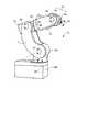
次に、図1および図2に示した一体型筐体100を適用するロボットの例について図3を用いて説明する。図3は、ロボット10の斜視図である。ここで、ロボット10は、たとえば、総重量が10kg未満の小型ロボットである。なお、一体型筐体100をロボット10よりも大型のロボットに適用することとしてもよい。 Next, an example of a robot to which the
図3に示すように、ロボット10は、旋回軸A0〜第5軸A5の6軸を有するいわゆる垂直多関節ロボットである。このように、ロボット10は、6軸のロボットであるので、先端の位置について3つの自由度を有し、先端の向きについて3つの自由度を有する。つまり、先端を3次元の任意の位置、かつ、3次元の任意の向きに自由に変更することができる。 As shown in FIG. 3, the
図3に示したように、ロボット10は、基端側から先端側へ向けて、ベース部10Bと、旋回部10Sと、第1アーム11と、第2アーム12と、第3アーム13と、手首部14とを備える。また、手首部14の先端側には、ワークを保持する任意のツールを着脱可能に取り付けることができる。 As shown in FIG. 3, the
なお、「アーム」の概念には、第1アーム11、第2アーム12および第3アーム13に加えて手首部14や旋回部10Sも含まれるものとする。つまり、ロボット10において回転や旋回などの可動部位を「アーム」と呼ぶことができる。 The concept of "arm" includes the
ベース部10Bは、たとえば、箱状の形状を有しており、作業机などの設置面に載置することができる。旋回部10Sは、ベース部10Bに支持され、設置面と垂直な旋回軸A0まわりに旋回する。第1アーム11は、基端側が旋回部10Sに支持され、旋回軸A0と垂直な第1軸A1まわりに旋回する。第2アーム12は、基端側が第1アーム11の先端側に支持され、第1軸A1と平行な第2軸A2まわりに旋回する。 The
第3アーム13は、基端側が第2アーム12の先端側に支持され、第2軸A2と垂直な第3軸A3まわりに回転する。手首部14は、旋回部14aと、回転部14bとを含む。旋回部14aは、基端側が第3アーム13の先端側に支持され、第3軸A3と垂直な第4軸A4まわりに旋回する。 The base end side of the
回転部14bは、基端側が旋回部14aの先端側に支持され、第4軸A4と直交する第5軸A5まわりに回転する。また、回転部14bの先端側には、上記したツール等を取り付けることができる。なお、旋回部14aおよび回転部14bは中空であり、ツールに接続するケーブルやチューブ等がかかる中空部分に挿通される。これにより、手首部14まわりにケーブル等を配索する必要がないので、ロボット10の作業性を向上させることができる。 The base end side of the
なお、以下では、図3に示したロボット10の第3アーム13に、図1に示した一体型筐体100を適用した場合について説明する。なお、ロボット10における他の構成要素に一体型筐体100を適用することとしてもよい。たとえば、ベース部10B、旋回部10S、第1アーム11、第2アーム12、第3アーム13、手首部14の旋回部14aあるいは回転部14bの少なくとも1つ以上に一体型筐体100を適用することができる。 In the following, a case where the
なお、一般的に、ロボット10は、先端側の構成要素のほうが、基端側の構成要素よりも重力や慣性力による応力を受けにくいので、先端側の構成要素の剛性は基端側の構成要素の剛性より低くても構わない。したがって、先端側の構成要素のほうが基端側の構成要素よりも一体型筐体100による軽量化の効果を効果的に得ることができる。 In general, the
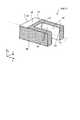
次に、図1に示した一体型筐体100を、図3に示したロボット10の第3アーム13に適用した場合について図4を用いて説明する。図4は、一体型筐体100を適用した第3アーム13の斜視図である。なお、図4では、一体型筐体100の内部に収容される駆動系等の各種装置を省略している。つまり、図4に示した第3アーム13は、一体型筐体100そのものであり金属等の材料で一体成形される。 Next, a case where the
なお、図4に示した一体型筐体100は、第3アーム13の外形に適用した形状としているため、図1に示した場合よりも複雑な形状を有している。なお、形状が複雑となっても、一体型筐体100の外壁に、外皮部110や骨組み部120を含む点では、図1の場合と同様である。つまり、第3アーム13に一体型筐体100を適用することで、第3アーム13の剛性を確保しつつ、第3アーム13の軽量化を図ることができる。 Since the
まず、第3アーム13の外形について説明する。第3アーム13は、内部が空洞である箱状の基端部101と、基端部101における先端側(X軸正方向側)の端面から延伸する一対の延伸部102とを備える。各延伸部102も内部が空洞であり、かかる空洞は基端部101の空洞と連通している。また、基端部101の基端側(X軸負方向側)の端面には第2アーム12(図3参照)へ取り付けるための取付部103が設けられている。これにより、第3アーム13は、第2アーム12における可動部の回転に伴って中心線CLまわりに回転する。 First, the outer shape of the
図4に示すように、第3アーム13における側面(Y軸正方向側および負方向側)は、平面状の縁部105を残して開放されている。つまり、縁部105は、開放された空間を取り囲んでおり、縁部105の端面は1つの平面上(図4では、XZ平面と平行な平面上)にある。 As shown in FIG. 4, the side surfaces (Y-axis positive direction side and negative direction side) of the
これにより、縁部105は、後述するカバーCV(図6参照)との間で気密性を保持しやすい。なお、以下では、縁部105で囲む部位を開口部150と記載する。つまり、開口部150は、周囲が略平面な部位に設けられている。 As a result, the
また、基端部101の上面(Z軸正方向側)および下面(Z軸負方向側)は、外面側が外皮部110で内面側が骨組み部120となる外壁である。なお、図4では、基端部101の内部に骨組み部120が設けられているが、このように、第3アーム13の剛性を高めるリブに相当する形状を適宜設けることとしてもよい。 Further, the upper surface (Z-axis positive direction side) and the lower surface (Z-axis negative direction side) of the
また、基端部101の上面には突出部210が設けられる。突出部210には、たとえば、手首部14における回転部14bに取り付けられるツールに配索されるチューブ等の接続口が設けられる。このように、外皮部110の外側に突出する形状を適宜設けることとしてもよい。 Further, a protruding
また、図4に示したように、基端部101および延伸部102の内部には支持部200が設けられているが、このように、内部に収容される駆動系等の各種装置を取り付けるための形状を適宜設けることとしてもよい。 Further, as shown in FIG. 4, a
また、基端部101の上面および下面の先端側(X軸正方向側)および一対の延伸部102の上面から下面に連続する面には、骨組み部120が外部に露出する部位が設けられる。以下では、かかる部位についても開口部150と記載する場合もある。また、一対の延伸部102における内側面(中心線CL側の側面)には、たとえば、円形状の空隙部160が設けられる。このように、外壁の一部から外皮部110および骨組み部120の双方を省略した空隙部160を設けることとしてもよい。 Further, a portion where the
このように、第3アーム13(一体型筐体100)では、外面が外皮部110で内面が骨組み部120の外壁と、外面の外皮部110を省略して骨組み部120が外部に露出する外壁(開口部150)と、外皮部110および骨組み部120を双方とも省略することで形成される空隙部160とを混在させることができる。 As described above, in the third arm 13 (integrated housing 100), the outer surface is the
なお、開口部150は、後述するカバーCV(図6参照)で密閉することができる。また、空隙部160は、駆動系等の各種装置を取り付けることで密閉することができる。なお、以下では、開口部150と空隙部160とをまとめて開口部150と記載することがある。 The
次に、外皮部110等の省略パターンについて図5を用いて説明する。図5は、第3アーム13の模式図である。ここで、図5は、図4に示した第3アーム13の外形を模式化した図である。 Next, the omitted pattern of the
図5に示すように、面SFは、外面が外皮部110で内面が骨組み部120の外壁に対応する。面SNは、外皮部110および骨組み部120の双方を省略した部位に対応する。面SHは、外皮部110を省略して骨組み部120を外部に露出させた外壁に対応する。なお、外皮部110を省略しても剛性にはほぼ影響がない。 As shown in FIG. 5, the surface SF corresponds to the outer wall of the
なお、図5に示した模式図は、中心線CLを含むXY平面について対向する面が同種類(面SF、面SHおよび面SNのいずれか)であり、中心線CLを含むXZ平面について対向する面も同種類(面SF、面SHおよび面SNのいずれか)であるものとする。 In the schematic diagram shown in FIG. 5, the planes facing the XY plane including the center line CL are of the same type (any of the plane SF, the plane SH, and the plane SN), and the planes facing the XZ plane including the center line CL are opposed to each other. It is assumed that the surfaces to be used are of the same type (any of surface SF, surface SH, and surface SN).
このように、一体型筐体100では、第3アーム13における各部の機能に応じて面SF、面SHおよび面SNを混在させることができる。また、上記したように、内部と連通する面SHおよび面SNについては、適宜、密封することで第3アーム13自体の気密性を確保することができる。 As described above, in the
次に、図5に示した面SHおよび面SNを密封するカバーCVについて図6を用いて説明する。図6は、カバーCVを示す分解斜視図である。なお、図6では、Y軸負方向側と、正方向側とで2つのカバーCVが存在するので、2つを区別する場合には、Y軸負方向側をカバーCV1と、正方向側をカバーCV2と記載することとする。 Next, the cover CV for sealing the surface SH and the surface SN shown in FIG. 5 will be described with reference to FIG. FIG. 6 is an exploded perspective view showing the cover CV. In FIG. 6, there are two cover CVs on the Y-axis negative direction side and the positive direction side. Therefore, when distinguishing between the two, the Y-axis negative direction side is the cover CV1 and the positive direction side is the cover CV1. It will be described as cover CV2.
図6に示すように、カバーCVは、開口部150(図4参照)を少なくとも覆い、一体型筐体100に対して着脱可能である。このように、カバーCVを着脱可能とすることで、ロボット10(図3参照)の組み立て性やメンテナンス性を高めることができる。また、ロボット10の気密性を確保することができる。これにより、ロボット10内部からの異物の流出や、ロボット外部からの異物の流入を防止することができる。 As shown in FIG. 6, the cover CV covers at least the opening 150 (see FIG. 4) and is removable from the
また、カバーCVは、開口部150を囲む蓋部Lを備える。なお、蓋部Lは、図4に示した縁部105に密着することで気密性を確保する。なお、縁部105またはカバーCVにおける対応する位置に、Oリングを設けるなどしてさらに気密性を高めることとしてもよい。 Further, the cover CV includes a lid portion L surrounding the
また、カバーCVは、弾性変形する樹脂等の素材で形成される。これにより、一体型筐体100への取り付けにボルト等の締結部材が不要となるので、部品点数を削減することができ、さらには、第3アーム13の軽量化を図ることができる。なお、カバーCVを塑性変形する樹脂等の素材で形成することとし、一旦取り付けた後に取り外す必要が生じた場合には使い捨てとすることとしてもよい。 Further, the cover CV is formed of a material such as a resin that elastically deforms. As a result, a fastening member such as a bolt is not required for attachment to the
また、カバーCVは、開口部150を外部から覆いつつ第3アーム13に係止される係止部C1と、第3アーム13の内部に突出しつつ第3アーム13に係止される係止部C2とを備える。ここで、係止部C1および係止部C2は、上記したように弾性変形するので、着脱が容易である。 Further, the cover CV has a locking portion C1 that is locked to the
なお、カバーCV全体としては弾性変形せず、係止部C1および係止部C2が弾性変形するようにしてもよい。たとえば、蓋部Lについては、係止部C1および係止部C2よりも厚みを厚くすることで変形を防止しつつ、係止部C1および係止部C2については変形する程度の厚みとすることで弾性変形させることとしてもよい。 The cover CV as a whole may not be elastically deformed, and the locking portion C1 and the locking portion C2 may be elastically deformed. For example, the lid portion L is thicker than the locking portion C1 and the locking portion C2 to prevent deformation, while the locking portion C1 and the locking portion C2 are thick enough to be deformed. It may be elastically deformed with.
なお、図6に示したカバーCV1における係止部C1と、カバーCV2における係止部C1とが互いに係止されるように、各係止部C1の先端側にお互いに噛み合う凸部や凹部を設けることとしてもよい。また、図6のカバーCV1,CV2に示したように、縁部C5は、図4に示した縁部105に対応する形状を有しており、縁部105に密着することで気密性を確保する。 A convex portion or a concave portion that meshes with each other is provided on the tip end side of each locking portion C1 so that the locking portion C1 of the cover CV1 and the locking portion C1 of the cover CV2 shown in FIG. 6 are locked to each other. It may be provided. Further, as shown in the covers CV1 and CV2 of FIG. 6, the edge portion C5 has a shape corresponding to the
また、図6のカバーCV1,CV2に示したように、袴部C6は、図4に示した延伸部102における開口部150に沿った形状を有しており、開口部150に密着することで気密性を確保する。なお、カバーCV1で覆われる一体型筐体100の部位には、たとえば、手首部14(図3参照)の旋回部14aに駆動力を伝達するプーリやベルトが収納される。また、カバーCV2で覆われる一体型筐体100の部位には、たとえば、手首部14(図3参照)の回転部14bに駆動力を伝達するプーリやベルトが収納される。 Further, as shown in the covers CV1 and CV2 of FIG. 6, the hakama portion C6 has a shape along the
なお、図6では、2つのカバーCV1,CV2を例示したが、カバーCVの個数については、第3アーム13の形状にあわせて任意の個数とすることができる。たとえば、延伸部102(図4参照)が1つのいわゆる片持ち形状である場合には、カバーCVを1つとすることができる。 Although two covers CV1 and CV2 are illustrated in FIG. 6, the number of cover CVs can be any number according to the shape of the
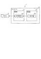
次に、ロボットシステム1の構成について図7を用いて説明する。図7は、ロボットシステム1の構成を示すブロック図である。図7に示すように、ロボットシステム1は、ロボット10と、コントローラ20とを備える。なお、ロボット10の構成については図3を用いて既に説明したので、ここでの説明を省略する。 Next, the configuration of the
図3に示すように、コントローラ20には、ロボット10が接続されている。また、コントローラ20は、制御部21と、記憶部22とを備える。制御部21は、動作制御部21aを備える。記憶部22は、教示情報22aを記憶する。 As shown in FIG. 3, a
ここで、コントローラ20は、たとえば、CPU(Central Processing Unit)、ROM(Read Only Memory)、RAM(Random Access Memory)、HDD(Hard Disk Drive)、入出力ポートなどを有するコンピュータや各種の回路を含む。 Here, the controller 20 includes, for example, a computer having a CPU (Central Processing Unit), a ROM (Read Only Memory), a RAM (Random Access Memory), an HDD (Hard Disk Drive), an input / output port, and various circuits. ..
コンピュータのCPUは、たとえば、ROMに記憶されたプログラムを読み出して実行することによって、制御部21の動作制御部21aとして機能する。また、動作制御部21aの少なくとも一部または全部をASIC(Application Specific Integrated Circuit)やFPGA(Field Programmable Gate Array)等のハードウェアで構成することもできる。 The CPU of the computer functions as the
また、記憶部22は、たとえば、RAMやHDDに対応する。RAMやHDDは、教示情報22aを記憶することができる。なお、コントローラ20は、有線や無線のネットワークで接続された他のコンピュータや可搬型記録媒体を介して上記したプログラムや各種情報を取得することとしてもよい。 Further, the
制御部21は、ロボット10の動作制御を行う。動作制御部21aは、教示情報22aに基づいてロボット10を動作させる。ここで、教示情報22aは、ロボット10に対するティーチング段階で作成され、ロボット10の動作経路を規定するプログラムである「ジョブ」を含んだ情報である。なお、動作制御部21aは、ロボット10に内蔵されるアクチュエータからのフィードバック値等に基づいて動作精度を向上させる処理を併せて行う。 The control unit 21 controls the operation of the
次に、一体型筐体100(図1参照)における断面形状の変形例について図8を用いて説明する。図8は、一体型筐体100の変形例を示す断面図である。なお、図8は、図2に対応する方向視の断面図に相当する。 Next, a modified example of the cross-sectional shape of the integrated housing 100 (see FIG. 1) will be described with reference to FIG. FIG. 8 is a cross-sectional view showing a modified example of the
図8に示すように、変形例に係る一体型筐体100Aは、空隙を囲む基本形状P2を外皮部110の面の「法線向き」に繰り返す骨組み形状の骨組み部120Aを、対向する2つの外皮部110の間に有する点で、図1に示した一体型筐体100とは異なる。 As shown in FIG. 8, in the
なお、図8では、基本形状P2として三角形状を例示したが、四角形状や六角形状であってもよい。また、一体型筐体100Aも金属3Dプリンタで形成することができるので、一体型筐体100Aの外形や内形を様々な形状とすることが可能である。 In FIG. 8, a triangular shape is illustrated as the basic shape P2, but it may be a quadrangular shape or a hexagonal shape. Further, since the
図8に示したように、一対の外皮部110の間に骨組み部120Aを設けることとしても、一体型筐体100Aの剛性を確保しつつ軽量化を図ることができる。また、一体型筐体100Aは、内面側も外面側も外皮部110であるので、骨組み部120Aが露出しない。したがって、一体型筐体100Aの内面にも骨組み部120Aによる凹凸が生じないので、一体型筐体100Aにおける内部空間を効率よく利用することができる。 As shown in FIG. 8, even if the
なお、図8では、説明をわかりやすくする観点から、基本形状P2をX軸に沿って繰り返す場合を示したが、繰り返しの向きについては、XZ平面に沿う任意の向きとすることができる。また、繰り返しの途中で繰り返しの向きを変更することとしてもよいし、基本形状P2の形や大きさを変更することとしてもよい。 In FIG. 8, from the viewpoint of making the explanation easy to understand, the case where the basic shape P2 is repeated along the X axis is shown, but the direction of the repetition can be any direction along the XZ plane. Further, the direction of the repetition may be changed in the middle of the repetition, or the shape and size of the basic shape P2 may be changed.
上述してきたように、本実施形態に係るロボット10は、一体成形される一体型筐体100を有する少なくとも1つのアームを備える。一体型筐体100は、外皮部110と、骨組み部120とを備える。骨組み部120は、空隙を囲む基本形状P1を外皮部110の面に沿う向きに繰り返す骨組み形状を外皮部110の内面に有し、外皮部110よりも肉厚である。かかる一体型筐体100を用いることで、ロボット10の剛性を確保しつつロボット10の軽量化を図ることができる。 As described above, the
なお、上記した実施形態では、6軸のロボットを例示したが、ロボットの軸数は1軸以上の任意の個数とすることができる。また、上記した実施形態では、一体型筐体をロボットに適用する場合について説明したが、一体型筐体を自動車や列車などの移動体に適用することとしてもよい。また、一体型筐体を電子機器等の筐体に用いることとしてもよい。 In the above-described embodiment, a 6-axis robot is illustrated, but the number of axes of the robot can be any number of 1 or more axes. Further, in the above-described embodiment, the case where the integrated housing is applied to the robot has been described, but the integrated housing may be applied to a moving body such as an automobile or a train. Further, the integrated housing may be used for a housing of an electronic device or the like.
さらなる効果や変形例は、当業者によって容易に導き出すことができる。このため、本発明のより広範な態様は、以上のように表しかつ記述した特定の詳細および代表的な実施形態に限定されるものではない。したがって、添付の請求の範囲およびその均等物によって定義される総括的な発明の概念の精神または範囲から逸脱することなく、様々な変更が可能である。 Further effects and variations can be easily derived by those skilled in the art. For this reason, the broader aspects of the invention are not limited to the particular details and representative embodiments expressed and described as described above. Thus, various modifications can be made without departing from the spirit or scope of the general concept of the invention as defined by the appended claims and their equivalents.
1 ロボットシステム
10 ロボット
10B ベース部
10S 旋回部
11 第1アーム
12 第2アーム
13 第3アーム
14 手首部
14a 旋回部
14b 回転部
20 コントローラ
21 制御部
21a 動作制御部
22 記憶部
22a 教示情報
100 一体型筐体
101 基端部
102 延伸部
103 取付部
110 外皮部
120 骨組み部
150 開口部
160 空隙部
200 支持部
210 突出部
A0 旋回軸
A1 第1軸
A2 第2軸
A3 第3軸
A4 第4軸
A5 第5軸
CV カバー
C1,C2 係止部
L 蓋部
P1,P2 基本形状1
Claims (7)
Translated fromJapaneseを備え、
前記一体型筐体は、
外皮部と、
空隙を囲む基本形状を前記外皮部の面に沿う向きに繰り返す骨組み形状を前記外皮部の内面に有し、前記外皮部よりも肉厚な骨組み部と
を備えること
を特徴とするロボット。With at least one arm having an integral housing that is integrally molded,
The integrated housing is
Exodermis and
A robot characterized by having a skeleton shape that repeats a basic shape surrounding a gap in a direction along the surface of the exodermis on the inner surface of the exodermis, and having a skeleton that is thicker than the exodermis.
前記外皮部が省略される開口部を少なくとも一部に備えること
を特徴とする請求項1に記載のロボット。The integrated housing is
The robot according to claim 1, wherein the robot is provided with at least a part of an opening from which the exodermis portion is omitted.
周囲が略平面な部位に設けられ、
前記一体型筐体を有するアームは、
前記開口部を外側から覆う着脱可能なカバーを備えること
を特徴とする請求項2に記載のロボット。The opening is
The circumference is provided on a substantially flat part,
The arm having the integrated housing
The robot according to claim 2, further comprising a removable cover that covers the opening from the outside.
弾性変形すること
を特徴とする請求項3に記載のロボット。The cover is
The robot according to claim 3, wherein the robot is elastically deformed.
前記外皮部が略平面な部位に接して前記開口部を囲む蓋部と、
弾性変形することで前記一体型筐体に係止される係止部と
を備えること
を特徴とする請求項4に記載のロボット。The cover is
A lid portion in which the exodermis portion is in contact with a substantially flat portion and surrounds the opening portion,
The robot according to claim 4, further comprising a locking portion that is elastically deformed to be locked to the integrated housing.
前記骨組み形状としてトラス形状を含むこと
を特徴とする請求項1〜5のいずれか一つに記載のロボット。The skeleton
The robot according to any one of claims 1 to 5, wherein the skeleton shape includes a truss shape.
金属用3Dプリンタによって造形される金属製であること
を特徴とする請求項1〜6のいずれか一つに記載のロボット。The integrated housing is
The robot according to any one of claims 1 to 6, wherein the robot is made of metal formed by a 3D printer for metal.
Applications Claiming Priority (1)
| Application Number | Priority Date | Filing Date | Title |
|---|---|---|---|
| PCT/JP2018/029767WO2020031289A1 (en) | 2018-08-08 | 2018-08-08 | Robot |
Publications (2)
| Publication Number | Publication Date |
|---|---|
| JPWO2020031289A1true JPWO2020031289A1 (en) | 2021-06-03 |
| JP7028330B2 JP7028330B2 (en) | 2022-03-02 |
Family
ID=69413269
Family Applications (1)
| Application Number | Title | Priority Date | Filing Date |
|---|---|---|---|
| JP2020535391AActiveJP7028330B2 (en) | 2018-08-08 | 2018-08-08 | robot |
Country Status (3)
| Country | Link |
|---|---|
| JP (1) | JP7028330B2 (en) |
| CN (1) | CN112566760B (en) |
| WO (1) | WO2020031289A1 (en) |
Cited By (1)
| Publication number | Priority date | Publication date | Assignee | Title |
|---|---|---|---|---|
| US20240075639A1 (en)* | 2022-09-07 | 2024-03-07 | Kabushiki Kaisha Yaskawa Denki | Robot |
Families Citing this family (3)
| Publication number | Priority date | Publication date | Assignee | Title |
|---|---|---|---|---|
| JP6834045B1 (en) | 2020-04-02 | 2021-02-24 | 株式会社安川電機 | robot |
| JP7037210B2 (en)* | 2020-07-01 | 2022-03-16 | 有限会社タクショー | Cleaner |
| WO2023144943A1 (en)* | 2022-01-26 | 2023-08-03 | ヤマハ発動機株式会社 | Robot with joint |
Citations (12)
| Publication number | Priority date | Publication date | Assignee | Title |
|---|---|---|---|---|
| JPS61192490A (en)* | 1985-02-22 | 1986-08-27 | フアナツク株式会社 | Arm structure of robot for clean room |
| JPH05123984A (en)* | 1991-10-30 | 1993-05-21 | Smc Corp | Structural member used for actuator, robot, or the like |
| JPH07328983A (en)* | 1994-06-13 | 1995-12-19 | Fanuc Ltd | Cable processing device for industrial robot |
| JP2001162578A (en)* | 1999-12-13 | 2001-06-19 | Denso Corp | Robot |
| US20130160591A1 (en)* | 2011-12-23 | 2013-06-27 | Fabworx Solutions, Inc. | Extended Wrist Assembly for Robotic Arm |
| CN204248885U (en)* | 2014-11-10 | 2015-04-08 | 泉州市微柏工业机器人研究院有限公司 | A kind of swing arm of manipulator and manipulator |
| CN104858892A (en)* | 2015-06-11 | 2015-08-26 | 佛山市南海区广工大数控装备协同创新研究院 | Modularized robot based on intelligent mechanical arm |
| CN105057631A (en)* | 2015-08-11 | 2015-11-18 | 华南理工大学 | Aluminum alloy pressure casting mechanical arm with gradient net-shaped structure and manufacturing method of aluminum alloy pressure casting mechanical arm |
| CN206501120U (en)* | 2016-12-30 | 2017-09-19 | 华南智能机器人创新研究院 | One kind service humanoid robot |
| US20170368679A1 (en)* | 2016-06-27 | 2017-12-28 | Massachusetts Institute Of Technology | Bipedal Isotropic Lattice Locomoting Explorer: Robotic Platform for Locomotion and Manipulation of Discrete Lattice Structures and Lightweight Space Structures |
| CN207373207U (en)* | 2017-10-20 | 2018-05-18 | 广东伯朗特智能装备股份有限公司 | A kind of new machine human arm |
| JP2018100445A (en)* | 2016-12-16 | 2018-06-28 | キヤノン株式会社 | Method of manufacturing article |
Family Cites Families (10)
| Publication number | Priority date | Publication date | Assignee | Title |
|---|---|---|---|---|
| CN2561847Y (en)* | 2002-04-30 | 2003-07-23 | 邱则有 | Durable formwork for building ceiling cast in situs |
| JP4801471B2 (en)* | 2006-03-06 | 2011-10-26 | 株式会社住軽日軽エンジニアリング | Single layer lattice dome structure |
| CN102009697A (en)* | 2010-06-13 | 2011-04-13 | 贾秉成 | Connection structure of vehicle frame |
| CN201694260U (en)* | 2010-06-13 | 2011-01-05 | 贾秉成 | Vehicle frame connection structure |
| CN203558123U (en)* | 2013-09-23 | 2014-04-23 | 北京汉能创昱科技有限公司 | Lightweight steering knuckle |
| CN103770929A (en)* | 2014-02-11 | 2014-05-07 | 中航飞机股份有限公司西安飞机分公司 | Integral aircraft panel structure with reinforcing grid ribs |
| CN204935673U (en)* | 2015-08-11 | 2016-01-06 | 华南理工大学 | A kind of bionical groove structure punching press aluminium alloy mechanical arm |
| CN105966488A (en)* | 2016-06-02 | 2016-09-28 | 北京航空航天大学 | Six-wheel-leg movable operation robot test platform |
| CN206711940U (en)* | 2017-04-25 | 2017-12-05 | 河南鹏翔模塑有限公司 | High-strength light-weight battery case lower box |
| CN207267446U (en)* | 2017-08-29 | 2018-04-24 | 石嘴山市鼎力支护设备有限公司 | Lightweight hatch door for new-energy automobile |
- 2018
- 2018-08-08JPJP2020535391Apatent/JP7028330B2/enactiveActive
- 2018-08-08WOPCT/JP2018/029767patent/WO2020031289A1/ennot_activeCeased
- 2018-08-08CNCN201880096393.7Apatent/CN112566760B/enactiveActive
Patent Citations (12)
| Publication number | Priority date | Publication date | Assignee | Title |
|---|---|---|---|---|
| JPS61192490A (en)* | 1985-02-22 | 1986-08-27 | フアナツク株式会社 | Arm structure of robot for clean room |
| JPH05123984A (en)* | 1991-10-30 | 1993-05-21 | Smc Corp | Structural member used for actuator, robot, or the like |
| JPH07328983A (en)* | 1994-06-13 | 1995-12-19 | Fanuc Ltd | Cable processing device for industrial robot |
| JP2001162578A (en)* | 1999-12-13 | 2001-06-19 | Denso Corp | Robot |
| US20130160591A1 (en)* | 2011-12-23 | 2013-06-27 | Fabworx Solutions, Inc. | Extended Wrist Assembly for Robotic Arm |
| CN204248885U (en)* | 2014-11-10 | 2015-04-08 | 泉州市微柏工业机器人研究院有限公司 | A kind of swing arm of manipulator and manipulator |
| CN104858892A (en)* | 2015-06-11 | 2015-08-26 | 佛山市南海区广工大数控装备协同创新研究院 | Modularized robot based on intelligent mechanical arm |
| CN105057631A (en)* | 2015-08-11 | 2015-11-18 | 华南理工大学 | Aluminum alloy pressure casting mechanical arm with gradient net-shaped structure and manufacturing method of aluminum alloy pressure casting mechanical arm |
| US20170368679A1 (en)* | 2016-06-27 | 2017-12-28 | Massachusetts Institute Of Technology | Bipedal Isotropic Lattice Locomoting Explorer: Robotic Platform for Locomotion and Manipulation of Discrete Lattice Structures and Lightweight Space Structures |
| JP2018100445A (en)* | 2016-12-16 | 2018-06-28 | キヤノン株式会社 | Method of manufacturing article |
| CN206501120U (en)* | 2016-12-30 | 2017-09-19 | 华南智能机器人创新研究院 | One kind service humanoid robot |
| CN207373207U (en)* | 2017-10-20 | 2018-05-18 | 广东伯朗特智能装备股份有限公司 | A kind of new machine human arm |
Cited By (1)
| Publication number | Priority date | Publication date | Assignee | Title |
|---|---|---|---|---|
| US20240075639A1 (en)* | 2022-09-07 | 2024-03-07 | Kabushiki Kaisha Yaskawa Denki | Robot |
Also Published As
| Publication number | Publication date |
|---|---|
| CN112566760B (en) | 2024-08-20 |
| JP7028330B2 (en) | 2022-03-02 |
| CN112566760A (en) | 2021-03-26 |
| WO2020031289A1 (en) | 2020-02-13 |
Similar Documents
| Publication | Publication Date | Title |
|---|---|---|
| JP7028330B2 (en) | robot | |
| Taghirad | Parallel robots: mechanics and control | |
| ES2644939T3 (en) | Method and system to determine at least one property of a manipulator | |
| ES3000746T3 (en) | Method of suppressing vibrations of a robot arm with external objects | |
| Chi et al. | Multi-objective optimization of stiffness and workspace for a parallel kinematic machine | |
| CN103659814A (en) | Robot, robot control device, and robot system | |
| JP2019084607A (en) | Robot and robot system | |
| JP2018183843A (en) | robot | |
| JP2019063938A (en) | Robot and robot system | |
| JP2019063940A (en) | robot | |
| Chi et al. | Stiffness optimization of a novel reconfigurable parallel kinematic manipulator | |
| Zhu et al. | Kinematic and dynamic modelling for real-time control of Tau parallel robot | |
| Choudhury et al. | Planar parallel manipulators: A review on kinematic, dynamic, and control aspects | |
| Palmieri et al. | Mechanical design of a mini pointing device for a robotic assembly cell | |
| Li et al. | Compliant mechanism reconfiguration based on position space concept for reducing parasitic motion | |
| JP6863397B2 (en) | robot | |
| Kunt | Microfactory concept with bilevel modularity | |
| JP2018001313A (en) | Robot, robot control device, and robot system | |
| US20210046640A1 (en) | Drive device and robot device | |
| Dash | An Application of a 3-RRRS 6 DOF Parallel Manipulator | |
| JP2005342842A (en) | Driving force transmission mechanism and micromanipulator | |
| Yang et al. | A General Kinematic Modeling Framework for a 3D Compliant Micromechanism | |
| JP4873946B2 (en) | Assembly equipment | |
| JPH0425385A (en) | Articulated robot | |
| Ronchi et al. | High resolution flexible 3-RRR planar parallel micro-stage in near singular configuration for resolution improvement. Part I |
Legal Events
| Date | Code | Title | Description |
|---|---|---|---|
| A621 | Written request for application examination | Free format text:JAPANESE INTERMEDIATE CODE: A621 Effective date:20201119 | |
| A131 | Notification of reasons for refusal | Free format text:JAPANESE INTERMEDIATE CODE: A131 Effective date:20210803 | |
| A521 | Request for written amendment filed | Free format text:JAPANESE INTERMEDIATE CODE: A523 Effective date:20210819 | |
| TRDD | Decision of grant or rejection written | ||
| A01 | Written decision to grant a patent or to grant a registration (utility model) | Free format text:JAPANESE INTERMEDIATE CODE: A01 Effective date:20220118 | |
| A61 | First payment of annual fees (during grant procedure) | Free format text:JAPANESE INTERMEDIATE CODE: A61 Effective date:20220131 | |
| R150 | Certificate of patent or registration of utility model | Ref document number:7028330 Country of ref document:JP Free format text:JAPANESE INTERMEDIATE CODE: R150 | |
| R250 | Receipt of annual fees | Free format text:JAPANESE INTERMEDIATE CODE: R250 |