JPWO2019138515A1 - Image creator, spectacle lens selection system, image creation method and program - Google Patents
Image creator, spectacle lens selection system, image creation method and programDownload PDFInfo
- Publication number
- JPWO2019138515A1 JPWO2019138515A1JP2019564219AJP2019564219AJPWO2019138515A1JP WO2019138515 A1JPWO2019138515 A1JP WO2019138515A1JP 2019564219 AJP2019564219 AJP 2019564219AJP 2019564219 AJP2019564219 AJP 2019564219AJP WO2019138515 A1JPWO2019138515 A1JP WO2019138515A1
- Authority
- JP
- Japan
- Prior art keywords
- image
- subject
- spectacle lens
- display device
- unit
- Prior art date
- Legal status (The legal status is an assumption and is not a legal conclusion. Google has not performed a legal analysis and makes no representation as to the accuracy of the status listed.)
- Granted
Links
Images


Classifications
- A—HUMAN NECESSITIES
- A61—MEDICAL OR VETERINARY SCIENCE; HYGIENE
- A61B—DIAGNOSIS; SURGERY; IDENTIFICATION
- A61B3/00—Apparatus for testing the eyes; Instruments for examining the eyes
- A61B3/0016—Operational features thereof
- A61B3/0025—Operational features thereof characterised by electronic signal processing, e.g. eye models
- A—HUMAN NECESSITIES
- A61—MEDICAL OR VETERINARY SCIENCE; HYGIENE
- A61B—DIAGNOSIS; SURGERY; IDENTIFICATION
- A61B3/00—Apparatus for testing the eyes; Instruments for examining the eyes
- A61B3/0016—Operational features thereof
- A61B3/0041—Operational features thereof characterised by display arrangements
- A—HUMAN NECESSITIES
- A61—MEDICAL OR VETERINARY SCIENCE; HYGIENE
- A61B—DIAGNOSIS; SURGERY; IDENTIFICATION
- A61B3/00—Apparatus for testing the eyes; Instruments for examining the eyes
- A61B3/02—Subjective types, i.e. testing apparatus requiring the active assistance of the patient
- A61B3/028—Subjective types, i.e. testing apparatus requiring the active assistance of the patient for testing visual acuity; for determination of refraction, e.g. phoropters
- A61B3/032—Devices for presenting test symbols or characters, e.g. test chart projectors
- A—HUMAN NECESSITIES
- A61—MEDICAL OR VETERINARY SCIENCE; HYGIENE
- A61B—DIAGNOSIS; SURGERY; IDENTIFICATION
- A61B3/00—Apparatus for testing the eyes; Instruments for examining the eyes
- A61B3/02—Subjective types, i.e. testing apparatus requiring the active assistance of the patient
- A61B3/028—Subjective types, i.e. testing apparatus requiring the active assistance of the patient for testing visual acuity; for determination of refraction, e.g. phoropters
- A61B3/04—Trial frames; Sets of lenses for use therewith
- A—HUMAN NECESSITIES
- A61—MEDICAL OR VETERINARY SCIENCE; HYGIENE
- A61B—DIAGNOSIS; SURGERY; IDENTIFICATION
- A61B3/00—Apparatus for testing the eyes; Instruments for examining the eyes
- A61B3/10—Objective types, i.e. instruments for examining the eyes independent of the patients' perceptions or reactions
- A61B3/113—Objective types, i.e. instruments for examining the eyes independent of the patients' perceptions or reactions for determining or recording eye movement
- G—PHYSICS
- G06—COMPUTING OR CALCULATING; COUNTING
- G06F—ELECTRIC DIGITAL DATA PROCESSING
- G06F3/00—Input arrangements for transferring data to be processed into a form capable of being handled by the computer; Output arrangements for transferring data from processing unit to output unit, e.g. interface arrangements
- G06F3/14—Digital output to display device ; Cooperation and interconnection of the display device with other functional units
- G06F3/147—Digital output to display device ; Cooperation and interconnection of the display device with other functional units using display panels
Landscapes
- Health & Medical Sciences (AREA)
- Life Sciences & Earth Sciences (AREA)
- Engineering & Computer Science (AREA)
- Physics & Mathematics (AREA)
- Medical Informatics (AREA)
- Animal Behavior & Ethology (AREA)
- Veterinary Medicine (AREA)
- Public Health (AREA)
- Biophysics (AREA)
- Ophthalmology & Optometry (AREA)
- Biomedical Technology (AREA)
- Heart & Thoracic Surgery (AREA)
- General Health & Medical Sciences (AREA)
- Molecular Biology (AREA)
- Surgery (AREA)
- Theoretical Computer Science (AREA)
- Human Computer Interaction (AREA)
- General Engineering & Computer Science (AREA)
- General Physics & Mathematics (AREA)
- Signal Processing (AREA)
- Processing Or Creating Images (AREA)
- Eyeglasses (AREA)
- Eye Examination Apparatus (AREA)
- Image Analysis (AREA)
- Controls And Circuits For Display Device (AREA)
- Image Processing (AREA)
Abstract
Translated fromJapaneseDescription
Translated fromJapanese本発明は、画像作成装置、眼鏡レンズ選択システム、画像作成方法およびプログラムに関する。 The present invention relates to an image creation device, a spectacle lens selection system, an image creation method and a program.
眼鏡レンズの装用者が、仮想的な眼鏡レンズを通して目視した場合の視野の画像を生成するため、種々の方法の提案がなされている。例えば、特許文献1では、頭部に装着可能で、距離画像センサにより取得した情報を利用する装置が記載されている。このような装置よりも簡易的な構成で、被験者に眼鏡レンズを通した見え方をリアルに体験させることが望まれている。 Various methods have been proposed for the wearer of the spectacle lens to generate an image of the visual field when viewed through a virtual spectacle lens. For example,
本発明の第1の態様によると、画像作成装置は、表示装置を目視する被験者を撮像した撮像画像から、特徴を検出する特徴検出部と、検出された前記特徴の位置および/または検出された前記特徴の間の距離に基づいて、前記被験者と前記表示装置との間の距離および前記被験者の顔の向きを算出するパラメータ算出部と、前記被験者と前記表示装置との間の距離および前記顔の向きに基づいて、前記被験者が眼鏡レンズを通して前記表示装置を目視した場合の仮想的な視野の画像を作成する画像作成部と、前記仮想的な視野の画像を前記表示装置に表示させる表示制御部とを備える。
本発明の第2の態様によると、眼鏡レンズ選択システムは、第1の態様の画像作成装置と、前記表示装置と、前記表示装置を目視する被験者を撮像する撮像部とを備える。
本発明の第3の態様によると、画像作成方法は、表示装置を目視する被験者を撮像した撮像画像から、特徴を検出することと、検出された前記特徴の位置および/または検出された前記特徴の間の距離に基づいて、前記被験者と前記表示装置との間の距離および前記被験者の顔の向きを算出することと、前記被験者と前記表示装置との間の距離および前記顔の向きに基づいて、前記被験者が眼鏡レンズを通して前記表示装置を目視した場合の仮想的な視野の画像を作成することと、前記仮想的な視野の画像を前記表示装置に表示させることとを備える。
本発明の第4の態様によると、プログラムは、表示装置を目視する被験者を撮像した撮像画像から、特徴を検出する特徴検出処理と、検出された前記特徴の位置および/または検出された前記特徴の間の距離に基づいて、前記被験者と前記表示装置との間の距離および前記被験者の顔の向きを算出するパラメータ算出処理と、前記被験者と前記表示装置との間の距離および前記顔の向きに基づいて、前記被験者が眼鏡レンズを通して前記表示装置を目視した場合の仮想的な視野の画像を作成する画像作成処理と、前記仮想的な視野の画像を前記表示装置に表示させる表示制御処理とを処理装置に行わせるためのものである。According to the first aspect of the present invention, the image creation device has a feature detection unit that detects features and a position and / or detection of the detected features from an image captured by a subject who visually observes the display device. A parameter calculation unit that calculates the distance between the subject and the display device and the orientation of the subject's face based on the distance between the features, and the distance between the subject and the display device and the face. An image creation unit that creates an image of a virtual field of view when the subject visually observes the display device through a spectacle lens, and a display control that displays the image of the virtual field of view on the display device based on the orientation of the image. It has a part.
According to the second aspect of the present invention, the spectacle lens selection system includes an image creating device of the first aspect, the display device, and an imaging unit that images a subject who visually observes the display device.
According to a third aspect of the present invention, the image creation method detects a feature from an image captured by a subject who visually observes a display device, and the position of the detected feature and / or the detected feature. Based on the distance between the subject and the display device and the orientation of the subject's face, and based on the distance between the subject and the display device and the orientation of the face. The subject comprises creating an image of a virtual field of view when the subject visually observes the display device through a spectacle lens, and displaying the image of the virtual field of view on the display device.
According to a fourth aspect of the present invention, the program comprises a feature detection process for detecting a feature from an image of a subject viewing a display device, and a position of the detected feature and / or the detected feature. Parameter calculation processing for calculating the distance between the subject and the display device and the orientation of the subject's face based on the distance between the subject, and the distance between the subject and the display device and the orientation of the face. Based on the above, an image creation process for creating an image of a virtual field of view when the subject visually observes the display device through a spectacle lens, and a display control process for displaying the image of the virtual field of view on the display device. Is for letting the processing device perform.
以下の実施形態では、適宜図面を参照しながら、画像作成装置等について説明する。以下の説明では、眼鏡レンズにおける「上方」、「下方」、「上部」、「下部」等と表記する場合は、当該眼鏡レンズが装用されたときに装用者から見たレンズ内の位置関係に基づくものとする。 In the following embodiment, the image creating apparatus and the like will be described with reference to the drawings as appropriate. In the following description, when the terms "upper", "lower", "upper", "lower", etc. of the spectacle lens are used, the positional relationship within the lens as seen by the wearer when the spectacle lens is worn is used. It shall be based on.
図1は、本実施形態の画像作成装置の概略構成を示す概念図である。画像作成装置1は、撮像部10と、表示部20と、情報処理部30とを備える。情報処理部30は、入力部31と、通信部32と、記憶部33と、制御部40とを備える。制御部40は、特徴検出部41と、パラメータ算出部42と、画像作成部43と、表示制御部44とを備える。 FIG. 1 is a conceptual diagram showing a schematic configuration of the image creating apparatus of the present embodiment. The
画像作成装置1は、被験者Sが眼鏡レンズの形状データ等に基づいた仮想的な眼鏡レンズを通して表示部20を目視した場合の仮想的な視野の画像(以下、視野画像と呼ぶ)を作成する。 The
撮像部10は、カメラ等の撮像装置を備え、被験者Sの頭部、特に顔を撮像する。撮像して得た画像から、後述するパラメータ算出部42による処理に必要な特徴を検出することができれば、撮像部10はいずれの位置に配置されてもよい。撮像部10へ入射した光(画像)は光電変換されて光強度を示す信号となった後、A/D変換されて制御部40に入力される(矢印A1)。 The
表示部20は、液晶モニタ等の表示装置を備え、画像作成部43が作成した視野画像を表示制御部44の制御により表示する(矢印A2)。 The
情報処理部30は、電子計算機等の情報処理装置を備え、視野画像の作成等に必要な情報処理を行う。
なお、情報処理部30は、スマートフォンやノートパソコン等のように撮像部10および/若しくは表示部20と一体的に構成されていてもよく、または、撮像部10および/若しくは表示部20から物理的に離れた位置に配置されてもよい。さらに、情報処理部30が行う処理の一部は、遠隔に配置された電子計算機やサーバ等により行われてもよく、情報処理部30に記憶されるデータの少なくとも一部は、遠隔に配置されたサーバ等に記憶されてもよい。The
The
入力部31は、マウス、キーボード、各種ボタンおよび/またはタッチパネル等の入力装置を含んで構成される。入力部31は、制御部40の行う処理に必要な情報等を、ユーザから受け付ける。 The
通信部32は、インターネット等のネットワークに無線や有線接続により通信可能な通信装置を含んで構成され、被験者Sの処方データや眼鏡レンズの形状データを受信したり、適宜必要なデータを送受信する。 The
記憶部33は、不揮発性の記憶媒体で構成され、被験者Sの処方データや眼鏡レンズの形状データ等の各種データ、制御部40が処理を実行するためのプログラム等を記憶する。 The
制御部40は、CPU等のプロセッサを含んで構成され、記憶部33に記憶されたプログラムを実行し、画像作成装置1の各動作の主体となる。制御部40は、撮像部10が撮像して得た画像に基づいて視野画像を作成し、表示部20に表示させる。 The
制御部40の特徴検出部41は、撮像部10が撮像した被験者Sの頭部の画像から、画像処理により特徴を検出する。以下の説明で「特徴」とは、特徴点、エッジ、コーナーならびにこれらを適宜含む2次元および3次元の要素等の、画像処理により他の部分と区別可能な画像中の点、線、または部分とする。 The
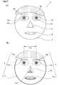
図2(A)は、撮像部10が被験者Sの頭部を撮像して得た画像(以下、被験者画像Isと呼ぶ)を模式的に示す図である。図2(A)の被験者画像Isは被験者Sを正面から撮像した画像となっており、被験者Sの顔における、左眉毛BL、右眉毛BR、左眼EL、右眼ER、左瞳孔PL、右瞳孔PR、鼻N、口唇M、顔の輪郭C等の、特徴的な構造または色彩等を有する部分が示されている。 FIG. 2A is a diagram schematically showing an image (hereinafter, referred to as subject image Is) obtained by imaging the head of subject S by the
図2(B)は、特徴検出部41が検出する特徴Fを示す図である。特徴検出部41は、被験者画像Isから、FAST法やキャニー法等の画像処理を用いて特徴点、エッジおよび/またはコーナー等の特徴Fの検出を行う。これらの特徴Fの少なくとも一部は、撮像部10に対する被験者Sの顔の向きが変化しても検出可能なものが好ましい。特徴検出部41は、記憶部33に記憶されている過去に取得された特徴Fの情報等に基づいて、検出した特徴Fが鼻N、顔の輪郭C等のいずれの顔の部分に対応するかを決定する。なお、特徴検出部41は、顔画像のデータセットを利用して機械学習することにより得られる顔特徴点検出モデルを、特徴Fとして検出してもよい。 FIG. 2B is a diagram showing a feature F detected by the
図2(B)には、被験者画像Isから特徴検出部41が検出する特徴Fとして、左眉毛BLに対応する線状の特徴FbL、右眉毛BRに対応する線状の特徴FbR、左眼ELの瞳孔中心に対応する特徴点FeL(以下、左眼特徴点と呼ぶ)、右眼ERの瞳孔中心に対応する特徴点FeR(以下、右眼特徴点と呼ぶ)、鼻尖に対応する特徴点Fna(以下、鼻特徴点と呼ぶ)、鼻Nに対応し、鼻根から鼻尖を通り左右の外鼻孔へと分岐した線分からなる特徴Fn、上下の口唇Mの赤い部分の輪郭に対応する特徴Fm、および顔の輪郭Cに対応する線状の特徴Fcが示されている。 In FIG. 2B, the feature F detected by the
特徴検出部41は,各特徴Fを構成する特徴点の座標のデータ、各特徴Fを構成する線分を表現する、複数の特徴点の座標を紐づけたデータ、および特徴Fと対応する顔の部分等を記憶部33に記憶させる。
なお、後述のパラメータ算出部42が所望のパラメータを算出することができれば、各特徴Fを表現するデータ構造は特に限定されない。The
The data structure expressing each feature F is not particularly limited as long as the
パラメータ算出部42は、特徴検出部41が検出した被験者画像Isにおける特徴Fの位置に基づいて、被験者Sの顔の位置および顔の向き等のパラメータを算出する。ここで、「顔の向き」は、図1にR、P、Yの記号でそれぞれ模式的に示された回転方向に対応する頭部のロール角、ピッチ角、ヨー角で記述することができる。ここで、ロール角は、被験者Sの前後方向に伸びる軸(z軸)の周りの回転角であり、ピッチ角は、被験者Sの左右方向に伸びる軸(x軸)の周りの回転角であり、ヨー角は、被験者Sの上下方向に伸びる軸(y軸)の周りの回転角である。図1には、x軸、y軸およびz軸の方向と向きを座標軸900で示した。
なお、座標系の取り方等、顔の向きの数学的な表現方法は特に限定されない。The
The mathematical expression method of the face orientation, such as how to take the coordinate system, is not particularly limited.
パラメータ算出部42が特徴Fから顔の向きを算出する方法は特に限定されない。例えばHorprasertらの論文(T. Horprasert, Y. Yacoob, and L. Davis, ”Computing 3-D Head Orientation from a Monocular Image Sequence,” Proceedings of the Second International Conference on Automatic Face and Gesture Recognition(米国), IEEE,1996年, pp.242-247)には眼の端(目頭、目尻)および鼻尖を含む数個の特徴点から頭部のロール角、ピッチ角、ヨー角を計算する方法が示されている。ここでは、目頭や目尻が同一直線上にあるとして計算を行っている。パラメータ算出部42による被験者Sの顔の向きの算出には、この論文で用いられているような、顔の一部に対応する特徴点が所定の空間的関係にあると仮定して計算する方法の他、様々な頭部姿勢推定(Head pose estimation)方法を用いて被験者画像Isから被験者Sの顔の向きを算出することができる。 The method by which the
パラメータ算出部42は、特徴検出部41が検出した被験者画像Isにおける特徴Fの位置と、パラメータ算出部42が算出した顔の向きと、被験者Sの顔の一部の長さの実測値とから、被験者Sの位置を算出することができる。パラメータ算出部42は、被験者画像Isにおける左眼特徴点FeLと右眼特徴点FeRとの間の距離PDiを、これらの特徴点の座標から算出する。パラメータ算出部42は、算出した画像上の距離PDiを、算出した顔の向きに基づいて顔の正面から見た場合の長さに変換し、この長さと実測した瞳孔間距離(PD)との比較に基づいて被験者Sと撮像部10との間の距離を算出する。 The
例えば、パラメータ算出部42は、撮像部10の撮像素子の焦点面の縦横のサイズと焦点距離とから、既知の瞳孔間距離PDが画像上の距離PDiとなる、撮像部10から被験者Sまでの距離を求めることができる。
なお、画像作成装置1が、ToF(Time of Flight)方式により測距を行って距離画像を撮像するToFカメラ、またはステレオカメラを備える等、被写体画像Isから検出した特徴Fを用いる以外の方法で撮像部10から被験者Sまでの距離を測定してもよい。For example, in the
It should be noted that the
図1に示されるように、パラメータ算出部42は、算出した被験者Sと撮像部10との間の距離Ezと、予め定められた撮像部10と表示部20との間の距離Czとの和により、被験者Sと表示部20との間の距離を算出する。また、パラメータ算出部42は、被験者Sと撮像部10との間の距離Ezと、撮像部10から見た被験者Sの眼Eの方向から、被験者Sの眼Eと撮像部10との間のy軸方向の距離Eyを算出する。パラメータ算出部42は、この距離Eyと、予め定められた表示部20の位置Oと撮像部10との間のy軸方向の距離Cyとから、表示部20を基準とした眼Eのy軸方向の位置を算出する。パラメータ算出部42は、x軸方向についてもy軸方向と同様に計算して、表示部20を基準とした眼Eの三次元位置を算出する。撮像部10と表示部20との位置関係を示す距離Cy,Cz等は、入力部31を介してユーザにより入力されるか、予め記憶部33に記憶された数値を用いる。
なお、撮像部10の撮像方向が表示部20の表示画面の法線方向と異なる場合には、当該撮像方向と当該法線方向とがなす角度が予め測定され画像作成装置1のユーザ(以下、単に「ユーザ」と呼ぶ)等により入力される。パラメータ算出部42は、入力された当該角度に基づいて被験者画像Isから算出される被験者Sの顔および眼の三次元位置ならびに顔の向きを表示部20を基準とした値に補正することができる。As shown in FIG. 1, the
When the imaging direction of the
画像作成部43は、パラメータ算出部42が算出した、被験者Sと表示部20との間の距離および被験者Sの顔の向きに基づいて、被験者Sが眼鏡レンズを通して表示部20を目視した場合の仮想的な視野の画像(視野画像)を作成する。後述するように、視野画像は、表示部20の位置に仮想的な物体があるとして、被験者Sが表示部20に対して(すなわち仮想的な物体に対して)様々な位置から目視したときに、当該仮想的な物体を仮想的な眼鏡レンズを通して当該位置から目視した場合の視野の画像となる。視野画像は、被験者Sの顔の向き等に追従して視野画像における眼鏡レンズの位置および向きが追従するリアルタイム動画として構成されるが、視野画像を含む動画が記録された後に再生してもよい。 The
画像作成部43は、仮想空間における各物体の位置、形状、テクスチャ等のデータ(以下、仮想空間記述データと呼ぶ)を取得し、仮想空間を構築する。仮想空間記述データに含まれる各値については、記憶部33に記憶された情報や通信部32を介して外部から取得した情報に基づいて設定されたり、ユーザと呼ぶ)の入力に基づいて設定される。仮想空間における物体の配置の態様は特に限定されないが、本実施形態のように表示部20の位置に仮想物体が配置されていると、表示部20を目視する被験者Sにとって位置や大きさが把握しやすいため好ましい。さらに、表示部20の位置に配置された仮想物体を基準に、仮想空間に配置され表示部20に表示される他の仮想物体がどのように見えるかを被験者Sが把握しやすくなるため好ましい。 The
仮想空間記述データによる仮想空間の表現方法は特に限定されないが、例えば、仮想空間に配置される各物体(幾何オブジェクト)がどこでどの向きに配置されるかを示す位置情報が設定されており、幾何オブジェクトの表面での光の反射率および透過率、色、テクスチャについての情報等が適宜設定されている。幾何オブジェクトの微細な立体構造等は、テクスチャとしての幾何オブジェクトの平面の情報で適宜置き換えて表現され得る。仮想空間記述データは、仮想空間を照らす照明に関するデータを含んでもよい。照明に関するデータは、照明の位置、照明の光の色、波長分布、光の強さ等を適宜備える。 The method of expressing the virtual space by the virtual space description data is not particularly limited, but for example, position information indicating where and in which direction each object (geometric object) arranged in the virtual space is arranged is set, and geometry is set. Information about the reflectance and transmittance of light on the surface of the object, color, texture, and the like are appropriately set. The fine three-dimensional structure of the geometric object can be appropriately replaced with the information on the plane of the geometric object as a texture. The virtual space description data may include data related to lighting that illuminates the virtual space. The data related to the illumination appropriately includes the position of the illumination, the color of the illumination light, the wavelength distribution, the intensity of the light, and the like.
画像作成部43は、被験者Sが表示部20を目視する際に仮想的に装用する眼鏡レンズについてのデータ(以下、眼鏡レンズ記述データと呼ぶ)を取得する。眼鏡レンズ記述データに含まれる各値については、記憶部33に記憶された情報や通信部32を介して外部から取得した情報に基づいて設定されたり、ユーザからの、被験者Sの処方データおよびレンズの種類の入力に基づいて設定される。眼鏡レンズ記述データは、眼鏡レンズの形状データや、眼鏡レンズの材料特性データを含む。眼鏡レンズの形状データは、眼鏡レンズの外形情報、中心厚、眼鏡レンズの物体側および眼球側の前後二面ならびに周囲面の形状データ等を備える。眼鏡レンズの材料特性データは、屈折率等のデータを備える。
なお、眼鏡レンズ記述データは、眼鏡レンズを通して見るときの収差量を表す値を含んでもよい。当該収差量は、球面収差、非点収差、コマ収差等についての収差量を含むことが好ましい。当該収差量は、処方データ、レンズの形状、レンズの材料、後述する装用パラメータ、注視点との距離、および/または眼の調節力等に基づいて予め光線追跡から算出された数値であり、ベクトルや行列等の形式で適宜表現される。The
The spectacle lens description data may include a value representing the amount of aberration when viewed through the spectacle lens. The amount of aberration preferably includes the amount of aberration for spherical aberration, astigmatism, coma, and the like. The amount of aberration is a numerical value calculated in advance from ray tracing based on prescription data, lens shape, lens material, wearing parameters described later, distance to the gazing point, and / or eye accommodation force, etc., and is a vector. It is appropriately expressed in the form of or matrix.
画像作成部43は、被験者Sが眼鏡レンズを装用しているときの、被験者Sと眼鏡レンズとの相対位置(以下、眼鏡レンズ位置と呼ぶ)を設定する。眼鏡レンズ位置は、ユーザが入力した眼鏡レンズ位置に関するデータ(以下、眼鏡レンズ位置データと呼ぶ)に基づいて設定されることが好ましい。眼鏡レンズ位置データは、被験者Sが眼鏡レンズを装用しているときに実測等により得られ入力された眼鏡レンズ位置に関する装用パラメータを含み、当該装用パラメータは、例えば角膜頂点間距離や前傾角、反り角等を含む。ユーザが被験者Sに関して眼鏡レンズ位置データを用いないように入力した場合は、画像作成部43は、眼鏡レンズが設計される際の基準となっている、眼鏡レンズと眼球との位置関係に基づいて眼鏡レンズ位置を設定する。 The
画像作成部43は、撮像部10による撮像で得られた被験者画像Isに基づいてパラメータ算出部42が被験者Sの眼Eの位置および顔の向きを算出すると、当該眼Eの位置から表示部20の位置にある仮想物体を目視した場合の視野画像を作成する。画像作成部43は、眼Eの位置と、顔の向きと、眼鏡レンズ位置と、眼鏡レンズ記述データと、仮想空間記述データとから、眼鏡レンズを通して仮想物体を目視した場合の視野画像を作成する。 When the
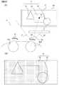
図3(A)は、視野画像を説明するための概念図である。図3(A)では眼鏡レンズ9L、9Rが眼鏡レンズ記述データに基づく仮想的なものとして示されている。被験者Sの眼球EbL、EbRは、表示部20を目視しており、右眼球EbRの光軸Axは表示部20の中心Oを通っている。表示部20には視野画像21が表示されており、視野画像21には3つの仮想物体V(Vo,V1,V2)の画像が示されている。眼鏡レンズ9L、9Rは、左眼球EbLおよび右眼球EbRの前方の眼鏡レンズ位置に仮想的に配置されている。 FIG. 3A is a conceptual diagram for explaining a field image. In FIG. 3A, the
図3(A)において、破線L1,L2は右眼球EbRからの、眼鏡レンズ9Rを通して見ることのできる視野の範囲の左端および右端をそれぞれ模式的に示している。つまり、被験者Sは、表示部20の左側が眼鏡レンズ9Rを通して目視できる範囲であるが、表示部20の右側の一部については、眼鏡レンズ9Rを通して目視できない範囲となっている。 In FIG. 3A, the broken lines L1 and L2 schematically show the left end and the right end of the visual field range that can be seen through the
図3(B)は、図3(A)の場合の視野画像21を模式的に示した図である。視野画像21のハッチングがされた部分22は、被験者Sが仮想的な眼鏡レンズ9Rを通して表示部20を目視した場合の視野の画像である。視野画像21のハッチングされていない部分23は、被験者Sが仮想的な眼鏡レンズ9Rを通さずに表示部20を目視した場合の視野の画像である。図3(A)で眼鏡レンズ9Rを通しては目視できない視野画像21の右側の一部の領域については、被験者Sの裸眼による視野の画像が表示される。このように、画像作成部43は、被験者Sの視野における眼鏡レンズ9L、9Rの領域に基づいて、視野画像21を作成する。
なお、視野画像21は、左眼または右眼のいずれか一方の視野に基づいて作成してもよいし、両眼の視野についての視野画像を利き目の度合等に基づいて局所的にずらして合成した合成画像として作成してもよい。また、本実施形態ではパラメータ算出部42が眼の位置を算出し、当該眼の位置を視点に画像作成部43が視野画像を作成しているが、視点は厳密に眼の位置に合わせなくともよく、例えば両眼の中央の位置を視点位置とする等、適宜設定することができる。FIG. 3B is a diagram schematically showing a
The
図4(A)は、図3(A)の状態から、被験者Sが頭部を右側に向けた状態を示す概念図である。図4(A)および図4(B)では、図3(A)および図3(B)と同一部分については同一の符号で参照し適宜説明を省略する。破線L1,L2でそれぞれ模式的に示される、右眼球EbRからの眼鏡レンズ9Rを通して見ることのできる視野の範囲の左端および右端は、表示部20に向かって右側に移動している。つまり、被験者Sは、表示部20の右側を眼鏡レンズ9Rを通して目視しているが、表示部20の左側の一部については、眼鏡レンズ9Rを通しては目視できない。 FIG. 4 (A) is a conceptual diagram showing a state in which the subject S has his head turned to the right from the state of FIG. 3 (A). In FIGS. 4 (A) and 4 (B), the same parts as those in FIGS. 3 (A) and 3 (B) are referred to by the same reference numerals, and the description thereof will be omitted as appropriate. The left and right ends of the field of view that can be seen through the
図4(B)は、図4(A)の場合の視野画像21を模式的に示した図である。図4(A)で眼鏡レンズ9Rを通しては目視できない左側の一部の領域については、被験者Sの裸眼による視野の画像が表示される。このように、画像作成部43は、被験者Sが眼の位置や顔の向きを変化させた場合には、それに伴う、視野における眼鏡レンズ9L、9Rの領域の変化に基づいて、視野画像21を作成する。 FIG. 4B is a diagram schematically showing a
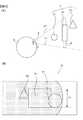
図5(A)は、視野画像21における画角の調整を説明するための概念図である。本実施形態では、表示部20の位置に仮想的な物体(以下、基準物体Voと呼ぶ)が配置されるように仮想空間を構築している。ここで、被験者Sと表示部20との間の距離が変化すると、本来は、被験者Sの視野における基準物体Voの大きさも変化するが、画像作成部43は、仮想物体間の見え方の関係を見易く表示するために、このような場合でも基準物体Voの視野画像21における大きさが略一定になるように視野画像21についての画角を調整する。 FIG. 5A is a conceptual diagram for explaining the adjustment of the angle of view in the
図5(A)では、仮想物体Vとして、基準物体Vo、仮想物体V1、仮想物体V2が模式的に示されている。仮想空間は、基準物体Voが表示部20(破線で模式的に示した)の位置にあるものとして構築されている。被験者Sの視野は、被験者Sの眼Eから延びる一点鎖線L3およびL4にはさまれた領域として模式的に示した。 In FIG. 5A, a reference object Vo, a virtual object V1, and a virtual object V2 are schematically shown as the virtual object V. The virtual space is constructed assuming that the reference object Vo is at the position of the display unit 20 (schematically shown by the broken line). The visual field of subject S is schematically shown as a region sandwiched between the alternate long and short dash lines L3 and L4 extending from the eye E of subject S.
図5(B)は、図5(A)の場合に表示部20に表示される視野画像21を示す図である。図5(A)に示したように被験者S側から近い順に仮想物体V1、基準物体Vo、仮想物体V2の順でならんでいるため、視野画像21では仮想物体V1が最も手前にあり、仮想物体V2が最も後ろにあるように重ねて示されている。上記の通り、画像作成部43は、基準物体Voの大きさが略一定になるように視野画像21に対応する画角を調整するため、視野画像21における基準物体Voの幅Loは、視点位置が変わっても略一定となる。 FIG. 5B is a diagram showing a
図6(A)は、図5(A)の場合よりも被験者Sと表示部20との間の距離が短い場合を示す概念図である。図6(A)および図6(B)では、図5(A)および図5(B)と同一部分については同一の符号で参照し適宜説明を省略する。 FIG. 6A is a conceptual diagram showing a case where the distance between the subject S and the
図6(B)は、図6(A)の場合に表示部20に表示される視野画像21を示す図である。被験者Sと基準物体Voとの間の距離が図5(A)に示した場合に比べて短くなったため、被験者Sの視野における基準物体Voの大きさは本来大きくなるが、視野画像21における基準物体Voの大きさは略一定に調整され、従って視野画像21における基準物体Voの幅Loも略一定の値に保たれる。言い換えると、視野画像21における基準物体Voの大きさは、視点位置に関わらず、表示部20の表示画面の大きさと一定の関係にある。 FIG. 6B is a diagram showing a
画像作成部43は、視野画像21の作成において、被験者Sの眼の位置を視点位置として仮想空間を透視投影等によりレンダリングして投影画像を作成する。投影画像には、視野画像21と比較して、眼鏡レンズ9L,9R等により引き起こされる後述のぼけやゆがみが加えられていない。画像作成部43は、投影画像を作成する際に、視点位置に関係なく、表示部20の位置に配置された仮想物体Voの大きさが略一定になるように画角を調整する。言い換えると、画像作成部43は、視野画像21を作成する際に、視点位置に関係なく、視野画像21の画角が表示部20の表示画面の大きさと対応するように視野画像21を作成する。これにより、基準物体Voが大きく変化しないため、図5(B)や図6(B)に示されるように、仮想空間で基準物体Voの周囲にある仮想物体V1およびV2の見え方が視点位置によりどう変化するかを捉えやすくなる。 In creating the
画像作成部43は、投影画像を生成した後、仮想的な眼鏡レンズ9(眼鏡レンズ9L、9Rの左右を区別せずに指す場合、眼鏡レンズ9と呼ぶ)によって生じるゆがみを当該投影画像に加える画像処理を行う。 After generating the projected image, the
以下の実施形態において、「ゆがみ」とは、対象物が実際の形状とは異なる形状の像として認識されることを示し、縦横斜め等の任意の方向に対象物の像が伸縮することを主に指す。「ゆがみ」には、歪曲収差(distortion)を適宜含むが、本実施形態では、累進屈折力レンズのレンズ面のように、屈折力や非点収差が変化する面を通して対象物を見ることで起こる対象物の像の伸縮を主に想定している。 In the following embodiments, "distortion" means that the object is recognized as an image having a shape different from the actual shape, and the image of the object expands and contracts in any direction such as vertical, horizontal, and diagonal. Point to. The "distortion" appropriately includes distortion, but in the present embodiment, it occurs when the object is viewed through a surface in which the refractive power and astigmatism change, such as the lens surface of a progressive power lens. It is mainly assumed that the image of the object expands and contracts.
図7は、投影画像にゆがみを加える方法を説明するための概念図である。画像作成部43は、被験者Sが表示部20の表示画面S20を見る際の網膜と表示画面S20上の注視点Ptとを結ぶ光路を、回旋点Crから眼鏡レンズ9を透過し、眼鏡レンズ9の表面の点P1から注視点Ptまでを結ぶ光線追跡により算出する。回旋点Crの位置は、被験者Sの顔の形状に関する実測して得たデータを用いて設定することが好ましいが、眼鏡レンズ9の設計の際に想定されている回旋点の位置や、一般的な位置を用いて設定することができる。
なお、光線追跡の計算では網膜の各点に入射または網膜の各点から出射する光線を追跡してもよい。FIG. 7 is a conceptual diagram for explaining a method of adding distortion to a projected image. The
In the calculation of ray tracing, light rays incident on or emitted from each point of the retina may be traced.
画像作成部43は、眼鏡レンズ9の近傍に仮想的な面(以下、仮想面S1と呼ぶ)を設定する。仮想面S1は、被験者Sが正面を見たとき、または眼球Ebが眼鏡レンズ9のフィッティングポイントを見たときに、仮想面S1が表示画面S20と略平行、または眼球Ebの光軸Axと仮想面S1とが略垂直に交差するように設定されることが好ましい。画像作成部43は、仮想面S1上の一部の点P0を通る光線を光線追跡し、当該光線追跡の結果に基づいて算出された視野画像21の局所的なゆがみの度合に基づいて投影画像にゆがみを加える。 The
図8は、光線追跡による視野画像21の局所的なゆがみの算出方法を示す図である。説明をわかりやすくするため、仮想面S1および表示画面S20をx軸およびy軸(座標系902参照)に平行な格子状の線で分割して示し、表示画面S20の位置に、仮想空間を透視投影等によりレンダリングして得られた投影画像が配置されているものとする。当該投影画像には、仮想物体V3が含まれている。 FIG. 8 is a diagram showing a method of calculating the local distortion of the
画像作成部43は、光線追跡により、回旋点Crと仮想面S1上の点P01、P02、P03、P04等の座標点とを通る光線が入射する表示画面S20上のそれぞれ対応する点Pt1、Pt2、Pt3、Pt4等の位置を算出する。 The
画像作成部43は、図7に示したように、眼鏡レンズ9の表示部20側の面上の点P1から、点P1を通る光線が入射する表示画面S20上の点Ptへと向かうベクトルVtを光線追跡により算出する。点P1の座標をP1(x1,y1,z1)、点Ptの座標をPt(xt,yt,zt)、ベクトルVtをVt(vx,vy,vz)と表す(座標系901参照)と、aを(zt−z1)/vzとして、点Pのx座標xtとy座標ytは以下の式(1)のように表される。
xt=x1+a*vx、yt=y1+a*vy …式(1)
近似的に、zt−z1は被験者Sと表示部20との間の距離を用いることができるため、画像作成部43は、ベクトルVtに基づいて点Pのx座標xtとy座標ytを算出することができる。点P0と点P1は光線追跡により対応付けてもよいが、近似的に点P0のx座標およびy座標は点P1と同じ値を用いることができる。画像作成部43は、このような方法で点P01〜P04と点Pt1〜t4(図8)を対応付けることができる。
なお、眼鏡レンズ記述データまたは眼鏡レンズ位置データ等の眼鏡レンズ9に関するデータが、眼鏡レンズ9と紐づけて眼鏡レンズ9から表示部20へ向かう視線の方向を示すパラメータである上述のベクトルVtを含んでいてもよい。これにより、視野画像21を作成する際の演算処理の量を減らすことができる。As shown in FIG. 7, the
xx = x1 + a * vx, yt = y1 + a * vy ... Equation (1)
Approximately, since zt-z1 can use the distance between the subject S and the
It should be noted that the data related to the
図8では、仮想面S1上で点P01、P02、P03およびP04に囲まれた四角形の部分領域(二点鎖線で囲まれた領域)R1は、表示画面S20上で点Pt1、Pt2、Pt3、およびPt4に囲まれた部分領域R2に対応する。従って、画像作成部43は、仮想空間からレンダリングして得た投影画像の部分領域R2に対応する部分が、部分領域R1に含まれるように当該投影画像を伸縮する。図8の例では、表示画面S20上の部分領域R2が、y軸方向の幅がより小さい仮想面S1上の部分領域R1に対応することに基づいて、部分領域R2に対応する仮想物体V3の画像が、y軸方向に縮むように加工されることになる。言い換えると、光線追跡を行っていない眼鏡レンズ9上の点については、線形補間により定められたゆがみが加えられることになる。 In FIG. 8, the rectangular partial region (region surrounded by the alternate long and short dash line) R1 surrounded by the points P01, P02, P03 and P04 on the virtual surface S1 is the points Pt1, Pt2, Pt3 on the display screen S20. And corresponds to the partial region R2 surrounded by Pt4. Therefore, the
画像作成部43は、上述のように、被験者Sの眼から出射された光の、眼鏡レンズ9からの出射方向に基づいて、視野画像21における局所的なゆがみの方向や量を算出し、当該ゆがみを加えた視野画像21を作成する。これにより、画像作成部43は、眼鏡レンズ9の面に対応する全ての座標点について光線追跡を行わなくともゆがみを加えた視野画像21を作成することができる。従って、画像作成部43は、高速にゆがみを加えた視野画像21を作成することが可能となり、当該視野画像21からなる、より高いフレームレートの動画像を作成することが可能となる。 As described above, the
画像作成部43は、仮想空間をレンダリングして得た、視点位置から仮想空間を見た投影画像にゆがみを加えた後、仮想的な眼鏡レンズ9によって生じるぼけを当該投影画像に加える画像処理を行う。 The
以下の実施形態において、「ぼけ」とは、対象物を、当該対象物を視認するのに適切な分解能よりも低い分解能で認識した際に起こる対象物のディテールの消失を指す。より具体的には、「ぼけ」は、主に、デフォーカス状態(ピントがずれた状態)で撮像された画像や、対象物からの光の眼光学系の光学的収差による結像面が網膜とずれている際に認識される像で見られる輪郭やパターンの不明瞭化を指す。 In the following embodiments, "blurring" refers to the loss of detail in an object that occurs when the object is recognized with a resolution lower than the resolution appropriate for visually recognizing the object. More specifically, "blurring" is mainly an image captured in a defocused state (out of focus state) or an image plane due to optical aberration of the ocular optical system of light from an object on the retina. It refers to the obscurity of contours and patterns seen in the image recognized when it is out of alignment.
図9(A)および図9(B)は、画像にぼけを加える方法の一例を説明するための概念図である。図9(A)は、ぼけを加える前の画像Boから、ぼけに方向依存性の無い場合のぼけ画像B1を作成する際の画像処理を示す概念図である。この場合のぼけ画像B1は、例えば、非点収差がない場合の屈折力エラーによるぼけに基づいて作成したものである。 9 (A) and 9 (B) are conceptual diagrams for explaining an example of a method of adding blur to an image. FIG. 9A is a conceptual diagram showing image processing when creating a blurred image B1 when there is no direction dependence in the blur from the image Bo before adding the blur. The blurred image B1 in this case is created based on, for example, blurring due to a refractive power error when there is no astigmatism.
ぼけ画像B1は、画像中の各画素の画素値を、点像分布関数(Point Spread Function;PSF)をカーネルとして畳み込み積分することにより取得することができる。丸の中にXが描かれた記号は畳み込み積分を示す。ぼけを加える前の画像Boを方向依存性の無い点像分布関数PSF1により畳み込み積分すると、ぼけ画像B1に示すように各点が一様にぼけたような画像が得られる。ぼけ画像B1は非方向依存的なぼけ画像B1となる。畳み込み積分は、コンピュータによる離散的な計算においては、3×3、5×5等の行列(図10参照、以下、ぼけカーネル行列と呼ぶ)をカーネルとした畳み込み処理を行うことに相当する。 The blurred image B1 can be obtained by convolving and integrating the pixel values of each pixel in the image by using the point spread function (PSF) as a kernel. The symbol with an X in the circle indicates the convolution integral. When the image Bo before adding the blur is convolved and integrated by the point spread function PSF1 having no direction dependence, an image in which each point is uniformly blurred is obtained as shown in the blurred image B1. The blurred image B1 becomes a non-directional dependent blurred image B1. The convolution integral corresponds to performing a convolution process using a matrix such as 3 × 3, 5 × 5 (see FIG. 10, hereinafter referred to as a blurred kernel matrix) as a kernel in discrete calculation by a computer.
図9(B)は、ぼけに方向依存性がある場合のぼけ画像B2を作成する際の画像処理を示す概念図である。この場合のぼけ画像B2は、非点収差と屈折力エラーとによるぼけを模したものである。 FIG. 9B is a conceptual diagram showing image processing when creating a blurred image B2 when the blur has direction dependence. The blur image B2 in this case imitates the blur caused by astigmatism and the refractive power error.
ぼけを加える前の像Boを方向依存性(斜め45度方向)を有する点像分布関数PSF2により畳み込み積分すると、ぼけ画像B2に示すように各点が斜め45度方向に向かってより強くぼけた画像が得られる。ぼけ画像B2は方向依存的なぼけ画像B2となる。 When the image Bo before blurring was convolved and integrated by the point spread function PSF2 having a direction dependence (diagonal 45 degree direction), each point was more strongly blurred toward the diagonal 45 degree direction as shown in the blurred image B2. An image is obtained. The blurred image B2 becomes a direction-dependent blurred image B2.
図9(A)(B)の例では、ぼけを加える前の画像Boの全体に対し同じ点像分布関数を用いて畳み込み処理をしてぼけ画像B1,B2を作成する例を示した。しかし、画像作成部43は、投影画像の各位置において、適宜異なる点像分布関数に対応したぼけカーネル行列をカーネルとして畳み込み処理を行い視野画像21を作成することができる。 In the example of FIGS. 9A and 9B, an example is shown in which the entire image Bo before blurring is subjected to a convolution process using the same point image distribution function to create blurred images B1 and B2. However, the
画像作成部43は、入力部31若しくは通信部32を介して、または記憶部33に記憶された被験者Sの過去のデータから、被験者Sの眼鏡レンズの処方データを参照し、球面度数、乱視度数および乱視軸のデータ等の眼の屈折力に関するデータを取得する。画像作成部43は、取得した眼の屈折力に関するデータと、表示部20の中心O(図1)等の所定の位置を見る際の眼鏡レンズ9の屈折力から、被験者Sが表示部20に焦点を合わせる際のぼけカーネル行列を設定する。 The
画像作成部43は、被験者Sの調節力を取得する。被験者Sの調節力は、例えば、調節力の大きさに基づいて、ディオプタ(D)等を単位とした数値(以下、調節力パラメータと呼ぶ)により設定される。調節力パラメータは、ユーザにより入力部31から入力されてもよいし、被験者Sの処方データにおける年齢から既知のデータに基づいて設定してもよいし、処方データが累進屈折力レンズ等の場合は加入度等に基づいて算出してもよい。 The
画像作成部43は、被験者Sの球面度数、乱視度数および乱視軸のデータから計算される屈折力と、被験者Sが表示部20の中心O等を目視する際の眼鏡レンズ9の屈折力および非点収差と、被験者Sと表示部20との間の距離と、仮想空間の物体の位置と、調節力パラメータによる調節力とに基づいて、光線追跡により収差量を求め、ぼけカーネル行列Kを設定する。調節力が大きいと、眼の屈折力の変化量が大きいため、眼の屈折力の変化量に合わせて例えば0.25D等の任意の屈折力毎に異なるぼけカーネル行列Kを設定する。 The
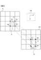
図10は、屈折力が変化したときのぼけカーネル行列Kの変化を示す概念図である。被験者Sが調節により眼球Ebの屈折力を大きくしていくと、ぼけカーネル行列Kは、ぼけカーネル行列K1、K2、K3、K4、K5、K6の順に変化していく。図10ではぼけカーネル行列Kは3×3の場合を示しており、ぼけカーネル行列K1,K2,K3,K4,K5およびK6にそれぞれ対応する点像分布関数PSF1,PSF2,PSF3,PSF4,PSF5およびPSF6を重ねて模式的に示している。 FIG. 10 is a conceptual diagram showing a change in the blurred kernel matrix K when the refractive power changes. When the subject S increases the refractive power of the eyeball Eb by accommodation, the blurred kernel matrix K changes in the order of the blurred kernel matrices K1, K2, K3, K4, K5, and K6. FIG. 10 shows the case where the blurred kernel matrix K is 3 × 3, and the point image distribution functions PSF1, PSF2, PSF3, PSF4, PSF5 and K6 corresponding to the blurred kernel matrices K1, K2, K3, K4, K5 and K6, respectively. The PSF6 is shown schematically overlaid.
ぼけカーネル行列K4は、中央の数値が1.00となっており、ぼけを生じないカーネルとなる。被験者Sは、注視点において、調節力の範囲内で、最もぼけを生じない屈折力に調節を行うと考えられる。従って、画像作成部43は、被験者Sの調節力に基づいて実現可能な屈折力に基づいたぼけカーネル行列Kのうちで、最もぼけの少ない、すなわちぼけカーネル行列Kの最も中央の要素の数値の最も大きいぼけカーネル行列K4を、表示部20の中心Oに対応する視野画像21の位置のカーネルとして設定する。画像作成部43は、当該ぼけカーネル行列K4に対応する被験者Sの屈折力(以下、調節後屈折力と呼ぶ)の値を取得する。 The blur kernel matrix K4 has a central value of 1.00, and is a kernel that does not cause blur. It is considered that the subject S adjusts the refractive power that causes the least blur within the range of the accommodation force at the gazing point. Therefore, the
画像作成部43は、想定されるぼけカーネル行列Kのうちで、最も中央の要素の数値が最も大きい値をとるぼけカーネル行列Kが複数ある場合は、最も調節量の小さい場合に対応するぼけカーネル行列Kを表示部20の中心Oに対応する視野画像21の位置のカーネルとして設定する。 When there are a plurality of blurred kernel matrices K having the largest numerical value of the central element among the assumed blurred kernel matrices K, the
画像作成部43は、取得した調節後屈折力、乱視度数および乱視軸と、仮想空間内の各点の位置と、当該各点を目視する際に視線が透過する眼鏡レンズ9の位置の屈折力および非点収差とに基づいて、視野画像21の各点のぼけカーネル行列Kを算出する。
なお、視野画像21において、眼鏡レンズ9を通さずに見る部分については、上述のようにして得た被験者Sの調節力に基づいてぼけカーネル行列Kを算出してもよいし、被験者Sの裸眼の検眼データに基づいてぼけを加えてもよい。The
In the
画像作成部43は、仮想空間に配置された仮想物体V上の各点から出射され、眼鏡レンズ9を透過し、眼Eの網膜に入射する光線を光線追跡する。ここで、画像作成部43は、上記で得られた調節後調節力に基づいて眼球モデルにおけるレンズのパラメータを設定する。眼球モデルは、適宜過去に測定された眼球のデータを基に構築されたものを利用してよい。画像作成部43は、光線追跡において網膜の各点に入射する各光線の収束位置から、視野画像21の各点における収差量を算出することができる。画像作成部43は、視野画像21の各点における収差量に基づいて当該各点のぼけカーネル行列Kを設定する。
なお、眼鏡レンズ9の各点において眼鏡レンズ形状データおよび眼鏡レンズ位置データ等に基づいて光線追跡により予め算出されたぼけカーネル行列Kが眼鏡レンズ9と紐づけられたデータを、画像作成部43が取得する構成にしてもよい。The
It should be noted that the
視野画像21の各点に対応するぼけカーネル行列Kが設定されたら、画像作成部43は、これらのぼけカーネル行列Kをカーネルとして、上述したゆがみが加えられた画像の画素値を示す行列に畳み込み処理を行い、視野画像21を作成する。
なお、仮想空間を視点位置に基づいてレンダリングして得た2次元画像に、まずぼけカーネル行列Kを用いた上述の方法によりぼけを加えた後、ゆがみを加えてもよい。When the blurred kernel matrix K corresponding to each point of the
It should be noted that the two-dimensional image obtained by rendering the virtual space based on the viewpoint position may be first blurred by the above-mentioned method using the blur kernel matrix K, and then distorted.
表示制御部44(図1)は、画像作成部43により作成された視野画像21の表示部20の表示画面への表示を制御する。表示制御部44は、撮像部10が順次撮像した被験者画像Isに基づいて、画像作成部43が順次作成した視野画像21を、順次表示部20に表示する。 The display control unit 44 (FIG. 1) controls the display of the
被験者Sは、表示部20に表示された視野画像21を様々な位置から目視ししながら、仮想的な眼鏡レンズ9を通して表示部20の位置にある基準物体Vo等がどのように見えるかを体験することができる。画像作成装置1は、被験者Sがこのような体験に基づいて装用する眼鏡レンズを選択するための眼鏡レンズ選択システムとして構成することができる。 Subject S experiences how the reference object Vo or the like at the position of the
さらに、被験者Sは、仮想的な眼鏡レンズ9を通して、仮想空間において基準物体Voの周囲にある他の仮想物体V1,V2がどのように視野に映るかを体験することができる。眼鏡レンズの装用者は、累進屈折力レンズにおける注視点から離れた点での見え方や、単焦点レンズにおけるレンズの辺縁部における見え方を特に気にする場合がある。本実施形態の画像作成装置1は、眼鏡レンズを装用する場合のこのような見え方のシミュレーションを行う装置として特に好適である。 Further, the subject S can experience how other virtual objects V1 and V2 around the reference object Vo are reflected in the field of view in the virtual space through the
図11は、本実施形態の画像作成装置を用いた画像作成方法の流れを示すフローチャートである。ステップS1001において、被験者Sが表示部20に表示される画像を無理なく見えるように、被験者Sが矯正レンズを装用する等により被験者Sの視力が矯正される。矯正レンズとしては、被験者Sが普段装用している眼鏡レンズでもよい。ステップS1001が終了したら、ステップS1003が開始される。ステップS1003において、画像作成部43は、仮想空間に配置される仮想物体Vを設定し、仮想空間を構築する。ステップS1003が終了したらステップS1005が開始される。 FIG. 11 is a flowchart showing a flow of an image creation method using the image creation device of the present embodiment. In step S1001, the visual acuity of the subject S is corrected by the subject S wearing a corrective lens or the like so that the subject S can see the image displayed on the
ステップS1005において、画像作成部43は、眼鏡レンズ記述データを取得し、被験者Sが仮想的な眼鏡レンズ9を装用した際の被験者Sに対する眼鏡レンズの相対位置を決定する。ステップS1005が終了したら、ステップS1007が開始される。
なお、ステップS1001、1003および1005は、異なる順番で行われてもよい。In step S1005, the
In addition, steps S1001, 1003 and 1005 may be performed in a different order.
ステップS1007において、撮像部10は、表示部20を目視する被験者Sを撮像し、特徴検出部41は、撮像により得られた被験者画像Isから特徴Fを検出する。ステップS1007が終了したら、ステップS1009が開始される。ステップS1009において、パラメータ算出部42は、検出された特徴Fの位置および検出された特徴Fの間の距離に基づいて、被験者Sと表示部20との間の距離および被験者Sの顔の向きを算出する。ステップS1009が終了したら、ステップS1011が開始される。 In step S1007, the
ステップS1011において、画像作成部43は、被験者Sと表示部20との間の距離および顔の向きに基づいて、被験者Sが眼鏡レンズ9を通して表示部20を目視した場合の仮想的な視野の画像(視野画像21)を作成する。ステップS1011が終了したら、ステップS1013に進む。 In step S1011, the
ステップS1013において、制御部40は、ユーザにより眼鏡レンズ9を変更する変更指示が入力されたか否かを判定する。変更指示が入力された場合、制御部40はステップS1013を肯定判定してステップS1005に戻る。変更指示が入力されていない場合、制御部40はステップS1013を否定判定してステップS1015に進む。 In step S1013, the
ステップS1015において、制御部40は、視野画像21の作成を終了する終了指示が入力されたか否かを判定する。終了指示が入力された場合、制御部40はステップS1015を肯定判定してステップS1017に進む。終了指示が入力されていない場合、制御部40はステップS1015を否定判定してステップS1007に戻る。終了指示の入力がされるまでステップS1007〜ステップS1015が繰り返され、視野画像21が動画像として連続的に表示されることになる。 In step S1015, the
ステップS1017において、ユーザは、視野画像21を目視した被験者Sの応答を取得し、当該応答に基づいて被験者Sが装用する眼鏡レンズが選択される。例えば、眼鏡店において、被験者Sは、購入を検討している眼鏡レンズを仮想的に装用した場合の視野画像21を目視する。この場合の視野画像21は、被験者Sが予め得た処方データに基づいた球面度数、乱視度数および加入度等を有する仮想的な眼鏡レンズを通して見る際の画像であり、視野画像21は、当該眼鏡レンズにより矯正された視力で表示部20を目視する際の仮想的な画像となる。眼鏡店の販売員であるユーザは、被験者Sから、視野画像21を目視した印象を被験者Sから聞き取る。当該印象に基づいて被験者Sが購入する眼鏡レンズが選択され、不図示の眼鏡レンズ発注装置に入力される。
なお、画像作成装置1に、被験者Sが装用する眼鏡レンズの情報が入力され、画像作成装置1が発注を行う構成にしてもよい。また、被験者Sが、視野画像21を目視した後、自分で入力部31を介して装用する(購入する)眼鏡レンズを入力してもよい。ステップS1017が終了したら、ステップS1019が開始される。In step S1017, the user acquires the response of the subject S who visually observes the
In addition, the
ステップS1019において、眼鏡レンズ発注装置は、被験者Sが装用する眼鏡レンズを発注し、眼鏡レンズを受注した不図示の眼鏡レンズ受注装置は、不図示の眼鏡レンズ加工機に眼鏡レンズを製造させる。ステップS1019が終了したら、処理を終了する。 In step S1019, the spectacle lens ordering device orders the spectacle lens to be worn by the subject S, and the spectacle lens ordering device (not shown) for which the spectacle lens is ordered causes the spectacle lens processing machine (not shown) to manufacture the spectacle lens. When step S1019 is completed, the process ends.
上述の実施の形態によれば、次の作用効果が得られる。
(1)本実施形態の画像作成装置は、表示部20を目視する被験者Sを撮像した被験者画像Isから、特徴Fを検出する特徴検出部41と、検出された特徴Fの位置および/または検出された特徴Fの間の距離に基づいて、被験者Sと表示部20との間の距離および被験者Sの顔の向き を算出するパラメータ算出部43と、被験者Sと表示部20との間の距離および顔の向きに基づいて、被験者Sが眼鏡レンズ9を通して表示部20を目視した場合の視野画像21を作成する画像作成部43と、視野画像21を表示部20に表示させる表示制御部44とを備える。これにより、被験者Sを撮像した画像における特徴Fを利用した効率的な処理により、被験者Sに眼鏡レンズ9を通した見え方を体験させることができる。また、距離画像センサやヘッドマウントディスプレイ等の特殊な装置を用いなくても、一般的なカメラで撮像した画像だけで被験者Sに眼鏡レンズ9を通した見え方をリアルに体験させることができる。According to the above-described embodiment, the following effects can be obtained.
(1) The image creation device of the present embodiment has a
(2)本実施形態の画像作成装置において、パラメータ算出部42は、検出された特徴Fの位置および/または検出された特徴Fの間の距離に基づいて、被験者Sの眼の位置を算出し、画像作成部43は、眼の位置、被験者Sと表示部20との間の距離および顔の向きに基づいて、被験者Sが眼の位置から眼鏡レンズ9を通して表示部20を目視した場合の視野画像21を作成する。これにより、より精密な視点位置が得られ、被験者Sに眼鏡レンズ9を通したより実際に近い見え方を体験させることができる。(2) In the image creating apparatus of the present embodiment, the
(3)本実施形態の画像作成装置において、画像作成部43は、被験者Sが表示部20の位置にある仮想的な物体(基準物体Vo)を目視する場合の、視野画像21を作成する。これにより、被験者Sに、表示部20の位置にある物体がどう見えるかを、わかりやすく体験させることができる。(3) In the image creation device of the present embodiment, the
(4)本実施形態の画像作成装置において、画像作成部43は、基準物体Voを含む3次元の仮想空間を構築し、被験者Sの眼の位置に関わらず、視野画像21の画角を、表示部20の表示画面S20の大きさに対応させる。これにより、大きさや位置が把握しやすい基準物体Voを基準に他の仮想物体Vが表示されるため、被験者Sは立体的な感覚を得やすかったり、注視点以外の位置の見え方を把握しやすい。(4) In the image creation device of the present embodiment, the
(5)本実施形態の画像作成装置において、画像作成部43は、眼Eから出射された光の、眼鏡レンズ9からの出射方向に基づいて、眼鏡レンズ9による局所的なゆがみを算出する。これにより、局所的なゆがみを用いて視野画像21の各部分を処理することにより、高速に視野画像21を作成することができる。(5) In the image creation device of the present embodiment, the
(6)本実施形態の画像処理装置において、画像作成部43は、仮想空間に配置された仮想物体V上の点から出射され、眼鏡レンズ9を透過し、眼Eの網膜に入射する光線を光線追跡した結果に基づいて、網膜における収差量を算出し、この収差量に基づいた畳み込み計算によりぼけを含む視野画像21を作成する。これにより、被験者Sは、眼鏡レンズ9の各点に対応するぼけが考慮された、眼鏡レンズ9を通したより実際に近い見え方を体験することができる。(6) In the image processing apparatus of the present embodiment, the
(7)本実施形態の画像処理装置において、被験者Sは、調節力、年齢、および/または処方データに基づいたパラメータ等に基づいて収差量を算出する。これにより、被験者Sは、被験者Sの調節力が考慮された、眼鏡レンズ9を通したより実際に近い見え方を体験することができる。(7) In the image processing apparatus of the present embodiment, the subject S calculates the amount of aberration based on accommodation power, age, and / or parameters based on prescription data. As a result, the subject S can experience a more realistic appearance through the
(8)本実施形態の画像処理装置において、画像作成部43は、被験者Sと表示部20との間の距離に基づいて畳み込み計算のカーネルであるぼけカーネル行列を変化させる。これにより、少ない処理でぼけカーネル行列を設定し、高速に視野画像21にぼけを加えることができる。(8) In the image processing apparatus of the present embodiment, the
(9)本実施形態の画像処理装置において、パラメータ算出部42は、被験者Sの処方データおよび/または眼鏡レンズを装用した被験者Sの実測値に基づいて、視野画像21を作成する際の眼鏡レンズ9の位置および姿勢を算出する。これにより、被験者Sに合った眼鏡レンズ位置を用いて、被験者Sにより実際に近い見え方を体験させることができる。(9) In the image processing apparatus of the present embodiment, the
(10)本実施形態の画像処理装置において、特徴検出部41は、特徴Fを、被験者Sの顔に対応する、被験者画像Isの一部分から検出する。これにより、被験者Sの顔を撮像した画像から被験者Sと表示部20との間の距離等のパラメータを算出し、効率的に処理ができる。また、ヘッドマウントディスプレイ等の被験者の眼前にレンズが配置された装置を必要としないため、このようなレンズによる収差の影響を考慮する必要が無い。(10) In the image processing apparatus of the present embodiment, the
(11)本実施形態の画像処理方法では、表示部20を目視する被験者Sを撮像した被験者画像Isから、複数の特徴を検出し、検出された特徴Fの位置および/または検出された特徴Fの間の距離に基づいて、被験者Sと表示部20との間の距離および被験者Sの顔の向きを算出し、被験者Sと表示部20との間の距離および顔の向きに基づいて、被験者Sが眼鏡レンズ9を通して表示部20を目視した場合の視野画像21を作成し、視野画像21を表示部20に表示させる。これにより、被験者Sを撮像した画像における特徴Fを利用した効率的な処理により、被験者Sに眼鏡レンズ9を通した見え方を体験させることができる。(11) In the image processing method of the present embodiment, a plurality of features are detected from the subject image Is obtained by capturing the subject S who visually observes the
次のような変形例も本発明の範囲内であり、上述の実施形態と組み合わせることが可能である。上述の実施形態と同一の参照符号で示された部分は、同一の機能を有し適宜説明を省略する。
(変形例1)
上述の実施形態では、パラメータ算出部42は、被験者Sの特徴Fから、瞳孔間距離PDを用いて被験者Sと表示部20との間の距離等のパラメータを算出した。しかし、被験者Sが、長さが既知の部分を有する部材を頭部に装着し、パラメータ算出部42は被験者画像Is中の当該部分の長さを用いて被験者Sと表示部20との間の距離等のパラメータを算出してもよい。例えば、被験者Sが表示部20を目視する際に装用する矯正レンズおよび/または当該矯正レンズのフレーム等に、特徴検出部41が特徴Fとして検出可能なマーク等を付しておくことができる。The following modifications are also within the scope of the present invention and can be combined with the above embodiments. The parts indicated by the same reference numerals as those in the above-described embodiment have the same functions, and the description thereof will be omitted as appropriate.
(Modification example 1)
In the above-described embodiment, the
このように、特徴検出部41が、特徴Fを、被験者Sの頭部に配置された部材に対応する、被験者画像Isの一部分から検出する構成にすることができる。これにより、検出しやすい特徴に基づいて、正確に被験者Sと表示部20との間の距離等のパラメータを算出することができる。 In this way, the
(変形例2)
上述の実施形態では、画像作成装置1は表示部20を1つ備える構成としたが、複数の表示部20を備える構成としてもよい。この場合、複数の表示部20は、被験者Sからそれぞれ異なる距離に配置されることが好ましい。例えば、複数の表示部20は、被験者Sから、遠距離(1m以上等、適宜設定される)、近距離(50cm未満等、適宜設定される)、および遠距離と近距離との間の中間距離から選択される少なくとも2つ以上の距離に配置されることが好ましい。これにより、被験者Sに異なる距離の対象物の間で視線を移動させた際の見え方を体験させたり等、より詳しく仮想的な眼鏡レンズを通した見え方を体験させることができる。(Modification 2)
In the above-described embodiment, the
(変形例3)
上述の実施形態において、表示部20が3次元ディスプレイを含んで構成されてもよい。この場合、画像作成部43は、被験者Sの左眼の位置を視点とした視野画像21である左眼視野画像と、被験者Sの右眼の位置を視点とした視野画像21である右眼視野画像とを作成する。被験者Sが表示部20の3次元ディスプレイを目視する際には、特殊な光学特性を備えた眼鏡や視差障壁等を用いた方法により、被験者Sの左眼に左眼視野画像を、被験者Sの右眼に右眼視野画像を提示される。これにより、被験者Sは、視野画像21を見る際に立体感を得ることができ、より現実に近い体験をすることができる。(Modification 3)
In the above-described embodiment, the
(変形例4)
上述の実施形態では、画像作成装置1は撮像部10を1つ備える構成としたが、複数の撮像部10を備える構成としてもよい。複数の撮像部10から得られた被験者画像Isを用いることにより、より正確に被験者Sと表示部20との間の距離や被験者Sの顔の向きを測定することができる。(Modification example 4)
In the above-described embodiment, the
(変形例5)
画像作成装置1の情報処理機能を実現するためのプログラムをコンピュータ読み取り可能な記録媒体に記録して、この記録媒体に記録された、上述した画像作成処理およびそれに関連する処理の制御に関するプログラムをコンピュータシステムに読み込ませ、実行させてもよい。なお、ここでいう「コンピュータシステム」とは、OS(Operating System)や周辺機器のハードウェアを含むものとする。また、「コンピュータ読み取り可能な記録媒体」とは、フレキシブルディスク、光磁気ディスク、光ディスク、メモリカード等の可搬型記録媒体、コンピュータシステムに内蔵されるハードディスク等の記憶装置のことをいう。さらに「コンピュータ読み取り可能な記録媒体」とは、インターネット等のネットワークや電話回線等の通信回線を介してプログラムを送信する場合の通信線のように、短時間の間、動的にプログラムを保持するもの、その場合のサーバやクライアントとなるコンピュータシステム内部の揮発性メモリのように、一定時間プログラムを保持するものを含んでもよい。また上記のプログラムは、前述した機能の一部を実現するためのものであってもよく、さらに前述した機能をコンピュータシステムにすでに記録されているプログラムとの組み合わせにより実現するものであってもよい。(Modification 5)
A program for realizing the information processing function of the
また、パーソナルコンピュータ(以下、PCと記載)等に適用する場合、上述した制御に関するプログラムは、CD−ROM、DVD−ROM等の記録媒体やインターネット等のデータ信号を通じて提供することができる。図12はその様子を示す図である。PC950は、CD−ROM953を介してプログラムの提供を受ける。また、PC950は通信回線951との接続機能を有する。コンピュータ952は上記プログラムを提供するサーバーコンピュータであり、ハードディスク等の記録媒体にプログラムを格納する。通信回線951は、インターネット、パソコン通信などの通信回線、あるいは専用通信回線などである。コンピュータ952はハードディスクを使用してプログラムを読み出し、通信回線951を介してプログラムをPC950に送信する。すなわち、プログラムをデータ信号として搬送波により搬送して、通信回線951を介して送信する。このように、プログラムは、記録媒体や搬送波などの種々の形態のコンピュータ読み込み可能なコンピュータプログラム製品として供給できる。 Further, when applied to a personal computer (hereinafter referred to as a PC) or the like, the above-mentioned control-related program can be provided through a recording medium such as a CD-ROM or a DVD-ROM or a data signal such as the Internet. FIG. 12 is a diagram showing the situation. The PC950 receives the program provided via the CD-ROM953. Further, the PC950 has a connection function with the
上述した情報処理機能を実現するためのプログラムとして、表示部20を目視する被験者Sを撮像した被験者画像Isから、複数の特徴Fを検出する特徴検出処理と、検出された特徴Fの位置および/または検出された特徴Fの間の距離に基づいて、被験者Sと表示部20との間の距離および被験者Sの顔の向きを算出するパラメータ算出処理と、被験者Sと表示部20との間の距離および顔の向きに基づいて、被験者Sが眼鏡レンズ9を通して表示部20を目視した場合の視野画像21を作成する画像作成処理と、視野画像21を表示部20に表示させる表示制御処理とを処理装置に行わせるためのプログラムが含まれる。 As a program for realizing the above-mentioned information processing function, a feature detection process for detecting a plurality of feature Fs from a subject image Is obtained by capturing a subject S who visually observes the
本発明は上記実施形態の内容に限定されるものではない。特に、上述の実施形態や変形例で示された事項は適宜組み合わせることができる。本発明の技術的思想の範囲内で考えられるその他の態様も本発明の範囲内に含まれる。 The present invention is not limited to the contents of the above embodiment. In particular, the items shown in the above-described embodiments and modifications can be combined as appropriate. Other aspects conceivable within the scope of the technical idea of the present invention are also included within the scope of the present invention.
1…画像作成装置、9,9L,9R…眼鏡レンズ、10…撮像部、20…表示部、21…視野画像、30…情報処理部、40…制御部、41…特徴検出部、42…パラメータ算出部、43…画像作成部、44…表示制御部、E…眼、Eb,EbL,EbR…眼球、F…特徴、K,K1,K2,K3,K4,K5,K6…ぼけカーネル行列、S…被験者、S1…仮想面、S20…表示画面、Vo…基準物体。1 ... Image creation device, 9, 9L, 9R ... Eyeglass lens, 10 ... Imaging unit, 20 ... Display unit, 21 ... Field image, 30 ... Information processing unit, 40 ... Control unit, 41 ... Feature detection unit, 42 ... Parameters Calculation unit, 43 ... Image creation unit, 44 ... Display control unit, E ... Eye, Eb, EbL, EbR ... Eyeball, F ... Features, K, K1, K2, K3, K4, K5, K6 ... Blurred kernel matrix, S ... Subject, S1 ... Virtual surface, S20 ... Display screen, Vo ... Reference object.
Claims (13)
Translated fromJapanese検出された前記特徴の位置および/または検出された前記特徴の間の距離に基づいて、前記被験者と前記表示装置との間の距離および前記被験者の顔の向きを算出するパラメータ算出部と、
前記被験者と前記表示装置との間の距離および前記顔の向きに基づいて、前記被験者が眼鏡レンズを通して前記表示装置を目視した場合の仮想的な視野の画像を作成する画像作成部と、
前記仮想的な視野の画像を前記表示装置に表示させる表示制御部と
を備える画像作成装置。A feature detection unit that detects features from an captured image of a subject who visually observes a display device,
A parameter calculation unit that calculates the distance between the subject and the display device and the orientation of the subject's face based on the detected position of the feature and / or the distance between the detected features.
An image creation unit that creates an image of a virtual field of view when the subject visually observes the display device through a spectacle lens based on the distance between the subject and the display device and the orientation of the face.
An image creation device including a display control unit that displays an image of the virtual field of view on the display device.
前記パラメータ算出部は、検出された前記特徴の位置および/または検出された前記特徴の間の距離に基づいて、前記被験者の眼の位置を算出し、
前記画像作成部は、前記眼の位置、前記被験者と前記表示装置との間の距離および前記顔の向きに基づいて、前記被験者が前記眼の位置から前記眼鏡レンズを通して前記表示装置を目視した場合の仮想的な視野の画像を作成する画像作成装置。In the image creating apparatus according to claim 1,
The parameter calculation unit calculates the position of the subject's eye based on the detected position of the feature and / or the distance between the detected features.
When the subject visually observes the display device from the position of the eye through the spectacle lens based on the position of the eye, the distance between the subject and the display device, and the orientation of the face. An image creation device that creates an image of the virtual field of view.
前記画像作成部は、前記被験者が前記表示装置の位置にある仮想的な物体を目視する場合の、前記仮想的な視野の画像を作成する画像作成装置。In the image creating apparatus according to claim 2,
The image creation unit is an image creation device that creates an image of the virtual field of view when the subject visually observes a virtual object at the position of the display device.
前記画像作成部は、前記物体を含む3次元の仮想空間を構築し、前記眼の位置に関わらず、前記仮想的な視野の画像の画角を、前記表示装置の表示画面の大きさに対応させる画像作成装置。In the image creating apparatus according to claim 3,
The image creation unit constructs a three-dimensional virtual space including the object, and makes the angle of view of the image in the virtual field of view correspond to the size of the display screen of the display device regardless of the position of the eye. Image creation device to make.
前記画像作成部は、前記眼から出射された光の、前記眼鏡レンズからの出射方向に基づいて、前記眼鏡レンズによる局所的なゆがみを算出する画像作成装置。In the image creating apparatus according to claim 4,
The image creation unit is an image creation device that calculates local distortion caused by the spectacle lens based on the direction in which the light emitted from the eye is emitted from the spectacle lens.
前記画像作成部は、前記仮想空間に配置された物体上の点から出射され、前記眼鏡レンズを透過し、前記眼の網膜に入射する光線を光線追跡した結果に基づいて、前記網膜における収差量を算出し、前記収差量に基づいた畳み込み計算によりぼけを含む前記仮想的な視野の画像を作成する画像作成装置。In the image creating apparatus according to claim 4 or 5.
The image creating unit emits light from a point on an object arranged in the virtual space, passes through the spectacle lens, and traces a light beam incident on the retina of the eye, and based on the result of ray tracing, the amount of aberration in the retina. An image creation device that creates an image of the virtual field including blur by a convolution calculation based on the amount of aberration.
前記画像作成部は、前記被験者の調節力、年齢、および処方データの少なくとも一つに基づいて前記収差量を算出する画像作成装置。In the image creating apparatus according to claim 6,
The image creation unit is an image creation device that calculates the amount of aberration based on at least one of the subject's accommodation power, age, and prescription data.
前記画像作成部は、前記被験者と前記表示装置との間の距離に基づいて前記畳み込み計算のカーネルを変化させる画像作成装置。In the image creating apparatus according to claim 6 or 7.
The image creation unit is an image creation device that changes the kernel of the convolution calculation based on the distance between the subject and the display device.
前記パラメータ算出部は、前記被験者の処方データおよび/または眼鏡レンズを装用した前記被験者の実測値に基づいて、前記仮想的な視野の画像を作成する際の眼鏡レンズの位置および姿勢を算出する画像作成装置。In the image creating apparatus according to any one of claims 1 to 8.
The parameter calculation unit calculates the position and orientation of the spectacle lens when creating an image of the virtual visual field based on the prescription data of the subject and / or the measured value of the subject wearing the spectacle lens. Creation device.
前記特徴検出部は、前記特徴を、前記被験者の顔、および前記被験者の頭部に配置された部材の少なくとも一つに対応する、前記撮像画像の一部分から検出する画像作成装置。In the image creating apparatus according to any one of claims 1 to 9.
The feature detection unit is an image creation device that detects the feature from a part of the captured image corresponding to at least one of the members arranged on the face of the subject and the head of the subject.
前記表示装置と、
前記表示装置を目視する被験者を撮像する撮像部と
を備える眼鏡レンズ選択システム。The image creation device according to any one of claims 1 to 10.
With the display device
A spectacle lens selection system including an imaging unit that captures an image of a subject who visually observes the display device.
検出された前記特徴の位置および/または検出された前記特徴の間の距離に基づいて、前記被験者と前記表示装置との間の距離および前記被験者の顔の向きを算出することと、
前記被験者と前記表示装置との間の距離および前記顔の向きに基づいて、前記被験者が眼鏡レンズを通して前記表示装置を目視した場合の仮想的な視野の画像を作成することと、
前記仮想的な視野の画像を前記表示装置に表示させることと
を備える画像作成方法。Detecting features from captured images of subjects who visually check the display device,
To calculate the distance between the subject and the display device and the orientation of the subject's face based on the detected position of the feature and / or the distance between the detected features.
Creating a virtual visual field image when the subject visually observes the display device through a spectacle lens based on the distance between the subject and the display device and the orientation of the face.
An image creation method comprising displaying an image of the virtual field of view on the display device.
検出された前記特徴の位置および/または検出された前記特徴の間の距離に基づいて、前記被験者と前記表示装置との間の距離および前記被験者の顔の向きを算出するパラメータ算出処理と、
前記被験者と前記表示装置との間の距離および前記顔の向きに基づいて、前記被験者が眼鏡レンズを通して前記表示装置を目視した場合の仮想的な視野の画像を作成する画像作成処理と、
前記仮想的な視野の画像を前記表示装置に表示させる表示制御処理と
を処理装置に行わせるためのプログラム。Feature detection processing that detects features from captured images of subjects who visually check the display device,
Parameter calculation processing for calculating the distance between the subject and the display device and the orientation of the subject's face based on the detected position of the feature and / or the distance between the detected features.
An image creation process that creates an image of a virtual visual field when the subject visually observes the display device through a spectacle lens based on the distance between the subject and the display device and the orientation of the face.
A program for causing a processing device to perform a display control process for displaying an image of the virtual field of view on the display device.
Applications Claiming Priority (1)
| Application Number | Priority Date | Filing Date | Title |
|---|---|---|---|
| PCT/JP2018/000528WO2019138515A1 (en) | 2018-01-11 | 2018-01-11 | Image forming device, eyeglass lens selection system, image forming method, and program |
Publications (2)
| Publication Number | Publication Date |
|---|---|
| JPWO2019138515A1true JPWO2019138515A1 (en) | 2021-01-28 |
| JP7241702B2 JP7241702B2 (en) | 2023-03-17 |
Family
ID=67219474
Family Applications (1)
| Application Number | Title | Priority Date | Filing Date |
|---|---|---|---|
| JP2019564219AActiveJP7241702B2 (en) | 2018-01-11 | 2018-01-11 | Image creation device, spectacle lens selection system, image creation method and program |
Country Status (5)
| Country | Link |
|---|---|
| EP (1) | EP3739376A4 (en) |
| JP (1) | JP7241702B2 (en) |
| CN (1) | CN111587397B (en) |
| CA (1) | CA3088248C (en) |
| WO (1) | WO2019138515A1 (en) |
Families Citing this family (3)
| Publication number | Priority date | Publication date | Assignee | Title |
|---|---|---|---|---|
| CN112914498B (en)* | 2021-01-22 | 2024-06-14 | 刘保松 | Auxiliary system and method for positioning astigmatism of eyeball |
| EP4098970B1 (en)* | 2021-05-31 | 2024-09-04 | Essilor International | Method for measuring a distance separating a camera from a reference object |
| CN115363517A (en)* | 2022-08-22 | 2022-11-22 | 上海炬佑智能科技有限公司 | Vision detection device and method |
Citations (10)
| Publication number | Priority date | Publication date | Assignee | Title |
|---|---|---|---|---|
| JPH07261724A (en)* | 1994-03-17 | 1995-10-13 | Hitachi Ltd | Selection method of character size or window size and display device using the selection method |
| JPH11183856A (en)* | 1997-12-19 | 1999-07-09 | Seiko Epson Corp | Eyeglass viewing experience apparatus, viewing experience method, and recording medium |
| JP2009230699A (en)* | 2008-03-25 | 2009-10-08 | Seiko Epson Corp | Simulation device, simulation program, and recording medium with the program recorded thereon |
| WO2009122684A1 (en)* | 2008-04-01 | 2009-10-08 | Yanase Takatoshi | Display system, display method, program, and recording medium |
| WO2010044383A1 (en)* | 2008-10-17 | 2010-04-22 | Hoya株式会社 | Visual field image display device for eyeglasses and method for displaying visual field image for eyeglasses |
| JP2010134460A (en)* | 2008-11-06 | 2010-06-17 | Seiko Epson Corp | Visual simulator for spectacle lens, visual simulation method for spectacle lens, and visual simulation program for spectacle lens |
| WO2013067230A1 (en)* | 2011-11-04 | 2013-05-10 | Balan Alexandru O | See-through display brightness control |
| JP2015522834A (en)* | 2012-03-27 | 2015-08-06 | ソニー株式会社 | Method and system for providing interaction information |
| US20170052393A1 (en)* | 2015-08-18 | 2017-02-23 | Viewitech Co., Ltd. | Eyeglass lens simulation system using virtual reality headset and method thereof |
| WO2017047178A1 (en)* | 2015-09-16 | 2017-03-23 | ソニー株式会社 | Information processing device, information processing method, and program |
Family Cites Families (4)
| Publication number | Priority date | Publication date | Assignee | Title |
|---|---|---|---|---|
| JPS6023801B2 (en) | 1972-12-31 | 1985-06-10 | 三菱農機株式会社 | Automatic load control device for mobile agricultural machinery, etc. |
| JP2011253042A (en)* | 2010-06-02 | 2011-12-15 | Seiko Epson Corp | Selection method for spectacle lens and selection system for spectacle lens |
| JP6322986B2 (en)* | 2013-12-09 | 2018-05-16 | 富士通株式会社 | Image processing apparatus, image processing method, and image processing program |
| NZ773836A (en)* | 2015-03-16 | 2022-07-01 | Magic Leap Inc | Methods and systems for diagnosing and treating health ailments |
- 2018
- 2018-01-11CNCN201880086181.0Apatent/CN111587397B/enactiveActive
- 2018-01-11EPEP18899881.9Apatent/EP3739376A4/enactivePending
- 2018-01-11JPJP2019564219Apatent/JP7241702B2/enactiveActive
- 2018-01-11WOPCT/JP2018/000528patent/WO2019138515A1/ennot_activeCeased
- 2018-01-11CACA3088248Apatent/CA3088248C/enactiveActive
Patent Citations (10)
| Publication number | Priority date | Publication date | Assignee | Title |
|---|---|---|---|---|
| JPH07261724A (en)* | 1994-03-17 | 1995-10-13 | Hitachi Ltd | Selection method of character size or window size and display device using the selection method |
| JPH11183856A (en)* | 1997-12-19 | 1999-07-09 | Seiko Epson Corp | Eyeglass viewing experience apparatus, viewing experience method, and recording medium |
| JP2009230699A (en)* | 2008-03-25 | 2009-10-08 | Seiko Epson Corp | Simulation device, simulation program, and recording medium with the program recorded thereon |
| WO2009122684A1 (en)* | 2008-04-01 | 2009-10-08 | Yanase Takatoshi | Display system, display method, program, and recording medium |
| WO2010044383A1 (en)* | 2008-10-17 | 2010-04-22 | Hoya株式会社 | Visual field image display device for eyeglasses and method for displaying visual field image for eyeglasses |
| JP2010134460A (en)* | 2008-11-06 | 2010-06-17 | Seiko Epson Corp | Visual simulator for spectacle lens, visual simulation method for spectacle lens, and visual simulation program for spectacle lens |
| WO2013067230A1 (en)* | 2011-11-04 | 2013-05-10 | Balan Alexandru O | See-through display brightness control |
| JP2015522834A (en)* | 2012-03-27 | 2015-08-06 | ソニー株式会社 | Method and system for providing interaction information |
| US20170052393A1 (en)* | 2015-08-18 | 2017-02-23 | Viewitech Co., Ltd. | Eyeglass lens simulation system using virtual reality headset and method thereof |
| WO2017047178A1 (en)* | 2015-09-16 | 2017-03-23 | ソニー株式会社 | Information processing device, information processing method, and program |
Also Published As
| Publication number | Publication date |
|---|---|
| CN111587397A (en) | 2020-08-25 |
| CA3088248C (en) | 2022-10-04 |
| WO2019138515A1 (en) | 2019-07-18 |
| CN111587397B (en) | 2022-09-06 |
| EP3739376A4 (en) | 2021-09-01 |
| EP3739376A1 (en) | 2020-11-18 |
| CA3088248A1 (en) | 2019-07-18 |
| JP7241702B2 (en) | 2023-03-17 |
Similar Documents
| Publication | Publication Date | Title |
|---|---|---|
| JP7710586B2 (en) | Display system and method for determining alignment between a display and a user's eyes - Patents.com | |
| JP7679163B2 (en) | Display system and method for determining alignment between a display and a user's eyes - Patents.com | |
| JP7512505B2 (en) | Depth Plane Selection for Multi-Depth Planar Display Systems via User Categorization | |
| JP7699254B2 (en) | Display system and method for determining vertical alignment between left and right displays and a user's eyes - Patents.com | |
| JP7676400B2 (en) | SYSTEM AND METHOD FOR OPERATING A HEAD MOUNTED DISPLAY SYSTEM BASED ON USER IDENTIFICATION - Patent application | |
| JP7078540B2 (en) | Image creation device, image creation method, image creation program, spectacle lens design method and spectacle lens manufacturing method | |
| WO2017074662A1 (en) | Tracking of wearer's eyes relative to wearable device | |
| JP7241702B2 (en) | Image creation device, spectacle lens selection system, image creation method and program | |
| WO2016051429A1 (en) | Input/output device, input/output program, and input/output method | |
| US20250240400A1 (en) | Methods for controlling performance of extended reality display systems | |
| US12353622B2 (en) | Method and system for improving perfomance of an eye tracking system | |
| WO2016051430A1 (en) | Input/output device, input/output program, and input/output method |
Legal Events
| Date | Code | Title | Description |
|---|---|---|---|
| A625 | Written request for application examination (by other person) | Free format text:JAPANESE INTERMEDIATE CODE: A625 Effective date:20200916 | |
| RD03 | Notification of appointment of power of attorney | Free format text:JAPANESE INTERMEDIATE CODE: A7423 Effective date:20210423 | |
| RD04 | Notification of resignation of power of attorney | Free format text:JAPANESE INTERMEDIATE CODE: A7424 Effective date:20210715 | |
| RD04 | Notification of resignation of power of attorney | Free format text:JAPANESE INTERMEDIATE CODE: A7424 Effective date:20210812 | |
| A131 | Notification of reasons for refusal | Free format text:JAPANESE INTERMEDIATE CODE: A131 Effective date:20211026 | |
| A601 | Written request for extension of time | Free format text:JAPANESE INTERMEDIATE CODE: A601 Effective date:20211213 | |
| A521 | Request for written amendment filed | Free format text:JAPANESE INTERMEDIATE CODE: A523 Effective date:20220208 | |
| A131 | Notification of reasons for refusal | Free format text:JAPANESE INTERMEDIATE CODE: A131 Effective date:20220614 | |
| A601 | Written request for extension of time | Free format text:JAPANESE INTERMEDIATE CODE: A601 Effective date:20220815 | |
| A521 | Request for written amendment filed | Free format text:JAPANESE INTERMEDIATE CODE: A523 Effective date:20220908 | |
| A131 | Notification of reasons for refusal | Free format text:JAPANESE INTERMEDIATE CODE: A131 Effective date:20221115 | |
| A521 | Request for written amendment filed | Free format text:JAPANESE INTERMEDIATE CODE: A523 Effective date:20230105 | |
| TRDD | Decision of grant or rejection written | ||
| A01 | Written decision to grant a patent or to grant a registration (utility model) | Free format text:JAPANESE INTERMEDIATE CODE: A01 Effective date:20230207 | |
| A61 | First payment of annual fees (during grant procedure) | Free format text:JAPANESE INTERMEDIATE CODE: A61 Effective date:20230307 | |
| R150 | Certificate of patent or registration of utility model | Ref document number:7241702 Country of ref document:JP Free format text:JAPANESE INTERMEDIATE CODE: R150 |