JPWO2018230613A1 - Molding jig for dysphonia treatment device and method for bending front piece of dysphonia treatment device - Google Patents
Molding jig for dysphonia treatment device and method for bending front piece of dysphonia treatment deviceDownload PDFInfo
- Publication number
- JPWO2018230613A1 JPWO2018230613A1JP2019525489AJP2019525489AJPWO2018230613A1JP WO2018230613 A1JPWO2018230613 A1JP WO2018230613A1JP 2019525489 AJP2019525489 AJP 2019525489AJP 2019525489 AJP2019525489 AJP 2019525489AJP WO2018230613 A1JPWO2018230613 A1JP WO2018230613A1
- Authority
- JP
- Japan
- Prior art keywords
- piece
- holding
- molding jig
- treatment tool
- front surface
- Prior art date
- Legal status (The legal status is an assumption and is not a legal conclusion. Google has not performed a legal analysis and makes no representation as to the accuracy of the status listed.)
- Pending
Links
- 238000000465mouldingMethods0.000titleclaimsabstractdescription113
- 238000005452bendingMethods0.000titleclaimsabstractdescription30
- 238000000034methodMethods0.000titleclaimsdescription15
- 206010013952DysphoniaDiseases0.000titleclaimsdescription11
- 210000000534thyroid cartilageAnatomy0.000claimsabstractdescription48
- 230000037418vocal dysfunctionEffects0.000claimsabstractdescription23
- 238000003825pressingMethods0.000claimsdescription10
- 238000010586diagramMethods0.000abstract1
- 238000007493shaping processMethods0.000description16
- 230000000694effectsEffects0.000description11
- RTAQQCXQSZGOHL-UHFFFAOYSA-NTitaniumChemical compound[Ti]RTAQQCXQSZGOHL-UHFFFAOYSA-N0.000description6
- 239000010936titaniumSubstances0.000description6
- 229910052719titaniumInorganic materials0.000description6
- 238000003780insertionMethods0.000description5
- 230000037431insertionEffects0.000description5
- 239000000463materialSubstances0.000description5
- 239000002184metalSubstances0.000description5
- 229910052751metalInorganic materials0.000description5
- 238000012986modificationMethods0.000description4
- 230000004048modificationEffects0.000description4
- 229910001069Ti alloyInorganic materials0.000description3
- 238000005299abrasionMethods0.000description2
- 210000000845cartilageAnatomy0.000description2
- 208000037265diseases, disorders, signs and symptomsDiseases0.000description2
- 208000035475disorderDiseases0.000description2
- 235000013372meatNutrition0.000description2
- 239000010935stainless steelSubstances0.000description2
- 229910001220stainless steelInorganic materials0.000description2
- 208000024891symptomDiseases0.000description2
- 239000000057synthetic resinSubstances0.000description2
- 229920003002synthetic resinPolymers0.000description2
- 230000001225therapeutic effectEffects0.000description2
- 206010007269CarcinogenicityDiseases0.000description1
- 206010020751HypersensitivityDiseases0.000description1
- 229910000883Ti6Al4VInorganic materials0.000description1
- 230000004308accommodationEffects0.000description1
- 230000007815allergyEffects0.000description1
- 238000013459approachMethods0.000description1
- 210000000988bone and boneAnatomy0.000description1
- 230000007670carcinogenicityEffects0.000description1
- 231100000260carcinogenicityToxicity0.000description1
- 230000002920convulsive effectEffects0.000description1
- 238000006073displacement reactionMethods0.000description1
- 238000010828elutionMethods0.000description1
- 210000004704glottisAnatomy0.000description1
- 238000009434installationMethods0.000description1
- 238000005468ion implantationMethods0.000description1
- 239000007769metal materialSubstances0.000description1
- 230000000149penetrating effectEffects0.000description1
- 210000004872soft tissueAnatomy0.000description1
- 210000001260vocal cordAnatomy0.000description1
- 230000001755vocal effectEffects0.000description1
Images


Classifications
- A—HUMAN NECESSITIES
- A61—MEDICAL OR VETERINARY SCIENCE; HYGIENE
- A61F—FILTERS IMPLANTABLE INTO BLOOD VESSELS; PROSTHESES; DEVICES PROVIDING PATENCY TO, OR PREVENTING COLLAPSING OF, TUBULAR STRUCTURES OF THE BODY, e.g. STENTS; ORTHOPAEDIC, NURSING OR CONTRACEPTIVE DEVICES; FOMENTATION; TREATMENT OR PROTECTION OF EYES OR EARS; BANDAGES, DRESSINGS OR ABSORBENT PADS; FIRST-AID KITS
- A61F2/00—Filters implantable into blood vessels; Prostheses, i.e. artificial substitutes or replacements for parts of the body; Appliances for connecting them with the body; Devices providing patency to, or preventing collapsing of, tubular structures of the body, e.g. stents
- A61F2/02—Prostheses implantable into the body
- A61F2/20—Larynxes; Tracheae combined with larynxes or for use therewith
- A—HUMAN NECESSITIES
- A61—MEDICAL OR VETERINARY SCIENCE; HYGIENE
- A61F—FILTERS IMPLANTABLE INTO BLOOD VESSELS; PROSTHESES; DEVICES PROVIDING PATENCY TO, OR PREVENTING COLLAPSING OF, TUBULAR STRUCTURES OF THE BODY, e.g. STENTS; ORTHOPAEDIC, NURSING OR CONTRACEPTIVE DEVICES; FOMENTATION; TREATMENT OR PROTECTION OF EYES OR EARS; BANDAGES, DRESSINGS OR ABSORBENT PADS; FIRST-AID KITS
- A61F2220/00—Fixations or connections for prostheses classified in groups A61F2/00 - A61F2/26 or A61F2/82 or A61F9/00 or A61F11/00 or subgroups thereof
- A61F2220/0008—Fixation appliances for connecting prostheses to the body
- A—HUMAN NECESSITIES
- A61—MEDICAL OR VETERINARY SCIENCE; HYGIENE
- A61F—FILTERS IMPLANTABLE INTO BLOOD VESSELS; PROSTHESES; DEVICES PROVIDING PATENCY TO, OR PREVENTING COLLAPSING OF, TUBULAR STRUCTURES OF THE BODY, e.g. STENTS; ORTHOPAEDIC, NURSING OR CONTRACEPTIVE DEVICES; FOMENTATION; TREATMENT OR PROTECTION OF EYES OR EARS; BANDAGES, DRESSINGS OR ABSORBENT PADS; FIRST-AID KITS
- A61F2220/00—Fixations or connections for prostheses classified in groups A61F2/00 - A61F2/26 or A61F2/82 or A61F9/00 or A61F11/00 or subgroups thereof
- A61F2220/0025—Connections or couplings between prosthetic parts, e.g. between modular parts; Connecting elements
- A61F2220/0033—Connections or couplings between prosthetic parts, e.g. between modular parts; Connecting elements made by longitudinally pushing a protrusion into a complementary-shaped recess, e.g. held by friction fit
- A—HUMAN NECESSITIES
- A61—MEDICAL OR VETERINARY SCIENCE; HYGIENE
- A61F—FILTERS IMPLANTABLE INTO BLOOD VESSELS; PROSTHESES; DEVICES PROVIDING PATENCY TO, OR PREVENTING COLLAPSING OF, TUBULAR STRUCTURES OF THE BODY, e.g. STENTS; ORTHOPAEDIC, NURSING OR CONTRACEPTIVE DEVICES; FOMENTATION; TREATMENT OR PROTECTION OF EYES OR EARS; BANDAGES, DRESSINGS OR ABSORBENT PADS; FIRST-AID KITS
- A61F2240/00—Manufacturing or designing of prostheses classified in groups A61F2/00 - A61F2/26 or A61F2/82 or A61F9/00 or A61F11/00 or subgroups thereof
- A61F2240/001—Designing or manufacturing processes
Landscapes
- Health & Medical Sciences (AREA)
- Otolaryngology (AREA)
- Pulmonology (AREA)
- Cardiology (AREA)
- Oral & Maxillofacial Surgery (AREA)
- Transplantation (AREA)
- Engineering & Computer Science (AREA)
- Biomedical Technology (AREA)
- Heart & Thoracic Surgery (AREA)
- Vascular Medicine (AREA)
- Life Sciences & Earth Sciences (AREA)
- Animal Behavior & Ethology (AREA)
- General Health & Medical Sciences (AREA)
- Public Health (AREA)
- Veterinary Medicine (AREA)
- Surgical Instruments (AREA)
- Orthopedics, Nursing, And Contraception (AREA)
- Shaping Of Tube Ends By Bending Or Straightening (AREA)
Abstract
Translated fromJapaneseDescription
Translated fromJapanese本発明は、発声障害治療具の成形治具及び発声障害治療具の前面片の折り曲げ方法に関する。 TECHNICAL FIELD The present invention relates to a molding jig for a dysphonia treatment device and a method for bending a front piece of the dysphonia treatment device.
声門が閉じすぎて声帯が振動しない等の痙攣性発声障害を改善するために、例えば下記特許文献1に示された発声障害治療具が提案されている。特許文献1に開示された発声障害治療具は、切開した甲状軟骨の両側の切断端を挟持する2つのチタン製の挟持部と、前記2つの挟持部を架橋し、切開した甲状軟骨の切開間隔を保持するチタン製の架橋部とを備えている。前記挟持部は、切開された甲状軟骨の前面側に配される前面片と、甲状軟骨の後面側に配される後面片とを具備している。 In order to improve convulsive dysphonia such as that the glottis is closed too much and the vocal cords do not vibrate, a dysphonia treatment device disclosed in
この治療具を使用するには、まず挟持部の前面片を折り曲げておく。これにより、前面片の形状を、治療具を設置する部分の甲状軟骨の形状に沿うようにする。そして、甲状軟骨の正中を切開し、甲状軟骨の切断端を鉗子等により拡開し、拡げられた互いに対向する切断端に挟持部を嵌合させて鉗子等を外す。そうすると、拡げられた切断端が閉じる方向に弾性復帰するため、切断端の間に治療具がしっかりと固定される。 To use this treatment tool, first bend the front piece of the holding part. As a result, the shape of the front piece is made to conform to the shape of the thyroid cartilage in the portion where the treatment tool is installed. Then, the midline of the thyroid cartilage is incised, the cut ends of the thyroid cartilage are expanded with forceps, and the clamped portions are fitted to the expanded cut ends facing each other to remove the forceps. Then, the expanded cutting ends elastically return in the closing direction, so that the treatment tool is firmly fixed between the cutting ends.
更に、前面片に治療具の把持等の目的で形成された孔に縫合糸を通して、治療具と甲状軟骨と縫合する。これにより、設置された治療具の切断端におけるズレをより確実に防止する。以上により、拡開させた甲状軟骨の間に治療具を確実に固定することができる。 Further, a suture thread is passed through a hole formed in the front piece for the purpose of gripping the treatment tool, and the treatment tool and the thyroid cartilage are sutured. As a result, the displacement at the cut end of the installed treatment tool can be prevented more reliably. As described above, the treatment device can be reliably fixed between the expanded thyroid cartilage.
上述したように、上記治療具は、患者の甲状軟骨に設置するに先立ち、挟持部の前面片を、甲状軟骨の前面に沿うよう予め折り曲げておく必要がある。しかし、前面片には孔が形成されているため、医師等がペンチ等の従来の工具を用いて手作業で前面片の折り曲げを行うと、孔を通る線上で曲がってしまう事があった。この場合、甲状軟骨への治療具の設置後に孔を通る線上で折れ曲がった箇所に応力が集中して、この孔を通る線上で前面片が破断してしまうという懸念があった。
そこで本発明は、前面片を、孔を通らない位置で折り曲げることのできる発声障害治療具の成形治具を提供することを課題とする。As described above, before the therapeutic device is placed on the thyroid cartilage of the patient, it is necessary to bend the front piece of the sandwiching part in advance along the front surface of the thyroid cartilage. However, since a hole is formed in the front piece, when a doctor or the like manually bends the front piece using a conventional tool such as pliers, the front piece may be bent on a line passing through the hole. In this case, there was a concern that stress would be concentrated on the bent portion on the line passing through the hole after the treatment tool was placed on the thyroid cartilage, and the front piece would be broken on the line passing through the hole.
Therefore, it is an object of the present invention to provide a molding jig for a vocal dysfunction treatment tool, which is capable of bending the front piece at a position that does not pass through the hole.
本発明の成形治具は、切開された甲状軟骨の前面に配される前面片と前記甲状軟骨の後面に配される後面片とを具備し、互いに対向する前記甲状軟骨の切断された端部のそれぞれに嵌合させる複数の挟持部と、複数の前記挟持部同士を連結する架橋部とを備え、前記前面片に孔が形成されている発声障害治療具を変形させる成形治具であって、前記前面片をその表面及び裏面の両面から挟み込んで前記孔の少なくとも一部を覆う一対の保持部を備えたクリップ部を有している。
本発明は、前面片の孔をクリップ部により覆った状態で前面片を折り曲げられるため、前面片の孔が形成された位置での折り曲げを防止することができる。The molding jig of the present invention comprises a front piece placed on the front surface of the incised thyroid cartilage and a rear surface piece placed on the rear surface of the thyroid cartilage, and cut end portions of the thyroid cartilage facing each other. A jig for deforming a vocal dysfunction treatment tool having a plurality of holding parts to be fitted to each of the plurality of holding parts, and a bridging part connecting the plurality of holding parts to each other, and having a hole formed in the front piece. , A clip part having a pair of holding parts for sandwiching the front piece from both the front surface and the back surface and covering at least a part of the hole.
According to the present invention, since the front piece can be bent in a state in which the hole of the front piece is covered with the clip portion, it is possible to prevent the front piece from being bent at the position where the hole is formed.
本発明の成形治具の前記一対の保持部の少なくとも一方は、肉厚に形成され、且つ端縁に向けて厚さ寸法を徐々に小さくする傾斜面を有していてもよい。
この構成によれば、成形治具にセットした治療具を折り曲げ易くなる。At least one of the pair of holding portions of the molding jig of the present invention may be formed to have a thick wall and have an inclined surface that gradually reduces the thickness dimension toward the edge.
With this configuration, the treatment tool set on the molding jig can be easily bent.
本発明の成形治具の前記一対の保持部のうち、前記前面片を覆う一方の保持部は、前記前面片を載置させる他方の保持部の互いに対向する端部のそれぞれに間隔を空けて複数設けられていてもよい。
この構成によれば、成形治具を複数用いて治療具を折り曲げることができる。Of the pair of holding portions of the molding jig of the present invention, one holding portion that covers the front surface piece is spaced apart from each other at opposite ends of the other holding portion on which the front surface piece is placed. Plural may be provided.
According to this structure, the treatment tool can be bent by using a plurality of molding jigs.
本発明の成形治具の前記一対の保持部のうち、前記前面片を載置させる一方の保持部の表面には、この一方の保持部に対向し前記前面片を覆う他方の保持部の端縁に沿って条状の溝が形成されていてもよい。
この構成によれば、成形治具とこれにセットする治療具との間の摩擦を低減して治療具に細かい傷等がつくことを回避することができる。Of the pair of holding portions of the molding jig of the present invention, the surface of one holding portion on which the front surface piece is placed has an end of the other holding portion that faces the one holding portion and covers the front surface piece. A strip-shaped groove may be formed along the edge.
According to this configuration, it is possible to reduce friction between the molding jig and the treatment tool set on the jig, and prevent the treatment tool from being scratched.
本発明の成形治具の前記一対の保持部のうち、前記前面片を覆う保持部の端部には、この保持部と交差してL字状に延びる側壁が形成され、前記前面片を覆う保持部と前記側壁との交差部の内壁が略円筒状に切り欠かれていてもよい。 Of the pair of holding parts of the molding jig of the present invention, a side wall extending in an L-shape intersecting with the holding part is formed at an end part of the holding part that covers the front surface part, and covers the front part. The inner wall at the intersection of the holding portion and the side wall may be cut out in a substantially cylindrical shape.
本発明の成形治具の前記一対の保持部のうち、前記前面片を覆う保持部は、前記前面片の配置方向に対し直交する方向を長手方向とし、この長手方向に幅寸法が変化しており、前記前面片を覆う寸法を選択可能となっていてもよい。
この構成によれば、前面片の孔の位置及び大きさが異なる複数種類の治療具に対応することができる。Of the pair of holding portions of the molding jig of the present invention, the holding portion that covers the front surface piece has a longitudinal direction in a direction orthogonal to the arrangement direction of the front surface piece, and a width dimension changes in the longitudinal direction. However, the size that covers the front piece may be selectable.
With this configuration, it is possible to deal with a plurality of types of treatment tools having different positions and sizes of the holes in the front piece.
本発明の成形治具の前記一対の保持部のうち、前記前面片を覆う保持部の幅寸法を変えている角部は、略円筒状に切り欠かれていてもよい。 Of the pair of holding portions of the molding jig of the present invention, the corner portion of the holding portion that covers the front surface piece and whose width dimension is changed may be cut out in a substantially cylindrical shape.
本発明の成形治具の前記一対の保持部の互いに対向する保持面のいずれか一方には、前記孔に挿入させる突起が形成されていてもよい。
この構成によれば、成形治具と前面片との位置合わせが容易となる。A protrusion to be inserted into the hole may be formed on either one of the holding surfaces of the pair of holding portions of the molding jig of the present invention which face each other.
According to this configuration, it is easy to align the molding jig and the front piece.
本発明の成形治具のクリップ部には、前記架橋部を配置可能な収容部が設けられていてもよい。
この構成によれば、クリップ部に対する前面片の配置方向の自由度が高まる。The clip part of the molding jig of the present invention may be provided with a housing part in which the bridging part can be arranged.
With this configuration, the degree of freedom in the arrangement direction of the front piece with respect to the clip portion is increased.
本発明の成形治具の前記クリップ部は、このクリップ部に挟み込まれた前記前面片を押圧して折り曲げる押圧部材を備えている。
この構成によれば、一つの成形治具で折り曲げを完了させることができる。The clip portion of the molding jig of the present invention includes a pressing member that presses and bends the front piece sandwiched by the clip portion.
According to this configuration, the bending can be completed with one forming jig.
本発明の成形治具の前記一対の保持部の互いに対向する保持面には、前記前面片の一部を嵌合可能な凹部が形成されていてもよい。
この構成によれば、成形治具への前面片への設置が容易となる。The holding surfaces of the pair of holding portions of the molding jig of the present invention that face each other may be formed with a recess into which a part of the front piece can be fitted.
According to this configuration, it is easy to install the front piece on the molding jig.
本発明の成形治具は、前記一対の保持部同士の間を固定する係止部を更に有していてもよい。
この構成によれば、クリップ部の固定が確実となる。The molding jig of the present invention may further include a locking portion that fixes the pair of holding portions to each other.
According to this structure, the clip portion is securely fixed.
本発明の成形治具には、前記クリップ部を操作する操作部が設けられていてもよい。
この構成によれば、クリップ部の操作が容易となる。The molding jig of the present invention may be provided with an operation section for operating the clip section.
According to this structure, the operation of the clip portion becomes easy.
本発明の成形治具の前記操作部は、軸部を介して拡開自在に形成された前記一対の保持部に連動しこれら一対の保持部を開閉させるレバーであってもよい。
この構成によれば、保持部の操作が容易となる。The operating portion of the molding jig of the present invention may be a lever that interlocks with the pair of holding portions that are formed to be expandable via a shaft portion and that opens and closes the pair of holding portions.
According to this configuration, the operation of the holding unit becomes easy.
本発明の発声障害治療具の前面片を折り曲げる方法は、切開された甲状軟骨の前面に配される平板状の前面片と前記甲状軟骨の後面に配される後面片とを具備し、互いに対向する前記甲状軟骨の切断された端部のそれぞれに嵌合させる複数の挟持部と、複数の前記挟持部同士を連結する架橋部とを備え、前記前面片に孔が形成されている発声障害治療具の前面片を折り曲げる方法であって、前記前面片の前記孔に重ならない位置に直線状の折り曲げ線を仮設定し、前記前面片の一部の表面及び裏面を覆って前記前面片を挟み込む一対の保持部を備えたクリップ部に前記前面片の一部を挟み込み、前記前面片の残りの部分を突出させ、前記保持部の側辺の一方を前記折り曲げ線に沿わせ、前記前面片の前記残りの部分をつまみ、前記側辺を中心に前記前面片を折り曲げる。
本発明は、前面片の孔をクリップ部により覆った状態で前面片を折り曲げられるため、前面片の孔が形成された位置での折り曲げを防止することができる。A method of bending a front piece of a dysphonia treatment device according to the present invention comprises a flat plate-shaped front piece arranged on the front surface of an incised thyroid cartilage and a back surface piece arranged on the rear surface of the thyroid cartilage, which are opposed to each other. A vocalization treatment in which a plurality of sandwiching portions to be fitted to the cut ends of the thyroid cartilage and a bridge portion connecting the plurality of sandwiching portions to each other are provided, and a hole is formed in the front piece A method of bending a front piece of a tool, wherein a linear bending line is provisionally set at a position that does not overlap the hole of the front piece, and the front piece is sandwiched by covering a part of the front surface and the back surface of the front piece. A part of the front piece is sandwiched in a clip portion provided with a pair of holding portions, the remaining portion of the front piece is projected, and one of the side edges of the holding portion is along the fold line. Pinch the rest and center on the side Folding the front piece.
According to the present invention, since the front piece can be bent in a state in which the hole of the front piece is covered with the clip portion, it is possible to prevent the front piece from being bent at the position where the hole is formed.
本発明の成形治具及び発声障害治療具の前面片を折り曲げる方法によれば、孔を通らない位置で発声障害治療具の前面片を折り曲げることができるため、前面片の曲げ時あるいは甲状軟骨に縫合固定した後の金属疲労による破損の虞を低減することができるという効果を奏する。さらに、曲げ時に力のかけ方がコントロールしやすいという効果を奏する。 According to the method for bending the front piece of the dysphonia treatment tool and the molding jig of the present invention, since the front piece of the dysphonia treatment tool can be bent at a position that does not pass through the hole, it is possible to bend the front piece or thyroid cartilage. The effect of being able to reduce the risk of damage due to metal fatigue after the suture fixing is achieved. In addition, it is possible to easily control how the force is applied during bending.
本発明の発声障害治療具の成形治具の各実施形態について、図を用いて説明する。
本発明の第1実施形態の発声障害治療具(以下「治療具」と称する)の成形治具は、図1に示す治療具Xの前面片1aを例えば図2に示すように所定の角度に折り曲げるものである。Each embodiment of the molding jig of the vocal dysfunction treatment tool of the present invention will be described with reference to the drawings.
The molding jig of the vocal dysfunction treatment tool (hereinafter referred to as "therapeutic tool") of the first embodiment of the present invention is configured such that the
まず、本願の成形治具の成形対象となる治療具Xについて説明する。
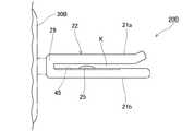
図1に示すように、治療具Xは、前面片1aと後面片1bとを具備し、切開された図2に示す甲状軟骨11の互いに対向する切断端12、12のそれぞれに嵌合させる複数の(本実施形態では一対一組の)挟持部1、1と、複数の挟持部1、1を連結する架橋部2と、を備えている。First, the treatment tool X that is a molding target of the molding jig of the present application will be described.
As shown in FIG. 1, the treatment tool X includes a
前面片1aは、平面視で略短冊状の板状に形成され、端面部1cと表面当接部1dとを備えている。端面部1cは、前面片1aの長手方向の基端側で、折り曲げられて図2に示す甲状軟骨11の切断端面12aに対向させる部分を構成している。表面当接部1dは、前面片1aの端面部1cよりも先端側で、甲状軟骨11の前面11aに配する部分を構成している。
前面片1aには、長手方向に間隔を置いて孔3が複数(本実施形態では2つ)形成されている。これらの孔3、3は、縫合糸(不図示。以下同様)を挿通させることができるようになっており、縫合針を挿通できるよう1.0mm〜2.0mmの大きさに形成されている。The
A plurality of holes 3 (two in this embodiment) are formed in the
図1及び図2に示すように、後面片1bは、前面片1aの端面部1cから図2に示す甲状軟骨11の後面11b側に向かって折れ曲がった部分である。
前面片1aと後面片1bとは一体的に形成されて挟持部1を構成しており、挟持部1は全体として略J字状(逆J字状)に形成されている。As shown in FIGS. 1 and 2, the
The
挟持部1において、前面片1aの長さは、甲状軟骨11を挟持するのに必要十分であって、甲状軟骨11の形態に沿える程度の長さであればよく、具体的には、8mm〜12mm程度に設定されていることが好ましい。また、後面片1bは、甲状軟骨11の切断端12の端縁から甲状軟骨11の下にある軟部組織40の端縁に触れる程度の長さとなっていることが好ましく、具体的には、1.5mm〜3.5mm程度であることが好ましい。 In the sandwiching
図2に示すように、挟持部1は、前面片1aが甲状軟骨11の前面11a側及び切断端面12aに配され、後面片1bが甲状軟骨11の後面11b側に配され、互いに対向する甲状軟骨11の切断端12、12のそれぞれに嵌合し得るように、左右対称に一対設けられている。また、一対の挟持部1、1は、架橋部2によって連結されている。
図1に示すように、架橋部2は、挟持部1を連結する部分であり、端面部1cの延出方向中間部で挟持部1を連結している。架橋部2の長さ(d)、すなわち両挟持部1、1の間隔Dは、図2に示す拡開させた甲状軟骨11の切断端12、12同士の間の距離に相当し、発声障害を持つ患者の症状、患者の体型、発声状態に応じて異なるが、一般に2〜6mmの範囲に設定される。As shown in FIG. 2, in the sandwiching
As shown in FIG. 1, the bridging
挟持部1及び架橋部2は、いずれもチタンで構成されている。
成形治具20Aの使用対象となる治療具Xに用いられるチタン金属は、純金属としてのチタンに限定されず、生体用金属材料として人工骨、人工関節、人工歯根にも利用されているチタン合金を包含する。具体的には、発ガン性やアレルギーの原因が指摘されているNiを含まず、生体適合性に優れたチタン合金として知られているTi−6Al−4Vなどを用いることができる。チタン又はチタン合金は、摩耗や溶出を防止するために、NやCのイオン注入により表面改質されたものを用いてもよい。Both the sandwiching
The titanium metal used in the treatment tool X, which is the target of the
表面当接部1dと後面片1bとの間隔(端面部1cの幅寸法)tは、図2に示す甲状軟骨11の厚さ寸法よりも僅かに大きいことが好ましく、具体的には2〜4mm程度であることが好ましい。間隔tが図2に示す甲状軟骨11の厚さ寸法よりも小さいと、甲状軟骨11を締め付け、挟持部1が甲状軟骨11を長期間圧迫し続けることになり、甲状軟骨11の摩減や損傷を招くおそれがあるからである。一方、表面当接部1dと後面片1bとの間隔tが甲状軟骨11の厚さ寸法と比べて大き過ぎると、実質的に甲状軟骨11を挟持し難く、甲状軟骨11に対して挟持部1が相対的に位置ずれ(スライド)しやすくなるからである。 The distance t between the
次に、成形治具20Aの構成について説明する。
図3又は図4に示すように、成形治具20Aは、前面片1aの基端側の孔3及びその周辺の表面及び裏面の両面からを覆うように前面片1aを挟み込む一対の保持部21a,21bを備えている。これらの互いに対向する一対の保持部21a,21bは、クリップ部22を構成している。Next, the configuration of the
As shown in FIG. 3 or FIG. 4, the
図4に示すように、保持部21a,21bはいずれも金属又は剛性の高い合成樹脂などの材料により矩形の板状に形成されている。図5に示すように、保持部21の側縁Sは、ほぼ直線状に形成されている。これらの保持部21a,21bは、長手方向の一端部においてヒンジ23を介して連結されている。保持部21aはヒンジ23を介して回動する可動側保持部21aとなっており、保持部21bは固定側保持部21bとなっている。
固定側保持部21bと可動側保持部21aとは、治療具Xの前面片1aをその厚さ方向から挟み込んで確実に保持することができる間隔(アローワンス)を設けて重ね合わされるように形成されている。As shown in FIG. 4, each of the holding
The fixed-
図4及び図5に示すように、前面片1aに接する固定側保持部21bの保持面24bには、図1に示す前面片1aの孔3に挿入可能な突起25が形成されている。突起25は、孔3の形状及び大きさに合わせて形成され、孔3に突起25を挿入した状態で水平方向に搖動し難いように設けられている。また固定側保持部21bの先端には、可動側保持部21aを重ねた状態を保持するための係止部26が設けられている。係止部26は、回動して固定側保持部21bに重ねられた可動側保持部21aの先端に留められて、不用意に回動しないようにする留め具となっている。なお、係止部26は必須ではない。 As shown in FIGS. 4 and 5, a
前面片1aに接する可動側保持部21aの保持面24aには、突起25に対応する位置突起25を嵌合させる窪み部27が形成されている。なお、突起25の突出高さが前面片1aの厚さ以下である場合には、窪み部27は無くてもかまわない。 The holding
可動側保持部21a及び固定側保持部21bの幅寸法は、前面片1aの基端側の孔3及びその周辺を覆いつつ孔3,3同士の間に側縁Sが位置し得る限り特に限定されないが、例えば、長手方向の寸法は5mm以上60mm以下、短手方向の寸法が2.5mm以上5mm以下に形成されているのが好ましい。また、可動側保持部21a及び固定側保持部21b同士の間(前面片1aを挿入するためのアローワンス)は、0.1mm以上0.4mm以下に設定されていることが好ましい。 The width dimension of the movable-
次に、成形治具20Aの使用方法と作用、機能及び効果について説明する。
成形治具20Aを使用するには、図4又は図5に示すように、可動側保持部21aを回動させて拡開させておき、前面片1aの長手方向と固定側保持部21bの長手方向とが略直交するように、前面片1aの基端側の孔3を固定側保持部21bの突起25に合わせて前面片1aを固定側保持部21bに配置する。Next, a method of using the
In order to use the
そして、図3に示すように可動側保持部21aを回動させて前面片1aを挟んだ状態で固定側保持部21bに重ね、係止部26で可動側保持部21aを固定側保持部21bに固定する。 Then, as shown in FIG. 3, the movable
そうすると、成形治具20Aに保持された治療具Xの前面片1aの基端側の孔3は成形治具20Aによりカバーされ、保持部21の側縁Sから前面片1aの先端が飛び出した状態となる。 Then, the
この状態で成形治具20Aから突出した前面片1aの先端を保持し折り曲げると、クリップ部22が剛性の高い素材により形成されているため、クリップ部22に覆われた孔3の周辺で前面片1aが折り曲げられることなく、クリップ部22の側縁Sに沿う位置で折り曲げられる。
したがって、孔3を通る線上で前面片1aを折り曲げることにより前面片1aにおいて剛性が低下した箇所で破断が生じることを防止することができるという効果を奏する。If the tip of the
Therefore, by bending the
また、本実施形態では、図2に示すように保持部21の側縁Sを前面片1aの孔3,3の間に設定し、これらの間を折り曲げた場合を例示したが、前面片1aの折り曲げは、架橋部2と架橋部2の直近の孔3との間、すなわち前面片1aの表面当接部1dの基端部と、孔3,3との間の2箇所を折り曲げるようにするのが好ましい。このように前面片1aを表面当接部1dの基端部と孔3,3の間にくる表面当接部1dの中央付近との2箇所で折り曲げると、前面片1aが甲状軟骨11の前面11aに馴染みやすくなるとともに、前面片1aの折り曲げをより緩やかにすることができる。 Further, in the present embodiment, as shown in FIG. 2, the side edge S of the holding
なお、前面片1aの折り曲げ時に、成形治具20Aから突出した前面片1aの先端側を別個の成形治具20Aによって挟み込んで、成形治具20A,20Aを把持して孔3,3の間を折り曲げるようにしてもよい。 When the
次に、図6及び図7を用いて、本発明の第2の実施形態の成形治具20Bについて説明する。
なお、本実施形態においては、第1の実施形態の成形治具20Aと共通する点についてはその説明を省略し、相違する点を中心に説明する。Next, a
In this embodiment, the description of the points common to the
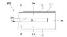
本実施形態の成形治具20Bは、図6に示すように、互いに対向する保持部21aと保持部21bとの間隔が固定され、保持部21a,21bのいずれも基端部29を軸として回動しない構成となっている点で第1の実施形態の成形治具20Aと異なっている。
保持部21a,21bは、治療具Xの前面片1aの厚さ寸法と同等の又は前面片1aの厚さ寸法よりも僅かに小さい間隔Kを空けて、一つの長尺な矩形の板状体が折り曲げられた形状で成形されている。As shown in FIG. 6, the
The holding
突起25が設けられていない保持部21aは、その先端が折れ曲がって前面片1aを挿入しやすいようになっている。
保持部21a及び保持部21bは、基端部29において一体的に形成され固定した形状となっており、それぞれが内側に向かって付勢し得る。
保持部21bには、前面片1aを嵌合させることのできる凹部45が形成されている。The holding
The holding
The holding
この構成により、保持部21a,21b同士の間に治療具Xの前面片1aを挿入した際に、保持部21a,21bは、前面片1aの厚さで押し広げられることなく前面片1aの表面及び裏面の双方に付勢し、前面片1aが突起25に差し掛かってから乗り越えようとしている間更に強く付勢する。そして、保持部21a,21bは、この付勢力によって、前面片1aの孔3が突起25に差し掛かったところで孔3に突起25を嵌合させ、前面片1aの表面及び裏面に再び付勢して前面片1aを保持する。 With this configuration, when the
したがって、成形治具20Bは、前面片1aの折り曲げにおいて成形治具20Aと同様の作用、機能及び効果を奏するだけでなく、保持部21の先端同士を固定するための係止部26を用いることなく前面片1aをしっかりと保持することができるという効果を奏する。
また、成形治具20Bは、保持部21aを回動させるという動作を省いて、保持部21a,21b間に前面片1aを挿入するだけで簡単に前面片1aを保持することができるという効果を奏する。Therefore, the forming
Further, the
また、保持部21bの突起25に前面片1aの孔3を係合させる構成になっているため、前面片1aに対する保持部21a,21bの位置決めが確実となり、一方の孔3が保持部21aに覆われて見えなくても、確実に孔3,3の間において前面片1aを折り曲げることができるという効果を奏する。 Further, since the
なお、第1の実施形態の成形治具20A及び第2の実施形態の20Bのいずれのクリップ部22についても、クリップ部22の基端部29に人の手によるグリップを容易にする操作部30Bが取り付けられていてもよい。この操作部30Bは、クリップ部22の操作が容易になるものであればどのような形状であってもよいが、例えば成形治具20A又は20Bを取り扱う者が掌全体又は掌と指先で把持しやすい棒状に形成されていてもよい。 It should be noted that, with regard to both the
次に、図8−図10を用いて、本発明の第3の実施形態の成形治具20Cについて説明する。
なお、本実施形態の成形治具20Cは、第2の実施形態の成形治具20Bの応用例であるので、第2の実施形態と共通する点についてはその説明を省略し、相違する点を中心に説明する。Next, a
Since the
成形治具20Cは、図8又は図9に示すように、クリップ部22の保持部21aと保持部21bとが一体的に成形されかつ保持部21a及び保持部21b間が固定されている点で第2の実施形態の成形治具20Bと共通する。しかし、成形治具20Cは、主として以下の点で成形治具20Bを異なっている。 In the
すなわち、成形治具20Cの前面片1aの表面側を受ける保持部21b(以下「下側保持部21b」という)は、下側保持部21bの一端部とこの一端部と反対の端部との両方に保持部21a(以下「上側保持部21a」という)が設けられている。なお、下側保持部21bは、前面片1a,1a双方の少なくとも一部を受けることができる大きさで略平板状に形成されている。そして、前面片1aの折り曲げに用いる上側保持部21a及び下側保持部21b以外の部分が成形治具20Cを把持して操作するための操作部30Cとなっている。
以下、成形治具20Cの成形治具20Bとの相違点を具体的に説明する。That is, the holding
Hereinafter, the difference between the
成形治具20Cは、図8に示すように、平面視が略矩形の下側保持部21bと、下側保持部21bの一辺に沿う端部から立ち上がった連結部33と、連結部33の上端から下側保持部21bに対向する方向に延びる上側保持部21a,21aとを備えている。 As shown in FIG. 8, the
下側保持部21bは、前面片1a,1aのそれぞれの少なくとも一部を設置させることができる大きさで、略矩形の平板状に形成されている。具体的には、下側保持部21bは、一対の前面片1a,1aを載置させ、折り曲げたい箇所から前面片1aの先端を突出させた場合に、他方の前面片1aの少なくとも一部が下側保持部21b上に位置する大きさで形成されている。なお、この際、他方の前面片1aの全体が下側保持部21b上に配置されていても、他方の前面片1aの先端が下側保持部21bから突出していても構わない。 The
連結部33は、下側保持部21bの一辺に沿う端部から略直角に立ち上がって側壁を形成し、下側保持部21bと上側保持部21aとの間に一定の隙間を形成している。連結部33の上側保持部21aの先端方向を向く側面34aは、垂直に立ち上がっており、後述する収容部34の一部を形成するとともに、治療具Xの挿入時に治療具Xの端部を受け止められるようになっている。 The connecting
上側保持部21a,21aは、連結部33の一辺に沿う方向(すなわち前面片1a,1aを配する方向)の両端の上端部から下側保持部21bに対向するように板状に突出している。すなわち、上側保持部21a,21a同士は互いに間隔を空けて設けられている。また、上側保持部21a,21aと連結部33とは、平面視略U字状に形成されている。そして、上側保持部21a,21aと連結部33とにより切り欠かれたような形状となった収容部34に、架橋部2を配置させることができるようになっている。 The
また、上側保持部21a,21aの保持面(すなわち下側保持部21bに対向する面)31a,31aは、同一面上に形成され、下側保持部21bとの間で一方向に貫通する溝部Kを形成している。この溝部Kは、治療具Xを挿入させ得るようになっている。
また、前面片1aを突出させる側になる上側保持部21aの側端面S1は、上側保持部21aの幅寸法を保持面31aから上面31bに向けてだんだん小さくする傾斜面になっている。Further, the holding
Further, the side end surface S1 of the upper holding
上側保持部21a,21a間の距離は、前面片1aを溝部Kに挿入して架橋部2を収容部34に配置させ、前面片1aの先端を一方の上側保持部21aから突出させた際に、他方の前面片1aの一部が他方の上側保持部21aに覆われる距離に形成されている。なお、本実施形態では、前面片1aを前記の状態とした際に、もう一方の前面片1aの全体が下側保持部21b上に配され且つ同前面片1aの先端部が上側保持部21aに覆われる構成となっている。 The distance between the
また、一方の上側保持部21aは、他方の上側保持部21aよりも肉厚に形成されている。言い換えると、一方の上側保持部21aは、他方の上側保持部21aと同一面上に保持面31aを形成しているため、一方の上側保持部21aの高さが他方の上側保持部21aの高さよりも高くなっている。連結部33は、これに合わせて、一方の上側保持部21a側から他方の上側保持部21a側に向かって徐々に肉厚になっている。 Further, the one
より薄型に形成された上側保持部21aの延出方向の先端には突起35が形成され、下側保持部21bには突起35に対向するように突起36が形成されている。これらの突起35,36は、下側保持部21bの端面32cと同等の位置から突出している。
突起35,36は、リング状の係止部材37を嵌め込ませる係止部39を構成している。これらの突起35,36及び係止部材37は、前面片1aの折り曲げ時に、上側保持部21aが拡開方向に弾性変形することを防止する手段である。A
The
係止部材37には、突起35,36をちょうど挿入できる開口部38が形成されている。係止部材37は、上側保持部21aと下側保持部21bとの間隔が大きくなるのを防止することができる限り、リング状である必要はなく、突起35,36を挟み込むことができるU字状に形成されていてもよい。 The locking
上側保持部21a,21aの厚さはそれぞれ、1.9mm以上で形成されていればよいが、設置する治療具Xの前面片1aと後面片1bとの間の寸法に合わせて形成されていることがより好ましい。
連結部33の厚さは、3.0mm以上で形成されていればよいが、3.4mm以上16mm以下に形成されていることが好ましい。The
The thickness of the connecting
溝部Kの溝幅は、治療具Xの前面片1aの厚さと同等以上で前面片1aの厚さ+1mm以下に設定されているとよい。
下側保持部21bは、上側保持部21aよりもやや大きい厚さに、具体的には、上側保持部21aよりも1mm以上2mm以下の範囲で大きく形成されている。The groove width of the groove portion K is preferably set to be equal to or more than the thickness of the
The
成形治具20Cは、剛性のある材料で形成されていれば、合成樹脂、ステンレス等の金属等どのような素材により形成されていてもよい。
以上に説明したように形成された成形治具20Cの上側保持部21a,21aは、下側保持部21bの両端に互いに間隔を空けて形成されており、使用する一方の上側保持部21a側以外の部分が、成形治具20Cを把持して操作し易くする操作部30Cを構成している。The
The
次に、成形治具20Cの使用方法及び作用について説明する。
成形治具20Cを使用するにあたっては、図8に示すように、治療具Xの前面片1aを下側保持部21b側に向け、架橋部2が収容部34に収まるように溝部Kに治療具Xを配置させる。Next, a usage method and an operation of the
When using the
前面片1aの孔3,3の間を折り曲げたい場合は、治療具Xの端面部1cを上側保持部21aの側端面S2に寄せて、前面片1aを側端面S1側から孔3が一つ見えるようにクリップ部22から突出させる。上側保持部21aの幅寸法は、前面片1aの孔3,3同士の間に上側保持部21aの側端面S1の下端が位置し得るように設定されている。したがって、前面片1aの基端側の孔3を上側保持部21aが覆った状態で、孔3,3の間より先端が上側保持部21aの側端面S1から突出する。この状態で、上側保持部21aの突起35及び下側保持部21bの突起36に係止部材37を嵌合させて、成形治具20Cに治療具Xを固定する。 When it is desired to bend between the
次に、前面片1aを突出させた方の上側保持部21a以外の部分、すなわち操作部30Cを手で把持するとともに、突出した前面片1aの先端をペンチ等でつかみ、前面片1aをクリップ部22の側端面S1の下端縁に沿って所望の角度に折り曲げる。
なお、折り曲げに際しては、図10に示すように、前面片1aの突出した部分の略全体を更に別個の成形治具20Cのクリップ部22で挟み、成形治具20C,20C間で前面片1aを折り曲げてもよい。Next, while gripping the portion other than the
At the time of bending, as shown in FIG. 10, substantially the entire protruding portion of the
このように前面片1aを折り曲げると、前面片1aの基端部側の孔3の周辺を折り曲げてしまうことなく、孔3と孔3との間の前面片1aの幅寸法が十分な箇所において前面片1aを甲状軟骨の形状に合わせて折り曲げることができる。特に、前面片1aを図10に示すように二つの成形治具20Cを用いて折り曲げた場合、二つの成形治具20Cで前面片1aの孔3,3をそれぞれ覆って折り曲げることができるので、より容易に孔3,3の間を折り曲げることができる。
したがって、前面片1aの幅寸法が小さくなった孔3を通る線上で前面片1aを折り曲げることにより前面片1aが破断することを回避することができるという効果を奏する。When the
Therefore, it is possible to prevent the
また、前面片1aの基端側の孔3よりも基端側において前面片1aを折り曲げたい場合には、前面片1aを側端面S1側から溝Kに挿入し、架橋部2及び他方の前面片1aを側端面S1から突出させる。そして、架橋部2付近を把持して前面片1aの基端部を折り曲げる。
このように成形治具20Cを用いることにより前面片1aの基端部の直近であって孔3を避けた箇所において前面片1aを折り曲げることができる。Further, when it is desired to bend the
By using the
また、成形治具20Cは、治療具Xのほぼ全体を収容させた操作部30Cを持つことができ、折り曲げたい前面片1aの先端だけを突出させる構成である。したがって、成形治具20Cは、前面片1aの折り曲げを容易的かつ安定的にすることができるという効果を奏する。 Further, the
また、成形治具20Cは、突起35,36を係止部材37により固定することができるため、折り曲げ時の上側保持部21a及び下側保持部21bの変形を防止することができるという効果を奏する。
なお、本実施形態で説明した係止部材37は、クリップ部22を挟んで確実に固定するか、クリップ部22が変形し難い程度の剛性を持たせていれば必須ではない。Further, in the
The locking
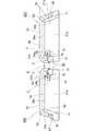
また、成形治具20Cは、ステンレス等の剛性の高い材料により形成した場合には、図11に示すように、薄型でコンパクトに形成することができる。
また、成形治具20Cの左右の上側保持部21a,21aは、図11及び図12に示すように厚さが同一に形成されていてもよい。When the
Further, the left and right upper
また、成形治具20Cの上側保持部21a,21a間は、折り曲げようとする前面片1aを一方の上側保持部21aに設置した際に、異なる前面片1aが他方の上側保持部21aに覆われなくてもよい。
また、側端面S2は、保持面31aに向かって幅方向が広がる傾斜面を有していてもよい。Between the
Further, the side end surface S2 may have an inclined surface whose width direction widens toward the holding
また、成形治具20Cの上側保持部21aは、図11に示すように、長手方向に幅寸法を異ならせていてもよい。上側保持部21aをこのように形成することで、基端部からの孔3の位置もしくは孔3,3間の位置が異なる前面片1aを同じ成形治具20Cで取り扱うことができるという効果を奏する。 The
また、連結部33と上側保持部21aとにより形成される角部の内側(すなわち上側保持部21aと連結部33との交差部の内壁側)70及び上側保持部21aの幅寸法を変える角部70は、円筒状に切り欠かれていてもよい。成形治具20Cの成形において平面同士が完全に所望の角度で交わる角部を形成しようしても、角部の隅のごく僅かな部分に成形治具20Cの肉が残ってしまう。そうすると、治療具Xを受け止める収容部34の側面34aに治療具Xの端部を当てることができず、ぐらつかせてしまう。したがって、角部70を円筒状の切欠き70にすることにより、平面同士が交わる箇所に肉が残った角部とすることを回避して、側面34aに治療具Xをしっかりと当てることができるようになっている。上側保持部21aの幅寸法を変える角部70についても、上側保持部21aの先端方向を向く面34bが治療具Xの一部を受け止める面となるので、同様のことが言える。 Further, the inside of the corner formed by the connecting
また、側端面S2に沿う下側保持部21bの表面には、条状の溝71が形成されていてもよい。このような溝71を形成していることで、治療具Xと下側保持部21bとの摩擦面が少なくなるため、治療具Xに細かな傷等がつくことを防止することができるという効果を奏する。 A strip-shaped
なお、前面片1aの基端側の孔3よりも基端側において前面片1aを折り曲げたい場合には、図11,図12に示すように、成形治具20Cを2つ用いて前面片1aを両側から挟み込み、成形治具20C,20C同士を折り畳む方向に折り曲げてもよい。このような折り曲げ方は、図8に示す成形治具20Cにおいても同様に適用することができる。 In addition, when it is desired to bend the
また、下側保持部21bの裏面には、図13に示すように同心円状に波型の凹凸による滑り止め50が形成されていてもよい。この場合、同心円状の凹凸の滑り止め50は、成形治具21Cを把持した際に概ね指の腹が来る位置に並べて複数形成しているとよい。このように滑り止め50を形成していると、成形治具20Cを把持するのに適した位置を触感で把握することができるという効果を奏する。なお、滑り止め50の形状は、図13に示したものに限定されない。 In addition, as shown in FIG. 13, a
次に、図14−図16を用いて、本発明の第4の実施形態の成形治具20Dについて説明する。
なお、本実施形態の成形治具20Dは、第1の実施形態の成形治具20Aの変形例であるので、第1の実施形態の成形治具20Aと共通する点についてはその説明を省略し、相違する点を中心に説明する。Next, a
Since the
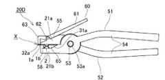
図14に示すように、成形治具20Dは、軸部53において回転自在に固定された一対の挟持半体51,52を備えている。
挟持半体51は、軸部53の挿通部53aの先端側に形成された下側保持部21bと、挿通部53aに対して下側保持部21bの反対側に形成されたレバー54とを備えている。As shown in FIG. 14, the
The sandwiching
挟持半体52は、軸部53の挿通部53aの先端側に形成された上側保持部21aと、挿通部53aに対して上側保持部21aの反対側に形成されたレバー54とを備えている。
挟持半体51,52は、挿通部53aに軸部53を嵌合させ、軸部53を交点として互いにクロスするように組み立てられ、いわゆるペンチのような構成をなしている。The holding
The sandwiching halves 51, 52 are assembled so that the
上側保持部21a及び下側保持部21bは対を成しており、前面片1aを挟んで固定可能な保持面31a,32aを有している。保持面31a,32aは、上側保持部21a及び下側保持部21bの先端部に形成され、共に平坦面を有して互いに密接するようになっている。 The
上側保持部21aは、保持面31aに対して所定の角度をなして基端すなわち軸部53に向かってV字状に拡がる傾斜面(外側面ともいう)55を有している。保持面31a及び傾斜面55がなす角度は、必ずしも限定されないが10度以上30以下に設定されており、好ましくは15度以上25度以下に設定されている。 The
下側保持部21bの保持面32aよりも基端側は切り欠かれて空間65が形成されている。下側保持部21bの外側面58は、略L字状に形成されている。
上側保持部21a及び下側保持部21bの幅寸法(図14における奥行き寸法)は、前面片1aの幅寸法以上となるように設定されている。A
The width dimension (depth dimension in FIG. 14) of the
一方の保持面32aには、前面片1aの孔3に嵌合させる突起56が形成され、他方の保持面31aには突起56を受ける不図示の凹所が形成されている。保持面31a,32aは、突起56に孔3を挿通させた場合に、少なくとも孔3の全体を覆い得るように形成されている。 One
傾斜面55には、上側保持部21aの先端の直近において上側保持部21aの先端から突出した前面片1aを折り曲げる押圧部材60が固定されている。
押圧部材60は、レバー部61と軸部62と押圧部63とを有している。
レバー部61は、直線の棒状に形成されている。A pressing
The pressing
The
押圧部63は、軸部62を起点として傾斜面55から離間する方向に延び、略L字状に折れ曲がっている。押圧部63は、レバー部61の押し上げに連動して上側保持部21aの傾斜面55に近接し、上側保持部21aの先端から突出した前面片1aを押して曲げられるようになっている。 The
以上の構成において、前面片1aの基端側の孔3よりも基端側を折り曲げたい場合、図14に示すように、前面片1aの基端側の孔3に突起56を挿通して上側保持部21a及び下側保持部21bで挟み、その先端から架橋部2を突出させる。この場合、成形治具20Dは、保持面31a,32aによって基端側の孔3を覆い、この孔3から離れた位置に保持面31aの先端縁が位置するように設定される。また、保持面32aに載せた前面片1aの後面片1bの先端が下側保持部21bの外側面58に略接する位置にくるため、治療具Xをセットし易くなっている。
前面片1aを上側保持部21a及び下側保持部21bで挟んだら、レバー61を押し下げ、押圧部63で孔3よりも基端側を押し下げることにより前面片1aを折り曲げる。In the above-mentioned configuration, when it is desired to bend the base end side of the
After sandwiching the
また、前面片1aの孔3,3の間を折り曲げたい場合、前面片1aの先端側の孔3に突起56を挿入し、図14に示すのと同様に、上側保持部21a及び下側保持部21bの先端から架橋部2を突出させることも可能である。この場合でも孔3を確実に覆って、保持面32aの先端縁が孔3,3の間に位置させ、先端縁の直近で折り曲げをすることができる。 Further, when it is desired to bend between the
ただし、前面片1aの先端部だけを上側保持部21a及び下側保持部21bで挟む場合、バランスが悪くなって治療具Xのセットがし難いことがあるので、孔3,3を折り曲げたい場合は、図15に示すようにセットすることが好ましい。 However, when only the tip of the
すなわち、折り曲げたい前面片1aの基端側の孔3に突起56を挿入し、架橋部2及び他方の前面片1aを空間65内に収容させる。そうすると、前面片1aの孔3,3の間に保持面32aの先端縁が位置して、この箇所で折り曲げをすることができるようになる。そして、このように治療具Xをセットすると、後面片1bの先端が下側保持部21bの切り欠かれた内側面に近接し、治療具Xが架橋部2側に大きく傾くのを防止することができるので、治療具Xの設置が容易となる。また、折り曲げる前面片1aと異なる前面片1aの先端が下側保持部21bの内側面に支持されることもあり、治療具Xの設置時の安定性が高められる。 That is, the
以上の構成により、成形治具20Dは、曲げる箇所としたくない孔3及びその周辺を被った状態で簡単かつ確実に前面片1aを保持することができ、かつ押圧部材60によって孔3を通らない箇所で容易に前面片1aを折り曲げることができるという効果を奏する。 With the above configuration, the
また、成形治具20Dの構成によれば、孔3,3間を折り曲げる際に、前面片1aの先端部を上側保持部21a及び下側保持部21bから突出させてそれ以外の部分を保持面31a,32a及び空間65で安定的かつ確実に保持できるようにすることができるという効果を奏する。 Further, according to the configuration of the
なお、成形治具20Dは、図16に示すように、下側保持部21bに空間65を形成する切欠きを形成せず、保持面31a,32aを密接可能な構成としてもよい。
このような構成によっても、成形治具20Dは、上側保持部21aと下側保持部21bとによって前面片1aの孔3を確実に覆って、上側保持部21a及び下側保持部21bの先端から突出した前面片1aを前記先端の直近で折り曲げることができるという効果を奏する。As shown in FIG. 16, the
Even with such a configuration, the
以上、本発明の各実施形態を例示したが本発明は上記実施形態の内容に限定されるものではなく、各実施形態の構成を適宜組み合わせて応用することができる。例えば、第2の実施形態の成形治具20Bに、第3の実施形態で示したような係止部材37を用いてクリップ部22の拡開を防止するといった応用ができる。 Although the respective embodiments of the present invention have been illustrated above, the present invention is not limited to the contents of the above embodiments, and the configurations of the respective embodiments can be appropriately combined and applied. For example, the forming
また、各実施形態では、成形治具20A−20Cを一つだけ用い、クリップ部22から突出させた前面片1aの先端部はペンチ等の他の治具を用いる方法を説明したが、クリップ部22から突出させた前面片1aの先端部を更に他の成形治具20A−20Cのいずれかのクリップ部22で保持させ、前面片1aを折り曲げるようにしてもよい。このようにクリップ部22から突出させた先端部も成形治具20A−20Cのいずれかで保持することによって、折り曲げが一層容易になるとともに、先端部に形成された孔3を通る線上で前面片1aを折り曲げることを防止することができるという効果を奏する。 Further, in each of the embodiments, a method has been described in which only one
1 挟持部
1a 前面片
1b 後面片
2 架橋部
3 孔
11 甲状軟骨
20A−20D 成形治具
21 保持部
21 上側保持部
22 クリップ部
25,56 突起
24a,24b,31a,32a,32b 保持面
30B,30C 操作部
33 連結部(側壁)
34 収容部
39 係止部
45 凹部
53 軸部
54 レバー(操作部)
60 押圧部材
70 円筒状の切欠き
71 溝
S 端縁
S1 傾斜面
X 発声障害治療具
DESCRIPTION OF
34
60
Claims (15)
Translated fromJapanese前記前面片をその表面及び裏面の両面から挟み込んで前記孔の少なくとも一部を覆う一対の保持部を備えたクリップ部を有している発声障害治療具の成形治具。A front piece placed on the anterior surface of the incised thyroid cartilage and a back surface piece placed on the posterior surface of the thyroid cartilage; A molding jig that includes a sandwiching portion and a bridge portion that connects the plurality of sandwiching portions to each other, and is a molding jig that deforms the vocal dysfunction treatment device having a hole formed in the front piece.
A molding jig for a vocal dysfunction treatment tool, comprising a clip part having a pair of holding parts for sandwiching the front piece from both the front surface and the back surface and covering at least a part of the hole.
前記前面片を覆う保持部と前記側壁との交差部の内壁が略円筒状に切り欠かれている請求項1から4のいずれか一項に記載の発声障害治療具の成形治具。Of the pair of holding parts, a side wall extending in an L shape intersecting with the holding part is formed at an end of the holding part covering the front piece.
The molding jig for a vocal dysfunction treatment tool according to any one of claims 1 to 4, wherein an inner wall of an intersection of the holding portion that covers the front surface piece and the side wall is cut out in a substantially cylindrical shape.
前記前面片の前記孔に重ならない位置に直線状の折り曲げ線を仮設定し、
前記前面片の一部の表面及び裏面を覆って前記前面片を挟み込む一対の保持部を備えたクリップ部に前記前面片の一部を挟み込み、前記前面片の残りの部分を突出させ、
前記保持部の側縁の一方を前記折り曲げ線に沿わせ、
前記前面片の前記残りの部分をつまみ、前記側縁を中心に前記前面片を折り曲げる発声障害治療具の前面片を折り曲げる方法。
A flat plate-shaped front piece disposed on the front surface of the incised thyroid cartilage and a rear surface piece disposed on the rear surface of the thyroid cartilage; A method of bending a front piece of a dysphonia treatment device comprising a plurality of holding portions and a bridging portion connecting the plurality of holding portions to each other, wherein a hole is formed in the front piece.
Temporarily setting a linear bending line at a position that does not overlap with the hole of the front piece,
Part of the front piece is sandwiched in a clip portion that includes a pair of holding portions that covers a part of the front surface and the back surface of the front piece, and the remaining portion of the front piece is projected.
One of the side edges of the holding portion along the bending line,
A method of bending the front piece of the dysphonia treatment device, comprising pinching the remaining portion of the front piece and bending the front piece around the side edge.
Applications Claiming Priority (3)
| Application Number | Priority Date | Filing Date | Title |
|---|---|---|---|
| JP2017117033 | 2017-06-14 | ||
| JP2017117033 | 2017-06-14 | ||
| PCT/JP2018/022611WO2018230613A1 (en) | 2017-06-14 | 2018-06-13 | Tool for molding dysphonia treatment tool, and method for bending front piece of dysphonia treatment tool |
Publications (1)
| Publication Number | Publication Date |
|---|---|
| JPWO2018230613A1true JPWO2018230613A1 (en) | 2020-04-16 |
Family
ID=64659283
Family Applications (1)
| Application Number | Title | Priority Date | Filing Date |
|---|---|---|---|
| JP2019525489APendingJPWO2018230613A1 (en) | 2017-06-14 | 2018-06-13 | Molding jig for dysphonia treatment device and method for bending front piece of dysphonia treatment device |
Country Status (5)
| Country | Link |
|---|---|
| US (1) | US11517424B2 (en) |
| EP (1) | EP3639771A4 (en) |
| JP (1) | JPWO2018230613A1 (en) |
| CN (1) | CN110831524B (en) |
| WO (1) | WO2018230613A1 (en) |
Families Citing this family (1)
| Publication number | Priority date | Publication date | Assignee | Title |
|---|---|---|---|---|
| US11523908B2 (en)* | 2016-12-29 | 2022-12-13 | Nobelpharma Co., Ltd. | Dysphonia treatment tool |
Citations (4)
| Publication number | Priority date | Publication date | Assignee | Title |
|---|---|---|---|---|
| WO1998029058A1 (en)* | 1996-12-31 | 1998-07-09 | M.P.R.S. Ltd. | A modular implant for pelvis reconstruction |
| JP2003102743A (en)* | 2001-07-26 | 2003-04-08 | Gunze Ltd | Processing method and tool for bone joining plate |
| WO2017026493A2 (en)* | 2015-08-10 | 2017-02-16 | ノーベルファーマ株式会社 | Voice disorder treatment tool and voice disorder treatment set |
| JP2017118920A (en)* | 2015-12-28 | 2017-07-06 | ノーベルファーマ株式会社 | Molding tool for voice disturbance treatment instrument |
Family Cites Families (15)
| Publication number | Priority date | Publication date | Assignee | Title |
|---|---|---|---|---|
| JP4153372B2 (en) | 2003-06-11 | 2008-09-24 | 信彦 一色 | Voice disorder treatment device |
| US8074655B2 (en)* | 2004-02-26 | 2011-12-13 | Linguaflex, Inc. | Methods and devices for treating sleep apnea and snoring |
| DE102004055671B4 (en)* | 2004-08-11 | 2010-01-07 | Erbe Elektromedizin Gmbh | Electrosurgical instrument |
| JP5167030B2 (en)* | 2008-08-26 | 2013-03-21 | タキロン株式会社 | Osteosynthesis plate processing instrument |
| US9237924B2 (en)* | 2011-06-14 | 2016-01-19 | Aerin Medical, Inc. | Methods and devices to treat nasal airways |
| CN104105891B (en)* | 2012-02-10 | 2016-10-12 | 百乐仕株式会社 | Fixture and there is the component mounting structure of this fixture |
| JP5875419B2 (en)* | 2012-03-15 | 2016-03-02 | テルモ株式会社 | Medical tool set |
| WO2013172940A1 (en)* | 2012-05-14 | 2013-11-21 | DePuy Synthes Products, LLC | Cutting/bending tool for polymer implant |
| CN104958108B (en)* | 2013-03-15 | 2018-04-20 | 阿普力特医疗股份有限公司 | Method and apparatus for treating Glottic insufficiency |
| CN203235790U (en)* | 2013-05-08 | 2013-10-16 | 深圳市银宝山新科技股份有限公司 | Bending clamp with adjustable fixed length for deformation of wire rod or board |
| JP2015080803A (en)* | 2013-10-23 | 2015-04-27 | オリンパス株式会社 | Flexure processing method and device |
| JP6434921B2 (en)* | 2014-01-27 | 2018-12-05 | 学校法人東邦大学 | Voice disorder treatment device |
| WO2015164619A1 (en)* | 2014-04-23 | 2015-10-29 | The General Hospital Corporation | Tongue retractors for frenotomies |
| WO2016002924A1 (en)* | 2014-07-04 | 2016-01-07 | 国立大学法人 熊本大学 | Titanium spacer used for type ii thyroplasty and kit for same |
| TWM541287U (en)* | 2016-06-24 | 2017-05-11 | 阿普力特醫療股份有限公司 | An implant system for treating glottic insufficiency |
- 2018
- 2018-06-13JPJP2019525489Apatent/JPWO2018230613A1/enactivePending
- 2018-06-13CNCN201880041459.2Apatent/CN110831524B/ennot_activeExpired - Fee Related
- 2018-06-13USUS16/622,710patent/US11517424B2/enactiveActive
- 2018-06-13EPEP18818553.2Apatent/EP3639771A4/ennot_activeWithdrawn
- 2018-06-13WOPCT/JP2018/022611patent/WO2018230613A1/ennot_activeCeased
Patent Citations (4)
| Publication number | Priority date | Publication date | Assignee | Title |
|---|---|---|---|---|
| WO1998029058A1 (en)* | 1996-12-31 | 1998-07-09 | M.P.R.S. Ltd. | A modular implant for pelvis reconstruction |
| JP2003102743A (en)* | 2001-07-26 | 2003-04-08 | Gunze Ltd | Processing method and tool for bone joining plate |
| WO2017026493A2 (en)* | 2015-08-10 | 2017-02-16 | ノーベルファーマ株式会社 | Voice disorder treatment tool and voice disorder treatment set |
| JP2017118920A (en)* | 2015-12-28 | 2017-07-06 | ノーベルファーマ株式会社 | Molding tool for voice disturbance treatment instrument |
Non-Patent Citations (1)
| Title |
|---|
| 讃岐徹治・一色信彦: "痙攣性発声障害手術例の検討−甲状軟骨形成術2型の手術手技を中心に−", 耳鼻と臨床, vol. 51巻,5号, JPN6008008424, 2005, JP, pages 381 - 386, ISSN: 0004834085* |
Also Published As
| Publication number | Publication date |
|---|---|
| CN110831524A (en) | 2020-02-21 |
| EP3639771A1 (en) | 2020-04-22 |
| WO2018230613A1 (en) | 2018-12-20 |
| US20200330219A1 (en) | 2020-10-22 |
| EP3639771A4 (en) | 2021-03-17 |
| CN110831524B (en) | 2023-05-16 |
| US11517424B2 (en) | 2022-12-06 |
Similar Documents
| Publication | Publication Date | Title |
|---|---|---|
| US11937820B2 (en) | Jaw for clip applier | |
| CN104994793B (en) | Disposable capsulorhexis forceps | |
| US5011487A (en) | Vascular clamp assembly | |
| JPWO2018235402A1 (en) | Clip treatment tool | |
| KR20150085835A (en) | Locking member for a bone fixation device | |
| US20200297347A1 (en) | Clip retention for surgical clip applier | |
| EP3335648B1 (en) | Voice disorder treatment tool | |
| JPWO2018230613A1 (en) | Molding jig for dysphonia treatment device and method for bending front piece of dysphonia treatment device | |
| WO2012144950A1 (en) | Surgical forceps | |
| US8147512B1 (en) | Dual closing guide for a surgical instrument | |
| WO2019146806A1 (en) | Ear treatment instrument | |
| JP7468725B2 (en) | forceps | |
| US6863679B1 (en) | Paired forceps | |
| JP5401088B2 (en) | clip | |
| US20190328531A1 (en) | Dysphonia treatment tool | |
| EP3750493A1 (en) | Thyroid cartilage-shape measurement jig | |
| JP2017118920A (en) | Molding tool for voice disturbance treatment instrument | |
| CN115916067A (en) | Surgical Instruments | |
| WO2022102361A1 (en) | Rod pusher and surgical instrument system | |
| JP2019188103A (en) | Nail cover | |
| JP6688855B2 (en) | Medical stainless steel tweezers | |
| KR102097288B1 (en) | orthodontic ligature instrument | |
| WO2025193800A1 (en) | Cutting needle holder | |
| JP5996495B2 (en) | Tweezers for precision work including medical use | |
| JP2021122297A (en) | Auxiliary equipment |
Legal Events
| Date | Code | Title | Description |
|---|---|---|---|
| A621 | Written request for application examination | Free format text:JAPANESE INTERMEDIATE CODE: A621 Effective date:20210608 | |
| RD02 | Notification of acceptance of power of attorney | Free format text:JAPANESE INTERMEDIATE CODE: A7422 Effective date:20211116 | |
| A131 | Notification of reasons for refusal | Free format text:JAPANESE INTERMEDIATE CODE: A131 Effective date:20220726 | |
| A601 | Written request for extension of time | Free format text:JAPANESE INTERMEDIATE CODE: A601 Effective date:20220920 | |
| A521 | Request for written amendment filed | Free format text:JAPANESE INTERMEDIATE CODE: A523 Effective date:20221124 | |
| A02 | Decision of refusal | Free format text:JAPANESE INTERMEDIATE CODE: A02 Effective date:20230328 |