Movatterモバイル変換


[0]ホーム

URL:


JPWO2018220745A1 - Monitoring device - Google Patents

Monitoring device
Download PDF

Info

Publication number
JPWO2018220745A1
JPWO2018220745A1JP2019521598AJP2019521598AJPWO2018220745A1JP WO2018220745 A1JPWO2018220745 A1JP WO2018220745A1JP 2019521598 AJP2019521598 AJP 2019521598AJP 2019521598 AJP2019521598 AJP 2019521598AJP WO2018220745 A1JPWO2018220745 A1JP WO2018220745A1
Authority
JP
Japan
Prior art keywords
target
processing unit
observation
sensor
image
Prior art date
Legal status (The legal status is an assumption and is not a legal conclusion. Google has not performed a legal analysis and makes no representation as to the accuracy of the status listed.)
Granted
Application number
JP2019521598A
Other languages
Japanese (ja)
Other versions
JP6687296B2 (en
Inventor
佑樹 高林
康 小幡
寛夫 松村
Current Assignee (The listed assignees may be inaccurate. Google has not performed a legal analysis and makes no representation or warranty as to the accuracy of the list.)
Mitsubishi Electric Corp
Original Assignee
Mitsubishi Electric Corp
Priority date (The priority date is an assumption and is not a legal conclusion. Google has not performed a legal analysis and makes no representation as to the accuracy of the date listed.)
Filing date
Publication date
Application filed by Mitsubishi Electric CorpfiledCriticalMitsubishi Electric Corp
Publication of JPWO2018220745A1publicationCriticalpatent/JPWO2018220745A1/en
Application grantedgrantedCritical
Publication of JP6687296B2publicationCriticalpatent/JP6687296B2/en
Activelegal-statusCriticalCurrent
Anticipated expirationlegal-statusCritical

Links

Images

Classifications

Landscapes

Abstract

Translated fromJapanese

観測センサ(3)から出力された識別情報によって目標物の大きさを特定し、特定した目標物の大きさ及び観測センサ(3)から出力された目標物観測位置のそれぞれを画像センサ(1)の投影面に変換し、変換した目標物の大きさと、変換した目標物観測位置とから、画像センサ(1)の投影面上で、観測センサ(3)により観測された目標物を包含している範囲である目標物包含観測領域を特定する変換処理部(5)を設け、第1の判定処理部(6)が、変換処理部(5)により特定された目標物包含観測領域と、目標検出部(2)により特定された目標物包含画像領域とを比較して、観測センサ(3)により観測された目標物と、目標検出部(2)により検出された目標物とが同一物であるか否かを判定する。The size of the target is specified based on the identification information output from the observation sensor (3), and each of the specified target size and the target observation position output from the observation sensor (3) is determined by the image sensor (1). Including the target observed by the observation sensor (3) on the projection plane of the image sensor (1) from the converted target size and the converted target observation position. A conversion processing unit (5) for specifying a target inclusion observing region that is a certain range, and the first determination processing unit (6) includes a target inclusion observing region specified by the conversion processing unit (5), a target Comparing the target inclusion image area specified by the detection unit (2), the target observed by the observation sensor (3) and the target detected by the target detection unit (2) are the same. It is determined whether or not there is.

Description

Translated fromJapanese

この発明は、観測センサにより観測された目標物と、画像センサの撮像画像内の目標物とが同一物であるか否かを判定する監視装置に関するものである。  The present invention relates to a monitoring device that determines whether or not a target observed by an observation sensor and a target in a captured image of an image sensor are the same.

例えば、観測諸元が異なるレーダ又はカメラなどの複数のセンサを用いて、航空機、船舶又は車両などの目標物を観測し、複数のセンサにより観測された目標物の同一性を判定する監視装置がある。
この監視装置は、例えば、画像センサから出力された撮像画像内の目標物と、或るレーダにより観測された目標物とが同一物であると判定すれば、或るレーダにより観測された目標物の識別情報を撮像画像上に重ねて表示する。
For example, a monitoring device that observes a target such as an aircraft, a ship, or a vehicle using a plurality of sensors such as radars or cameras having different observation specifications and determines the identity of the target observed by the plurality of sensors. is there.
For example, if it is determined that the target in the captured image output from the image sensor and the target observed by a certain radar are the same, the monitoring apparatus detects the target observed by the certain radar. The identification information is superimposed on the captured image and displayed.

この監視装置を適用可能なシステムとして、例えば、目標物である航空機を観測する航空管制支援システムがある。
航空管制支援システムに適用される監視装置が備えるセンサとして、例えば、空港面探知レーダ(ASDE:Airport Surface Detection Equipment)、空港監視レーダ(ASR:Airport Surveillance Radar)がある。ASDEは目標物である航空機の距離や方位を探知することによって2次元位置を取得することができる。ASRは、例えば、一次監視レーダ(PSR:Primary Surveillance Radar)と、二次監視レーダ(SSR:Secondary Surveillance Radar)とを組み合わせたレーダである。PSRは、目標物である航空機の距離及び方位を探知する。SSRは、レーダのアンテナから送信された電波である質問信号に対して、航空機に搭載されたトランスポンダが応答することによって、目標物の航空機である距離及び方位を探知し、応答信号には、航空機の識別情報及び高度が含まれるため、距離及び方位に加えて、高度を知ることができる。
これらのセンサは、航空機の高度を取得できない場合、2次元位置として取得することになり、航空機の高度が取得できる場合、3次元位置として取得することができる。
また、監視装置が備えるセンサとして、マルチラテレーション(MLAT:MultirateLATion)、広域マルチラテレーション(WAM:Wide Area Multiratelation)、ADS-B(Automatic Dependent Surveillance-Broadcast)out/inなどがある。
これらのセンサは、目標物である航空機の3次元位置及び航空機の識別情報を取得することができる。
As a system to which this monitoring apparatus can be applied, for example, there is an air traffic control support system for observing an aircraft as a target.
As sensors provided in a monitoring device applied to an air traffic control support system, for example, there are an airport surface detection radar (ASDE) and an airport surveillance radar (ASR: Aircraft Radar Radar). ASDE can acquire a two-dimensional position by detecting the distance and direction of the target aircraft. The ASR is, for example, a radar that combines a primary surveillance radar (PSR) and a secondary surveillance radar (SSR). The PSR detects the distance and direction of the target aircraft. The SSR detects the distance and azimuth of the target aircraft as a result of the transponder mounted on the aircraft responding to the interrogation signal transmitted from the radar antenna. In addition to the distance and direction, the altitude can be known.
These sensors are acquired as a two-dimensional position when the altitude of the aircraft cannot be acquired, and can be acquired as a three-dimensional position when the altitude of the aircraft can be acquired.
Also, sensors included in the monitoring device include multilateration (MLAT), wide area multilateration (WAM), ADS-B (Automatic Dependent Survey-Broadcast) out / in, and the like.
These sensors can acquire the three-dimensional position of the target aircraft and the identification information of the aircraft.

以下の特許文献1に開示されている監視装置は、観測センサとして、空港面探知レーダを使用して、空港面を移動する全ての目標物を観測し、全ての目標物の位置及び識別情報を取得するようにしている。目標物には、空港面を移動する航空機のほか、空港面を移動する車両なども含まれる。
また、この監視装置は、画像センサであるビデオカメラを用いて、目標物を撮影し、目標物が映っている撮像画像を取得するようにしている。
この監視装置は、撮像画像内の目標物を検出して、撮像画像上での目標物の位置と、空港面探知レーダにより取得された目標物の位置との相関の有無を判定することで、空港面探知レーダにより観測された目標物と、画像センサの撮像画像内の目標物とが同一物であるか否かを判定している。
The monitoring device disclosed in the followingPatent Document 1 uses an airport surface detection radar as an observation sensor, observes all targets moving on the airport surface, and obtains the positions and identification information of all targets. Try to get. The target includes not only an aircraft moving on the airport surface but also a vehicle moving on the airport surface.
In addition, this monitoring apparatus uses a video camera, which is an image sensor, to capture a target and acquire a captured image showing the target.
This monitoring device detects a target in a captured image and determines whether or not there is a correlation between the position of the target on the captured image and the position of the target acquired by the airport surface detection radar. It is determined whether or not the target observed by the airport surface detection radar is the same as the target in the captured image of the image sensor.

特開平11−160424号公報JP-A-11-160424

従来の監視装置は以上のように構成されているので、目標物が空港面を移動している航空機又は車両などであれば、目標物の同一性を判定することができる。しかし、目標物が飛行中の航空機である場合、撮像画像内の目標物の位置座標を解析しても、目標物の3次元位置を正確に求めることが困難であり、撮像画像上での目標物の3次元位置と、空港面探知レーダにより取得された目標物の3次元位置との相関の有無を判定することができない。このため、目標物が飛行中の航空機である場合、空港面探知レーダにより観測された目標物と、画像センサの撮像画像内の目標物とが同一物であるか否かを判定することができないという課題があった。  Since the conventional monitoring apparatus is configured as described above, the identity of the target can be determined if the target is an aircraft or a vehicle moving on the airport surface. However, when the target is an aircraft in flight, it is difficult to accurately obtain the three-dimensional position of the target even if the position coordinates of the target in the captured image are analyzed. Whether or not there is a correlation between the three-dimensional position of the object and the three-dimensional position of the target acquired by the airport surface detection radar cannot be determined. For this reason, when the target is an aircraft in flight, it cannot be determined whether the target observed by the airport surface detection radar and the target in the image captured by the image sensor are the same. There was a problem.

この発明は上記のような課題を解決するためになされたもので、目標物が飛行中の航空機である場合でも、観測センサにより観測された目標物と、画像センサの撮像画像内の目標物とが同一物であるか否かを判定することができる監視装置を得ることを目的とする。  The present invention has been made to solve the above-described problems. Even when the target is an aircraft in flight, the target observed by the observation sensor, the target in the captured image of the image sensor, and the target It is an object to obtain a monitoring device that can determine whether or not the two are the same.

この発明に係る監視装置は、目標物が存在している領域を撮像して、その領域の撮像画像を出力する画像センサと、画像センサから出力された撮像画像内の目標物を検出し、検出した目標物を包含している範囲である目標物包含画像領域を特定する目標検出部と、目標物を観測して、観測した目標物の識別情報及び観測した目標物の位置である目標物観測位置を出力する観測センサと、観測センサから出力された識別情報によって目標物の大きさを特定し、特定した目標物の大きさ及び観測センサから出力された目標物観測位置のそれぞれを画像センサの投影面に変換し、変換した目標物の大きさと、変換した目標物観測位置とから、画像センサの投影面上で、観測センサにより観測された目標物を包含している範囲である目標物包含観測領域を特定する変換処理部とを設け、第1の判定処理部が、変換処理部により特定された目標物包含観測領域と、目標検出部により特定された目標物包含画像領域とを比較して、観測センサにより観測された目標物と、目標検出部により検出された目標物とが同一物であるか否かを判定するようにしたものである。  The monitoring apparatus according to the present invention images an area in which a target is present, outputs an image captured in the area, detects a target in the captured image output from the image sensor, and detects the target A target detection unit that identifies a target inclusion image area that is a range that includes the target, and observation of the target, identification information of the observed target, and target observation that is the position of the observed target The size of the target is specified by the observation sensor that outputs the position and the identification information output from the observation sensor, and each of the specified target size and the target observation position output from the observation sensor is determined by the image sensor. The target is included in the range including the target observed by the observation sensor on the projection plane of the image sensor from the converted target size and the converted target observation position. Observation area And a first determination processing unit comparing the target object inclusion observation area specified by the conversion processing part with the target object inclusion image area specified by the target detection part, It is determined whether or not the target observed by the observation sensor and the target detected by the target detector are the same.

この発明によれば、観測センサから出力された識別情報によって目標物の大きさを特定し、特定した目標物の大きさ及び観測センサから出力された目標物観測位置のそれぞれを画像センサの投影面に変換し、変換した目標物の大きさと、変換した目標物観測位置とから、画像センサの投影面上で、観測センサにより観測された目標物を包含している範囲である目標物包含観測領域を特定する変換処理部を設け、第1の判定処理部が、変換処理部により特定された目標物包含観測領域と、目標検出部により特定された目標物包含画像領域とを比較して、観測センサにより観測された目標物と、目標検出部により検出された目標物とが同一物であるか否かを判定するように構成したので、目標物が飛行中の航空機である場合でも、観測センサにより観測された目標物と、画像センサの撮像画像内の目標物とが同一物であるか否かを判定することができる効果がある。  According to this invention, the size of the target is specified by the identification information output from the observation sensor, and each of the specified target size and the target observation position output from the observation sensor is displayed on the projection plane of the image sensor. The target inclusion observation area, which is a range including the target observed by the observation sensor on the projection plane of the image sensor from the converted target size and the converted target observation position. And a first determination processing unit compares the target inclusion observation region specified by the conversion processing unit with the target inclusion image region specified by the target detection unit, and performs observation. Since it is configured to determine whether or not the target observed by the sensor and the target detected by the target detector are the same, the observation sensor even if the target is an aircraft in flight By And observed target, and the target in the captured image of the image sensor is effective which can be determined whether one and the same.

この発明の実施の形態1による監視装置を示す構成図である。It is a block diagram which shows the monitoring apparatus by Embodiment 1 of this invention.この発明の実施の形態1による監視装置を示すハードウェア構成図である。It is a hardware block diagram which shows the monitoring apparatus by Embodiment 1 of this invention.監視装置の画像センサ1、観測センサ3及びディスプレイ16を除く構成要素がソフトウェア又はファームウェアなどで実現される場合のコンピュータのハードウェア構成図である。It is a hardware block diagram of a computer in case the components except theimage sensor 1, theobservation sensor 3, and thedisplay 16 of a monitoring apparatus are implement | achieved by software or firmware.監視装置の画像センサ1、観測センサ3及びディスプレイ16を除く構成要素がソフトウェア又はファームウェアなどで実現される場合の処理手順を示すフローチャートである。It is a flowchart which shows the process sequence in case the components except theimage sensor 1, theobservation sensor 3, and thedisplay 16 of a monitoring apparatus are implement | achieved by software or firmware.変換処理部5により画像センサ1の投影面に変換された目標物観測位置及び変換処理部5により特定された目標物包含観測領域を示す説明図である。5 is an explanatory diagram showing a target observation position converted to a projection plane of theimage sensor 1 by aconversion processing unit 5 and a target inclusion observing region specified by theconversion processing unit 5. FIG.図6Aは、目標物の全長と全幅に対応する第1の矩形領域を示す説明図、図6Bは、目標物の全幅と高さに対応する第2の矩形領域を示す説明図である。FIG. 6A is an explanatory diagram illustrating a first rectangular area corresponding to the entire length and the entire width of the target, and FIG. 6B is an explanatory diagram illustrating a second rectangular area corresponding to the entire width and the height of the target.目標物包含観測領域と目標物包含画像領域との重なり範囲Ovを示す説明図である。It is explanatory drawing which shows the overlap range Ov of a target object inclusion observation area | region and a target object inclusion image area | region.目標物包含観測領域と第1及び第2の目標物包含画像領域との重なり範囲Ovを示す説明図である。It is explanatory drawing which shows the overlap range Ov of a target object inclusion observation area | region and the 1st and 2nd target object inclusion image area | region.この発明の実施の形態1による他の監視装置を示す構成図である。It is a block diagram which shows the other monitoring apparatus by Embodiment 1 of this invention.包含領域特定部8により特定される双方包含領域を示す説明図である。It is explanatory drawing which shows the both inclusion area specified by the inclusion area specific |specification part 8. FIG.この発明の実施の形態1による他の監視装置を示す構成図である。It is a block diagram which shows the other monitoring apparatus by Embodiment 1 of this invention.重み付け平均した位置を示す説明図である。It is explanatory drawing which shows the position which carried out the weighted average.観測センサ3に起因する目標物観測位置と目標物画像位置との位置ずれを示す説明図である。It is explanatory drawing which shows the position shift of the target object observation position resulting from theobservation sensor 3, and a target object image position.目標物観測位置の観測誤差範囲及び画像センサ1の投影面上での観測誤差範囲を示す説明図である。It is explanatory drawing which shows the observation error range of a target object observation position, and the observation error range on the projection surface of the image sensor.楕円体の固有ベクトルと長軸の幅との関係を示す説明図である。It is explanatory drawing which shows the relationship between the eigenvector of an ellipsoid, and the width | variety of a major axis.補正前後の目標物包含観測領域及び投影面上での観測誤差範囲を示す説明図である。It is explanatory drawing which shows the observation error range on the target inclusion inclusion observation area | region and projection surface before and behind correction | amendment.この発明の実施の形態3による監視装置を示す構成図である。It is a block diagram which shows the monitoring apparatus by Embodiment 3 of this invention.この発明の実施の形態3による監視装置を示すハードウェア構成図である。It is a hardware block diagram which shows the monitoring apparatus by Embodiment 3 of this invention.この発明の実施の形態4による監視装置を示す構成図である。It is a block diagram which shows the monitoring apparatus by Embodiment 4 of this invention.この発明の実施の形態4による監視装置を示すハードウェア構成図である。It is a hardware block diagram which shows the monitoring apparatus by Embodiment 4 of this invention.観測位置射影部61により算出される射影位置を示す説明図である。It is explanatory drawing which shows the projection position calculated by the observationposition projection part 61. FIG.観測位置射影部61により算出される射影位置と、目標検出部32bから出力される目標物地図座標位置との関係を示す説明図である。It is explanatory drawing which shows the relationship between the projection position calculated by the observationposition projection part 61, and the target object map coordinate position output from the target detection part 32b.第2の判定処理部62の処理内容を示すフローチャートである。7 is a flowchart showing processing contents of a seconddetermination processing unit 62.この発明の実施の形態5による監視装置を示す構成図である。It is a block diagram which shows the monitoring apparatus by Embodiment 5 of this invention.この発明の実施の形態5による監視装置を示すハードウェア構成図である。It is a hardware block diagram which shows the monitoring apparatus by Embodiment 5 of this invention.画像センサ1−1〜1−Nの基準位置と、画像センサ1−1〜1−Nの角度とを示す説明図である。It is explanatory drawing which shows the reference position of image sensor 1-1 to 1-N, and the angle of image sensor 1-1 to 1-N.この発明の実施の形態6による監視装置を示す構成図である。It is a block diagram which shows the monitoring apparatus byEmbodiment 6 of this invention.

以下、この発明をより詳細に説明するために、この発明を実施するための形態について、添付の図面に従って説明する。  Hereinafter, in order to explain the present invention in more detail, modes for carrying out the present invention will be described with reference to the accompanying drawings.

実施の形態1.
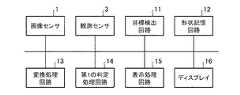
図1は、この発明の実施の形態1による監視装置を示す構成図である。図2は、この発明の実施の形態1による監視装置を示すハードウェア構成図である。
図1及び図2において、画像センサ1は、例えば、光学カメラ又は赤外カメラなどで実現される。
画像センサ1は、目標物が存在している領域として、例えば、移動体が交通する空港敷地内及び空港周辺の領域を撮像して、前記領域の撮像画像を目標検出部2及び表示処理部7に出力する。この目標物には、航空機のほか、地上を走行する車両なども含まれる。さらに、海が近い空港であれば船舶なども含まれ、また、鉄道があれば、鉄道車両なども含まれる。
Embodiment 1 FIG.
1 is a block diagram showing a monitoring apparatus according toEmbodiment 1 of the present invention. FIG. 2 is a hardware configuration diagram showing the monitoring apparatus according toEmbodiment 1 of the present invention.
1 and 2, theimage sensor 1 is realized by, for example, an optical camera or an infrared camera.
Theimage sensor 1 captures, for example, an area in and around an airport site where a moving object is traveling as an area where the target is present, and the captured image of the area is captured by thetarget detection unit 2 and thedisplay processing unit 7. Output to. This target includes not only an aircraft but also a vehicle traveling on the ground. Furthermore, if the airport is near the sea, ships are included, and if there is a railway, railway vehicles are also included.

目標検出部2は、例えば、図2に示す目標検出回路11で実現される。
目標検出部2は、画像センサ1から出力された撮像画像内の目標物を検出する処理を実施する。
目標検出部2は、撮像画像上での検出した目標物の位置である目標物画像位置及び撮像画像上で目標物を包含している範囲である目標物包含画像領域のそれぞれを第1の判定処理部6及び表示処理部7に出力する処理を実施する。
Thetarget detection unit 2 is realized by, for example, atarget detection circuit 11 shown in FIG.
Thetarget detection unit 2 performs a process of detecting a target in the captured image output from theimage sensor 1.
Thetarget detection unit 2 performs a first determination on each of the target image position that is the position of the detected target on the captured image and the target-included image area that is a range that includes the target on the captured image. The process which outputs to theprocess part 6 and thedisplay process part 7 is implemented.

観測センサ3は、画像センサ1以外のセンサであり、例えば、ASR、ASDE、MLAT、WAM、ADS−Bout/inなどで実現される。
観測センサ3は、目標物を観測して、観測した目標物の識別情報及び目標物の3次元位置である目標物観測位置のそれぞれを変換処理部5に出力する。目標物の識別情報には、例えば、航空機の便名のほか、航空機の機体など、目標物の固有の識別番号が含まれている。
物体形状情報格納部4は、例えば、図2に示す形状記憶回路12で実現される。
物体形状情報格納部4は、各種の目標物の形状を示す形状情報を格納している。例えば、目標物の識別情報に対応する形状情報として、識別情報が示す目標物の全長、全幅及び高さなどを格納している。
Theobservation sensor 3 is a sensor other than theimage sensor 1 and is realized by, for example, ASR, ASDE, MLAT, WAM, ADS-Bout / in, or the like.
Theobservation sensor 3 observes the target, and outputs the identification information of the observed target and the target observation position, which is the three-dimensional position of the target, to theconversion processing unit 5. The identification information of the target includes, for example, an identification number unique to the target such as the aircraft flight number as well as the aircraft body.
The object shape information storage unit 4 is realized by, for example, theshape memory circuit 12 shown in FIG.
The object shape information storage unit 4 stores shape information indicating the shapes of various target objects. For example, as the shape information corresponding to the identification information of the target, the total length, full width, height, and the like of the target indicated by the identification information are stored.

変換処理部5は、例えば、図2に示す変換処理回路13で実現される。
変換処理部5は、物体形状情報格納部4から、観測センサ3から出力された識別情報に対応する形状情報を読み出し、形状情報を参照することで、観測センサ3により観測された目標物の大きさを特定する処理を実施する。
変換処理部5は、特定した目標物の大きさ及び観測センサ3から出力された目標物観測位置のそれぞれを画像センサ1の投影面に変換する処理を実施する。
変換処理部5は、変換した目標物の大きさと、変換した目標物観測位置とから、画像センサ1の投影面上で、観測センサ3により観測された目標物を包含している範囲である目標物包含観測領域を特定する処理を実施する。
この実施の形態1では、変換処理部5が、観測センサ3から出力された識別情報に対応する形状情報を参照することで、観測センサ3により観測された目標物の大きさを特定し、特定した目標物の大きさを画像センサ1の投影面に変換する例を示しているが、これに限るものではない。
例えば、観測センサ3が目標物の識別情報を得ることが困難であるような場合、変換処理部5が、予め設定されている目標物の大きさを画像センサ1の投影面に変換するようにしてもよい。
予め設定されている目標物の大きさは、例えば、カタログ上の大きさなどが考えられる。
Theconversion processing unit 5 is realized by, for example, theconversion processing circuit 13 illustrated in FIG.
Theconversion processing unit 5 reads the shape information corresponding to the identification information output from theobservation sensor 3 from the object shape information storage unit 4 and refers to the shape information, whereby the size of the target observed by theobservation sensor 3 is read. A process for specifying the length is performed.
Theconversion processing unit 5 performs a process of converting each of the identified target size and the target observation position output from theobservation sensor 3 into the projection plane of theimage sensor 1.
Theconversion processing unit 5 includes a target that is a range including the target observed by theobservation sensor 3 on the projection plane of theimage sensor 1 from the converted target size and the converted target observation position. A process for specifying the object inclusion observation region is performed.
In the first embodiment, theconversion processing unit 5 specifies the size of the target observed by theobservation sensor 3 by referring to the shape information corresponding to the identification information output from theobservation sensor 3, and specifies Although the example which converts the magnitude | size of the target made into the projection surface of theimage sensor 1 is shown, it does not restrict to this.
For example, when it is difficult for theobservation sensor 3 to obtain the target identification information, theconversion processing unit 5 converts the preset size of the target into the projection plane of theimage sensor 1. May be.
As the size of the target set in advance, for example, the size on a catalog can be considered.

第1の判定処理部6は、例えば、図2に示す第1の判定処理回路14で実現される。
第1の判定処理部6は、変換処理部5により特定された目標物包含観測領域と、目標検出部2から出力された目標物包含画像領域とを比較して、観測センサ3により観測された目標物と、目標検出部2により検出された目標物とが同一物であるか否かを判定する処理を実施する。
即ち、第1の判定処理部6は、画像センサ1の投影面上で、変換処理部5により特定された目標物包含観測領域と、目標検出部2から出力された目標物包含画像領域との重なり範囲を算出する処理を実施する。
また、第1の判定処理部6は、重なり範囲が閾値以上であれば、観測センサ3により観測された目標物と、目標検出部2により検出された目標物とが同一物であると判定し、重なり範囲が閾値未満であれば、観測センサ3により観測された目標物と、目標検出部2により検出された目標物とが同一物でないと判定する処理を実施する。
The firstdetermination processing unit 6 is realized by, for example, the firstdetermination processing circuit 14 illustrated in FIG.
The firstdetermination processing unit 6 compares the target inclusion observation region specified by theconversion processing unit 5 with the target inclusion image region output from thetarget detection unit 2, and is observed by theobservation sensor 3. A process of determining whether or not the target and the target detected by thetarget detection unit 2 are the same is performed.
That is, the firstdetermination processing unit 6 includes the target object inclusion observation region specified by theconversion processing unit 5 and the target object inclusion image region output from thetarget detection unit 2 on the projection plane of theimage sensor 1. A process for calculating the overlapping range is performed.
The firstdetermination processing unit 6 determines that the target observed by theobservation sensor 3 and the target detected by thetarget detection unit 2 are the same if the overlapping range is equal to or greater than the threshold. If the overlapping range is less than the threshold value, a process of determining that the target observed by theobservation sensor 3 and the target detected by thetarget detection unit 2 are not the same is performed.

表示処理部7は、例えば、図2に示す表示処理回路15で実現される。
表示処理部7は、画像センサ1から出力された撮像画像をディスプレイ16に表示する処理を実施する。
表示処理部7は、第1の判定処理部6により同一物であると判定された場合、変換処理部5により画像センサ1の投影面に変換された目標物観測位置及び観測センサ3から出力された識別情報のそれぞれを撮像画像上に表示し、また、目標検出部2から出力された目標物包含画像領域を撮像画像上に表示する処理を実施する。
また、第1の判定処理部6により同一物であると判定されなかった場合でも、表示処理部7は、変換処理部5により画像センサ1の投影面に変換された目標物観測位置、観測センサ3から出力された識別情報、変換処理部5により特定された目標物包含観測領域、目標検出部2から出力された目標物画像位置、目標検出部2から出力された目標物包含画像領域のそれぞれを独立に撮像画像上に表示しても良いこととする。
ディスプレイ16は、例えば、液晶ディスプレイなどの表示装置である。
Thedisplay processing unit 7 is realized by, for example, thedisplay processing circuit 15 illustrated in FIG.
Thedisplay processing unit 7 performs processing for displaying the captured image output from theimage sensor 1 on thedisplay 16.
When it is determined by the firstdetermination processing unit 6 that thedisplay processing unit 7 is the same, thedisplay processing unit 7 is output from the target observation position and theobservation sensor 3 converted to the projection plane of theimage sensor 1 by theconversion processing unit 5. Each identification information displayed is displayed on the captured image, and the target inclusion image area output from thetarget detection unit 2 is displayed on the captured image.
Even if the firstdetermination processing unit 6 does not determine that the objects are the same, thedisplay processing unit 7 converts the target observation position and the observation sensor converted into the projection plane of theimage sensor 1 by theconversion processing unit 5. 3, the identification information output from 3, the target inclusion observation region specified by theconversion processing unit 5, the target image position output from thetarget detection unit 2, and the target inclusion image region output from thetarget detection unit 2. May be displayed on the captured image independently.
Thedisplay 16 is a display device such as a liquid crystal display, for example.

図1では、監視装置の構成要素である画像センサ1、目標検出部2、観測センサ3、物体形状情報格納部4、変換処理部5、第1の判定処理部6、表示処理部7及びディスプレイ16のそれぞれが、図2に示すような専用のハードウェアで実現されるものを想定している。即ち、画像センサ1、目標検出回路11、観測センサ3、形状記憶回路12、変換処理回路13、第1の判定処理回路14、表示処理回路15及びディスプレイ16で実現されるものを想定している。  In FIG. 1, animage sensor 1, atarget detection unit 2, anobservation sensor 3, an object shape information storage unit 4, aconversion processing unit 5, a firstdetermination processing unit 6, adisplay processing unit 7 and a display, which are components of the monitoring device. Each of 16 is assumed to be realized by dedicated hardware as shown in FIG. That is, what is realized by theimage sensor 1, thetarget detection circuit 11, theobservation sensor 3, theshape memory circuit 12, theconversion processing circuit 13, the firstdetermination processing circuit 14, thedisplay processing circuit 15, and thedisplay 16 is assumed. .

ここで、形状記憶回路12は、例えば、RAM(Random Access Memory)、ROM(Read Only Memory)、フラッシュメモリ、EPROM(Erasable Programmable Read Only Memory)、EEPROM(Electrically Erasable Programmable Read Only Memory)などの不揮発性又は揮発性の半導体メモリや、磁気ディスク、フレキシブルディスク、光ディスク、コンパクトディスク、ミニディスク、DVD(Digital Versatile Disc)などが該当する。
また、目標検出回路11、変換処理回路13、第1の判定処理回路14及び表示処理回路15は、例えば、単一回路、複合回路、プログラム化したプロセッサ、並列プログラム化したプロセッサ、ASIC(Application Specific Integrated Circuit)、FPGA(Field−Programmable Gate Array)、または、これらを組み合わせたものが該当する。
Here, theshape memory circuit 12 includes, for example, a RAM (Random Access Memory), a ROM (Read Only Memory), a flash memory, an EPROM (Erasable Programmable Read Only Memory), an EEPROM (Electrically Erasable Memory), and the like. Alternatively, a volatile semiconductor memory, a magnetic disk, a flexible disk, an optical disk, a compact disk, a mini disk, a DVD (Digital Versatile Disc), or the like is applicable.
Thetarget detection circuit 11, theconversion processing circuit 13, the firstdetermination processing circuit 14, and thedisplay processing circuit 15 are, for example, a single circuit, a composite circuit, a programmed processor, a parallel programmed processor, an ASIC (Application Specific). An integrated circuit (FPGA), a field-programmable gate array (FPGA), or a combination thereof is applicable.

監視装置の画像センサ1、観測センサ3及びディスプレイ16を除く構成要素は、専用のハードウェアで実現されるものに限るものではなく、ソフトウェア、ファームウェア、または、ソフトウェアとファームウェアとの組み合わせで実現されるものであってもよい。
ソフトウェア又はファームウェアはプログラムとして、コンピュータのメモリに格納される。コンピュータは、プログラムを実行するハードウェアを意味し、例えば、CPU(Central Processing Unit)、中央処理装置、処理装置、演算装置、マイクロプロセッサ、マイクロコンピュータ、プロセッサ、DSP(Digital Signal Processor)、GPU(Graphics Processing Unit)などが該当する。
The components other than theimage sensor 1, theobservation sensor 3, and thedisplay 16 of the monitoring device are not limited to those realized by dedicated hardware, but are realized by software, firmware, or a combination of software and firmware. It may be a thing.
Software or firmware is stored as a program in the memory of a computer. The computer means hardware for executing a program. For example, a central processing unit (CPU), a central processing unit, a processing unit, a processing unit, a microprocessor, a microcomputer, a processor, a DSP (Digital Signal Processor), a GPU (Graphics) (Processing Unit).

図3は、監視装置の画像センサ1、観測センサ3及びディスプレイ16を除く構成要素がソフトウェア又はファームウェアなどで実現される場合のコンピュータのハードウェア構成図である。
監視装置の画像センサ1、観測センサ3及びディスプレイ16を除く構成要素がソフトウェア又はファームウェアなどで実現される場合、物体形状情報格納部4をコンピュータのメモリ21上に構成するとともに、目標検出部2、物体形状情報格納部4、変換処理部5、第1の判定処理部6及び表示処理部7の処理手順をコンピュータに実行させるためのプログラムをメモリ21に格納し、コンピュータのプロセッサ22がメモリ21に格納されているプログラムを実行するようにすればよい。
FIG. 3 is a hardware configuration diagram of a computer when components other than theimage sensor 1, theobservation sensor 3, and thedisplay 16 of the monitoring device are realized by software or firmware.
When components other than theimage sensor 1, theobservation sensor 3, and thedisplay 16 of the monitoring device are realized by software or firmware, the object shape information storage unit 4 is configured on thememory 21 of the computer, and thetarget detection unit 2, A program for causing the computer to execute processing procedures of the object shape information storage unit 4, theconversion processing unit 5, the firstdetermination processing unit 6, and thedisplay processing unit 7 is stored in thememory 21, and theprocessor 22 of the computer stores in thememory 21. The stored program may be executed.

図4は、監視装置の画像センサ1、観測センサ3及びディスプレイ16を除く構成要素がソフトウェア又はファームウェアなどで実現される場合の処理手順を示すフローチャートである。
また、図2では、監視装置の構成要素のそれぞれが専用のハードウェアで実現される例を示し、図3では、監視装置の画像センサ1、観測センサ3及びディスプレイ16を除く構成要素がソフトウェアやファームウェアなどで実現される例を示しているが、監視装置における一部の構成要素が専用のハードウェアで実現され、残りの構成要素がソフトウェアやファームウェアなどで実現されるものであってもよい。
FIG. 4 is a flowchart showing a processing procedure when components other than theimage sensor 1, theobservation sensor 3, and thedisplay 16 of the monitoring apparatus are realized by software or firmware.
2 shows an example in which each component of the monitoring device is realized by dedicated hardware. In FIG. 3, the components other than theimage sensor 1, theobservation sensor 3, and thedisplay 16 of the monitoring device are software and Although an example realized by firmware or the like is shown, some components in the monitoring apparatus may be realized by dedicated hardware, and the remaining components may be realized by software or firmware.

次に動作について説明する。
画像センサ1は、目標物が存在している領域として、例えば、移動体が交通する空港敷地内及び空港周辺の領域を撮像して、前記領域の撮像画像を目標検出部2及び表示処理部7に出力する。この目標物には、航空機のほか、地上を走行する車両なども含まれる。
Next, the operation will be described.
Theimage sensor 1 captures, for example, an area in and around an airport site where a moving object is traveling as an area where the target is present, and the captured image of the area is captured by thetarget detection unit 2 and thedisplay processing unit 7. Output to. This target includes not only an aircraft but also a vehicle traveling on the ground.

目標検出部2は、画像センサ1から出力された撮像画像内の目標物を検出する処理を実施する(図4のステップST1)。
撮像画像内の目標物を検出する処理自体は、公知の技術であるため詳細な説明を省略する。
目標検出部2は、検出した目標物の撮像画像上での位置である目標物画像位置を第1の判定処理部6及び表示処理部7に出力する。
また、目標検出部2は、撮像画像上で目標物を包含している範囲である目標物包含画像領域と、検出した目標物を識別するID(IDentification)とを第1の判定処理部6及び表示処理部7に出力する。このIDは、目標検出部2により任意に割り当てられた番号等である。
ここで、目標物包含画像領域は、例えば、撮像画像上で目標物を囲む矩形の枠、曲線と直線から構成する枠が該当する。
また、目標物画像位置は、例えば、目標物包含画像領域の中心に存在している画素の位置座標が該当する。
Thetarget detection unit 2 performs a process of detecting a target in the captured image output from the image sensor 1 (step ST1 in FIG. 4).
Since the process itself for detecting the target in the captured image is a known technique, detailed description thereof is omitted.
Thetarget detection unit 2 outputs a target image position that is a position of the detected target on the captured image to the firstdetermination processing unit 6 and thedisplay processing unit 7.
In addition, thetarget detection unit 2 uses a firstdetermination processing unit 6 and an ID (IDentification) that identifies a target inclusion image area that is a range including the target on the captured image, and an ID (IDentification) that identifies the detected target. Output to thedisplay processing unit 7. This ID is a number or the like arbitrarily assigned by thetarget detection unit 2.
Here, the target object including image region corresponds to, for example, a rectangular frame surrounding the target object on the captured image, or a frame formed of a curve and a straight line.
In addition, the target image position corresponds to, for example, the position coordinates of a pixel existing at the center of the target-including image area.

この実施の形態1では、監視装置が1つの画像センサ1を実装している例を想定しているが、監視装置が複数の画像センサ1を実装しているものであってもよい。
監視装置が複数の画像センサ1を実装している場合、目標検出部2が、画像センサ1毎に、独立して目標物を検出するようにしてもよいし、複数の画像センサ1により撮影された画像をパノラマ映像として1つの撮像画像に合成し、合成した撮像画像上で目標物を検出するようにしてもよい。また、複数の画像センサ1が、独立して目標物を検出すると同時に、他の画像センサ1と協調動作することで、複数の画像センサ1間を跨がって存在する同一の目標物について同一のIDを付与し、前記IDが同じ目標物については、ある画像センサ1で検出した目標物を他の画像センサ1で検出しない、もしくは後段の処理部へ出力しないようにしてもよい。
In the first embodiment, an example in which the monitoring device is mounted with oneimage sensor 1 is assumed, but the monitoring device may be mounted with a plurality ofimage sensors 1.
When the monitoring apparatus has a plurality ofimage sensors 1 mounted, thetarget detection unit 2 may detect the target independently for eachimage sensor 1 or may be photographed by the plurality ofimage sensors 1. The captured images may be combined into one captured image as a panoramic image, and the target may be detected on the combined captured image. In addition, the plurality ofimage sensors 1 independently detect the target and simultaneously operate in cooperation with theother image sensors 1, so that the same target exists across the plurality ofimage sensors 1. For a target having the same ID, a target detected by acertain image sensor 1 may not be detected by anotherimage sensor 1 or may not be output to a subsequent processing unit.

観測センサ3は、目標物を観測して、観測した目標物の識別情報及び目標物の3次元位置である目標物観測位置(X1,Y1,Z1)のそれぞれを変換処理部5及び表示処理部7に出力する。また、前述した通り、単一の観測センサ3を扱う際に、センサによってはASRのように距離と方位、ASDEのように地上面の2次元位置のみ取得される場合がある。ASRの場合は、航空機の気圧高度、もしくは気圧高度に標準大気の補正を加えて海面からの高度に変換し、距離、方位、高度を3次元位置(X1,Y1,Z1)へ変換して出力しても良いこととする。ASDEの場合は、目標物の高度として、デフォルト値(航空管制のルール上、現実的にあり得る値)を設定して、3次元位置(X1,Y1,Z1)を出力しても良いこととする。
目標物の識別情報には、例えば、航空機の便名又は航空機の機体の情報など、目標物の固有の識別番号が含まれている。
また、観測センサ3は、目標物の推定速度を示す速度ベクトルを取得できる場合は変換処理部5に出力しても良いこととする。
Theobservation sensor 3 observes the target and converts the observed target identification information and the target observation position (X1, Y1, Z1), which is the three-dimensional position of the target, into theconversion processing unit 5 and the display processing unit, respectively. 7 is output. Further, as described above, when thesingle observation sensor 3 is handled, only the two-dimensional position on the ground surface such as the distance and the azimuth and ASDE may be acquired depending on the sensor. In the case of ASR, the atmospheric pressure altitude of the aircraft or the altitude altitude is corrected to the altitude from the sea level by correcting the standard atmosphere, and the distance, azimuth, and altitude are converted to the three-dimensional position (X1, Y1, Z1) and output You may do it. In the case of ASDE, it is possible to set a default value (a value that is realistically possible according to air traffic control rules) as the altitude of the target and output a three-dimensional position (X1, Y1, Z1). To do.
The identification information of the target includes, for example, a unique identification number of the target such as an aircraft flight number or aircraft fuselage information.
In addition, theobservation sensor 3 may output to theconversion processing unit 5 when a speed vector indicating the estimated speed of the target can be acquired.

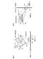
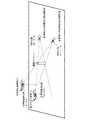
変換処理部5は、図5に示すように、観測センサ3から出力された目標物観測位置(X1,Y1,Z1)を画像センサ1の投影面に投影することで、目標物観測位置(X1,Y1,Z1)を画像センサ1の投影面の座標(u,v)に変換する(図4のステップST2)。
図5は、変換処理部5により画像センサ1の投影面に変換された目標物観測位置及び変換処理部5により特定された目標物包含観測領域を示す説明図である。
画像センサ1の投影面の座標(u,v)は、目標物包含観測領域における中心画素の座標に相当する。
As shown in FIG. 5, theconversion processing unit 5 projects the target observation position (X1, Y1, Z1) output from theobservation sensor 3 onto the projection plane of theimage sensor 1, so that the target observation position (X1 , Y1, Z1) are converted into the coordinates (u, v) of the projection plane of the image sensor 1 (step ST2 in FIG. 4).
FIG. 5 is an explanatory diagram showing the target observation position converted into the projection plane of theimage sensor 1 by theconversion processing unit 5 and the target inclusion observation region specified by theconversion processing unit 5.
The coordinates (u, v) of the projection plane of theimage sensor 1 correspond to the coordinates of the central pixel in the target inclusion observation region.

例えば、変換処理部5は、以下の式(1)を用いることで、目標物観測位置(X1,Y1,Z1)を画像センサ1の投影面の座標(u,v)に変換することができる。

Figure 2018220745
式(1)において、Aは、画像センサ1の内部パラメータ、Rは、回転行列、Tは、平行移動ベクトルである。
world,Yworld,Zworldは、目標物が存在している3次元直交座標系の各軸の座標値である。例えば、観測センサ3が設置されている位置を原点とする北基準直交座標系が考えられる。
image,vimageは、画像センサ1の投影面上での各軸の座標値である。
したがって、目標物観測位置(X1,Y1,Z1)を式(1)の座標値(Xworld,Yworld,Zworld)に代入すると、式(1)の画像センサ1の投影面上での座標値(uimage,vimage)が、画像センサ1の投影面の座標(u,v)となる。For example, theconversion processing unit 5 can convert the target observation position (X1, Y1, Z1) into the coordinates (u, v) of the projection plane of theimage sensor 1 by using the following formula (1). .
Figure 2018220745
In Expression (1), A is an internal parameter of theimage sensor 1, R is a rotation matrix, and T is a translation vector.
Xworld , Yworld , and Zworld are coordinate values of each axis of the three-dimensional orthogonal coordinate system where the target is present. For example, a north reference orthogonal coordinate system whose origin is the position where theobservation sensor 3 is installed can be considered.
uimage and vimage are the coordinate values of each axis on the projection plane of theimage sensor 1.
Therefore, if the target observation position (X1, Y1, Z1) is substituted into the coordinate values (Xworld , Yworld , Zworld ) of the equation (1), the coordinates on the projection plane of theimage sensor 1 of the equation (1) The values (uimage , vimage ) are the coordinates (u, v) of the projection plane of theimage sensor 1.

変換処理部5は、観測センサ3から目標物の識別情報を受けると、物体形状情報格納部4から識別情報に対応する形状情報の読み出しを行う。
変換処理部5は、形状情報を参照することで、目標物の全長、全幅及び高さを把握する。目標物の識別情報が入力されない場合は、例えば、一般的な全長、全幅及び高さをデフォルト値予め設定しておき、使用しても良いこととする。
また、変換処理部5は、観測センサ3から速度ベクトルを受けると、速度ベクトルから目標物の進行方向を把握する。速度ベクトルが入力されない場合は、例えば、航空管制のルール上、予め設定されているコース又は一般的な速度よって、速度ベクトルのデフォルト値を設定して、目標物の進行方向を把握しても良いこととする。
図6は、変換処理部5により特定される目標物包含観測領域を示す説明図である。
図6Aは、目標物の全長と全幅に対応する第1の矩形領域を示し、図6Bは、目標物の全幅と高さに対応する第2の矩形領域を示している。
Upon receiving the target identification information from theobservation sensor 3, theconversion processing unit 5 reads shape information corresponding to the identification information from the object shape information storage unit 4.
Theconversion process part 5 grasps | ascertains the full length, full width, and height of a target object with reference to shape information. When the identification information of the target is not input, for example, general total length, full width, and height may be preset and used as default values.
Further, when theconversion processing unit 5 receives the velocity vector from theobservation sensor 3, theconversion processing unit 5 grasps the traveling direction of the target from the velocity vector. If the speed vector is not input, for example, the default value of the speed vector may be set according to a preset course or general speed according to the rules of air traffic control, and the traveling direction of the target may be grasped. I will do it.
FIG. 6 is an explanatory diagram showing the target inclusion observation area specified by theconversion processing unit 5.
6A shows a first rectangular area corresponding to the overall length and width of the target, and FIG. 6B shows a second rectangular area corresponding to the overall width and height of the target.

変換処理部5は、図6Aに示すように、目標物の進行方向に対応する辺の長さが目標物の全長であり、進行方向と直交する方向に対応する辺の長さが目標物の全幅である第1の矩形領域を生成する。
また、変換処理部5は、図6Bに示すように、高さ方向に対応する辺の長さが目標物の高さであり、水平方向に対応する辺の長さが目標物の全幅である第2の矩形領域を生成する。
ここで、目標物の進行方向が把握できない場合でも、予め設定しておいた進行方向や目標物の傾きよって、矩形領域を生成しても良いこととする。一方、目標物のピッチ、ヨー、ロールなどの詳細な情報が得られる場合は利用しても良いこととする。
As shown in FIG. 6A, theconversion processing unit 5 has the length of the side corresponding to the traveling direction of the target as the total length of the target, and the length of the side corresponding to the direction orthogonal to the traveling direction as the target. A first rectangular area having a full width is generated.
In addition, as shown in FIG. 6B, theconversion processing unit 5 has the side length corresponding to the height direction as the height of the target, and the side length corresponding to the horizontal direction as the full width of the target. A second rectangular area is generated.
Here, even when the traveling direction of the target cannot be grasped, a rectangular region may be generated based on the previously set traveling direction and the inclination of the target. On the other hand, when detailed information such as the pitch, yaw and roll of the target can be obtained, it may be used.

次に、変換処理部5は、図6Aに示すように、第1の矩形領域における2つの対角線D1,D2のうち、画像センサ1の視線方向との角度が直角に近い方向の対角線D1を選択する。
変換処理部5は、選択した対角線D1の端点a1,a2を画像センサ1の投影面に投影することで、対角線D1の端点a1,a2を画像センサ1の投影面の座標a3,a4に変換する。
Next, as illustrated in FIG. 6A, theconversion processing unit 5 selects a diagonal line D1 having an angle close to a right angle with respect to the line-of-sight direction of theimage sensor 1 out of the two diagonal lines D1 and D2 in the first rectangular area. To do.
Theconversion processing unit 5 projects the end points a1 and a2 of the selected diagonal line D1 onto the projection plane of theimage sensor 1, thereby converting the end points a1 and a2 of the diagonal line D1 into the coordinates a3 and a4 of the projection plane of theimage sensor 1. .

対角線D1の端点a1,a2を画像センサ1の投影面の座標a3,a4に変換するには、対角線D1の端点a1,a2における3次元直交座標系の座標を得る必要がある。
観測センサ3から出力された目標物観測位置(X1,Y1,Z1)が、第1の矩形領域の中心位置に対応していれば、目標物観測位置(X1,Y1,Z1)と第1の矩形領域の大きさとから、対角線D1の端点a1,a2における3次元直交座標系の座標を得ることができる。
しかし、一般的には、観測センサ3から出力された目標物観測位置(X1,Y1,Z1)は、第1の矩形領域の中心位置に対応しているとは限らない。
目標物観測位置(X1,Y1,Z1)が、第1の矩形領域の中心位置に対応していない場合、対角線D1の端点a1,a2における3次元直交座標系の座標を得ることが困難である。
そこで、この実施の形態1では、例えば、以下のようにして、対角線D1の端点a1,a2を画像センサ1の投影面の座標a3,a4に変換する。
In order to convert the end points a1 and a2 of the diagonal line D1 into the coordinates a3 and a4 of the projection surface of theimage sensor 1, it is necessary to obtain the coordinates of the three-dimensional orthogonal coordinate system at the end points a1 and a2 of the diagonal line D1.
If the target observation position (X1, Y1, Z1) output from theobservation sensor 3 corresponds to the center position of the first rectangular area, the target observation position (X1, Y1, Z1) and the first target observation position (X1, Y1, Z1) From the size of the rectangular area, the coordinates of the three-dimensional orthogonal coordinate system at the end points a1 and a2 of the diagonal line D1 can be obtained.
However, generally, the target observation position (X1, Y1, Z1) output from theobservation sensor 3 does not necessarily correspond to the center position of the first rectangular area.
When the target observation position (X1, Y1, Z1) does not correspond to the center position of the first rectangular area, it is difficult to obtain the coordinates of the three-dimensional orthogonal coordinate system at the end points a1, a2 of the diagonal line D1. .
Therefore, in the first embodiment, for example, the end points a1 and a2 of the diagonal line D1 are converted to the coordinates a3 and a4 on the projection surface of theimage sensor 1 as follows.

対角線D1の端点a1,a2は、第1の矩形領域に9おける対角線D1の端点であるため、端点a1と端点a2との距離を算出することができる。このため、例えば、端点a2における3次元直交座標系の座標を、端点a1における3次元直交座標系の座標で表すことができる。
端点a1の未知の座標を式(1)に代入することで、端点a1の座標を画像センサ1の投影面の座標a3に変換し、端点a1の座標で表した端点a2の座標を式(1)に代入することで、端点a2の座標を画像センサ1の投影面の座標a4に変換すれば、座標a3と座標a4との距離L1−2を求めることができる。
画像センサ1の投影面上での目標物観測位置である座標(u,v)は既に算出しているため、座標(u,v)と距離L1−2から、画像センサ1の投影面の座標a3,a4を算出することができる。
Since the end points a1 and a2 of the diagonal line D1 are the end points of the diagonal line D1 in the firstrectangular area 9, the distance between the end point a1 and the end point a2 can be calculated. For this reason, for example, the coordinates of the three-dimensional orthogonal coordinate system at the end point a2 can be represented by the coordinates of the three-dimensional orthogonal coordinate system at the end point a1.
By substituting the unknown coordinates of the end point a1 into the equation (1), the coordinates of the end point a1 are converted into the coordinates a3 of the projection surface of theimage sensor 1, and the coordinates of the end point a2 expressed by the coordinates of the end point a1 are expressed by the equation (1). ), The distance L1-2 between the coordinates a3 and the coordinates a4 can be obtained by converting the coordinates of the end point a2 into the coordinates a4 of the projection surface of theimage sensor 1.
Since the coordinates (u, v) that are the target observation positions on the projection plane of theimage sensor 1 have already been calculated, the coordinates of the projection plane of theimage sensor 1 are calculated from the coordinates (u, v) and the distance L1-2. a3 and a4 can be calculated.

また、変換処理部5は、図6Bに示すように、第2の矩形領域における2つの対角線D3,D4のうち、画像センサ1の視線方向との角度が直角に近い方向の対角線D3を選択する。
変換処理部5は、選択した対角線D3の端点b1,b2を画像センサ1の投影面に投影することで、対角線D3の端点b1,b2を画像センサ1の投影面の座標b3,b4に変換する。
対角線D3の端点b1,b2を画像センサ1の投影面の座標b3,b4に変換する処理も、対角線D1の端点b1,b2を画像センサ1の投影面の座標b3,b4に変換する処理と同様に行うことができる。
Further, as illustrated in FIG. 6B, theconversion processing unit 5 selects a diagonal line D3 having an angle close to a right angle with the line-of-sight direction of theimage sensor 1 out of the two diagonal lines D3 and D4 in the second rectangular area. .
Theconversion processing unit 5 projects the end points b1 and b2 of the selected diagonal line D3 onto the projection surface of theimage sensor 1, thereby converting the end points b1 and b2 of the diagonal line D3 into the coordinates b3 and b4 of the projection surface of theimage sensor 1. .
The process of converting the end points b1 and b2 of the diagonal line D3 into the coordinates b3 and b4 of the projection plane of theimage sensor 1 is the same as the process of converting the end points b1 and b2 of the diagonal line D1 into the coordinates b3 and b4 of the projection plane of theimage sensor 1. Can be done.

変換処理部5は、変換した投影面の座標a3,a4及び座標b3,b4から、図5に示すように、画像センサ1の投影面上で、目標物を包含している範囲である目標物包含観測領域を特定する(図4のステップST3)。
図5において、目標物包含観測領域の左上の端点の座標は、(a3,b3)であり、目標物包含観測領域の左下の端点の座標は、(a3,b4)である。
また、目標物包含観測領域の右上の端点の座標は、(a4,b3)であり、目標物包含観測領域の右下の端点の座標は、(a4,b4)である。
As shown in FIG. 5, theconversion processing unit 5 converts the target object that is in the range including the target object from the converted coordinates a3 and a4 and the coordinates b3 and b4 on the projection surface of theimage sensor 1. An inclusive observation region is specified (step ST3 in FIG. 4).
In FIG. 5, the coordinates of the upper left end point of the target object including observation area are (a3, b3), and the coordinates of the lower left end point of the target object including observation area are (a3, b4).
Also, the coordinates of the upper right end point of the target inclusion observation area are (a4, b3), and the coordinates of the lower right end point of the target inclusion observation area are (a4, b4).

第1の判定処理部6は、変換処理部5により特定された目標物包含観測領域と、目標検出部2から出力された目標物包含画像領域とを比較して、観測センサ3により観測された目標物と、目標検出部2により検出された目標物とが同一物であるか否かを判定する。
即ち、第1の判定処理部6は、図7に示すように、画像センサ1の投影面上で、変換処理部5により特定された目標物包含観測領域と、目標検出部2から出力された目標物包含画像領域との重なり範囲Ovを算出する(図4のステップST4)。
図7は、目標物包含観測領域と目標物包含画像領域との重なり範囲Ovを示す説明図である。
The firstdetermination processing unit 6 compares the target inclusion observation region specified by theconversion processing unit 5 with the target inclusion image region output from thetarget detection unit 2, and is observed by theobservation sensor 3. It is determined whether or not the target and the target detected by thetarget detection unit 2 are the same.
That is, as shown in FIG. 7, the firstdetermination processing unit 6 outputs the target inclusion observation area specified by theconversion processing unit 5 and thetarget detection unit 2 on the projection plane of theimage sensor 1. The overlapping range Ov with the target object including image area is calculated (step ST4 in FIG. 4).
FIG. 7 is an explanatory diagram showing an overlapping range Ov between the target object inclusion observation area and the target object inclusion image area.

第1の判定処理部6は、図7に示すように、算出した重なり範囲Ovと事前に設定された閾値Thとを比較する(図4のステップST5)。
第1の判定処理部6は、重なり範囲Ovが閾値Th以上であれば(図4のステップST5:YESの場合)、観測センサ3により観測された目標物と、目標検出部2により検出された目標物とが同一物であると判定する(図4のステップST6)。
第1の判定処理部6は、重なり範囲Ovが閾値Th未満であれば(図4のステップST5:NOの場合)、観測センサ3により観測された目標物と、目標検出部2により検出された目標物とが同一物でないと判定する(図4のステップST7)。
As shown in FIG. 7, the firstdetermination processing unit 6 compares the calculated overlap range Ov with a preset threshold value Th (step ST5 in FIG. 4).
The firstdetermination processing unit 6 detects the target observed by theobservation sensor 3 and thetarget detection unit 2 if the overlapping range Ov is equal to or greater than the threshold Th (in the case of step ST5: YES in FIG. 4). It is determined that the target is the same (step ST6 in FIG. 4).
The firstdetermination processing unit 6 detects the target observed by theobservation sensor 3 and thetarget detection unit 2 if the overlap range Ov is less than the threshold Th (in the case of step ST5: NO in FIG. 4). It is determined that the target is not the same (step ST7 in FIG. 4).

表示処理部7は、画像センサ1から出力された撮像画像をディスプレイ16に表示する。
表示処理部7は、第1の判定処理部6により同一物であると判定された場合、変換処理部5により画像センサ1の投影面に変換された目標物観測位置及び観測センサ3から出力された識別情報のそれぞれを撮像画像上に表示し、また、目標検出部2から出力された目標物包含画像領域を撮像画像上に表示する(図4のステップST8)。
Thedisplay processing unit 7 displays the captured image output from theimage sensor 1 on thedisplay 16.
When it is determined by the firstdetermination processing unit 6 that thedisplay processing unit 7 is the same, thedisplay processing unit 7 is output from the target observation position and theobservation sensor 3 converted to the projection plane of theimage sensor 1 by theconversion processing unit 5. Each of the identification information is displayed on the captured image, and the target object inclusion image area output from thetarget detection unit 2 is displayed on the captured image (step ST8 in FIG. 4).

表示処理部7は、第1の判定処理部6により同一物でないと判定された場合、目標検出部2から出力された目標物画像位置、目標物包含画像領域及び目標物のIDとを撮像画像上に表示する(図4のステップST9)。
あるいは、表示処理部7は、第1の判定処理部6により同一物でないと判定された場合、観測センサ3から出力された識別情報と、変換処理部5により画像センサ1の投影面に変換された目標物観測位置及び変換処理部5により特定された目標物包含観測領域とを撮像画像上に表示する。
When it is determined by the firstdetermination processing unit 6 that thedisplay processing unit 7 is not the same object, thedisplay processing unit 7 captures the target image position, the target inclusion image region, and the target object ID output from thetarget detection unit 2. Displayed above (step ST9 in FIG. 4).
Alternatively, when the firstdetermination processing unit 6 determines that thedisplay processing unit 7 is not the same object, thedisplay processing unit 7 is converted into the projection surface of theimage sensor 1 by the identification information output from theobservation sensor 3 and theconversion processing unit 5. The target observation position and the target inclusion observation region specified by theconversion processing unit 5 are displayed on the captured image.

以上で明らかなように、この実施の形態1によれば、観測センサ3から出力された識別情報によって目標物の大きさを特定し、特定した目標物の大きさ及び観測センサ3から出力された目標物観測位置のそれぞれを画像センサ1の投影面に変換し、変換した目標物の大きさと、変換した目標物観測位置とから、画像センサ1の投影面上で、観測センサ3により観測された目標物を包含している範囲である目標物包含観測領域を特定する変換処理部5を設け、第1の判定処理部6が、変換処理部5により特定された目標物包含観測領域と、目標検出部2により特定された目標物包含画像領域とを比較して、観測センサ3により観測された目標物と、目標検出部2により検出された目標物とが同一物であるか否かを判定するように構成している。これにより、目標物が飛行中の航空機である場合でも、観測センサ3により観測された目標物と、画像センサ1の撮像画像内の目標物とが同一物であるか否かを判定することができる効果を奏する。  As is apparent from the above, according to the first embodiment, the size of the target is specified by the identification information output from theobservation sensor 3, and the size of the specified target and the output from theobservation sensor 3 are specified. Each of the target observation positions is converted into the projection plane of theimage sensor 1, and theobservation sensor 3 observes on the projection plane of theimage sensor 1 from the converted target size and the converted target observation position. Aconversion processing unit 5 for specifying a target inclusion observation region that is a range including the target is provided, and the firstdetermination processing unit 6 includes a target inclusion observation region specified by theconversion processing unit 5, a target The target inclusion image area specified by thedetection unit 2 is compared to determine whether the target observed by theobservation sensor 3 and the target detected by thetarget detection unit 2 are the same. It is configured to do. Thereby, even when the target is an aircraft in flight, it is determined whether or not the target observed by theobservation sensor 3 and the target in the captured image of theimage sensor 1 are the same. There is an effect that can be done.

この実施の形態1では、目標検出部2により撮像画像上で1つの目標物が検出されている例を示しているが、例えば、1つの目標物の前方部分と後方部分が分離されて、2つの目標物として検出されることがある。
このような場合、目標検出部2は、図8に示すように、1つの目標物の前方部分を包含している範囲である目標物包含画像領域(以下、第1の目標物包含画像領域と称する)と、1つの目標物の後方部分を包含している範囲である目標物包含画像領域(以下、第2の目標物包含画像領域と称する)とを特定する。
図8は、目標物包含観測領域と第1及び第2の目標物包含画像領域との重なり範囲Ovを示す説明図である。
In the first embodiment, an example is shown in which one target is detected on the captured image by thetarget detection unit 2, but for example, a front part and a rear part of one target are separated and 2 May be detected as one target.
In such a case, as shown in FIG. 8, thetarget detection unit 2 includes a target inclusion image region (hereinafter referred to as a first target inclusion image region) that is a range including the front portion of one target. And a target object including image area (hereinafter referred to as a second target object including image area) that is a range including the rear part of one target object.
FIG. 8 is an explanatory diagram showing an overlapping range Ov between the target object inclusion observation area and the first and second target object inclusion image areas.

第1の判定処理部6は、画像センサ1の投影面上で、変換処理部5により特定された目標物包含観測領域と、第1の目標物包含画像領域との重なり範囲Ov1を算出し、また、変換処理部5により特定された目標物包含観測領域と、第2の目標物包含画像領域との重なり範囲Ov2を算出する。
第1の判定処理部6は、重なり範囲Ov1と重なり範囲Ov2の合計が閾値Th以上であれば、目標検出部2により検出された複数の目標物が1つの目標物の一部であり、観測センサ3により観測された目標物と、1つの目標物とが同一物であると判定する。
第1の判定処理部6は、重なり範囲Ov1と重なり範囲Ov2の合計が閾値Th未満であれば、観測センサ3により観測された目標物と、1つの目標物とが同一物でないと判定する。
The firstdetermination processing unit 6 calculates an overlapping range Ov1 between the target object inclusion observation region specified by theconversion processing unit 5 and the first target object inclusion image region on the projection plane of theimage sensor 1, In addition, an overlapping range Ov2 between the target inclusion inclusion observation area specified by theconversion processing unit 5 and the second target inclusion inclusion image area is calculated.
If the sum of the overlapping range Ov1 and the overlapping range Ov2 is equal to or greater than the threshold Th, the firstdetermination processing unit 6 is a part of one target and the plurality of targets detected by thetarget detecting unit 2 are observed. It is determined that the target observed by thesensor 3 and one target are the same.
If the sum of the overlapping range Ov1 and the overlapping range Ov2 is less than the threshold Th, the firstdetermination processing unit 6 determines that the target observed by theobservation sensor 3 and one target are not the same.

この実施の形態1では、表示処理部7が、目標検出部2から出力された目標物包含画像領域、あるいは、変換処理部5により特定された目標物包含観測領域を撮像画像上に表示する例を示している。
これは一例に過ぎず、例えば、表示処理部7が、目標物包含画像領域と目標物包含観測領域の双方を含む領域である双方包含領域を撮像画像上に表示するようにしてもよい。
図9は、この発明の実施の形態1による他の監視装置を示す構成図である。
図9において、包含領域特定部8は、例えば包含領域特定回路で実現される。
包含領域特定部8は、図10に示すように、画像センサの1投影面上で、変換処理部5により特定された目標物包含観測領域と、目標検出部2から出力された目標物包含画像領域との双方を含む領域である双方包含領域を特定する処理を実施する。
図10は、包含領域特定部8により特定される双方包含領域を示す説明図である。
表示処理部7は、画像センサ1から出力された撮像画像上に、包含領域特定部8により特定された双方包含領域を表示する。
In the first embodiment, thedisplay processing unit 7 displays the target inclusion image area output from thetarget detection unit 2 or the target inclusion observation area specified by theconversion processing unit 5 on the captured image. Is shown.
This is merely an example, and for example, thedisplay processing unit 7 may display both inclusion areas, which are areas including both the target inclusion image area and the target inclusion observation area, on the captured image.
FIG. 9 is a block diagram showing another monitoring apparatus according toEmbodiment 1 of the present invention.
In FIG. 9, the inclusionarea specifying unit 8 is realized by, for example, an inclusion area specifying circuit.
As shown in FIG. 10, the inclusionregion specifying unit 8 includes the target inclusion observation region specified by theconversion processing unit 5 and the target inclusion image output from thetarget detection unit 2 on one projection plane of the image sensor. A process of specifying a both-inclusive area that is an area including both the area and the area is performed.
FIG. 10 is an explanatory diagram showing both inclusion areas specified by the inclusionarea specifying unit 8.
Thedisplay processing unit 7 displays both inclusion areas specified by the inclusionarea specifying unit 8 on the captured image output from theimage sensor 1.

この実施の形態1では、表示処理部7が、変換処理部5により画像センサ1の投影面に変換された目標物観測位置、あるいは、目標検出部2から出力された目標物画像位置を撮像画像上に表示する例を示している。
これは一例に過ぎず、例えば、表示処理部7が、目標物観測位置と目標物画像位置とを重み付け平均して、重み付け平均した位置を撮像画像上に表示するようにしてもよい。
図11は、この発明の実施の形態1による他の監視装置を示す構成図である。
図11において、平均位置出力部9は、例えば平均位置出力回路で実現される。
平均位置出力部9は、図12に示すように、変換処理部5により画像センサ1の投影面に変換された目標物観測位置と、目標検出部2から出力された目標物画像位置とを重み付け平均して、重み付け平均した位置を出力する処理を実施する。
図12は、重み付け平均した位置を示す説明図である。
表示処理部7は、画像センサ1から出力された撮像画像上に、平均位置出力部9から出力された位置を表示する。
In the first embodiment, thedisplay processing unit 7 captures the target observation position converted to the projection plane of theimage sensor 1 by theconversion processing unit 5 or the target image position output from thetarget detection unit 2. The example displayed above is shown.
This is merely an example, and for example, thedisplay processing unit 7 may perform weighted averaging of the target observation position and the target image position, and display the weighted average position on the captured image.
FIG. 11 is a block diagram showing another monitoring apparatus according toEmbodiment 1 of the present invention.
In FIG. 11, the averageposition output unit 9 is realized by an average position output circuit, for example.
As shown in FIG. 12, the averageposition output unit 9 weights the target observation position converted to the projection plane of theimage sensor 1 by theconversion processing unit 5 and the target image position output from thetarget detection unit 2. A process of outputting an averaged and weighted average position is performed.
FIG. 12 is an explanatory diagram showing a weighted average position.
Thedisplay processing unit 7 displays the position output from the averageposition output unit 9 on the captured image output from theimage sensor 1.

実施の形態2.
上記実施の形態1では、変換処理部5が、目標物包含観測領域を特定する例を示している。
この実施の形態2では、変換処理部5が、目標物観測位置の観測誤差範囲を示す観測誤差情報に従って目標物包含観測領域を補正する例を説明する。
この実施の形態2の監視装置の構成図は、上記実施の形態1の監視装置と同様に、図1、図9又は図11である。
Embodiment 2. FIG.
In the saidEmbodiment 1, theconversion process part 5 has shown the example which specifies a target object inclusion observation area | region.
In the second embodiment, an example will be described in which theconversion processing unit 5 corrects the target inclusion observation area according to the observation error information indicating the observation error range of the target observation position.
The configuration diagram of the monitoring device according to the second embodiment is FIG. 1, FIG. 9, or FIG. 11, similar to the monitoring device according to the first embodiment.

観測センサ3により観測された目標物の位置には観測誤差が含まれている。このため、図13に示すように、観測センサ3から出力された目標物観測位置と、目標検出部2から出力された目標物画像位置とが大きくずれていることがある。
図13は、観測センサ3に起因する目標物観測位置と目標物画像位置との位置ずれを示す説明図である。
The position of the target observed by theobservation sensor 3 includes an observation error. For this reason, as shown in FIG. 13, the target observation position output from theobservation sensor 3 and the target image position output from thetarget detection unit 2 may be greatly shifted.
FIG. 13 is an explanatory diagram showing a positional shift between the target observation position and the target image position caused by theobservation sensor 3.

この実施の形態2では、観測センサ3は、目標物観測位置の観測誤差範囲を示す観測誤差情報として、3次元の観測誤差共分散行列を変換処理部5に出力する。
変換処理部5は、図14に示すように、観測センサ3から出力された観測誤差情報が示す目標物観測位置の観測誤差範囲を画像センサ1の投影面に投影することで、目標物観測位置の観測誤差範囲を画像センサ1の投影面の座標に変換する。
図14は、目標物観測位置の観測誤差範囲及び画像センサ1の投影面上での観測誤差範囲を示す説明図である。
目標物観測位置の観測誤差範囲は、幾何的には図14のような楕円体で表現される。
変換処理部5は、目標物観測位置の観測誤差範囲における各々の点の位置を式(1)の座標値(Xworld,Yworld,Zworld)に代入することで、目標物観測位置の観測誤差範囲を画像センサ1の投影面の座標に変換することができる。
目標物観測位置の観測誤差範囲を画像センサ1の投影面の座標に変換する処理として、以下の処理を用いることもできる。
In the second embodiment, theobservation sensor 3 outputs a three-dimensional observation error covariance matrix to theconversion processing unit 5 as observation error information indicating the observation error range of the target observation position.
As shown in FIG. 14, theconversion processing unit 5 projects the observation error range of the target observation position indicated by the observation error information output from theobservation sensor 3 onto the projection plane of theimage sensor 1, so that the target observation position Is converted into the coordinates of the projection plane of theimage sensor 1.
FIG. 14 is an explanatory diagram showing the observation error range of the target observation position and the observation error range on the projection plane of theimage sensor 1.
The observation error range of the target observation position is geometrically expressed by an ellipsoid as shown in FIG.
Theconversion processing unit 5 substitutes the position of each point in the observation error range of the target object observation position into the coordinate values (Xworld , Yworld , Zworld ) of the equation (1), thereby observing the target object observation position. The error range can be converted into the coordinates of the projection plane of theimage sensor 1.
The following processing can also be used as processing for converting the observation error range of the target observation position into the coordinates of the projection plane of theimage sensor 1.

変換処理部5は、目標物観測位置の観測誤差範囲である楕円体の固有値及び固有ベクトルから、楕円体の長軸の幅及び短軸の幅のそれぞれを算出する。
図15は、楕円体の固有ベクトルと長軸の幅との関係を示す説明図である。
そして、変換処理部5は、式(1)を用いて、楕円体における長軸の幅の端点及び短軸の幅の端点のそれぞれを画像センサ1の投影面の座標に変換することで、投影面上での観測誤差範囲を算出する。
Theconversion processing unit 5 calculates the width of the major axis and the width of the minor axis of the ellipsoid from the eigenvalue and eigenvector of the ellipsoid that is the observation error range of the target observation position.
FIG. 15 is an explanatory diagram showing the relationship between the eigenvector of the ellipsoid and the width of the long axis.
Then, theconversion processing unit 5 uses the expression (1) to convert the long-axis width end point and the short-axis width end point of the ellipsoid into the coordinates of the projection plane of theimage sensor 1, thereby performing projection. Calculate the observation error range on the surface.

変換処理部5は、図16に示すように、投影面上での観測誤差範囲が、上記実施の形態1と同様の方法で特定した目標物包含観測領域を包含していない場合、投影面上での観測誤差範囲が目標物包含観測領域を包含するように、投影面上での観測誤差範囲を拡大する。
次に、変換処理部5は、目標物包含観測領域が、拡大した観測誤差範囲と一致するように、目標物包含観測領域を補正する。
即ち、変換処理部5は、図16に示すように、拡大した観測誤差範囲を補正後の目標物包含観測領域とする。
変換処理部5は、補正後の目標物包含観測領域を第1の判定処理部6に出力する。
図16は、補正前後の目標物包含観測領域及び投影面上での観測誤差範囲を示す説明図である。
第1の判定処理部6の処理内容は、上記実施の形態1と同様であるため、詳細な説明を省略する。
As shown in FIG. 16, when the observation error range on the projection plane does not include the target inclusion inclusion observation area specified by the same method as in the first embodiment, theconversion processing unit 5 The observation error range on the projection plane is expanded so that the observation error range at 1 includes the target-included observation region.
Next, theconversion processing unit 5 corrects the target inclusion observation area so that the target inclusion observation area matches the enlarged observation error range.
That is, as shown in FIG. 16, theconversion processing unit 5 sets the enlarged observation error range as the corrected target inclusion observation region.
Theconversion processing unit 5 outputs the corrected target inclusion observation area to the firstdetermination processing unit 6.
FIG. 16 is an explanatory diagram showing a target inclusion observation area before and after correction and an observation error range on the projection plane.
Since the processing content of the firstdetermination processing unit 6 is the same as that of the first embodiment, detailed description thereof is omitted.

以上で明らかなように、この実施の形態2によれば、観測センサ3が、目標物観測位置の観測誤差範囲を示す観測誤差情報を出力し、変換処理部5が、観測センサ3から出力された観測誤差情報に従って目標物包含観測領域を補正するように構成したので、観測センサ3の観測誤差が大きくても、同一物の判定精度の劣化を防止することができる効果を奏する。  As is apparent from the above, according to the second embodiment, theobservation sensor 3 outputs observation error information indicating the observation error range of the target observation position, and theconversion processing unit 5 is output from theobservation sensor 3. Since the object inclusion observation area is corrected according to the observed error information, even if the observation error of theobservation sensor 3 is large, it is possible to prevent deterioration of the determination accuracy of the same object.

実施の形態3.
この実施の形態3では、目標検出部2と第1の判定処理部6との間に第1の追尾処理部を備え、観測センサ3と変換処理部5との間に第2の追尾処理部を備えている例を説明する。
Embodiment 3 FIG.
In the third embodiment, a first tracking processing unit is provided between thetarget detection unit 2 and the firstdetermination processing unit 6, and a second tracking processing unit is provided between theobservation sensor 3 and theconversion processing unit 5. An example provided with

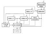
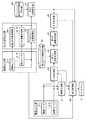
図17は、この発明の実施の形態3による監視装置を示す構成図である。図18は、この発明の実施の形態3による監視装置を示すハードウェア構成図である。
図17及び図18において、図1及び図2と同一符号は同一または相当部分を示すので説明を省略する。
画像センサ1−1〜1−Nは、図1の画像センサ1と同様に、例えば、光学カメラ又は赤外カメラなどで実現される。
画像センサ1−1〜1−Nは、目標物が存在している領域として、例えば、移動体が交通する空港敷地内及び空港周辺の領域を撮像して、前記領域の撮像画像を映像生成部31及び目標検出部32に出力する。
FIG. 17 is a block diagram showing a monitoring apparatus according toEmbodiment 3 of the present invention. FIG. 18 is a hardware configuration diagram showing a monitoring apparatus according toEmbodiment 3 of the present invention.
17 and 18, the same reference numerals as those in FIGS. 1 and 2 indicate the same or corresponding parts, and thus description thereof is omitted.
The image sensors 1-1 to 1-N are realized by, for example, an optical camera or an infrared camera, similarly to theimage sensor 1 of FIG.
The image sensors 1-1 to 1-N image, for example, an area in and around an airport site where a moving object is traveling as an area where the target is present, and a captured image of the area is generated as a video generation unit. 31 and thetarget detection unit 32.

映像生成部31は、例えば、図18に示す映像生成回路41で実現される。
映像生成部31は、画像センサ1−1〜1−Nから出力された撮像画像のそれぞれを表示処理部40に出力する。
また、映像生成部31は、画像センサ1−1〜1−Nから出力された撮像画像を合成することで、1つのパノラマ画像を生成し、パノラマ画像を撮像画像として目標検出部32及び表示処理部40に出力する。ここで、画像センサ1−1〜1−Nから出力された撮像画像を別々に、直接、撮像画像として目標検出部32及び表示処理部40に出力しても良いこととする。
Thevideo generation unit 31 is realized by, for example, avideo generation circuit 41 illustrated in FIG.
Thevideo generation unit 31 outputs each of the captured images output from the image sensors 1-1 to 1-N to thedisplay processing unit 40.
In addition, thevideo generation unit 31 generates one panoramic image by synthesizing the captured images output from the image sensors 1-1 to 1-N, and uses the panoramic image as a captured image to perform thetarget detection unit 32 and display processing. To theunit 40. Here, the captured images output from the image sensors 1-1 to 1-N may be directly output to thetarget detection unit 32 and thedisplay processing unit 40 directly as captured images.

目標検出部32は、例えば、図18に示す目標検出回路42で実現される。
目標検出部32は、画像センサ1−n(n=1,2,・・・,N)から出力された撮像画像内の目標物、あるいは、映像生成部31から出力された撮像画像内の目標物を検出する処理を実施する。
目標検出部32は、撮像画像上で検出した目標物の位置である目標物画像位置及び撮像画像上で目標物を包含している範囲である目標物包含画像領域のそれぞれを第1の追尾処理部33に出力する処理を実施する。
Thetarget detection unit 32 is realized by, for example, atarget detection circuit 42 illustrated in FIG.
Thetarget detection unit 32 is a target in the captured image output from the image sensor 1-n (n = 1, 2,..., N) or a target in the captured image output from thevideo generation unit 31. A process for detecting an object is performed.
Thetarget detection unit 32 performs a first tracking process on each of the target image position that is the position of the target detected on the captured image and the target-included image area that is a range including the target on the captured image. Processing to be output to theunit 33 is performed.

第1の追尾処理部33は、例えば、図18に示す第1の追尾処理回路43で実現される。
第1の追尾処理部33は、目標検出部32により検出された目標物の追尾処理を実施して、追尾処理後の目標物を包含している範囲である目標物包含画像領域を第1の判定処理部37に出力する処理を実施する。
第1の追尾処理部33が実施する目標物の追尾処理として、例えば、カルマンフィルタ、パーティクルフィルタなどを用いる公知の追尾処理を利用することができる。
The firsttracking processing unit 33 is realized by, for example, a firsttracking processing circuit 43 illustrated in FIG.
The firsttracking processing unit 33 performs tracking processing of the target detected by thetarget detection unit 32, and sets a target inclusion image area that is a range including the target after the tracking processing to the first. A process of outputting to thedetermination processing unit 37 is performed.
As the target tracking process performed by the firsttracking processing unit 33, for example, a known tracking process using a Kalman filter, a particle filter, or the like can be used.

観測センサ3−1〜3−Mは、図1の観測センサ3と同様に、例えば、ASR、MLAT、WAMなどで実現される。
観測センサ3−m(m=1,2,・・・,M)は、目標物を観測して、観測した目標物の識別情報及び目標物の3次元位置である目標物観測位置のそれぞれを第2の追尾処理部34−m及びマルチセンサ追尾処理部35に出力する。
The observation sensors 3-1 to 3-M are realized by, for example, ASR, MLAT, WAM, and the like, similarly to theobservation sensor 3 of FIG.
The observation sensor 3-m (m = 1, 2,..., M) observes the target, and identifies the identification information of the observed target and the target observation position that is the three-dimensional position of the target. The data is output to the second tracking processing unit 34-m and the multi-sensortracking processing unit 35.

第2の追尾処理部34−mは、例えば、図18に示す第2の追尾処理回路44で実現される。
第2の追尾処理部34−mは、観測センサ3−mから出力された目標物観測位置を用いて、目標物の追尾処理を実施し、追尾処理後の目標物の位置である目標物観測位置を変換処理部36に出力する処理を実施する。
また、第2の追尾処理部34−mは、観測センサ3−mから出力された目標物の識別情報を変換処理部36に出力する処理を実施する。
マルチセンサ追尾処理部35は、例えば、図18に示すマルチセンサ追尾処理回路45で実現される。
マルチセンサ追尾処理部35は、M個の観測センサ3−1〜3−Mから出力された目標物観測位置を用いて、目標物の追尾処理を実施し、追尾処理後の目標物の位置である目標物観測位置を変換処理部36に出力する処理を実施する。
マルチセンサ追尾処理部35は、第2の追尾処理部34−mと比べて、複数の目標物観測位置を用いる点でのみ相違している。
第2の追尾処理部34−m及びマルチセンサ追尾処理部35のそれぞれが実施する目標物の追尾処理として、例えば、カルマンフィルタ、パーティクルフィルタなどを用いる公知の追尾処理を利用することができる。
The second tracking processing unit 34-m is realized by, for example, the secondtracking processing circuit 44 illustrated in FIG.
The second tracking processing unit 34-m performs target tracking processing using the target observation position output from the observation sensor 3-m, and performs target observation that is the position of the target after the tracking processing. A process of outputting the position to theconversion processing unit 36 is performed.
In addition, the second tracking processing unit 34-m performs a process of outputting the identification information of the target output from the observation sensor 3-m to theconversion processing unit 36.
The multi-sensortracking processing unit 35 is realized by, for example, a multi-sensortracking processing circuit 45 illustrated in FIG.
The multi-sensortracking processing unit 35 performs target tracking processing using the target observation positions output from the M observation sensors 3-1 to 3-M, and uses the target position after the tracking processing. A process of outputting a target observation position to theconversion processing unit 36 is performed.
The multi-sensortracking processing unit 35 is different from the second tracking processing unit 34-m only in that a plurality of target object observation positions are used.
As the target tracking process performed by each of the second tracking processing unit 34-m and the multi-sensortracking processing unit 35, for example, a known tracking process using a Kalman filter, a particle filter, or the like can be used.

変換処理部36は、例えば、図18に示す変換処理回路46で実現される。
変換処理部36は、物体形状情報格納部4から、第2の追尾処理部34−m又はマルチセンサ追尾処理部35から出力された識別情報に対応する形状情報を読み出し、形状情報を参照することで、観測センサ3−mにより観測された目標物の大きさを特定する処理を実施する。
変換処理部36は、特定した目標物の大きさ及び第2の追尾処理部34−m又はマルチセンサ追尾処理部35から出力された目標物観測位置のそれぞれを画像センサ1−nの投影面に変換する処理を実施する。
変換処理部36は、変換した目標物の大きさと、変換した目標物観測位置とから、画像センサ1−nの投影面上で、観測センサ3−mにより観測された目標物を包含している範囲である目標物包含観測領域を特定する処理を実施する。
Theconversion processing unit 36 is realized by, for example, aconversion processing circuit 46 illustrated in FIG.
Theconversion processing unit 36 reads shape information corresponding to the identification information output from the second tracking processing unit 34-m or the multi-sensortracking processing unit 35 from the object shape information storage unit 4, and refers to the shape information. Then, the process of specifying the size of the target observed by the observation sensor 3-m is performed.
Theconversion processing unit 36 sets each of the identified target size and the target observation position output from the second tracking processing unit 34-m or the multi-sensortracking processing unit 35 on the projection plane of the image sensor 1-n. Perform the conversion process.
Theconversion processing unit 36 includes the target observed by the observation sensor 3-m on the projection plane of the image sensor 1-n from the converted target size and the converted target observation position. A process of specifying the target inclusion observation region that is a range is performed.

第1の判定処理部37は、例えば、図18に示す第1の判定処理回路47で実現される。
第1の判定処理部37は、変換処理部36により特定された目標物包含観測領域と、第1の追尾処理部33から出力された目標物包含画像領域とを比較して、観測センサ3−mにより観測された目標物と、目標検出部32により検出された目標物とが同一物であるか否かを判定する処理を実施する。
即ち、第1の判定処理部37は、画像センサ1−nの投影面上で、変換処理部36により特定された目標物包含観測領域と、第1の追尾処理部33から出力された目標物包含画像領域との重なり範囲を算出する処理を実施する。
また、第1の判定処理部37は、重なり範囲が閾値以上であれば、観測センサ3−mにより観測された目標物と、目標検出部32により検出された目標物とが同一物であると判定する処理を実施する。
第1の判定処理部37は、重なり範囲が閾値未満であれば、観測センサ3−mにより観測された目標物と、目標検出部32により検出された目標物とが同一物でないと判定する処理を実施する。
判定結果格納部38は、例えば、図18に示す判定結果記憶回路48で実現される。
判定結果格納部38は、第1の判定処理部37の判定結果を格納する。
The firstdetermination processing unit 37 is realized by, for example, a firstdetermination processing circuit 47 illustrated in FIG.
The firstdetermination processing unit 37 compares the target inclusion observation region specified by theconversion processing unit 36 with the target inclusion image region output from the firsttracking processing unit 33, and compares the observation sensor 3- A process of determining whether or not the target observed by m and the target detected by thetarget detection unit 32 are the same is performed.
That is, the firstdetermination processing unit 37 includes the target inclusion observation area specified by theconversion processing unit 36 on the projection plane of the image sensor 1-n and the target output from the firsttracking processing unit 33. A process of calculating an overlapping range with the inclusion image area is performed.
In addition, if the overlapping range is equal to or greater than the threshold, the firstdetermination processing unit 37 has the same target as the target observed by the observation sensor 3-m and the target detected by thetarget detection unit 32. Perform the process of determining.
If the overlapping range is less than the threshold value, the firstdetermination processing unit 37 determines that the target observed by the observation sensor 3-m and the target detected by thetarget detection unit 32 are not the same. To implement.
The determinationresult storage unit 38 is realized by, for example, a determinationresult storage circuit 48 illustrated in FIG.
The determinationresult storage unit 38 stores the determination result of the firstdetermination processing unit 37.

平滑処理部39は、例えば、図18に示す平滑処理回路49で実現される。
平滑処理部39は、第1の追尾処理部33から出力された目標物包含画像領域を時間方向に平滑化し、平滑化後の目標物包含画像領域を表示処理部40に出力する処理を実施する。
表示処理部40は、例えば、図2に示す表示処理回路50で実現される。
表示処理部40は、映像生成部31から出力された撮像画像をディスプレイ16に表示する処理を実施する。
表示処理部40は、第1の判定処理部37により同一物であると判定された場合、変換処理部36により画像センサ1−nの投影面に変換された目標物観測位置及び観測センサ3−mから出力された識別情報のそれぞれを撮像画像上に表示し、また、平滑処理部39から出力された平滑化後の目標物包含画像領域を撮像画像上に表示する処理を実施する。
The smoothingprocessing unit 39 is realized by, for example, a smoothingprocessing circuit 49 shown in FIG.
The smoothingprocessing unit 39 smoothes the target inclusion image area output from the firsttracking processing unit 33 in the time direction, and performs a process of outputting the smoothed target inclusion image area to thedisplay processing unit 40. .
Thedisplay processing unit 40 is realized by, for example, thedisplay processing circuit 50 shown in FIG.
Thedisplay processing unit 40 performs a process of displaying the captured image output from thevideo generation unit 31 on thedisplay 16.
When the firstdetermination processing unit 37 determines that thedisplay processing unit 40 is the same object, thedisplay processing unit 40 converts the target observation position and the observation sensor 3-converted to the projection plane of the image sensor 1-n by theconversion processing unit 36. Each of the identification information output from m is displayed on the captured image, and the smoothed target inclusion image area output from the smoothingprocessing unit 39 is displayed on the captured image.

図17では、監視装置の構成要素である画像センサ1−n、観測センサ3−m、映像生成部31、目標検出部32、第1の追尾処理部33、第2の追尾処理部34−m、マルチセンサ追尾処理部35、変換処理部36、第1の判定処理部37、判定結果格納部38、平滑処理部39、表示処理部40及びディスプレイ16のそれぞれが、図18に示すような専用のハードウェアで実現されるものを想定している。即ち、画像センサ1−n、観測センサ3−m、映像生成回路41、目標検出回路42、第1の追尾処理回路43、第2の追尾処理回路44、マルチセンサ追尾処理回路45、変換処理回路46、第1の判定処理回路47、判定結果記憶回路48、平滑処理回路49、表示処理回路50及びディスプレイ16で実現されるものを想定している。  In FIG. 17, the image sensor 1-n, the observation sensor 3-m, thevideo generation unit 31, thetarget detection unit 32, the firsttracking processing unit 33, and the second tracking processing unit 34-m, which are components of the monitoring device. Each of the multi-sensortracking processing unit 35, theconversion processing unit 36, the firstdetermination processing unit 37, the determinationresult storage unit 38, the smoothingprocessing unit 39, thedisplay processing unit 40, and thedisplay 16 is dedicated as shown in FIG. It is assumed that it is realized with hardware. That is, the image sensor 1-n, the observation sensor 3-m, thevideo generation circuit 41, thetarget detection circuit 42, the firsttracking processing circuit 43, the secondtracking processing circuit 44, the multi-sensortracking processing circuit 45, and the conversion processing circuit. 46, a firstdetermination processing circuit 47, a determinationresult storage circuit 48, a smoothingprocessing circuit 49, adisplay processing circuit 50, and adisplay 16 are assumed.

ここで、形状記憶回路12及び判定結果記憶回路48は、例えば、RAM、ROM、フラッシュメモリ、EPROM、EEPROMなどの不揮発性又は揮発性の半導体メモリや、磁気ディスク、フレキシブルディスク、光ディスク、コンパクトディスク、ミニディスク、DVDなどが該当する。
また、映像生成回路41、目標検出回路42、第1の追尾処理回路43、第2の追尾処理回路44、マルチセンサ追尾処理回路45、変換処理回路46、第1の判定処理回路47、平滑処理回路49及び表示処理回路50は、例えば、単一回路、複合回路、プログラム化したプロセッサ、並列プログラム化したプロセッサ、ASIC、FPGA、または、これらを組み合わせたものが該当する。
Here, theshape memory circuit 12 and the determinationresult memory circuit 48 include, for example, a nonvolatile or volatile semiconductor memory such as a RAM, a ROM, a flash memory, an EPROM, an EEPROM, a magnetic disk, a flexible disk, an optical disk, a compact disk, This includes minidiscs and DVDs.
Theimage generation circuit 41, thetarget detection circuit 42, the firsttracking processing circuit 43, the secondtracking processing circuit 44, the multi-sensortracking processing circuit 45, theconversion processing circuit 46, the firstdetermination processing circuit 47, and the smoothing process Thecircuit 49 and thedisplay processing circuit 50 are, for example, a single circuit, a composite circuit, a programmed processor, a processor programmed in parallel, an ASIC, an FPGA, or a combination thereof.

監視装置の画像センサ1−n、観測センサ3−m及びディスプレイ16を除く構成要素は、専用のハードウェアで実現されるものに限るものではなく、ソフトウェア、ファームウェア、または、ソフトウェアとファームウェアとの組み合わせで実現されるものであってもよい。  The components other than the image sensor 1-n, the observation sensor 3-m, and thedisplay 16 of the monitoring device are not limited to those realized by dedicated hardware, but are software, firmware, or a combination of software and firmware. It may be realized by.

監視装置の画像センサ1−n、観測センサ3−m及びディスプレイ16を除く構成要素がソフトウェア又はファームウェアなどで実現される場合、物体形状情報格納部4及び判定結果格納部38を図3に示すコンピュータのメモリ21上に構成するとともに、映像生成部31、目標検出部32、第1の追尾処理部33、第2の追尾処理部34−m、マルチセンサ追尾処理部35、変換処理部36、第1の判定処理部37、平滑処理部39及び表示処理部40の処理手順をコンピュータに実行させるためのプログラムをメモリ21に格納し、コンピュータのプロセッサ22がメモリ21に格納されているプログラムを実行するようにすればよい。  When components other than the image sensor 1-n, the observation sensor 3-m, and thedisplay 16 of the monitoring device are realized by software or firmware, the object shape information storage unit 4 and the determinationresult storage unit 38 are shown in FIG. Thevideo generation unit 31, thetarget detection unit 32, the firsttracking processing unit 33, the second tracking processing unit 34-m, the multi-sensortracking processing unit 35, theconversion processing unit 36, the first A program for causing the computer to execute the processing procedure of thedetermination processing unit 37, the smoothingprocessing unit 39, and thedisplay processing unit 40 is stored in thememory 21, and theprocessor 22 of the computer executes the program stored in thememory 21. What should I do?

次に動作について説明する。
画像センサ1−n(n=1,2,・・・,N)は、目標物が存在している領域として、例えば、移動体が交通する空港敷地内及び空港周辺の領域を撮像して、前記領域の撮像画像を目標検出部32及び映像生成部31に出力する。
映像生成部31は、画像センサ1−nから出力された撮像画像を表示処理部40に出力する。
また、映像生成部31は、画像センサ1−1〜1−Nから出力されたN個の撮像画像を合成することで、1つのパノラマ画像を生成し、パノラマ画像を撮像画像として目標検出部32及び表示処理部40に出力する。
Next, the operation will be described.
The image sensor 1-n (n = 1, 2,..., N), for example, images areas in and around the airport site where the mobile object is in traffic, The captured image of the area is output to thetarget detection unit 32 and thevideo generation unit 31.
Thevideo generation unit 31 outputs the captured image output from the image sensor 1-n to thedisplay processing unit 40.
In addition, thevideo generation unit 31 generates one panoramic image by synthesizing N captured images output from the image sensors 1-1 to 1-N, and uses the panoramic image as a captured image. And output to thedisplay processing unit 40.

目標検出部32は、画像センサ1−nから出力された撮像画像内の目標物、あるいは、映像生成部31から出力された撮像画像内の目標物を検出する処理を実施する。
撮像画像内の目標物を検出する処理自体は、公知の技術であるため詳細な説明を省略する。
この実施の形態3では、説明の簡単化のため、目標検出部32によって、1つの目標物が検出されるものとする。
目標検出部32は、撮像画像上で検出した目標物の位置である目標物画像位置と、検出した目標物を識別するIDとを第1の追尾処理部33及び表示処理部40に出力する。
また、目標検出部32は、撮像画像上で検出した目標物を包含している範囲である目標物包含画像領域を第1の追尾処理部33に出力する。
Thetarget detection unit 32 performs a process of detecting a target in the captured image output from the image sensor 1-n or a target in the captured image output from thevideo generation unit 31.
Since the process itself for detecting the target in the captured image is a known technique, detailed description thereof is omitted.
In the third embodiment, it is assumed that one target is detected by thetarget detection unit 32 for the sake of simplicity.
Thetarget detection unit 32 outputs a target image position, which is the position of the target detected on the captured image, and an ID for identifying the detected target to the firsttracking processing unit 33 and thedisplay processing unit 40.
In addition, thetarget detection unit 32 outputs a target inclusion image area that is a range including the target detected on the captured image to the firsttracking processing unit 33.

第1の追尾処理部33は、目標検出部32から出力された目標物画像位置を用いて、撮像画像内の目標物の追尾処理を実施し、追尾処理後の目標物を包含している範囲である目標物包含画像領域を第1の判定処理部37及び平滑処理部39に出力する。
第1の追尾処理部33による目標物の追尾処理は、目標検出部32から出力された目標物画像位置の時系列方向の相関を取る処理であり、例えば、カルマンフィルタを用いることができる。
なお、第1の追尾処理部33は、目標物包含画像領域を平滑化し、平滑後の目標物包含画像領域を第1の判定処理部37に出力するようにしてもよい。目標物包含画像領域を平滑化することで、目標物包含画像領域の変動が抑えられるため、第1の判定処理部37の判定精度を高めることができる。
The firsttracking processing unit 33 uses the target image position output from thetarget detection unit 32 to perform the tracking processing of the target in the captured image, and includes the target after the tracking processing. Is output to the firstdetermination processing unit 37 and the smoothingprocessing unit 39.
The target tracking process by the firsttracking processing unit 33 is a process for obtaining a correlation in the time series direction of the target image position output from thetarget detection unit 32, and for example, a Kalman filter can be used.
Note that the firsttracking processing unit 33 may smooth the target object including image region and output the smoothed target object including image region to the firstdetermination processing unit 37. By smoothing the target object including image area, fluctuations in the target object including image area can be suppressed, so that the determination accuracy of the firstdetermination processing unit 37 can be increased.

観測センサ3−m(m=1,2,・・・,M)は、目標物を観測して、観測した目標物の識別情報及び目標物の3次元位置である目標物観測位置を第2の追尾処理部34−m及びマルチセンサ追尾処理部35に出力する。
また、観測センサ3−mは、目標物の推定速度を示す速度ベクトルを第2の追尾処理部34−mに出力する。
この実施の形態3では、説明の簡単化のため、観測センサ3−mによって、1つの目標物が観測されるものとする。
The observation sensor 3-m (m = 1, 2,..., M) observes the target, and secondly identifies the identification information of the observed target and the target observation position that is the three-dimensional position of the target. Output to the tracking processing unit 34-m and the multi-sensortracking processing unit 35.
In addition, the observation sensor 3-m outputs a speed vector indicating the estimated speed of the target to the second tracking processing unit 34-m.
In the third embodiment, it is assumed that one target is observed by the observation sensor 3-m for simplification of description.

第2の追尾処理部34−mは、観測センサ3−mから出力された目標物観測位置及び速度ベクトルを用いて、観測センサ3−mにより観測された目標物の追尾処理を実施し、追尾処理後の目標物の位置である目標物観測位置を変換処理部36に出力する。
第2の追尾処理部34−mによる目標物の追尾処理は、観測センサ3−mから出力された目標物観測位置の時系列方向の相関を取る処理であり、例えば、カルマンフィルタを用いることができる。
また、第2の追尾処理部34−mは、観測センサ3−mから出力された目標物の識別情報及び追尾処理時に算出される推定誤差共分散行列などを変換処理部36に出力する。
推定誤差共分散行列は、目標物の追尾処理による推定誤差を示す推定誤差情報に相当する。
The second tracking processing unit 34-m performs tracking processing of the target observed by the observation sensor 3-m using the target observation position and velocity vector output from the observation sensor 3-m. The target observation position, which is the position of the target after processing, is output to theconversion processing unit 36.
The target tracking process by the second tracking processing unit 34-m is a process for obtaining a correlation in the time series direction of the target observation position output from the observation sensor 3-m. For example, a Kalman filter can be used. .
In addition, the second tracking processing unit 34-m outputs the target identification information output from the observation sensor 3-m, the estimated error covariance matrix calculated during the tracking process, and the like to theconversion processing unit 36.
The estimation error covariance matrix corresponds to estimation error information indicating an estimation error due to the target tracking process.

マルチセンサ追尾処理部35は、M個の観測センサ3−1〜3−Mから出力された目標物観測位置及び速度ベクトルを用いて、観測センサ3−mにより観測された目標物の追尾処理を実施し、追尾処理後の目標物の位置である目標物観測位置を変換処理部36に出力する。
また、マルチセンサ追尾処理部35は、追尾処理時に算出される推定誤差共分散行列などを変換処理部36に出力する。
マルチセンサ追尾処理部35が目標物の追尾処理を実施することで、M個の観測センサ3−1〜3−Mのうち、いずれかの観測センサが目標物の識別情報を取得できない場合でも、マルチセンサ追尾処理部35は、他の観測センサにより取得された識別情報を追尾処理後の目標物に対応付けることができる。
このため、マルチセンサ追尾処理部35は、M個の観測センサ3−1〜3−Mの中に、目標物の識別情報を取得できない観測センサが存在していても、追尾処理後の目標物の識別情報を変換処理部36に出力することができる。
The multi-sensortracking processing unit 35 uses the target observation position and velocity vector output from the M observation sensors 3-1 to 3-M to perform tracking processing of the target observed by the observation sensor 3-m. The target observation position, which is the position of the target after the tracking process, is output to theconversion processing unit 36.
In addition, the multi-sensortracking processing unit 35 outputs an estimated error covariance matrix or the like calculated during the tracking process to theconversion processing unit 36.
Even when any one of the M observation sensors 3-1 to 3-M cannot acquire the identification information of the target, the multi-sensortracking processing unit 35 performs the target tracking process. The multi-sensortracking processing unit 35 can associate the identification information acquired by other observation sensors with the target after the tracking process.
For this reason, the multi-sensortracking processing unit 35, even if an observation sensor that cannot acquire the identification information of the target exists among the M observation sensors 3-1 to 3-M, the target after the tracking process. The identification information can be output to theconversion processing unit 36.

変換処理部36は、物体形状情報格納部4から、第2の追尾処理部34−m又はマルチセンサ追尾処理部35から出力された識別情報に対応する形状情報を読み出し、形状情報を参照することで、観測センサ3−mにより観測された目標物の大きさを特定する。
変換処理部36は、特定した目標物の大きさ及び第2の追尾処理部34−m又はマルチセンサ追尾処理部35から出力された目標物観測位置のそれぞれを画像センサ1−nの投影面に変換する処理を実施する。
変換処理部36は、変換した目標物の大きさと、変換した目標物観測位置とから、画像センサ1−nの投影面上で、観測センサ3−mにより観測された目標物を包含している範囲である目標物包含観測領域を特定する。
変換処理部36の処理内容は、概ね、上記実施の形態2における変換処理部5の処理内容と同様であるが、以下の点で相違している。
Theconversion processing unit 36 reads shape information corresponding to the identification information output from the second tracking processing unit 34-m or the multi-sensortracking processing unit 35 from the object shape information storage unit 4, and refers to the shape information. Then, the size of the target observed by the observation sensor 3-m is specified.
Theconversion processing unit 36 sets each of the identified target size and the target observation position output from the second tracking processing unit 34-m or the multi-sensortracking processing unit 35 on the projection plane of the image sensor 1-n. Perform the conversion process.
Theconversion processing unit 36 includes the target observed by the observation sensor 3-m on the projection plane of the image sensor 1-n from the converted target size and the converted target observation position. A target inclusion observation area that is a range is specified.
The processing content of theconversion processing unit 36 is generally the same as the processing content of theconversion processing unit 5 in the second embodiment, but differs in the following points.

上記実施の形態2における変換処理部5は、目標物観測位置の観測誤差範囲を示す観測誤差情報に従って目標物包含観測領域を補正している。
これに対して、この実施の形態3における変換処理部36は、目標物観測位置の観測誤差範囲の代わりに、第2の追尾処理部34−m又はマルチセンサ追尾処理部35から出力された追尾処理による推定誤差を示す推定誤差共分散行列に従って目標物包含観測領域を補正する。
変換処理部36による目標物包含観測領域の補正処理自体は、変換処理部5による目標物包含観測領域の補正処理と同様であるため詳細な説明を省略するが、追尾処理による推定誤差の範囲は、目標物観測位置の観測誤差範囲と比べて狭い範囲となるため、上記実施の形態2よりも、更に同一物の判定精度を高めることができる。
Theconversion processing unit 5 in the second embodiment corrects the target inclusion observation area according to the observation error information indicating the observation error range of the target observation position.
On the other hand, theconversion processing unit 36 according to the third embodiment uses the tracking output from the second tracking processing unit 34-m or the multi-sensortracking processing unit 35 instead of the observation error range of the target observation position. The target inclusion observation area is corrected according to the estimation error covariance matrix indicating the estimation error due to the processing.
The correction process for the target inclusion observation area by theconversion processing unit 36 is the same as the correction process for the target inclusion observation area by theconversion processing unit 5 and will not be described in detail. However, the range of the estimation error by the tracking process is as follows. Since the range is narrower than the observation error range of the target object observation position, it is possible to further improve the accuracy of determining the same object as compared with the second embodiment.

第1の判定処理部37は、変換処理部36により補正された目標物包含観測領域と、第1の追尾処理部33から出力された目標物包含画像領域とを比較して、観測センサ3−mにより観測された目標物と、目標検出部32により検出された目標物とが同一物であるか否かを判定する。
即ち、第1の判定処理部37は、画像センサ1−nの投影面上で、変換処理部36により補正された目標物包含観測領域と、第1の追尾処理部33から出力された目標物包含画像領域との重なり範囲Ovを算出する。
The firstdetermination processing unit 37 compares the target inclusion observation region corrected by theconversion processing unit 36 with the target inclusion image region output from the firsttracking processing unit 33, and compares the observation sensor 3- It is determined whether or not the target observed by m and the target detected by thetarget detector 32 are the same.
In other words, the firstdetermination processing unit 37 includes the target inclusion observation area corrected by theconversion processing unit 36 on the projection plane of the image sensor 1-n and the target output from the firsttracking processing unit 33. An overlapping range Ov with the inclusion image area is calculated.

第1の判定処理部37は、算出した重なり範囲Ovと事前に設定された閾値Thとを比較する。
第1の判定処理部37は、重なり範囲Ovが閾値Th以上であれば、観測センサ3−mにより観測された目標物と、目標検出部32により検出された目標物とが同一物であると判定する。
第1の判定処理部37は、重なり範囲Ovが閾値Th未満であれば、観測センサ3により観測された目標物と、目標検出部32により検出された目標物とが同一物でないと判定する。
The firstdetermination processing unit 37 compares the calculated overlap range Ov with a preset threshold value Th.
If the overlap range Ov is equal to or greater than the threshold Th, the firstdetermination processing unit 37 has the same target as the target observed by the observation sensor 3-m and the target detected by thetarget detection unit 32. judge.
If the overlapping range Ov is less than the threshold Th, the firstdetermination processing unit 37 determines that the target observed by theobservation sensor 3 and the target detected by thetarget detection unit 32 are not the same.

第1の判定処理部37による判定処理の処理タイミングが、画像センサ1−nのフレームレートに対応している場合、第1の判定処理部37の処理負荷が大きくなり、画像センサ1−nのフレームレートで判定処理が終了しない場合がある。
そこで、第1の判定処理部37が、同一物であるか否かの判定結果を判定結果格納部38に格納し、一定期間中は、判定処理を実施せずに、判定結果格納部38に格納されている判定結果を読み出して、その判定結果を表示処理部40に出力するようにしてもよい。
また、第1の判定処理部37は、観測センサ3により観測された目標物と、目標検出部32により検出された目標物とが同一物であると判定した場合、目標物のID、目標物の識別情報、目標物包含画像領域及び目標物包含観測領域などの情報を判定結果格納部38に格納する。
そして、第1の判定処理部37は、判定結果格納部38に格納されている情報を、判定結果と一緒に表示処理部40に出力するようにしてもよい。
When the processing timing of the determination processing by the firstdetermination processing unit 37 corresponds to the frame rate of the image sensor 1-n, the processing load of the firstdetermination processing unit 37 increases, and the image sensor 1-n The determination process may not end at the frame rate.
Therefore, the firstdetermination processing unit 37 stores the determination result as to whether or not they are the same in the determinationresult storage unit 38, and does not perform the determination process for a certain period of time in the determinationresult storage unit 38. The stored determination result may be read and the determination result may be output to thedisplay processing unit 40.
Further, when the firstdetermination processing unit 37 determines that the target observed by theobservation sensor 3 and the target detected by thetarget detection unit 32 are the same, the ID of the target, the target Are stored in the determinationresult storage unit 38.
Then, the firstdetermination processing unit 37 may output the information stored in the determinationresult storage unit 38 to thedisplay processing unit 40 together with the determination result.

平滑処理部39は、以下の式(2)に示すように、第1の追尾処理部33から出力された目標物包含画像領域を時間方向に平滑化し、平滑化後の目標物包含画像領域を表示処理部40に出力する。

Figure 2018220745
式(2)において、Lkは、時刻tkにおける目標物包含画像領域の横幅(または縦幅)、Ls,k−1は、時刻tk−1における目標物包含画像領域の横幅推定値(または縦幅推定値)、Ls,kは、時刻tkにおける目標物包含画像領域の横幅推定値(または縦幅推定値)、aは係数である。
平滑処理部39が目標物包含画像領域を時間方向に平滑化することで、目標物包含画像領域の横幅又は縦幅の変動を抑えることができる。As shown in the following equation (2), the smoothingprocessing unit 39 smoothes the target object including image area output from the firsttracking processing unit 33 in the time direction, and the smoothed target object including image area is displayed. The data is output to thedisplay processing unit 40.
Figure 2018220745
In Equation (2), Lk is the horizontal width (or vertical width) of the target object including image area at time tk, and Ls, k−1 is the estimated horizontal width (or vertical width) of the target object including image area at time tk−1. (Estimated value), Ls, k is a lateral width estimated value (or vertical width estimated value) of the target object including image region at time tk, and a is a coefficient.
The smoothingprocessing unit 39 smoothes the target object-containing image area in the time direction, so that fluctuations in the horizontal width or the vertical width of the target object-containing image area can be suppressed.

表示処理部40は、映像生成部31から出力された画像センサ1−nの撮像画像、または、パノラマ画像である撮像画像をディスプレイ16に表示する。
表示処理部40は、第1の判定処理部37により同一物であると判定された場合、変換処理部36により画像センサ1の投影面に変換された目標物観測位置及び観測センサ3−mから出力された識別情報のそれぞれを撮像画像上に表示し、また、平滑処理部39から出力された平滑化後の目標物包含画像領域を撮像画像上に表示する。
Thedisplay processing unit 40 displays the captured image of the image sensor 1 -n output from thevideo generation unit 31 or the captured image that is a panoramic image on thedisplay 16.
When the firstdetermination processing unit 37 determines that thedisplay processing unit 40 is the same, thedisplay processing unit 40 uses the target observation position converted to the projection plane of theimage sensor 1 by theconversion processing unit 36 and the observation sensor 3-m. Each of the output identification information is displayed on the captured image, and the smoothed target object including image region output from the smoothingprocessing unit 39 is displayed on the captured image.

表示処理部40は、第1の判定処理部37により同一物でないと判定された場合、目標検出部32から出力された目標物画像位置及び平滑処理部39から出力された平滑化後の目標物包含画像領域と、目標検出部32から出力された目標物のIDとを撮像画像上に表示する。
あるいは、表示処理部7は、第1の判定処理部37により同一物でないと判定された場合、観測センサ3−mから出力された識別情報と、変換処理部36により画像センサ1−nの投影面に変換された目標物観測位置及び変換処理部36により補正された目標物包含観測領域とを撮像画像上に表示する。
When the firstdetermination processing unit 37 determines that thedisplay processing unit 40 is not the same object, thedisplay processing unit 40 outputs the target image position output from thetarget detection unit 32 and the target after smoothing output from the smoothingprocessing unit 39. The inclusion image region and the target ID output from thetarget detection unit 32 are displayed on the captured image.
Alternatively, when the firstdetermination processing unit 37 determines that thedisplay processing unit 7 is not the same object, thedisplay processing unit 7 projects the identification information output from the observation sensor 3-m and theconversion processing unit 36 projects the image sensor 1-n. The target observation position converted into the plane and the target inclusion observation area corrected by theconversion processing unit 36 are displayed on the captured image.

この実施の形態3では、第1の判定処理部37が、変換処理部36により補正された目標物包含観測領域と、第1の追尾処理部33から出力された目標物包含画像領域とを比較する例を示している。
しかし、観測センサ3−mは、画像センサ1−nと比べて、更新レートが低いため、観測センサ3−mの観測時刻と、画像センサ1−nの撮像時刻との間に時刻差を生じることがある。上記の時刻差は、第1の判定処理部37の判定精度の劣化要因になる。
また、観測センサ3−mの観測時刻と、画像センサ1−nの撮像時刻とが同じ時刻であっても、観測センサ3−mと第1の判定処理部37間のデータ遅延時間と、画像センサ1−nと第1の判定処理部37間のデータ遅延時間との間に時間差を生じることがある。上記の時間差は、第1の判定処理部37の判定精度の劣化要因になる。
In the third embodiment, the firstdetermination processing unit 37 compares the target inclusion including observation area corrected by theconversion processing unit 36 with the target inclusion image area output from the firsttracking processing unit 33. An example is shown.
However, since the observation sensor 3-m has a lower update rate than the image sensor 1-n, a time difference is generated between the observation time of the observation sensor 3-m and the imaging time of the image sensor 1-n. Sometimes. The time difference is a cause of deterioration in the determination accuracy of the firstdetermination processing unit 37.
Even if the observation time of the observation sensor 3-m and the imaging time of the image sensor 1-n are the same time, the data delay time between the observation sensor 3-m and the firstdetermination processing unit 37, and the image There may be a time difference between the data delay time between the sensor 1-n and the firstdetermination processing unit 37. The time difference is a cause of deterioration in the determination accuracy of the firstdetermination processing unit 37.

そこで、第1の判定処理部37が、以下のようにして、判定精度の劣化要因を解消するようにしてもよい。
まず、第1の判定処理部37は、例えば、画像センサ1−nの更新レートに対応する更新時刻tを設定する。
第1の判定処理部37は、観測センサ3−mの観測時刻が更新時刻tよりも遅れている場合、更新時刻tと、第2の追尾処理部34−mから目標物観測位置が出力される時刻t’又はマルチセンサ追尾処理部35から目標物観測位置が出力される時刻t’との時刻差(t−t’)を算出する。
Therefore, the firstdetermination processing unit 37 may eliminate the deterioration factor of the determination accuracy as follows.
First, the firstdetermination processing unit 37 sets an update time t corresponding to the update rate of the image sensor 1-n, for example.
When the observation time of the observation sensor 3-m is behind the update time t, the firstdetermination processing unit 37 outputs the update time t and the target observation position from the second tracking processing unit 34-m. Or a time difference (t−t ′) from the time t ′ when the target observation position is output from the multi-sensortracking processing unit 35.

次に、第1の判定処理部37は、時刻差(t−t’)によって、以下の式(3)に示すように、例えば、第2の追尾処理部34−mの追尾処理で算出される推定状態ベクトルxハットtを時間外挿する。明細書の文章中では、電子出願の関係上、xの文字の上に“^”の記号を付することができないので、「xハットt」のように表記している。推定状態ベクトルxハットtは、第2の追尾処理部34−m等による追尾処理後の時刻tの目標物観測位置に相当する。
式(3)におけるΦ(t−t’)は、例えば、以下の式(4)に示すように、等速直線運動モデルの状態推移行列として定義することができる。

Figure 2018220745

Figure 2018220745
式(4)において、In×nは、n行n列の単位行列、On×nは、n行n列の零行列である。Next, the firstdetermination processing unit 37 is calculated by the tracking process of the second tracking processing unit 34-m, for example, as shown in the following equation (3), based on the time difference (t−t ′). The estimated state vector xhat t is extrapolated in time. In the text of the specification, the symbol “^” cannot be added above the letter x because of the electronic application, so it is represented as “x hat t”. The estimated state vector x hat t corresponds to the target observation position at time t after the tracking processing by the second tracking processing unit 34-m or the like.
Φ (t−t ′) in equation (3) can be defined as a state transition matrix of a constant velocity linear motion model, for example, as shown in equation (4) below.
Figure 2018220745

Figure 2018220745
In Expression (4), In × n is an n × n unit matrix, and On × n is an n × n zero matrix.

また、第1の判定処理部37は、時刻差(t−t’)によって、以下の式(5)に示すように、例えば、第2の追尾処理部34−mの追尾処理による推定誤差を示す推定誤差共分散行列Ptを時間外挿する。

Figure 2018220745
式(5)において、Q(t−t’)は、駆動雑音共分散行列である。
第1の判定処理部37が、時間外挿した推定状態ベクトルxハットtである追尾処理後の目標物観測位置及び時間外挿した推定誤差共分散行列Ptを変換処理部36に出力することで、時刻差(t−t’)による判定精度の劣化要因が解消される。Further, the firstdetermination processing unit 37 calculates the estimation error due to the tracking process of the second tracking processing unit 34-m, for example, as shown in the following equation (5), based on the time difference (t−t ′). The estimated error covariance matrix Pt shown is extrapolated in time.
Figure 2018220745
In Equation (5), Q (t−t ′) is a drive noise covariance matrix.
The firstdetermination processing unit 37 outputs, to theconversion processing unit 36, the target observation position after tracking processing and the extrapolated estimated error covariance matrix Pt, which are the estimated state vector x hat t extrapolated in time. , The cause of deterioration of the determination accuracy due to the time difference (t−t ′) is eliminated.

以上で明らかなように、この実施の形態3によれば、目標検出部32により検出された目標物の追尾処理を実施して、追尾処理後の目標物を包含している範囲である目標物包含画像領域を第1の判定処理部37に出力する第1の追尾処理部33と、観測センサ3−mにより観測された目標物の追尾処理を実施して、追尾処理後の目標物の位置である目標物観測位置を変換処理部36に出力する第2の追尾処理部34−mとを備えている。これにより、画像センサ1−nによる目標物の撮像誤差及び観測センサ3−mによる目標物の観測誤差のそれぞれが抑圧される。その結果、上記実施の形態1よりも、更に、同一物の判定精度を高めることができる効果を奏する。  As is apparent from the above, according to the third embodiment, the target that is the range including the target after the tracking process is performed by performing the tracking process of the target detected by thetarget detection unit 32. The firsttracking processing unit 33 that outputs the inclusion image region to the firstdetermination processing unit 37 and the tracking processing of the target observed by the observation sensor 3-m are performed, and the position of the target after the tracking processing is performed. And a second tracking processing unit 34-m for outputting the target observation position to theconversion processing unit 36. Thereby, each of the imaging error of the target by the image sensor 1-n and the observation error of the target by the observation sensor 3-m are suppressed. As a result, there is an effect that the accuracy of determination of the same object can be further improved as compared with the first embodiment.

実施の形態4.
上記実施の形態1〜3では、監視装置が第1の判定処理部6又は第1の判定処理部37を備えている例を示している。
この実施の形態4では、監視装置が第1の判定処理部37、第2の判定処理部62及び第3の判定処理部64を備えている例を説明する。
また、この実施の形態4では、上記実施の形態1〜3と異なり、同一物の判定に画像上ではなく、地図座標における位置を用いることを特徴としている。
Embodiment 4 FIG.
In the first to third embodiments, an example in which the monitoring device includes the firstdetermination processing unit 6 or the firstdetermination processing unit 37 is shown.
In the fourth embodiment, an example in which the monitoring device includes a firstdetermination processing unit 37, a seconddetermination processing unit 62, and a thirddetermination processing unit 64 will be described.
Further, the fourth embodiment is characterized in that, unlike the first to third embodiments, the position in the map coordinates is used for determining the same object, not on the image.

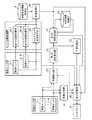
図19は、この発明の実施の形態4による監視装置を示す構成図である。図20は、この発明の実施の形態4による監視装置を示すハードウェア構成図である。
図19及び図20において、図1、図2、図17及び図18と同一符号は同一または相当部分を示すので説明を省略する。
観測位置射影部61は、例えば、図20に示す観測位置射影回路71で実現される。
観測位置射影部61は、第2の追尾処理部34−mから出力された目標物観測位置又はマルチセンサ追尾処理部35から出力された目標物観測位置を、画像センサ1−nの視線方向に移動したときに、地上面と交差する位置を射影位置として算出する処理を実施する。
FIG. 19 is a block diagram showing a monitoring apparatus according to Embodiment 4 of the present invention. FIG. 20 is a hardware configuration diagram showing a monitoring apparatus according to Embodiment 4 of the present invention.
19 and 20, the same reference numerals as those in FIGS. 1, 2, 17, and 18 indicate the same or corresponding parts, and thus description thereof is omitted.
The observationposition projection unit 61 is realized by, for example, an observationposition projection circuit 71 shown in FIG.
The observationposition projection unit 61 sets the target observation position output from the second tracking processing unit 34-m or the target observation position output from the multi-sensortracking processing unit 35 in the line-of-sight direction of the image sensor 1-n. When moving, a process of calculating a position intersecting the ground surface as a projection position is performed.

第2の判定処理部62は、例えば、図20に示す第2の判定処理回路72で実現される。
第2の判定処理部62は、観測位置射影部61により算出された射影位置と目標検出部32bから出力された目標物地図座標位置とを比較して、観測センサ3−mにより観測された目標物と、目標検出部32bにより検出された目標物とが同一物であるか否かを判定する処理を実施する。
ここで、目標検出部32bは、図17の目標検出部32と同様に、目標物を検出する処理を実施する。
ただし、目標検出部32bが、目標物地図座標位置を算出する方法としては、画像上での目標物画素位置より、予め用意していた地図DBを用いて、地図上の座標位置と照合する方法でも良い。一方、飛行中の目標物については、地上を走行する目標物でないことから、地図との照合が困難であるため、図21のように、画像センサ視線方向ベクトルを延長し、水平面と交差する位置を目標物地図座標位置として出力しても良いこととする。
The seconddetermination processing unit 62 is realized by, for example, a seconddetermination processing circuit 72 illustrated in FIG.
The seconddetermination processing unit 62 compares the projection position calculated by the observationposition projection unit 61 with the target map coordinate position output from thetarget detection unit 32b, and compares the target observed by the observation sensor 3-m. A process of determining whether or not the object and the target detected by thetarget detection unit 32b are the same is performed.
Here, thetarget detection unit 32b performs a process of detecting a target, similarly to thetarget detection unit 32 of FIG.
However, as a method for calculating the target map coordinate position by thetarget detection unit 32b, a method of collating with the coordinate position on the map from the target pixel position on the image by using the prepared map DB. But it ’s okay. On the other hand, since the target in flight is not a target traveling on the ground, it is difficult to collate with the map. Therefore, as shown in FIG. 21, the image sensor line-of-sight direction vector is extended and the position intersects the horizontal plane. May be output as the target map coordinate position.

第3の追尾処理部63は、例えば、図20に示す第3の追尾処理回路73で実現される。
第3の追尾処理部63は、目標検出部32bにより検出された1つ以上の目標物のうち、第2の判定処理部62により同一物であると判定された目標物以外の目標物の追尾処理を実施して、追尾処理後の目標物の位置である目標物地図座標位置を出力する処理を実施する。
The thirdtracking processing unit 63 is realized by, for example, a thirdtracking processing circuit 73 shown in FIG.
The thirdtracking processing unit 63 tracks the target other than the target determined to be the same by the seconddetermination processing unit 62 among the one or more targets detected by thetarget detection unit 32b. A process is implemented and the process which outputs the target object map coordinate position which is the position of the target object after a tracking process is implemented.

第3の判定処理部64は、例えば、図20に示す第3の判定処理回路74で実現される。
第3の判定処理部64は、第2の追尾処理部34−mから出力された目標物観測位置又はマルチセンサ追尾処理部35から出力された目標物観測位置と、第3の追尾処理部63から出力された目標物包含画像領域とを比較して、観測センサ3−mにより観測された目標物と、目標検出部32bにより検出された目標物とが同一物であるか否かを判定する処理を実施する。
目標物選択部65は、例えば、図20に示す目標物選択回路75で実現される。
目標物選択部65は、第1の判定処理部37、第2の判定処理部62又は第3の判定処理部64により同一物であると判定された目標物の中から、1つ以上の目標物を選択する処理を実施する。
The thirddetermination processing unit 64 is realized by, for example, a thirddetermination processing circuit 74 illustrated in FIG.
The thirddetermination processing unit 64 includes the target observation position output from the second tracking processing unit 34-m or the target observation position output from the multi-sensortracking processing unit 35, and the thirdtracking processing unit 63. Is compared with the target object including image region output from the target object, and it is determined whether or not the target object observed by the observation sensor 3-m and the target object detected by thetarget detector 32b are the same. Perform the process.
Thetarget selection unit 65 is realized by, for example, atarget selection circuit 75 shown in FIG.
Thetarget selection unit 65 includes one or more targets among the targets determined to be the same by the firstdetermination processing unit 37, the seconddetermination processing unit 62, or the thirddetermination processing unit 64. A process of selecting an object is performed.

図19の監視装置は、観測位置射影部61、第2の判定処理部62、第3の追尾処理部63、第3の判定処理部64及び目標物選択部65が図17の監視装置に適用されている例を示しているが、図1の監視装置に適用されているものであってもよい。
図19では、監視装置の構成要素である画像センサ1−n、観測センサ3−m、映像生成部31、目標検出部32b、第1の追尾処理部33、第2の追尾処理部34−m、マルチセンサ追尾処理部35、変換処理部36、第1の判定処理部37、判定結果格納部38、平滑処理部39、表示処理部40、観測位置射影部61、第2の判定処理部62、第3の追尾処理部63、第3の判定処理部64、目標物選択部65及びディスプレイ16のそれぞれが、図20に示すような専用のハードウェアで実現されるものを想定している。即ち、画像センサ1−n、観測センサ3−m、映像生成回路41、目標検出回路42、第1の追尾処理回路43、第2の追尾処理回路44、マルチセンサ追尾処理回路45、変換処理回路46、第1の判定処理回路47、判定結果記憶回路48、平滑処理回路49、表示処理回路50、観測位置射影回路71、第2の判定処理回路72、第3の追尾処理回路73、第3の判定処理回路74、目標物選択回路75及びディスプレイ16で実現されるものを想定している。
In the monitoring device of FIG. 19, the observationposition projection unit 61, the seconddetermination processing unit 62, the thirdtracking processing unit 63, the thirddetermination processing unit 64, and thetarget selection unit 65 are applied to the monitoring device of FIG. However, it may be applied to the monitoring apparatus of FIG.
In FIG. 19, the image sensor 1-n, the observation sensor 3-m, thevideo generation unit 31, thetarget detection unit 32b, the firsttracking processing unit 33, and the second tracking processing unit 34-m, which are components of the monitoring device. The multi-sensortracking processing unit 35, theconversion processing unit 36, the firstdetermination processing unit 37, the determinationresult storage unit 38, the smoothingprocessing unit 39, thedisplay processing unit 40, the observationposition projection unit 61, and the seconddetermination processing unit 62. It is assumed that each of the thirdtracking processing unit 63, the thirddetermination processing unit 64, thetarget selection unit 65, and thedisplay 16 is realized by dedicated hardware as shown in FIG. That is, the image sensor 1-n, the observation sensor 3-m, thevideo generation circuit 41, thetarget detection circuit 42, the firsttracking processing circuit 43, the secondtracking processing circuit 44, the multi-sensortracking processing circuit 45, and the conversion processing circuit. 46, firstdetermination processing circuit 47, determinationresult storage circuit 48, smoothingprocessing circuit 49,display processing circuit 50, observationposition projection circuit 71, seconddetermination processing circuit 72, thirdtracking processing circuit 73, third Are assumed to be realized by thedetermination processing circuit 74, thetarget selection circuit 75, and thedisplay 16.

映像生成回路41、目標検出回路42、第1の追尾処理回路43、第2の追尾処理回路44、マルチセンサ追尾処理回路45、変換処理回路46、第1の判定処理回路47、平滑処理回路49、表示処理回路50、観測位置射影回路71、第2の判定処理回路72、第3の追尾処理回路73、第3の判定処理回路74及び目標物選択回路75は、例えば、単一回路、複合回路、プログラム化したプロセッサ、並列プログラム化したプロセッサ、ASIC、FPGA、または、これらを組み合わせたものが該当する。  Video generation circuit 41,target detection circuit 42, firsttracking processing circuit 43, secondtracking processing circuit 44, multi-sensortracking processing circuit 45,conversion processing circuit 46, firstdetermination processing circuit 47, smoothingprocessing circuit 49 Thedisplay processing circuit 50, the observationposition projection circuit 71, the seconddetermination processing circuit 72, the thirdtracking processing circuit 73, the thirddetermination processing circuit 74, and thetarget selection circuit 75 are, for example, a single circuit, a composite A circuit, a programmed processor, a parallel programmed processor, an ASIC, an FPGA, or a combination thereof is applicable.

監視装置の画像センサ1−n、観測センサ3−m及びディスプレイ16を除く構成要素は、専用のハードウェアで実現されるものに限るものではなく、ソフトウェア、ファームウェア、または、ソフトウェアとファームウェアとの組み合わせで実現されるものであってもよい。
監視装置の画像センサ1−n、観測センサ3−m及びディスプレイ16を除く構成要素がソフトウェア又はファームウェアなどで実現される場合、物体形状情報格納部4及び判定結果格納部38を図3に示すコンピュータのメモリ21上に構成するとともに、映像生成部31、目標検出部32b、第1の追尾処理部33、第2の追尾処理部34−m、マルチセンサ追尾処理部35、変換処理部36、第1の判定処理部37、平滑処理部39、表示処理部40、観測位置射影部61、第2の判定処理部62、第3の追尾処理部63、第3の判定処理部64及び目標物選択部65の処理手順をコンピュータに実行させるためのプログラムをメモリ21に格納し、コンピュータのプロセッサ22がメモリ21に格納されているプログラムを実行するようにすればよい。
The components other than the image sensor 1-n, the observation sensor 3-m, and thedisplay 16 of the monitoring device are not limited to those realized by dedicated hardware, but are software, firmware, or a combination of software and firmware. It may be realized by.
When components other than the image sensor 1-n, the observation sensor 3-m, and thedisplay 16 of the monitoring device are realized by software or firmware, the object shape information storage unit 4 and the determinationresult storage unit 38 are shown in FIG. Thevideo generation unit 31, thetarget detection unit 32b, the firsttracking processing unit 33, the second tracking processing unit 34-m, the multi-sensortracking processing unit 35, theconversion processing unit 36, the first 1determination processing unit 37, smoothingprocessing unit 39,display processing unit 40, observationposition projection unit 61, seconddetermination processing unit 62, thirdtracking processing unit 63, thirddetermination processing unit 64, and target selection The program for causing the computer to execute the processing procedure of theunit 65 is stored in thememory 21, and theprocessor 22 of the computer executes the program stored in thememory 21. It may be set to cormorants.

次に動作について説明する。
観測位置射影部61は、図21に示すように、第2の追尾処理部34−mから出力された目標物観測位置又はマルチセンサ追尾処理部35から出力された目標物観測位置を、画像センサ1−nの視線方向に移動したときに、地上面と交差する位置を射影位置として算出する。
図21は、観測位置射影部61により算出される射影位置を示す説明図である。
図22は、観測位置射影部61により算出される射影位置と、目標検出部32bから出力される目標物地図座標位置との関係を示す説明図である。
観測センサ3−mにより観測された目標物と、目標検出部32bにより検出された目標物である撮像画像上の目標物とが同一物であれば、図22に示している射影位置と目標物地図座標位置との距離が短いが、同一物でなければ、射影位置と目標物地図座標位置との距離が長い。
Next, the operation will be described.
As shown in FIG. 21, the observationposition projection unit 61 uses the target observation position output from the second tracking processing unit 34-m or the target observation position output from the multi-sensortracking processing unit 35 as an image sensor. A position that intersects the ground surface when moving in the 1-n line-of-sight direction is calculated as a projection position.
FIG. 21 is an explanatory diagram showing the projection position calculated by the observationposition projection unit 61.
FIG. 22 is an explanatory diagram showing the relationship between the projection position calculated by the observationposition projection unit 61 and the target object map coordinate position output from thetarget detection unit 32b.
If the target observed by the observation sensor 3-m and the target on the captured image, which is the target detected by thetarget detector 32b, are the same, the projected position and target shown in FIG. Although the distance from the map coordinate position is short, if it is not the same object, the distance between the projection position and the target map coordinate position is long.

第2の判定処理部62は、観測位置射影部61により算出された射影位置と、目標検出部32bから出力された目標物地図座標位置とを比較して、観測センサ3−mにより観測された目標物と、目標検出部32bにより検出された目標物とが同一物であるか否かを判定する。
図23は、第2の判定処理部62の処理内容を示すフローチャートである。
以下、図23を参照しながら、第2の判定処理部62の処理内容を具体的に説明する。
この実施の形態4では、目標検出部32bによって、I個の目標物が検出され、観測センサ3−mによって、J個の目標物が観測されているものとする。
The seconddetermination processing unit 62 compares the projection position calculated by the observationposition projection unit 61 with the target map coordinate position output from thetarget detection unit 32b, and is observed by the observation sensor 3-m. It is determined whether the target and the target detected by thetarget detection unit 32b are the same.
FIG. 23 is a flowchart showing the processing contents of the seconddetermination processing unit 62.
Hereinafter, the processing content of the seconddetermination processing unit 62 will be specifically described with reference to FIG.
In the fourth embodiment, it is assumed that I target objects are detected by thetarget detection unit 32b, and J target objects are observed by the observation sensor 3-m.

第2の判定処理部62は、第2の追尾処理部34−m又はマルチセンサ追尾処理部35から目標物j(j=1,2,・・・,J)の目標物観測位置を受けると、目標物jの高度Zを認識する。
第2の判定処理部62は、目標物jの高度Zと事前に設定された閾値Zthとを比較する(図23のステップST11)。
第2の判定処理部62は、目標物jの高度Zが閾値Zth以上であれば(図23のステップST11:YESの場合)、目標物jが飛行中の移動体であると認識する(図23のステップST12)。
第2の判定処理部62は、目標物jの高度Zが閾値Zth未満であれば(図23のステップST11:NOの場合)、目標物jが地上に存在している移動体であると認識する(図23のステップST13)。地上に存在している移動体には、停止中の移動体も含まれる。
When the seconddetermination processing unit 62 receives the target observation position of the target j (j = 1, 2,..., J) from the second tracking processing unit 34-m or the multi-sensortracking processing unit 35. , Recognize the altitude Z of the target j.
The seconddetermination processing unit 62 compares the altitude Z of the target j with a preset threshold value Zth (step ST11 in FIG. 23).
If the altitude Z of the target j is greater than or equal to the threshold Zth (step ST11 in FIG. 23: YES), the seconddetermination processing unit 62 recognizes that the target j is a moving object in flight (FIG. 23 step ST12).
If the altitude Z of the target j is less than the threshold value Zth (step ST11 in FIG. 23: NO), the seconddetermination processing unit 62 recognizes that the target j is a moving object existing on the ground. (Step ST13 in FIG. 23). The moving objects existing on the ground include moving objects that are stopped.

第2の判定処理部62は、目標物jが飛行中の移動体であると認識すると、飛行中の移動体である目標物jと、目標検出部32bにより検出された目標物i(i=1,2,・・・,I)とが同一物であるか否かを判定する。
具体的には、第2の判定処理部62は、観測位置射影部61により算出された目標物jの射影位置を取得する(図23のステップST14)。
When the seconddetermination processing unit 62 recognizes that the target j is a moving object in flight, the target j that is the moving object in flight and the target i (i = i = i) detected by the target detecting unit 32b. 1, 2,..., I) are determined to be the same.
Specifically, the seconddetermination processing unit 62 acquires the projection position of the target j calculated by the observation position projection unit 61 (step ST14 in FIG. 23).

次に、第2の判定処理部62は、例えば、以下の式(6)に示すように、観測位置射影部61により算出された目標物jの射影位置と、目標検出部32bから出力された目標物iの目標物地図座標位置とを用いて、カイ二乗検定の検定値εを算出する(図23のステップST15)。

Figure 2018220745
式(6)において、
xハットxt,j,HETは、観測位置射影部61により算出された目標物jの時刻tにおける射影位置を示す推定位置ベクトル
xハットxt,j,CAMは、目標検出部32bにより検出された目標物iの時刻tにおける目標物地図座標位置を示す推定位置ベクトル
Pt,j,HETは、第2の追尾処理部34−m又はマルチセンサ追尾処理部35の追尾処理による目標物jの時刻tにおける推定位置誤差を示す推定誤差共分散行列
Pt,i,CAMは、目標検出部32bにより検出された目標物iの時刻tにおける推定位置誤差を示す推定誤差共分散行列Next, the seconddetermination processing unit 62 outputs the projection position of the target j calculated by the observationposition projection unit 61 and thetarget detection unit 32b, for example, as shown in the following equation (6). A test value ε of chi-square test is calculated using the target map coordinate position of the target i (step ST15 in FIG. 23).
Figure 2018220745
In equation (6),
xhat xt, j, HET is an estimated position vector xhatxt, j, CAM indicating the projected position of the target j calculated at the time t calculated by the observationposition projecting unit 61, and the target detected by thetarget detecting unit 32b. The estimated position vector Pt, j, HET indicating the target map coordinate position of the object i at the time t is the target j at the time t by the tracking process of the second tracking processing unit 34-m or the multi-sensortracking processing unit 35. The estimated error covariance matrix Pt, i, CAM indicating the estimated position error is an estimated error covariance matrix indicating the estimated position error of the target i detected by thetarget detection unit 32b at time t.

次に、第2の判定処理部62は、以下の式(7)に示すように、カイ二乗検定の検定値εと事前に設定された閾値εthとを比較する(図23のステップST16)。

Figure 2018220745
閾値εthは、所定の有意水準に基づいて、例えば、カイ二乗分布表から求めたものである。
例えば、有意水準を5%として検定すると、危険率5%で、本来同一である航跡が、同一でない航跡と誤った判定がなされることを意味する。
第2の判定処理部62は、カイ二乗検定の検定値εが閾値εth未満であれば(図23のステップST16:YESの場合)、飛行中の移動体である目標物jと、目標検出部32bにより検出された目標物iとが同一物であると判定する(図23のステップST17)。
第2の判定処理部62は、カイ二乗検定の検定値εが閾値εth以上であれば(図23のステップST16:NOの場合)、飛行中の移動体である目標物jと、目標検出部32bにより検出された目標物iとが同一物でないと判定する(図23のステップST18)。
第2の判定処理部62は、目標物iと同一物であると判定した目標物jの識別情報を第3の判定処理部64及び目標物選択部65に出力し、目標物jと同一物であると判定した目標物iのIDを第3の追尾処理部63に出力する。
第2の判定処理部62による飛行中の移動体である目標物jと、目標検出部32bにより検出された目標物iとの同一物か否かの判定処理は、飛行中の移動体である目標物jと目標検出部32bにより検出された目標物iとの全ての組み合わせについて行われる。Next, as shown in the following equation (7), the seconddetermination processing unit 62 compares the test value ε of the chi-square test with a preset threshold value εth (step ST16 in FIG. 23).
Figure 2018220745
The threshold value εth is obtained from, for example, a chi-square distribution table based on a predetermined significance level.
For example, a test with a significance level of 5% means that a wake that is originally the same with a risk rate of 5% is erroneously determined as a wake that is not the same.
If the test value ε of the chi-square test is less than the threshold value εth (in the case of step ST16: YES in FIG. 23), the seconddetermination processing unit 62 and the target object j that is a moving object in flight and the target detection unit It determines with the target object i detected by 32b being the same thing (step ST17 of FIG. 23).
If the test value ε of the chi-square test is equal to or greater than the threshold value εth (in the case of step ST16 in FIG. 23: NO), the seconddetermination processing unit 62 and the target j that is a moving object in flight and the target detection unit It is determined that the target object i detected by 32b is not the same object (step ST18 in FIG. 23).
The seconddetermination processing unit 62 outputs the identification information of the target j determined to be the same as the target i to the thirddetermination processing unit 64 and thetarget selection unit 65, and is the same as the target j. The ID of the target i determined to be is output to the thirdtracking processing unit 63.
The determination process of whether or not the target object j which is a moving object in flight by the seconddetermination processing unit 62 and the target object i detected by thetarget detecting unit 32b is the same object is the moving object in flight. This is performed for all combinations of the target j and the target i detected by thetarget detector 32b.

第3の追尾処理部63は、目標検出部32bから出力されたI個の目標物のIDと、第2の判定処理部62から出力された目標物iのIDとを比較し、I個の目標物の中から、目標物iのIDと異なるIDを有する目標物fを選択する。
第3の追尾処理部63は、目標検出部32bから出力されたI個の目標物の目標物地図座標位置のうち、選択した目標物fについての目標物地図座標位置を用いて、目標物fの追尾処理を実施する。
第3の追尾処理部63は、追尾処理後の目標物fの位置である目標物観測位置を第3の判定処理部64に出力する。
第3の追尾処理部63による目標物fの追尾処理は、選択した目標物fについての目標物地図座標位置の時系列方向の相関を取る処理であり、例えば、カルマンフィルタを用いることができる。
The thirdtracking processing unit 63 compares the IDs of the I targets output from thetarget detection unit 32b with the IDs of the target i output from the seconddetermination processing unit 62, and I A target f having an ID different from the ID of the target i is selected from the targets.
The thirdtracking processing unit 63 uses the target object map coordinate position for the selected target object f out of the target object map coordinate positions of the I target objects output from thetarget detection unit 32b, and uses the target object f. Execute the tracking process.
The thirdtracking processing unit 63 outputs the target observation position, which is the position of the target f after the tracking processing, to the thirddetermination processing unit 64.
The tracking process of the target f by the thirdtracking processing unit 63 is a process for obtaining a correlation in the time series direction of the target map coordinate position for the selected target f, and for example, a Kalman filter can be used.

第3の判定処理部64は、第2の追尾処理部34−m又はマルチセンサ追尾処理部35から出力されたJ個の目標物の識別情報と、第2の判定処理部62から出力された目標物jの識別情報とを比較し、J個の目標物の中から、目標物jの識別情報と異なる識別情報を有する目標物gを選択する。
第3の判定処理部64は、第2の追尾処理部34−m又はマルチセンサ追尾処理部35から出力されたJ個の目標物の目標物観測位置の中から、選択した目標物gの目標物観測位置を選択する。
第3の判定処理部64は、選択した目標物gの目標物観測位置と、第3の追尾処理部63から出力された目標物fの目標物地図座標位置とを比較して、観測センサ3−mにより観測された目標物gと、目標検出部32bにより検出された目標物fとが同一物であるか否かを判定する。
以下、第3の判定処理部64の処理内容を具体的に説明する。
The thirddetermination processing unit 64 outputs the identification information of J targets output from the second tracking processing unit 34-m or the multi-sensortracking processing unit 35, and is output from the seconddetermination processing unit 62. The identification information of the target object j is compared, and a target object g having identification information different from the identification information of the target object j is selected from the J target objects.
The thirddetermination processing unit 64 selects the target of the target g selected from the target observation positions of the J targets output from the second tracking processing unit 34-m or the multi-sensortracking processing unit 35. Select the object observation position.
The thirddetermination processing unit 64 compares the target observation position of the selected target g with the target map coordinate position of the target f output from the thirdtracking processing unit 63, and theobservation sensor 3 It is determined whether the target g observed by −m and the target f detected by thetarget detection unit 32b are the same.
Hereinafter, the processing content of the 3rddetermination process part 64 is demonstrated concretely.

第3の判定処理部64は、例えば、以下の式(8)に示すように、目標物gの目標物観測位置と、目標検出部32bから出力された目標物fの目標物地図座標位置とを用いて、カイ二乗検定の検定値εを算出する。

Figure 2018220745
式(8)において、
xハットxt,g,HETは、第2の追尾処理部34−m又はマルチセンサ追尾処理部35から出力された目標物gの時刻tにおける目標物観測位置及び速度を含む推定状態ベクトル
xハットxt,f,CAMは、目標検出部32bにより検出された目標物iの時刻tにおける目標物観測位置及び速度を含む推定状態ベクトル
Pt,g,HETは、第2の追尾処理部34−m又はマルチセンサ追尾処理部35の追尾処理による目標物jの時刻tにおける推定誤差を示す推定誤差共分散行列
Pt,f,CAMは、目標検出部32bにより検出された目標物iの時刻tにおける推定誤差を示す推定誤差共分散行列The thirddetermination processing unit 64, for example, as shown in the following equation (8), the target observation position of the target g and the target map coordinate position of the target f output from thetarget detection unit 32b Is used to calculate the test value ε of the chi-square test.
Figure 2018220745
In equation (8),
xhat xt, g, HET is an estimated state vector xhat xt including the target observation position and velocity at the time t of the target g output from the second tracking processing unit 34-m or the multi-sensortracking processing unit 35. , F, and CAM are estimated state vectors Pt, g, and HET including the target observation position and velocity at the time t of the target i detected by thetarget detection unit 32b, and the second tracking processing unit 34-m or multi The estimation error covariance matrix Pt, f, CAM indicating the estimation error of the target object j at the time t by the tracking process of the sensortracking processing unit 35 indicates the estimation error of the target object i detected by thetarget detection unit 32b at the time t. Estimated error covariance matrix

次に、第3の判定処理部64は、以下の式(9)に示すように、カイ二乗検定の検定値εと事前に設定された閾値εthとを比較する。

Figure 2018220745
第3の判定処理部64は、カイ二乗検定の検定値εが閾値εth未満であれば、観測センサ3−mにより観測された目標物gと、目標検出部32bにより検出された目標物fとが同一物であると判定する。
第3の判定処理部64は、カイ二乗検定の検定値εが閾値εth以上であれば、観測センサ3−mにより観測された目標物gと、目標検出部32bにより検出された目標物fとが同一物でないと判定する。
第3の判定処理部64は、目標物fと同一物であると判定した目標物gの識別情報を目標物選択部65に出力する。Next, as shown in the following equation (9), the thirddetermination processing unit 64 compares the test value ε of the chi-square test with a preset threshold value εth.
Figure 2018220745
If the test value ε of the chi-square test is less than the threshold value εth, the thirddetermination processing unit 64 uses the target g observed by the observation sensor 3-m and the target f detected by thetarget detection unit 32b. Are determined to be the same.
If the test value ε of the chi-square test is equal to or greater than the threshold value εth, the thirddetermination processing unit 64 uses the target g observed by the observation sensor 3-m and the target f detected by thetarget detection unit 32b. Are not the same.
The thirddetermination processing unit 64 outputs the identification information of the target g determined to be the same as the target f to thetarget selection unit 65.

目標物選択部65は、第1の判定処理部37、第2の判定処理部62又は第3の判定処理部64により同一物であると判定された目標物の中から、1つ以上の目標物を選択する。
例えば、目標物選択部65は、第2の判定処理部62から出力された識別情報が示す目標物の中から、いずれかの目標物を選択する。
次に、目標物選択部65は、第3の判定処理部64から出力された識別情報が示す目標物の中から、第2の判定処理部62から出力された識別情報と異なる識別情報を有する目標物を選択する。
次に、目標物選択部65は、第1の判定処理部37から出力された識別情報が示す目標物の中から、第2の判定処理部62から出力された識別情報及び第3の判定処理部64から出力された識別情報と異なる識別情報を有する目標物を選択する。
目標物選択部65は、目標物を選択すると、選択した目標物の識別情報と、選択した目標物の目標物観測位置及び目標物観測位置とを表示処理部40に出力する。
Thetarget selection unit 65 includes one or more targets among the targets determined to be the same by the firstdetermination processing unit 37, the seconddetermination processing unit 62, or the thirddetermination processing unit 64. Select a thing.
For example, thetarget selection unit 65 selects any target from the targets indicated by the identification information output from the seconddetermination processing unit 62.
Next, thetarget selection unit 65 has identification information different from the identification information output from the seconddetermination processing unit 62 among the targets indicated by the identification information output from the thirddetermination processing unit 64. Select a target.
Next, thetarget selection unit 65 selects the identification information output from the seconddetermination processing unit 62 and the third determination processing from the targets indicated by the identification information output from the firstdetermination processing unit 37. A target having identification information different from the identification information output from theunit 64 is selected.
When the target is selected, thetarget selection unit 65 outputs the identification information of the selected target, the target observation position of the selected target, and the target observation position to thedisplay processing unit 40.

表示処理部40は、映像生成部31から出力された画像センサ1−nの撮像画像、または、パノラマ画像である撮像画像をディスプレイ16に表示する。
表示処理部40は、第1の判定処理部37により同一物であると判定された場合、目標物選択部65から出力された目標物観測位置及び観測センサ3−mから出力された識別情報のそれぞれを撮像画像上に表示し、また、平滑処理部39から出力された平滑化後の目標物包含画像領域を撮像画像上に表示する。
Thedisplay processing unit 40 displays the captured image of the image sensor 1 -n output from thevideo generation unit 31 or the captured image that is a panoramic image on thedisplay 16.
When the firstdetermination processing unit 37 determines that thedisplay processing unit 40 is the same, thedisplay processing unit 40 displays the target observation position output from thetarget selection unit 65 and the identification information output from the observation sensor 3-m. Each is displayed on a captured image, and the target inclusion image area after smoothing outputted from smoothing processingpart 39 is displayed on a captured image.

表示処理部40は、第1の判定処理部37により同一物でないと判定された場合、目標検出部32bから出力された目標物地図座標位置及び平滑処理部39から出力された平滑化後の目標物包含画像領域と、目標検出部32bから出力された目標物のIDとを撮像画像上に表示する。
あるいは、表示処理部7は、第1の判定処理部37により同一物でないと判定された場合、観測センサ3−mから出力された識別情報と、目標物選択部65から出力された目標物観測位置及び目標物包含観測領域とを撮像画像上に表示する。
When it is determined by the firstdetermination processing unit 37 that thedisplay processing unit 40 is not the same object, the target map coordinate position output from thetarget detection unit 32 b and the smoothed target output from the smoothingprocessing unit 39 are displayed. The object inclusion image area and the ID of the target output from thetarget detection unit 32b are displayed on the captured image.
Alternatively, thedisplay processing unit 7, when the firstdetermination processing unit 37 determines that they are not the same object, the identification information output from the observation sensor 3-m and the target observation output from thetarget selection unit 65. The position and the target object inclusion observation area are displayed on the captured image.

以上で明らかなように、この実施の形態4によれば、第2の追尾処理部34−mから出力された目標物観測位置又はマルチセンサ追尾処理部35から出力された目標物観測位置を、画像センサ1−nの視線方向に移動したときに、地上面と交差する位置を射影位置として算出する観測位置射影部61と、観測位置射影部61により算出された射影位置と目標検出部32bから出力された目標物観測位置とを比較して、観測センサ3−mにより観測された目標物と、目標検出部32bにより検出された目標物とが同一物であるか否かを判定する第2の判定処理部62とを備えている。これにより、上記実施の形態1〜3よりも、更に、同一物の判定精度を高めることができる効果を奏する。  As apparent from the above, according to the fourth embodiment, the target observation position output from the second tracking processing unit 34-m or the target observation position output from the multi-sensortracking processing unit 35 is From the observationposition projection unit 61 that calculates a position that intersects the ground surface as the projection position when the image sensor 1-n moves in the line of sight, the projection position calculated by the observationposition projection unit 61, and thetarget detection unit 32b The second target for comparing the output target observation position and determining whether the target observed by the observation sensor 3-m and the target detected by thetarget detection unit 32b are the same. Thedetermination processing unit 62 is provided. Thereby, compared with the said Embodiment 1-3, there exists an effect which can improve the determination precision of the same thing further.

また、この実施の形態4によれば、目標検出部32bにより検出された1つ以上の目標物のうち、第2の判定処理部62により同一物であると判定された目標物以外の目標物の追尾処理を実施して、追尾処理後の目標物の位置である目標物観測位置を出力する第3の追尾処理部63と、観測センサ3−mから出力された目標物観測位置と、第3の追尾処理部63から出力された目標物観測位置とを比較して、観測センサ3−mにより観測された目標物と、目標検出部32bにより検出された目標物とが同一物であるか否かを判定する第3の判定処理部64とを備えている。これにより、上記実施の形態1〜3よりも、更に、同一物の判定精度を高めることができる効果を奏する。  Further, according to the fourth embodiment, among the one or more targets detected by thetarget detection unit 32b, targets other than the target determined to be the same by the seconddetermination processing unit 62 The thirdtracking processing unit 63 that outputs the target observation position that is the position of the target after the tracking process, the target observation position output from the observation sensor 3-m, 3 is compared with the target observation position output from thetracking processing unit 63, whether the target observed by the observation sensor 3-m and the target detected by thetarget detection unit 32b are the same. And a thirddetermination processing unit 64 for determining whether or not. Thereby, compared with the said Embodiment 1-3, there exists an effect which can improve the determination precision of the same thing further.

実施の形態5.
この実施の形態5では、第1の変換処理部82が、目標物地図座標位置を画像センサ1−nの基準位置を原点とする角度に変換し、第2の変換処理部85が、目標物観測位置を画像センサ1−nの基準位置を原点とする角度に変換し、判定処理部86が、双方の変換角度を比較する例を説明する。
Embodiment 5 FIG.
In the fifth embodiment, the firstconversion processing unit 82 converts the target object map coordinate position into an angle with the reference position of the image sensor 1-n as the origin, and the secondconversion processing unit 85 uses the target object. An example will be described in which the observation position is converted into an angle with the reference position of the image sensor 1-n as the origin, and thedetermination processing unit 86 compares both conversion angles.

図24は、この発明の実施の形態5による監視装置を示す構成図である。図25は、この発明の実施の形態5による監視装置を示すハードウェア構成図である。
図24及び図25において、図1、図2、図17、図18、図19及び図20と同一符号は同一または相当部分を示すので説明を省略する。
第1の対応情報格納部81は、例えば、図25を示す第1の対応情報記憶回路91で実現される。
第1の対応情報格納部81は、画像センサ1−1〜1−Nの基準位置を原点とする角度である方位角及び仰角と、目標検出部32から出力された目標物地図座標位置との対応関係を格納しているデータベースである。
画像センサ1の個数が1つである場合には、第1の対応情報格納部81が、1つの画像センサ1の設置位置を原点とする方位角及び仰角と、目標物地図座標位置との対応関係を格納しているものであってもよい。
FIG. 24 is a block diagram showing a monitoring apparatus according toEmbodiment 5 of the present invention. FIG. 25 is a hardware configuration diagram showing a monitoring apparatus according toEmbodiment 5 of the present invention.
24 and 25, the same reference numerals as those in FIGS. 1, 2, 17, 18, 19, and 20 indicate the same or corresponding parts, and thus description thereof is omitted.
The first correspondenceinformation storage unit 81 is realized by, for example, a first correspondenceinformation storage circuit 91 shown in FIG.
The first correspondenceinformation storage unit 81 includes an azimuth angle and an elevation angle, which are angles with the reference positions of the image sensors 1-1 to 1-N as the origin, and the target object map coordinate position output from thetarget detection unit 32. It is a database that stores correspondence relationships.
When the number ofimage sensors 1 is one, the first correspondenceinformation storage unit 81 associates the azimuth and elevation angles with the installation position of oneimage sensor 1 as the origin and the target map coordinate position. The relationship may be stored.

第1の変換処理部82は、例えば、図25を示す第1の変換処理回路92で実現される。
第1の変換処理部82は、目標検出部32から出力された目標物地図座標位置を画像センサ1−1〜1−Nの基準位置を原点とする角度である方位角及び仰角に変換する処理を実施する。
即ち、第1の変換処理部82は、第1の対応情報格納部81に格納されている対応関係を参照して、目標検出部32から出力された目標物地図座標位置に対応する方位角及び仰角を取得する処理を実施する。
The firstconversion processing unit 82 is realized by, for example, a firstconversion processing circuit 92 shown in FIG.
The firstconversion processing unit 82 converts the target map coordinate position output from thetarget detection unit 32 into an azimuth angle and an elevation angle that are angles with the reference positions of the image sensors 1-1 to 1-N as the origin. To implement.
That is, the firstconversion processing unit 82 refers to the correspondence relationship stored in the first correspondenceinformation storage unit 81, and the azimuth angle corresponding to the target object map coordinate position output from thetarget detection unit 32 and A process for obtaining the elevation angle is performed.

第1の追尾処理部83は、例えば、図25に示す第1の追尾処理回路93で実現される。
第1の追尾処理部83は、第1の変換処理部82により変換された方位角及び仰角の追尾処理を実施して、追尾処理後の方位角及び仰角と、追尾処理後の方位角の角速度及び仰角の角速度とを出力する処理を実施する。
第1の追尾処理部83による方位角及び仰角の追尾処理は、第1の変換処理部82により変換された方位角及び仰角の時系列方向の相関を取る処理であり、例えば、カルマンフィルタを用いることができる。
The firsttracking processing unit 83 is realized by, for example, a firsttracking processing circuit 93 shown in FIG.
The firsttracking processing unit 83 performs the azimuth angle and elevation angle tracking processing converted by the firstconversion processing unit 82, and the azimuth angle and elevation angle after the tracking processing and the angular velocity of the azimuth angle after the tracking processing. And the process of outputting the angular velocity of the elevation angle.
The azimuth angle and elevation angle tracking process by the firsttracking processing unit 83 is a process for obtaining a correlation between the time series directions of the azimuth angle and the elevation angle converted by the firstconversion processing unit 82. For example, a Kalman filter is used. Can do.

第2の対応情報格納部84は、例えば、図25を示す第2の対応情報記憶回路94で実現される。
第2の対応情報格納部84は、画像センサ1−1〜1−Nの基準位置を原点とする角度である方位角及び仰角と、第2の追尾処理部34−m又はマルチセンサ追尾処理部35から出力された目標物観測位置及び目標物観測速度との対応関係を格納しているデータベースである。
画像センサ1の個数が1つである場合には、第2の対応情報格納部84が、1つの画像センサ1の設置位置を原点とする方位角及び仰角と、目標物観測位置及び目標物観測速度との対応関係を格納しているものであってもよい。
The second correspondenceinformation storage unit 84 is realized by, for example, the second correspondenceinformation storage circuit 94 shown in FIG.
The second correspondenceinformation storage unit 84 includes an azimuth angle and an elevation angle that are angles with the reference positions of the image sensors 1-1 to 1-N as the origin, and a second tracking processing unit 34-m or a multi-sensor tracking processing unit. 35 is a database that stores the correspondence relationship between the target observation position and the target observation speed output from 35.
When the number ofimage sensors 1 is one, the second correspondenceinformation storage unit 84 has an azimuth angle and an elevation angle with the installation position of oneimage sensor 1 as an origin, a target observation position, and a target observation. The correspondence relationship with the speed may be stored.

第2の変換処理部85は、例えば、図25を示す第2の変換処理回路95で実現される。
第2の変換処理部85は、第2の追尾処理部34−m又はマルチセンサ追尾処理部35から出力された目標物観測位置を画像センサ1−1〜1−Nの基準位置を原点とする角度である方位角及び仰角に変換する処理を実施する。
即ち、第2の変換処理部85は、第2の対応情報格納部84に格納されている対応関係を参照して、第2の追尾処理部34−m又はマルチセンサ追尾処理部35から出力された目標物観測位置に対応する方位角及び仰角を取得する処理を実施する。
また、第2の変換処理部85は、第2の追尾処理部34−m又はマルチセンサ追尾処理部35から出力された目標物観測速度を画像センサ1−1〜1−Nの基準位置を原点とする方位角の角速度及び仰角の角速度に変換する処理を実施する。
即ち、第2の変換処理部85は、第2の対応情報格納部84に格納されている対応関係を参照して、第2の追尾処理部34−m又はマルチセンサ追尾処理部35から出力された目標物観測速度に対応する方位角の角速度及び仰角の角速度とを取得する処理を実施する。
The secondconversion processing unit 85 is realized by, for example, the secondconversion processing circuit 95 shown in FIG.
The secondconversion processing unit 85 uses the target object observation position output from the second tracking processing unit 34-m or the multi-sensortracking processing unit 35 as the reference position of the image sensors 1-1 to 1-N. The process which converts into the azimuth and elevation which are an angle is implemented.
That is, the secondconversion processing unit 85 refers to the correspondence stored in the second correspondenceinformation storage unit 84 and is output from the second tracking processing unit 34-m or the multi-sensortracking processing unit 35. The processing for obtaining the azimuth and elevation angles corresponding to the target observation position.
In addition, the secondconversion processing unit 85 uses the target observation speed output from the second tracking processing unit 34-m or the multi-sensortracking processing unit 35 as the reference position of the image sensors 1-1 to 1-N. The process of converting into the angular velocity of an azimuth angle and the angular velocity of an elevation angle is performed.
That is, the secondconversion processing unit 85 refers to the correspondence stored in the second correspondenceinformation storage unit 84 and is output from the second tracking processing unit 34-m or the multi-sensortracking processing unit 35. The processing for obtaining the angular velocity of the azimuth and the angular velocity of the elevation angle corresponding to the target observation speed is performed.

判定処理部86は、例えば、図25に示す判定処理回路96で実現される。
判定処理部86は、第1の追尾処理部83から出力された追尾処理後の方位角、仰角、方位角の角速度及び仰角の角速度と、第2の変換処理部85により変換された方位角、仰角、方位角の角速度及び仰角の角速度とを比較して、観測センサ3−mにより観測された目標物と、目標検出部32により検出された目標物とが同一物であるか否かを判定する処理を実施する。
Thedetermination processing unit 86 is realized by, for example, adetermination processing circuit 96 illustrated in FIG.
Thedetermination processing unit 86 includes the azimuth angle, the elevation angle, the angular velocity of the azimuth angle and the angular velocity of the elevation angle output from the firsttracking processing unit 83, and the azimuth angle converted by the secondconversion processing unit 85. By comparing the elevation angle, the angular velocity of the azimuth angle, and the angular velocity of the elevation angle, it is determined whether or not the target observed by the observation sensor 3-m and the target detected by thetarget detection unit 32 are the same. Perform the process.

図24では、監視装置の構成要素である画像センサ1−n、観測センサ3−m、映像生成部31、目標検出部32、第2の追尾処理部34−m、マルチセンサ追尾処理部35、表示処理部40、第1の対応情報格納部81、第1の変換処理部82、第1の追尾処理部83、第2の対応情報格納部84、第2の変換処理部85、判定処理部86及びディスプレイ16のそれぞれが、図25に示すような専用のハードウェアで実現されるものを想定している。即ち、画像センサ1−n、観測センサ3−m、映像生成回路41、目標検出回路42、第2の追尾処理回路44、マルチセンサ追尾処理回路45、表示処理回路50、第1の対応情報記憶回路91、第1の変換処理回路92、第1の追尾処理回路93、第2の対応情報記憶回路94、第2の変換処理回路95、判定処理回路96及びディスプレイ16で実現されるものを想定している。  In FIG. 24, the image sensor 1-n, the observation sensor 3-m, thevideo generation unit 31, thetarget detection unit 32, the second tracking processing unit 34-m, the multi-sensortracking processing unit 35, which are components of the monitoring device,Display processing unit 40, first correspondenceinformation storage unit 81, firstconversion processing unit 82, firsttracking processing unit 83, second correspondenceinformation storage unit 84, secondconversion processing unit 85,determination processing unit 86 and thedisplay 16 are assumed to be realized by dedicated hardware as shown in FIG. That is, the image sensor 1-n, the observation sensor 3-m, thevideo generation circuit 41, thetarget detection circuit 42, the secondtracking processing circuit 44, the multi-sensortracking processing circuit 45, thedisplay processing circuit 50, the first correspondence information storage. It is assumed that thecircuit 91, the firstconversion processing circuit 92, the firsttracking processing circuit 93, the second correspondenceinformation storage circuit 94, the secondconversion processing circuit 95, thedetermination processing circuit 96, and thedisplay 16 are realized. is doing.

映像生成回路41、目標検出回路42、第2の追尾処理回路44、マルチセンサ追尾処理回路45、表示処理回路50、第1の変換処理回路92、第1の追尾処理回路93、第2の変換処理回路95及び判定処理回路96は、例えば、単一回路、複合回路、プログラム化したプロセッサ、並列プログラム化したプロセッサ、ASIC、FPGA、または、これらを組み合わせたものが該当する。  Video generation circuit 41,target detection circuit 42, secondtracking processing circuit 44, multi-sensortracking processing circuit 45,display processing circuit 50, firstconversion processing circuit 92, firsttracking processing circuit 93, second conversion Theprocessing circuit 95 and thedetermination processing circuit 96 correspond to, for example, a single circuit, a composite circuit, a programmed processor, a parallel programmed processor, an ASIC, an FPGA, or a combination thereof.

監視装置の画像センサ1−n、観測センサ3−m及びディスプレイ16を除く構成要素は、専用のハードウェアで実現されるものに限るものではなく、ソフトウェア、ファームウェア、または、ソフトウェアとファームウェアとの組み合わせで実現されるものであってもよい。  The components other than the image sensor 1-n, the observation sensor 3-m, and thedisplay 16 of the monitoring device are not limited to those realized by dedicated hardware, but are software, firmware, or a combination of software and firmware. It may be realized by.

監視装置の画像センサ1−n、観測センサ3−m及びディスプレイ16を除く構成要素がソフトウェア又はファームウェアなどで実現される場合、第1の対応情報格納部81及び第2の対応情報格納部84を図3に示すコンピュータのメモリ21上に構成するとともに、映像生成部31、目標検出部32、第2の追尾処理部34−m、マルチセンサ追尾処理部35、表示処理部40、第1の変換処理部82、第1の追尾処理部83、第2の変換処理部85及び判定処理部86の処理手順をコンピュータに実行させるためのプログラムをメモリ21に格納し、コンピュータのプロセッサ22がメモリ21に格納されているプログラムを実行するようにすればよい。  When components other than the image sensor 1-n, the observation sensor 3-m, and thedisplay 16 of the monitoring device are realized by software or firmware, the first correspondenceinformation storage unit 81 and the second correspondenceinformation storage unit 84 are provided. 3 is configured on thememory 21 of the computer shown in FIG. 3, and thevideo generation unit 31, thetarget detection unit 32, the second tracking processing unit 34-m, the multi-sensortracking processing unit 35, thedisplay processing unit 40, and the first conversion. A program for causing the computer to execute the processing procedure of theprocessing unit 82, the firsttracking processing unit 83, the secondconversion processing unit 85, and thedetermination processing unit 86 is stored in thememory 21, and theprocessor 22 of the computer is stored in thememory 21. The stored program may be executed.

次に動作について説明する。
この実施の形態5では、説明の簡単化のため、目標検出部32によって、1つの目標物が検出され、観測センサ3−mによって、1つの目標物が観測されるものとする。
図26は、画像センサ1−1〜1−Nの基準位置と、画像センサ1−1〜1−Nの角度とを示す説明図である。
第1の対応情報格納部81は、画像センサ1−1〜1−Nの基準位置を原点とする方位角及び仰角と、目標検出部32から出力された目標物地図座標位置との対応関係を格納している。
Next, the operation will be described.
In the fifth embodiment, for simplification of description, it is assumed that one target is detected by thetarget detection unit 32 and one target is observed by the observation sensor 3-m.
FIG. 26 is an explanatory diagram illustrating the reference positions of the image sensors 1-1 to 1-N and the angles of the image sensors 1-1 to 1-N.
The first correspondenceinformation storage unit 81 indicates the correspondence between the azimuth angle and elevation angle with the reference position of the image sensors 1-1 to 1-N as the origin and the target object map coordinate position output from thetarget detection unit 32. Storing.

第1の変換処理部82は、目標検出部32から出力された目標物地図座標位置を画像センサ1−1〜1−Nの基準位置を原点とする方位角及び仰角に変換する。
即ち、第1の変換処理部82は、第1の対応情報格納部81に格納されている対応関係を参照して、目標検出部32から出力された目標物地図座標位置に対応する方位角及び仰角を取得し、取得した方位角及び仰角を第1の追尾処理部83に出力する。
第1の追尾処理部83は、第1の変換処理部82から出力された方位角及び仰角の追尾処理を実施して、追尾処理後の方位角及び仰角と、追尾処理後の方位角の角速度及び仰角の角速度とを判定処理部86に出力する。
The firstconversion processing unit 82 converts the target object map coordinate position output from thetarget detection unit 32 into an azimuth angle and an elevation angle with the reference position of the image sensors 1-1 to 1-N as the origin.
That is, the firstconversion processing unit 82 refers to the correspondence relationship stored in the first correspondenceinformation storage unit 81, and the azimuth angle corresponding to the target object map coordinate position output from thetarget detection unit 32 and The elevation angle is acquired, and the acquired azimuth angle and elevation angle are output to the firsttracking processing unit 83.
The firsttracking processing unit 83 performs the azimuth and elevation tracking processing output from the firstconversion processing unit 82, and the azimuth and elevation after the tracking processing and the angular velocity of the azimuth after the tracking processing. And the angular velocity of the elevation angle are output to thedetermination processing unit 86.

第2の追尾処理部34−m及びマルチセンサ追尾処理部35のそれぞれは、追尾処理後の目標物観測位置のほか、追尾処理後の目標物の速度である目標物観測速度を第2の変換処理部85に出力する。
第2の変換処理部85は、第2の追尾処理部34−m又はマルチセンサ追尾処理部35から出力された目標物観測位置を画像センサ1−1〜1−Nの基準位置を原点とする方位角及び仰角に変換する。
即ち、第2の変換処理部85は、第2の対応情報格納部84に格納されている対応関係を参照して、第2の追尾処理部34−m又はマルチセンサ追尾処理部35から出力された目標物観測位置に対応する方位角及び仰角を取得する。
Each of the second tracking processing unit 34-m and the multi-sensortracking processing unit 35 performs second conversion on the target observation speed, which is the speed of the target after the tracking process, in addition to the target observation position after the tracking process. The data is output to theprocessing unit 85.
The secondconversion processing unit 85 uses the target object observation position output from the second tracking processing unit 34-m or the multi-sensortracking processing unit 35 as the reference position of the image sensors 1-1 to 1-N. Convert to azimuth and elevation.
That is, the secondconversion processing unit 85 refers to the correspondence stored in the second correspondenceinformation storage unit 84 and is output from the second tracking processing unit 34-m or the multi-sensortracking processing unit 35. The azimuth angle and elevation angle corresponding to the target observation position are acquired.

また、第2の変換処理部85は、第2の追尾処理部34−m又はマルチセンサ追尾処理部35から出力された目標物観測速度を画像センサ1−1〜1−Nの基準位置を原点とする方位角の角速度及び仰角の角速度に変換する。
即ち、第2の変換処理部85は、第2の対応情報格納部84に格納されている対応関係を参照して、第2の追尾処理部34−m又はマルチセンサ追尾処理部35から出力された目標物観測速度に対応する方位角の角速度及び仰角の角速度とを取得する。
第2の変換処理部85は、取得した方位角、仰角、方位角の角速度及び仰角の角速度を判定処理部86に出力する。
In addition, the secondconversion processing unit 85 uses the target observation speed output from the second tracking processing unit 34-m or the multi-sensortracking processing unit 35 as the reference position of the image sensors 1-1 to 1-N. Are converted into an angular velocity of an azimuth angle and an angular velocity of an elevation angle.
That is, the secondconversion processing unit 85 refers to the correspondence stored in the second correspondenceinformation storage unit 84 and is output from the second tracking processing unit 34-m or the multi-sensortracking processing unit 35. The angular velocity of the azimuth and the angular velocity of the elevation angle corresponding to the target observation speed are acquired.
The secondconversion processing unit 85 outputs the acquired azimuth angle, elevation angle, azimuth angular velocity, and elevation angular velocity to thedetermination processing unit 86.

判定処理部86は、第1の追尾処理部83から出力された追尾処理後の方位角、仰角、方位角の角速度及び仰角の角速度と、第2の変換処理部85から出力された方位角、仰角、方位角の角速度及び仰角の角速度とを比較して、観測センサ3−mにより観測された目標物と、目標検出部32により検出された目標物とが同一物であるか否かを判定する。
以下、判定処理部86の処理内容を具体的に説明する。
Thedetermination processing unit 86 includes the azimuth angle, the elevation angle, the angular velocity of the azimuth angle and the angular velocity of the elevation angle output from the firsttracking processing unit 83, and the azimuth angle output from the secondconversion processing unit 85. By comparing the elevation angle, the angular velocity of the azimuth angle, and the angular velocity of the elevation angle, it is determined whether or not the target observed by the observation sensor 3-m and the target detected by thetarget detection unit 32 are the same. To do.
Hereinafter, the processing content of thedetermination process part 86 is demonstrated concretely.

判定処理部86は、以下の式(10)に示すように、第1の追尾処理部83から出力された追尾処理後の方位角、仰角、方位角の角速度及び仰角の角速度と、第2の変換処理部85から出力された方位角、仰角、方位角の角速度及び仰角の角速度とを用いて、カイ二乗検定の検定値εを算出する。

Figure 2018220745
式(10)において、
xハットxt,HETは、第2の変換処理部85から出力された目標物の時刻tにおける方位角、仰角、方位角の角速度及び仰角の角速度を含む推定状態ベクトル
xハットxt,CAMは、第1の追尾処理部83から出力された目標物の時刻tにおける方位角、仰角、方位角の角速度及び仰角の角速度を含む推定状態ベクトル
Pt,HETは、第2の追尾処理部34−m又はマルチセンサ追尾処理部35の追尾処理による目標物の時刻tにおける推定誤差を示す推定誤差共分散行列
Pt,CAMは、目標検出部32により検出された目標物の時刻tにおける推定誤差を示す推定誤差共分散行列As shown in the following formula (10), thedetermination processing unit 86 outputs the azimuth angle, the elevation angle, the angular velocity of the azimuth angle, the angular velocity of the elevation angle, and the second angular velocity after the tracking process output from the firsttracking processing unit 83. The test value ε of the chi-square test is calculated using the azimuth angle, elevation angle, azimuth angular velocity, and elevation angular velocity output from theconversion processing unit 85.
Figure 2018220745
In equation (10),
x hat xt, HET is the estimated state vector x hat xt, CAM including the azimuth angle, elevation angle, azimuth angular velocity, and elevation angular velocity of the target at time t output from the secondconversion processing unit 85. The estimated state vector Pt, HET including the azimuth angle, elevation angle, azimuth angular velocity, and elevation angular velocity of the target at time t output from the onetracking processing unit 83 is the second tracking processing unit 34-m or multi The estimation error covariance matrix Pt, CAM indicating the estimation error of the target at time t by the tracking processing of the sensortracking processing unit 35 is the same as the estimation error indicating the estimation error of the target detected by thetarget detection unit 32 at time t. Variance matrix

次に、判定処理部86は、以下の式(11)に示すように、カイ二乗検定の検定値εと事前に設定された閾値εthとを比較する。

Figure 2018220745
判定処理部86は、カイ二乗検定の検定値εが閾値εth未満であれば、観測センサ3−mにより観測された目標物と、目標検出部32により検出された目標物とが同一物であると判定する。
判定処理部86は、カイ二乗検定の検定値εが閾値εth以上であれば、観測センサ3−mにより観測された目標物と、目標検出部32により検出された目標物とが同一物でないと判定する。Next, as shown in the following equation (11), thedetermination processing unit 86 compares the test value ε of the chi-square test with a preset threshold value εth.
Figure 2018220745
If the test value ε of the chi-square test is less than the threshold value εth, thedetermination processing unit 86 has the same target observed by the observation sensor 3-m and the target detected by thetarget detection unit 32. Is determined.
If the test value ε of the chi-square test is equal to or greater than the threshold value εth, thedetermination processing unit 86 determines that the target observed by the observation sensor 3-m and the target detected by thetarget detection unit 32 are not the same. judge.

以上で明らかなように、第1の追尾処理部83から出力された追尾処理後の方位角、仰角、方位角の角速度及び仰角の角速度と、第2の変換処理部85により変換された方位角、仰角、方位角の角速度及び仰角の角速度とを比較して、観測センサ3−mにより観測された目標物と、目標検出部32により検出された目標物とが同一物であるか否かを判定する判定処理部86を備えている。これにより、目標物が飛行中の航空機である場合でも、観測センサ3により観測された目標物と、画像センサ1の撮像画像内の目標物とが同一物であるか否かを判定することができる効果を奏する。  As is apparent from the above, the azimuth angle, elevation angle, angular velocity of the azimuth angle and angular velocity of the elevation angle output from the firsttracking processing unit 83 and the azimuth angle converted by the secondconversion processing unit 85 are output. By comparing the elevation angle, the angular velocity of the azimuth angle, and the angular velocity of the elevation angle, it is determined whether the target observed by the observation sensor 3-m and the target detected by thetarget detection unit 32 are the same. Adetermination processing unit 86 for determining is provided. Thereby, even when the target is an aircraft in flight, it is determined whether or not the target observed by theobservation sensor 3 and the target in the captured image of theimage sensor 1 are the same. There is an effect that can be done.

実施の形態6.
上記実施の形態5では、第1の変換処理部82の後段に第1の追尾処理部83が設けられている監視装置の例を示している。
しかし、これは一例に過ぎず、図27に示すように、第1の変換処理部82の前段に第1の追尾処理部33が設けられている監視装置であってもよい。
図27は、この発明の実施の形態6による監視装置を示す構成図である。
この実施の形態6の場合でも、上記実施の形態5と同様に、目標物が飛行中の航空機である場合でも、観測センサ3により観測された目標物と、画像センサ1の撮像画像内の目標物とが同一物であるか否かを判定することができる。
Embodiment 6 FIG.
In the fifth embodiment, an example of a monitoring device in which the firsttracking processing unit 83 is provided after the firstconversion processing unit 82 is shown.
However, this is only an example, and as shown in FIG. 27, a monitoring device in which the firsttracking processing unit 33 is provided in the preceding stage of the firstconversion processing unit 82 may be used.
FIG. 27 is a block diagram showing a monitoring apparatus according toEmbodiment 6 of the present invention.
Even in the case of the sixth embodiment, similarly to the fifth embodiment, even when the target is an aircraft in flight, the target observed by theobservation sensor 3 and the target in the captured image of theimage sensor 1 are used. It can be determined whether or not the thing is the same thing.

なお、本願発明はその発明の範囲内において、各実施の形態の自由な組み合わせ、あるいは各実施の形態の任意の構成要素の変形、もしくは各実施の形態において任意の構成要素の省略が可能である。  In the present invention, within the scope of the invention, any combination of the embodiments, any modification of any component in each embodiment, or omission of any component in each embodiment is possible. .

この発明は、観測センサにより観測された目標物と、画像センサの撮像画像内の目標物とが同一物であるか否かを判定する監視装置に関するものである。  The present invention relates to a monitoring device that determines whether or not a target observed by an observation sensor and a target in a captured image of an image sensor are the same.

1,1−1〜1−N 画像センサ、2 目標検出部、3,3−1〜3−M 観測センサ、4 物体形状情報格納部、5 変換処理部、6 第1の判定処理部、7 表示処理部、8 包含領域特定部、9 平均位置出力部、11 目標検出回路、12 形状記憶回路、13 変換処理回路、14 第1の判定処理回路、15 表示処理回路、16 ディスプレイ、21 メモリ、22 プロセッサ、31 映像生成部、32,32b 目標検出部、33 第1の追尾処理部、34−1〜34−M 第2の追尾処理部、35 マルチセンサ追尾処理部、36 変換処理部、37 第1の判定処理部、38 判定結果格納部、39 平滑処理部、40 表示処理部、41 映像生成回路、42 目標検出回路、43 第1の追尾処理回路、44 第2の追尾処理回路、45 マルチセンサ追尾処理回路、46 変換処理回路、47 第1の判定処理回路、48 判定結果記憶回路、49 平滑処理回路、50 表示処理回路、61 観測位置射影部、62 第2の判定処理部、63 第3の追尾処理部、64 第3の判定処理部、65 目標物選択部、71 観測位置射影回路、72 第2の判定処理回路、73 第3の追尾処理回路、74 第3の判定処理回路、75 目標物選択回路、81 第1の対応情報格納部、82 第1の変換処理部、83 第1の追尾処理部、84 第2の対応情報格納部、85 第2の変換処理部、86 判定処理部、91 第1の対応情報記憶回路、92 第1の変換処理回路、93 第1の追尾処理回路、94 第2の対応情報記憶回路、95 第2の変換処理回路、96 判定処理回路。  1, 1-1 to 1-N image sensor, 2 target detection unit, 3,3-1 to 3-M observation sensor, 4 object shape information storage unit, 5 conversion processing unit, 6 first determination processing unit, 7 Display processing unit, 8 inclusion region specifying unit, 9 average position output unit, 11 target detection circuit, 12 shape memory circuit, 13 conversion processing circuit, 14 first determination processing circuit, 15 display processing circuit, 16 display, 21 memory, 22 processors, 31 video generation units, 32, 32b target detection units, 33 first tracking processing units, 34-1 to 34-M second tracking processing units, 35 multi-sensor tracking processing units, 36 conversion processing units, 37 First determination processing unit, 38 determination result storage unit, 39 smoothing processing unit, 40 display processing unit, 41 video generation circuit, 42 target detection circuit, 43 first tracking processing circuit, 44 second tracking processing circuit, 4 Multi-sensor tracking processing circuit, 46 conversion processing circuit, 47 first determination processing circuit, 48 determination result storage circuit, 49 smoothing processing circuit, 50 display processing circuit, 61 observation position projection unit, 62 second determination processing unit, 63 Third tracking processing unit, 64 Third determination processing unit, 65 Target selection unit, 71 Observation position projection circuit, 72 Second determination processing circuit, 73 Third tracking processing circuit, 74 Third determination processing circuit 75 Target object selection circuit, 81 First correspondence information storage unit, 82 First conversion processing unit, 83 First tracking processing unit, 84 Second correspondence information storage unit, 85 Second conversion processing unit, 86 Determination processing unit, 91 first correspondence information storage circuit, 92 first conversion processing circuit, 93 first tracking processing circuit, 94 second correspondence information storage circuit, 95 second conversion processing circuit, 96 determination processing circuit .

第3の追尾処理部63は、例えば、図20に示す第3の追尾処理回路73で実現される。
第3の追尾処理部63は、目標検出部32bにより検出された1つ以上の目標物のうち、第2の判定処理部62により同一物であると判定された目標物以外の目標物の追尾処理を実施して、追尾処理後の目標物の位置を出力する処理を実施する。
The thirdtracking processing unit 63 is realized by, for example, a thirdtracking processing circuit 73 shown in FIG.
The thirdtracking processing unit 63 tracks the target other than the target determined to be the same by the seconddetermination processing unit 62 among the one or more targets detected by thetarget detection unit 32b. A process is performed, and a process ofoutputting theposition of the target after the tracking process is performed.

第3の判定処理部64は、例えば、図20に示す第3の判定処理回路74で実現される。
第3の判定処理部64は、第2の追尾処理部34−mから出力された目標物観測位置又はマルチセンサ追尾処理部35から出力された目標物観測位置と、第3の追尾処理部63から出力された追尾処理後の目標物の位置とを比較して、観測センサ3−mにより観測された目標物と、目標検出部32bにより検出された目標物とが同一物であるか否かを判定する処理を実施する。
目標物選択部65は、例えば、図20に示す目標物選択回路75で実現される。
目標物選択部65は、第1の判定処理部37、第2の判定処理部62又は第3の判定処理部64により同一物であると判定された目標物の中から、1つ以上の目標物を選択する処理を実施する。
The thirddetermination processing unit 64 is realized by, for example, a thirddetermination processing circuit 74 illustrated in FIG.
The thirddetermination processing unit 64 includes the target observation position output from the second tracking processing unit 34-m or the target observation position output from the multi-sensortracking processing unit 35, and the thirdtracking processing unit 63. by comparing theposition of the outputtarget after the tracking process from the target observed by observation sensors 3-m, whether the target detected by thetarget detection unit 32b is identical product The process of determining is performed.
Thetarget selection unit 65 is realized by, for example, atarget selection circuit 75 shown in FIG.
Thetarget selection unit 65 includes one or more targets among the targets determined to be the same by the firstdetermination processing unit 37, the seconddetermination processing unit 62, or the thirddetermination processing unit 64. A process of selecting an object is performed.

次に、第2の判定処理部62は、例えば、以下の式(6)に示すように、観測位置射影部61により算出された目標物jの射影位置と、目標検出部32bから出力された目標物iの目標物地図座標位置とを用いて、カイ二乗検定の検定値εを算出する(図23のステップST15)。

Figure 2018220745
式(6)において、
xハットt,j,HETは、観測位置射影部61により算出された目標物jの時刻tにおける射影位置を示す推定位置ベクトル
xハットt,j,CAMは、目標検出部32bにより検出された目標物iの時刻tにおける目標物地図座標位置を示す推定位置ベクトル
t,j,HETは、第2の追尾処理部34−m又はマルチセンサ追尾処理部35の追尾処理による目標物jの時刻tにおける推定位置誤差を示す推定誤差共分散行列
t,i,CAMは、目標検出部32bにより検出された目標物iの時刻tにおける推定位置誤差を示す推定誤差共分散行列Next, the seconddetermination processing unit 62 outputs the projection position of the target j calculated by the observationposition projection unit 61 and thetarget detection unit 32b, for example, as shown in the following equation (6). A test value ε of chi-square test is calculated using the target map coordinate position of the target i (step ST15 in FIG. 23).
Figure 2018220745
In equation (6),
xhatt, j, HET is an estimated position vector xhatt, j, CAM indicating the projected position of the target j calculated at the time t calculated by the observationposition projecting unit 61, and the target detected by thetarget detecting unit 32b. The estimated position vector Pt, j, HET indicating the target map coordinate position at the time t of the object i is the time t of the targetj by the tracking process of the second tracking processing unit 34-m or the multi-sensortracking processing unit 35. The estimated error covariance matrix Pt, i, CAM indicating the estimated position error at is the estimated error covariance matrix indicating the estimated position error at time t of the target object i detected by thetarget detection unit 32b.

第3の判定処理部64は、第2の追尾処理部34−m又はマルチセンサ追尾処理部35から出力されたJ個の目標物の識別情報と、第2の判定処理部62から出力された目標物jの識別情報とを比較し、J個の目標物の中から、目標物jの識別情報と異なる識別情報を有する目標物gを選択する。
第3の判定処理部64は、第2の追尾処理部34−m又はマルチセンサ追尾処理部35から出力されたJ個の目標物の目標物観測位置の中から、選択した目標物gの目標物観測位置を選択する。
第3の判定処理部64は、選択した目標物gの目標物観測位置と、第3の追尾処理部63から出力された追尾処理後の目標物fの位置とを比較して、観測センサ3−mにより観測された目標物gと、目標検出部32bにより検出された目標物fとが同一物であるか否かを判定する。
以下、第3の判定処理部64の処理内容を具体的に説明する。
The thirddetermination processing unit 64 outputs the identification information of J targets output from the second tracking processing unit 34-m or the multi-sensortracking processing unit 35, and is output from the seconddetermination processing unit 62. The identification information of the target object j is compared, and a target object g having identification information different from the identification information of the target object j is selected from the J target objects.
The thirddetermination processing unit 64 selects the target of the target g selected from the target observation positions of the J targets output from the second tracking processing unit 34-m or the multi-sensortracking processing unit 35. Select the object observation position.
The thirddetermination processing unit 64 compares the target observation position of the selected target g with the positionof the target f after the tracking process output from the thirdtracking processing unit 63, and theobservation sensor 3. It is determined whether the target g observed by −m and the target f detected by thetarget detection unit 32b are the same.
Hereinafter, the processing content of the 3rddetermination process part 64 is demonstrated concretely.

第3の判定処理部64は、例えば、以下の式(8)に示すように、目標物gの目標物観測位置と、第3の追尾処理部63から出力された追尾処理後の目標物fの位置とを用いて、カイ二乗検定の検定値εを算出する。

Figure 2018220745
式(8)において、
xハットt,g,HETは、第2の追尾処理部34−m又はマルチセンサ追尾処理部35から出力された目標物gの時刻tにおける目標物観測位置及び速度を含む推定状態ベクトル
xハットt,f,CAMは、第3の追尾処理部63から出力された追尾処理後の時刻tにおける目標物fの位置及び速度を含む推定状態ベクトル
t,g,HETは、第2の追尾処理部34−m又はマルチセンサ追尾処理部35の追尾処理による目標物の時刻tにおける推定位置誤差を示す推定誤差共分散行列
t,f,CAMは、第3の追尾処理部63の追尾処理による目標物の時刻tにおける推定位置誤差を示す推定誤差共分散行列The thirddetermination processing unit 64, for example, as shown in the following formula (8), the target observation position of the target g and the targetf after the tracking processing output fromthe thirdtracking processing unit 63. by using theposition, it calculates a test value ε of chi-square test.
Figure 2018220745
In equation (8),
x hatt, g, HET is a second tracking processing unit 34-m, or multi-sensor target at time t of the output target g from thetracking processing unit 35 observed position and estimated including the speed status vector x hatt , F, CAM are estimated state vectors Pt, g, HET includingthe position and velocityof the target f at time t after the tracking process output fromthe thirdtracking processing unit 63 are The estimated error covariance matrix Pt, f, CAM indicating the estimatedposition error of the targetg at time t by the tracking process of the 34-m or the multi-sensortracking processing unit 35 is obtained by the tracking process ofthe thirdtracking processing unit 63. Estimated error covariance matrix indicating estimatedposition error of targetf at time t

Claims (18)

Translated fromJapanese
目標物が存在している領域を撮像して、前記領域の撮像画像を出力する画像センサと、
前記画像センサから出力された撮像画像内の目標物を検出し、前記検出した目標物を包含している範囲である目標物包含画像領域を特定する目標検出部と、
目標物を観測して、前記観測した目標物の識別情報及び前記観測した目標物の位置である目標物観測位置を出力する観測センサと、
前記観測センサから出力された識別情報によって目標物の大きさを特定し、前記特定した目標物の大きさ及び前記観測センサから出力された目標物観測位置のそれぞれを前記画像センサの投影面に変換し、前記変換した目標物の大きさと、前記変換した目標物観測位置とから、前記画像センサの投影面上で、前記観測センサにより観測された目標物を包含している範囲である目標物包含観測領域を特定する変換処理部と、
前記変換処理部により特定された目標物包含観測領域と、前記目標検出部により特定された目標物包含画像領域とを比較して、前記観測センサにより観測された目標物と、前記目標検出部により検出された目標物とが同一物であるか否かを判定する第1の判定処理部と
を備えた監視装置。
An image sensor that images a region where the target is present and outputs a captured image of the region;
A target detection unit that detects a target in a captured image output from the image sensor and identifies a target inclusion image area that is a range including the detected target;
An observation sensor that observes a target and outputs identification information of the observed target and a target observation position that is a position of the observed target;
The size of the target is specified by the identification information output from the observation sensor, and each of the specified target size and the target observation position output from the observation sensor is converted into a projection plane of the image sensor. Then, the target inclusion is a range including the target observed by the observation sensor on the projection plane of the image sensor from the size of the converted target and the converted target observation position. A conversion processing unit for identifying the observation region;
The target inclusion observation region specified by the conversion processing unit and the target inclusion image region specified by the target detection unit are compared, the target observed by the observation sensor, and the target detection unit And a first determination processing unit that determines whether or not the detected target is the same.
前記第1の判定処理部により同一物であると判定された場合、前記画像センサから出力された撮像画像上に、前記変換処理部により投影面に変換された目標物観測位置及び前記観測センサから出力された識別情報のそれぞれを表示する表示処理部を備えたことを特徴とする請求項1記載の監視装置。  When it is determined by the first determination processing unit that they are the same object, on the captured image output from the image sensor, from the target observation position converted into the projection plane by the conversion processing unit and the observation sensor The monitoring apparatus according to claim 1, further comprising a display processing unit that displays each of the output identification information. 前記表示処理部は、前記画像センサから出力された撮像画像上に、前記目標検出部により特定された目標物包含画像領域を表示することを特徴とする請求項2記載の監視装置。  The monitoring apparatus according to claim 2, wherein the display processing unit displays the target object-containing image area specified by the target detection unit on the captured image output from the image sensor. 前記画像センサの投影面上で、前記変換処理部により特定された目標物包含観測領域と、前記目標検出部により特定された目標物包含画像領域との双方を含む領域である双方包含領域を特定する包含領域特定部を備え、
前記表示処理部は、前記画像センサから出力された撮像画像上に、前記包含領域特定部により特定された双方包含領域を表示することを特徴とする請求項2記載の監視装置。
On the projection plane of the image sensor, a both-inclusion area that is an area including both the target-inclusion observation area specified by the conversion processing unit and the target-inclusion image area specified by the target detection unit is specified. Including an inclusion area specifying unit
The monitoring apparatus according to claim 2, wherein the display processing unit displays both inclusion areas specified by the inclusion area specification unit on the captured image output from the image sensor.
前記画像センサの投影面上で、前記変換処理部により投影面に変換された目標物観測位置と、前記目標検出部により検出された撮像画像内の目標物の位置とを重み付け平均して、重み付け平均した位置を出力する平均位置出力部を備え、
前記表示処理部は、前記画像センサから出力された撮像画像上に、前記平均位置出力部から出力された位置を表示することを特徴とする請求項2記載の監視装置。
On the projection plane of the image sensor, the target observation position converted into the projection plane by the conversion processing unit and the position of the target in the captured image detected by the target detection unit are weighted and averaged. It has an average position output unit that outputs the averaged position,
The monitoring apparatus according to claim 2, wherein the display processing unit displays the position output from the average position output unit on the captured image output from the image sensor.
前記観測センサは、前記目標物観測位置の観測誤差範囲を示す観測誤差情報を出力し、
前記変換処理部は、前記観測センサから出力された観測誤差情報に従って前記特定した目標物包含観測領域を補正することを特徴とする請求項1記載の監視装置。
The observation sensor outputs observation error information indicating an observation error range of the target observation position,
The monitoring apparatus according to claim 1, wherein the conversion processing unit corrects the identified target inclusion observation region in accordance with observation error information output from the observation sensor.
前記目標検出部により特定された目標物包含画像領域を時間方向に平滑化する平滑処理部を備え、
前記表示処理部は、前記画像センサから出力された撮像画像上に、前記平滑処理部により平滑化された目標物包含画像領域を表示することを特徴とする請求項2記載の監視装置。
A smoothing processing unit that smoothes the target inclusion image area specified by the target detection unit in the time direction;
The monitoring apparatus according to claim 2, wherein the display processing unit displays the target object including image region smoothed by the smoothing processing unit on the captured image output from the image sensor.
前記目標検出部により検出された目標物の追尾処理を実施して、追尾処理後の目標物を包含している範囲である目標物包含画像領域を前記第1の判定処理部に出力する第1の追尾処理部と、
前記観測センサにより観測された目標物の追尾処理を実施して、追尾処理後の目標物の位置である目標物観測位置を前記変換処理部に出力する第2の追尾処理部とを備え、
前記変換処理部は、前記特定した目標物の大きさ及び前記第2の追尾処理部から出力された目標物観測位置のそれぞれを前記画像センサの投影面に変換し、前記変換した目標物の大きさと、前記変換した目標物観測位置とから、前記画像センサの投影面上で、前記観測センサにより観測された目標物を包含している範囲である目標物包含観測領域を特定し、
前記第1の判定処理部は、前記変換処理部により特定された目標物包含観測領域と、前記第1の追尾処理部から出力された目標物包含画像領域とを比較して、前記観測センサにより観測された目標物と、前記目標検出部により検出された目標物とが同一物であるか否かを判定することを特徴とする請求項1記載の監視装置。
A first tracking unit that performs tracking processing on the target detected by the target detection unit and outputs a target inclusion image area that is a range including the target after the tracking processing to the first determination processing unit. Tracking processing unit of
A second tracking processing unit that performs tracking processing of the target observed by the observation sensor and outputs a target observation position that is the position of the target after the tracking processing to the conversion processing unit;
The conversion processing unit converts each of the identified target size and the target observation position output from the second tracking processing unit to a projection plane of the image sensor, and converts the converted target size. And, from the converted target observation position, on the projection plane of the image sensor, specify a target inclusion observation area that is a range including the target observed by the observation sensor,
The first determination processing unit compares the target inclusion inclusion observation region specified by the conversion processing unit with the target inclusion inclusion image region output from the first tracking processing unit, and uses the observation sensor. The monitoring apparatus according to claim 1, wherein it is determined whether or not the observed target and the target detected by the target detection unit are the same.
前記第2の追尾処理部は、目標物の追尾処理による推定誤差を示す推定誤差情報を出力し、
前記変換処理部は、前記第2の追尾処理部から出力された推定誤差情報に従って前記特定した目標物包含観測領域を補正することを特徴とする請求項8記載の監視装置。
The second tracking processing unit outputs estimation error information indicating an estimation error due to target tracking processing,
9. The monitoring apparatus according to claim 8, wherein the conversion processing unit corrects the identified target object inclusion observation region according to the estimation error information output from the second tracking processing unit.
前記第1の判定処理部は、
前記画像センサの投影面上で、前記変換処理部により特定された目標物包含観測領域と、前記目標検出部により特定された目標物包含画像領域との重なり範囲を算出し、前記重なり範囲が閾値以上であれば、前記観測センサにより観測された目標物と、前記目標検出部により検出された目標物とが同一物であると判定し、前記重なり範囲が前記閾値未満であれば、前記観測センサにより観測された目標物と、前記目標検出部により検出された目標物とが同一物でないと判定することを特徴とする請求項1記載の監視装置。
The first determination processing unit includes:
On the projection plane of the image sensor, an overlapping range between the target inclusion inclusion observation area specified by the conversion processing unit and the target inclusion inclusion image area specified by the target detection unit is calculated, and the overlapping range is a threshold value If so, it is determined that the target observed by the observation sensor and the target detected by the target detection unit are the same, and if the overlapping range is less than the threshold, the observation sensor 2. The monitoring apparatus according to claim 1, wherein it is determined that the target observed by the step and the target detected by the target detector are not the same.
前記第1の判定処理部は、
前記目標検出部により複数の目標物が検出されており、前記目標検出部により各々の目標物の目標物包含画像領域が特定されていれば、前記画像センサの投影面上で、前記変換処理部により特定された目標物包含観測領域と、前記各々の目標物の目標物包含画像領域との重なり範囲をそれぞれ算出し、各々の重なり範囲の合計が閾値以上であれば、前記複数の目標物が1つの目標物の一部であり、前記観測センサにより観測された目標物と、前記1つの目標物とが同一物であると判定し、前記重なり範囲の合計が前記閾値未満であれば、前記観測センサにより観測された目標物と、前記1つの目標物とが同一物でないと判定することを特徴とする請求項1記載の監視装置。
The first determination processing unit includes:
If a plurality of targets are detected by the target detection unit, and the target inclusion image area of each target is specified by the target detection unit, the conversion processing unit on the projection plane of the image sensor Calculating the overlapping range between the target inclusion observing area specified by the above and the target inclusion image area of each target, and if the total of the overlapping ranges is equal to or greater than a threshold, the plurality of targets are It is a part of one target, it is determined that the target observed by the observation sensor and the one target are the same, and if the sum of the overlapping ranges is less than the threshold, The monitoring apparatus according to claim 1, wherein the target observed by the observation sensor and the one target are determined not to be the same.
前記観測センサから出力された目標物観測位置を、前記画像センサの視線方向に移動したときに、地上面と交差する位置を射影位置として算出する観測位置射影部と、
前記観測位置射影部により算出された射影位置と、前記目標検出部により検出された目標物の位置とを比較して、前記観測センサにより観測された目標物と、前記目標検出部により検出された目標物とが同一物であるか否かを判定する第2の判定処理部とを備えたことを特徴とする請求項1記載の監視装置。
An observation position projection unit that calculates a position intersecting the ground surface as a projection position when the target observation position output from the observation sensor is moved in the line-of-sight direction of the image sensor;
The projection position calculated by the observation position projection unit is compared with the position of the target detected by the target detection unit, and the target observed by the observation sensor and detected by the target detection unit The monitoring apparatus according to claim 1, further comprising a second determination processing unit that determines whether or not the target is the same.
前記目標検出部により検出された1つ以上の目標物のうち、前記第2の判定処理部により同一物であると判定された目標物以外の目標物の追尾処理を実施して、追尾処理後の目標物の位置である目標物観測位置を出力する第3の追尾処理部と、
前記観測センサから出力された目標物観測位置と、前記第3の追尾処理部から出力された目標物観測位置とを比較して、前記観測センサにより観測された目標物と、前記目標検出部により検出された目標物とが同一物であるか否かを判定する第3の判定処理部と、
前記第1から第3の判定処理部により同一物であると判定された目標物の中から、1つ以上の目標物を選択する目標物選択部とを備えたことを特徴とする請求項12記載の監視装置。
After the tracking process, the tracking process is performed on a target other than the target determined to be the same by the second determination processing unit among the one or more targets detected by the target detection unit. A third tracking processing unit that outputs a target observation position that is the position of the target of
The target observation position output from the observation sensor is compared with the target observation position output from the third tracking processing unit, and the target observed by the observation sensor is compared with the target detection unit. A third determination processing unit for determining whether or not the detected target is the same;
13. A target selection unit that selects one or more targets from the targets determined to be the same by the first to third determination processing units. The monitoring device described.
前記目標物選択部は、
前記第2の判定処理部により同一物であると判定された目標物の中から、いずれかの目標物を選択し、
前記第3の判定処理部により同一物であると判定された目標物の中から、選択済みの目標物と異なる目標物を選択し、
前記第1の判定処理部により同一物であると判定された目標物の中から、選択済みの目標物と異なる目標物を選択することを特徴とする請求項13記載の監視装置。
The target selection unit includes:
From the targets determined to be the same by the second determination processing unit, select any target,
From the targets determined to be the same by the third determination processing unit, select a target that is different from the selected target,
The monitoring apparatus according to claim 13, wherein a target different from the selected target is selected from the targets determined to be the same by the first determination processing unit.
目標物が存在している領域を撮像して、前記領域の撮像画像を出力する画像センサと、
前記画像センサから出力された撮像画像内の目標物を検出し、前記検出した目標物を包含している範囲である目標物包含画像領域を特定する目標検出部と、
目標物を観測して、前記観測した目標物の位置である目標物観測位置を出力する観測センサと、
予め設定されている前記目標物の大きさ及び前記観測センサから出力された目標物観測位置のそれぞれを前記画像センサの投影面に変換し、前記変換した目標物の大きさと、前記変換した目標物観測位置とから、前記画像センサの投影面上で、前記観測センサにより観測された目標物を包含している範囲である目標物包含観測領域を特定する変換処理部と、
前記変換処理部により特定された目標物包含観測領域と、前記目標検出部により特定された目標物包含画像領域とを比較して、前記観測センサにより観測された目標物と、前記目標検出部により検出された目標物とが同一物であるか否かを判定する第1の判定処理部と
を備えた監視装置。
An image sensor that images a region where the target is present and outputs a captured image of the region;
A target detection unit that detects a target in a captured image output from the image sensor and identifies a target inclusion image area that is a range including the detected target;
An observation sensor that observes the target and outputs a target observation position that is the position of the observed target;
Each of the size of the target set in advance and the target observation position output from the observation sensor is converted to the projection plane of the image sensor, and the converted size of the target and the converted target A conversion processing unit that identifies a target inclusion observation region that is a range including the target observed by the observation sensor on the projection plane of the image sensor from the observation position;
The target inclusion observation region specified by the conversion processing unit and the target inclusion image region specified by the target detection unit are compared, the target observed by the observation sensor, and the target detection unit And a first determination processing unit that determines whether or not the detected target is the same.
目標物が存在している領域を撮像して、前記領域の撮像画像を出力する画像センサと、
前記画像センサから出力された撮像画像内の目標物を検出して、前記検出した目標物の位置である目標物画像位置を出力する目標検出部と、
前記目標検出部から出力された目標物画像位置を前記画像センサの基準位置を原点とする角度に変換する第1の変換処理部と、
目標物を観測して、前記観測した目標物の位置である目標物観測位置を出力する観測センサと、
前記観測センサから出力された目標物観測位置を前記画像センサの基準位置を原点とする角度に変換する第2の変換処理部と、
前記第1の変換処理部により変換された角度と、前記第2の変換処理部により変換された角度とを比較して、前記観測センサにより観測された目標物と、前記目標検出部により検出された目標物とが同一物であるか否かを判定する判定処理部と
を備えた監視装置。
An image sensor that images a region where the target is present and outputs a captured image of the region;
A target detection unit that detects a target in a captured image output from the image sensor and outputs a target image position that is a position of the detected target;
A first conversion processing unit that converts a target image position output from the target detection unit into an angle with a reference position of the image sensor as an origin;
An observation sensor that observes the target and outputs a target observation position that is the position of the observed target;
A second conversion processing unit that converts the target observation position output from the observation sensor into an angle with a reference position of the image sensor as an origin;
The angle converted by the first conversion processing unit and the angle converted by the second conversion processing unit are compared, and the target observed by the observation sensor is detected by the target detection unit. And a determination processing unit that determines whether or not the target is the same.
前記第1の変換処理部により変換された角度の追尾処理を実施して、追尾処理後の角度を前記判定処理部に出力する第1の追尾処理部と、
前記観測センサから出力された目標物観測位置に従って目標物の追尾処理を実施して、追尾処理後の目標物の位置である目標物観測位置を前記第2の変換処理部に出力する第2の追尾処理部とを備え、
前記第2の変換処理部は、前記第2の追尾処理部から出力された目標物観測位置を前記画像センサの基準位置を原点とする角度に変換し、
前記判定処理部は、前記第1の追尾処理部から出力された角度と、前記第2の変換処理部により変換された角度とを比較して、前記観測センサにより観測された目標物と、前記目標検出部により検出された目標物とが同一物であるか否かを判定することを特徴とする請求項16記載の監視装置。
A first tracking processing unit that performs tracking processing of the angle converted by the first conversion processing unit and outputs the angle after the tracking processing to the determination processing unit;
A target tracking process is performed according to the target observation position output from the observation sensor, and a target observation position that is the position of the target after the tracking process is output to the second conversion processing unit. A tracking processing unit,
The second conversion processing unit converts the target observation position output from the second tracking processing unit into an angle with a reference position of the image sensor as an origin,
The determination processing unit compares the angle output from the first tracking processing unit with the angle converted by the second conversion processing unit, and the target observed by the observation sensor, The monitoring apparatus according to claim 16, wherein it is determined whether or not the target detected by the target detection unit is the same.
前記目標検出部により検出された目標物の追尾処理を実施して、追尾処理後の目標物の位置である目標物画像位置を前記第1の変換処理部に出力する第1の追尾処理部と、
前記観測センサにより観測された目標物の追尾処理を実施して、追尾処理後の目標物の位置である目標物観測位置を前記第2の変換処理部に出力する第2の追尾処理部とを備え、
前記第1の変換処理部は、前記第1の追尾処理部から出力された目標物画像位置を前記画像センサの基準位置を原点とする角度に変換し、
前記第2の変換処理部は、前記第2の追尾処理部から出力された目標物観測位置を前記画像センサの基準位置を原点とする角度に変換することを特徴とする請求項16記載の監視装置。
A first tracking processing unit that performs tracking processing of the target detected by the target detection unit and outputs a target image position that is the position of the target after the tracking processing to the first conversion processing unit; ,
A second tracking processing unit that performs tracking processing of the target observed by the observation sensor and outputs a target observation position that is the position of the target after the tracking processing to the second conversion processing unit; Prepared,
The first conversion processing unit converts the target image position output from the first tracking processing unit into an angle with a reference position of the image sensor as an origin,
The monitoring according to claim 16, wherein the second conversion processing unit converts the target observation position output from the second tracking processing unit into an angle with a reference position of the image sensor as an origin. apparatus.
JP2019521598A2017-05-312017-05-31 Monitoring deviceActiveJP6687296B2 (en)

Applications Claiming Priority (1)

Application NumberPriority DateFiling DateTitle
PCT/JP2017/020261WO2018220745A1 (en)2017-05-312017-05-31Monitoring device

Publications (2)

Publication NumberPublication Date
JPWO2018220745A1true JPWO2018220745A1 (en)2019-11-14
JP6687296B2 JP6687296B2 (en)2020-04-22

Family

ID=64455810

Family Applications (1)

Application NumberTitlePriority DateFiling Date
JP2019521598AActiveJP6687296B2 (en)2017-05-312017-05-31 Monitoring device

Country Status (2)

CountryLink
JP (1)JP6687296B2 (en)
WO (1)WO2018220745A1 (en)

Citations (9)

* Cited by examiner, † Cited by third party
Publication numberPriority datePublication dateAssigneeTitle
JPH07229960A (en)*1994-02-161995-08-29Mitsubishi Heavy Ind LtdAll-round visible display apparatus for aircraft
JPH08146130A (en)*1994-11-241996-06-07Mitsubishi Electric Corp Airport surface ground control system
JPH08329393A (en)*1995-05-291996-12-13Daihatsu Motor Co LtdPreceding vehicle detector
JPH09264954A (en)*1996-03-291997-10-07Fujitsu Ten LtdImage processing system using radar
JP2003132499A (en)*2001-10-242003-05-09Electronic Navigation Research Institute Aircraft position display method in display device for air traffic control
JP2008215918A (en)*2007-03-012008-09-18Mitsubishi Electric Corp Airport surface monitoring system and airport surface monitoring method
US20100002077A1 (en)*2005-01-132010-01-07Sensis CorporationMethod and system for tracking position of an object using imaging and non-imaging surveillance devices
JP2010032429A (en)*2008-07-302010-02-12Toyota Motor CorpObject detector
JP2014122873A (en)*2012-11-222014-07-03Denso CorpTarget detection device

Patent Citations (9)

* Cited by examiner, † Cited by third party
Publication numberPriority datePublication dateAssigneeTitle
JPH07229960A (en)*1994-02-161995-08-29Mitsubishi Heavy Ind LtdAll-round visible display apparatus for aircraft
JPH08146130A (en)*1994-11-241996-06-07Mitsubishi Electric Corp Airport surface ground control system
JPH08329393A (en)*1995-05-291996-12-13Daihatsu Motor Co LtdPreceding vehicle detector
JPH09264954A (en)*1996-03-291997-10-07Fujitsu Ten LtdImage processing system using radar
JP2003132499A (en)*2001-10-242003-05-09Electronic Navigation Research Institute Aircraft position display method in display device for air traffic control
US20100002077A1 (en)*2005-01-132010-01-07Sensis CorporationMethod and system for tracking position of an object using imaging and non-imaging surveillance devices
JP2008215918A (en)*2007-03-012008-09-18Mitsubishi Electric Corp Airport surface monitoring system and airport surface monitoring method
JP2010032429A (en)*2008-07-302010-02-12Toyota Motor CorpObject detector
JP2014122873A (en)*2012-11-222014-07-03Denso CorpTarget detection device

Also Published As

Publication numberPublication date
JP6687296B2 (en)2020-04-22
WO2018220745A1 (en)2018-12-06

Similar Documents

PublicationPublication DateTitle
US10782399B2 (en)Object detecting method and apparatus using light detection and ranging (LIDAR) sensor and radar sensor
JP5503578B2 (en) Object detection apparatus and object detection method
CN107305632B (en)Monocular computer vision technology-based target object distance measuring method and system
US11762071B2 (en)Multi-mode multi-sensor calibration
KR102054455B1 (en)Apparatus and method for calibrating between heterogeneous sensors
US9495750B2 (en)Image processing apparatus, image processing method, and storage medium for position and orientation measurement of a measurement target object
JP5276721B2 (en) Method and apparatus for identifying obstacles in an image
US11954918B2 (en)Object detection device, object detection method, and storage medium
JP6396714B2 (en) Object recognition device
WO2018235300A1 (en) Object detection apparatus, object detection method, and computer readable recording medium
JP2018124787A (en)Information processing device, data managing device, data managing system, method, and program
US11993289B2 (en)Vehicle control system and vehicle control method
EP3361446A1 (en)Imu-aided image registration
EP3792874B1 (en)Position estimation device, position estimation method, and computer program
US12169135B2 (en)Information processing apparatus, information processing method, and storage medium
EP3879810A1 (en)Imaging device
KR101907875B1 (en)Fusion detection system, detection processor, radar device, and object detection method
US20240312037A1 (en)Slam device, computer readable medium, and autonomous mobility
JP2014134856A (en)Subject identification device, subject identification method, and subject identification program
JP2006090957A (en) Moving object surrounding object detection apparatus and moving object surrounding object detection method
JP6687296B2 (en) Monitoring device
EP1307705A1 (en)Height measurement apparatus
JP2019179289A (en)Processing device and program
JP6818902B6 (en) Vehicle detection system
US20230046232A1 (en)Automatic detection of lidar to vehicle alignment state using camera data

Legal Events

DateCodeTitleDescription
A521Request for written amendment filed

Free format text:JAPANESE INTERMEDIATE CODE: A523

Effective date:20190617

A621Written request for application examination

Free format text:JAPANESE INTERMEDIATE CODE: A621

Effective date:20190617

A871Explanation of circumstances concerning accelerated examination

Free format text:JAPANESE INTERMEDIATE CODE: A871

Effective date:20190617

A975Report on accelerated examination

Free format text:JAPANESE INTERMEDIATE CODE: A971005

Effective date:20190703

A131Notification of reasons for refusal

Free format text:JAPANESE INTERMEDIATE CODE: A131

Effective date:20190813

A521Request for written amendment filed

Free format text:JAPANESE INTERMEDIATE CODE: A523

Effective date:20191002

A131Notification of reasons for refusal

Free format text:JAPANESE INTERMEDIATE CODE: A131

Effective date:20191112

A521Request for written amendment filed

Free format text:JAPANESE INTERMEDIATE CODE: A523

Effective date:20200106

TRDDDecision of grant or rejection written
A01Written decision to grant a patent or to grant a registration (utility model)

Free format text:JAPANESE INTERMEDIATE CODE: A01

Effective date:20200303

A61First payment of annual fees (during grant procedure)

Free format text:JAPANESE INTERMEDIATE CODE: A61

Effective date:20200331

R150Certificate of patent or registration of utility model

Ref document number:6687296

Country of ref document:JP

Free format text:JAPANESE INTERMEDIATE CODE: R150

R250Receipt of annual fees

Free format text:JAPANESE INTERMEDIATE CODE: R250

R250Receipt of annual fees

Free format text:JAPANESE INTERMEDIATE CODE: R250

R250Receipt of annual fees

Free format text:JAPANESE INTERMEDIATE CODE: R250


[8]ページ先頭

©2009-2025 Movatter.jp