JPWO2017014302A1 - Interdental brush - Google Patents
Interdental brushDownload PDFInfo
- Publication number
- JPWO2017014302A1 JPWO2017014302A1JP2017529946AJP2017529946AJPWO2017014302A1JP WO2017014302 A1JPWO2017014302 A1JP WO2017014302A1JP 2017529946 AJP2017529946 AJP 2017529946AJP 2017529946 AJP2017529946 AJP 2017529946AJP WO2017014302 A1JPWO2017014302 A1JP WO2017014302A1
- Authority
- JP
- Japan
- Prior art keywords
- region
- brush
- shaft member
- protruding
- interdental brush
- Prior art date
- Legal status (The legal status is an assumption and is not a legal conclusion. Google has not performed a legal analysis and makes no representation as to the accuracy of the status listed.)
- Granted
Links
Images


Classifications
- A—HUMAN NECESSITIES
- A46—BRUSHWARE
- A46B—BRUSHES
- A46B5/00—Brush bodies; Handles integral with brushware
- A—HUMAN NECESSITIES
- A46—BRUSHWARE
- A46B—BRUSHES
- A46B9/00—Arrangements of the bristles in the brush body
- A46B9/02—Position or arrangement of bristles in relation to surface of the brush body, e.g. inclined, in rows, in groups
- A46B9/026—Position or arrangement of bristles in relation to surface of the brush body, e.g. inclined, in rows, in groups where the surface of the brush body or carrier is not in one plane, e.g. not flat
- A—HUMAN NECESSITIES
- A46—BRUSHWARE
- A46B—BRUSHES
- A46B3/00—Brushes characterised by the way in which the bristles are fixed or joined in or on the brush body or carrier
- A46B3/20—Brushes characterised by the way in which the bristles are fixed or joined in or on the brush body or carrier the bristles being fixed or joined in rubber bodies, e.g. in soft rubber
- A—HUMAN NECESSITIES
- A46—BRUSHWARE
- A46B—BRUSHES
- A46B9/00—Arrangements of the bristles in the brush body
- A46B9/02—Position or arrangement of bristles in relation to surface of the brush body, e.g. inclined, in rows, in groups
- A46B9/04—Arranged like in or for toothbrushes
- A—HUMAN NECESSITIES
- A61—MEDICAL OR VETERINARY SCIENCE; HYGIENE
- A61C—DENTISTRY; APPARATUS OR METHODS FOR ORAL OR DENTAL HYGIENE
- A61C15/00—Devices for cleaning between the teeth
- A—HUMAN NECESSITIES
- A46—BRUSHWARE
- A46B—BRUSHES
- A46B2200/00—Brushes characterized by their functions, uses or applications
- A46B2200/10—For human or animal care
- A46B2200/1066—Toothbrush for cleaning the teeth or dentures
- A46B2200/108—Inter-dental toothbrush, i.e. for cleaning interdental spaces specifically
Landscapes
- Health & Medical Sciences (AREA)
- Dentistry (AREA)
- Epidemiology (AREA)
- Life Sciences & Earth Sciences (AREA)
- Animal Behavior & Ethology (AREA)
- General Health & Medical Sciences (AREA)
- Public Health (AREA)
- Veterinary Medicine (AREA)
- Brushes (AREA)
Abstract
Translated fromJapaneseDescription
Translated fromJapanese 本発明は、歯間ブラシに関する。
本願は、2015年7月23日に、日本に出願された特願2015−146028号に基づき優先権を主張し、その内容をここに援用する。The present invention relates to an interdental brush.
This application claims priority on July 23, 2015 based on Japanese Patent Application No. 2015-146028 for which it applied to Japan, and uses the content here.
歯間を効率よく清掃する目的で、歯間ブラシが広く用いられている。歯間ブラシは、金属ワイヤを軸材として使用したものと、合成樹脂を軸材として使用したものとに大別される。合成樹脂製の軸材を備えた歯間ブラシは、金属ワイヤを備えた歯間ブラシよりも、歯肉や歯に対する当たり心地が良好である。例えば、特許文献1には、把持部(ハンドル部)の先端から延びる合成樹脂製の芯部にエラストマーが被覆してなる軸材と、前記軸材の延在方向から見て放射状に複数設けられたエラストマーからなる突起と、を備えた歯間ブラシが提案されている。 Interdental brushes are widely used for the purpose of efficiently cleaning between the teeth. Interdental brushes are roughly classified into those using a metal wire as a shaft and those using a synthetic resin as a shaft. The interdental brush provided with the shaft member made of synthetic resin has better contact with the gums and teeth than the interdental brush provided with the metal wire. For example, in
しかしながら、従来の歯間ブラシにおける合成樹脂製の軸材は耐久性に乏しく、使用時や洗浄時に折れたりするため、再利用できないという問題がある。 However, the shaft made of synthetic resin in the conventional interdental brush has poor durability and is broken during use or cleaning, and therefore cannot be reused.
本発明は、再利用可能な程度に耐久性が優れた歯間ブラシを目的とする。 An object of the present invention is to provide an interdental brush that has excellent durability to the extent that it can be reused.
[1] 把持部と、前記把持部の先端に設けられたブラシ部とを備える歯間ブラシであって、前記ブラシ部は、前記把持部から延びる第一の合成樹脂製の芯部、及び前記第一の合成樹脂よりも軟らかい第二の合成樹脂が前記芯部を被覆してなる被覆部からなる軸材と、前記軸材から突出している複数の突出片とを備え、
前記軸材は、下記(A)〜(C)を満たす、歯間ブラシ。
(A)軸しなり強度;前記軸材の先端から5mmの部分を10mm/secの速度で弾いたときの反発力が0.56N以上である。
(B)軸折れ強度;前記ブラシ部の基端部分を、前記軸材の軸線に対して直交する第一方向に90度折り曲げ、元に戻し、第一方向と反対の第二方向に90度折り曲げ、元に戻す、という左右折り曲げ試験において、前記芯部が破断するまでの同一方向への折り曲げ回数が20回以上である。
(C)繰り返し曲げ強度;前記ブラシ部の基端部分を、前記軸材の軸線に対して直交する第一方向に90度折り曲げ、元に戻す、という90度折り曲げ試験において、同一方向へ5回目に折り曲げる際の最大応力が1.7N以上である。
[2] 前記芯部の構成材料が、ASTM D790に準拠して測定される曲げ弾性率3.0GPa以上、且つ、ASTM D638に準拠して測定される引張破断伸び7.0%以上、である、[1]に記載の歯間ブラシ。
[3] 前記第一の合成樹脂は、繊維長3μm〜300μm且つ繊維径0.1μm〜2.0μmである繊維材を含む複合材料である、[1]又は[2]に記載の歯間ブラシ。
[4] 前記繊維材はチタン酸カリウム繊維を含む、[3]に記載の歯間ブラシ。
[5] 前記第一の合成樹脂がポリエステルである、[1]〜[4]の何れか一項に記載の歯間ブラシ。
[6] 把持部と、前記把持部の先端に設けられたブラシ部とを備える合成樹脂製の歯間ブラシであって、前記ブラシ部は、前記把持部の先端から延びる軸材と、前記軸材から突出している複数の突出片とを備え、前記突出片は、前記軸材の延在方向から見て放射状に突出され、前記ブラシ部は、領域(B)よりも後端寄りに形成された領域(A)と、前記領域(A)よりも先端側に形成された領域(B)とを含み、前記領域(A)には、任意の高さの第1突出片が軸方向に並んでおり、前記領域(B)には、前記第1突出片よりも高さの低い突出片のみが軸方向に並んでいる、歯間ブラシ。
[7] 前記領域(A)が、前記第1突出片と、前記第1突出片よりも高さの低い第2突出片とが軸方向に交互に並んだ領域(A1)を含む、[6]に記載の歯間ブラシ。
[8] 前記領域(B)が、先端側の領域(B1)と、前記領域(B1)よりも後端側の領域(B2)とを含み、前記領域(B2)には、前記第2突出片と同等以下の高さの第4突出片のみが軸方向に並んでおり、前記領域(B1)の突出片は、前記第4突出片と同等以下の高さであり、かつ前記領域(B1)には前記第4突出片よりも高さが低い第3突出片を含む、[7]に記載の歯間ブラシ。
[9] 前記領域(A)において、前記第1突出片同士の軸方向の距離が、先端に向かって大きくなっている、[6]〜[8]のいずれか一項に記載の歯間ブラシ。
[10] 前記把持部の前記ブラシ部寄りには、先端から後端に向かうにつれて拡径する拡径部が設けられている、[6]〜[9]のいずれか一項に記載の歯間ブラシ。[1] An interdental brush comprising a gripping part and a brush part provided at the tip of the gripping part, wherein the brush part is a first synthetic resin core extending from the gripping part; and A shaft member made of a covering portion formed by covering the core portion with a second synthetic resin softer than the first synthetic resin, and a plurality of protruding pieces protruding from the shaft member;
The shaft material is an interdental brush that satisfies the following (A) to (C).
(A) Shaft bending strength; repulsive force when a portion of 5 mm from the tip of the shaft member is bounced at a speed of 10 mm / sec is 0.56 N or more.
(B) Axial bending strength; the proximal end portion of the brush part is bent 90 degrees in a first direction orthogonal to the axis of the shaft member, returned to the original, and 90 degrees in a second direction opposite to the first direction. In the left and right bending test of bending and returning to the original position, the number of times of bending in the same direction until the core portion is broken is 20 or more.
(C) Repeated bending strength: In the 90 degree bending test in which the proximal end portion of the brush part is bent 90 degrees in a first direction orthogonal to the axis of the shaft member and returned to the original direction, the fifth time in the same direction. The maximum stress at the time of bending is 1.7 N or more.
[2] The constituent material of the core is a flexural modulus of 3.0 GPa or more measured according to ASTM D790 and a tensile elongation at break of 7.0% or more measured according to ASTM D638. The interdental brush according to [1].
[3] The interdental brush according to [1] or [2], wherein the first synthetic resin is a composite material including a fiber material having a fiber length of 3 μm to 300 μm and a fiber diameter of 0.1 μm to 2.0 μm. .
[4] The interdental brush according to [3], wherein the fiber material includes potassium titanate fibers.
[5] The interdental brush according to any one of [1] to [4], wherein the first synthetic resin is polyester.
[6] A synthetic resin interdental brush comprising a gripping part and a brush part provided at the tip of the gripping part, wherein the brush part includes a shaft extending from the tip of the gripping part, and the shaft A plurality of projecting pieces projecting from the material, the projecting pieces project radially from the extending direction of the shaft material, and the brush portion is formed closer to the rear end than the region (B). A region (A) and a region (B) formed on the tip side of the region (A), and in the region (A), first protruding pieces of arbitrary height are arranged in the axial direction. In the region (B), only the protruding pieces whose height is lower than that of the first protruding pieces are arranged in the axial direction.
[7] The region (A) includes a region (A1) in which the first protruding pieces and second protruding pieces having a height lower than the first protruding pieces are alternately arranged in the axial direction. ] Interdental brush as described in.
[8] The region (B) includes a front end side region (B1) and a rear end side region (B2) with respect to the region (B1), and the region (B2) includes the second protrusion. Only the fourth protruding pieces having a height equal to or lower than the pieces are arranged in the axial direction, and the protruding pieces in the region (B1) have a height equal to or lower than the fourth protruding pieces, and the region (B1). ) Includes an interdental brush according to [7], including a third protruding piece whose height is lower than that of the fourth protruding piece.
[9] The interdental brush according to any one of [6] to [8], wherein in the region (A), an axial distance between the first projecting pieces increases toward the tip. .
[10] The interdental teeth according to any one of [6] to [9], wherein a diameter-expanding portion that increases in diameter from the front end toward the rear end is provided near the brush portion of the grip portion. brush.
本発明の歯間ブラシは耐久性に優れるので、使用中に折れることが抑制されるとともに、洗浄して繰り返し使用することができる。 Since the interdental brush of the present invention is excellent in durability, it can be prevented from being broken during use, and can be repeatedly used after being washed.
以下の用語の定義は、本明細書および特許請求の範囲にわたって適用される。
「軟質樹脂」とは、JIS K 7215に準拠して測定されるショアAの硬度が90以下の樹脂を意味する。
「硬質樹脂」とは、軟質樹脂よりもショアAの硬度が高い樹脂、すなわち前記ショアAの硬度が90超の樹脂を意味する。The following definitions of terms apply throughout this specification and the claims.
The “soft resin” means a resin having a Shore A hardness of 90 or less as measured in accordance with JIS K 7215.
“Hard resin” means a resin having a Shore A hardness higher than that of a soft resin, that is, a resin having a Shore A hardness of more than 90.
《第一態様》
本発明の第一態様の歯間ブラシは、把持部と、前記把持部の先端に設けられたブラシ部とを備える歯間ブラシである。
前記ブラシ部は、前記把持部から延びる第一の合成樹脂製の芯部、及び前記第一の合成樹脂よりも軟らかい第二の合成樹脂が前記芯部を被覆してなる被覆部からなる軸材と、前記軸材から突出している複数の突出片とを備える。<< First aspect >>
The interdental brush according to the first aspect of the present invention is an interdental brush that includes a grip portion and a brush portion provided at a tip of the grip portion.
The brush portion includes a first synthetic resin core portion extending from the grip portion, and a shaft member including a covering portion formed by covering the core portion with a second synthetic resin softer than the first synthetic resin. And a plurality of protruding pieces protruding from the shaft member.
以下、本発明の第一態様の歯間ブラシの一例を、図面を参照して詳細に説明する。
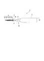
図1に示すように、本発明の第一実施形態の歯間ブラシ1は、先端側に向けて徐々に縮径する硬質樹脂(第一の合成樹脂)により構成される把持部2と、把持部2の先端から延びるブラシ部3と、を備える。
図2に示すように、ブラシ部3は、把持部2の先端から延びる軸材4と、軸材4から突設されたブラシ材を形成する複数の突出片5a〜5d(5)と、を備える。
図3に示すように、軸材4は、把持部2の先端から延びる硬質樹脂(第一の合成樹脂)を主材とする芯部4aと、芯部4aを被覆する軟質樹脂(第二の合成樹脂)からなる被覆部4bと、を備える。軸材4の軸線からみて放射状に突出している突出片5は、軟質樹脂からなり、被覆部4bと一体的に形成されている。Hereinafter, an example of the interdental brush according to the first aspect of the present invention will be described in detail with reference to the drawings.
As shown in FIG. 1, the
As shown in FIG. 2, the
As shown in FIG. 3, the
<把持部>
把持部2は、指で把持するための部材である。本実施形態の把持部2の形状は、指で把持できる形状であれば特に限定されず、例えば、板状、円柱状、三角柱状、四角柱状等の柱状が挙げられる。
把持部2を指で持ち易くする目的で、例えば、把持部2に凹凸、穴、貫通孔、湾曲等が形成されていてもよい。<Grip part>
The
In order to make it easy to hold the
把持部2には、先端側に向かうにつれて縮径する縮径部2aが形成され、縮径部2aの先端にブラシ部3が設けられている。
縮径部2aが設けられていると、鏡で確認しながら歯間ブラシ1を使用する際に、歯間中におけるブラシ部3の状態を視認し易くなる。さらに、縮径部2aが手元に向けて徐々に拡径しているため、歯間への挿入が縮径部2aで止まり易く、歯間ブラシ1を過度に挿入することを防止できる。The
When the reduced
縮径部2aの最小直径〜最大直径の範囲は特に限定されず、例えば1mm〜5mmが好ましく、1.5mm〜5mmがより好ましく、1.5mm〜4mmがさらに好ましい。
上記最小直径が上記範囲の下限値以上であると構造的強度を高められる。
上記最大直径が上記範囲の上限値以下であると口内における取り扱いが容易になる。
縮径部2aの直径は、縮径方向(ブラシ部の長手方向)に直交する断面の直径である。その断面が円形ではない場合、例えば、矩形、楕円形、その他の多角形である場合、その断面形状を含む最小円の直径を縮径部2aの直径とする。The range of the minimum diameter to the maximum diameter of the reduced
When the minimum diameter is not less than the lower limit of the above range, the structural strength can be increased.
When the maximum diameter is not more than the upper limit of the above range, handling in the mouth becomes easy.
The diameter of the reduced
図1の例において、縮径部2aの最小直径は、符号「3a」が指す位置の直径である。前記位置は、ブラシ部3と縮径部2aの境界である。ここで、符号「3a」を便宜的にブラシ部3の基端を示す符号として使用する。また、縮径部2aの最大直径は、把持部2の直径R1と同じである。なお、縮径部2aの最小直径及び最大直径には、軟質樹脂層6の厚さは含まれない。 In the example of FIG. 1, the minimum diameter of the reduced
把持部2の幅又は直径(太さ)R1は特に限定されず、例えば5mm〜10mmが好ましい。
上記幅又は直径が上記範囲の下限値以上であると構造的強度を高められる。
上記幅又は直径が上記範囲の上限値以下であると口内清掃時の取り扱いが容易になる。The width or diameter (thickness) R1 of the
If the width or diameter is equal to or greater than the lower limit of the above range, the structural strength can be increased.
When the width or diameter is not more than the upper limit of the above range, handling during mouth cleaning becomes easy.
把持部2の構成材料は特に限定されず、従来の歯間ブラシの把持部を構成する公知の材料が適用できる。把持部2の構成材料は合成樹脂であることが好ましく、把持部2の先端から延びる軸材4との一体性を高める観点から、後で詳述する軸材4の芯部4aの構成材料と同じであることが好ましい。本実施形態においては、把持部と軸材とが一体に形成されていることが好ましい。
把持部2の構成材料は、1種でもよく、2種以上が含まれる複合材料でもよい。The constituent material of the holding
The constituent material of the
<ブラシ部>
図2に示すように、ブラシ部3は、把持部2の縮径部2aの先端(ブラシ部3の基端3a)から延びる軸材4を備える。種々の長さの複数の第一突出片5a〜第四突出片5dは、軸材4の軸線に対して直交する放射状に突設されている。各突出片は、軸材4の被覆部4bをなす軟質樹脂の一部が、芯部4a上の被覆部4bの表面から突出して形成されている。<Brush part>
As shown in FIG. 2, the
軸材4を被覆する軟質樹脂は、ブラシ部3の基端3aから縮径部2aの上に延設され、縮径部2aの一部を被覆する軟質樹脂層6を形成している。 The soft resin that covers the
軸材4の形状は、複数の突出片5が設置可能であり、歯間に挿入可能な形状であれば特に限定されず、例えば、円柱状、三角柱状、四角柱状等の柱状の他、板状等の形状が挙げられる。
本実施形態の例では、軸材4の形状は、先端に向かうにつれて縮径する円柱状(すなわち、円錐台)である。これにより、ブラシ部3を歯間に挿入することがより容易になる。The shape of the
In the example of the present embodiment, the shape of the
軸材4の長さは、10mm以上が好ましく、歯間の清掃効率を高めるために、12mm以上がより好ましく、13mm以上がさらに好ましい。
軸材4の長さの上限は特に限定されず、例えば20mm以下であると、口内における操作性が高まるので好ましい。よって、軸材4の長さは10〜20mmが好ましく、12〜20mmがより好ましく、13〜20mmがさらに好ましい。The length of the
The upper limit of the length of the
軸材4の太さは特に限定されず、例えば、軸材4の先端から0.1mmの部位の長手方向に直交する断面の面積が、好ましくは0.010mm2〜1.500mm2、より好ましくは0.030mm2〜1.200mm2、さらに好ましくは0.060mm2〜0.800mm2、となるような太さが好ましい。また、軸材4の基端部分の長手方向に直交する断面の面積が、好ましくは0.200mm2〜3.140mm2、より好ましくは0.380mm2〜2.540mm2、さらに好ましくは0.500mm2〜1.770mm2、となるような太さが好ましい。
上記断面の面積が上記の下限値以上であると、軸材4の剛性をより高められる。
上記断面の面積が上記の上限値以下であると、軸材4を狭い歯間への挿入することが一層容易になり、清掃力を高められる。The thickness of the
When the area of the cross section is not less than the above lower limit value, the rigidity of the
When the area of the cross section is not more than the above upper limit value, the
軸材4の基端から先端へ向かう太さは一定でもよく、先端に向かうにつれて縮径する又は拡径するテーパー形状であってもよい。テーパー形状である場合、軸材4の軸線に対する軸材4の表面がなす角度(テーパー角度)は、特に限定されず、一定であってもよく、漸次又は段階的に変化してもよい。 The thickness of the
[軸材の強度]
歯間ブラシ1の軸材4は、下記(A)〜(C)を満たす。
(A)軸しなり強度;把持部2を固定し、軸材4の先端から5mmの部分を10mm/secの速度で弾いたときの反発力が0.56N以上である。
(B)軸折れ強度;ブラシ部3の基端部分を、前記軸材の軸線に対して直交する第一方向に90度折り曲げ、元に戻し、第一方向と反対の第二方向に90度折り曲げ、元に戻す、という左右折り曲げ試験において、芯部4aが破断するまでの同一方向への折り曲げ回数が20回以上である。
(C)繰り返し曲げ強度;ブラシ部3の基端部分を、前記軸材の軸線に対して直交する第一方向に90度折り曲げ、元に戻す、という90度折り曲げ試験において、同一方向へ5回目に折り曲げる際の最大応力が1.7N以上である。[Strength of shaft material]
The
(A) Shaft bending strength: The repulsive force when the
(B) Axial bending strength; the proximal end portion of the
(C) Repeated bending strength; in the 90-degree bending test in which the proximal end portion of the
(A)軸しなり強度は、以下の試験で測定される。
歯間ブラシ1の把持部2の中央を任意の手段、例えば治具で固定し、歯間ブラシ1のブラシ部3の先端から5mmの部分に、10mm/secで移動する摩擦子を摺動させ、弾いたときの抵抗値(単位:N)をISO 8627法(歯ブラシの硬さ規格)に用いる装置を使用して測定する。この際、前記摩刷子がブラシ部3の先端から5mmの位置よりも把持部2側の領域に当たらない様に測定する。(A) The axial bending strength is measured by the following test.
The center of the
(B)軸折れ強度は、以下の左右折り曲げ試験により測定される。
まず、歯間ブラシ1のブラシ部3の基端3aを除くブラシ部3全体を任意の手段、例えば治具で固定し、その固定部から5mmの間隔を空けて、把持部2側をチャックで挟持した。これにより、治具とチャックとの間に5mmの未固定領域(露出領域)が存在する。
この未固定領域は、ブラシ部3の基端3aを含む部分(ブラシ部3の基端部分)である。ここで、ブラシ部3の基端3aは、ブラシ部3に設けられた把持部2側に最も近い突出片5の把持部2側の裾、すなわち列設された突出片5の生え際、とする。
このブラシ部3の基端部分を、軸材4の軸線に対して直交する第一方向に90度折り曲げ、元に戻す。(すなわち、基端部分でブラシ部3を90度折り曲げ、元に戻す。)ここで、第一方向は軸材4が延びる軸線方向に見て、例えば図3の紙面奥行き方向に見て、左方向とすることができる。
続いて、前記基端部分を、第一方向とは反対の第二方向に90度折り曲げ、元に戻す。
ここで、第二方向は、第一方向とは真逆の方向で、軸材4の軸線に対して直交する方向であり、例えば図3の紙面奥行き方向(軸線方向)に見て、右方向とすることができる。この左右一組の折り曲げを、本試験における1回の折り曲げ回数としてカウントする。(B) The axial bending strength is measured by the following left and right bending test.
First, the
This unfixed region is a portion including the
The base end portion of the
Subsequently, the base end portion is bent 90 degrees in a second direction opposite to the first direction and returned to its original state.
Here, the second direction is a direction opposite to the first direction, and is a direction orthogonal to the axis of the
上記の左右一組の折り曲げを同一方向へ(同じ第一方向と第二方向へ)、30rpm(毎分30回の速度)で繰り返して、軸材4の芯部4aが破断するまでの回数を調べる。軸材4の芯部4aが破断したことは、目視で判断する。軸材4の芯部4aが破断した後で、被覆部4bによってブラシ部3の折れた先端側と基端側(把持部2側)とが依然としてつながっている場合がある。この場合、折り曲げに必要な力が極端に低下することで、破断したことが分かる。また、被覆部4bを剥いで芯部4aが破断したことを目視で確認することによって、上記判断が正しかったことを追認できる。
なお、20回目の折り曲げが終了する前に、20回目の折り曲げ中に破断した歯間ブラシについては、20回未満で破断したとする。The number of times until the
It is assumed that the interdental brush that broke during the 20th folding before the 20th folding is broken is broken less than 20 times.
(C)繰り返し曲げ強度は、以下の90度折り曲げ試験により測定される。
まず、歯間ブラシ1の把持部2の中央を任意の手段、例えば治具で固定し、歯間ブラシ1のブラシ部3の基端3aに押し具を当てる。ここで、ブラシ部3の基端3aの位置は、(B)軸折れ強度の場合と同じ位置である。続いて、押し具によってブラシ部3の基端3aから先端側を軸材4の軸線に対して直交する第一方向に90度折り曲げ、元に戻す。ここで、第一方向は軸材4が延びる軸線方向に見て、例えば図3の紙面奥行き方向に見て、左方向とすることができる。この90度の折り曲げを、本試験における1回の折り曲げ回数としてカウントする。
上記の左右折り曲げを同一方向へ(同じ第一方向へ)4回繰り返して、同一方向へ5回目に折り曲げる際の最大応力をプッシュプルゲージによって測定する。各回の折り曲げは、80mm/secの押し付け速度で行う。プッシュプルゲージは、例えばイマダ社製の普及型デジタルフォースゲージD2Dを使用して行う。(C) The repeated bending strength is measured by the following 90-degree bending test.
First, the center of the
The above left and right bending is repeated four times in the same direction (in the same first direction), and the maximum stress when bending the fifth time in the same direction is measured with a push-pull gauge. Each folding is performed at a pressing speed of 80 mm / sec. The push-pull gauge is performed using, for example, a popular digital force gauge D2D manufactured by Imada Corporation.
(A)軸しなり強度は、0.56N以上であり、好ましくは0.60N以上、より好ましくは0.65N以上、さらに好ましくは0.70N以上である。
上記下限値以上であると、歯間ブラシ1のブラシ部3が適度な剛性を有するため、歯間に対する挿入及び抜去を容易に行うことができる。上限値は特に限定されず、例えば、1.00N以下が挙げられる。よって、上記軸しなり強度は、例えば、0.56〜1.00Nが好ましく、0.60〜1.00Nがより好ましく、0.65〜1.00Nがさらに好ましく、0.70〜1.00Nが特に好ましい。
上記軸しなり強度は、軸材4を構成する合成樹脂の種類、繊維材の種類及び量、軸材4の基端(ブラシ部3の基端3a)の太さ等の組み合わせにより調節される。(A) The axial bending strength is 0.56 N or more, preferably 0.60 N or more, more preferably 0.65 N or more, and further preferably 0.70 N or more.
Since the
The shaft bending strength is adjusted by a combination of the type of synthetic resin constituting the
(B)軸折れ強度は、20回以上であり、好ましくは100回以上、より好ましくは150回以上、さらに好ましくは200回以上である。
上記下限値以上であると、使用時やブラシの洗浄時にブラシ部3が一時的に屈曲された場合にも、破断し難く、耐久性に優れる。上限値は特に限定されないが、例えば1万回未満が適当である。
上記軸折れ強度は、軸材4を構成する合成樹脂の種類、繊維材の種類及び量、軸材4の基端(ブラシ部3の基端3a)の太さ等の組み合わせにより調節される。(B) The axial bending strength is 20 times or more, preferably 100 times or more, more preferably 150 times or more, and further preferably 200 times or more.
When it is at least the above lower limit, even when the
The shaft bending strength is adjusted by a combination of the type of synthetic resin constituting the
(C)繰り返し曲げ強度は、1.70N以上であり、好ましくは1.75N以上、より好ましくは1.80N以上、さらに好ましくは1.85N以上である。
上記下限値以上であると、使用時やブラシの洗浄時にブラシ部3が屈曲した後、元の状態に戻して、再度使用することが可能であり、耐久性に優れる。上限値は特に限定されず、例えば、2.50N以下が挙げられる。よって、上記繰り返し曲げ強度は、例えば、1.70〜2.50Nが好ましく、1.75〜2.50Nがより好ましく、1.80〜2.50Nがさらに好ましく、1.85〜2.50Nが特に好ましい。
上記繰り返し曲げ強度は、軸材4を構成する合成樹脂の種類、繊維材の種類及び量、軸材4の基端(ブラシ部3の基端3a)の太さ等の組み合わせにより調節される。(C) The repeated bending strength is 1.70 N or more, preferably 1.75 N or more, more preferably 1.80 N or more, and further preferably 1.85 N or more.
If it is at least the above lower limit value, it is possible to return to the original state after the
The repeated bending strength is adjusted by a combination of the type of synthetic resin constituting the
[軸材の芯部]
軸材4の芯部4aの構成材料は特に限定されず、上記(A)〜(C)の強度を実現する観点から、合成樹脂を主材として含むことが好ましい。
前記合成樹脂は、硬質樹脂及び軟質樹脂の少なくとも何れか一方であることが好ましく、硬質樹脂であることがより好ましい。[Core of shaft]
The constituent material of the
The synthetic resin is preferably at least one of a hard resin and a soft resin, and more preferably a hard resin.
軸材4の芯部4aの全質量に対して、前記合成樹脂の含有量は50〜100質量%が好ましく、60〜100質量%がより好ましく、70〜100質量%がさらに好ましい。
軸材4の芯部4aの全質量に対して、前記硬質樹脂の含有量は50〜100質量%が好ましく、60〜100質量%がより好ましく、70〜100質量%がさらに好ましい。
前記合成樹脂は1種類であってもよく、2種類以上であってもよい。50-100 mass% is preferable, as for content of the said synthetic resin with respect to the total mass of the
50-100 mass% is preferable with respect to the total mass of the
The synthetic resin may be one type or two or more types.
前記硬質樹脂の種類は特に限定されず、公知の硬質樹脂が適用可能であり、例えば、曲げ弾性率(JIS K7203)が500〜3000MPaの範囲とされた樹脂を用いることができる。
このような硬質樹脂としては、例えば、ポリプロピレン(PP)、ポリトリメチレンテレフタレート(PTT)、ポリエチレンテレフタレート(PET)、ポリブチレンテレフタレート(PBT)、ポリシクロへキシレンジメチレンテレフタレート(PCT)、ポリアセタール(POM)、ポリスチレン(PS)、アクリロニトリル・ブタジエン・スチレン樹脂(ABS)、セルロースプロピオネート(CP)、ポリアリレート、ポリカーボネート、アクリロニトリル・スチレン共重合樹脂(AS)等が挙げられる。これらの中でも、被覆部4bを構成する軟質樹脂との接着性が良好なポリエステルが好ましく、PTT、PBTがより好ましい。The kind of said hard resin is not specifically limited, A well-known hard resin is applicable, For example, resin whose bending elastic modulus (JIS K7203) was made into the range of 500-3000 MPa can be used.
Examples of such hard resins include polypropylene (PP), polytrimethylene terephthalate (PTT), polyethylene terephthalate (PET), polybutylene terephthalate (PBT), polycyclohexylene dimethylene terephthalate (PCT), and polyacetal (POM). , Polystyrene (PS), acrylonitrile / butadiene / styrene resin (ABS), cellulose propionate (CP), polyarylate, polycarbonate, acrylonitrile / styrene copolymer resin (AS), and the like. Among these, polyester having good adhesiveness with the soft resin constituting the covering
軸材4の芯部4aの構成材料には、前記主材として使用される合成樹脂以外の任意成分を添加してもよい。好適な任意成分として、例えば、無機材料及び/又は有機材料からなるフィラーが挙げられる。フィラーを芯部4aの構成材料として前記合成樹脂に添加することによって、芯部4aの上記(A)〜(C)の強度を向上させることができる。 Arbitrary components other than the synthetic resin used as the main material may be added to the constituent material of the core 4a of the
前記フィラーの構成材料は特に限定されず、例えば、ガラス、セラミックス、鉱物、炭素材料等の無機材料、合成樹脂等の有機材料、等が挙げられる。
フィラーを構成する合成樹脂は、軸材4の芯部4aを構成する合成樹脂と同じであってもよく、異なっていてもよい。好適な合成樹脂として、例えば、アラミド、ナイロン等のポリアミドが挙げられる。
フィラーを構成する炭素材料として、例えば、カーボンブラック等の炭素粒子、カーボンナノチューブ、フラーレン、グラフェン等が挙げられる。
フィラーを構成する鉱物及びセラミックスとして、例えば、マイカ、タルク、炭化ケイ素、チタン酸化合物等が挙げられる。The constituent material of the filler is not particularly limited, and examples thereof include inorganic materials such as glass, ceramics, minerals, and carbon materials, and organic materials such as synthetic resins.
The synthetic resin constituting the filler may be the same as or different from the synthetic resin constituting the
Examples of the carbon material constituting the filler include carbon particles such as carbon black, carbon nanotubes, fullerene, and graphene.
Examples of minerals and ceramics constituting the filler include mica, talc, silicon carbide, titanate compounds and the like.
前記フィラーの形状は特に限定されず、繊維状、粒子状、板状等のいずれの形状でもよく、上記(A)〜(C)の強度を容易に向上できることから、繊維状が好ましい。 The shape of the filler is not particularly limited, and may be any shape such as a fiber shape, a particle shape, and a plate shape, and the fiber shape is preferable because the strengths (A) to (C) can be easily improved.
繊維状フィラーの繊維長は特に限定されず、例えば、3μm〜300μmが好ましく、6μm〜100μmがより好ましく、9μm〜50μmがさらに好ましい。
繊維長が上記下限値以上であると、軸材4の芯部4aの剛性をより高めることができる。
繊維長が上記上限値以下であると、軸材4の芯部4aの靱性をより高めることができる。
ここで、上記繊維長は、前記繊維状フィラー100個の繊維長(繊維の長手方向における先端から後端までの長さ)の算術平均である。よって、上記繊維長は平均繊維長と読み換えられる。繊維状フィラーの繊維長は電子顕微鏡観察によって計測される。The fiber length of a fibrous filler is not specifically limited, For example, 3 micrometers-300 micrometers are preferable, 6 micrometers-100 micrometers are more preferable, 9 micrometers-50 micrometers are more preferable.
When the fiber length is equal to or greater than the lower limit, the rigidity of the
When the fiber length is not more than the above upper limit, the toughness of the
Here, the fiber length is an arithmetic average of the fiber lengths of 100 fibrous fillers (length from the front end to the rear end in the longitudinal direction of the fibers). Therefore, the fiber length can be read as the average fiber length. The fiber length of the fibrous filler is measured by observation with an electron microscope.
繊維状フィラーの繊維径は特に限定されず、例えば、0.1μm〜2.0μmが好ましく、0.2μm〜1.0μmがより好ましく、0.3μm〜0.8μmがさらに好ましい。
繊維径が上記下限値以上であると、軸材4の芯部4aの剛性をより高めることができる。
繊維径が上記上限値以下であると、軸材4の芯部4aの靱性をより高めることができる。
ここで、上記繊維径は、前記繊維状フィラー100個の繊維径(繊維の長手方向に直交する方向における最長の長さ)の算術平均である。よって、上記繊維径は平均繊維径と読み換えられる。繊維状フィラーの繊維径は電子顕微鏡観察によって計測される。The fiber diameter of a fibrous filler is not specifically limited, For example, 0.1 micrometer-2.0 micrometers are preferable, 0.2 micrometer-1.0 micrometer are more preferable, 0.3 micrometer-0.8 micrometer are further more preferable.
The rigidity of the
When the fiber diameter is not more than the above upper limit, the toughness of the
Here, the fiber diameter is an arithmetic average of the fiber diameters of 100 fibrous fillers (the longest length in the direction orthogonal to the longitudinal direction of the fibers). Therefore, the fiber diameter can be read as the average fiber diameter. The fiber diameter of the fibrous filler is measured by observation with an electron microscope.
軸材4の芯部4aの全質量に対する前記フィラーの含有量は特に限定されず、例えば、5〜29質量%が好ましく、10〜25質量%がより好ましく、15〜20質量%がさらに好ましい。
上記含有量が上記下限値以上であると、軸材4の芯部4aの剛性をより高められる。
上記含有量が上記上限値以下であると、軸材4の芯部4aの靱性をより高められる。Content of the said filler with respect to the total mass of the
The rigidity of the
When the content is not more than the upper limit, the toughness of the
軸材4の芯部4aには、前記主材としての合成樹脂とともに、任意成分のフィラーとして、繊維長3μm〜300μm且つ繊維径0.1μm〜2.0μmである繊維材が含有されることが好ましい。 The core 4a of the
前記繊維材としては、化学式K2Ti8O17又はK2Ti6O13で表されるチタン酸カリウム繊維が特に好適である。このようなチタン酸カリウム繊維は市販されており、例えば、大塚化学社製のティスモ(TISMO)(登録商標)が挙げられる。As the fiber material, potassium titanate fiber represented by the chemical formula K2 Ti8 O17 or K2 Ti6 O13 is particularly suitable. Such potassium titanate fibers are commercially available, and examples thereof include TISMO (registered trademark) manufactured by Otsuka Chemical Co., Ltd.
芯部4aの構成材料のASTM D790(3点荷重、A法)に準拠して測定される曲げ弾性率は、上記(A)〜(C)の強度を実現する観点から、3.0GPa以上が好ましく、4.0GPa以上がより好ましく、5.0GPa以上が更に好ましい。その上限値は特に限定されず、例えば20GPa以下が適当である。 The bending elastic modulus measured in accordance with ASTM D790 (3-point load, method A) of the constituent material of the
芯部4aの構成材料のASTM D638に準拠して測定される引張破断伸びは、上記(A)〜(C)の強度を実現する観点から、7.0%以上が好ましく、8.0%以上がより好ましく、10.0%以上が更に好ましい。その上限値は特に限定されず、例えば30%以下が適当である。 From the viewpoint of realizing the above strengths (A) to (C), the tensile elongation at break measured in accordance with ASTM D638 of the constituent material of the
芯部4aの構成材料の曲げ弾性率と引張破断伸びの好適な組み合わせとして、上記に例示した好適な範囲の任意の組み合わせが挙げられる。具体的には、例えば、(曲げ弾性率の数値)且つ(引張破断伸びの数値)の書式で表すと、3.0GPa以上且つ7.0%以上、3.0GPa以上且つ8.0%以上、3.0GPa以上且つ10.0%以上、4.0GPa以上且つ7.0%以上、4.0GPa以上且つ8.0%以上、4.0GPa以上且つ10.0%以上、5.0GPa以上且つ7.0%以上、5.0GPa以上且つ8.0%以上、5.0GPa以上且つ10.0%以上の組み合わせが挙げられる。これらのなかでも、曲げ弾性率3.0GPa以上且つ引張破断伸び7.0%以上である構成材料を使用すると、上記(A)〜(C)の強度を容易に実現することができる。 As a suitable combination of the bending elastic modulus of the constituent material of the
芯部4aの構成材料は、上記(A)〜(C)の強度をより容易に実現する観点から、フィラー及び合成樹脂を含む複合材料であることが好ましい。 The constituent material of the
[軸材の被覆部]
軸材4の被覆部4bの構成材料は特に限定されず、軟質樹脂が好適である。被覆部4bが軟質樹脂で成形されていると、ブラシ部3を歯間に挿入する際に歯肉や歯を傷つけにくく、当たり心地がより良好になる。
被覆部4bを構成する軟質樹脂のショア硬度A(ショアA硬さ)は、A90以下が好ましく、A30〜A80がより好ましい。好適な軟質樹脂として、例えば、ポリオレフィン系エラストマー、スチレン系エラストマー、ポリエステル系エラストマー等の公知のエラストマー樹脂が挙げられる。
被覆部4bを構成する軟質樹脂は1種類であってもよく、2種類以上であってもよい。
被覆部4bは、ブラシ部3の全部を覆っていてもよいし、一部のみを覆っていてもよい。[Coating part of shaft material]
The constituent material of the covering
As for the Shore hardness A (Shore A hardness) of the soft resin which comprises the coating |
There may be one kind of soft resin which comprises the coating |
The covering
被覆部4bの厚さは特に限定されず、例えば、0.1mm〜1.0mmが好ましく、0.1mm〜0.5mmがより好ましく、0.1mm〜0.3mmがさらに好ましい。
被覆部4bの厚さが下限値以上であると、突出片5が被覆部4bから脱落することを防止し、ブラシ部3の構造的強度を高めることができる。
被覆部4bの厚さが上限値以下であると、ブラシ部3の全体の直径が太くなり過ぎることを抑制し、狭い歯間への挿入性を高めることができる。
被覆部4bの厚さの測定方法としては、例えば、ブラシ部3において、隣接した2つの突出片5の間を任意に3箇所以上選び、各箇所の軟質樹脂の厚さを顕微鏡や拡大鏡で測定した値の算術平均として求める方法が挙げられる。The thickness of the coating |
When the thickness of the covering
When the thickness of the covering
As a method for measuring the thickness of the covering
[突出片]
軸材4が延びる軸線方向から見て、軸材4から放射状に突出している突出片5の形状や大きさは特に限定されない。本実施形態の歯間ブラシ1のブラシ部3には、図2に示す様に、軸材4の表面からの高さが互いに異なる第一突出片5a〜第四突出片5dが複数設けられている。これらの突出片5は、歯間の清掃を担い、歯垢を掻き取るブラシ(刷毛)材として機能する。[Projection piece]
The shape and size of the protruding
突出片5の高さは特に限定されず、例えば、0.1mm〜2.5mmが好ましく、0.3mm〜1.8mmがより好ましく、0.6mm〜1.2mmがさらに好ましい。ここで、突出片5の高さは、被覆部4bの表面側の基端から先端までの長さを意味する。
突出片5の高さが下限値以上であると、高い刷掃力が得られやすい。
突出片5の高さが上限値以下であると、ブラシ部3を歯間に挿入しやすくなる。
複数の突出片5の相対的な高さは特に限定されず、互いに同じであってもよく、異なっていてもよい。The height of the
When the height of the protruding
It becomes easy to insert the
The relative heights of the plurality of protruding
突出片5の厚さ(太さ)は特に限定されず、例えば、0.1mm〜1.5mmが好ましく、0.1mm〜0.5mmがより好ましく、0.1mm〜0.2mmがさらに好ましい。ここで、突出片5の厚さは、突出片5が突出している方向に対して直交する断面の最大径を意味する。
突出片5の厚さが下限値以上であると、射出成形によって容易に成形することができるとともに、歯垢を掻き取るために必要な剛性が得られ易い。
突出片5の厚さが上限値以下であると、ブラシ部3を歯間に挿入しやすくなる。
複数の突出片5の相対的な厚さは特に限定されず、互いに同じであってもよく、異なっていてもよい。The thickness (thickness) of the
When the thickness of the protruding
It becomes easy to insert the
The relative thickness of the plurality of protruding
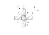
図3に示す歯間ブラシ1において、突出片5は、軸材4の軸周りに90°の等間隔で4方向に放射状に突出して設けられている。
軸材4の延在方向から見て放射状に突出している突出片5の数は特に限定されず、例えば、2〜6つが軸周りに等間隔で放射状に突出していることが好ましい。In the
The number of protruding
軸材4の延在方向から見た突出片5の正面視形状は特に限定されず、例えば、図3に示すように、軸材4からの高さ方向が幅方向よりも長い長方形で、かつその先端側の両方の角部が丸みを帯びた形状が挙げられる。この他の上記正面視形状としては、例えば、台形状、正方形状、長方形状、先端に向かうにつれて幅が狭くなる略楕円状等の形状が挙げられる。 The front view shape of the protruding
ブラシ部3を構成する軸材4が延びる軸方向に見て、互いに隣接する突出片5同士の距離は特に限定されず、例えば、0.3mm〜0.8mmが好ましい。
前記距離が下限値以上であると、各突出片5が独立して機能することが容易になる。
前記距離が上限値以下であると、各突出片の間に歯垢を保持しやすくなり、高い刷掃力が得られやすい。The distance between the projecting
When the distance is equal to or greater than the lower limit value, it becomes easy for each
When the distance is less than or equal to the upper limit value, plaque is easily held between the protruding pieces, and a high brushing force is easily obtained.
ブラシ部3において軸材4が延びる軸方向に列設される突出片5の合計数は特に限定されず、例えば、10〜100個が好ましく、20〜50個がより好ましい。
上記合計数が下限値以上であると、充分な刷掃力が得られやすい。
上記合計数が上限値以下であると、歯間への挿入と抜去の両方が容易になり、歯間を清掃する作業性が高まる。The total number of protruding
When the total number is equal to or greater than the lower limit, a sufficient brushing force can be easily obtained.
When the total number is less than or equal to the upper limit value, both insertion and extraction between teeth are facilitated, and workability for cleaning between the teeth is enhanced.
<製造方法>
本発明の歯間ブラシの製造方法は特に限定されず、公知の製造方法を適用できる。例えば、金型を用いた射出成形により、まず、軸材4の芯部4aと把持部2とを一体的に成形した一次品(基体)10を得る(図4参照)。続いて、芯部4aと縮径部2aの一部を軟質樹脂で被覆し、被覆部4bと突出片5とを一体的に成形したブラシ部3を形成するとともに、縮径部2aの一部を軟質樹脂層6で被覆する(図1参照)。このような公知の射出成形によって歯間ブラシ1を製造することができる。<Manufacturing method>
The manufacturing method of the interdental brush of this invention is not specifically limited, A well-known manufacturing method is applicable. For example, by primary injection molding using a mold, first, a primary product (base body) 10 in which the
軸材4を構成する複合材料の調製において、合成樹脂にフィラー等の任意成分を混合する場合、その混合方法は特に限定されず、例えば、撹拌子、スターラー、ボールミル、自公転ミキサー、超音波分散機等を使用する公知方法が適用される。 In the preparation of the composite material constituting the
<作用効果>
本発明の歯間ブラシは、ブラシ部を構成する軸材が前述した(A)〜(C)を満たすので、耐久性に優れ、使用中に折れることが抑制されるとともに、洗浄して繰り返し使用することができる。
本発明の歯間ブラシは、少なくともブラシ部が合成樹脂製であるので、金属製ワイヤを備える従来の歯間ブラシに比べて歯肉等に当たった場合にも痛みを感じにくく、当たり心地が良好である。<Effect>
The interdental brush of the present invention is excellent in durability because the shaft material constituting the brush portion satisfies the above-mentioned (A) to (C), and is prevented from being broken during use, and is washed and used repeatedly. can do.
Since the interdental brush of the present invention has at least the brush part made of synthetic resin, it is less likely to feel pain when hitting gingiva etc. compared to a conventional interdental brush having a metal wire, and the contact comfort is good. is there.
<他の実施形態>
本発明の歯間ブラシは、前述した第一実施形態の歯間ブラシ1に限定されない。
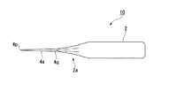
例えば、図5に示すように、軸材4の先端部4cを球状にした歯間ブラシが挙げられる。前記歯間ブラシによれば、軸材4の先端部4cが歯肉に当たった場合の痛みが一層軽減され、より快適な当たり心地が得られる。球状の先端部4cは軟質樹脂で形成されていることが好ましい。<Other embodiments>
The interdental brush of this invention is not limited to the
For example, as shown in FIG. 5, the interdental brush which made the front-end | tip
《第二態様》
本発明の第二態様の歯間ブラシは、把持部と、前記把持部の先端に設けられたブラシ部とを備える合成樹脂製の歯間ブラシである。以下、本発明の歯間ブラシの一例を、図面を参照して詳細に説明する。
第二態様の歯間ブラシの形状は、第一態様の歯間ブラシの説明で用いた図1〜5を参照して説明できる。このため、以下の説明では、図1〜図6を参照して、第一態様と共通する部材には同じ符号を付けている。
第二態様の歯間ブラシ1は、合成樹脂製であり、図1に示すように、把持部2と、把持部2の先端に設けられたブラシ部3とを備える。<< Second aspect >>
The interdental brush according to the second aspect of the present invention is an interdental brush made of a synthetic resin including a grip portion and a brush portion provided at the tip of the grip portion. Hereinafter, an example of the interdental brush of the present invention will be described in detail with reference to the drawings.
The shape of the interdental brush of a 2nd aspect can be demonstrated with reference to FIGS. 1-5 used by description of the interdental brush of a 1st aspect. For this reason, in the following description, the same code | symbol is attached | subjected to the member which is common with a 1st aspect with reference to FIGS.
The
(把持部)
把持部2は、指で把持するための柱状の部材である。
把持部2の形状は、この例では、扁平な板状になっている。
なお、把持部2の形状は、指で把持できる形状であればよく、前記の扁平な板状以外に、円柱状、(三角柱状、四角柱状等)等を採用してもよい。(Gripping part)
The
In this example, the
In addition, the shape of the holding | gripping
この例の把持部2には、ブラシ部3寄りに、先端から後端に向かうにつれて拡径する拡径部2aが設けられている。これにより、ブラシ部3を歯間に挿入した状態で、歯間ブラシ1を誤って軸方向に強く押した場合でも、歯間への挿入が拡径部2aで止まるため、歯間ブラシ1によって口腔内を傷つけることが抑制されやすい。 The
把持部2を形成する材料としては、特に限定されず、歯間ブラシの把持部を形成する公知の材料を使用でき、例えば、後述する軸材4で挙げる材料と同じものが挙げられる。
把持部2を形成する材料は、1種でもよく、2種以上でもよい。It does not specifically limit as a material which forms the holding
The material forming the
(ブラシ部)
ブラシ部3は、把持部2の先端から延びる軸材4と、軸材4から突出している第1突出片5a〜第4突出片5dと、を備える。第1突出片5a〜第4突出片5dは、後述する軸材4の被覆部4bと一体に形成されている。(Brush part)
The
軸材4は、把持部2の先端から延びる柱状の部材である。軸材4としては、円柱状であっても、三角柱状、四角柱状等を採用してもよい。また、軸材4は、先端に向かうにつれて縮径していてもよく、例えば円錐台を形成していてもよい。これにより、ブラシ部3を歯間に挿入することがより容易になる。
図3に示すように、軸材4は、把持部2の先端から延びる芯部4aと、芯部4aの表面を被覆する被覆部4bとを備える。The
As shown in FIG. 3, the
軸材4を形成する材料としては、硬質樹脂が好ましく、そのなかでもJIS K7203に準拠して測定される曲げ弾性率が500〜3000MPaである樹脂が好ましい。具体例は前述と同様である。 As a material for forming the
被覆部4bを形成する材料としては、軟質樹脂が好ましい。被覆部4bを軟質樹脂で形成することで、ブラシ部3を歯間に挿入する際に歯肉等をより傷つけにくくなり、当たり心地がより良好になる。
軟質樹脂としては、例えば、ポリオレフィン系エラストマー、スチレン系エラストマー、ポリエステル系エラストマー等のエラストマー樹脂が挙げられる。As a material for forming the covering
Examples of the soft resin include elastomer resins such as polyolefin elastomers, styrene elastomers, and polyester elastomers.
被覆部4bの厚さは、0.1〜0.5mmが好ましく、0.1〜0.3mmがより好ましい。被覆部4bの厚さが下限値以上であれば、突出片の先端まで軟質樹脂を充填しやすい。被覆部4bの厚さが上限値以下であれば、歯間への挿入性を高めることができる。被覆部4bの厚さの測定方法は前述の通りである。 0.1-0.5 mm is preferable and, as for the thickness of the coating |
ブラシ部3は、図6に示すように、領域(B)17よりも後端寄りに形成された領域(A)14と、領域(A)14よりも先端側に形成された領域(B)17とを含んでいる。領域(A)14は、先端側の領域(A1)12と、領域(A1)12よりも後端側の領域(A2)13とを含む。領域(B)17は、先端側の領域(B1)15と、領域(B1)15よりも後端側の領域(B2)16とを含んでいる。このように、ブラシ部3には、先端から後端に向かって、領域(B1)15、領域(B2)16、領域(A1)12及び領域(A2)13がこの順に形成されている。 As shown in FIG. 6, the
[領域(A)]
領域(A)14は、ブラシ部3において、歯間に対する刷掃力の発現に大きく寄与する領域である。
領域(A)14には、任意の高さの複数の第1突出片5aが軸方向に並んでいる。領域(A)14における先端側の領域(A1)12においては、任意の高さの第1突出片5aと、第1突出片5aよりも高さの低い第2突出片5bとが軸方向に交互に並んでいる。後端側の領域(A2)13においては、任意の高さの第1突出片5aのみが軸方向に並んでいる。
領域(A)が領域(A1)と領域(A2)とからなる場合、軸材の軸方向における領域(A1)と領域(A2)の境界は、領域(A2)が最も広くなるように決定されるものとする。具体的には、この例では、領域(A1)12は最も後端側の第2突出片5bから最も先端側の第1突出片5aまでの領域である。領域(A2)13は、最も後端側の第2突出片5bの後端側の隣りに位置する第1突出片5aから最も後端側の第1突出片5aまでの領域である。[Area (A)]
The region (A) 14 is a region that greatly contributes to the development of the brushing force between the teeth in the
In the region (A) 14, a plurality of first projecting
When the region (A) includes the region (A1) and the region (A2), the boundary between the region (A1) and the region (A2) in the axial direction of the shaft is determined so that the region (A2) is the widest. Shall be. Specifically, in this example, the region (A1) 12 is a region from the second projecting
<第1突出片>
第1突出片5aは、歯間に存在する歯垢等を掻き取るための板状の部材である。板状の突出片は、歯垢等を掻き取る効果が高い。<First protruding piece>
The
第1突出片5aは、図3に示すように、第1突出片5a(突出片5)の平面部が軸材4の軸線方向に直交するように、軸材4の延在方向から見て放射状に突出しているように設けられる。図3の例では、軸材4に延在方向から見たときに、軸材4の軸周りに90°間隔で4方向にそれぞれ第1突出片5aが設けられている。すなわち、軸材4に直交する平面内において、x軸方向と、前記x軸方向に直交するy軸方向にそれぞれ突出しているように、4つの第1突出片5aが設けられている。第1突出片5aは、このように軸材4の軸周りに等間隔に設けられていることが好ましい。 As shown in FIG. 3, the first projecting
軸材4の延在方向から見て放射状に突出している第1突出片5aの数は、図3の例では4つであるが、4つには限定されず、3つ以下であってもよく、5つ以上であってもよい。第1突出片5aは、軸材4の延在方向から見たときに、放射状に少なくとも2つ突出していることが好ましい。
軸材4の延在方向から見て放射状に突出している複数の第1突出片5aは、互いに等間隔で形成され、各第1突出片5aの中心線と軸材4の中心を結ぶ線とのなす角が全て等しく形成されていることが好ましい。一方、前記複数の第1突出片5aが、互いに非等間隔で形成され、各第1突出片5aの中心と軸材4の中心を結ぶ線とのなす角が互いに異なるように形成されていても構わない。The number of first projecting
The plurality of first projecting
図3の例の第1突出片5aの正面視形状は、軸材4からの高さ方向が幅方向よりも長い長方形で、かつその先端側の両方の角部が丸みを帯びた形状になっている。なお、第1突出片5aの正面視形状は、本実施形態の形状には限定されず、例えば、台形状、正方形状、長方形状、先端に向かうにつれて幅が狭くなる略楕円状等であってもよい。 The front view shape of the first projecting
第1突出片5aは、ブラシ部3に設けられる突出片のうち、軸材4からの高さが最も高い。領域(A)14に設けられた第1突出片5aにより、高い刷掃力が得られる。
第1突出片5aの高さは、0.7〜1.5mmが好ましく、0.7〜1.2mmがより好ましい。第1突出片5aの高さが下限値以上であれば、高い刷掃力が得られやすい。第1突出片5aの高さが上限値以下であれば、ブラシ部3を歯間に挿入しやすくなる。
ブラシ部3が有する個々の第1突出片5aの高さは全て同じであることが好ましいが、製造上の都合でその高さが不均一になる場合がある。この不均一な程度は、±0.05mm以下であれば許容され、同じ高さであるとみなす。
ブラシ部3に形成された各突出片(突出片5a〜5d)の高さは、顕微鏡や拡大鏡を用いて、軸材4の延在方向(軸線方向)に見て、軸材4からの高さを計測して求められる。The first
The height of the first
The heights of the individual first protruding
The height of each protrusion piece (
第1突出片5aの厚さは、0.1〜0.2mmが好ましく、0.10〜0.15mmがより好ましい。第1突出片5aの厚さが下限値以上であれば、射出成形によって容易に成形することができる。第1突出片5aの厚さが上限値以下であれば、ブラシ部3を歯間に挿入しやすくなる。
ブラシ部3が有する個々の第1突出片5aの厚さは全て同じであることが好ましいが、製造上の都合でその厚さが不均一になる場合がある。この不均一な程度は、±0.05mm以下であれば許容される。
ブラシ部3に形成された各突出片(突出片5a〜5d)の厚さは、顕微鏡や拡大鏡を用いて、各突出片の延在方向(中心線方向)に見て、その方向に直交する断面を含む最小円の直径を計測して求められる。The thickness of the first
The thicknesses of the individual first protruding
The thickness of each protruding piece (projecting
<第2突出片>
第2突出片5bは、歯間に存在する歯垢等を掻き取るための板状の部材であって、軸材4からの高さが第1突出片5aの高さよりも0.1mm以上低いものである。
ブラシ部3が有する個々の第2突出片5bの高さは全て同じであることが好ましいが、製造上の都合でその高さが不均一になる場合がある。この不均一な程度は、±0.05mm以下であれば許容され、同じ高さであるとみなす。
第2突出片5bが軸材4に設けられる態様は、第1突出片5aの場合と同様であり、好ましい態様も同じである。軸材4の延在方向から見て放射状に突出している第2突出片5bの数は、軸材4の延在方向から見て放射状に突出している第1突出片5aの数と同じであってもよく、異なっていてもよい。<Second protruding piece>
The
The heights of the individual second projecting
The aspect in which the
この例の第2突出片5bの正面視形状は、軸材4からの高さが第1突出片5aよりも0.1mm以上低い以外は第1突出片5aと同様であり、矩形の先端側の両方の角部が丸みを帯びた形状になっている。
第2突出片5bの正面視形状は、台形状、正方形状、長方形状、先端に向かうにつれて幅が狭くなる略楕円状等であってもよい。The front-view shape of the second
The front view shape of the second
第2突出片5bの高さは、第1突出片5aの高さよりも0.1mm以上低い範囲で、0.3〜0.7mmが好ましく、0.3〜0.5mmがより好ましい。第2突出片5bの高さが下限値以上であれば、高い刷掃力が得られやすい。第2突出片5bの高さが上限値以下であれば、ブラシ部3を歯間に挿入しやすくなる。 The height of the second
第2突出片5bの厚さは、0.1〜0.2mmが好ましく、0.10〜0.15mmがより好ましい。第2突出片5bの厚さが下限値以上であれば、射出成形によって容易に成形することができる。第2突出片5bの厚さが上限値以下であれば、ブラシ部3を歯間に挿入しやすくなる。 The thickness of the second
<領域(A1)>
領域(A1)12では、第1突出片5aと、第1突出片5aよりも高さの低い第2突出片5bとが軸方向に交互に並んでいることで、歯間に挿入する際に第1突出片5aが倒れても、隣りが高さの低い第2突出片5bであることで第1突出片5a同士の重なりが小さくなる。これにより、領域(A1)12において第1突出片5aが倒れた状態を軸材4の延在方向から見たときの第1突出片5aを含むブラシ部3の外周の太さは、第1突出片5aのみが同じ間隔で並んでいる場合に比べて細くなる。そのため、領域(A1)12が設けられていることで、ブラシ部3を歯間に挿入することが容易になる。
このように、領域(A1)12は、第1突出片5aによって充分な清掃力を有しつつ、歯間への挿入性を高めている。<Area (A1)>
In the region (A1) 12, the first protruding
As described above, the region (A1) 12 has a sufficient cleaning force by the first projecting
図6の例の領域(A1)12では、第1突出片5aと第2突出片5bとを並べる態様は、第1突出片5aと第2突出片5bとが軸方向に交互になっていれば、軸材4の軸回りの並び方は特に限定されない。すなわち、第1突出片5aと第2突出片5bとが軸方向に交互になっていれば、軸材4の軸回りに並ぶ突出片は、全てが第1突出片5a又は第2突出片5bになっていてもよく、第1突出片5aと第2突出片5bとが混在していてもよい。
図3,6の例では、軸材4の軸周りのx軸方向とy軸方向に4つの第1突出片5aが突出している組と、軸材4の軸周りのx軸方向とy軸方向に4つの第2突出片5bが突出している組とが、軸方向に交互に並んでいる。このような態様の他、例えば、軸材4の軸周りのx軸方向に2つの第1突出片5aが突出し、y軸方向に2つの第2突出片5bが突出している組と、軸材4の軸周りのx軸方向に2つの第2突出片5bが突出し、y軸方向に2つの第1突出片5aが突出している組とが、軸方向に交互に並んでいる態様であってもよい。
2つの突出片が軸方向に交互に並んでいる状態とは、軸方向に見て、手前側の突出片が奥側の突出片の少なくとも一部と重なって見える状態をいう。In the area (A1) 12 in the example of FIG. 6, the first protruding
3 and 6, a set in which the four first projecting
The state in which the two protruding pieces are alternately arranged in the axial direction means a state in which the protruding piece on the near side appears to overlap at least a part of the protruding piece on the back side when viewed in the axial direction.
領域(A1)12における隣り合う第1突出片5aと第2突出片5bとの軸方向の距離は、0.3〜0.8mmが好ましく、第2突出片5bの高さと同じ長さであることがより好ましい。前記距離が下限値以上であれば、第1突出片5aと第2突出片5bとの重なりが比較的緩和されて、歯間への挿入性が高まりやすい。前記距離が上限値以下であれば、第1突出片5aと第2突出片5bとの間にプラークを保持しやすくなり、高い刷掃力が得られやすい。 The axial distance between the adjacent first projecting
領域(A1)12において軸方向に並ぶ第1突出片5a及び第2突出片5bの合計数は、図6の例では16個である。前記合計数は、4〜30個が好ましく、10〜20個がより好ましい。第1突出片5a及び第2突出片5bの合計数が上記範囲内であれば、領域(A1)12の挿入性と刷掃力を両立した機能が充分に発揮されやすい。 The total number of the first protruding
<領域(A2)>
領域(A2)13では、第1突出片5aのみが軸方向に並んでいることで、歯垢等を掻き取る力が強く、高い刷掃力が得られる。<Area (A2)>
In the region (A2) 13, since only the first projecting
領域(A2)13における隣り合う第1突出片5a同士の軸方向の距離は、0.3〜1.5mmが好ましく、0.5〜0.8mmがより好ましい。前記距離が下限値以上であれば、第1突出片5a同士の重なりが比較的緩和されて、歯間への挿入性が高まりやすい。前記距離が上限値以下であれば、第1突出片5a同士の間にプラークを保持しやすくなり、高い刷掃力が得られやすい。 The axial distance between adjacent first protruding
領域(A2)13において軸方向に並ぶ第1突出片5aの数は、この例では8個である。
領域(A2)13において軸方向に並ぶ第1突出片5aの数は、3〜30個が好ましく、5〜20個がより好ましい。第1突出片5aの数が上記範囲内であれば、領域(A2)13の高い刷掃力が充分に発揮されやすい。In this example, the number of the first protruding
In the region (A2) 13, the number of the first protruding
本発明では、領域(A)において、前記の任意の高さ(例えば0.5〜2.0mm)の突出片同士の軸方向の距離が、先端に向かって大きくなっていることが好ましい。これにより、領域(A)の先端側が歯間に挿入されやすくなる。
例えば、図6の例では、領域(A1)12における第1突出片5a同士の軸方向の距離が、領域(A2)13における第1突出片5a同士の軸方向の距離よりも0.1mm以上大きくなっている。これにより、ブラシ部3の領域(A)14を歯間に挿入した際に第1突出片5aが倒れても、先端側の領域(A1)12では領域(A2)13に比べて、第1突出片5aが重なりにくい。
そのため、軸材4の延在方向から見たときに、第1突出片5a同士の距離が大きい領域(A1)12の太さが領域(A2)13に比べて細くなり、歯間への挿入性が向上する。In the present invention, in the region (A), it is preferable that the axial distance between the projecting pieces having the arbitrary height (for example, 0.5 to 2.0 mm) increases toward the tip. Thereby, it becomes easy to insert the front end side of a field (A) between teeth.
For example, in the example of FIG. 6, the axial distance between the first protruding
Therefore, when viewed from the extending direction of the
[領域(B)]
領域(B)17は、刷掃力を有するうえ、ブラシ部3を歯間に挿入する際の挿入性の向上に寄与する領域である。
領域(B)17における先端側の領域(B1)15には、軸材4からの高さが第1突出片5aよりも0.1mm以上低い第3突出片5cのみが軸方向に並んでいる。領域(B)17における後端側の領域(B2)16には、軸材4からの高さが第1突出片5aよりも0.1mm以上低い第4突出片5dのみが軸方向に並んでいる。すなわち、領域(B)17には、第1突出片5aよりも高さが0.1mm以上低い突出片のみが軸方向に並んでいる。また、領域(B2)16の第4突出片5dの軸材4からの高さは、領域(A1)12における第2突出片5bと同等以下の高さになっている。領域(B1)15の第3突出片5cの軸材4からの高さは、領域(B2)16の第4突出片5dの高さよりも0.1mm以上低くなっている。
このように、ブラシ部3における領域(B1)15、領域(B2)16、領域(A1)12及び領域(A2)13は、全体として段階的に拡径している。
領域(B)17が領域(B1)15と領域(B2)16とからなる場合、軸材の軸方向における領域(B1)15と領域(B2)16の境界は、領域(B2)16が最も広くなるように決定されるものとする。具体的には、この例では、領域(B1)15は最も後端側の第3突出片5cから最も先端側の第3突出片5cまでの領域である。領域(B2)16は、最も先端側の第4突出片5dから最も後端側の第4突出片5dまでの領域である。[Area (B)]
The region (B) 17 is a region that has a brushing force and contributes to an improvement in insertability when the
In the region (B1) 15 on the distal end side in the region (B) 17, only the third projecting
As described above, the region (B1) 15, the region (B2) 16, the region (A1) 12, and the region (A2) 13 in the
When the region (B) 17 is composed of the region (B1) 15 and the region (B2) 16, the boundary between the region (B1) 15 and the region (B2) 16 in the axial direction of the shaft member is the region (B2) 16. It shall be determined to be wide. Specifically, in this example, the region (B1) 15 is a region from the third projecting
<第3突出片、第4突出片>
第3突出片5c及び第4突出片5dは、歯間に存在する歯垢等を掻き取るための板状の部材であって、軸材4からの高さが第1突出片5aの高さよりも0.1mm以上低いものである。第3突出片5cの軸材4からの高さは、第4突出片5dの高さよりも0.1mm以上低い。
ブラシ部3が有する個々の第3突出片5cの高さは全て同じであることが好ましいが、製造上の都合でその高さが不均一になる場合がある。この不均一な程度は、±0.05mm以下であれば許容され、同じ高さであるとみなす。
ブラシ部3が有する個々の第4突出片5dの高さは全て同じであることが好ましいが、製造上の都合でその高さが不均一になる場合がある。この不均一な程度は、±0.05mm以下であれば許容され、同じ高さであるとみなす。<3rd projecting piece, 4th projecting piece>
The
The heights of the individual third projecting
Although it is preferable that the heights of the individual fourth projecting
第3突出片5c及び第4突出片5dが軸材4に設けられる態様は、第1突出片5aの場合と同様であり、好ましい態様も同じである。軸材4の延在方向から見て放射状に突出している第3突出片5cの数は、軸材4の延在方向から見て放射状に突出している第4突出片5dの数と同じであってもよく、異なっていてもよい。 The aspect in which the
この例の第3突出片5c及び第4突出片5dの正面視形状は、軸材4からの高さが第1突出片5aよりも0.1mm以上低い以外は第1突出片5aと同様であり、矩形の先端側の両方の角部が丸みを帯びた形状になっている。
第3突出片5c及び第4突出片5dの正面視形状は、台形状、正方形状、長方形状、先端に向かうにつれて幅が狭くなる略楕円状等であってもよい。The front-view shape of the third
The front view shape of the third
第3突出片5cの高さは、第4突出片5dの高さよりも0.1mm以上低い範囲で、0.1〜0.5mmが好ましく、0.1〜0.3mmがより好ましい。第3突出片5cの高さが下限値以上であれば、突出片による刷掃実感が得られやすい。第3突出片5cの高さが上限値以下であれば、ブラシ部3の歯間への挿入性がより高くなる。 The height of the third
第3突出片5cの厚さは、第1突出片5aや第2突出片5bと同じであってもよく、それよりも厚くてもよい。ただし上限は1.5mmが好ましい。第3突出片5cの厚さが上限値以下であれば、高い刷掃力が得られやすい。 The thickness of the
第4突出片5dの高さは、第1突出片5aの高さよりも0.1mm以上低く、かつ第3突出片5cの高さよりも0.1mm以上高い範囲で、0.3〜0.7mmが好ましく、0.3〜0.5mmがより好ましい。第2突出片5bの高さが下限値以上であれば、高い刷掃力が得られやすい。第2突出片5bの高さが上限値以下であれば、ブラシ部3を歯間に挿入しやすくなる。 The height of the fourth protruding
第2突出片5bの厚さは、0.1〜0.2mmが好ましく、0.10〜0.15mmがより好ましい。第2突出片5bの厚さが下限値以上であれば、射出成形によって容易に成形することができる。第2突出片5bの厚さが上限値以下であれば、ブラシ部3を歯間に挿入しやすくなる。 The thickness of the second
<領域(B1)、領域(B2)>
領域(B)17が、第1突出片5aよりも0.1mm以上低い突出片のみを含むことで、軸材4の延在方向から見たときに、領域(A)14に比べて領域(B)17の太さが細くなる。そのため、領域(B)17は領域(A)14よりも歯間に挿入しやすい。ブラシ部3の先端側の領域(B)17が歯間に挿入されやすいことで、それに続く領域(A)14も安定して歯間に挿入しやすくなる。
また、領域(B2)16には、領域(A)14の第1突出片5aよりも0.1mm以上高さの低い第4突出片5dのみが軸方向に並んでいる。そして、領域(B1)15に並んだ第3突出片5cの高さは、領域(B2)16に並んだ第4突出片5dの高さよりも0.1mm以上低くなっている。これにより、ブラシ部3の先端部はより細くなっているため、領域(B)17の全体に第4突出片5dのみが並ぶ態様に比べて、領域(B)17の歯間への挿入性がさらに高くなっている。<Region (B1), Region (B2)>
Since the region (B) 17 includes only the protruding piece that is lower than the first
In the region (B2) 16, only the fourth projecting
領域(B1)15において軸方向に並ぶ第3突出片5cの数は、図6の例では3個である。領域(B1)15において軸方向に並ぶ第3突出片5cの数は、1〜15個が好ましく、1〜10個がより好ましい。第3突出片5cの数が上記範囲内であれば、領域(B1)15の歯間挿入性を補助する機能が充分に発揮されやすい。 The number of the third projecting
領域(B2)16において軸方向に並ぶ第4突出片5dの数は、この例では5個である。領域(B2)16において軸方向に並ぶ第4突出片5dの数は、1〜20個が好ましく、3〜10個がより好ましい。第4突出片5dの数が上記範囲内であれば、領域(B2)16の歯間挿入性を高める機能が充分に発揮されやすい。 In the region (B2) 16, the number of the fourth protruding
歯間ブラシ1の歯間挿入性、刷掃力を高める観点から、ブラシ部3の各領域の好適な長さとして以下が例示できる。
ブラシ部3の先端から、後端側の最後の突出片5までの長さとしては、例えば、10〜20mmが好ましい。
領域(A)14及び領域(B)17を合わせた長さは10〜20mmが好ましく、領域(A)14/領域(B)17で表される長さ比は、1/10〜5/10が好ましい。
領域(A)14における、領域(A1)12/領域(A2)13で表される長さ比は、3/1〜1/3が好ましい。
領域(B)17における、領域(B1)15/領域(B2)16で表される長さ比は、1/1〜1/3が好ましい。From the viewpoint of increasing the interdental insertion property and the brushing force of the
As a length from the front-end | tip of the
The total length of the region (A) 14 and the region (B) 17 is preferably 10 to 20 mm, and the length ratio represented by the region (A) 14 / region (B) 17 is 1/10 to 5/10. Is preferred.
In the region (A) 14, the length ratio represented by the region (A1) 12 / region (A2) 13 is preferably 3/1 to 1/3.
In the region (B) 17, the length ratio represented by the region (B1) 15 / region (B2) 16 is preferably 1/1 to 1/3.
(製造方法)
本発明の第二態様の歯間ブラシの製造方法としては、軸方向に並ぶ突出片の高さ関係を前記したように調節する以外は、公知の製造方法を採用できる。歯間ブラシ1であれば、例えば、第1突出片5a〜第4突出片5dが前記した領域(A1)、領域(A2)、領域(B1)及び領域(B2)が形成されるような金型を用いて射出成形を行う方法が挙げられる。(Production method)
As a manufacturing method of the interdental brush of the second aspect of the present invention, a known manufacturing method can be adopted except that the height relationship between the protruding pieces arranged in the axial direction is adjusted as described above. In the case of the
(作用効果)
以上説明した本発明の第二態様の歯間ブラシにおいては、ブラシ部の先端側に領域(B)が設けられ、その後端側に領域(A)が設けられているため、高い刷掃力と歯間への挿入性を両立することができる。また、本発明の第二態様の歯間ブラシは、合成樹脂製であるため、ワイヤを備える歯間ブラシに比べて歯肉等に当たっても痛みを感じにくく、当たり心地が良好である。(Function and effect)
In the interdental brush of the second aspect of the present invention described above, since the region (B) is provided on the tip side of the brush portion and the region (A) is provided on the rear end side, high brushing force and Insertability between teeth can be achieved. Moreover, since the interdental brush of the 2nd aspect of this invention is a product made from a synthetic resin, it is hard to feel a pain even if it hits gums etc. compared with the interdental brush provided with a wire, and a hit feeling is favorable.
なお、本発明の第二態様の歯間ブラシは、前記した歯間ブラシ1には限定されない。例えば、本発明の第二態様の歯間ブラシは、領域(A)が領域(A1)のみからなる歯間ブラシであってもよく、領域(A)が領域(A2)のみからなる歯間ブラシであってもよい。また、本発明の第二態様の歯間ブラシは、領域(B)が領域(B1)のみからなる歯間ブラシであってもよく、領域(B)が領域(B2)のみからなる歯間ブラシであってもよい。
領域(B)が領域(B1)と領域(B2)からなる場合、領域(B1)の突出片が領域(B2)の第4突出片と同等以下の高さで、かつ領域(B1)に第4突出片よりも高さの低い第3突出片が含まれていればよい。例えば、領域(B1)には第3突出片と第4突出片の両方が含まれてもよい。具体的には、領域(B1)は、領域(B2)の突出片と同じ高さの突出片と、領域(B2)の突出片よりも高さの低い突出片が軸方向に交互に並んだ領域であってもよい。The interdental brush according to the second aspect of the present invention is not limited to the
When the region (B) is composed of the region (B1) and the region (B2), the protruding piece of the region (B1) has a height equal to or lower than the fourth protruding piece of the region (B2), and the region (B1) The 3rd protrusion piece lower than 4 protrusion piece should just be included. For example, the region (B1) may include both the third protruding piece and the fourth protruding piece. Specifically, in the region (B1), protruding pieces having the same height as the protruding pieces of the region (B2) and protruding pieces having a height lower than the protruding pieces of the region (B2) are alternately arranged in the axial direction. It may be a region.
また、本発明の歯間ブラシは、図5に示すように、軸材4の先端部4cを球状にした歯間ブラシであってもよい。前記歯間ブラシは、軸材4の先端部4cが歯肉に当たってもより痛みを感じにくく、当たり心地がより良好である。この場合、球状の先端部4cは軟質樹脂で形成されていることが好ましい。 Further, the interdental brush of the present invention may be an interdental brush in which the
以上で説明した第二態様の歯間ブラシの構成は、前述の第一態様の歯間ブラシの構成として適用することができる。 The configuration of the interdental brush of the second aspect described above can be applied as the configuration of the interdental brush of the first aspect described above.
[実施例1]
第一実施形態の歯間ブラシ1を以下の様に製造した。
ポリブチレンテレフタレート(PBT)85質量部と、チタン酸カリウム繊維(大塚化学社製、TISMO(登録商標))15質量部とを混合した材料を用いて、軸材4の芯部4a、及び縮径部2aを含む把持部2を対応する形状の金型を用いて一体的に射出成形した。
先端に向かうにつれて縮径する軸材4の芯部4aの先端4pから基端4qまでの長さは12.0mmであり、先端から0.1mmの太さはφ0.32mm(0.080mm2)であり、先端から12.0mmの太さはφ0.92mm(0.664mm2)であった。
次いで、金型を用いた射出成形によって、ポリエステル系エラストマーを、芯部4aと縮径部2aの表面の一部に、厚さ0.15mmで被覆して、被覆部4b及び軟質樹脂層6を形成した。この際、被覆部4bと一体的に複数の突出片5を形成して、歯間ブラシ1を得た。
製造した歯間ブラシ1のブラシ部3の長さは、先端(軸材4の先端4c)から基端3aまで12.0mmであった。[Example 1]
The
Using a material in which 85 parts by mass of polybutylene terephthalate (PBT) and 15 parts by mass of potassium titanate fiber (manufactured by Otsuka Chemical Co., Ltd., TISMO (registered trademark)) are mixed, the
The length from the front end 4p to the
Next, the polyester elastomer is coated on the surface of the
The length of the
本実施例の軸材4の芯部4aを構成する上記材料の曲げ弾性率、引張破断伸びを、それぞれASTM D790、ASTM D638に準拠して測定した結果を表1に示す。
本実施例の歯間ブラシ1について、前述した試験方法により(A)〜(C)の強度を測定した結果を表1に示す。
表1に示す結果は、5本の歯間ブラシ1を測定および試験した結果の平均値である。Table 1 shows the results of measuring the flexural modulus and the tensile elongation at break of the material constituting the
Table 1 shows the results of measuring the strengths (A) to (C) of the
The results shown in Table 1 are average values of the results of measuring and testing five
[実施例2]
PBT80質量部とTISMO20質量部を混合した材料を用いた以外は、実施例1と同様に歯間ブラシを製造した。
[比較例1]
PBT70質量部とTISMO30質量部を混合した材料を用いた以外は、実施例1と同様に歯間ブラシを製造した。
[比較例2]
PBT100質量部を使用し、TISMOを混合しない材料を用いた以外は、実施例1と同様に歯間ブラシを製造した。
[比較例3]
PBT92.5質量部とガラス繊維7.5質量部を混合した材料を用いた以外は、実施例1と同様に歯間ブラシを製造した。
上記実施例及び比較例について、実施例1と同様に測定した各物性の結果を表1に示す。[Example 2]
An interdental brush was produced in the same manner as in Example 1 except that a material obtained by mixing 80 parts by mass of PBT and 20 parts by mass of TISMO was used.
[Comparative Example 1]
An interdental brush was produced in the same manner as in Example 1 except that a material obtained by mixing 70 parts by mass of PBT and 30 parts by mass of TISMO was used.
[Comparative Example 2]
An interdental brush was produced in the same manner as in Example 1 except that 100 parts by mass of PBT was used and a material not mixed with TISMO was used.
[Comparative Example 3]
An interdental brush was produced in the same manner as in Example 1 except that a material obtained by mixing 92.5 parts by mass of PBT and 7.5 parts by mass of glass fiber was used.
Table 1 shows the results of the physical properties measured in the same manner as in Example 1 for the above Examples and Comparative Examples.
各歯間ブラシの製造に使用した原材料の詳細は以下の通りである。
TISMOの繊維長は10〜20μm、繊維径は0.3〜0.6μmである。
ガラス繊維の繊維長は200〜300μm、繊維径は10〜20μmである。The details of the raw materials used for manufacturing each interdental brush are as follows.
The fiber length of TISMO is 10 to 20 μm, and the fiber diameter is 0.3 to 0.6 μm.
The fiber length of the glass fiber is 200 to 300 μm, and the fiber diameter is 10 to 20 μm.
[耐久性の評価]
上記実施例及び比較例で製造した各歯間ブラシについて、パネル10名が1週間使用し、その耐久性を評価した。1週間の使用において、パネル6名以上が歯間ブラシのブラシ部を破損させた場合を耐久性が低い(×)と評価し、パネル6名以上が破損させずに継続して使用できた場合を耐久性が高い(○)と評価した。その結果を表1に示す。[Evaluation of durability]
About each interdental brush manufactured by the said Example and comparative example, 10 panelists used for one week and evaluated the durability. When 6 or more panelists have damaged the brush part of the interdental brush in one week of use, the durability is evaluated as low (x), and 6 or more panelists can continue to use without damaging Was evaluated as having high durability (◯). The results are shown in Table 1.

表1に示す結果から、(A)〜(C)の強度の基準を満たし、曲げ弾性率が3.0GPa以上且つ引張破断伸びが7.0%以上である実施例1,2の歯間ブラシは、耐久性に優れることが明らかである。 From the results shown in Table 1, the interdental brushes of Examples 1 and 2 satisfying the strength criteria of (A) to (C), having a flexural modulus of 3.0 GPa or more and a tensile elongation at break of 7.0% or more. Is clearly excellent in durability.
1 歯間ブラシ
2 把持部
2a 縮径部(拡径部)
3 ブラシ部
3a ブラシ部の基端
4 軸材
4a 芯部
4b 被覆部
4c 先端部
4p 芯部の先端
4q 芯部の基端
5 突出片
5a 第一突出片(第1突出片)
5b 第二突出片(第2突出片)
5c 第三突出片(第3突出片)
5d 第四突出片(第4突出片)
6 縮径部の上に被覆された軟質樹脂層
10 一次品(基体)
14 領域(A)
17 領域(B)
12 領域(A1)
13 領域(A2)
15 領域(B1)
16 領域(B2)1
3 Brush
5b Second protruding piece (second protruding piece)
5c Third protruding piece (third protruding piece)
5d Fourth protruding piece (fourth protruding piece)
6 Soft resin layer coated on reduced
14 Area (A)
17 Region (B)
12 area (A1)
13 area (A2)
15 area (B1)
16 area (B2)
Claims (10)
Translated fromJapanese前記ブラシ部は、前記把持部から延びる第一の合成樹脂製の芯部、及び前記第一の合成樹脂よりも軟らかい第二の合成樹脂が前記芯部を被覆してなる被覆部からなる軸材と、前記軸材から突出している複数の突出片とを備え、
前記軸材は、下記(A)〜(C)を満たす、歯間ブラシ。
(A)軸しなり強度;前記軸材の先端から5mmの部分を10mm/secの速度で弾いたときの反発力が0.56N以上である。
(B)軸折れ強度;前記ブラシ部の基端部分を、前記軸材の軸線に対して直交する第一方向に90度折り曲げ、元に戻し、第一方向と反対の第二方向に90度折り曲げ、元に戻す、という左右折り曲げ試験において、前記芯部が破断するまでの同一方向への折り曲げ回数が20回以上である。
(C)繰り返し曲げ強度;前記ブラシ部の基端部分を、前記軸材の軸線に対して直交する第一方向に90度折り曲げ、元に戻す、という90度折り曲げ試験において、同一方向へ5回目に折り曲げる際の最大応力が1.7N以上である。An interdental brush comprising a gripping part and a brush part provided at the tip of the gripping part,
The brush portion includes a first synthetic resin core portion extending from the grip portion, and a shaft member including a covering portion formed by covering the core portion with a second synthetic resin softer than the first synthetic resin. And a plurality of protruding pieces protruding from the shaft member,
The shaft material is an interdental brush that satisfies the following (A) to (C).
(A) Shaft bending strength; repulsive force when a portion of 5 mm from the tip of the shaft member is bounced at a speed of 10 mm / sec is 0.56 N or more.
(B) Axial bending strength; the proximal end portion of the brush part is bent 90 degrees in a first direction orthogonal to the axis of the shaft member, returned to the original, and 90 degrees in a second direction opposite to the first direction. In the left and right bending test of bending and returning to the original position, the number of times of bending in the same direction until the core portion is broken is 20 or more.
(C) Repeated bending strength: In the 90 degree bending test in which the proximal end portion of the brush part is bent 90 degrees in a first direction orthogonal to the axis of the shaft member and returned to the original direction, the fifth time in the same direction. The maximum stress at the time of bending is 1.7 N or more.
前記ブラシ部は、前記把持部の先端から延びる軸材と、前記軸材から突出している複数の突出片とを備え、
前記突出片は、前記軸材の延在方向から見て放射状に突出され、
前記ブラシ部は、領域(B)よりも後端寄りに形成された領域(A)と、前記領域(A)よりも先端側に形成された領域(B)とを含み、
前記領域(A)には、任意の高さの第1突出片が軸方向に並んでおり、
前記領域(B)には、前記第1突出片よりも高さの低い突出片のみが軸方向に並んでいる、歯間ブラシ。An interdental brush made of synthetic resin comprising a gripping part and a brush part provided at the tip of the gripping part,
The brush portion includes a shaft member extending from a tip of the grip portion and a plurality of protruding pieces protruding from the shaft member,
The protruding pieces protrude radially from the extending direction of the shaft member,
The brush portion includes a region (A) formed closer to the rear end than the region (B), and a region (B) formed closer to the tip than the region (A),
In the region (A), first protruding pieces of arbitrary height are arranged in the axial direction,
In the region (B), only the protruding pieces whose height is lower than that of the first protruding pieces are arranged in the axial direction.
前記領域(B2)には、前記第2突出片と同等以下の高さの第4突出片のみが軸方向に並んでおり、
前記領域(B1)の突出片は、前記第4突出片と同等以下の高さであり、かつ前記領域(B1)には前記第4突出片よりも高さが低い第3突出片を含む、請求項7に記載の歯間ブラシ。The area (B) includes a front end side area (B1) and a rear end side area (B2) from the area (B1),
In the region (B2), only the fourth projecting pieces having a height equal to or less than that of the second projecting pieces are arranged in the axial direction.
The protruding piece of the region (B1) has a height equal to or lower than that of the fourth protruding piece, and the region (B1) includes a third protruding piece whose height is lower than that of the fourth protruding piece. The interdental brush according to claim 7.
Applications Claiming Priority (3)
| Application Number | Priority Date | Filing Date | Title |
|---|---|---|---|
| JP2015146028 | 2015-07-23 | ||
| JP2015146028 | 2015-07-23 | ||
| PCT/JP2016/071585WO2017014302A1 (en) | 2015-07-23 | 2016-07-22 | Interdental brush |
Publications (2)
| Publication Number | Publication Date |
|---|---|
| JPWO2017014302A1true JPWO2017014302A1 (en) | 2018-05-10 |
| JP6937693B2 JP6937693B2 (en) | 2021-09-22 |
Family
ID=57834961
Family Applications (1)
| Application Number | Title | Priority Date | Filing Date |
|---|---|---|---|
| JP2017529946AActiveJP6937693B2 (en) | 2015-07-23 | 2016-07-22 | Interdental brush |
Country Status (5)
| Country | Link |
|---|---|
| JP (1) | JP6937693B2 (en) |
| KR (1) | KR102589498B1 (en) |
| CN (1) | CN107847042A (en) |
| MY (1) | MY198573A (en) |
| WO (1) | WO2017014302A1 (en) |
Families Citing this family (6)
| Publication number | Priority date | Publication date | Assignee | Title |
|---|---|---|---|---|
| US10681974B2 (en)* | 2017-04-04 | 2020-06-16 | Ranir, Llc | Interdental toothbrush |
| JP6755229B2 (en)* | 2017-10-27 | 2020-09-16 | ▲啓▼家有限公司Nice Renew Co.,Ltd. | Interdental brush |
| JP7252708B2 (en)* | 2017-12-28 | 2023-04-05 | 小林製薬株式会社 | Method for manufacturing interdental cleaning tool and base |
| KR102238821B1 (en)* | 2020-06-23 | 2021-04-08 | 최희곤 | brushless toothbrush |
| CN115804496A (en) | 2021-09-14 | 2023-03-17 | 株式会社Lg生活健康 | Interdental brush and manufacturing method thereof |
| KR102676173B1 (en)* | 2021-09-14 | 2024-06-19 | 주식회사 엘지생활건강 | Interdental brush and manufacturing method for the same |
Citations (13)
| Publication number | Priority date | Publication date | Assignee | Title |
|---|---|---|---|---|
| JPH0622818A (en)* | 1991-04-26 | 1994-02-01 | Johnson & Johnson Kk | Antimicrobial tooth brush |
| JPH09168549A (en)* | 1995-12-19 | 1997-06-30 | Kazuko Himeno | Manufacturing method of dental tip |
| JPH10184684A (en)* | 1996-10-31 | 1998-07-14 | Ntn Corp | Sliding bearing for oral cavity hygienic instrument |
| JPH1133042A (en)* | 1997-01-14 | 1999-02-09 | G C Dental Prod:Kk | Interdental brush |
| WO2001075200A1 (en)* | 2000-03-30 | 2001-10-11 | Asahi Kasei Kabushiki Kaisha | Monofilament yarn and process for producing the same |
| JP2002129477A (en)* | 2000-10-13 | 2002-05-09 | Shinohara:Kk | Fibrous body |
| WO2009150964A1 (en)* | 2008-06-13 | 2009-12-17 | ライオン株式会社 | Method for producing interdental brush and interdental brush |
| JP2012095868A (en)* | 2010-11-02 | 2012-05-24 | Kao Corp | Interdental cleaning tool |
| JP2013192866A (en)* | 2012-03-22 | 2013-09-30 | Sunstar Inc | Interdental cleaning instrument |
| WO2013176297A1 (en)* | 2012-05-24 | 2013-11-28 | サンスター スイス エスエー | Method for manufacturing tool for cleaning between teeth and tool for cleaning between teeth |
| WO2015011299A2 (en)* | 2014-03-06 | 2015-01-29 | Tepe Munhygienprodukter Ab | Interdental cleaner |
| JP2016087362A (en)* | 2014-11-11 | 2016-05-23 | サンスター株式会社 | Interdental cleaning tool and manufacturing method thereof |
| JP6433065B2 (en)* | 2015-03-09 | 2018-12-05 | ライオン株式会社 | Interdental brush |
Family Cites Families (3)
| Publication number | Priority date | Publication date | Assignee | Title |
|---|---|---|---|---|
| GB9926418D0 (en)* | 1999-11-08 | 2000-01-12 | Westone Prod Ltd | Interdental brush |
| JP3615752B1 (en)* | 2003-11-18 | 2005-02-02 | 淳 高橋 | Small diameter resin twist brush |
| CN204889087U (en)* | 2015-07-27 | 2015-12-23 | 广州医科大学附属口腔医院 | Multi -angle slit between teeth brush |
- 2016
- 2016-07-22MYMYPI2018700020Apatent/MY198573A/enunknown
- 2016-07-22KRKR1020177021674Apatent/KR102589498B1/enactiveActive
- 2016-07-22JPJP2017529946Apatent/JP6937693B2/enactiveActive
- 2016-07-22CNCN201680043354.1Apatent/CN107847042A/enactivePending
- 2016-07-22WOPCT/JP2016/071585patent/WO2017014302A1/ennot_activeCeased
Patent Citations (13)
| Publication number | Priority date | Publication date | Assignee | Title |
|---|---|---|---|---|
| JPH0622818A (en)* | 1991-04-26 | 1994-02-01 | Johnson & Johnson Kk | Antimicrobial tooth brush |
| JPH09168549A (en)* | 1995-12-19 | 1997-06-30 | Kazuko Himeno | Manufacturing method of dental tip |
| JPH10184684A (en)* | 1996-10-31 | 1998-07-14 | Ntn Corp | Sliding bearing for oral cavity hygienic instrument |
| JPH1133042A (en)* | 1997-01-14 | 1999-02-09 | G C Dental Prod:Kk | Interdental brush |
| WO2001075200A1 (en)* | 2000-03-30 | 2001-10-11 | Asahi Kasei Kabushiki Kaisha | Monofilament yarn and process for producing the same |
| JP2002129477A (en)* | 2000-10-13 | 2002-05-09 | Shinohara:Kk | Fibrous body |
| WO2009150964A1 (en)* | 2008-06-13 | 2009-12-17 | ライオン株式会社 | Method for producing interdental brush and interdental brush |
| JP2012095868A (en)* | 2010-11-02 | 2012-05-24 | Kao Corp | Interdental cleaning tool |
| JP2013192866A (en)* | 2012-03-22 | 2013-09-30 | Sunstar Inc | Interdental cleaning instrument |
| WO2013176297A1 (en)* | 2012-05-24 | 2013-11-28 | サンスター スイス エスエー | Method for manufacturing tool for cleaning between teeth and tool for cleaning between teeth |
| WO2015011299A2 (en)* | 2014-03-06 | 2015-01-29 | Tepe Munhygienprodukter Ab | Interdental cleaner |
| JP2016087362A (en)* | 2014-11-11 | 2016-05-23 | サンスター株式会社 | Interdental cleaning tool and manufacturing method thereof |
| JP6433065B2 (en)* | 2015-03-09 | 2018-12-05 | ライオン株式会社 | Interdental brush |
Also Published As
| Publication number | Publication date |
|---|---|
| WO2017014302A1 (en) | 2017-01-26 |
| CN107847042A (en) | 2018-03-27 |
| JP6937693B2 (en) | 2021-09-22 |
| KR102589498B1 (en) | 2023-10-16 |
| KR20180036642A (en) | 2018-04-09 |
| MY198573A (en) | 2023-09-06 |
Similar Documents
| Publication | Publication Date | Title |
|---|---|---|
| JPWO2017014302A1 (en) | Interdental brush | |
| CN102821648B (en) | Toothbrush | |
| JP7412611B2 (en) | Interdental cleaning tool and base manufacturing method | |
| JP2018089449A (en) | Interdental cleaner | |
| WO2012115035A1 (en) | Toothbrush | |
| JP2022079759A (en) | Interdental cleaning tool | |
| CN109715108B (en) | Interdental cleaning tool | |
| JPWO2016167191A1 (en) | Interdental brush | |
| JP6433065B2 (en) | Interdental brush | |
| US20210267732A1 (en) | Interdental cleaning tool | |
| KR101786154B1 (en) | Interdental brush | |
| JP5324877B2 (en) | Interdental brush | |
| JP6822776B2 (en) | Inter-tooth cleaning tool and inter-tooth cleaning tool group | |
| JP6858123B2 (en) | toothbrush | |
| US20220117385A1 (en) | Interdental cleaning tool | |
| CN116018109A (en) | Toothbrush with tooth brush | |
| JP7028710B2 (en) | Intertooth cleaning tool | |
| WO2009096295A1 (en) | Interdental brush | |
| JP7388922B2 (en) | Interdental cleaning tool | |
| CN221845058U (en) | Interdental brush set | |
| JP7720865B2 (en) | Interdental brushes |
Legal Events
| Date | Code | Title | Description |
|---|---|---|---|
| A621 | Written request for application examination | Free format text:JAPANESE INTERMEDIATE CODE: A621 Effective date:20190226 | |
| A131 | Notification of reasons for refusal | Free format text:JAPANESE INTERMEDIATE CODE: A131 Effective date:20200407 | |
| A521 | Request for written amendment filed | Free format text:JAPANESE INTERMEDIATE CODE: A523 Effective date:20200605 | |
| A131 | Notification of reasons for refusal | Free format text:JAPANESE INTERMEDIATE CODE: A131 Effective date:20201201 | |
| A521 | Request for written amendment filed | Free format text:JAPANESE INTERMEDIATE CODE: A523 Effective date:20210129 | |
| TRDD | Decision of grant or rejection written | ||
| A01 | Written decision to grant a patent or to grant a registration (utility model) | Free format text:JAPANESE INTERMEDIATE CODE: A01 Effective date:20210803 | |
| A61 | First payment of annual fees (during grant procedure) | Free format text:JAPANESE INTERMEDIATE CODE: A61 Effective date:20210831 | |
| R150 | Certificate of patent or registration of utility model | Ref document number:6937693 Country of ref document:JP Free format text:JAPANESE INTERMEDIATE CODE: R150 | |
| S531 | Written request for registration of change of domicile | Free format text:JAPANESE INTERMEDIATE CODE: R313531 | |
| R350 | Written notification of registration of transfer | Free format text:JAPANESE INTERMEDIATE CODE: R350 |