JPWO2016208539A1 - Binocular stereoscopic image providing method, distribution device, and camera unit - Google Patents
Binocular stereoscopic image providing method, distribution device, and camera unitDownload PDFInfo
- Publication number
- JPWO2016208539A1 JPWO2016208539A1JP2017524895AJP2017524895AJPWO2016208539A1JP WO2016208539 A1JPWO2016208539 A1JP WO2016208539A1JP 2017524895 AJP2017524895 AJP 2017524895AJP 2017524895 AJP2017524895 AJP 2017524895AJP WO2016208539 A1JPWO2016208539 A1JP WO2016208539A1
- Authority
- JP
- Japan
- Prior art keywords
- screen
- omnidirectional
- eye
- screens
- camera
- Prior art date
- Legal status (The legal status is an assumption and is not a legal conclusion. Google has not performed a legal analysis and makes no representation as to the accuracy of the status listed.)
- Granted
Links
Images


Classifications
- H—ELECTRICITY
- H04—ELECTRIC COMMUNICATION TECHNIQUE
- H04N—PICTORIAL COMMUNICATION, e.g. TELEVISION
- H04N13/00—Stereoscopic video systems; Multi-view video systems; Details thereof
- H04N13/20—Image signal generators
- H04N13/204—Image signal generators using stereoscopic image cameras
- H04N13/243—Image signal generators using stereoscopic image cameras using three or more 2D image sensors
- G—PHYSICS
- G03—PHOTOGRAPHY; CINEMATOGRAPHY; ANALOGOUS TECHNIQUES USING WAVES OTHER THAN OPTICAL WAVES; ELECTROGRAPHY; HOLOGRAPHY
- G03B—APPARATUS OR ARRANGEMENTS FOR TAKING PHOTOGRAPHS OR FOR PROJECTING OR VIEWING THEM; APPARATUS OR ARRANGEMENTS EMPLOYING ANALOGOUS TECHNIQUES USING WAVES OTHER THAN OPTICAL WAVES; ACCESSORIES THEREFOR
- G03B17/00—Details of cameras or camera bodies; Accessories therefor
- G03B17/56—Accessories
- G03B17/561—Support related camera accessories
- G—PHYSICS
- G03—PHOTOGRAPHY; CINEMATOGRAPHY; ANALOGOUS TECHNIQUES USING WAVES OTHER THAN OPTICAL WAVES; ELECTROGRAPHY; HOLOGRAPHY
- G03B—APPARATUS OR ARRANGEMENTS FOR TAKING PHOTOGRAPHS OR FOR PROJECTING OR VIEWING THEM; APPARATUS OR ARRANGEMENTS EMPLOYING ANALOGOUS TECHNIQUES USING WAVES OTHER THAN OPTICAL WAVES; ACCESSORIES THEREFOR
- G03B35/00—Stereoscopic photography
- G03B35/08—Stereoscopic photography by simultaneous recording
- G—PHYSICS
- G03—PHOTOGRAPHY; CINEMATOGRAPHY; ANALOGOUS TECHNIQUES USING WAVES OTHER THAN OPTICAL WAVES; ELECTROGRAPHY; HOLOGRAPHY
- G03B—APPARATUS OR ARRANGEMENTS FOR TAKING PHOTOGRAPHS OR FOR PROJECTING OR VIEWING THEM; APPARATUS OR ARRANGEMENTS EMPLOYING ANALOGOUS TECHNIQUES USING WAVES OTHER THAN OPTICAL WAVES; ACCESSORIES THEREFOR
- G03B37/00—Panoramic or wide-screen photography; Photographing extended surfaces, e.g. for surveying; Photographing internal surfaces, e.g. of pipe
- G03B37/04—Panoramic or wide-screen photography; Photographing extended surfaces, e.g. for surveying; Photographing internal surfaces, e.g. of pipe with cameras or projectors providing touching or overlapping fields of view
- H—ELECTRICITY
- H04—ELECTRIC COMMUNICATION TECHNIQUE
- H04N—PICTORIAL COMMUNICATION, e.g. TELEVISION
- H04N13/00—Stereoscopic video systems; Multi-view video systems; Details thereof
- H04N13/10—Processing, recording or transmission of stereoscopic or multi-view image signals
- H04N13/106—Processing image signals
- H04N13/111—Transformation of image signals corresponding to virtual viewpoints, e.g. spatial image interpolation
- H04N13/117—Transformation of image signals corresponding to virtual viewpoints, e.g. spatial image interpolation the virtual viewpoint locations being selected by the viewers or determined by viewer tracking
- H—ELECTRICITY
- H04—ELECTRIC COMMUNICATION TECHNIQUE
- H04N—PICTORIAL COMMUNICATION, e.g. TELEVISION
- H04N13/00—Stereoscopic video systems; Multi-view video systems; Details thereof
- H04N13/20—Image signal generators
- H04N13/204—Image signal generators using stereoscopic image cameras
- H—ELECTRICITY
- H04—ELECTRIC COMMUNICATION TECHNIQUE
- H04N—PICTORIAL COMMUNICATION, e.g. TELEVISION
- H04N13/00—Stereoscopic video systems; Multi-view video systems; Details thereof
- H04N13/20—Image signal generators
- H04N13/275—Image signal generators from 3D object models, e.g. computer-generated stereoscopic image signals
- H04N13/279—Image signal generators from 3D object models, e.g. computer-generated stereoscopic image signals the virtual viewpoint locations being selected by the viewers or determined by tracking
- H—ELECTRICITY
- H04—ELECTRIC COMMUNICATION TECHNIQUE
- H04N—PICTORIAL COMMUNICATION, e.g. TELEVISION
- H04N13/00—Stereoscopic video systems; Multi-view video systems; Details thereof
- H04N13/20—Image signal generators
- H04N13/282—Image signal generators for generating image signals corresponding to three or more geometrical viewpoints, e.g. multi-view systems
- H—ELECTRICITY
- H04—ELECTRIC COMMUNICATION TECHNIQUE
- H04N—PICTORIAL COMMUNICATION, e.g. TELEVISION
- H04N13/00—Stereoscopic video systems; Multi-view video systems; Details thereof
- H04N13/30—Image reproducers
- H04N13/332—Displays for viewing with the aid of special glasses or head-mounted displays [HMD]
- H04N13/344—Displays for viewing with the aid of special glasses or head-mounted displays [HMD] with head-mounted left-right displays
- H—ELECTRICITY
- H04—ELECTRIC COMMUNICATION TECHNIQUE
- H04N—PICTORIAL COMMUNICATION, e.g. TELEVISION
- H04N23/00—Cameras or camera modules comprising electronic image sensors; Control thereof
- H04N23/60—Control of cameras or camera modules
- H04N23/698—Control of cameras or camera modules for achieving an enlarged field of view, e.g. panoramic image capture
- H—ELECTRICITY
- H04—ELECTRIC COMMUNICATION TECHNIQUE
- H04N—PICTORIAL COMMUNICATION, e.g. TELEVISION
- H04N2213/00—Details of stereoscopic systems
- H04N2213/001—Constructional or mechanical details
Landscapes
- Engineering & Computer Science (AREA)
- Multimedia (AREA)
- Signal Processing (AREA)
- Physics & Mathematics (AREA)
- General Physics & Mathematics (AREA)
- Testing, Inspecting, Measuring Of Stereoscopic Televisions And Televisions (AREA)
- Studio Devices (AREA)
- Stereoscopic And Panoramic Photography (AREA)
- Closed-Circuit Television Systems (AREA)
- Two-Way Televisions, Distribution Of Moving Picture Or The Like (AREA)
Abstract
Translated fromJapaneseDescription
Translated fromJapaneseこの発明は、カメラの設置場所における全天球(全方位かつ全高さ)ないし全方位(全周)の双眼立体視画像を提供する方法、当該画像を観察する装置及びカメラユニットに関するものである。 The present invention relates to a method for providing a binocular stereoscopic image of all celestial spheres (omnidirectional and total height) or omnidirectional (entire circumference) at a camera installation location, an apparatus for observing the image, and a camera unit.
本願出願人は、特許文献1において、カメラ設置場所の全方位の双眼立体視画像を提供する方法を開示している。この方法は、複数個の全方位カメラを人間の両眼の間隔に相当する間隔で配置し、これらのカメラが取得した全方位画面からそれぞれのカメラが分担する左目用と右目用の表示画面を切り出して繋ぎ合わせることによって、左目用と右目用の全方位画面を生成する。そして、それぞれの全方位画面から観察者が見ようとする方向の左目用と右目用の矩形画面を切り出して、観察者のディスプレイに表示するというものである。 The applicant of the present application discloses a method of providing an omnidirectional binocular stereoscopic image of a camera installation location in
また、カメラ設置場所の全天球画像を撮影するカメラは、例えば特許文献2に開示されている。この種のカメラは、通常、複数の魚眼レンズで撮影した画像を、レンズの向きなどに関わりなく、上辺が真上で下辺が真下の全方位(360度)かつ全高さ(180度)の、高さ:幅が1:2の、矩形画像に変換して出力している。 A camera that captures an omnidirectional image of a camera installation location is disclosed in
特許文献1で提案した方法は、複数のカメラで撮影した画像を繋ぎ合わせて左目用と右目用の全方位画面を作成している。撮影中心や撮影方向の異なる2つのカメラの画面を繋ぎ合わせると、その繋ぎ目の所で撮影対象物の画像に微小なずれが生ずる。そのため、画面を繋ぎ合わせる際に、このずれを補正するための補正処理を行わねばならない。 In the method proposed in
しかし、カメラから撮影対象物までの距離によって繋ぎ目におけるずれの量が異なるので、補正が困難である。更に、この補正には複雑な処理が必要で、処理に時間がかかるため、動画を提供しようとすると処理量が膨大になり、ライブ動画を提供することができない。 However, since the amount of shift at the joint varies depending on the distance from the camera to the object to be photographed, correction is difficult. Furthermore, since this correction requires complicated processing and takes time, the amount of processing becomes enormous when an attempt is made to provide a moving image, and a live moving image cannot be provided.
この発明は、撮影方向が異なる複数のカメラで撮影した全天球ないし全方位の画面を繋ぎ合わせるという処理を行うことなく、全天球ないし全方位の双眼立体視画像を配信する手段を提供することを課題としている。この発明により、全天球ないし全方位の双眼立体視ライブ動画を配信することが可能になる。 The present invention provides means for distributing an omnidirectional or omnidirectional binocular stereoscopic image without performing a process of connecting omnidirectional or omnidirectional screens shot by a plurality of cameras having different shooting directions. It is an issue. According to the present invention, an omnidirectional or omnidirectional binocular stereoscopic live video can be distributed.
一辺の長さを人間の両眼の間隔に等しいか又は立体視が不自然とならない範囲で広くした正多角形の各頂点位置に、全方位ないし全天球カメラAi(i=1〜n)を配置する。各カメラAiが撮影した同一タイミングの撮影画面Biを一組の画面Cにして観察装置3に提供する。 An omnidirectional or omnidirectional camera Ai (i = 1 to n) is placed at each vertex position of a regular polygon having a side length equal to the distance between human eyes or wide as long as stereoscopic vision is not unnatural. Place. The imaging screen Bi taken at the same timing taken by each camera Ai is provided as a set of screens C to the
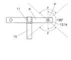
全天球画像を提供するときは、複数のカメラAi(i=1〜n)及びこれらを保持するホルダ11は、前記正多角形の中心Oから各カメラの撮影中心Pを通る方向を中心とする横方向に(2×360/n)+α度の領域外で、かつ、高さ方向に180+β度の領域外に位置させる。ここで、αは、観察装置3のディスプレイ31(31l、31r)の観察者に対する横方向の視野角、βは、同高さ方向の視野角、nは、正多角形の角数である。これにより、観察装置3は、カメラAiやホルダ11が写っていない全天球双眼立体視画像をディスプレイ31に表示することができる。
提供する画像が全方位画像のときは、高さ方向については、複数のカメラAi及びホルダ11をβ度の領域外に位置させれば良い。When providing an omnidirectional image, the plurality of cameras Ai (i = 1 to n) and the
When the provided image is an omnidirectional image, the plurality of cameras Ai and the
一組の画面Cの提供を受けた観察装置は、観察者の観察方向を検出し、一組の画面Cから検出した方向を挟む2個の撮影画面Bi、Bi±1を左目用及び右目用の画面として選択し、選択した画面から前記検出した方向を中心としかつ観察装置が備えるディスプレイ31l、31rの横方向の視野角αに相当する幅w及び高さ方向の視野角に相当する高さhを備えた表示画面Dl、Drを切り出してディスプレイ31l、31rに表示する。 The observation apparatus that has received a set of screens C detects the observation direction of the observer, and uses two imaging screens Bi and Bi ± 1 for the left eye and the right eye that sandwich the directions detected from the set of screens C. And a width w corresponding to the viewing angle α in the horizontal direction and a height corresponding to the viewing angle in the height direction of the
通常、一組の画面の提供は、画像配信用のサーバ2によってインターネット4を介して行われる。インターネット4を介して一組の画面Cを受信する観察装置3は、当該画像の受信手段32と、左目用と右目用の画像を表示するための2個のディスプレイ31l、31rと、ゴーグルが向く方向(全天球画像を受信するときは横方向及び高さ方向、全方位画像を受信するときは少なくとも横方向)を検出する方向検出手段33と、方向検出手段33が検出した方向に応じて一組の画面Cから左目用と右目用の画面を選択する画面選択手段34と、選択した画面Bi、Bi±1から左目用と右目用の表示画面Dl、Drを切り出す画面切り出し手段35と、切り出した画面をディスプレイに表示する表示手段36とを備えている。 Normally, a set of screens is provided via the Internet 4 by the
この発明により、それぞれの方向の画像の撮影を受け持つ複数のカメラが撮影した画面を繋ぎ合わせることなく、観察装置の方向に応じた全天球ないし全方位の画像を遠隔地で観察できる。 According to the present invention, an omnidirectional or omnidirectional image corresponding to the direction of the observation device can be observed at a remote place without connecting the screens captured by a plurality of cameras that are responsible for capturing images in the respective directions.
そして、画面の繋ぎ処理を必要としないので、画像データの複雑な処理が不要となり、データ処理に時間がかからないため多数の画像を次々と配信しなければならないライブ動画の提供が可能になるという効果がある。 In addition, since no screen connection processing is required, complicated processing of image data is not required, and since it does not take time for data processing, it is possible to provide a live video in which a large number of images must be delivered one after another. There is.
以下、図面を参照してこの発明の実施形態を説明する。図1において、1はカメラユニット、2は画像配信用のコンピュータ(以下「配信サーバ」という)、3、3・・・は配信された画像の観察装置(立体視用端末。以下「ゴーグル」という)、4はインターネットである。 Embodiments of the present invention will be described below with reference to the drawings. In FIG. 1, 1 is a camera unit, 2 is a computer for image distribution (hereinafter referred to as “distribution server”), 3, 3... Are observation devices for distributed images (stereoscopic terminal; hereinafter referred to as “goggles”). ) 4 is the Internet.
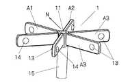
カメラユニット1は、図2に拡大して示すように、ホルダ11にn個(図では6個)の全天球カメラAi(i=1〜n)を放射状に取り付けた構造で、図2のホルダ11は、支柱15の上端に取り付けられている。各カメラAiが撮影した静止画及び動画は、それぞれのカメラに接続したケーブル12で配信サーバ2に送られている。各カメラAiは、複数のレンズ(図では2個)13、14を備えており、レンズ間の中心点を撮影中心とする全天球画像を撮影する。 The
双眼立体視画像を得るためには、少なくとも2個のカメラが必要である。各カメラAiの撮影画像には自分自身は写らないが、隣接して配置される他のカメラやカメラを保持しているホルダ11は映る。複数のカメラAiは、隣接するカメラやホルダが写っている複数の画像から、隣接するカメラやホルダが写っていない右目用と左目用の全天球画像が得られるようにホルダ11に装着されている。 In order to obtain a binocular stereoscopic image, at least two cameras are required. The photographed image of each camera Ai does not show itself, but the other camera arranged adjacently and the
図の例では、各カメラAiは、そのレンズ13、14の光軸を同一平面上にして、それらの光軸が当該平面上の正多角形の各辺の方向を向くように取り付けられている。ホルダ11は、複数のカメラAiの配置中心に位置しており、あるカメラの撮影画像中のホルダや隣接するカメラが写り込んでいる方角が他のカメラの撮影画像で補填されるように、複数個のカメラAiが取り付けられている。複数のカメラAiは、静止画であれ動画であれ、同一のタイミングで撮影動作を行うように同期制御されている。 In the example of the figure, each camera Ai is mounted so that the optical axes of its
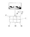
配信サーバ2は、図3に示すように、カメラユニットのn個の各カメラAiが同時に撮影したn個の撮影画面Biを受信し、それらを一組の画面Cにしてインターネット4を介してゴーグル3・・・に配信する。複数のカメラAiには同時に撮影信号が与えられるが、カメラの性能によっては、正確にタイミングの一致した撮影を行うことができない場合がある。そのような場合には、複数の撮影画面Biを一組の画面Cとする前に、撮影タイミングのずれを修正するための補正を行う。例えば短い時間間隔で撮られた画像間のずれから、タイミングがずれた分の画像の変位を演算して画像を補正する。 As shown in FIG. 3, the
ゴーグル3は、左目用と右目用のディスプレイ31l、31rと、ジャイロと角加速度計や、水準器とコンパスなど、ゴーグルを付けた観察者が見る方向、少なくとも見る方向の変化を検出する方向検出手段33を備えている。ゴーグル3は、更に、方向検出手段33が検出した方向に応じて一組の画面C内のn個の撮影画面Biから左目用と右目用の画面を選択する画面選択手段34と、選択した画面から左目用と右目用のディスプレイに映し出す表示画面Dl、Drを切り出す画面切り出し手段35と、切り出した画面をそれぞれのディスプレイ31l、31rに表示する表示手段36とを備えている。 The
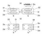
カメラユニット1が、図5に示すように、カメラA1とA2の2等分線の方向Nを基準方向である北に向けて設置されているとする。ゴーグル3がコンパスを備えていれば、基準方向からの自分自身の向きを検出できるので、その向いている方向の両側に配置されたカメラを右目用と左目用の撮影画面Bi、Bi±1として選択し、画面切り出し手段35は、それぞれの画面B1、B2から左右のディスプレイ31l、31rに映し出す幅wと高さhの表示画面Dl、Drを切り出す。 As shown in FIG. 5, it is assumed that the
ゴーグル3が角加速度計と水準器を備えており、電源が投入されたときのゴーグルの向きを基準方向に設定する仕様であれば、観察者がゴーグルの電源を入れたとき、画面選択手段34は、受信した一組の画面Cから、カメラA1の撮影画面B1を左目用の画面、カメラA2の撮影画面B2を右目用の画面として選択し、画面切り出し手段35は、それぞれの画面B1、B2から左右のディスプレイ31l、31rに映し出す幅wと高さhの表示画面Dl、Drを切り出す。 If the
全ての撮影画面Bの幅中心をカメラユニットの基準方向Nにすれば、図7(a)に示すように、ゴーグルが基準方向を向いているときに切り出される左目用と右目用の表示画面Dl、Drは、それぞれの撮影画面B1、B2の幅中心を幅中心として切り出される。 If the center of the width of all the shooting screens B is set to the reference direction N of the camera unit, as shown in FIG. 7A, the display screen D1 for left eye and right eye that is cut out when the goggles are facing the reference direction. , Dr is cut out with the width center of each of the photographing screens B1 and B2 as the width center.
図及び以下の記述では、切り出される画面を単純な矩形や扇形としているが、ゴーグルのディスプレイは単純な矩形ばかりでなく、また、ゴーグルには通常、接眼レンズが付いていてディスプレイ上の画像に歪みが生じることもあるので、切り出す画面Dl、Drは、それぞれのディスプレイや接眼レンズに応じた形状で切り出される。 In the figure and the following description, the screen to be cut out is a simple rectangle or fan shape, but the display of goggles is not only a simple rectangle, and goggles usually have eyepieces and the image on the display is distorted. Therefore, the screens Dl and Dr to be cut out are cut out in shapes corresponding to the respective displays and eyepieces.
全天球双眼立体視用のゴーグルでは、その横方向の向きを変えないでゴーグルを上方に向けると、切り出される表示画面Dlu、Druは上方に移動するが、球面を円筒面に展開している関係上、ゴーグルを上方に向けたときに切り出される画面は、上に向けるに従って横方向に広がり、かつ上辺が下辺より広い扇形に変形した画面Dlu、Druとなる。ゴーグルを水平から下方に向けたときは、横方向に広がった下辺が上辺より長い扇形に変形した画面Dld、Drdとなる。 In the omnidirectional binocular stereoscopic goggles, if the goggles are turned upward without changing the horizontal direction, the cut out display screens Dlu and Dru move upward, but the spherical surface is developed on a cylindrical surface. For this reason, the screens cut out when the goggles are directed upward are the screens Dlu and Dru that expand in the horizontal direction as they are directed upward and are deformed into a fan shape with the upper side wider than the lower side. When the goggles are directed downward from the horizontal, the screens Dld and Drd are transformed into a fan shape in which the lower side spreading in the horizontal direction is longer than the upper side.
表示手段36は、赤道上から切り出された画面Dl、Drをゴーグルの画角や接眼レンズに応じた適切な画像に変換してディスプレイ31l、31rに表示する。上方又は下方に向けた全天球双眼立体視用のゴーグルでは、幅広い扇形に切り出された画面DluとDru又はDldとDrdは、赤道上の表示画面Dl、Drと同じ縦横比の画面に変換してそれぞれのディスプレイに表示する。 The display means 36 converts the screens Dl and Dr cut out from the equator into appropriate images according to the angle of view of the goggles and the eyepieces, and displays them on the
ゴーグル3の方向を基準方向Nから右回りに移動させると、撮影画面B1とB2から切り出す表示画面Dl、Drの中心もゴーグルの向く方向に従って右へと移動する。ゴーグルの方向が同一高さの横方向のみの変化であれば、切り出される表示画面の幅wは一定である。カメラが6個の場合は、ゴーグルの方向が基準方向から左右に30度(±30度)の方向である間は、左目用と右目用の表示画面Dl、Drは、それぞれ撮影画面B1、B2からゴーグルが向いている方向を幅中心にして切り出される。 When the direction of the
ゴーグル3の方向が基準方向Nから±360/2n度(カメラAiの配置間隔の半分の角度、n=6では±30度)を超えたとき、撮影画面の変換が行われる。すなわち、カメラが6個の場合、ゴーグルの移動方向が右方向に30度を超えると、今まで右目用であった撮影画面B2が左目用の画面として選択され、右目用の画面としてカメラA2の1つ右側のカメラA3の撮影画面B3が選択される。更にゴーグルの向きが変わり、右回りに90度を超えたとき、左目用として撮影画面B3が選択され、右目用として撮影画面B4が選択される。図7(b)は、ゴーグルが基準方向Nから右回りにθ=120度移動したときの、選択される撮影画面と切り出し画面とが図7(a)からどのように変化するかを示している。 When the direction of the
同様に、ゴーグルの方向が当初の方向から左方向に30度を超えたときには、左目用として撮影画面B6が選択され、右目用として撮影画面B1が選択され、更に移動して左方向に90度超えたときには左目用として撮影画面B5が選択され、右目用として撮影画面B6が選択されることになる。 Similarly, when the direction of the goggles exceeds 30 degrees in the left direction from the initial direction, the shooting screen B6 is selected for the left eye, the shooting screen B1 is selected for the right eye, and is further moved to 90 degrees in the left direction. When it exceeds, the shooting screen B5 is selected for the left eye, and the shooting screen B6 is selected for the right eye.
全ての撮影画面Biをカメラユニットの基準方向Nを幅中心にして作成すれば、どの撮影画面が選択されているかに関わらず、切り出す表示画面Dl、Drの幅中心は、ゴーグルが向いている方向である。 If all the shooting screens Bi are created with the reference direction N of the camera unit as the center of the width, the center of the width of the display screens Dl and Dr to be cut out is the direction in which the goggles are facing, regardless of which shooting screen is selected. It is.
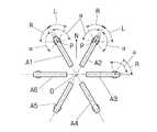
図8は、カメラが6個の場合について、ゴーグルの方向と撮影画面Bi(i=1〜6)の選択状態がどのようになるかを示した図である。図5に示すように、それぞれのカメラAi(i=1〜n)は、ゴーグルの水平方向の視野角をαとして、(2×360/n)+α度の領域、ここではn=6なので120+α度の領域を受け持っている。 FIG. 8 is a diagram showing the direction of goggles and the selection state of the shooting screen Bi (i = 1 to 6) when the number of cameras is six. As shown in FIG. 5, each camera Ai (i = 1 to n) has an area of (2 × 360 / n) + α degrees where α is the viewing angle in the horizontal direction of the goggles, and here n = 6, so 120 + α I am responsible for the area of the degree.
すなわち、各カメラAiが向いている方向から右回りに60度の範囲がその右隣のカメラと対となって左目用の画像を撮影する範囲L、右回りに60度の範囲がその左隣のカメラと対となって右目用の画像を撮影する範囲Rであり、切り出す表示画面の幅wの視野角がαなので、これらの範囲の外にα/2広げた範囲(2×360/n)+αが各カメラAiが受け持つ撮影範囲となる。 That is, a range of 60 degrees clockwise from the direction in which each camera Ai faces is a range L in which an image for the left eye is photographed as a pair with the camera on the right side, and a range of 60 degrees clockwise is the left side. Since the viewing angle of the width w of the display screen to be cut out is α, a range expanded by α / 2 outside these ranges (2 × 360 / n) ) + Α is the shooting range of each camera Ai.
各カメラの上記の受け持ち領域は、赤道上での領域である。全天球双眼立体視用のゴーグルでは、ゴーグルを上方や下方に向けたときに表示画面として撮影画面から切り取られる角度幅αが広がるので受け持つ領域も広がることになる。隣のカメラやホルダは、この各カメラが受け持つ領域内に写り込まないように、ホルダの形状寸法及びカメラの個数を決めれば良い。 The above-mentioned handling area of each camera is an area on the equator. In the omnidirectional binocular stereoscopic goggles, when the goggles are directed upwards or downwards, the angle width α cut out from the shooting screen as a display screen is widened, so the area to be handled is also widened. It is only necessary to determine the shape of the holder and the number of cameras so that the adjacent cameras and holders do not appear in the area of each camera.
ゴーグル3を真上及び真下に向けたときに切り出される画面にホルダ11が写り込まないようにするためには、ゴーグル3の高さ方向の視野角をβとして、高さ方向に180度+β度の領域にホルダ11が入り込まない大きさ及び形状とする(図6参照)。これにより、ゴーグルを真上及び真下に向けたとき、撮影画面を変換しないでゴーグル3が備える高さ方向の視野角βの画像をディスプレイに表示することができる。ゴーグルが真上及び真下を超えて移動したときは、その時点で選択されている撮影画面が変更されることになる。 In order to prevent the
上記の説明で理解されるように、各カメラの撮影した画面のなかにはゴーグルのディスプレイに表示されることのない範囲が存在する。従って、使用するカメラは、完全な全天球ないし全方位を撮影できるカメラに限らず、一部が欠けた全天球ないし全方位カメラであっても良い。例えば真下部分の頂角60度の円錐部分が写らない全天球カメラであっても、直下の方向をホルダ中心の方向にして配置して配信サーバでその方向を変換するようにすれば、この発明の全天球双眼立体視画像を提供できる。 As understood from the above description, there is a range that is not displayed on the goggles display in the screen shot by each camera. Therefore, the camera to be used is not limited to a camera that can capture a complete omnidirectional or omnidirectional camera, but may be a omnidirectional or omnidirectional camera that is partially missing. For example, even if it is an omnidirectional camera that does not show a cone part with an apex angle of 60 degrees directly below, if the direction directly below is placed in the direction of the center of the holder and the direction is changed by the distribution server, this The omnidirectional binocular stereoscopic image of the invention can be provided.
ホルダ11は、支柱15やヘルメットに取り付けられるが、このときの支柱15やヘルメットを装着している人の体などは、ゴーグルで観察する画像に写ることになる。この支柱やヘルメットは、人が現場で観察する場合も当然視野に入ることとなるので、これらが写り込んだ画像は、むしろ自然な画像であり、通常では、全天球画像や全方位画像を提供することの障害になることはない。 The
また、飛翔体にホルダ11を搭載して空中での全天球双眼立体視画像を提供することが可能である。この場合、小型の飛翔体であれば、ホルダ及び飛翔体を上述したカメラの横方向及び高さ方向の領域に入らない大きさ及び形状とし、撮影画面を無線で配信サーバーに送信すれば、空中からの双眼立体視画像を提供できる。 In addition, it is possible to provide a omnidirectional binocular stereoscopic image in the air by mounting the
このように、ゴーグルの向いている方向が60度(カメラの配置個数が6個の場合)変化する毎に左目用と右目用の撮影画面を、ゴーグルが向く方向の左側と右側のカメラの撮影画面とし、これらの撮影画面からゴーグルが向いている方向を幅中心として、ゴーグルに備えられているディスプレイの視野角に相当する幅w(横方向の角度α)、高さh(高さ方向の角度β)の表示画面を切り出して、左目用と右目用のディスプレイに表示することにより、全方位ないし全方位かつ全高さの双眼立体視が可能になるのである。 Thus, whenever the direction in which the goggles are directed changes by 60 degrees (when the number of cameras is six), the left and right eye photography screens are taken, and the left and right cameras in the direction in which the goggles are directed. The width w (lateral angle α) corresponding to the viewing angle of the display provided in the goggles and the height h (height direction) By cutting out the display screen of the angle β) and displaying it on the display for the left eye and the right eye, binocular stereoscopic vision of all directions or all directions and all heights becomes possible.
なお、表示画面を切り取る元となる撮影画面の切り換えは、図8の例では基準方向Nから±30度、±90度、±150度の方向で行われるが、必ずしも常にこれらの角度で撮影画面の切り換えを行わねばならない訳ではない。各撮影画面Biは、全方位の画面なので、例えば撮影画面B1から基準方向Nから35度右へ移動した表示画面を切り出すことも可能だからである。従って、ゴーグルの動きに対して少し時間遅れを与えて切り換えるようにすれば、ゴーグルが撮影画面を切り換える方向を向いているときのゴーグルの僅かな移動や振動によって、画像が頻繁に切り換えられるのを防止することができる。また、この切り換えの際に、短い時間でのフェードインとフェードアウトをしながら切り換えるようにして、画像が滑らかに切り換えられるようにすることもできる。 Note that, in the example of FIG. 8, switching of the shooting screen from which the display screen is cut is performed in directions of ± 30 degrees, ± 90 degrees, and ± 150 degrees from the reference direction N. However, the shooting screen is not always at these angles. You don't have to switch. This is because each photographing screen Bi is an omnidirectional screen, and for example, it is possible to cut out a display screen that has moved 35 degrees to the right from the reference direction N from the photographing screen B1. Therefore, if switching is performed with a slight time delay with respect to the movement of the goggles, images are frequently switched due to slight movement or vibration of the goggles when the goggles are facing the direction of switching the shooting screen. Can be prevented. Further, at the time of this switching, the images can be switched smoothly by switching while fading in and fading out in a short time.
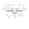
複数のカメラAの隣のカメラとのレンズ間距離は、人間の両眼の間隔を基準とするが、撮影対象物やゴーグルの仕様によっては、この距離を少し広げた方が自然な立体視に見える場合がある。このことを考慮すると、ホルダ11として隣のカメラとのレンズ間間隔を調整できるような構造のホルダを用いることが考えられる。 The distance between the lenses of the cameras next to the cameras A is based on the distance between both eyes of the human, but depending on the shooting target and the specifications of the goggles, it may be natural to stereoscopically increase the distance slightly. May be visible. Considering this, it is conceivable to use a holder having a structure that can adjust the distance between the lenses of the adjacent camera as the
そのようなホルダの構造として、例えばそれぞれのカメラを放射方向に摺動自在に取り付けて、円錐形のコーンの進退動作によって、レンズ間距離を可変にする構造などが考えられる。例えば図9に示すように、ホルダベース11aに放射方向に摺動自在に取り付けた支持台16に各カメラを搭載し、これらの支持台を縮退方向(放射方向内側へと移動する方向)に付勢するばね17を設け、ホルダ中心に設けたねじ18に螺合したコーン(円錐部材)19に支持台16の基端を当接させる構造である。 As a structure of such a holder, for example, a structure in which each camera is slidably mounted in the radial direction and the distance between the lenses is made variable by advancing and retracting the conical cone is conceivable. For example, as shown in FIG. 9, each camera is mounted on a
コーン19を回すと、ねじ作用によりコーンは上下する。コーン19を左向きに回してコーン19を上昇すれば、支持台16及びこれに取り付けたカメラAは、放射方向外側へと移動し、コーン19を右向きに回して下降すれば、ばね17の力によって支持台16及びこれに取り付けたカメラAは、放射方向内側へ移動するから、隣接するカメラ相互のレンズ間隔を調整することが可能である。 When the
なお、全天球画面の一部が全方位画面となることから理解されるように、この発明により、全方位画像の配信も行うことが可能で、カメラとして全方位カメラを用いて、全方位の双眼立体視画像を提供することもできる。 As will be understood from the fact that a part of the omnidirectional screen becomes an omnidirectional screen, the present invention can also deliver an omnidirectional image, using an omnidirectional camera as a camera, It is also possible to provide a binocular stereoscopic image.
1 カメラユニット
2 サーバ
3 観察装置
4 インターネット
11 カメラホルダ
31l、31r ディスプレイ
32 受信手段
33 方向検出手段
34 画面選択手段
35 画面切り出し手段
36 表示手段
Ai(i=1〜n) 全天球カメラ
Bi(i=1〜n)撮影画面
C 一組の画像
Dl、Dr 表示画面
h 表示画面の高さ
w 表示画面の幅
α 横方向の視野角
β 高さ方向の視野角DESCRIPTION OF
【0001】
技術分野
[0001]
この発明は、カメラの設置場所における全天球(全方位かつ全高さ)ないし全方位(全周)の双眼立体視画像を提供する方法、当該画像を配信する装置及びカメラユニットに関するものである。
背景技術
[0002]
本願出願人は、特許文献1において、カメラ設置場所の全方位の双眼立体視画像を提供する方法を開示している。この方法は、複数個の全方位カメラを人間の両眼の間隔に相当する間隔で配置し、これらのカメラが取得した全方位画面からそれぞれのカメラが分担する左目用と右目用の表示画面を切り出して繋ぎ合わせることによって、左目用と右目用の全方位画面を生成する。そして、それぞれの全方位画面から観察者が見ようとする方向の左目用と右目用の矩形画面を切り出して、観察者のディスプレイに表示するというものである。
[0003]
また、カメラ設置場所の全天球画像を撮影するカメラは、例えば特許文献2に開示されている。この種のカメラは、通常、複数の魚眼レンズで撮影した画像を、レンズの向きなどに関わりなく、上辺が真上で下辺が真下の全方位(360度)かつ全高さ(180度)の、高さ:幅が1:2の、矩形画像に変換して出力している。
先行技術文献
特許文献
[0004]
特許文献1:特許第4183466号公報
特許文献2:特開2013−66163号公報
発明の概要
発明が解決しようとする課題[0001]
Technical field [0001]
The present invention relates to a method for providing a binocular stereoscopic image of all celestial spheres (omnidirectional and total height) or omnidirectional (entire circumference) at a camera installation location, an apparatus for distributing the images, and a camera unit.
Background art [0002]
The applicant of the present application discloses a method of providing an omnidirectional binocular stereoscopic image of a camera installation location in
[0003]
A camera that captures an omnidirectional image of a camera installation location is disclosed in
Prior Art Literature Patent Literature [0004]
Patent Document 1: Japanese Patent No. 4183466 Patent Document 2: Japanese Patent Laid-Open No. 2013-66163 Summary of the Invention Problems to be Solved by the Invention
【0002】
[0005]
特許文献1で提案した方法は、複数のカメラで撮影した画像を繋ぎ合わせて左目用と右目用の全方位画面を作成している。撮影中心や撮影方向の異なる2つのカメラの画面を繋ぎ合わせると、その繋ぎ目の所で撮影対象物の画像に微小なずれが生ずる。そのため、画面を繋ぎ合わせる際に、このずれを補正するための補正処理を行わねばならない。
[0006]
しかし、カメラから撮影対象物までの距離によって繋ぎ目におけるずれの量が異なるので、補正が困難である。更に、この補正には複雑な処理が必要で、処理に時間がかかるため、動画を提供しようとすると処理量が膨大になり、ライブ動画を提供することができない。
[0007]
この発明は、撮影方向が異なる複数のカメラで撮影した全天球ないし全方位の画面を繋ぎ合わせるという処理を行うことなく、全天球ないし全方位の双眼立体視画像を配信する手段を提供することを課題としている。この発明により、カメラやカメラを保持するホルダが写っていない全天球ないし全方位の双眼立体視ライブ動画を配信することが可能になる。
課題を解決するための手段
[0008]
一辺の長さを人間の両眼の間隔に等しいか又は立体視が不自然とならない範囲で広くした正多角形の各頂点位置に、全方位ないし全天球カメラAi(i=1〜n)を配置する。各カメラAiが撮影した同一タイミングの撮影画面Biを一組の画面Cにして観察装置3に提供する。
[0009]
全天球画像を提供するときは、複数のカメラAi(i=1〜n)及びこれらを保持するホルダ11は、前記正多角形の中心Oから各カメラの撮影中心Pを通る方向を中心とする横方向に(2×360/n)+α度の領域外で、かつ、高さ方向に180+β度の領域外に位置させる。ここで、αは、観察装置3のディスプレイ31(31l、31r)の観察者に対する横方向の視野角、βは、同高さ方向の視野角、nは、正多角形の角数である。これにより、観察装置3は、カメラAiやホルダ11が写っていない全天球双眼立体視画像をディスプレイ31に表示することができる。
提供する画像が全方位画像のときは、高さ方向については、複数のカメラ[0002]
[0005]
In the method proposed in
[0006]
However, since the amount of shift at the joint varies depending on the distance from the camera to the object to be photographed, correction is difficult. Furthermore, since this correction requires complicated processing and takes time, the amount of processing becomes enormous when an attempt is made to provide a moving image, and a live moving image cannot be provided.
[0007]
The present invention provides means for distributing an omnidirectional or omnidirectional binocular stereoscopic image without performing a process of connecting omnidirectional or omnidirectional screens shot by a plurality of cameras having different shooting directions. It is an issue. According to the present invention, it is possible to distribute an omnidirectional or omnidirectional binocular stereoscopic live video in which a camera and a holder for holding the camera are not captured.
Means for Solving the Problems [0008]
An omnidirectional or omnidirectional camera Ai (i = 1 to n) is placed at each vertex position of a regular polygon having a side length equal to the distance between human eyes or wide as long as stereoscopic vision is not unnatural. Place. The imaging screen Bi taken at the same timing taken by each camera Ai is provided as a set of screens C to the
[0009]
When providing an omnidirectional image, the plurality of cameras Ai (i = 1 to n) and the
When the image to be provided is an omnidirectional image, multiple cameras are used in the height direction.
【0003】
Ai及びホルダ11をβ度の領域外に位置させれば良い。
[0010]
一組の画面Cの提供を受けた観察装置は、観察者の観察方向を検出し、一組の画面Cから検出した方向を挟む2個の撮影画面Bi、Bi±1を左目用及び右目用の画面として選択し、選択した画面から前記検出した方向を中心としかつ観察装置が備えるディスプレイ31l、31rの横方向の視野角αに相当する幅w及び高さ方向の視野角に相当する高さhを備えた表示画面Dl、Drを切り出してディスプレイ31l、31rに表示する。
[0011]
通常、一組の画面の提供は、画像配信用のサーバ2によってインターネット4を介して行われる。インターネット4を介して一組の画面Cを受信する観察装置3は、当該画像の受信手段32と、左目用と右目用の画像を表示するための2個のディスプレイ31l、31rと、ゴーグルが向く方向(全天球画像を受信するときは横方向及び高さ方向、全方位画像を受信するときは少なくとも横方向)を検出する方向検出手段33と、方向検出手段33が検出した方向に応じて一組の画面Cから左目用と右目用の画面を選択する画面選択手段34と、選択した画面Bi、Bi±1から左目用と右目用の表示画面Dl、Drを切り出す画面切り出し手段35と、切り出した画面をディスプレイに表示する表示手段36とを備えている。
発明の効果
[0012]
この発明により、それぞれの方向の画像の撮影を受け持つ複数のカメラが撮影した画面を繋ぎ合わせることなく、観察装置の方向に応じた全天球ないし全方位の画像であって当該画像にカメラやカメラを保持するホルダが写っていない画像を遠隔地で観察できる。
[0013]
そして、画面の繋ぎ処理を必要としないので、画像データの複雑な処理が不要となり、データ処理に時間がかからないため多数の画像を次々と配信しなければならないライブ動画の提供が可能になるという効果がある。
図面の簡単な説明
[0014]
[図1]ハードウェアの全体構成図
[図2]カメラユニットの斜視図
[図3]サーバーにおける画像の変換を示す図[0003]
Ai and the
[0010]
The observation apparatus that has received a set of screens C detects the observation direction of the observer, and uses two imaging screens Bi and Bi ± 1 for the left eye and the right eye that sandwich the directions detected from the set of screens C. And a width w corresponding to the viewing angle α in the horizontal direction and a height corresponding to the viewing angle in the height direction of the
[0011]
Normally, a set of screens is provided via the
Effects of the Invention [0012]
According to the present invention, it is an omnidirectional or omnidirectional image corresponding to the direction of the observation device without connecting the screens captured by the plurality of cameras responsible for capturing the images in the respective directions. It is possible to remotely observe an image in which the holder for holding is not shown.
[0013]
In addition, since no screen connection processing is required, complicated processing of image data is not required, and since it does not take time for data processing, it is possible to provide a live video in which a large number of images must be delivered one after another. There is.
BRIEF DESCRIPTION OF THE DRAWINGS [0014]
[FIG. 1] Overall hardware configuration diagram [FIG. 2] Perspective view of camera unit [FIG. 3] Diagram showing image conversion in server
Claims (9)
Translated fromJapanese隣接するカメラ相互のレンズ間間隔を略両眼の間隔とした正多角形の頂点位置に全方位ないし全天球カメラを配置し、
各カメラが撮影した同一タイミングの全方位ないし全天球画面を一組の画面として観察装置に提供し、
観察装置は、観察する方向を検出したときに、
提供された前記一組の画面から当該方向を挟む2個のカメラの撮影画面を左目用及び右目用の撮影画面として選択し、当該選択した撮影画面から前記方向を中心としかつ観察装置が備えるディスプレイの視野角に相当する幅及び高さを備えた表示画面を切り出して当該ディスプレイに表示する、双眼立体視画像の提供方法。A binocular stereoscopic image providing method for providing a binocular stereoscopic image in all directions or in all heights,
An omnidirectional or omnidirectional camera is placed at the apex position of a regular polygon whose distance between adjacent lenses is approximately the distance between both eyes.
Provide the observation device as a set of omnidirectional or omnidirectional screens of the same timing taken by each camera,
When the observation device detects the direction of observation,
Display of two cameras sandwiching the direction from the set of provided screens is selected as a left-eye and right-eye shooting screen, and the observation device includes a display centered on the direction from the selected shooting screen. A binocular stereoscopic image providing method in which a display screen having a width and a height corresponding to the viewing angle is cut out and displayed on the display.
Applications Claiming Priority (3)
| Application Number | Priority Date | Filing Date | Title |
|---|---|---|---|
| JP2015124978 | 2015-06-22 | ||
| JP2015124978 | 2015-06-22 | ||
| PCT/JP2016/068272WO2016208539A1 (en) | 2015-06-22 | 2016-06-20 | Method for providing binocular stereoscopic image, observation device, and camera unit |
Publications (2)
| Publication Number | Publication Date |
|---|---|
| JPWO2016208539A1true JPWO2016208539A1 (en) | 2018-05-24 |
| JP6845506B2 JP6845506B2 (en) | 2021-03-24 |
Family
ID=57585719
Family Applications (1)
| Application Number | Title | Priority Date | Filing Date |
|---|---|---|---|
| JP2017524895AActiveJP6845506B2 (en) | 2015-06-22 | 2016-06-20 | Binocular stereoscopic image provision method, distribution device and camera unit |
Country Status (5)
| Country | Link |
|---|---|
| US (1) | US20180184067A1 (en) |
| EP (1) | EP3313071A4 (en) |
| JP (1) | JP6845506B2 (en) |
| CN (1) | CN107646193B (en) |
| WO (1) | WO2016208539A1 (en) |
Families Citing this family (4)
| Publication number | Priority date | Publication date | Assignee | Title |
|---|---|---|---|---|
| CN111670577A (en)* | 2018-02-09 | 2020-09-15 | 索尼公司 | Image processing apparatus, image processing method, and image processing program |
| US11321857B2 (en) | 2018-09-28 | 2022-05-03 | Apple Inc. | Displaying and editing images with depth information |
| WO2020104989A1 (en)* | 2018-11-22 | 2020-05-28 | Slovenská Technická Univerzita V Bratislave | Arrangement of multiple cameras in a multi-directional stereo camera system |
| US20230336865A1 (en)* | 2021-12-03 | 2023-10-19 | Apple Inc. | Device, methods, and graphical user interfaces for capturing and displaying media |
Citations (6)
| Publication number | Priority date | Publication date | Assignee | Title |
|---|---|---|---|---|
| JPH08191419A (en)* | 1995-01-10 | 1996-07-23 | Yamaha Corp | Head mount display system |
| US20040027451A1 (en)* | 2002-04-12 | 2004-02-12 | Image Masters, Inc. | Immersive imaging system |
| US20070024701A1 (en)* | 2005-04-07 | 2007-02-01 | Prechtl Eric F | Stereoscopic wide field of view imaging system |
| JP2013033321A (en)* | 2011-08-01 | 2013-02-14 | Dainippon Printing Co Ltd | Movie presentation device |
| JP2014095808A (en)* | 2012-11-09 | 2014-05-22 | Nintendo Co Ltd | Image creation method, image display method, image creation program, image creation system, and image display device |
| JP2014131154A (en)* | 2012-12-28 | 2014-07-10 | Pioneer Electronic Corp | Video processor, video receiver, video transmitter and video processing method |
Family Cites Families (1)
| Publication number | Priority date | Publication date | Assignee | Title |
|---|---|---|---|---|
| JP5020398B1 (en)* | 2011-06-29 | 2012-09-05 | パナソニック株式会社 | Image conversion apparatus, camera, image conversion method and program |
- 2016
- 2016-06-20EPEP16814309.7Apatent/EP3313071A4/ennot_activeWithdrawn
- 2016-06-20CNCN201680033762.9Apatent/CN107646193B/ennot_activeExpired - Fee Related
- 2016-06-20WOPCT/JP2016/068272patent/WO2016208539A1/ennot_activeCeased
- 2016-06-20USUS15/735,988patent/US20180184067A1/ennot_activeAbandoned
- 2016-06-20JPJP2017524895Apatent/JP6845506B2/enactiveActive
Patent Citations (6)
| Publication number | Priority date | Publication date | Assignee | Title |
|---|---|---|---|---|
| JPH08191419A (en)* | 1995-01-10 | 1996-07-23 | Yamaha Corp | Head mount display system |
| US20040027451A1 (en)* | 2002-04-12 | 2004-02-12 | Image Masters, Inc. | Immersive imaging system |
| US20070024701A1 (en)* | 2005-04-07 | 2007-02-01 | Prechtl Eric F | Stereoscopic wide field of view imaging system |
| JP2013033321A (en)* | 2011-08-01 | 2013-02-14 | Dainippon Printing Co Ltd | Movie presentation device |
| JP2014095808A (en)* | 2012-11-09 | 2014-05-22 | Nintendo Co Ltd | Image creation method, image display method, image creation program, image creation system, and image display device |
| JP2014131154A (en)* | 2012-12-28 | 2014-07-10 | Pioneer Electronic Corp | Video processor, video receiver, video transmitter and video processing method |
Also Published As
| Publication number | Publication date |
|---|---|
| EP3313071A4 (en) | 2019-01-23 |
| US20180184067A1 (en) | 2018-06-28 |
| JP6845506B2 (en) | 2021-03-24 |
| CN107646193A (en) | 2018-01-30 |
| EP3313071A1 (en) | 2018-04-25 |
| WO2016208539A1 (en) | 2016-12-29 |
| CN107646193B (en) | 2020-01-21 |
Similar Documents
| Publication | Publication Date | Title |
|---|---|---|
| CN107111928B (en) | Display system for remote control work machine | |
| US10416757B2 (en) | Telepresence system | |
| US7429997B2 (en) | System and method for spherical stereoscopic photographing | |
| EP2569951B1 (en) | System and method for multi-viewpoint video capture | |
| US20170269367A1 (en) | Microlens array-based near-eye display (ned) | |
| US11184597B2 (en) | Information processing device, image generation method, and head-mounted display | |
| JP6845506B2 (en) | Binocular stereoscopic image provision method, distribution device and camera unit | |
| CN107529053A (en) | Panorama three-dimensional image pickup device | |
| CN107333051B (en) | A kind of interior panoramic video generation method and device | |
| CN101285935A (en) | Anti-corona device for image display | |
| JP2018110295A5 (en) | ||
| ES2824049T3 (en) | System and method for remote monitoring of at least one observation area | |
| US9479761B2 (en) | Document camera, method for controlling document camera, program, and display processing system | |
| US20130021448A1 (en) | Stereoscopic three-dimensional camera rigs | |
| JP6043408B1 (en) | Simulated experience system, simulated experience method, portable device and simulated experience program | |
| JP7395296B2 (en) | Image processing device, image processing method, and program | |
| JP5223096B2 (en) | 3D video shooting control system, 3D video shooting control method, and program | |
| CN205318020U (en) | Head -wearing display equipment | |
| EP3848164A1 (en) | Robot system | |
| JP4183466B2 (en) | Method for generating omnidirectional binocular stereoscopic image | |
| JP2012216935A (en) | Information processing system, search device and program | |
| JP2011182003A (en) | Panorama camera and 360-degree panorama stereoscopic video system | |
| KR20160028165A (en) | Apparatus and method for recording panorama stereo image | |
| KR101549874B1 (en) | 3-dimensional moving picture photographing camera and using method for the same | |
| JPH0435395A (en) | Stereoscopic monitor |
Legal Events
| Date | Code | Title | Description |
|---|---|---|---|
| A529 | Written submission of copy of amendment under article 34 pct | Free format text:JAPANESE INTERMEDIATE CODE: A5211 Effective date:20171219 | |
| A521 | Request for written amendment filed | Free format text:JAPANESE INTERMEDIATE CODE: A821 Effective date:20171219 | |
| A621 | Written request for application examination | Free format text:JAPANESE INTERMEDIATE CODE: A621 Effective date:20190618 | |
| A521 | Request for written amendment filed | Free format text:JAPANESE INTERMEDIATE CODE: A523 Effective date:20191108 | |
| A131 | Notification of reasons for refusal | Free format text:JAPANESE INTERMEDIATE CODE: A131 Effective date:20200630 | |
| A521 | Request for written amendment filed | Free format text:JAPANESE INTERMEDIATE CODE: A523 Effective date:20200827 | |
| A131 | Notification of reasons for refusal | Free format text:JAPANESE INTERMEDIATE CODE: A131 Effective date:20201117 | |
| A521 | Request for written amendment filed | Free format text:JAPANESE INTERMEDIATE CODE: A523 Effective date:20201211 | |
| TRDD | Decision of grant or rejection written | ||
| A01 | Written decision to grant a patent or to grant a registration (utility model) | Free format text:JAPANESE INTERMEDIATE CODE: A01 Effective date:20210112 | |
| A61 | First payment of annual fees (during grant procedure) | Free format text:JAPANESE INTERMEDIATE CODE: A61 Effective date:20210210 | |
| R150 | Certificate of patent or registration of utility model | Ref document number:6845506 Country of ref document:JP Free format text:JAPANESE INTERMEDIATE CODE: R150 | |
| R250 | Receipt of annual fees | Free format text:JAPANESE INTERMEDIATE CODE: R250 | |
| R250 | Receipt of annual fees | Free format text:JAPANESE INTERMEDIATE CODE: R250 |