JPWO2016199834A1 - Interdental cleaning tool - Google Patents
Interdental cleaning toolDownload PDFInfo
- Publication number
- JPWO2016199834A1 JPWO2016199834A1JP2017523684AJP2017523684AJPWO2016199834A1JP WO2016199834 A1JPWO2016199834 A1JP WO2016199834A1JP 2017523684 AJP2017523684 AJP 2017523684AJP 2017523684 AJP2017523684 AJP 2017523684AJP WO2016199834 A1JPWO2016199834 A1JP WO2016199834A1
- Authority
- JP
- Japan
- Prior art keywords
- cleaning
- base material
- core base
- soft
- recess
- Prior art date
- Legal status (The legal status is an assumption and is not a legal conclusion. Google has not performed a legal analysis and makes no representation as to the accuracy of the status listed.)
- Granted
Links
- 238000004140cleaningMethods0.000titleclaimsabstractdescription559
- 239000000463materialSubstances0.000claimsabstractdescription476
- 229920001971elastomerPolymers0.000claimsabstractdescription50
- 239000000806elastomerSubstances0.000claimsabstractdescription50
- 229920003002synthetic resinPolymers0.000claimsabstractdescription32
- 239000000057synthetic resinSubstances0.000claimsabstractdescription32
- 230000004323axial lengthEffects0.000claimsdescription3
- 238000004519manufacturing processMethods0.000abstractdescription36
- 238000003780insertionMethods0.000abstractdescription25
- 230000037431insertionEffects0.000abstractdescription25
- 238000000034methodMethods0.000abstractdescription13
- 239000011162core materialSubstances0.000description440
- 238000000465mouldingMethods0.000description187
- 238000005452bendingMethods0.000description28
- 239000000758substrateSubstances0.000description27
- 238000007493shaping processMethods0.000description13
- -1for examplePolymers0.000description9
- 230000002093peripheral effectEffects0.000description9
- 230000015572biosynthetic processEffects0.000description7
- 239000002184metalSubstances0.000description7
- 239000004743PolypropyleneSubstances0.000description6
- PPBRXRYQALVLMV-UHFFFAOYSA-NStyreneChemical compoundC=CC1=CC=CC=C1PPBRXRYQALVLMV-UHFFFAOYSA-N0.000description6
- 239000002657fibrous materialSubstances0.000description6
- 229920001155polypropylenePolymers0.000description6
- 238000012423maintenanceMethods0.000description5
- 230000008569processEffects0.000description5
- 229920001169thermoplasticPolymers0.000description5
- 239000004416thermosoftening plasticSubstances0.000description5
- 239000004952PolyamideSubstances0.000description4
- 230000007423decreaseEffects0.000description4
- 230000013011matingEffects0.000description4
- 238000002844meltingMethods0.000description4
- 230000008018meltingEffects0.000description4
- 229920002647polyamidePolymers0.000description4
- 229920001707polybutylene terephthalatePolymers0.000description4
- 239000000454talcSubstances0.000description4
- 229910052623talcInorganic materials0.000description4
- 238000001816coolingMethods0.000description3
- 230000008878couplingEffects0.000description3
- 238000010168coupling processMethods0.000description3
- 238000005859coupling reactionMethods0.000description3
- 230000007547defectEffects0.000description3
- 239000003365glass fiberSubstances0.000description3
- 239000000203mixtureSubstances0.000description3
- 239000007779soft materialSubstances0.000description3
- 238000012360testing methodMethods0.000description3
- KAKZBPTYRLMSJV-UHFFFAOYSA-NButadieneChemical compoundC=CC=CKAKZBPTYRLMSJV-UHFFFAOYSA-N0.000description2
- 230000008859changeEffects0.000description2
- 230000008602contractionEffects0.000description2
- 238000010586diagramMethods0.000description2
- 238000009826distributionMethods0.000description2
- 230000003670easy-to-cleanEffects0.000description2
- 230000000694effectsEffects0.000description2
- 239000011521glassSubstances0.000description2
- 238000002347injectionMethods0.000description2
- 239000007924injectionSubstances0.000description2
- 230000007246mechanismEffects0.000description2
- 239000010445micaSubstances0.000description2
- 229910052618mica groupInorganic materials0.000description2
- 238000011056performance testMethods0.000description2
- 239000000843powderSubstances0.000description2
- 230000009467reductionEffects0.000description2
- 238000004904shorteningMethods0.000description2
- NLHHRLWOUZZQLW-UHFFFAOYSA-NAcrylonitrileChemical compoundC=CC#NNLHHRLWOUZZQLW-UHFFFAOYSA-N0.000description1
- 0CCNCC*(C)CChemical compoundCCNCC*(C)C0.000description1
- 229920000049Carbon (fiber)Polymers0.000description1
- DQEFEBPAPFSJLV-UHFFFAOYSA-NCellulose propionateChemical compoundCCC(=O)OCC1OC(OC(=O)CC)C(OC(=O)CC)C(OC(=O)CC)C1OC1C(OC(=O)CC)C(OC(=O)CC)C(OC(=O)CC)C(COC(=O)CC)O1DQEFEBPAPFSJLV-UHFFFAOYSA-N0.000description1
- 244000043261Hevea brasiliensisSpecies0.000description1
- 239000004695Polyether sulfoneSubstances0.000description1
- 239000004698PolyethyleneSubstances0.000description1
- 229920006311Urethane elastomerPolymers0.000description1
- 230000009471actionEffects0.000description1
- 239000000654additiveSubstances0.000description1
- 230000000996additive effectEffects0.000description1
- 150000001336alkenesChemical class0.000description1
- 229920006231aramid fiberPolymers0.000description1
- 239000004917carbon fiberSubstances0.000description1
- 229920006218cellulose propionatePolymers0.000description1
- 230000000052comparative effectEffects0.000description1
- 230000006835compressionEffects0.000description1
- 238000007906compressionMethods0.000description1
- 230000003247decreasing effectEffects0.000description1
- 230000002950deficientEffects0.000description1
- 230000000994depressogenic effectEffects0.000description1
- 229920006351engineering plasticPolymers0.000description1
- 229920001973fluoroelastomerPolymers0.000description1
- 238000001746injection mouldingMethods0.000description1
- 238000005259measurementMethods0.000description1
- VNWKTOKETHGBQD-UHFFFAOYSA-NmethaneChemical compoundCVNWKTOKETHGBQD-UHFFFAOYSA-N0.000description1
- 210000000214mouthAnatomy0.000description1
- 229920003052natural elastomerPolymers0.000description1
- 229920001194natural rubberPolymers0.000description1
- JRZJOMJEPLMPRA-UHFFFAOYSA-NolefinNatural productsCCCCCCCC=CJRZJOMJEPLMPRA-UHFFFAOYSA-N0.000description1
- 239000004033plasticSubstances0.000description1
- 229920003023plasticPolymers0.000description1
- 229920003229poly(methyl methacrylate)Polymers0.000description1
- 229920000515polycarbonatePolymers0.000description1
- 239000004417polycarbonateSubstances0.000description1
- 229920001123polycyclohexylenedimethylene terephthalatePolymers0.000description1
- 229920001225polyester resinPolymers0.000description1
- 239000004645polyester resinSubstances0.000description1
- 229920006393polyether sulfonePolymers0.000description1
- 229920000573polyethylenePolymers0.000description1
- 229920000139polyethylene terephthalatePolymers0.000description1
- 239000005020polyethylene terephthalateSubstances0.000description1
- 239000004926polymethyl methacrylateSubstances0.000description1
- 229920000098polyolefinPolymers0.000description1
- 229920002635polyurethanePolymers0.000description1
- 239000004814polyurethaneSubstances0.000description1
- 238000003825pressingMethods0.000description1
- 230000004044responseEffects0.000description1
- 229920006395saturated elastomerPolymers0.000description1
- 229920002379silicone rubberPolymers0.000description1
- 229920003051synthetic elastomerPolymers0.000description1
- 239000005061synthetic rubberSubstances0.000description1
- 229920002725thermoplastic elastomerPolymers0.000description1
- 229920001187thermosetting polymerPolymers0.000description1
Images


Classifications
- A—HUMAN NECESSITIES
- A61—MEDICAL OR VETERINARY SCIENCE; HYGIENE
- A61C—DENTISTRY; APPARATUS OR METHODS FOR ORAL OR DENTAL HYGIENE
- A61C15/00—Devices for cleaning between the teeth
- A61C15/02—Toothpicks
- A—HUMAN NECESSITIES
- A46—BRUSHWARE
- A46B—BRUSHES
- A46B15/00—Other brushes; Brushes with additional arrangements
- A46B15/0093—Magazins or sets of brushes components, e.g. plurality of brushes linked as a package
- A—HUMAN NECESSITIES
- A46—BRUSHWARE
- A46B—BRUSHES
- A46B3/00—Brushes characterised by the way in which the bristles are fixed or joined in or on the brush body or carrier
- A46B3/005—Bristle carriers and bristles moulded as a unit
- A—HUMAN NECESSITIES
- A46—BRUSHWARE
- A46B—BRUSHES
- A46B5/00—Brush bodies; Handles integral with brushware
- A46B5/002—Brush bodies; Handles integral with brushware having articulations, joints or flexible portions
- A46B5/0025—Brushes with elastically deformable heads that change shape during use
- A46B5/0029—Head made of soft plastics, rubber or rubber inserts in plastics matrix
- A—HUMAN NECESSITIES
- A46—BRUSHWARE
- A46B—BRUSHES
- A46B9/00—Arrangements of the bristles in the brush body
- A46B9/02—Position or arrangement of bristles in relation to surface of the brush body, e.g. inclined, in rows, in groups
- A46B9/04—Arranged like in or for toothbrushes
- B—PERFORMING OPERATIONS; TRANSPORTING
- B29—WORKING OF PLASTICS; WORKING OF SUBSTANCES IN A PLASTIC STATE IN GENERAL
- B29C—SHAPING OR JOINING OF PLASTICS; SHAPING OF MATERIAL IN A PLASTIC STATE, NOT OTHERWISE PROVIDED FOR; AFTER-TREATMENT OF THE SHAPED PRODUCTS, e.g. REPAIRING
- B29C45/00—Injection moulding, i.e. forcing the required volume of moulding material through a nozzle into a closed mould; Apparatus therefor
- B29C45/14—Injection moulding, i.e. forcing the required volume of moulding material through a nozzle into a closed mould; Apparatus therefor incorporating preformed parts or layers, e.g. injection moulding around inserts or for coating articles
- B29C45/14065—Positioning or centering articles in the mould
- B—PERFORMING OPERATIONS; TRANSPORTING
- B29—WORKING OF PLASTICS; WORKING OF SUBSTANCES IN A PLASTIC STATE IN GENERAL
- B29C—SHAPING OR JOINING OF PLASTICS; SHAPING OF MATERIAL IN A PLASTIC STATE, NOT OTHERWISE PROVIDED FOR; AFTER-TREATMENT OF THE SHAPED PRODUCTS, e.g. REPAIRING
- B29C45/00—Injection moulding, i.e. forcing the required volume of moulding material through a nozzle into a closed mould; Apparatus therefor
- B29C45/16—Making multilayered or multicoloured articles
- B29C45/1676—Making multilayered or multicoloured articles using a soft material and a rigid material, e.g. making articles with a sealing part
- B—PERFORMING OPERATIONS; TRANSPORTING
- B29—WORKING OF PLASTICS; WORKING OF SUBSTANCES IN A PLASTIC STATE IN GENERAL
- B29C—SHAPING OR JOINING OF PLASTICS; SHAPING OF MATERIAL IN A PLASTIC STATE, NOT OTHERWISE PROVIDED FOR; AFTER-TREATMENT OF THE SHAPED PRODUCTS, e.g. REPAIRING
- B29C45/00—Injection moulding, i.e. forcing the required volume of moulding material through a nozzle into a closed mould; Apparatus therefor
- B29C45/17—Component parts, details or accessories; Auxiliary operations
- B29C45/26—Moulds
- B29C45/2626—Moulds provided with a multiplicity of narrow cavities connected to a common cavity, e.g. for brushes, combs
- A—HUMAN NECESSITIES
- A46—BRUSHWARE
- A46B—BRUSHES
- A46B2200/00—Brushes characterized by their functions, uses or applications
- A46B2200/10—For human or animal care
- A46B2200/1066—Toothbrush for cleaning the teeth or dentures
- A46B2200/108—Inter-dental toothbrush, i.e. for cleaning interdental spaces specifically
- A—HUMAN NECESSITIES
- A46—BRUSHWARE
- A46B—BRUSHES
- A46B5/00—Brush bodies; Handles integral with brushware
- A46B5/002—Brush bodies; Handles integral with brushware having articulations, joints or flexible portions
- A46B5/0033—Brush bodies; Handles integral with brushware having articulations, joints or flexible portions bending or stretching or collapsing
- A46B5/0037—Flexible resilience by plastic deformation of the material
- B—PERFORMING OPERATIONS; TRANSPORTING
- B29—WORKING OF PLASTICS; WORKING OF SUBSTANCES IN A PLASTIC STATE IN GENERAL
- B29C—SHAPING OR JOINING OF PLASTICS; SHAPING OF MATERIAL IN A PLASTIC STATE, NOT OTHERWISE PROVIDED FOR; AFTER-TREATMENT OF THE SHAPED PRODUCTS, e.g. REPAIRING
- B29C45/00—Injection moulding, i.e. forcing the required volume of moulding material through a nozzle into a closed mould; Apparatus therefor
- B29C45/14—Injection moulding, i.e. forcing the required volume of moulding material through a nozzle into a closed mould; Apparatus therefor incorporating preformed parts or layers, e.g. injection moulding around inserts or for coating articles
- B29C45/14065—Positioning or centering articles in the mould
- B29C2045/14147—Positioning or centering articles in the mould using pins or needles penetrating through the insert
Landscapes
- Engineering & Computer Science (AREA)
- Manufacturing & Machinery (AREA)
- Mechanical Engineering (AREA)
- Health & Medical Sciences (AREA)
- Life Sciences & Earth Sciences (AREA)
- Epidemiology (AREA)
- Dentistry (AREA)
- Animal Behavior & Ethology (AREA)
- General Health & Medical Sciences (AREA)
- Public Health (AREA)
- Veterinary Medicine (AREA)
- Moulds For Moulding Plastics Or The Like (AREA)
- Brushes (AREA)
Abstract
Translated fromJapaneseDescription
Translated fromJapanese本発明は、エラストマで被覆した清掃部を有する歯間清掃具に関するものである。 The present invention relates to an interdental cleaning tool having a cleaning portion covered with an elastomer.
歯間清掃具として、合成樹脂を含む基材部と、エラストマを含む軟質部とを備え、前記基材部は、ハンドル基材部と、前記ハンドル基材部の先端部に設けた細長い軸状の芯基材部とを有し、前記軟質部は、前記芯基材部を被覆する清掃用軟質部を少なくとも有し、前記ハンドル基材部で持ち手としてのハンドル部を構成し、前記芯基材部と清掃用軟質部とで歯間清掃用の清掃部を構成したものが実用化されている(例えば、特許文献1〜5参照。)。 As an interdental cleaning tool, a base part including a synthetic resin and a soft part including an elastomer are provided, and the base part includes a handle base part and an elongated shaft-like shape provided at a tip part of the handle base part A core base part, and the soft part has at least a soft cleaning part for covering the core base part, and the handle base part constitutes a handle part as a handle, and the core What comprised the cleaning part for interdental cleaning with the base-material part and the soft part for cleaning is utilized practically (for example, refer patent documents 1-5).
前記歯間清掃具の製造方法としては、第1金型の第1成形空間に合成樹脂材料を充填して基材部を製作し、第1金型にて成形した基材部を第2金型の第2成形空間にセットして、第2金型の第1型と第2型とに、第2成形空間の長さ方向(芯基材部の軸方向)に間隔をあけて対面状に設けた複数組の保持ピンで、芯基材部を第2成形空間の中央部に位置決め保持した状態で、第2成形空間にエラストマ材料を充填して軟質部を成形することで、歯間清掃具を得るようになした製造方法が広く採用されている。また、通常は、複数個の歯間清掃具を同時成形できるように、第1金型に複数個の第1成形空間を設けるとともに、第2金型に第1成形空間と同数の第2成形空間を設け、歯間清掃具を製作する際には、複数個の第1成形空間に対して合成樹脂材料を供給して、複数個の基材部がランナ部で連結されるように同時に製作し、ランナ部にて連結された複数個の基材部からなる一次成形品を第2金型の第2成形空間にセットして、複数個の第2成形空間にエラストマ材料を充填することで、複数個の歯間清掃具を同時成形するように構成している。 As a method for manufacturing the interdental cleaning tool, a base material part is manufactured by filling a first molding space of a first mold with a synthetic resin material, and the base part molded by the first mold is a second metal. Set in the second molding space of the mold, facing the first mold and the second mold of the second mold with an interval in the length direction of the second molding space (axial direction of the core base material) With a plurality of sets of holding pins provided at the center, the core base material portion is positioned and held in the center portion of the second molding space, and the soft material is molded by filling the second molding space with an elastomer material. A manufacturing method for obtaining a cleaning tool is widely adopted. In addition, normally, a plurality of first molding spaces are provided in the first mold so that a plurality of interdental cleaning tools can be simultaneously molded, and the second molding having the same number as the first molding spaces is provided in the second mold. When manufacturing the interdental cleaning tool by providing a space, the synthetic resin material is supplied to the plurality of first molding spaces and manufactured simultaneously so that the plurality of substrate parts are connected by the runner part. Then, by setting a primary molded product composed of a plurality of base material parts connected by a runner part in the second molding space of the second mold, and filling the plurality of second molding spaces with an elastomer material. A plurality of interdental cleaning tools are formed at the same time.
ところで、清掃部を歯間に対して挿入するときには、軸方向に対して大きな圧縮の力が作用する。また、臼歯間、特に大臼歯間を清掃する際には、口腔内に対して前後方向に挿入した歯間清掃具の先端部から中間部にかけて、60°〜90°湾曲させながら臼歯間に挿入する必要があり、また歯間清掃時には、湾曲させた状態で、臼歯間の隙間に対して清掃部を出し入れする必要があることから、清掃部に対して大きな曲げ荷重が作用する。このため、基材部を合成樹脂材料で構成した歯間清掃具では、歯間への挿入時や歯間清掃時における、清掃部の折れ対策が重要な課題の1つになっている。 By the way, when the cleaning part is inserted between the teeth, a large compression force acts in the axial direction. Also, when cleaning between molars, especially between molars, insert between the molars while curving from 60 ° to 90 ° from the tip to the middle of the interdental cleaning tool inserted in the front-rear direction with respect to the oral cavity. When cleaning between teeth, it is necessary to put in and out the cleaning portion with respect to the gap between the molar teeth in a curved state, so that a large bending load acts on the cleaning portion. For this reason, in the interdental cleaning tool in which the base material portion is made of a synthetic resin material, countermeasures against breakage of the cleaning portion during insertion between the teeth or during interdental cleaning are one of the important issues.
清掃部の折れ対策として、基材部を構成する合成樹脂材料にガラス繊維を添加したものも提案されている。しかし、細長い清掃部の折れを防止できる十分な量のガラス繊維を添加すると、芯基材部の芯軸方向における強度剛性が高くなって、歯間部への挿入性は向上するが、芯基材部が撓み難くなることから挿入するためにより強い力が必要となり、臼歯間の清掃時に、芯基材部に大きな曲げ荷重が作用し易く、長さ方向の途中部で芯基材部が折れてしまうという問題があった。 As a countermeasure against breakage of the cleaning portion, a synthetic resin material constituting the base material portion with glass fiber added has been proposed. However, when a sufficient amount of glass fiber is added to prevent the elongate cleaning part from being broken, the strength rigidity in the core axis direction of the core base material part is increased, and the insertability into the interdental part is improved. Since the material part becomes difficult to bend, a stronger force is required for insertion, and a large bending load tends to act on the core base material part during cleaning between molars, and the core base material part breaks in the middle in the length direction. There was a problem that.
一方、芯基材部として、スーパーエンジニアリングプラスチック、例えばポリエーテルサルフォンを採用すると、芯基材部が撓み易くなって、清掃部の折れを抑制できるが、スーパーエンジニアリングプラスチックの成形には、高い射出温度が必須となり、射出成形後における冷却時間が長くなることから、歯間清掃具の生産性が低下し、また材料コストも高いことからトータルの製造コストがかなり高くなるという問題があった。 On the other hand, if super engineering plastic, for example, polyethersulfone, is used as the core base material part, the core base material part is easy to bend and can prevent the cleaning part from being bent. Since the temperature is essential and the cooling time after the injection molding becomes long, the productivity of the interdental cleaning tool is lowered, and the material cost is high, so that the total manufacturing cost is considerably increased.
本発明者は、芯基材部が折れる原因として、清掃用軟質部の成形時に第2金型において芯基材部を位置決めするための保持ピンと芯基材部の接触する位置に凹部が形成され易い点、この凹部の位置において芯基材部の横断面積が小さくなり、芯基材部に曲げの力が作用することによって生じる応力が高くなる点、高い応力が集中する部位に凹部が存在することで構造変化が生じやすくなり、歯間への挿入時や歯間清掃時に作用する曲げの力によって、凹部が形成される軸位置付近で芯基材部が折れる点、を見出した。 As a cause of the breakage of the core base material portion, the inventor forms a concave portion at a position where the holding pin for positioning the core base material portion and the core base material portion in the second mold come into contact with the second mold during molding. The easy point, the cross-sectional area of the core base material portion is reduced at the position of the concave portion, the stress generated by the bending force acting on the core base material portion is increased, and there is a concave portion in a portion where high stress is concentrated. As a result, it was found that the structural change is likely to occur, and the core base material part breaks in the vicinity of the axial position where the recess is formed due to the bending force acting during insertion between teeth or during interdental cleaning.
保持ピンにより芯基材部に凹部が形成されるメカニズムは明確ではないが、次のようなメカニズムにより凹部が形成されるものと推定できる。即ち、第1金型にて成形した基材部は、冷却後に第2金型にセットされるが、成形時間を短縮するため、比較的高温な状態で第2金型にセットされ、しかも第2金型にセットした基材部は、第2成形空間に充填した高温のエラストマに曝される関係上、清掃用軟質部の成形途中で軟化する。また、第2金型では、複数組の保持ピンを予め設定した突出長さだけ第2成形空間内へ突出させて、芯基材部を第2成形空間の中央部に位置決めすることになるが、成形時間を短縮することによる成形収縮差によって芯基材部の成形寸法のバラツキが発生したり、高温のエラストマに曝されることにより芯基材部の熱膨張や、エラストマの充填時における芯基材部の振動などにより、保持ピンの先端部が芯基材部に食い込んで、芯基材部に凹部が形成されるものと推定できる。 Although the mechanism by which the concave portion is formed in the core base material portion by the holding pin is not clear, it can be estimated that the concave portion is formed by the following mechanism. That is, the base material part molded with the first mold is set in the second mold after cooling, but in order to shorten the molding time, it is set in the second mold at a relatively high temperature, and The base material set in the two molds is softened during the molding of the cleaning soft portion because it is exposed to the high temperature elastomer filled in the second molding space. Further, in the second mold, a plurality of sets of holding pins are projected into the second molding space by a preset projection length, and the core base material portion is positioned at the center of the second molding space. Variations in the molding dimensions of the core base material due to molding shrinkage differences due to shortening of the molding time, or thermal expansion of the core base material due to exposure to a high temperature elastomer, and the core during elastomer filling It can be presumed that the tip portion of the holding pin bites into the core base material portion due to vibration of the base material portion, and a recess is formed in the core base material portion.
また、ハンドル部の中心線と芯基材部の軸線とを同軸状に配置した、所謂I型の歯間清掃具において、指で摘まみやすいようにするため、ハンドル部を扁平な形状に構成する場合には、通常、ハンドル部は第1金型及び第2金型の型開閉方向に対して扁平に構成し、また保持ピンは、金型構造をできるだけ簡単にするため、保持ピンの軸方向が第2金型の型開閉方向に配置されるように設けている。このため、I型の歯間清掃具では、ハンドル部を摘まんで臼歯間を清掃するときに、保持ピンにより形成される芯基材部の凹部が、湾曲する芯基材部の外周側と内周側とに配置され、内外周両側の凹部付近に大きな応力の集中が発生することで、芯基材部が折れ易くなることを見出した。 Further, in the so-called I-type interdental cleaning tool in which the center line of the handle part and the axis of the core base material part are arranged coaxially, the handle part is configured in a flat shape so that it can be easily picked up with fingers. In some cases, the handle portion is usually configured to be flat with respect to the mold opening and closing directions of the first mold and the second mold, and the holding pins are arranged in the axial direction of the holding pins in order to make the mold structure as simple as possible. Are arranged in the mold opening / closing direction of the second mold. For this reason, in the I-type interdental cleaning tool, when the handle portion is picked and the interdental teeth are cleaned, the concave portion of the core base material portion formed by the holding pins is formed on the outer peripheral side and the inner side of the curved core base material portion. It has been found that the core base material portion is easily broken by the large stress concentration occurring near the concave portions on both the inner and outer peripheral sides.
本発明の目的は、簡単な構成で、歯間清掃具の生産性を低下させることなく、歯間への挿入時や歯間清掃時における芯基材部の折れの発生を効果的に防止し得る、歯間清掃具を提供することである。 The object of the present invention is to effectively prevent the occurrence of the breakage of the core base material portion during insertion and interdental cleaning without reducing the productivity of the interdental cleaning tool with a simple configuration. It is to provide an interdental cleaning tool.
本発明は、以下の発明を包含する。
(歯間清掃具)
(1)合成樹脂を含む基材部と、前記基材部の少なくとも一部を被覆するエラストマを含む軟質部とを備え、前記基材部は、ハンドル基材部と、前記ハンドル基材部の先端部に連設した細長い軸状の芯基材部とを有し、前記軟質部は、前記芯基材部を被覆する清掃用軟質部を少なくとも有し、前記ハンドル基材部で持ち手としてのハンドル部を構成し、前記芯基材部と清掃用軟質部とで歯間清掃用の清掃部を構成した歯間清掃具であって、前記清掃部の第1側部と第2側部のそれぞれに、前記清掃用軟質部を貫通して、前記芯基材部に最大深さが0.01mm以上0.085mm以下の芯基材部凹部を形成する清掃部凹部を、前記清掃部の軸方向に間隔をあけて2箇所以上形成した、ことを特徴とする歯間清掃具。The present invention includes the following inventions.
(Interdental cleaning tool)
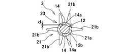
(1) A base material portion including a synthetic resin and a soft portion including an elastomer covering at least a part of the base material portion, wherein the base material portion includes a handle base material portion and a handle base material portion. An elongated shaft-shaped core base material portion connected to the tip portion, the soft portion has at least a cleaning soft portion covering the core base material portion, and the handle base material portion serves as a handle. An interdental cleaning tool comprising an interdental cleaning portion composed of the core base material portion and the cleaning soft portion, the first side portion and the second side portion of the cleaning portion. In each of the cleaning parts, a cleaning part recess that penetrates through the cleaning soft part and forms a core base part recess having a maximum depth of 0.01 mm or more and 0.085 mm or less is formed in the core base part. An interdental cleaning tool, wherein two or more portions are formed at intervals in the axial direction.
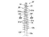
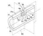
なお、芯基材部凹部の最大深さとは、芯基材部凹部の開口部の外面から底面までの最短距離のうち最も大きな距離(芯基材部凹部の深さの最大値)を意味する。具体的に説明すると、まず、図22に示すように、芯基材部の長さ方向の中心線(図22のCL)を通る平面(図22のBS)と芯基材部凹部の端との接点(図22のB点およびT点)を結ぶ直線(図22のUL)を設定する。次に、ULの任意の点からCLに対して降ろした垂線(図22のDL)を設定する。このDLにおけるULとの交点(図22のC1)と、芯基材部凹部の底面(図22のCS)との交点(図22のC2)、を結ぶ直線(図22のDLa)の長さについて測定する。DLaの長さの測定は、B点とT点間(UL直線間)で測定しつつ、BSをCL中心に回転させながら行い、得られたDLa数値の最大値を「芯基材部凹部の最大深さ」とする。また、清掃部の第1側部と第2側部とは、清掃部を成形する第2金型における、一方の金型にて成形される清掃部の外周面の片側半部と、他方の金型にて成形される清掃部の外周面の残りの片側半部を意味する。 In addition, the maximum depth of the core substrate portion recess means the largest distance (maximum depth of the core substrate portion recess) among the shortest distances from the outer surface to the bottom surface of the opening of the core substrate portion recess. . Specifically, first, as shown in FIG. 22, a plane (BS in FIG. 22) passing through the center line (CL in FIG. 22) in the length direction of the core base material portion and the end of the core base material recess portion A straight line (UL in FIG. 22) connecting the contact points (B and T in FIG. 22) is set. Next, a perpendicular line (DL in FIG. 22) drawn from CL at any point of UL is set. The length of a straight line (DLa in FIG. 22) that connects the intersection (C1 in FIG. 22) with the UL in this DL and the intersection (C2 in FIG. 22) with the bottom surface (CS in FIG. 22) of the core substrate recess. Measure about. The measurement of the length of DLa is performed while rotating the BS around the CL center while measuring between the B point and the T point (between the UL straight lines). "Maximum depth". Moreover, the 1st side part and 2nd side part of a cleaning part are one side half part of the outer peripheral surface of the cleaning part shape | molded by one metal mold | die in the 2nd metal mold | die which forms a cleaning part, and the other side. It means the remaining half on one side of the outer peripheral surface of the cleaning part formed by a mold.
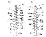
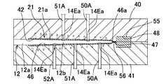
この歯間清掃具を製造する際には、第1金型の第1成形空間に合成樹脂材料を充填して基材部を成形し、第1金型にて成形した基材部を第2金型の第2成形空間にセットして、第2金型の第1型と第2型とに、第2成形空間の長さ方向に間隔をあけて設けた複数組の保持ピンで、芯基材部を第2成形空間の中央部に保持した状態で、第2成形空間にエラストマ材料を充填して軟質部を成形することになる。そして、このようにして製造した歯間清掃具における清掃部の第1側部と第2側部には、保持ピンの先端部が芯基材部と接触する位置に清掃部凹部が形成され、また芯基材部には、保持ピンの先端部が当接されて形成する、複数組の芯基材部凹部が芯基材部の軸方向に間隔をあけて発生することになる。 When manufacturing this interdental cleaning tool, the first molding space of the first mold is filled with a synthetic resin material to mold the base material portion, and the base material portion molded by the first mold is used as the second base material portion. A plurality of holding pins that are set in the second molding space of the mold and provided in the first mold and the second mold of the second mold with a space in the length direction of the second molding space, With the base material portion held in the center of the second molding space, the soft material is molded by filling the second molding space with an elastomer material. And the cleaning part recessed part is formed in the position where the front-end | tip part of a holding pin contacts a core base material part in the 1st side part and 2nd side part of the cleaning part in the interdental cleaning tool manufactured in this way, Also, a plurality of sets of core base material recesses formed by contacting the tip of the holding pin in the core base material portion are generated at intervals in the axial direction of the core base material portion.
そして、この歯間清掃具では、前記芯基材部に形成される芯基材部凹部の最大深さを0.01mm以上0.085mm以下に構成しているので、芯基材部凹部の形成位置における芯基材部の横断面積(芯基材部の軸方向に直交する断面積)の減少を抑制して、芯基材部凹部における応力集中の発生を抑制するとともに、応力が集中する位置に凹部構造が存在しても芯基材部構造変化に影響を与えにくくなることから、歯間への挿入時や歯間清掃時における芯基材部の折れを効果的に防止できる。このため、生産性に優れた合成樹脂材料で基材部を構成しつつ、歯間への挿入時や歯間清掃時における芯基材部の折れを効果的に防止できる。 And in this interdental cleaning tool, since the maximum depth of the core base material part recessed part formed in the said core base material part is comprised in 0.01 mm or more and 0.085 mm or less, formation of a core base material part recessed part The position where stress is concentrated while suppressing the reduction of the cross-sectional area of the core base material portion at the position (cross-sectional area perpendicular to the axial direction of the core base material portion) to suppress the stress concentration in the concave portion of the core base material portion. Even if there is a recess structure, it is difficult to affect the change in the structure of the core base material portion, so that it is possible to effectively prevent the core base material portion from being bent during insertion between teeth or during interdental cleaning. For this reason, it is possible to effectively prevent the core base material portion from being bent during insertion between teeth or during interdental cleaning while forming the base material portion with a synthetic resin material excellent in productivity.
(2)前記第1側部と第2側部とで対をなす複数組の清掃部凹部のうちの少なくとも1組の2個の清掃部凹部を、前記清掃部の周方向に重複しないように、前記清掃部の軸方向に間隔をあけて形成した(1)記載の歯間清掃具。この発明では、第1側部と第2側部とで対をなす複数組の清掃部凹部のうちの少なくとも1組の2個の清掃部凹部が、前記清掃部の周方向に重複しないように、前記清掃部の軸方向に間隔をあけて形成されているので、軟質部の成形時に、芯基材部の第1側部と第2側部とに交互に芯基材部凹部が形成され、芯基材部の軸方向の同じ位置に1対の芯基材部凹部が形成されることを防止できるので、芯基材部凹部に対応する位置における芯基材部の横断面積が周方向に重複する保持ピンの場合に比べ大きくなり、芯基材部の折れの発生を防止できる。また、各々の保持ピンが芯基材部に対して力を与える芯基材部軸方向の位置が重複しないので、周方向に重複する関係にある保持ピンの配設の場合に比べ芯基材部が力を受ける芯基材部軸方向の部分が長くなる。これにより、芯基材部はより強くホールドされ、軟質部20の成形時に形成される芯基材部凹部14Eaが深くなることが抑制される。従って、芯基材部凹部14Eaに対応する位置における芯基材部12の横断面積が大きくなり、芯基材部12の折れの発生を防止できる。更に、芯基材部の長さ方向に対する保持ピンの間隔が実質的に短くなるので、芯基材部を安定性良く保持することが可能となる。このため、生産性に優れた合成樹脂材料で基材部を構成しつつ、歯間への挿入時や歯間清掃時における芯基材部の折れを効果的に防止できる。なお、「芯基材部凹部の深さ」とは、芯基材部の長さ方向の中心線(図22のCL)を通る平面(図22のBS)と芯基材部凹部の端との接点(図22のB点およびT点)を結ぶ直線(図22のUL)を設定する。次に、ULの任意の点からCLに対して降ろした垂線(図22のDL)を設定する。このDLにおける、ULとの交点(図22のC1)と芯基材部凹部の底面(図22のCS)との交点(図22のC2)を結ぶ直線(図22のDLa)の長さを意味する。「周方向に重複しない」とは、組を成す2本の保持ピンの清掃部凹部を清掃部の円周方向に移動させた場合であっても、2つの清掃凹部が重なり合うことがない位置関係にあることを意味する。また、「芯基材部凹部の深さ」とは、第2金型での成形時において、保持ピンが芯基材部に当接することにより生じた芯基材部の変形度合い(圧縮変形した距離)を意味する。なお、前記清掃部の軸方向に間隔をあけて形成した前記清掃部凹部以外の清掃部凹部は、芯基材部を挟んで対面状に形成することができる。なお、本明細書において、第1側部の清掃部凹部と対をなす第2側部の清掃部凹部とは、清掃部の先端から数えて同じ番目の清掃部凹部を意味する。「芯基材部の横断面積」とは、芯基材部の軸方向の中心軸(図22のCL)に直行する平面(図22のVS)における芯基材部の面積を意味する。「芯基材部凹部に対応する位置」とは、前記平面VSに芯基材部凹部が包含される直線CLの範囲(位置)を意味する。(2) At least one set of two cleaning section recesses among a plurality of cleaning section recesses paired with the first side portion and the second side portion so as not to overlap in the circumferential direction of the cleaning portion. The interdental cleaning tool according to (1), which is formed at an interval in the axial direction of the cleaning unit. In the present invention, at least one set of two cleaning section recesses among a plurality of cleaning section recesses paired with the first side portion and the second side portion does not overlap in the circumferential direction of the cleaning portion. Since the cleaning part is formed with an interval in the axial direction, the core base part recesses are alternately formed on the first side part and the second side part of the core base part when the soft part is molded. Since it is possible to prevent a pair of core base part recesses from being formed at the same position in the axial direction of the core base part, the cross-sectional area of the core base part at the position corresponding to the core base part recess is circumferential. It becomes larger than the case of holding pins overlapping each other, and the occurrence of breakage of the core base material portion can be prevented. In addition, since the position of the core base material portion axial direction in which each holding pin applies force to the core base material portion does not overlap, the core base material is compared with the case where the holding pins are in a relationship of overlapping in the circumferential direction. The part of the core base material part axial direction in which the part receives force becomes longer. Thereby, a core base material part is hold | maintained more strongly and it is suppressed that the core base material part recessed part 14Ea formed at the time of shaping | molding of the
(3)前記軸方向に間隔をあけて形成した少なくとも1組の清掃部凹部における、前記清掃部の軸方向に対する間隔を、該清掃部凹部の軸方向の最大長さの1/4以上の長さに設定した(2)記載の歯間清掃具。(3) In at least one set of cleaning portion recesses formed at intervals in the axial direction, the interval with respect to the axial direction of the cleaning portion is a length of 1/4 or more of the maximum axial length of the cleaning portion recess. The interdental cleaning tool as set forth in (2).
(4)前記複数の清掃部凹部のうちの少なくとも1つの清掃部凹部における芯基材部凹部の開口形状が、前記清掃部の軸方向に長い形状である(1)〜(3)のいずれか記載の歯間清掃具。前記形状の芯基材部凹部の形成は、該当する位置の保持ピンのピン先の形状を、形成する芯基材部凹部の形状と一致させることで実現できる。清掃用突起部の配設レイアウトの自由度を高めるためには芯基材部凹部の面積をできるだけ小さくする必要がある。例えば保持ピンのピン先形状が円形の場合、保持ピンのピン先の直径を小さくすると芯基材部凹部の面積は小さくなる。しかし、保持ピンのピン先の直径を小さくすると、芯基材部に対する保持ピンの接触面積が少なくなるため、芯基材部凹部の深さが深くなり易く、芯基材部凹部を設けた位置に応力集中が発生し易くなる。加えて、芯基材部の固定部位が少なくなるため、しっかりと固定するためには保持ピンの押圧を高める必要も生じることから、さらに芯基材部凹部を設けた位置に応力集中が発生し易くなる。芯基材部凹部を清掃部の軸方向に長い形状に形成することにより、清掃用突起部の配設レイアウトの自由度が向上する。また、芯基材部に対する第1側部と第2側部の保持ピンが芯基材部の異なる位置に対して力を与えるため、軟質部成形時における芯基材部の振動が同じ面積の円形保持ピンの場合に比べ抑えることができる。従って、軟質部成形時に形成される芯基材部凹部の深さを浅くでき、使用時における芯基材部凹部が存在する清掃部の位置での応力集中を効果的に防止できるので好ましい。特に、前記清掃部の周方向に重複しないように、前記清掃部の軸方向に間隔をあけて清掃部凹部を形成した場合は、さらに好ましい。なお、「清掃部の軸方向に長い形状」とは、芯基材部の中心線(図22のCL)方向もしくは芯基材部の中心線に対して螺旋の方向における最大長さと、芯基材部の中心線に垂直な平面(図22のVS)方向における最大長さを比較した場合に、芯基材部の中心線方向における最大長さ等の方が大きい形状を意味する。具体的には、楕円形、長円形、長方形、卵形、小判形/俵形(短辺部が曲線状の長方形、丸角長方形)、涙型形状、平行四辺形など清掃部軸の螺旋方向に長い形状、等が挙げられる。(4) Any one of (1) to (3), wherein the opening shape of the core base material recess in at least one of the plurality of cleaning recesses is long in the axial direction of the cleaning unit. The interdental cleaning tool. Formation of the core base part recess of the shape can be realized by matching the shape of the pin tip of the holding pin at the corresponding position with the shape of the core base part recess to be formed. In order to increase the degree of freedom in the layout of the cleaning protrusions, it is necessary to make the area of the core base material recess as small as possible. For example, when the pin tip shape of the holding pin is circular, the area of the core base portion recess is reduced when the diameter of the pin tip of the holding pin is reduced. However, if the diameter of the pin tip of the holding pin is reduced, the contact area of the holding pin with respect to the core base material portion decreases, so that the depth of the core base material concave portion is likely to be deep, and the position where the core base material concave portion is provided. Stress concentration is likely to occur. In addition, since the number of fixing parts of the core base material portion is reduced, it is necessary to increase the pressing force of the holding pin in order to firmly fix the core base material portion. It becomes easy. By forming the core base material concave portion into a shape that is long in the axial direction of the cleaning portion, the degree of freedom of the layout of the cleaning protrusions is improved. In addition, since the holding pins on the first side portion and the second side portion with respect to the core base material portion apply force to different positions of the core base material portion, the vibration of the core base material portion at the time of forming the soft portion has the same area. This can be suppressed compared to the case of a circular holding pin. Therefore, it is preferable because the depth of the concave portion of the core base material portion formed at the time of forming the soft portion can be reduced, and stress concentration at the position of the cleaning portion where the concave portion of the core base material portion is present during use can be effectively prevented. In particular, it is more preferable when the cleaning portion recess is formed with an interval in the axial direction of the cleaning portion so as not to overlap in the circumferential direction of the cleaning portion. The “long shape in the axial direction of the cleaning portion” means the maximum length in the direction of the center line (CL in FIG. 22) of the core base material portion or the spiral direction with respect to the center line of the core base material portion, and the core base. When the maximum length in the plane (VS in FIG. 22) direction perpendicular to the center line of the material part is compared, the maximum length in the center line direction of the core base material part and the like means a larger shape. Specifically, the spiral direction of the cleaning unit axis, such as oval, oval, rectangular, oval, oval / saddle shape (curved rectangle with short sides, rounded rectangle), teardrop shape, parallelogram, etc. Long shapes, etc.
(5)前記清掃部の軸方向に対する該清掃部凹部の配設間隔を、略一様若しくは前記清掃部の先端側へ行くにしたがって狭くなるように設定した(1)〜(4)のいずれか記載の歯間清掃具。つまり、清掃部の先端部は基端部よりも小径に構成される略直線状の細長い軸状の構造体で、清掃用軟質部の成形時の成形により加わる力に対して構造的に変化し易い。そこで、本発明のように、清掃部凹部の配設間隔を、前記清掃部の先端側へ行くにしたがって狭くなるように設定するか、略一様になるように設定すると、軟質部の成形時に芯基材部が所定の位置から移動することを抑止することが容易となる。特に、前記清掃部の軸方向に対する該清掃部凹部の配設間隔を、略一様な間隔に設定することが最も好ましい実施の形態である。このように構成すると、軟質部成形時において芯基材部が受ける外力が一様になりやすいことからより好ましい。(5) Any one of (1) to (4), wherein the interval between the cleaning portion recesses with respect to the axial direction of the cleaning portion is set to be substantially uniform or narrow toward the tip side of the cleaning portion. The interdental cleaning tool. In other words, the distal end of the cleaning part is a substantially straight and elongated shaft-like structure that has a smaller diameter than the base end part, and structurally changes with the force applied during molding of the cleaning soft part. easy. Therefore, as in the present invention, when the interval between the cleaning portion recesses is set so as to become narrower or substantially uniform as it goes to the tip end side of the cleaning portion, when the soft portion is molded, It becomes easy to prevent the core base material portion from moving from a predetermined position. In particular, it is the most preferred embodiment that the arrangement interval of the cleaning unit recesses with respect to the axial direction of the cleaning unit is set to a substantially uniform interval. If comprised in this way, since the external force which a core base material part receives at the time of soft part shaping | molding tends to become uniform, it is more preferable.
(6)第1側部および第2側部の各々において、前記複数の芯基材部凹部の開口面積を、互いに略同一若しくは前記複数の芯基材部凹部のうち最も先端側の芯基材部凹部が最も小さくなるように設定した(1)〜(5)のいずれか記載の歯間清掃具。なお、「芯基材部凹部の開口面積」とは、第2金型を用いた成形時における、保持ピンと芯基材部の接触していた面積を意味し、本願発明の歯間清掃具においてはエラストマを含む軟質部で被覆されていない芯基材部部分(図22のCS)の面積として確認することができる。芯基材部は細長い円錐様の構造体で先端側へ行くにしたがって、横断面積が小さくなるので、最も横断面積が小さくなる先端部における開口面積を最も小さくなるように設定することが好ましい。つまり、芯基材部凹部の開口面積は、第2成形空間の中央部に対して芯基材部を保持する保持ピンの先端部面積に応じて変化するので、前記芯基材部の最も先端側に位置する保持ピンの先端部面積は、他の位置の保持ピンの先端部面積と比較して略同一若しくは最も小さくなる。一方、第2成形空間における、清掃用軟質部を成形する成形部は、第2成形空間の先端側において通路面積が狭くなる。このため、本発明のように、前記芯基材部の最も先端側の芯基材部凹部の開口面積をできる限り小さく設定する、すなわち先端側の保持ピンの先端部面積を小さくして、第2成形空間の通路面積を極力大きく設定すると、エラストマ材料の流通抵抗を極力小さく設定できるとともに、各々の保持ピン付近で生じるカルマン渦の成形体や保持ピンに対する影響を更に抑えることができ、芯基材部の保持を向上させたり、清掃用軟質部成形部に対するエラストマ材料の充填不良を防止したりすることができる。なお、「芯基材部凹部の開口面積」とは、第2金型を用いた成形時における、保持ピンと芯基材部の接触していた面積を意味し、本願発明の歯間清掃具においてはエラストマを含む軟質部で被覆されていない芯基材部部分(図22のCS)の面積として確認することができる。(6) In each of the first side portion and the second side portion, the opening areas of the plurality of core base portion recesses are substantially the same as each other, or the core substrate on the most distal side among the plurality of core base portion recesses The interdental cleaning tool according to any one of (1) to (5), which is set so that the partial recesses are minimized. The “opening area of the core base part recess” means the area where the holding pin and the core base part are in contact during molding using the second mold. In the interdental cleaning tool of the present invention, Can be confirmed as the area of the core base material portion (CS in FIG. 22) that is not covered with the soft portion containing the elastomer. The core base material portion is a long and narrow cone-like structure, and its cross-sectional area decreases as it goes to the tip side. Therefore, it is preferable to set the opening area at the tip portion having the smallest cross-sectional area to be the smallest. That is, since the opening area of the core base portion recess changes according to the tip end area of the holding pin that holds the core base portion with respect to the central portion of the second molding space, the most distal end of the core base portion The tip end area of the holding pin located on the side is substantially the same or the smallest compared to the tip end area of the holding pin at the other position. On the other hand, the molding area for molding the cleaning soft part in the second molding space has a narrow passage area on the tip side of the second molding space. For this reason, as in the present invention, the opening area of the core base part recess on the most tip side of the core base part is set as small as possible, that is, the tip part area of the holding pin on the tip side is reduced, 2 When the passage area of the molding space is set as large as possible, the flow resistance of the elastomer material can be set as small as possible, and the influence of Karman vortex generated around each holding pin on the molded body and holding pin can be further suppressed. The holding | maintenance of a material part can be improved, and the filling defect of the elastomer material with respect to the soft part shaping | molding part for cleaning can be prevented. The “opening area of the core base part recess” means the area where the holding pin and the core base part are in contact during molding using the second mold. In the interdental cleaning tool of the present invention, Can be confirmed as the area of the core base material portion (CS in FIG. 22) that is not covered with the soft portion containing the elastomer.
(7)前記芯基材部凹部に対応する位置における芯基材部の最大横断面積を、該芯基材部凹部に隣接する位置での芯基材部の横断面積を55.0〜99.6%に設定した、好ましくは70.0〜99.0%に設定した、最も好ましくは80.0〜97.9%に設定した(1)〜(6)のいずれか記載の歯間清掃具。このように構成すると、各々の芯基材部凹部における応力集中を少なくして、歯間への挿入時や歯間清掃時における芯基材部の折れを一層効果的に防止できる。なお、「芯基材部の横断面積」とは、芯基材部の中心線(図22のCL)に対して垂直な平面(図22のVS)と芯基材部が接する部分の面積を意味する。また、「芯基材部凹部に隣接する位置」とは、図22の芯基材部の軸方向の中心線(CL)に対して垂直な面VSが芯基材部凹部の端との接点を一つだけ有する場合の前記垂直な面VSとCLとの交点位置を意味する。一つの芯基材部凹部において「芯基材部凹部に隣接する位置」は2箇所存在する。これら2つの点における横断面積各々に対して、前記芯基材部凹部に対応する位置における芯基材部の最大横断面積を算出し、得られた2つの算出値がともに前記範囲内に存在する必要がある。また、「芯基材部凹部に対応する位置」とは、芯基材部の軸方向の中心線(CL)に対して垂直な面VSが芯基材部凹部の端との接点を有する場合の前記垂直な面VSとCLとの交点位置を意味する。すなわち、前記2つの「芯基材部凹部に隣接する位置」を結んだCL上の直線が相当する。(7) The maximum cross-sectional area of the core base material portion at a position corresponding to the core base material portion recess, and the cross-sectional area of the core base material portion at a position adjacent to the core base material portion recess is 55.0 to 99.99. The interdental cleaning tool according to any one of (1) to (6) set to 6%, preferably set to 70.0 to 99.0%, most preferably set to 80.0 to 97.9% . If comprised in this way, the stress concentration in each core base-material part recessed part will be decreased, and the breakage of the core base-material part at the time of insertion between teeth or the cleaning between teeth can be prevented more effectively. The “cross-sectional area of the core base material portion” means the area of the portion where the core base material portion is in contact with a plane (VS in FIG. 22) perpendicular to the center line (CL in FIG. 22) of the core base material portion. means. Further, the “position adjacent to the core base material recess” means that the surface VS perpendicular to the axial center line (CL) of the core base material portion of FIG. Means the position of the intersection of the vertical planes VS and CL. There are two “positions adjacent to the core substrate portion recess” in one core substrate portion recess. For each of the cross-sectional areas at these two points, the maximum cross-sectional area of the core base material portion at the position corresponding to the core base material recess is calculated, and the two obtained calculated values are both within the range. There is a need. The “position corresponding to the core base material recess” means that the surface VS perpendicular to the axial center line (CL) of the core base material has a contact point with the end of the core base material recess. Means the position of the intersection of the vertical planes VS and CL. That is, a straight line on the CL connecting the two “positions adjacent to the core base part recess” corresponds to the straight line.
(8)前記第1側部の複数の清掃部凹部と第2側部の複数の清掃部凹部とを芯基材部を挟んでそれぞれ対面状に形成した(1)〜(7)のいずれか記載の歯間清掃具。前述のように、清掃部凹部は第2金型に設けた保持ピンにより形成されるので、本発明のように構成すると、第2成形空間の中央部に対して複数の保持ピンにより芯基材部を安定性良く保持することができる。(8) Any of (1) to (7), wherein the plurality of cleaning portion recesses on the first side and the plurality of cleaning portion recesses on the second side are formed in a face-to-face relationship with the core base material portion interposed therebetween. The interdental cleaning tool. As described above, since the concave portion of the cleaning portion is formed by the holding pin provided in the second mold, when configured as in the present invention, the core substrate is formed by a plurality of holding pins with respect to the central portion of the second molding space. The portion can be held with good stability.
(9)前記第1側部と第2側部の少なくとも一方の側部に3個以上の清掃部凹部を形成した(1)〜(8)のいずれか記載の歯間清掃具。清掃部凹部を少なくとも一方の側部に3個以上設けると、歯間への挿入時や歯間清掃時に清掃部に作用する曲げの力によって生じる応力の偏在部分を、3個以上の清掃部凹部の形成位置に分散させることができ、局部的に大きな曲げの力が作用することによる芯基材部の折れを効果的に防止できる。しかも、清掃部凹部の個数を増やすと、軟質部を成形する第2金型に設ける保持ピンの本数が増えるので、芯基材部に対する保持ピンの接触面積が増大し、軟質部の成形時における芯基材部の振動を抑制でき、芯基材部凹部の深さを浅くする制御が行ない易くなるため、歯間清掃時における芯基材部凹部の位置における応力集中の発生を効果的に防止できるので好ましい。なお、第1側部と第2側部の清掃部凹部は同じ個数に設定することもできるし、異なる個数に設定することもできる。例えば、第1側部を第2側部よりも1つだけ清掃部凹部の個数を少なくすることができる。(9) The interdental cleaning tool according to any one of (1) to (8), wherein three or more cleaning unit recesses are formed on at least one side of the first side and the second side. When three or more cleaning unit recesses are provided on at least one side, uneven portions of stress caused by bending force acting on the cleaning unit during interdental insertion or interdental cleaning can be divided into three or more cleaning unit recesses. The core base material portion can be effectively prevented from being bent by a large bending force acting locally. In addition, increasing the number of cleaning part recesses increases the number of holding pins provided in the second mold for molding the soft part, so that the contact area of the holding pin with respect to the core base material part increases, and at the time of molding the soft part Since the vibration of the core base material can be suppressed and the control to reduce the depth of the core base material recess is facilitated, stress concentration at the position of the core base material recess is effectively prevented during interdental cleaning. It is preferable because it is possible. In addition, the cleaning part recessed part of a 1st side part and a 2nd side part can also be set to the same number, and can also be set to a different number. For example, the number of cleaning section recesses can be reduced by only one first side portion than the second side portion.
(10)前記ハンドル基材部と芯基材部とを略同一軸線上に配置した(1)〜(9)のいずれか記載の歯間清掃具。本発明のようにハンドル基材部と芯基材部とを略同一軸線上に配置すると、複数の歯間清掃具を並列状に密接配置して成形することができ、歯間清掃具の取り数を増やすことができるので好ましい。(10) The interdental cleaning tool according to any one of (1) to (9), wherein the handle base material portion and the core base material portion are disposed on substantially the same axis. When the handle base material portion and the core base material portion are arranged on substantially the same axis as in the present invention, a plurality of interdental cleaning tools can be closely arranged in parallel to be molded. This is preferable because the number can be increased.
(11)前記基材部を融点が150℃以上の結晶性を有する熱可塑性合成樹脂材料で構成した(1)〜(10)のいずれか記載の歯間清掃具。このような融点の熱可塑性合成樹脂材料を用いて基材部を成形すると、基材部の成形時間、特に冷却時間を短縮して生産効率を高めることにより、歯間清掃具の生産性を向上でき、ひいては歯間清掃具の製作コストを低減できる。(11) The interdental cleaning tool according to any one of (1) to (10), wherein the base material portion is made of a thermoplastic synthetic resin material having a crystallinity with a melting point of 150 ° C. or higher. When a base material part is molded using a thermoplastic synthetic resin material having such a melting point, the productivity of the interdental cleaning tool is improved by shortening the molding time of the base material part, in particular, the cooling time to increase the production efficiency. As a result, the manufacturing cost of the interdental cleaning tool can be reduced.
(12)最大深さが0.01mm以上0.085mm以下の芯基材部凹部を形成した清掃部凹部とそれ以外の凹部がある場合にはそれを含めて、前記第1側部と第2側部とで対をなす複数組の清掃部凹部のうちの少なくとも1組の清掃部凹部の中心を通る深さ方向の中心線分を、前記清掃用軟質部を成形する金型の型開閉方向に対して、前記清掃部の周方向に角度を付けて形成した(1)〜(11)のいずれか記載の歯間清掃具。このように構成すると、清掃用軟質部に外方へ突出する複数の清掃用突起部を形成する場合において、該清掃用突起部の配設レイアウトの自由度を向上できる。つまり、清掃部凹部は、芯基材部を第2成形空間の中央部に保持する保持ピンにより成形されるが、該保持ピンの位置を、清掃用突起部の形成位置に干渉しないように、第2成形空間に対して長さ方向及び周方向に調整できるので、該清掃用突起部の配設レイアウトの自由度を向上できる。(12) If there is a cleaning part recess having a core base part recess having a maximum depth of 0.01 mm or more and 0.085 mm or less and other recesses, the first side part and the second part are included. A mold opening / closing direction of a mold that molds the cleaning soft portion with a center line in a depth direction passing through the center of at least one set of cleaning portion recesses among a plurality of cleaning portion recesses paired with the side portion On the other hand, the interdental cleaning tool according to any one of (1) to (11), which is formed with an angle in the circumferential direction of the cleaning portion. If comprised in this way, when forming the some cleaning projection part which protrudes outward in the soft part for cleaning, the freedom degree of arrangement | positioning layout of this projection part for cleaning can be improved. That is, the cleaning portion recess is formed by the holding pin that holds the core base material portion in the center portion of the second molding space, but the position of the holding pin does not interfere with the formation position of the cleaning protrusion. Since it can adjust to a length direction and a circumferential direction with respect to the 2nd shaping | molding space, the freedom degree of arrangement | positioning layout of this cleaning projection part can be improved.
(13)前記基材部を構成する合成樹脂材料に、繊維材とタルクの少なくとも一方を添加した(1)〜(12)のいずれか記載の歯間清掃具。このように構成することで、芯基材部の曲げの力に対する強度剛性を高めることができ、歯間に対する清掃部の挿入性を向上できる。しかも、芯基材部の剛性を高めることができるので、芯基材部に形成される凹部の深さが深くなりにくくなり、芯基材部凹部を設けた位置における応力集中の発生を防止する上でも好ましい。(13) The interdental cleaning tool according to any one of (1) to (12), wherein at least one of a fiber material and talc is added to the synthetic resin material constituting the base portion. By comprising in this way, the rigidity rigidity with respect to the bending force of a core base-material part can be improved, and the insertion property of the cleaning part with respect to between teeth can be improved. Moreover, since the rigidity of the core base material portion can be increased, the depth of the concave portion formed in the core base material portion is difficult to increase, and the occurrence of stress concentration at the position where the core base material concave portion is provided is prevented. Also preferred above.
(歯間清掃具の製造方法)
(20)合成樹脂を含む基材部と、前記基材部の少なくとも一部を被覆するエラストマを含む軟質部とを備え、前記基材部は、ハンドル基材部と、前記ハンドル基材部の先端部に連設した細長い軸状の芯基材部とを有し、前記軟質部は、前記芯基材部を被覆する清掃用軟質部を少なくとも有し、前記ハンドル基材部で持ち手としてのハンドル部を構成し、前記芯基材部と清掃用軟質部とで歯間清掃用の清掃部を構成した歯間清掃具の製造方法であって、第1金型の第1成形空間に合成樹脂材料を供給して、前記基材部を成形する基材部成形工程と、前記基材部成形工程にて成形した基材部を、前記軟質部を成形する第2金型の第2成形空間にセットして、前記第2成形空間の長さ方向に間隔をあけて、前記第2金型の第1型と第2型とにそれぞれ2本以上設けた保持ピンのピン先端部を芯基材部に接触させ、適切な荷重を前記芯基材部に与えることで、前記芯基材部を清掃用軟質部成形部の略中央部に保持した状態で、前記第2成形空間にエラストマ材料を充填して軟質部を成形するとともに前記芯基材部に最大深さが0.01mm以上0.085mm以下の芯基材部凹部を形成する軟質部成形工程とを備えたことを特徴とする歯間清掃具の製造方法。(Manufacturing method of interdental cleaning tool)
(20) A base material part including a synthetic resin and a soft part including an elastomer covering at least a part of the base material part, wherein the base material part includes: a handle base material part; An elongated shaft-shaped core base material portion connected to the tip portion, the soft portion has at least a cleaning soft portion covering the core base material portion, and the handle base material portion serves as a handle. Is a manufacturing method of an interdental cleaning tool in which an interdental cleaning portion is configured by the core base material portion and the cleaning soft portion, in the first molding space of the first mold. Supplying a synthetic resin material to form a base material portion forming step, and forming a base material portion formed in the base material portion forming step into a second mold for forming the soft portion. Set in the molding space, leave an interval in the length direction of the second molding space, and connect it to the first mold and the second mold of the second mold The tip of the holding pin provided at least two is brought into contact with the core base material portion, and an appropriate load is applied to the core base material portion so that the core base material portion is substantially at the center of the soft part for cleaning. In the state held in the part, the second molding space is filled with an elastomer material to mold the soft part, and the core base part is provided with a core base part recess having a maximum depth of 0.01 mm or more and 0.085 mm or less. The manufacturing method of the interdental cleaning tool characterized by including the soft part formation process to form.
この歯間清掃具の製造方法では、芯基材部に形成される芯基材部凹部の最大深さを0.01mm以上0.085mm以下に設定しているので、複数の保持ピンにより、第2成形空間の適正位置に対して芯基材部を安定性良く保持することができ、歯間清掃具の成形精度を向上できるとともに、芯基材部凹部の形成位置における芯基材部の横断面積を十分に確保できるため、該部分における応力集中の発生が抑制され、歯間への挿入時や歯間清掃時における芯基材部の折れを防止できる。なお、芯基材部凹部の最大深さは、前記のとおり保持ピン先端部が芯基材部に与える荷重を調整する以外に、保持ピンの長さを調整したり、保持ピンを長さの異なるものと交換したりすることで、所望の深さに調整することができる。 In the manufacturing method of this interdental cleaning tool, since the maximum depth of the core base part recess formed in the core base part is set to 0.01 mm or more and 0.085 mm or less, 2 The core base material portion can be stably held with respect to the appropriate position in the molding space, the molding accuracy of the interdental cleaning tool can be improved, and the core base material portion is crossed at the formation position of the core base material recess. Since a sufficient area can be secured, the occurrence of stress concentration in the portion can be suppressed, and the core base material portion can be prevented from being bent during insertion between teeth or during interdental cleaning. Note that the maximum depth of the concave portion of the core base material portion can be adjusted by adjusting the length of the holding pin or by adjusting the length of the holding pin in addition to adjusting the load applied to the core base material portion by the holding pin tip as described above. It can be adjusted to a desired depth by exchanging it with a different one.
(21)前記第2成形空間の周方向に重複しないように、前記第2成形空間の長さ方向に間隔をあけて保持ピンを配置した場合および、前記第2成形空間の周方向に重複する保持ピンを配置した場合の各々において、前記芯基材部凹部に対応する位置における芯基材部の最大横断面積を、該芯基材部凹部に隣接する位置での芯基材部の横断面積の55.0〜99.6%、好ましくは70.0〜99.0%、最も好ましくは80.0〜97.9%に設定した(20)記載の歯間清掃具の製造方法。このように構成すると、使用時の芯基材部凹部における応力集中を少なくして、歯間への挿入時や歯間清掃時における芯基材部の折れを一層効果的に防止できる。(21) When holding pins are arranged at intervals in the length direction of the second molding space so as not to overlap in the circumferential direction of the second molding space, and in the circumferential direction of the second molding space. In each of the cases where the holding pins are arranged, the maximum cross-sectional area of the core base material portion at the position corresponding to the core base material recess is the cross-sectional area of the core base material portion at the position adjacent to the core base material recess. The manufacturing method of the interdental cleaning tool as described in (20) set to 55.0-99.6% of this, Preferably it is 70.0-99.0%, Most preferably, it is set to 80.0-97.9%. If comprised in this way, the stress concentration in the core base-material recessed part at the time of use can be reduced, and the breakage of the core base-material part at the time of the insertion between teeth or the cleaning between teeth can be prevented more effectively.
(22)前記第2金型の第1型の保持ピンと第2型の保持ピンとを、前記芯基材部を挟んで対面状に設けた(20)または(21)記載の歯間清掃具の製造方法。ここにおいて対面状とは、対になる保持ピンの先端部が接触する部位を結んだ直線が、芯基材部の軸中心付近を通過する位置にあること意味する。この場合には、芯基材部を、第2成形空間の中央部に対して複数の保持ピンにより安定性良く保持できる。(22) The interdental cleaning tool according to (20) or (21), wherein the first mold holding pin and the second mold holding pin of the second mold are provided so as to face each other with the core base material portion interposed therebetween. Production method. Here, the term “face-to-face” means that a straight line connecting portions where the tip portions of the holding pins to be in contact with each other passes through the vicinity of the axial center of the core base material portion. In this case, the core base material portion can be held with high stability by the plurality of holding pins with respect to the central portion of the second molding space.
(23)前記第2金型の第1型と第2型の少なくとも一方の型に3本以上の保持ピンを設けた(20)〜(22)のいずれか記載の歯間清掃具の製造方法。このように構成すると、清掃部の第1側部と第2側部の少なくとも一方の側部に、保持ピンにより3個以上の清掃部凹部が形成されるので、この製造方法により製作した歯間清掃具では、歯間への挿入時や歯間清掃時に清掃部に作用する曲げの力を、清掃部凹部が形成される3箇所以上の清掃部の位置で分散することができ、局部的に大きな曲げの力が作用することによる芯基材部の折れを効果的に防止できる。しかも、保持ピンを3本以上設けると、芯基材部に対する保持ピンの接触面積を増大して、軟質部の成形時における芯基材部の振動を抑制でき、形成される芯基材部凹部が深くなることを抑制できるため歯間清掃時における芯基材部凹部の深さを浅くして、歯間清掃時における芯基材部凹部の位置の応力集中の発生を効果的に防止できるので好ましい。なお、第2金型における第1型と第2型の保持ピンは同じ個数に設定することもできるし、異なる個数に設定することもできる。例えば、第1型を第2型よりも1つだけ保持ピンの個数を少なくすることができる。(23) The method for manufacturing an interdental cleaning tool according to any one of (20) to (22), wherein at least one of the first mold and the second mold of the second mold is provided with three or more holding pins. . If comprised in this way, since the 3 or more cleaning part recessed part is formed in the at least one side part of the 1st side part and 2nd side part of a cleaning part with a holding pin, it is the interdental produced by this manufacturing method. In the cleaning tool, the bending force acting on the cleaning part during interdental cleaning or interdental cleaning can be distributed at three or more cleaning part positions where the cleaning part recesses are formed. It is possible to effectively prevent the core base material portion from being bent due to the action of a large bending force. In addition, when three or more holding pins are provided, the contact area of the holding pins with respect to the core base material portion can be increased, and the vibration of the core base material portion during molding of the soft portion can be suppressed. Since the depth of the core base material portion recess during interdental cleaning can be reduced, it is possible to effectively prevent the occurrence of stress concentration at the position of the core base material recess during interdental cleaning. preferable. In addition, the 1st type | mold and 2nd type | mold holding pin in a 2nd metal mold | die can also be set to the same number, and can also be set to a different number. For example, the number of holding pins can be reduced by only one first type than the second type.
(24)前記第2成形空間の長さ方向に対する該保持ピンの配設間隔は、第1側部および第2側部共に、略一様または前記第2成形空間の先端側へ行くにしたがって狭くなるように設定した(20)〜(23)のいずれか記載の歯間清掃具の製造方法。前述のように、清掃部の先端部は基端部よりも小径に構成される略直線状の細長い軸状の構造体で、清掃用軟質部の成形時の成形圧力に対して構造的に変化し易い。そこで、本発明のように、保持ピンの配設間隔を前記第2成形空間の先端側へ行くにしたがって狭くなるように設定するか、略一様になるように設定すると、軟質部の成形時に芯基材部が所定の位置から移動することを抑止することが容易となる。特に、前記第2成形空間の長さ方向に対する該保持ピンの配設間隔を、略一様な間隔に設定することが最も好ましい実施の形態である。このように構成すると、軟質部成形時において芯基材部が受ける外力が一様になりやすいことからより好ましい。(24) The interval between the holding pins with respect to the length direction of the second molding space is substantially uniform for both the first side portion and the second side portion or narrows toward the front end side of the second molding space. The manufacturing method of the interdental cleaning tool in any one of (20)-(23) set so that it might become. As described above, the distal end of the cleaning portion is a substantially straight and elongated shaft-like structure having a smaller diameter than the base end portion, and structurally changes with the molding pressure during molding of the cleaning soft portion. Easy to do. Therefore, as in the present invention, when the holding pin is arranged so that the interval between the holding pins becomes narrower toward the front end side of the second molding space or is set to be substantially uniform, the flexible portion is molded. It becomes easy to prevent the core base material portion from moving from a predetermined position. In particular, it is the most preferred embodiment that the arrangement interval of the holding pins with respect to the length direction of the second molding space is set to a substantially uniform interval. If comprised in this way, since the external force which a core base material part receives at the time of soft part shaping | molding tends to become uniform, it is more preferable.
(25)前記複数の保持ピンの先端部の横断面積を、互いに略同一若しくは前記第2成形空間の最も先端側の保持ピンが最も小さくなるように設定した(20)〜(24)のいずれか記載の歯間清掃具の製造方法。つまり、清掃用軟質部を成形する第2成形空間は、先端側へ行くにしたがって通路面積が狭くなる。このため、本発明のように、保持ピンの先端部の横断面積(保持ピンの軸方向に直交する横断面の面積)を小さくすることにより保持ピン全体の横断面積も小さくできることで、通路面積を極力大きく設定することができ、エラストマ材料の流通抵抗を極力小さく設定できるとともに、各々の保持ピン付近で生じるカルマン渦の成形体や保持ピンに対する影響を更に抑えることができ、芯基材部の保持を向上させたり、清掃用軟質部成形部に対するエラストマ材料の充填不良を防止したりすることができる。なお、保持ピンの先端部の横断面積は、成形時におけるブレや膨張収縮による面積の変動が極めて少ないので、これらを加味しても、それにより形成される清掃部凹部の開口部の面積と略同じになると推定できる。(25) Any one of (20) to (24), wherein the cross-sectional areas of the tip portions of the plurality of holding pins are set to be substantially the same as each other or the holding pins on the most tip side of the second molding space are the smallest. The manufacturing method of the interdental cleaning tool of description. That is, the passage area of the second molding space for molding the cleaning soft portion becomes narrower toward the tip side. Therefore, as in the present invention, by reducing the cross-sectional area of the tip of the holding pin (the cross-sectional area perpendicular to the axial direction of the holding pin), the cross-sectional area of the entire holding pin can be reduced, thereby reducing the passage area. It can be set as large as possible, the flow resistance of the elastomer material can be set as small as possible, and the influence of Karman vortex generated around each holding pin and the holding pin can be further suppressed, and the core base material can be held. Can be improved, and poor filling of the elastomer material into the cleaning soft part molding part can be prevented. Note that the cross-sectional area of the tip of the holding pin is almost the same as the area of the opening of the recessed portion of the cleaning portion formed by taking account of these because fluctuations in the area due to blurring and expansion / contraction during molding are extremely small. It can be estimated that they will be the same.
(26)前記第2成形空間の先端側からエラストマ材料を充填することもできるし、第2成形空間の基端側からエラストマ材料を充填する(20)〜(25)のいずれか記載の歯間清掃具の製造方法。(26) The interdental tooth according to any one of (20) to (25), wherein the elastomer material can be filled from the distal end side of the second molding space, or the elastomer material is filled from the proximal end side of the second molding space. Manufacturing method of cleaning tool.
(27)最大深さが0.01mm以上0.085mm以下の芯基材部凹部を形成する保持ピンとそれ以外の保持ピンがある場合にはそれを含めて、前記第2金型における、特定の或いは全ての第1型の保持ピンと、それに対応する第2型の保持ピンとを、前記第2成形空間の周方向に重複しないように、前記第2成形空間の長さ方向に間隔をあけて形成する(20)〜(26)のいずれか記載の歯間清掃具の製造方法。このように、前記複数組の保持ピンのうちの少なくとも1組の保持ピンを、前記第2成形空間の周方向に重複しないように、前記第2成形空間の長さ方向に間隔をあけて配置すると、該保持ピンにより形成される芯基材部凹部は、芯基材部の第1側部と第2側部とに芯基材部の長さ方向に交互に配置され、芯基材部の軸方向の同じ位置に1対の芯基材部凹部が形成されることが防止されるので、芯基材部凹部に対応する位置における芯基材部の横断面積を大きくして、芯基材部の折れの発生を防止できる。また、保持ピンが第2成形空間の周方向に重複しない場合、第1側部と第2側部の保持ピンが芯基材部の異なる位置に対して力を与えるため、周方向に重複する保持ピンの場合に比べ、軟質部成形時における芯基材部の振動が抑えられる。従って、形成される芯基材部凹部の深さが浅くなり、芯基材部凹部に対応する位置における芯基材部の横断面積が大きくなって、芯基材部の折れの発生を防止できる。更に、芯基材部の長さ方向に対する保持ピンの間隔が実質的に短くなるので、芯基材部を安定性良く保持することが可能となる。(27) When there is a holding pin that forms a core base material recess having a maximum depth of 0.01 mm or more and 0.085 mm or less and any other holding pin, Alternatively, all the first mold holding pins and the corresponding second mold holding pins are formed at intervals in the length direction of the second molding space so as not to overlap in the circumferential direction of the second molding space. (20) The manufacturing method of the interdental cleaning tool in any one of (26). In this manner, at least one set of the holding pins of the plurality of sets of holding pins is arranged at intervals in the length direction of the second molding space so as not to overlap in the circumferential direction of the second molding space. Then, the core base part recesses formed by the holding pins are alternately arranged in the length direction of the core base part on the first side part and the second side part of the core base part, Since a pair of core base material recesses are prevented from being formed at the same position in the axial direction, the cross-sectional area of the core base material at the position corresponding to the core base material recess is increased, and the core base Occurrence of bending of the material part can be prevented. Further, when the holding pins do not overlap in the circumferential direction of the second molding space, the holding pins on the first side portion and the second side portion apply force to different positions of the core base material portion, and thus overlap in the circumferential direction. As compared with the case of the holding pin, the vibration of the core base material portion during the soft portion molding can be suppressed. Accordingly, the depth of the core substrate portion recess formed is reduced, the cross-sectional area of the core substrate portion at the position corresponding to the core substrate portion recess is increased, and the occurrence of breakage of the core substrate portion can be prevented. . Furthermore, since the interval between the holding pins with respect to the length direction of the core base material portion is substantially shortened, the core base material portion can be stably held.
(28)前記第2成形空間の長さ方向に間隔をあけて配置した少なくとも1組の保持ピンにおける、前記第2成形空間の長さ方向に対する間隔を、該保持ピンの軸方向の最大長さの1/4以上の長さに設定した(27)記載の歯間清掃具の製造方法。(28) In at least one pair of holding pins arranged at intervals in the length direction of the second molding space, the distance from the length direction of the second molding space is set to the maximum length in the axial direction of the holding pin. (27) The manufacturing method of the interdental cleaning tool set to 1/4 or more length.
(29)最大深さが0.01mm以上0.085mm以下の芯基材部凹部を形成する保持ピンとそれ以外の保持ピンがある場合にはそれを含めて、前記第2金型における第1型と第2型とで対をなす複数組の保持ピンのうちの少なくとも1組の保持ピンの中心線分を、前記第2金型の型開閉方向に対して、前記第2成形空間の周方向に角度を付けて形成する(20)〜(28)のいずれか記載の歯間清掃具の製造方法。このように構成すると、清掃用軟質部に外方へ突出する複数の清掃用突起部を形成する場合において、該清掃用突起部の配設レイアウトの自由度を向上できる。つまり、軟質部は、複数の保持ピンにより第2成形空間の中央部に芯基材部を保持した状態で成形されるが、該保持ピンの位置を、清掃用突起部の形成位置に干渉しないように、第2成形空間に対して長さ方向及び周方向に調整できるので、該清掃用突起部の配設レイアウトの自由度を向上できる。(29) The first mold in the second mold, including the holding pin that forms the core base portion recess having the maximum depth of 0.01 mm or more and 0.085 mm or less and the other holding pins. The center line segment of at least one set of holding pins of the plurality of sets of holding pins that are paired with the second mold is set in the circumferential direction of the second molding space with respect to the mold opening / closing direction of the second mold. The method for manufacturing an interdental cleaning tool according to any one of (20) to (28), which is formed at an angle. If comprised in this way, when forming the some cleaning projection part which protrudes outward in the soft part for cleaning, the freedom degree of arrangement | positioning layout of this projection part for cleaning can be improved. In other words, the soft portion is molded with the core base material portion held at the central portion of the second molding space by the plurality of holding pins, but the position of the holding pin does not interfere with the forming position of the cleaning protrusion. Thus, since it can adjust to a length direction and a circumferential direction with respect to 2nd shaping | molding space, the freedom degree of arrangement | positioning layout of this cleaning projection part can be improved.
(30)前記基材部を構成する合成樹脂材料に、繊維材とタルクの少なくとも一方を添加した(20)〜(29)のいずれか記載の歯間清掃具の製造方法。このように構成することで、芯基材部の曲げの力に対する強度剛性を高めることができる。しかも、芯基材部の剛性を高めることができるので、芯基材部凹部の深さを浅くして、芯基材部凹部を設けた位置における応力集中の発生を防止する上でも好ましい。(30) The method for producing an interdental cleaning tool according to any one of (20) to (29), wherein at least one of a fiber material and talc is added to the synthetic resin material constituting the base portion. By comprising in this way, the strength rigidity with respect to the bending force of a core base-material part can be improved. In addition, since the rigidity of the core base material portion can be increased, it is preferable to reduce the depth of the core base material recess to prevent the occurrence of stress concentration at the position where the core base material recess is provided.
(31)前記複数の保持ピンのうちの少なくとも1つの保持ピンの横断面が、前記第2成形空間の長さ方向に長い形状である(20)〜(30)のいずれか記載の歯間清掃具の製造方法。この製造方法では、清掃部凹部の清掃部周方向に沿った幅が広くなることを回避し、清掃用軟質部に突起部を設ける場合の突起部配設レイアウトなどの設計の自由度を向上できる。また、芯基材部に対する第1側部と第2側部の保持ピンが芯基材部の異なる位置に対して力を与えるため、同じ面積の円形保持ピンの場合に比べ、軟質部成形時における芯基材部の振動が抑えられる。従って、芯基材部凹部を設けた位置における応力集中の発生を回避させ、歯間への挿入時や歯間清掃時における芯基材部の折れを効果的に防止することができる。(31) Interdental cleaning according to any one of (20) to (30), wherein a cross section of at least one of the plurality of holding pins has a shape that is long in a length direction of the second molding space. Manufacturing method of the tool. In this manufacturing method, it is possible to avoid an increase in the width of the cleaning portion recess along the circumferential direction of the cleaning portion, and to improve the degree of freedom in designing the layout of the protruding portion when the protruding portion is provided on the cleaning soft portion. . Also, since the holding pins on the first side portion and the second side portion with respect to the core base material portion apply force to different positions of the core base material portion, compared to the case of the circular holding pin of the same area, when forming the soft portion The vibration of the core base material portion is suppressed. Accordingly, it is possible to avoid the occurrence of stress concentration at the position where the core base material recess is provided, and to effectively prevent the core base material from being bent during insertion between teeth or during interdental cleaning.
(32)前記第2成形空間の長さ方向に長い形状の保持ピンの横断面、及びこれにより形成される前記軸方向に長い芯基材部凹部の開口形状が、楕円形、長円形、長方形、卵形、小判形/俵形(短辺部が曲線状の長方形、丸角長方形)、涙型形状、平行四辺形など清掃部軸の螺旋方向に長い形状、等である(31)記載の歯間清掃具の製造方法。(32) A cross section of the holding pin having a shape that is long in the length direction of the second molding space, and an opening shape of the core base portion recess portion that is formed in the axial direction and that is long in the axial direction is elliptical, oval, rectangular (31) The shape is a long shape in the spiral direction of the cleaning portion axis, such as an oval shape, an oval shape / an oval shape (a rectangular shape with a short side portion being curved, a rounded rectangular shape), a teardrop shape, a parallelogram shape, etc. Manufacturing method of interdental cleaning tool.
(33)前記複数の保持ピンの先端部およびその近傍部分の横断面積を、互いに略同一若しくは前記第2成形空間の最も先端側の保持ピンが最も小さくなるように設定した(20)〜(32)のいずれか記載の歯間清掃具の製造方法。つまり、清掃用軟質部を成形する第2成形空間は、先端側へ行くにしたがって通路面積が狭くなる。このため、本発明のように、保持ピンの先端部およびその近傍部分の横断面積(保持ピンの軸方向に直交する横断面の面積)を小さくすることにより保持ピン全体の横断面積も小さくできることで、通路面積を極力大きく設定することができ、エラストマ材料の流通抵抗を極力小さく設定できるとともに、各々の保持ピン付近で生じるカルマン渦の成形体や保持ピンに対する影響を更に抑えることができ、芯基材部の保持を向上させたり、清掃用軟質部成形部に対するエラストマ材料の充填不良を防止したりすることができる。なお、保持ピンの先端部の横断面積は、成形時におけるブレや膨張収縮による面積の変動が極めて少ないので、これらを加味しても、それにより形成される清掃部凹部の開口部の面積と略同じになると推定できる。(33) The cross-sectional areas of the tip portions of the plurality of holding pins and the vicinity thereof are set to be substantially the same as each other, or the holding pins on the most tip side of the second molding space are minimized. The manufacturing method of the interdental cleaning tool in any one of). That is, the passage area of the second molding space for molding the cleaning soft portion becomes narrower toward the tip side. For this reason, as in the present invention, by reducing the cross-sectional area of the front end portion of the holding pin and the vicinity thereof (area of the cross section perpendicular to the axial direction of the holding pin), the cross-sectional area of the entire holding pin can be reduced. The passage area can be set as large as possible, the flow resistance of the elastomer material can be set as small as possible, and the influence of the Karman vortex formed around each holding pin and the holding pin can be further suppressed. The holding | maintenance of a material part can be improved, and the filling defect of the elastomer material with respect to the soft part shaping | molding part for cleaning can be prevented. Note that the cross-sectional area of the tip of the holding pin is almost the same as the area of the opening of the recessed portion of the cleaning portion formed by taking account of these because fluctuations in the area due to blurring and expansion / contraction during molding are extremely small. It can be estimated that they will be the same.
本発明に係る歯間清掃具及びその製造方法によれば、芯基材部に形成される芯基材部凹部の最大深さを0.01mm以上0.085mm以下に構成しているので、芯基材部凹部の形成位置における芯基材部の横断面積の低下を抑制して、芯基材部凹部における応力集中の発生を抑制し、歯間への挿入時や歯間清掃時における芯基材部の折れを効果的に防止できる。このため、生産性に優れた合成樹脂材料で基材部を構成しつつ、歯間への挿入時や歯間清掃時における芯基材部の折れを効果的に防止できる。 According to the interdental cleaning tool and the method for manufacturing the same according to the present invention, the maximum depth of the core base portion recess formed in the core base portion is configured to be 0.01 mm or more and 0.085 mm or less. Suppresses the reduction of the cross-sectional area of the core base material portion at the position where the base material concave portion is formed, suppresses the occurrence of stress concentration in the core base material concave portion, and the core base during insertion between teeth or during interdental cleaning The bending of the material part can be effectively prevented. For this reason, it is possible to effectively prevent the core base material portion from being bent during insertion between teeth or during interdental cleaning while forming the base material portion with a synthetic resin material excellent in productivity.
以下、本発明の実施の形態について図面を参照しながら説明する。
<歯間清掃具>
本発明の歯間清掃具は、合成樹脂を含む基材部と、エラストマを含む軟質部とを備えている。Hereinafter, embodiments of the present invention will be described with reference to the drawings.
<Interdental cleaning tool>
The interdental cleaning tool of this invention is equipped with the base material part containing a synthetic resin and the soft part containing an elastomer.
基材部を構成する合成樹脂材料としては、ポリプロピレン(PP)、ポリブチレンテレフタレート(PBT)、ポリエチレン、ポリエチレンテレフタレート、ポリシクロヘキシレンジメチレンテレフタレート、飽和ポリエステル樹脂、ポリメタクリル酸メチル、プロピオン酸セルロース、熱可塑性ポリウレタン、ポリアミド、ポリカーボネート、ABS(アクリロニトリル・ブタジエン・スチレン)などの熱可塑性合成樹脂材料を採用できる。また、基材部を構成する合成樹脂材料としては、生産性を向上するため融点が150℃以上の結晶性を有する熱可塑性合成樹脂材料を採用することが好ましい。特に、ポリプロピレン(PP)、ポリブチレンテレフタレート(PBT)、ポリアミド(PA)は、基材部10の折れを防止できることから好ましく、ポリプロピレンは、成形温度が低く、サイクルタイムを短縮して生産性を向上できるとともに、成形設備に対する熱負荷が少ないことから最も好ましい。 Synthetic resin materials constituting the base material include polypropylene (PP), polybutylene terephthalate (PBT), polyethylene, polyethylene terephthalate, polycyclohexylene dimethylene terephthalate, saturated polyester resin, polymethyl methacrylate, cellulose propionate, heat Thermoplastic synthetic resin materials such as plastic polyurethane, polyamide, polycarbonate, and ABS (acrylonitrile / butadiene / styrene) can be employed. Moreover, as a synthetic resin material which comprises a base material part, in order to improve productivity, it is preferable to employ | adopt the thermoplastic synthetic resin material which has crystallinity whose melting | fusing point is 150 degreeC or more. In particular, polypropylene (PP), polybutylene terephthalate (PBT), and polyamide (PA) are preferable because they can prevent the
基材部を構成する合成樹脂材料に対しては、歯間への挿入時や歯間清掃時における清掃部の折れを防止するため、板状や粒状のガラスフレーク、マイカ、タルクなどの粉体や、ガラス繊維や炭素繊維やアラミド繊維など繊維材を添加することができる。 For synthetic resin materials that make up the base material part, powder such as plate-like or granular glass flakes, mica, talc, etc. to prevent breakage of the cleaning part during insertion between teeth or during interdental cleaning Alternatively, a fiber material such as glass fiber, carbon fiber, or aramid fiber can be added.
軟質部を構成するエラストマとしては、スチレン系、オレフィン系、ポリアミド系等の熱可塑性エラストマ、シリコンゴム、ウレタンゴム、フッ素ゴム、天然ゴム、合成ゴムなどの熱硬化性エラストマなどを採用できる。特に、基材部を構成する合成樹脂材料との相溶性を有する材料が好ましく、例えば基材部をポリプロピレンで構成する場合には、軟質部をポリオレフィン系エラストマ又はスチレン系エラストマで構成することが好ましい。なお、エラストマとしては、添加材を添加したものを採用することもできる。 As the elastomer constituting the soft part, thermoplastic elastomers such as styrene, olefin, and polyamide, thermosetting elastomers such as silicon rubber, urethane rubber, fluororubber, natural rubber, and synthetic rubber can be employed. In particular, a material having compatibility with the synthetic resin material constituting the base portion is preferable. For example, when the base portion is made of polypropylene, the soft portion is preferably made of a polyolefin-based elastomer or a styrene-based elastomer. . In addition, what added the additive can also be employ | adopted as an elastomer.
次に、歯間清掃具1の具体的な形状について図面を参照しながら説明する。
図1〜図6に示すように、歯間清掃具1は、その機能で区別すると、歯間清掃用の清掃部2と、持ち手としてのハンドル部3とを備え、その素材で区別すると、合成樹脂を含む基材部10と、エラストマを含む軟質部20とを備えている。この歯間清掃具1は、図1〜図3に示すように、複数個の歯間清掃具1を切り離し可能に並列状に連結してなる歯間清掃具連結体5の形態に製作され、利用者は、歯間清掃具連結体5の一側から順番に歯間清掃具1を連結部13において切り離して、順次使用することになる。なお、図1では、10個の歯間清掃具1を並列状に連結して歯間清掃具連結体5を構成したが、歯間清掃具1の連結個数は任意に設定可能である。Next, a specific shape of the
As shown in FIG. 1 to FIG. 6, the
(基材部)
基材部10は、熱可塑性合成樹脂からなり、図1〜図6に示すように、ハンドル部3を構成する扁平な細長い板状のハンドル基材部11と、ハンドル基材部11の先端部に連設した細長い軸状の芯基材部12と、隣接するハンドル基材部11を切り離し可能に連結する連結部13とを備えている。(Base material part)
The
ハンドル基材部11は、扁平な細長い板状に形成したが、指で摘まんで歯間を清掃し易い形状であれば、扁平な細長い板状以外の任意の形状、例えば横断面形状を円形やオーバル形状(楕円形、長円形、角丸長方形、卵形、小判形、俵形(短辺部が曲線状の長方形、丸角長方形)など)や涙滴形状や多角形などに構成した棒状、板状、連続的又は段階的に曲がっている形状に形成したり、ハンドル基材部に湾曲部や凹部を持ち易さ向上のために設けたりすることもできる。ハンドル基材部11の先端部は芯基材部12側へ行くにしたがって幅狭に構成されて、芯基材部12に滑らかに連設されている。ハンドル基材部11の寸法は、指で摘まんで歯間を清掃し易い寸法であれば任意の寸法に設定でき、図1、図2に示すハンドル基材部11では、例えば長さL1は10mm〜25mm、幅W1は4mm〜8mm、把持部分の厚さt1は1.0mm〜2.0mmに設定されている。このように、ハンドル基材部11を薄肉に構成しているので、基材部10を成形するときに、ハンドル基材部11の収縮による寸法バラツキを少なくできるとともに、ヒケを防止して、軟質部20を成形するための第2金型40、41への基材部10の装填不良を防止できる。 The handle
芯基材部12は、略直線状の細長い軸状に形成され、ハンドル基材部11と芯基材部12とは略同一軸線状に配置され、芯基材部12とハンドル基材部11とは同一平面内に配置されている。芯基材部12の把持部側には外部に露出する露出部12aが形成され、芯基材部12の先端側部分にはエラストマが被覆されて歯間に挿入可能な芯本体12bが形成され、少なくとも芯基材部12の軟質部が被覆している部分は先端側へ行くにしたがって縮径する緩やかなテーパ形状に形成されている。また、軟質部が被覆していない部分については、必ずしも直線状でなくても良く、例えば連続的又は段階的に曲がっている形状なども採用できる。 The core
幅狭に構成されるハンドル基材部11の先端部側面のアール(湾曲部)の終点から軟質部20の被覆部21aの基端部までの芯基材部12の露出部12aの長さL2は、操作性を考慮して、例えば10mm〜40mm、好ましくは10mm〜30mm、より好ましくは10mm〜25mm、最も好ましくは10mm〜20mmに設定され、清掃用軟質部21の長さL3は歯間に対する清掃性を考慮して、例えば12mm〜22mmに設定されている。挿入性、応力集中の緩和の観点から芯基材部12の断面形状は円形が好ましいが、オーバル形状や涙滴形状や多角形などの断面形状であっても構わない。 The length L2 of the exposed
芯基材部12の中心線に対する芯基材部12の外面のテーパ形状のなす角度θ1は、歯間への挿入性を考慮して、0.2°〜1.5°に設定されている。芯本体12bの先端側部分の直径は0.4mm〜0.6mmに設定され、芯本体12bの基端部の直径は0.8mm〜2.0mmに設定され、また清掃用軟質部21の被覆部21aの先端部分の曲面終端部における直径Dは0.5〜1.2mmに設定され、芯本体12bの先端部から少なくとも5mm以上の芯本体12bの先端側部分を確実に歯間に挿入できるように構成されている。 The angle θ1 formed by the taper shape of the outer surface of the core
ただし、芯基材部12のテーパ形状のなす角度θ1は、芯基材部12の全長にわたって同じ角度θ1に設定したが、芯基材部12の先端側へ行くにしたがって連続的或いは段階的に小さくなるように設定することもできる。また、露出部12aを全長にわたって同じ直径の軸状に形成し、芯本体12bのみを先端側へ行くにしたがって縮径する緩やかなテーパ形状に形成することもできる。更に、露出部12aを省略し、芯本体12bをハンドル基材部11に直接的に連設することも可能である。 However, the angle θ1 formed by the taper shape of the core
なお、本実施の形態では、ハンドル基材部11と芯基材部12とを略同一軸線状に配置したI型の歯間清掃具1に本発明を適用したが、芯基材部12の中心線をハンドル基材部11の中心線に対して、例えば120°の角度を付けて設けた、所謂L型の歯間清掃具1や清掃部に連結するハンドル部等が約140°〜160°の滑らかな曲線形状を有するカーブ型の歯間清掃具に対しても本発明を適用できる。 In the present embodiment, the present invention is applied to the I-type
図2〜図4に示すように、連結部13は、隣接するハンドル基材部11間においてハンドル基材部11に一体的に形成され、ハンドル基材部11の基端部側と先端部側とに長手方向に間隔をあけて1対設けられている。連結部13はハンドル基材部11の長さ方向に細長く、正面視において台形状(図3では等脚台形状)に形成されている。連結部13の個数は、任意に設定可能で、1個だけ設けることも可能であるが、そのように構成すると、歯間清掃具1の製造時に、隣接する基材部10の連結強度を十分に確保できず、基材部10の成形後、型開きするときに連結部13が破断して、基材部10がバラバラになり、軟質部20の成形ができなくなったり、連結部13が折れ曲がって、軟質部20を成形するための第2成形空間42(図16参照)の適正位置に基材部10を装填できず、成形不良が発生したりすることがあるので、ハンドル基材部11の長さ方向に間隔をあけて2個以上設けることが好ましい。 As shown in FIGS. 2 to 4, the connecting
連結部13の横断面は台形状又は三角形状(図4では等脚台形状又は二等辺三角形状)に形成され、図4に仮想線で示すように、境界部13aを中心に隣接する歯間清掃具1を相互に重ね合わせる方向へ折り曲げて、境界部13aに曲げ力を集中させるとともに、ハンドル基材部11の側縁の円弧状の側面11aが連結部13の外面に接触することで、テコの原理により境界部13aに対して引き離す方向への大きな力を作用させて、境界部13aにおいて連結部13の大きな変形を伴なわずに歯間清掃具1を綺麗に切り離すことができるように構成されている。ただし、連結部13の形状は、連結部13を中心に隣接する歯間清掃具1を相互に重ね合わせる方向へ折り曲げることで、容易に且つ綺麗に切り離すことができるように構成されていれば任意の形状に形成することができる。 The cross section of the connecting
また、基材部10を構成する合成樹脂材料に繊維材を添加する場合には、繊維材は、その長さ方向が基材部10の長さ方向に沿った方向となるように配向されていることが好ましく、このように構成することで、基材部10の曲げ強度や軸方向に対する座屈強度を向上でき、歯間清掃具1の使用時における、芯基材部12の折れや座屈を効果的に防止できる。また、このような繊維材や板状、粒状のガラスフレーク、マイカ、タルクなどの粉体を添加することで、芯基材部12に食い込む保持ピンの食い込み量を減らすことができ、形成される芯基材部12の凹部14aを浅くすることができる。 Moreover, when adding a fiber material to the synthetic resin material which comprises the
(軟質部)
軟質部20は、図1〜図6に示すように、エラストマ材料を用いて基材部10に一体的になるよう成形したもので、芯基材部12に外装した清掃用軟質部21を備えている。ただし、軟質部20として、芯本体12bの基端部に歯間への挿入を規制する環状の挿入規制部を設けたり、ハンドル基材部11に滑り止め部を設けたりすることも可能である。挿入規制部や滑り止め部は、清掃用軟質部21とは独立に成形することも可能であるが、金型構造が複雑になるので、清掃用軟質部21の基部に連なるように形成することが好ましい。(Soft part)
As shown in FIGS. 1 to 6, the
清掃用軟質部21は、芯基材部12に被覆される被覆部21aと、被覆部21aに長さ方向に間隔をあけて外方へ突出状に形成した複数の清掃用突起部21bとを有している。 The cleaning
被覆部21aの肉厚は、厚過ぎると被覆部21aに覆われている芯本体12bの直径を小さくする必要が生じるため、歯間への挿入時における清掃部2の剛性が大きく低下するだけでなく、清掃用軟質部21の成形時にカルマン渦が発生し易かったりカルマン渦の影響を大きく受ける恐れがあるため好ましくなく、薄過ぎると清掃部2の基端部までエラストマ材料を充填できないので好ましくない。このため、被覆部21aの肉厚は、0.1mm〜0.2mmに設定することが好ましい。 If the wall thickness of the covering
清掃用突起部21bは、被覆部21aの長さ方向に相互に間隔をあけて形成されるとともに、被覆部21aの周方向に間隔をあけて配置されている。より具体的には、後述する第2金型40、41により成形できるように、被覆部21aの周方向には、被覆部21aから型開閉方向の一側方に突出する2つ1組の清掃用突起部21bと、被覆部21aから型開閉方向の他側方に突出する2つ1組の清掃用突起部21bと、被覆部21aから合わせ面40a、41aに沿って一側方へ突出する1つの清掃用突起部21bと、被覆部21aから合わせ面40a、41aに沿って他側方へ突出する1つの清掃用突起部21bの計6種類の清掃用突起部21bが配置され、これら6種類の清掃用突起部21bが被覆部21aの長さ方向に相互に間隔をあけて複数組形成されている。ただし、清掃用突起部21bは、上述した以外の配設パターンで形成することも可能で、例えば、被覆部21aから、十文字状に外方へ突出する4つ1組の清掃用突起部21bを軸方向に間隔をあけて設けることも可能である。 The cleaning
清掃用突起部21bの基端部の断面積や長さ、個数や配設間隔は、任意に設定可能であるが、成形性及び清掃性を考慮して、清掃用突起部21bの基端部の断面積は、0.03mm2〜1.5mm2に設定することが好ましく、0.03mm2〜1.0mm2がさらに好ましく、0.04mm2〜0.8mm2が最も好ましい。清掃用突起部21bの長さは0.1mm〜2.5mmに設定することが好ましく、0.3mm〜2.0mmに設定することがさらに好ましく、0.5mm〜1.7mmに設定することが最も好ましい。清掃用突起部21bの個数は20個〜100個に設定することが好ましく、清掃用突起部21bの配設間隔は0.5mm〜1.5mmに設定することが好ましい。また、清掃用突起部21bとして、円錐状のものを採用したが、軸方向に扁平な平板状の先細形状のものを採用することもできる。更に、清掃用突起部21bの断面形状としては、円形以外に、オーバル形状や涙滴形状や多角形などの任意の断面形状のものを採用できる。The cross-sectional area, length, number, and arrangement interval of the base end portion of the cleaning
ところで、軟質部20を成形するときには、後述するように、第2金型40、41に設けた複数の保持ピン50〜52により、芯基材部12を第2成形空間42の中央部内に位置決め保持するため、歯間清掃具1の清掃部2のうちの保持ピンに対応する位置には、被覆部21aを貫通して、芯基材部12に芯基材部凹部14aを形成する、清掃部凹部14が形成される。芯基材部凹部14aは、第1金型30、31にて成形した直後の比較的高温の基材部10が、第2金型40、41に充填されるエラストマの熱に曝されて軟化し、この軟化した芯基材部12に保持ピンの先端部が当接することによって形成される。 By the way, when the
図6に示すように、芯基材部12の外周面からの芯基材部凹部14aの最大深さdは、任意に設定可能であるが、歯間に対する清掃部2の挿入時や、清掃部2による歯間清掃時において、清掃部2に曲げの力が作用したときに、芯基材部凹部14aの形成位置に大きな応力の集中が発生して芯基材部12が折れることを防止するため、0.01mm以上0.085mm以下、好ましくは0.01mm以上0.065mmに設定することが望ましい。また、芯基材部凹部14aに対応する位置における芯基材部12の最大横断面積は、該芯基材部凹部14aに隣接する位置での芯基材部12の横断面積の55.0〜99.6%、好ましくは70.0〜99.0%、より好ましくは80.0〜97.9%、最も好ましくは90.0〜97.9%に設定され、芯基材部凹部14aにおける応力集中の発生を少なくして、歯間への挿入時や歯間清掃時における芯基材部12の折れを一層効果的に防止できるように構成されている。 As shown in FIG. 6, the maximum depth d of the core
芯基材部凹部14aの開口面積は、任意に設定可能であるが、0.08mm2〜0.35mm2が好ましく、0.09mm2〜0.30mm2がさらに好ましく、0.1mm2〜0.25mm2に設定することが最も好ましい。また、1つの歯間清掃具1に形成する芯基材部凹部14aの総面積は0.048mm2〜2.1mm2が好ましく、0.54mm2〜1.8mm2がより好ましく、0.60mm2〜1.5mm2がさらに好ましく、0.9mm2〜1.3mm2に設定することが最も好ましい。芯基材部凹部14aの開口面積は、全て略同じ大きさに設定することもできるが、芯基材部12の先端側の芯基材部凹部14aほど小さくなるように設定することが好ましい。なお、芯基材部凹部14aの開口面積とは、芯基材部凹部14aの深さ方向の中心線DL(図22参照)と直交する面に対する、芯基材部凹部14a内に露出する芯基材部12と清掃用軟質部21との境界線の投影図形で取り囲まれる面積を意味する。The opening area of
清掃部凹部14の正面形状は、前記保持ピンのピン先形状と同形状に形成され、例えば平行四辺形など清掃部軸の螺旋方向に長い形状、正方形や長方形などの多角形状、円形、オーバル形状、涙滴形状などに形成されている。歯間清掃具1に設ける複数の清掃部凹部14は、全て同じ形状に形成することもできるし、清掃部2の先端部からの距離などに応じて異なる形状のものを任意に組み合わせて混在させることもできる。 The front shape of the cleaning
清掃部凹部14をオーバル形状や涙滴形状や長方形などのように清掃部軸方向に長い形状に形成する場合には、例えば図7に示す清掃部2Aのように、長方形の清掃部凹部14Aを周方向に隣接する清掃用突起部21b間に、長手方向が清掃部2Aの軸方向となるように形成することが好ましい。このように構成すると、清掃部凹部14Aの幅を狭くして、保持ピンの幅を小さくしつつ、芯基材部12に対する保持ピンのホールド性を十分に確保しつつ、芯基材部凹部14Aaの深さを浅くして、芯基材部凹部14Aaを設けた位置において発生する応力を緩和できるので好ましい。 In the case where the cleaning
図23、図24に示す清掃部2Gは、清掃部凹部14に代えて、正面形状が清掃部2Gの軸方向に長い形状、具体的には俵形(短辺部が曲線状の長方形、丸角長方形)の清掃部凹部14Gを形成したものである。清掃部凹部14Gは、保持ピンのピン先形状を俵形(短辺部が曲線状の長方形、丸角長方形)に形成することで周方向に隣接する清掃用突起部21b間に、長手方向が清掃部2の軸方向となるように形成されている。ただし、俵形(短辺部が曲線状の長方形、丸角長方形)以外に、例えば図7に示す清掃部凹部14Aのように長方形としたり、楕円形、その他の形状が可能である。また、歯間清掃具1に設ける複数の清掃部凹部14は、本例のように全て同じ形状に形成することもできるし、清掃部2の先端部からの距離などに応じて異なる形状のものを任意に組み合わせて混在させることもできる。 The
このように軸方向に長い形状に構成すると、清掃部凹部14G、14Aの幅(清掃部周方向に沿った幅)を同じ断面積を有する円形状の保持ピンで形成された円形状の清掃部凹部に比べ、清掃部凹部14の幅が小さくなる。これにより、同じ力を与えた時の清掃部凹部付近の応力集中が緩和されることから、芯基材部の折れを防止する効果が得られる。また、軸方向に長い形状の保持ピンのピン先形状は、同じ断面積を有する円形状の保持ピンより、清掃軸方向の長さが長くなる。軟質部成形時において、円形状の保持ピンより、軸方向に長い形状の保持ピンの方が、芯基材部12に対する保持ピンを強くホールドできるため、軟質部成形時における芯基材部の振動が抑えられ、芯基材部凹部14Aaの深さが深くなりにくくなる。これにより、芯基材部凹部14Aaを設けた位置において発生する応力を緩和でき、芯基材部の折れを防止する効果が得られる。なお、図25に示す清掃部2Hのように、清掃部凹部14に代えて、正面形状が長い形状の清掃部凹部14Hを、清掃部2Hの軸方向に角度をつけて(清掃部軸の螺旋方向)形成することもできる。清掃部凹部14Hは、図25に示すような形状の板状の保持ピン50Hで形成することができる。 When configured in such a shape that is long in the axial direction, a circular cleaning portion formed by circular holding pins having the same cross-sectional area as the width of the cleaning
図7、図23、図25に示す清掃部2A、2G、2Hのように、芯基材部凹部14Aa、14Ga、14Haを清掃部2A、2G、2Hの軸方向に長い形状に構成する場合には、歯間に対する清掃部の挿入時や、清掃部による歯間清掃時において、清掃部に曲げの力が作用したときに、芯基材部凹部の形成位置に大きな応力の集中が発生して芯基材部が折れることを防止するため、該芯基材部凹部の最大深さdは、0.03mm以下、好ましくは0.01mm以上0.02mm以下に設定することが好ましい。軸方向に長い形状の芯基材部凹部の開口面積は、0.15mm2〜0.60mm2、好ましくは0.17mm2〜0.50mm2に、さらに好ましくは0.20mm2〜0.40mm2に設定する。特に、軸方向に長い芯基材部凹部は、好ましくは軸方向の最大の長さが0.4mm〜1.5mm、より好ましくは0.4〜1.3mm、さらに好ましくは0.5mm以上1.1mm以下、最も好ましくは0.6mm〜1.0mm以下に設定され、その開口面積は、好ましくは0.15mm2〜0.6mm2、より好ましくは0.17mm2〜0.5mm2に、最も好ましくは0.2mm2〜0.4mm2に設定される。また、1つの歯間清掃具1に形成する芯基材部凹部の総面積は0.90mm2〜3.6mm2に設定することが好ましい。芯基材部凹部の開口面積は、全て同じ大きさに設定することもできるが、芯基材部12の先端側の芯基材部凹部ほど小さくなるように設定することが好ましい。When the core base material recesses 14Aa, 14Ga, and 14Ha are configured to be long in the axial direction of the
清掃部凹部14の芯基材部凹部14aの底面は、後述の保持ピン50〜52の先端支持面の形状が反映され、図6に示すように、芯基材部凹部14aの深さ方向と直交する方向の平坦面で構成することになる。ただし、清掃部2の軸方向からみて両側部に比べ中央部が盛り上がった凹形状に構成することもできる。例えば、図9に示す清掃部凹部14Cの芯基材部凹部14Caのように、保持ピンが食い込んで先端支持面の全面が当接する状態で、先端支持面の形状がそのまま転写された中央が盛り上がった逆V字状の山形形状に構成し、凹部14Caの最大深さも凹部14Caの中央部ではなくこれを挟んだ側方向の位置、本例では側端の位置となるように構成できる。ただし、保持ピンの先端支持面の形状を変えることで、例えば図8の清掃部凹部14Bの芯基材部凹部14Baに示すように、両端から中央部にかけてなだらかに盛り上がっている形状としたり、その他、種々の形状が可能である。 The bottom surface of the core
なお、後述する保持ピンの先端部が芯基材部に完全に食い込まずに、保持ピンの先端支持面の中央部がエラストマ成形中も芯基材部の外周面に接触せずに隙間を維持した場合、芯基材部凹部14Ba、14Caは中央部を挟んで二つに分離形成されることになる。 The tip of the holding pin, which will be described later, does not completely bite into the core substrate, and the center of the tip support surface of the holding pin does not come into contact with the outer peripheral surface of the core substrate even during elastomer molding. In this case, the core base portion recesses 14Ba and 14Ca are separated and formed in two with the central portion interposed therebetween.
清掃部凹部14は、清掃部2における第1側部と第2側部とに、清掃部2の軸方向に間隔をあけてそれぞれ複数個設けられている。ここで、清掃部2の第1側部と第2側部とは、第2金型40にて成形される清掃部2の部分と第2金型41にて成形される清掃部2の部分のことであり、扁平なハンドル基材部11の表面側と裏面側に対応する清掃部2の表面側半部と裏面側半部を意味する。 A plurality of the cleaning unit recesses 14 are provided on the first side and the second side of the
図5、図6に示す清掃部2では、第1側部と第2側部の清掃部凹部14は、芯基材部12を挟んで対面状に且つ深さ方向が第2金型40、41の型開閉方向となるように配置され、対面状に配置される1対の清掃部凹部14を1組として、清掃部2の軸方向に間隔をあけて3組の清掃部凹部14が設けられている。清掃部凹部14の組数は、2組以上、望ましくは3組以上の組数設けることが好ましい。このように、清掃部凹部14の組数を3組以上又は4組以上に構成することで、歯間への挿入時や歯間清掃時に清掃部2に曲げの力が作用することによって生じる応力を分散させることができるとともに、後述のように保持ピン50〜52による芯基材部12のホールド性を確保しつつ、芯基材部凹部14aの深さを浅くすることにより、歯間清掃時において、局部的に大きな応力が集中することによることによる芯基材部12の折れを効果的に防止できる。ただし、臼歯間を清掃する際には、清掃部2の先端部から6mm付近に大きな曲げの力が作用するので、該部分に清掃部凹部14が配置されないように、少なくとも該部分に隣接する清掃部凹部14を、清掃部2の軸方向にずらして配置することも好ましい。 In the
清掃部2の軸方向に対する清掃部凹部14の配設間隔は、略一様若しくは清掃部2の先端側へ行くにしたがって狭くなるように設定できる。清掃部2の先端部は基端部よりも小径に構成される略直線状の細長い軸状の構造体で、清掃用軟質部21の成形時の成形により加わる力に対して構造的に変化し易い。そこで、清掃部凹部14の配設間隔を清掃部2の先端側へ行くにしたがって狭くなるように設定するか、略一様になるように設定すると、軟質部20の成形時に芯基材部12が所定の位置から移動することを抑止することが容易となる。特に、清掃部2の軸方向に対する清掃部凹部14の配設間隔を、略一様な間隔に設定することが最も好ましい実施の形態である。このように構成すると、軟質部20の成形時において芯基材部12が受ける外力が一様になりやすいことからより好ましい。 The arrangement interval of the cleaning unit recesses 14 with respect to the axial direction of the
1組の清掃部凹部14は、対面状に配置することが好ましいが、周方向に一部重なる範囲内、即ち清掃部2の軸方向に対する清掃部凹部14の長さの範囲内で、清掃部2の軸方向にずらした位置に設けることもできる。また、図6に示すように、第1側部の清掃部凹部14と第2側部の清掃部凹部14とは同一軸線状に配置することが好ましいが、図10に示す清掃部2Dの清掃部凹部14Dのように、第1側部の清掃部凹部14Dの中心線と第2側部の清掃部凹部14Dの中心線とが、清掃部2Dの半径方向に一定距離ずらして平行配置されるように清掃部凹部14Dを形成することもできる。 The pair of cleaning portion recesses 14 are preferably arranged in a face-to-face manner, but within a range that partially overlaps in the circumferential direction, that is, within a range of the length of the
また、清掃部2に対する清掃部凹部14の配設位置は、次のように構成することもできる。ただし、清掃部凹部14E、14F及び芯基材部凹部14Ea、14Faは、清掃部凹部14及び芯基材部凹部14aとは清掃部2に対する形成位置のみを変更したものであり、芯基材部凹部の正面形状や深さや開口面積は、清掃部凹部14及び芯基材部凹部14aと同様に構成できる。 Moreover, the arrangement | positioning position of the cleaning part recessed
(1)図11、図12に示す清掃部2Eの清掃部凹部14E及び芯基材部凹部14Eaのように、第1側部の清掃部凹部14Eと、それに対応する、清掃部2Eの先端から数えて同じ番目の第2側部の清掃部凹部14Eとが、清掃部2Eの周方向に重複しないように、清掃部2Eの軸方向に間隔をあけて形成することができる。図11では、第1側部における隣接する清掃部凹部14E間の略中央部に、第2側部の清掃部凹部14Eを配置したが、第1側部における隣接する清掃部凹部14E間の先端側或いは基端側に偏った位置に、第2側部の清掃部凹部14Eが配置されるように構成することもできる。また、第1側部の全ての清掃部凹部14Eと、第2側部の全ての清掃部凹部14Eとを、清掃部2Eの周方向に重複しないように、清掃部2Eの軸方向に間隔をあけて形成することもできるし、第1側部の特定の清掃部凹部14Eと、それに対応する、清掃部2Eの先端から数えて同じ番目の第2側部の清掃部凹部14Eとが、清掃部2Eの周方向に重複しないように、清掃部2Eの軸方向に間隔をあけて形成することもできる。軸方向に対して間隔をあけて形成した少なくとも1組の清掃部凹部14Eにおける、前記清掃部2Eの軸方向に対する間隔は、該清掃部凹部14Eの軸方向の最大長さの1/4以上の長さに設定することが好ましい。更に、第1側部の清掃部凹部14Eと、第2側部の清掃部凹部14Eの個数は、同じ個数にすることが好ましいが、異なる個数にすることもでき、例えば第1側部の清掃部凹部14Eの個数を、第2側部の清掃部凹部14Eの個数よりも1つ少なくすることができる。なお、周方向に重複しない2つの凹部の「清掃部2Eの軸方向に対する間隔」とは、清掃部軸方向における2つの凹部の端を結んだ最短距離を言う。具体的には、以下の手順で求める。まず、ULおよび芯基材部の中心線(図22のCL)を含む平面(図22のBS)を設定する。次に、第1側部と第2側部の各々の凹部と前記BSとの交点(図22のB、T)からCLに対して垂線を降ろし、垂線とCLとの交点を求める。さらに、第1側部から求めた前記垂線とCLの交点を求める。得られた第1側部の2つのCL上の点から1つ選択し第2側部の2つのCL上の点から1つ選択して両者のCL上の長さを求める。組合せが4つ存在するので、前記で求められる長さは4つ得られる。この得られた4つの長さのうち最短の長さを周方向に重複しない2つの凹部の「清掃部2Eの軸方向に対する間隔」とする。本願において、凹部は、清掃部凹部と芯基材部凹部の2つ存在するが、前記の「凹部」を求めたい方の凹部に置換することにより求められる。(1) From the cleaning part
このように、芯基材部12の第1側部と第2側部とに交互に芯基材部凹部14Eaが形成され、芯基材部12の軸方向の同じ位置に1対の芯基材部凹部が形成されることを防止できるので、芯基材部凹部14Eaに対応する位置における芯基材部12の横断面積を大きくして、芯基材部12の折れの発生を防止できる。また、各々の保持ピンが芯基材部に対して力を与える芯基材部軸方向の位置が重複しないので、周方向に重複する関係にある保持ピンの配設の場合に比べ芯基材部が力を受ける芯基材部軸方向の部分が長くなる。これにより、芯基材部はより強くホールドされ、軟質部20の成形時に形成される芯基材部凹部14Eaが深くなることが抑制される。従って、芯基材部凹部14Eaに対応する位置における芯基材部12の横断面積が大きくなり、芯基材部12の折れの発生を防止できる。更に、芯基材部12の長さ方向に対する、第2金型40の保持ピン50A〜52Aと、第2金型41の保持ピン50A〜52Aの間隔が短くなるので、芯基材部を安定性良く保持することが可能となる。 In this way, the core base portion recesses 14Ea are alternately formed on the first side portion and the second side portion of the
(2)図13、図14に示す清掃部2Fの清掃部凹部14F及び芯基材部凹部14Faのように、芯基材部12Fを挟んで対面状に且つ清掃部凹部の深さ方向(図22のDL)が第2金型40、41(図20参照)の型開閉方向に対して周方向に角度θ2をなすように、第1側部の清掃部凹部14F及び芯基材部凹部14Faと、第2側部の清掃部凹部14F及び芯基材部凹部14Faを配置することもできる。ただし、第1側と第2側部の清掃部凹部14F、14は、清掃部凹部14Eと同様に、軸方向にずらして形成することもできる。(2) Like the
図13に示す清掃部2Fでは、図5に示す清掃部2の先端から2個目の1組の清掃部凹部14のみを清掃部凹部14Fに置き換え、清掃部2Fの先端から1個目と3個目は、清掃部凹部の深さ方向が第2金型40、41の型開閉方向となるように配置した清掃部凹部14で構成したが、清掃部2における任意の位置の1乃至複数組の清掃部凹部14を清掃部凹部14Fに置き換えることもできる。 In the
角度θ2は、60°を超える場合には、隣接する清掃用軟質部成形部46に設ける保持ピン62(図20参照)同士が干渉することがあるので、60°以下、望ましくは45°以下に設定することが好ましい。なお、清掃部2Fの中心を通る型開閉方向の線分を挟んで反対側に角度θ2をつけて清掃部凹部を形成することもできるし、清掃部2Fに対して角度θ2の異なる複数種類の清掃部凹部を設けることもできる。 When the angle θ2 exceeds 60 °, the holding pins 62 (see FIG. 20) provided in the adjacent cleaning soft
このように、型開閉方向に対して角度θ2を付けた位置に清掃部凹部14Fを設けると、清掃用軟質部21に外方へ突出する複数の清掃用突起部21bを形成する場合において、該清掃用突起部21bの配設レイアウトの自由度を向上できる。つまり、清掃部凹部14Fは、芯基材部12Fを第2成形空間42の中央部に保持する保持ピンにより成形されるが、該保持ピン62の位置を、清掃用突起部21bの形成位置に干渉しないように、第2成形空間42に対して長さ方向及び周方向に調整できるので、該清掃用突起部21bの配設レイアウトの自由度を向上できる。また、ハンドル基材部11を扁平に構成しているので、指でハンドル基材部11を摘まんで臼歯間を清掃する際に、清掃部2Fはハンドル基材部11を含む面と略直交方向(型開閉方向)の面内において、図2に仮想線で示すように、湾曲することになるが、清掃部凹部14Fは、その深さ方向が型開閉方向に対して角度θ2をなすように配置されているので、清掃部凹部14Fを起点として芯基材部12Fが折れることを効果的に防止できる。 As described above, when the cleaning
清掃部2の軸方向に対する第1側部及び第2側部の清掃部凹部14の配設間隔は、略一様若しくは清掃部2の先端側へ行くにしたがって狭くなるように設定できる。清掃部2の先端部は基端部よりも小径に構成される略直線状の細長い軸状の構造体で、清掃用軟質部21の成形時の成形により加わる力に対して構造的に変化し易い。そこで、上述のように、清掃部凹部14の配設間隔を清掃部2の先端側へ行くにしたがって狭くなるように設定するか、略一様になるように設定すると、軟質部20の成形時に芯基材部12が所定の位置から移動することを抑止することが容易となる。特に配設間隔を略一様とすると軟質部20の成形時において芯基材部12が受ける外力が一様になりやすいことからより好ましい。 The arrangement interval of the cleaning portion recesses 14 on the first side and the second side with respect to the axial direction of the
<製造方法>
次に、歯間清掃具の製造方法について説明する。
この歯間清掃具の製造方法は、図15〜図17に示すように、第1金型30、31の第1成形空間32に合成樹脂材料を充填して基材部10を製作する基材部成形工程と、第1金型30、31にて成形した基材部10を第2金型40、41の第2成形空間42にセットした後、該第2成形空間42にエラストマ材料を充填して軟質部20を成形する軟質部成形工程とを備えている。なお、第1金型30、31が第1金型の第1型及び第2型にそれぞれ相当し、第2金型40、41が第2金型の第1型及び第2型にそれぞれ相当する。<Manufacturing method>
Next, the manufacturing method of an interdental cleaning tool is demonstrated.
As shown in FIGS. 15 to 17, this interdental cleaning device manufacturing method is a base material for manufacturing the
(基材部成形工程)
基材部成形工程では、図15に示すように、第1金型30、31の第1成形空間32に合成樹脂材料を充填して基材部10を製作する。より具体的には、第1金型30、31として、芯基材部成形部32aとハンドル基材部成形部32bとを有する第1成形空間32を複数並列状に形成し、隣接するハンドル基材部成形部32b間にそれに連通する1対の連結部成形部35をそれぞれ形成するとともに、これら複数の第1成形空間32の基端側にランナ33を形成し、ゲート34を通じて複数の第1成形空間32をランナ33に連通したものを用い、ランナ33へ合成樹脂材料を供給することで、ゲート34を通じて複数の第1成形空間32内に合成樹脂材料を充填して、複数の基材部10を同時成形することになる。そして、複数の基材部10とランナ部37とゲート部36と連結部13とを有する一次成形品10Aを製作する。なお、基材部10は1つずつ成形することも可能であるが、複数個の基材部10を同時に成形することで、生産性を向上できるとともに、成形されたランナ部37を保持して、複数個の基材部10を同時に移載でき、作業性を向上できるので好ましい。また、ゲート34は、第1成形空間32の芯基材部成形部32aとは反対側の基端部側、より好ましくは連結部成形部35よりも第1成形空間32の芯基材部成形部32aとは反対側の基端部側であれば、任意の位置に形成することができるが、第1成形空間32の基端部にゲート34としてサイドゲートを形成すると、第2金型40、41に一次成形品10Aを装填する際に、一次成形品10Aのゲート部36が第2金型40、41間に挟み込まれるリスクを低減できるので好ましい。また、第1金型30、31に、コールドランナからなるランナ33に代えてホットランナを設けることも可能であるが、第1金型30、31が大型になるとともに製作コストが高くなるので、コールドランナからなるランナ33を設けることが好ましい。また、ランナ部37により複数の基材部10を安定性良く連結できるので、一次成形品10Aを第2金型40、41に移載するときに、一次成形品10Aのハンドリング性を向上できるので好ましい。更に、ゲート34として例えば円柱形様若しくは紡錘形様で直径0.1〜1.5mmの範囲にあるピンゲートを採用すると、コールドランナを採用でき、ゲート34の間隔を狭くして成形品を小型に構成できるので好ましい。(Base part molding process)
In the base material portion molding step, as shown in FIG. 15, the
(軟質部成形工程)
軟質部成形工程では、図16、図17に示すように、第1金型30、31にて成形した一次成形品10Aを第2金型40、41の第2成形空間42にセットした後、該第2成形空間42にエラストマ材料を充填して軟質部20を成形し、複数の歯間清掃具1を並列状に連設した歯間清掃具連結体5を得ることになる。(Soft part molding process)
In the soft part molding process, as shown in FIGS. 16 and 17, after setting the primary molded
先ず、軟質部成形工程で用いる第2金型40、41について説明すると、第2金型40、41には、第1金型30、31にて成形した一次成形品10Aの複数の基材部10に対応する位置に複数の第2成形空間42が形成されるとともに、一次成形品10Aのランナ部37と複数のゲート部36と連結部13とに適合する嵌合空間43、44、45が形成されている。第2金型40、41と基材部10間には第2成形空間42として、芯基材部12を取り囲む清掃用軟質部成形部46が形成されている。清掃用軟質部成形部46の先端側において第2金型40、41との合わせ面40a、41aには、清掃用軟質部成形部46の先端部に開口するゲート47がそれぞれ形成され、これら複数のゲート47は第2金型40、41に形成した共通のランナ48に連通され、共通のランナ48から複数のゲート47を経て複数の第2成形空間42にエラストマ材料が供給されるように構成されている。なお、ゲート47の直径は0.1mm以上1.0mm以下に設定することが好ましい。 First, the
第2金型40、41には、清掃用軟質部成形部46の先端側部分と途中部と基端側部分とにそれぞれ対応させて1対の先端側保持ピン50と1対の途中部保持ピン51と1対の基端側保持ピン52とがそれぞれ対面状に設けられ、これら3組の保持ピン50〜52は、第2金型40、41の合わせ面40a、41aと略直交方向、言い換えると第2金型40、41の型開閉方向に移動自在に設けられ、基材部10の芯基材部12は、図17(b)に示すように、これら3組の保持ピン50〜52の先端部を清掃用軟質部成形部46内に突出させて、各組の保持ピン50〜52の先端部間に芯基材部12を挟持することで、清掃用軟質部成形部46の中央部に精度良く位置決め保持されるように構成されている。なお、本願において保持ピンは予め第2金型の清掃用軟質部成形部に突出させた状態で金型に固定されていても良い。 The
ところで、清掃用軟質部成形部46に対してエラストマ材料を充填すると、芯基材部12が高温のエラストマ材料に曝されて軟化し、保持ピン50〜52の先端部により芯基材部12の外周面に芯基材部凹部14aが形成される。この芯基材部凹部14aは歯間に対する清掃部2の挿入時や、清掃部2による歯間清掃時において、清掃部2に曲げの力が作用したときに、芯基材部凹部14aの形成位置に大きな応力の集中が発生して芯基材部12が折れることがあるので、これを防止するため、芯基材部凹部14aの最大深さdは、芯基材部12に対する保持ピン50〜52の長さを調整することによって、0.01mm以上0.085mm以下、好ましくは0.01mm以上0.065mm以下に設定されている。 By the way, when the elastomer material is filled into the cleaning soft
また、保持ピン50〜52の先端部の軸方向に直交する横断面の断面積は、互いに略同一若しくは最も先端側に位置する保持ピン50が他の位置の保持ピンの先端部の横断面の断面積と比較し小さい。途中部保持ピン51及び基端側保持ピン52は、略同一若しくは途中部保持ピン51のほうが基端側保持ピン52よりも大きくなるように構成されている。つまり、清掃用軟質部成形部46の先端側部分は通路面積が小さくなるので、先端側保持ピン50の断面積をできる限り小さくすることで、エラストマ材料の流通抵抗を極力小さく設定するとともに、成形時に発生するカルマン渦の影響を抑えることにより、清掃用軟質部成形部46に対するエラストマ材料の充填不良を防止できるとともに、芯基材部12の過度の溶融を防止できるので好ましい。ただし、途中部保持ピン51は、軸方向に間隔をあけて複数組設けることも可能である。保持ピン50〜52の先端部の横断面形状は、本実施の形態では円形に形成したが、成形時のカルマン渦による影響を更に抑えるために、清掃用軟質部成形部46の長さ方向に長いオーバル形状や涙滴形状や長方形などに形成することも可能である。 In addition, the cross-sectional areas of the cross-sections orthogonal to the axial direction of the tip portions of the holding pins 50 to 52 are substantially the same as each other, or the holding pins 50 positioned closest to the tip are cross-sectional areas of the tip portions of the holding pins at other positions. Small compared to the cross-sectional area. The intermediate
先端側保持ピン50は、清掃用軟質部成形部46の先端部46aから基端側へ向けて3mmの範囲内に設けられ、その断面積は0.03mm2〜0.3mm2に設定されている。また、途中部保持ピン51は、先端側保持ピン50と基端側保持ピン52の中間点を中心として軸方向に清掃部2の長さの±10%の範囲内に設けられ、その断面積は0.12mm2〜1.2mm2に設定されている。また、基端側保持ピン52は、清掃用軟質部成形部46の基端部から先端側へ向けて6mmの範囲内に設けられ、その断面積は0.1mm2〜1.1mm2に設定されている。これらに設定することにより、成形時における芯基材部12の固定を確実にするだけでなく、成形時に発生するカルマン渦による成形体への影響を防止することが期待できる。Tip-
保持ピン50〜52のうちの芯基材部12に当接する先端面は、図21(a)に示すように保持ピン50〜52の軸方向と直交する平坦な面で構成したが、図21(b)に示す保持ピン60のように、芯基材部12の外周面に沿った円弧面で構成したり、図21(c)に示す保持ピン61のように、2等辺三角形状に連結した1対の傾斜面で構成したりすることも可能で、このように構成すると、芯基材部12と保持ピン60,61との接触面積を大きく設定して、芯基材部凹部14aの深さを浅く設定できるとともに、芯基材部12を第2成形空間42の中央部に精度良く保持でき、しかも芯基材部12のホールド性を向上できるので好ましい。また、先端面の形状の異なる保持ピンを任意に組み合わせて用いることもできる。 The front end surface of the holding pins 50 to 52 that contacts the core
1対の先端側保持ピン50と1対の途中部保持ピン51と1対の基端側保持ピン52とは、それぞれ芯基材部12を挟んで同一軸線状に対面状に配置したが、保持ピン50〜52の少なくとも1組は、その軸線を清掃用軟質部成形部46の長さ方向に例えば基端側保持ピン52の直径の0.1〜1.0倍の長さだけずらして配置することができる。そして、このように1対の保持ピン52を清掃用軟質部成形部46の長手方向にずらして配置すると、保持ピン52間に芯基材部12を保持したときに、芯基材部12に当接させる保持ピン52の面積が事実上広くなるので、より一層強固に芯基材部12を保持することが可能となる。また、成形時に発生するカルマン渦による成形体への影響を防止することが期待できる。 The pair of distal end side holding pins 50, the pair of intermediate
軟質部成形工程では、図17(a)に示すように、第2成形空間42に一次成形品10Aをセットして型閉じした状態で、図17(b)に示すように、1対の先端側保持ピン50と、1対の途中部保持ピン51と、1対の基端側保持ピン52とを清掃用軟質部成形部46内に突出させて、これら3組の保持ピン50〜52により芯基材部12を保持し、共通のランナ48を通じて複数のゲート47にエラストマ材料を射出供給して、清掃用軟質部成形部46へエラストマ材料を充填する。このとき、芯基材部12がエラストマ材料の熱により軟化して、保持ピン50〜52の先端部により芯基材部凹部14aが形成されるが、この芯基材部凹部14aの最大深さdが、0.01mm以上0.085mm以下、好ましくは0.01mm以上0.065mm以下に設定されるので、歯間に対する清掃部2の挿入時や、清掃部2による歯間清掃時において、清掃部2に曲げ応力が作用したときに、芯基材部凹部14aの形成位置に大きな応力の集中が発生して芯基材部12が折れることを防止できる。また、保持ピン50の横断面積を保持ピン51、52の横断面積よりも小さく設定しているので、清掃用軟質部成形部46の先端部からの基端側へのエラストマ材料の充填が保持ピン50〜52により極力阻害されないようにすることで、射出圧に多少バラツキが生じたとしても、芯基材部12の湾曲を防止して、精度良くエラストマ材料を含む清掃用軟質部21を成形することができる。なお、この実施態様において、保持ピン50〜52が予め第2金型の清掃用軟質部成形部に突出させた状態で金型に固定されており、第2金型40と41が型閉じする時に芯基材部を保持する製造方法も採用可能である。 In the soft part forming step, as shown in FIG. 17A, the primary molded
こうして、基材部10に対して軟質部20を被覆した後、合成樹脂を含むランナ部37及びゲート部36を除去するとともに、ランナ48及びゲート47にて成形されたエラストマを含むランナ部55及びゲート部56を除去して歯間清掃具1を得ることになる。 In this way, after covering the
なお、保持ピン50〜52の先端部の横断面形状は、本実施の形態では円形に形成したが、成形時のカルマン渦による影響を更に抑えるために、清掃用軟質部成形部46の長さ方向に長いオーバル形状や涙滴形状や長方形や俵形(短辺部が曲線状の長方形、丸角長方形)などに形成することも可能であるし、横断面形状の異なる保持ピンを任意に組み合わせて用いることもできる。清掃用軟質部成形部46の長さ方向に長い保持ピンとしては、図23に示すように俵形(短辺部が曲線状の長方形、丸角長方形)の清掃部凹部14Gを形成する場合には、保持ピン50〜52に代えて、図26に示すように、横断面形状が第2成形空間42の長さ方向に長い形状、本例では俵形(短辺部が曲線状の長方形、丸角長方形)の保持ピン50Gを設けることになる。保持ピンの第2成形空間の長さ方向に沿った長さ寸法は、0.4mm以上1.5mm以下、より好ましくは0.5mm〜1.0mmに設定し、横断面積(先端部の軸方向に直交する横断面の断面積)は0.2mm2以上0.6mm2以下に設定することになる。このように第2成形空間42の長さ方向に長い形状のピンとすることで、成形時のカルマン渦による影響を抑えることができる。また、俵形(短辺部が曲線状の長方形、丸角長方形)以外に、楕円形や長方形或、涙滴形状など種々の形状が可能である。また、図25に示すように、長い形状の清掃部凹部14Gを清掃部2Gの軸方向に対して角度をつけて形成する場合には、保持ピン50〜52に代えて、図25(c)に示すように、横断面が長方形状の板状の保持ピン50Gを第2成形空間42の長さ方向に対して角度をつけて設けることになる。In addition, although the cross-sectional shape of the front-end | tip part of the holding pins 50-52 was formed circularly in this Embodiment, in order to further suppress the influence by Karman vortex at the time of shaping | molding, the length of the soft part shaping | molding
保持ピン50〜52のうちの芯基材部12に当接する先端面は、図21(a)に示すように保持ピン50〜52の軸方向と直交する平坦な面で構成したが、図21(b)に示す保持ピン60のように、芯基材部12の外周面に沿った円弧面で構成したり、図21(c)に示す保持ピン61のように、2等辺三角形状に連結した1対の傾斜面で構成したりすることも可能で、このように構成すると、芯基材部12と保持ピン60,61との接触面積を大きく設定して、芯基材部凹部14aの深さを浅く設定できるとともに、芯基材部12を第2成形空間42の中央部に精度良く保持でき、しかも芯基材部12のホールド性を向上できるので好ましい。また、先端面の形状の異なる保持ピンを任意に組み合わせて用いることもできる。 The front end surface of the holding pins 50 to 52 that contacts the core
ここで、図9に示すように、芯基材部凹部14Caの底面形状を中央が盛り上がった逆V字状の山形形状に構成する場合には、保持ピン61の芯基材部12に当接する先端支持面7は、図27に示すように、清掃用軟質部成形部46の軸方向からみて両側部71、71に比べ中央部70が窪んだ凹形状であり、且つ少なくとも両側部71に芯基材部12の外表面に保持ピン61が接触する当初から当接する領域を有する形状とし、これにより従来の先端が平坦又は中央が隆起した保持ピンと異なり、前記少なくとも両側部71によって芯基材部12を保持ピン接触当初から分散した力で安定した姿勢に保持し、よって保持ピン61が芯基材部12に深く食い込むことなく芯基材部12を保持でき、形成される芯基材部凹部14aの深さを浅くすることができる。 Here, as shown in FIG. 9, when the bottom surface shape of the core
より具体的には、図27に示すように、両側部71が芯基材部12の外表面にまず接触し、従来の平坦なピンに比べて少なくとも二位置で安定した姿勢に芯基材部12を保持する。そして、芯基材部12が冷め切っておらず柔らかい状態である場合やその自重等により通常、保持ピン61は芯基材部12に食い込むが、当初から少なくとも二位置で支持するのでその力は分散され、従来の平坦なピンのように当初から深く食い込むのではなく、先端支持面7の全体でその力を受け、食い込み深さは抑えられることになる。 More specifically, as shown in FIG. 27, both
そして、特にエラストマを充填して成形する間、芯基材部12が高温のエラストマに曝されることで熱膨張したり軟化をし、さらにエラストマの充填の際に芯基材部12が力を受けて振動し、保持ピン61は更に芯基材部12に食い込もうとするが、本発明のように当初から二位置で芯基材部12を安定した姿勢に保持し、前記振動も効果的に抑えることができるため、最終的な食い込みも浅く抑えられることになる。 In particular, during the filling and molding of the elastomer, the core
本例では、保持ピン61の先端支持面7の形状を清掃用軟質部成形部46の軸方向からみて略V字状に凹んだ形状としているが、これに何ら限定されず、両側部71に芯基材部12の外表面に保持ピン61が接触する当初から当接する領域を有する形状であれば、例えば図28(a)に示すように、清掃用軟質部成形部46の軸方向からみてなだらかな略U字状としたものや、図28(b)に示すように、清掃用軟質部成形部46の軸方向からみて両側部に突起72を設けた形状も好ましい。 In this example, the shape of the
また、当初から芯基材部12に当接する両側部71は、必ずしも例示したような先端支持面7の側端縁を含まなくてもよく、中央部70から側端縁の間の途中領域であってもよい。また、上記した先端支持面7の例は、いずれも中央部70が当初、芯基材部12の外表面に当接することなく該外表面との間に隙間を維持する形状としているが、本発明はこれに限定されず、少なくとも中央部70を挟んだ両側部71が当初から当接する形状であればよく、中央部70も同時に当接する形状、すなわち図28(c)に示すように図28(a)と同様に略U字状で且つ当初から先端支持面7の全面が芯基材部12に当接する形状も本発明に含まれる。 Moreover, the both
なお、第2金型40、41に対する保持ピン50〜52の配設位置は、次のように構成することもできる。
(1)図18に示す第2金型40、41の保持ピン50A〜52Aのように、第2金型40の保持ピン50A〜52Aを、それに対応する、清掃用軟質部成形部46の先端から数えて同じ番目の第2金型41の保持ピン50A〜52Aに対して、清掃用軟質部成形部46の周方向に重複しないように、清掃用軟質部成形部46の中心線方向に間隔をあけて形成することができる。図18では、第2金型41の保持ピン50A〜52A間の略中央部に、第2金型40における隣接する保持ピン50A〜52Aを配置したが、第2金型41における隣接する保持ピン50A〜52A間の先端側或いは基端側に偏った位置に、第2金型40の保持ピン50A〜52Aが配置されるように構成することもできる。また、第2金型40の全ての保持ピン50A〜52Aと、第2金型41の全ての保持ピン50A〜52Aとを、清掃用軟質部成形部46の周方向に重複しないように、清掃用軟質部成形部46の長さ方向に間隔をあけて形成することもできるし、第2金型40の特定の保持ピンと、それに対応する、清掃用軟質部成形部46の先端から数えて同じ番目の第2金型41の保持ピンとが、清掃用軟質部成形部46の周方向に重複しないように、清掃用軟質部成形部46の長さ方向に間隔をあけて形成することもできる。更に、第2金型40の保持ピンと、第2金型41の保持ピンの個数は、同じ個数にすることが好ましいが、異なる個数にすることもでき、例えば図19に示すように、第2金型40の保持ピン52Aを1本省略して、第2金型40の保持ピンの個数を、第2金型41の保持ピンの個数よりも1つ少なくすることができる。In addition, the arrangement | positioning position of the holding pins 50-52 with respect to the 2nd metal mold | dies 40 and 41 can also be comprised as follows.
(1) Like the holding pins 50A to 52A of the
このように、第1金型40の保持ピン50A〜52Aを第2金型41の保持ピン50A〜52Aに対して軸方向にずらして配置すると、保持ピンを対面配置させる場合と比較して、芯基材部凹部14Eaに対応する位置における芯基材部12の横断面積が大きくなるので、芯基材部12の折れの発生を防止できる。また、清掃用軟質部21の成形時に、芯基材部12が保持ピン50A〜52Aが芯基材部12の異なる位置に対して力を与えるため、周方向に重複する保持ピンの場合に比べ、軟質部成型時における芯基材部の振動が抑えられる。従って、形成される芯基材部凹部の深さが浅くなり、、芯基材部凹部14Eaに対応する位置における芯基材部12の横断面積が大きくなって、芯基材部12の折れの発生を防止できる。更に、芯基材部12の長さ方向に対する保持ピン50A〜52Aの間隔が実質的に短くなるので、芯基材部12を安定性良く保持することが可能となる。 As described above, when the holding pins 50A to 52A of the
(2)図20に示す第2金型40、41の保持ピン62のように、芯基材部12を挟んで対面状に且つ軸方向が第2金型40、41の型開閉方向に対して周方向に角度θ2をなすように、第1金型40の保持ピン62と、第2金型41の保持ピン62とを配置することもできる。ただし、第1側と第2側部の保持ピン62は、図18の保持ピン50A〜52Aと同様に、清掃用軟質部成形部46の長さ方向にずらして形成することもできる。(2) Like the holding pins 62 of the
例えば、清掃用軟質部成形部46の先端から2個目の1組の保持ピンのみを保持ピン62に置き換え、清掃用軟質部成形部46の先端から1個目と3個目は、軸方向が第2金型40、41の型開閉方向となるように配置した保持ピンで構成することができるが、清掃用軟質部成形部46における任意の位置の1乃至複数組の保持ピンを保持ピン62に置き換えることもできる。 For example, only the second set of holding pins from the tip of the cleaning soft
角度θ2は、60°を超える場合には、隣接する清掃用軟質部成形部46に設ける保持ピン62と干渉することがあるので、60°以下、望ましくは45°以下に設定することが好ましい。なお、第2金型40、41に角度θ2の異なる複数種類の保持ピン62を設けることもできる。 When the angle θ2 exceeds 60 °, it may interfere with the holding
このように、型開閉方向に対して角度θ2を付けた位置に保持ピン62を設けると、清掃用軟質部21に外方へ突出する複数の清掃用突起部21bを形成する場合において、該清掃用突起部21bの配設レイアウトの自由度を向上できる。つまり、保持ピン62は、芯基材部12を清掃用軟質部成形部46の中央部に保持する保持ピン62により成形されるが、該保持ピン62の位置を、清掃用突起部21bの形成位置に干渉しないように、清掃用軟質部成形部46に対して長さ方向及び周方向に調整できるので、該清掃用突起部21bの配設レイアウトの自由度を向上できる。また、ハンドル基材部11を扁平に構成しているので、指でハンドル基材部11を摘まんで臼歯間を清掃する際に、清掃部2はハンドル基材部11を含む面と略直交方向(型開閉方向)の面内において湾曲することになるが、保持ピン62は、型開閉方向に対して角度θ2をなすように配置されているので、該保持ピン62により形成される芯基材部凹部14Faを起点として芯基材部12が使用時に折れることを効果的に防止できる。 As described above, when the holding
次に、芯基材部凹部14aの深さの影響についての解析結果と、歯間清掃具1の性能試験について説明する。 Next, the analysis result about the influence of the depth of the core base-material recessed
芯基材部12として、直径0.65mm、長さ10mmの棒状の芯基材部であって、上面側(第1側)と下面側(第2側)とに、表1に示すような直径の横断面円形の保持ピンにより、表1に示すような深さの円形の芯基材部凹部を、芯基材部の一端部から6mmの位置に中心が配置されるようにそれぞれ形成したものを、実施例1〜6及び比較例1〜3とした。そして、該芯基材部の一端部を固定して、該芯基材部を片持ち状に水平に支持し、該芯基材部の一端部から6mmの位置の上面に芯基材部凹部を配置させた状態で、芯基材部の他端部に1Nの力を下方へ向けて作用させたときにおける、芯基材部凹部の周辺の応力分布を有限要素解析にて解析した。表1に解析結果を示す。なお、表1の解析結果には、凹部周辺の芯基材部の応力分布のみを示した。また、表1に示す解析結果では、芯基材部の外形が明確になるように、芯基材部の背景に網目を記載した。 The
歯間清掃具1の性能試験では、図1に示す歯間清掃具1に対して、芯基材部12の先端部から7mmの位置に、表1に示した寸法の芯基材部凹部を形成した歯間清掃具を試作した。
<屈曲強度>
試験部分の幅が9mmとなるように清掃部2の両端部を固定して、清掃部2を水平に支持し、オートグラフにて10mm/minの速度で、清掃部2の中央に荷重を付加して、最大点の強度を屈曲強度とした。その結果を表1に示す。In the performance test of the
<Bending strength>
Both ends of the
<パネラー試験>
専門パネラー10人により、小臼歯から大臼歯に位置する歯間部を清掃した場合の使用後の清掃部2の折れの状況を評価した。その結果を表1に示す。なお、表1中、記号「◎」は10人中、2人以下で折れが発生し、記号「○」は10人中、3〜4人で折れが発生し、記号「×」は10人中5人以上で折れが発生した場合を示す。<Paneler test>
The condition of the folding of the

表1から芯基材部凹部の深さが0.08mm以下であれば屈曲強度が5N以上となり、パネラー試験による使用時の折れに関しても、問題なく使用できることが分かる。 From Table 1, it can be seen that if the depth of the concave portion of the core base material portion is 0.08 mm or less, the flexural strength is 5 N or more, and it can be used without any problem even when it is bent by the paneler test.
以上、本発明の実施形態について説明したが、本発明は前述した実施形態に何ら限定されるものではなく、本発明の要旨を逸脱しない範囲においてその構成を変更し得ることは勿論である。 The embodiment of the present invention has been described above. However, the present invention is not limited to the above-described embodiment, and it goes without saying that the configuration can be changed without departing from the gist of the present invention.
1 歯間清掃具
2 清掃部
3 ハンドル部
5 歯間清掃具連結体
7 先端支持面
10 基材部
10A 一次成形品
11 ハンドル基材部
11a 側面
12 芯基材部
12a 露出部
12b 芯本体
13 連結部
13a 境界部
14 清掃部凹部
14a 芯基材部凹部
20 軟質部
21 清掃用軟質部
21a 被覆部
21b 清掃用突起部
2A 清掃部
14A 清掃部凹部
14Aa 芯基材部凹部
14B 清掃部凹部
14Ba 芯基材部凹部
14C 清掃部凹部
14Ca 芯基材部凹部
2D 清掃部
14D 清掃部凹部
2E 清掃部
14E 清掃部凹部
14Ea 芯基材部凹部
2F 清掃部
12F 芯基材部
14F 清掃部凹部
14Fa 芯基材部凹部
2G 清掃部
14G 清掃部凹部
14Ga 芯基材部凹部
2H 清掃部
14H 清掃部凹部
14Ha 芯基材部凹部
30 第1金型
31 第1金型
32 第1成形空間
32a 芯基材部成形部
32b ハンドル基材部成形部
33 ランナ
34 ゲート
35 連結部成形部
36 ゲート部
37 ランナ部
40 第2金型
40a 合わせ面
41 第2金型
41a 合わせ面
42 第2成形空間
43 嵌合空間
44 嵌合空間
45 嵌合空間
46 清掃用軟質部成形部
46a 先端部
47 ゲート
48 ランナ
50 先端側保持ピン
51 途中部保持ピン
52 基端側保持ピン
55 ランナ部
56 ゲート部
50A-52A 保持ピン
50G 保持ピン
50H 保持ピン
60 保持ピン
61 保持ピン
62 保持ピン
70 中央部
71 両側部
72 突起
DESCRIPTION OF SYMBOLS 1 Interdental cleaning tool 2 Cleaning part 3 Handle part 5 Interdental cleaning tool coupling body 7 Tip support surface 10 Base material part 10A Primary molded article 11 Handle base material part 11a Side surface 12 Core base material part 12a Exposed part 12b Core main body 13 Connection Part 13a Boundary part 14 Cleaning part concave part 14a Core base part concave part 20 Soft part 21 Cleaning soft part 21a Covering part 21b Cleaning projection 2A Cleaning part 14A Cleaning part concave part 14Aa Core base part concave part 14B Cleaning part concave part 14Ba Core base Material part concave part 14C Cleaning part concave part 14Ca Core base part part concave part 2D Cleaning part 14D Cleaning part concave part 2E Cleaning part concave part 14Ea Core base part concave part 2F Cleaning part 12F Core base part part 14F Cleaning part concave part 14Fa Core base part part Concave part 2G Cleaning part 14G Cleaning part concave part 14Ga Core base part concave part 2H Cleaning part 14H Cleaning part concave part 14Ha Core base part concave part 30 First mold 31 First mold 32 First Form space 32a Core base part molding part 32b Handle base part molding part 33 Runner 34 Gate 35 Connection part molding part 36 Gate part 37 Runner part 40 Second mold 40a Matching surface 41 Second mold 41a Matching surface 42 Second Molding space 43 Fitting space 44 Fitting space 45 Fitting space 46 Cleaning soft part molding part 46a Tip part 47 Gate 48 Runner 50 Tip side holding pin 51 Intermediate part holding pin 52 Base end side holding pin 55 Runner part 56 Gate part 50A-52A Holding Pin 50G Holding Pin 50H Holding Pin 60 Holding Pin 61 Holding Pin 62 Holding Pin 70 Center Part 71 Both Sides 72 Projection
Claims (6)
Translated fromJapanese前記清掃部の第1側部と第2側部のそれぞれに、前記清掃用軟質部を貫通して、前記芯基材部に最大深さが0.01mm以上0.085mm以下の芯基材部凹部を形成する清掃部凹部を、前記清掃部の軸方向に間隔をあけて2箇所以上形成した、
ことを特徴とする歯間清掃具。A base part including a synthetic resin; and a soft part including an elastomer covering at least a part of the base part. The base part is provided at a handle base part and a tip part of the handle base part. An elongated shaft-shaped core base material portion provided continuously, and the soft portion has at least a cleaning soft portion covering the core base material portion, and the handle base portion serves as a handle. An interdental cleaning tool comprising an interdental cleaning part with the core base material part and the cleaning soft part,
A core base material portion having a maximum depth of 0.01 mm or more and 0.085 mm or less in the core base material portion through each of the first side portion and the second side portion of the cleaning portion through the soft portion for cleaning. Two or more cleaning part recesses forming recesses were formed at intervals in the axial direction of the cleaning part.
An interdental cleaning tool characterized by that.
The opening areas of the plurality of core base material recesses are set to be substantially the same as each other or the core base material recesses on the most distal side among the plurality of core base material recesses being the smallest. The interdental cleaning tool of any one of Claims.
Applications Claiming Priority (9)
| Application Number | Priority Date | Filing Date | Title |
|---|---|---|---|
| JP2015116137 | 2015-06-08 | ||
| JP2015116137 | 2015-06-08 | ||
| JP2015116155 | 2015-06-08 | ||
| JP2015116155 | 2015-06-08 | ||
| JP2015116165 | 2015-06-08 | ||
| JP2015116156 | 2015-06-08 | ||
| JP2015116165 | 2015-06-08 | ||
| JP2015116156 | 2015-06-08 | ||
| PCT/JP2016/067150WO2016199834A1 (en) | 2015-06-08 | 2016-06-08 | Interdental cleaning tool |
Publications (2)
| Publication Number | Publication Date |
|---|---|
| JPWO2016199834A1true JPWO2016199834A1 (en) | 2018-03-29 |
| JP6547829B2 JP6547829B2 (en) | 2019-07-24 |
Family
ID=57503660
Family Applications (4)
| Application Number | Title | Priority Date | Filing Date |
|---|---|---|---|
| JP2016114904AActiveJP6409825B2 (en) | 2015-06-08 | 2016-06-08 | Interdental cleaning tool manufacturing method |
| JP2017523684AActiveJP6547829B2 (en) | 2015-06-08 | 2016-06-08 | Interdental cleaning tool |
| JP2017523683AActiveJP6547828B2 (en) | 2015-06-08 | 2016-06-08 | Interdental cleaning tool |
| JP2017523685AActiveJP6547830B2 (en) | 2015-06-08 | 2016-06-08 | Interdental cleaning tool |
Family Applications Before (1)
| Application Number | Title | Priority Date | Filing Date |
|---|---|---|---|
| JP2016114904AActiveJP6409825B2 (en) | 2015-06-08 | 2016-06-08 | Interdental cleaning tool manufacturing method |
Family Applications After (2)
| Application Number | Title | Priority Date | Filing Date |
|---|---|---|---|
| JP2017523683AActiveJP6547828B2 (en) | 2015-06-08 | 2016-06-08 | Interdental cleaning tool |
| JP2017523685AActiveJP6547830B2 (en) | 2015-06-08 | 2016-06-08 | Interdental cleaning tool |
Country Status (5)
| Country | Link |
|---|---|
| US (3) | US10786337B2 (en) |
| EP (3) | EP3305241B1 (en) |
| JP (4) | JP6409825B2 (en) |
| CN (3) | CN107613904B (en) |
| WO (3) | WO2016199833A1 (en) |
Families Citing this family (29)
| Publication number | Priority date | Publication date | Assignee | Title |
|---|---|---|---|---|
| JP5977382B2 (en)* | 2015-01-16 | 2016-08-24 | 小林製薬株式会社 | Interdental cleaning tool |
| USD767900S1 (en)* | 2015-03-03 | 2016-10-04 | LeedTech Resources Company, LLC | Interdental brush |
| WO2017175793A1 (en)* | 2016-04-05 | 2017-10-12 | ライオン株式会社 | Bristle removal method, bristle removal device, toothbrush production method, and toothbrush production device |
| JP6387386B2 (en)* | 2016-12-28 | 2018-09-05 | 小林製薬株式会社 | Interdental cleaning tool manufacturing method |
| JP6752139B2 (en)* | 2016-12-28 | 2020-09-09 | 小林製薬株式会社 | How to make an interdental cleaning tool |
| US10681974B2 (en)* | 2017-04-04 | 2020-06-16 | Ranir, Llc | Interdental toothbrush |
| EP3684221A1 (en) | 2017-09-19 | 2020-07-29 | Trisa Holding AG | Applicator device |
| EA201892062A1 (en) | 2017-09-19 | 2019-04-30 | Уорлд Уайд Дейли Холдингс Компани Лимитед | DENTAL CLEANING TOOL WITH THE HOOD ON THE HANDLE |
| DE102017010559A1 (en)* | 2017-11-15 | 2019-05-16 | Interbros Gmbh | Interdental cleaner and injection molding device for producing an interdental cleaner |
| JP6942037B2 (en)* | 2017-12-01 | 2021-09-29 | 小林製薬株式会社 | Manufacturing method of interdental cleaning tool and interdental cleaning tool |
| JP7339490B2 (en)* | 2017-12-28 | 2023-09-06 | サンスター スイス エスエー | interdental cleaner |
| DE102018002147B3 (en)* | 2018-03-16 | 2019-06-13 | Interbros Gmbh | Interdental cleaner |
| US10674808B2 (en) | 2018-03-23 | 2020-06-09 | Colgate-Palmolive Company | Oral care implement and method of forming the same |
| JP2018108483A (en)* | 2018-03-29 | 2018-07-12 | 小林製薬株式会社 | Method for manufacturing interdental cleaner |
| TW202000150A (en)* | 2018-06-20 | 2020-01-01 | 陳義聰 | Three-in-one tooth cleaning stick structure having toothpick, interdental brush and floss pick for providing all functions of toothpick, interdental brush and floss pick |
| CN110623764B (en)* | 2018-06-25 | 2021-12-10 | 陈义聪 | Three-in-one tooth cleaning rod with toothpick, interdental brush and dental floss rod structure |
| JP7449039B2 (en)* | 2018-06-29 | 2024-03-13 | 小林製薬株式会社 | Interdental cleaning tool |
| JP7369521B2 (en)* | 2018-12-28 | 2023-10-26 | 小林製薬株式会社 | Interdental cleaning tool |
| JP7188077B2 (en)* | 2018-12-28 | 2022-12-13 | サンスター株式会社 | interdental cleaner |
| JP7292031B2 (en) | 2018-12-28 | 2023-06-16 | ライオン株式会社 | interdental brush |
| JP7417353B2 (en) | 2018-12-28 | 2024-01-18 | 小林製薬株式会社 | Manufacturing method for interdental cleaning tools |
| TWI685313B (en)* | 2018-12-28 | 2020-02-21 | 昱宣有限公司 | Teeth cleaning device with spiral soft rubber bristles and soft rubber appearing on the grip part and its mold device |
| JP2020103851A (en) | 2018-12-28 | 2020-07-09 | 小林製薬株式会社 | Interdental cleaning tool |
| JP7652528B2 (en)* | 2018-12-28 | 2025-03-27 | 小林製薬株式会社 | Interdental Cleaning Tools |
| JP1661180S (en)* | 2019-09-27 | 2020-06-08 | ||
| JP1661179S (en)* | 2019-09-27 | 2020-06-08 | ||
| JP1661181S (en)* | 2019-09-27 | 2020-06-08 | ||
| USD1021416S1 (en) | 2021-03-02 | 2024-04-09 | Esro Ag | Interdental cleaner |
| CN115804496A (en) | 2021-09-14 | 2023-03-17 | 株式会社Lg生活健康 | Interdental brush and manufacturing method thereof |
Citations (2)
| Publication number | Priority date | Publication date | Assignee | Title |
|---|---|---|---|---|
| WO2013176297A1 (en)* | 2012-05-24 | 2013-11-28 | サンスター スイス エスエー | Method for manufacturing tool for cleaning between teeth and tool for cleaning between teeth |
| WO2014005659A1 (en)* | 2012-07-02 | 2014-01-09 | Trisa Holding Ag | Method for producing brushes, in particular interdental brushes, and brush, in particular interdental brush, and product group comprising a plurality of brushes |
Family Cites Families (17)
| Publication number | Priority date | Publication date | Assignee | Title |
|---|---|---|---|---|
| US1746591A (en)* | 1929-07-23 | 1930-02-11 | George H Heymann | Toothpick |
| JPS51131565A (en)* | 1975-05-12 | 1976-11-16 | Kanegafuchi Chemical Ind | Method of molding synthetic resin article |
| JPH02142016U (en)* | 1989-05-01 | 1990-11-30 | ||
| JP3389775B2 (en)* | 1995-05-19 | 2003-03-24 | 株式会社デンソー | Insert product molding method and insert product molding device |
| JPH08327645A (en)* | 1995-05-31 | 1996-12-13 | Kansei Corp | Manufacture of rotation sensor |
| DE19642431A1 (en) | 1996-10-15 | 1998-04-16 | Coronet Werke Gmbh | Interdental cleaner and process for its manufacture |
| JPH10286844A (en)* | 1997-04-17 | 1998-10-27 | Tohoku Munekata Kk | Method for injection molding small hole on part of molded product and injection molding die used for the molding method |
| JP3002668B1 (en) | 1998-07-14 | 2000-01-24 | 株式会社広栄社 | Brush toothpick |
| JP4236571B2 (en)* | 2002-12-20 | 2009-03-11 | 花王株式会社 | Interdental cleaning tool and molding method thereof |
| ES2594728T3 (en)* | 2008-07-29 | 2016-12-22 | Sunstar Suisse, S.A. | Interdental cleaners and methods to manufacture them |
| JP5929346B2 (en) | 2012-03-13 | 2016-06-01 | サンスター株式会社 | Interdental cleaning tool manufacturing method |
| JP6060505B2 (en) | 2012-03-22 | 2017-01-18 | サンスター株式会社 | Interdental cleaning tool |
| DE102012015664A1 (en)* | 2012-08-09 | 2014-02-13 | Interbros Gmbh | Interdental cleaners |
| US20150257861A1 (en)* | 2014-03-17 | 2015-09-17 | Ranir, Llc | Interproximal cleaning tool and method of manufacture |
| ES2708023T3 (en)* | 2014-07-07 | 2019-04-08 | Sang Geun Lee | Portable interdental brush |
| US9750335B2 (en)* | 2014-07-17 | 2017-09-05 | Sang Geun Lee | Portable interdental toothbrush |
| CN204049903U (en)* | 2014-08-14 | 2014-12-31 | 长槙龙有限公司 | Toothpick brush |
- 2016
- 2016-06-08USUS15/580,432patent/US10786337B2/enactiveActive
- 2016-06-08CNCN201680033754.4Apatent/CN107613904B/enactiveActive
- 2016-06-08JPJP2016114904Apatent/JP6409825B2/enactiveActive
- 2016-06-08EPEP16807539.8Apatent/EP3305241B1/enactiveActive
- 2016-06-08EPEP16807540.6Apatent/EP3305242B1/enactiveActive
- 2016-06-08CNCN201680033709.9Apatent/CN107708605B/enactiveActive
- 2016-06-08USUS15/580,423patent/US10779918B2/enactiveActive
- 2016-06-08JPJP2017523684Apatent/JP6547829B2/enactiveActive
- 2016-06-08JPJP2017523683Apatent/JP6547828B2/enactiveActive
- 2016-06-08CNCN201680033708.4Apatent/CN107683121B/enactiveActive
- 2016-06-08WOPCT/JP2016/067149patent/WO2016199833A1/ennot_activeCeased
- 2016-06-08EPEP16807541.4Apatent/EP3305243B1/enactiveActive
- 2016-06-08WOPCT/JP2016/067150patent/WO2016199834A1/ennot_activeCeased
- 2016-06-08WOPCT/JP2016/067151patent/WO2016199835A1/ennot_activeCeased
- 2016-06-08USUS15/580,451patent/US10779919B2/enactiveActive
- 2016-06-08JPJP2017523685Apatent/JP6547830B2/enactiveActive
Patent Citations (2)
| Publication number | Priority date | Publication date | Assignee | Title |
|---|---|---|---|---|
| WO2013176297A1 (en)* | 2012-05-24 | 2013-11-28 | サンスター スイス エスエー | Method for manufacturing tool for cleaning between teeth and tool for cleaning between teeth |
| WO2014005659A1 (en)* | 2012-07-02 | 2014-01-09 | Trisa Holding Ag | Method for producing brushes, in particular interdental brushes, and brush, in particular interdental brush, and product group comprising a plurality of brushes |
Also Published As
| Publication number | Publication date |
|---|---|
| EP3305243A1 (en) | 2018-04-11 |
| WO2016199834A1 (en) | 2016-12-15 |
| US20190274799A2 (en) | 2019-09-12 |
| CN107708605A (en) | 2018-02-16 |
| WO2016199835A1 (en) | 2016-12-15 |
| JPWO2016199835A1 (en) | 2018-03-29 |
| EP3305243A4 (en) | 2019-03-06 |
| CN107708605B (en) | 2021-07-13 |
| JP6547830B2 (en) | 2019-07-24 |
| EP3305242A4 (en) | 2019-03-06 |
| JP6547828B2 (en) | 2019-07-24 |
| US20180168783A1 (en) | 2018-06-21 |
| EP3305241A4 (en) | 2019-03-06 |
| WO2016199833A1 (en) | 2016-12-15 |
| US20190133729A1 (en) | 2019-05-09 |
| US20190060037A1 (en) | 2019-02-28 |
| JP6547829B2 (en) | 2019-07-24 |
| EP3305241B1 (en) | 2024-12-18 |
| CN107613904A (en) | 2018-01-19 |
| JPWO2016199833A1 (en) | 2018-04-12 |
| EP3305241A1 (en) | 2018-04-11 |
| US10786337B2 (en) | 2020-09-29 |
| EP3305243B1 (en) | 2024-12-11 |
| JP6409825B2 (en) | 2018-10-24 |
| US10779919B2 (en) | 2020-09-22 |
| EP3305242A1 (en) | 2018-04-11 |
| JP2017000762A (en) | 2017-01-05 |
| CN107613904B (en) | 2021-07-13 |
| CN107683121A (en) | 2018-02-09 |
| US10779918B2 (en) | 2020-09-22 |
| EP3305242B1 (en) | 2024-12-11 |
| CN107683121B (en) | 2021-07-13 |
Similar Documents
| Publication | Publication Date | Title |
|---|---|---|
| JPWO2016199834A1 (en) | Interdental cleaning tool | |
| JP6272394B2 (en) | Interdental cleaning tool manufacturing method | |
| JP6625374B2 (en) | Interdental cleaning tool and method of manufacturing interdental cleaning tool | |
| JP6750328B2 (en) | Interdental cleaning tool | |
| JP6915234B2 (en) | Intertooth cleaning tool | |
| KR102788834B1 (en) | toothbrush | |
| JP6750329B2 (en) | Interdental cleaning tool | |
| JP6596946B2 (en) | Interdental cleaning tool and manufacturing method thereof | |
| JP2017000570A (en) | Interdental cleaner | |
| JP6380240B2 (en) | Interdental cleaning tool | |
| JP2016104383A (en) | Interdental cleaning tool | |
| JP6858123B2 (en) | toothbrush | |
| JP2017000761A (en) | Inter-dental cleaning tool | |
| TW202031205A (en) | Interdental brush | |
| JP7004495B2 (en) | Intertooth cleaning tool | |
| JP2018068334A (en) | Interdental cleaning tool and interdental cleaning tool organizer | |
| JP2017060620A (en) | toothbrush |
Legal Events
| Date | Code | Title | Description |
|---|---|---|---|
| A621 | Written request for application examination | Free format text:JAPANESE INTERMEDIATE CODE: A621 Effective date:20171205 | |
| A131 | Notification of reasons for refusal | Free format text:JAPANESE INTERMEDIATE CODE: A131 Effective date:20180905 | |
| A601 | Written request for extension of time | Free format text:JAPANESE INTERMEDIATE CODE: A601 Effective date:20181129 | |
| A521 | Request for written amendment filed | Free format text:JAPANESE INTERMEDIATE CODE: A523 Effective date:20190201 | |
| TRDD | Decision of grant or rejection written | ||
| A01 | Written decision to grant a patent or to grant a registration (utility model) | Free format text:JAPANESE INTERMEDIATE CODE: A01 Effective date:20190528 | |
| A61 | First payment of annual fees (during grant procedure) | Free format text:JAPANESE INTERMEDIATE CODE: A61 Effective date:20190610 | |
| R150 | Certificate of patent or registration of utility model | Ref document number:6547829 Country of ref document:JP Free format text:JAPANESE INTERMEDIATE CODE: R150 | |
| R250 | Receipt of annual fees | Free format text:JAPANESE INTERMEDIATE CODE: R250 | |
| R250 | Receipt of annual fees | Free format text:JAPANESE INTERMEDIATE CODE: R250 | |
| R250 | Receipt of annual fees | Free format text:JAPANESE INTERMEDIATE CODE: R250 | |
| R250 | Receipt of annual fees | Free format text:JAPANESE INTERMEDIATE CODE: R250 |