JPWO2016185535A1 - Light guide prism and head-mounted image display apparatus having the same - Google Patents
Light guide prism and head-mounted image display apparatus having the sameDownload PDFInfo
- Publication number
- JPWO2016185535A1 JPWO2016185535A1JP2017518643AJP2017518643AJPWO2016185535A1JP WO2016185535 A1JPWO2016185535 A1JP WO2016185535A1JP 2017518643 AJP2017518643 AJP 2017518643AJP 2017518643 AJP2017518643 AJP 2017518643AJP WO2016185535 A1JPWO2016185535 A1JP WO2016185535A1
- Authority
- JP
- Japan
- Prior art keywords
- incident
- light guide
- guide prism
- optical
- optical surface
- Prior art date
- Legal status (The legal status is an assumption and is not a legal conclusion. Google has not performed a legal analysis and makes no representation as to the accuracy of the status listed.)
- Pending
Links
Images


Classifications
- G—PHYSICS
- G02—OPTICS
- G02B—OPTICAL ELEMENTS, SYSTEMS OR APPARATUS
- G02B5/00—Optical elements other than lenses
- G02B5/04—Prisms
- G—PHYSICS
- G02—OPTICS
- G02B—OPTICAL ELEMENTS, SYSTEMS OR APPARATUS
- G02B27/00—Optical systems or apparatus not provided for by any of the groups G02B1/00 - G02B26/00, G02B30/00
- G02B27/01—Head-up displays
- G02B27/017—Head mounted
- G02B27/0172—Head mounted characterised by optical features
- G—PHYSICS
- G02—OPTICS
- G02B—OPTICAL ELEMENTS, SYSTEMS OR APPARATUS
- G02B27/00—Optical systems or apparatus not provided for by any of the groups G02B1/00 - G02B26/00, G02B30/00
- G02B27/01—Head-up displays
- G02B27/017—Head mounted
- G02B2027/0178—Eyeglass type
- G—PHYSICS
- G02—OPTICS
- G02B—OPTICAL ELEMENTS, SYSTEMS OR APPARATUS
- G02B6/00—Light guides; Structural details of arrangements comprising light guides and other optical elements, e.g. couplings
- G02B6/0001—Light guides; Structural details of arrangements comprising light guides and other optical elements, e.g. couplings specially adapted for lighting devices or systems
- G02B6/0011—Light guides; Structural details of arrangements comprising light guides and other optical elements, e.g. couplings specially adapted for lighting devices or systems the light guides being planar or of plate-like form
- G02B6/0013—Means for improving the coupling-in of light from the light source into the light guide
- G02B6/0023—Means for improving the coupling-in of light from the light source into the light guide provided by one optical element, or plurality thereof, placed between the light guide and the light source, or around the light source
- G02B6/0028—Light guide, e.g. taper
Landscapes
- Physics & Mathematics (AREA)
- General Physics & Mathematics (AREA)
- Optics & Photonics (AREA)
- Lenses (AREA)
- Optical Elements Other Than Lenses (AREA)
Abstract
Translated fromJapaneseDescription
Translated fromJapanese本発明は、導光プリズム及びこれを有する頭部装着型映像表示装置に関するものである。 The present invention relates to a light guide prism and a head-mounted image display apparatus having the light guide prism.
近年、頭部装着型映像表示装置(あるいはヘッドマウントディスプレイ)と呼ばれるものが注目されている。このような頭部装着型映像表示装置では、小型の表示素子(例えば液晶表示パネルや有機ELなど)から射出した映像光あるいは画像光を、ミラー若しくはプリズム等の光学素子を用いて使用者の瞳孔に導く方式がとられる。 In recent years, what is called a head-mounted image display device (or a head-mounted display) has attracted attention. In such a head-mounted image display device, image light or image light emitted from a small display element (for example, a liquid crystal display panel or an organic EL) is used as a pupil of a user using an optical element such as a mirror or a prism. The method that leads to is taken.
このとき、導光プリズムを用いて、プリズム内部にて映像光を複数回反射させることにより、表示素子から瞳孔へ画像光を導光する光学系が知られている(例えば、特許文献1を参照)。 At this time, an optical system that guides image light from the display element to the pupil by reflecting the image light a plurality of times inside the prism using a light guide prism is known (see, for example, Patent Document 1). ).
一方、導光プリズムを用いた頭部装着型映像表示装置では、プリズム側面での意図しない反射によりゴーストが発生し、観察品質を低下させることがある。このゴーストを除去するため、様々な対策がある。例えば、特許文献1のように、棒状の導光プリズムにおいて、入射面側から射出面側にかけて、高さ方向が狭くなるテーパー構造を有する光学系が考えられる。このような構造の導光プリズムでは、観察した際のゴーストを正規像から遠ざけることができ、ゴースト対策として有効である。 On the other hand, in a head-mounted image display device using a light guide prism, a ghost may occur due to unintentional reflection on the side surface of the prism, which may deteriorate the observation quality. There are various measures to remove this ghost. For example, as in
しかしながら、特許文献1に提案された導光プリズムの光学系では、使用者の眼球に向け画像光を偏向する反射面の形状が台形であり、この導光プリズムの光学系では、反射面が光学系の絞りとして作用するため、表示パネルからの画像を形成する光束は、台形形状の絞りを通して使用者の瞳孔に導かれることとなってしまう。 However, in the optical system of the light guide prism proposed in
本発明は、上記に鑑みてなされたものであって、使用者の瞳孔に導かれるゴーストを抑制し、かつ、使用者の瞳孔に矩形の画像光を導くことができる導光プリズム及びこれを有する頭部装着型映像表示装置を提供することを目的とする。 The present invention has been made in view of the above, and has a light guide prism capable of suppressing a ghost guided to the user's pupil and guiding rectangular image light to the user's pupil, and the same. An object is to provide a head-mounted image display device.
上述した課題を解決し、目的を達成するために、本発明に係る導光プリズムは、
表示素子からの画像光が入射する入射面と、
入射面から入射した画像光の光路を取り囲むように配置された少なくとも4つの側面と、
入射面から入射し、光路を導光された画像光を反射させる反射面と、
反射面で反射された画像光を、使用者の眼球に向けて射出する射出面と、
を有し、
少なくとも4つの側面は、2組の互いに対向する2つの側面を有し、
2組の互いに対向する2つの側面のうち一組は、画像光の入射光軸を含み、入射光軸と反射面の反射光軸とがなす面(S1)と垂直な面(S2)において傾斜し、かつ、入射光軸に垂直な面(S3)において傾斜しており、
反射面は、矩形形状であることを特徴とする。In order to solve the above-described problems and achieve the object, the light guide prism according to the present invention is:
An incident surface on which image light from the display element is incident;
At least four side surfaces arranged to surround the optical path of the image light incident from the incident surface;
A reflective surface that reflects the image light incident from the incident surface and guided through the optical path;
An exit surface that emits image light reflected by the reflecting surface toward the user's eyeball;
Have
At least four sides have two sets of two opposite sides,
One set of two side surfaces facing each other includes an incident optical axis of image light, and is inclined at a plane (S2) perpendicular to a plane (S1) formed by the incident optical axis and the reflected optical axis of the reflecting surface. And is inclined in a plane (S3) perpendicular to the incident optical axis,
The reflective surface has a rectangular shape.
また、本発明に係る頭部装着型映像表示装置は、
画像を表示する表示素子と、
表示素子からの画像光を使用者の瞳孔方向へ導く導光プリズムと、を有し、
導光プリズムは上述の導光プリズムであることを特徴とする。The head-mounted image display device according to the present invention is
A display element for displaying an image;
A light guide prism for guiding image light from the display element toward the pupil of the user,
The light guide prism is the light guide prism described above.
本発明は、使用者の瞳孔に導かれるゴーストを抑制し、かつ、使用者の瞳孔に矩形の画像光を導くことができる導光プリズム及びこれを有する頭部装着型映像表示装置を提供することができるという効果を奏する。 The present invention provides a light guide prism capable of suppressing a ghost guided to a user's pupil and guiding rectangular image light to the user's pupil, and a head-mounted image display device having the same. There is an effect that can be.
以下に、本発明に係る導光プリズム及びこれを有する頭部装着型映像表示装置の実施形態を図面に基づいて詳細に説明する。なお、この実施形態によりこの発明が限定されるものではない。 Embodiments of a light guide prism and a head-mounted image display apparatus having the same according to the present invention will be described below in detail with reference to the drawings. In addition, this invention is not limited by this embodiment.
(第1実施形態)
図1Aは、実施形態に係る導光プリズム10を使用者(不図示)とは反対側から見た正面図である。図1Bは、導光プリズム10の平面図である。図1Cは、導光プリズム10を使用者から見た正面図である。図1Dは、導光プリズム10を画像光が入射する側から見た側面図である。図1Eは、導光プリズム10を反射面側から見た側面図である。(First embodiment)
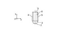
FIG. 1A is a front view of the
本実施形態の導光プリズム10は、6面体プリズムに接眼レンズ7を接合した構成である。6面体プリズムは、第1光学面1と、第2光学面2と、第3光学面3と、第4光学面4と、第5光学面5と第6光学面6とから成る。そして、画像光の射出部分に、接眼レンズ7が接合されている。 The
第1光学面1は、表示素子21からの画像光が入射する入射面である。第2光学面2と、第3光学面3とは、6面体における対向面であり、互いに略平行な面を構成している。また、第4光学面4と第5光学面5とは、6面体における対向面である。第6光学面6は、導光した画像光を反射する。第6光学面6により、反射された画像光は、接眼レンズ7により、不図示の使用者の瞳孔へ向けて射出される。 The first
さらに、図2を参照して、説明を続ける。図2は、本実施形態の導光プリズム10の斜視構成を示している。なお、図2において、接眼レンズ7の記載は省略する。 Furthermore, description is continued with reference to FIG. FIG. 2 shows a perspective configuration of the
上述したように、導光プリズム10は、表示素子21からの画像光が入射する入射面である第1光学面1と、第1光学面1から入射した画像光の光路を取り囲むように配置された少なくとも4つの側面である、第2光学面2と、第3光学面3と、第4光学面4と、第5光学面5とを有する。反射面である第6光学面6は、少なくとも4つの側面、即ち第2光学面2と、第3光学面3と、第4光学面4と、第5光学面5により取り囲まれたプリズム内を導光された画像光を反射させる。射出面である接眼レンズ7は、第6光学面6(反射面)で反射された画像光を、不図示の使用者の眼球に向けて射出する。
少なくとも4つの側面は、2組の互いに対向する2つの側面を有する。一組の対向する側面は、第2光学面と第3光学面である。他の一組の対向する側面は、第4光学面4と第5光学面5である。
そして、2組の互いに対向する2つの側面のうち一組である第4光学面4と第5光学面5は、画像光の入射光軸AX1を含み、入射光軸AX1と第6光学面6(反射面)の反射光軸AX2とがなす面S1と垂直な面S2において第1光学面1から第6光学面6に向かって先細りに傾斜している。かつ、第4光学面4と第5光学面5とは、入射光軸AX1に垂直な面S3において第2光学面2から第3光学面3に向かって先細りに傾斜している。さらに、反射面である第6光学面6は、矩形形状である。As described above, the
The at least four side surfaces have two sets of two opposite side surfaces. One set of opposing side surfaces is a second optical surface and a third optical surface. Another set of opposing side surfaces is a fourth
The fourth
2組の互いに対向する2つの側面のうち一組である第4光学面4と第5光学面5とは、対向する2つの側面の間隔が第1光学面1(入射面)側から第6光学面6(反射面)側にかけて狭くなる第1のテーパー構造を有する。言い換えると、第4光学面4と第5光学面5とは、対向する2つの側面の距離が入射面から反射面側にかけて短くなるテーパー構造を有する。
また、対向する2つの側面である第4光学面4と第5光学面5とは、対向する2つの側面の間隔が第2光学面2側から第3光学面3側にかけて狭くなる第2のテーパー構造を有する。言い換えると、第4光学面4と第5光学面5とは、第2光学面2側から第3光学面3側にかけて距離が短くなるテーパー構造を有する。The fourth
In addition, the fourth
具体的には、図1A、図1Cに示すように、第4光学面4と第5光学面5との面間隔が画素像高の射出側に向かって小さくなる、いわゆるハの字型の構成を有する。
また、第1光学面1の形状は、図1Dに示すように、y軸の正方向に向かって狭くなる、いわゆるハの字型の構成を有する。Specifically, as shown in FIGS. 1A and 1C, a so-called C-shaped configuration in which the distance between the fourth
Further, as shown in FIG. 1D, the first
ここで、第1のテーパー構造の傾斜角α(図1C)は、第2のテーパー構造の傾斜角β(図1D)より小さいことが望ましい。この条件を満たすことで、全反射条件を満たしやすくなる。 Here, the inclination angle α (FIG. 1C) of the first taper structure is preferably smaller than the inclination angle β (FIG. 1D) of the second taper structure. Satisfying this condition makes it easier to satisfy the total reflection condition.
導光プリズム10の形状が、四角柱のロッドプリズムの場合、使用者が観察する正規像の周囲に側面での意図しない反射に起因するゴーストを生じてしまう。本実施形態のように、2方向において、第1のテーパー構造と、第2のテーパー構造とを有することにより、ゴーストを正規像から遠ざけることができる。 When the shape of the
さらに、効率良くゴーストを低減するために、導光プリズム10の入射面である第1光学面1の近傍の側面の表面に、シボ加工を施すこと、溝を形成することもできる。 Furthermore, in order to reduce ghosts efficiently, the surface of the side surface in the vicinity of the first
なお、テーパーを設ける面は、これに限られず、例えば、第2光学面2と、第3光学面3との距離(面間隔)を、反射面に向かって小さくなるように面を傾斜させても良い。 In addition, the surface which provides a taper is not restricted to this, For example, a surface is inclined so that the distance (surface interval) of the 2nd
さらに、第1のテーパー構造の傾斜角をα(図1C)、第2のテーパー構造の傾斜角をβ(図1D)、画像光の反射面への入射光軸と反射部の法線とがなす角をγ(図1B)と、それぞれしたとき、以下の条件式(1)を満足することが望ましい。
tanγ=tanβ/tanα (1)Furthermore, the inclination angle of the first taper structure is α (FIG. 1C), the inclination angle of the second taper structure is β (FIG. 1D), and the optical axis incident on the reflection surface of the image light and the normal line of the reflection portion are When the angle formed is γ (FIG. 1B), it is desirable that the following conditional expression (1) is satisfied.
tan γ = tan β / tan α (1)
条件式(1)を満足することにより、反射面である第6光学面6の形状を矩形形状とすることができる。表示素子21の画像表示領域は、矩形形状である。このため、第6光学面6の形状を矩形形状とすることで、使用者は、導光プリズム10のサイズを極力小さくしつつ、矩形形状の有効光束を観察することができる。 When the conditional expression (1) is satisfied, the shape of the sixth
また、本発明の好ましい態様によれば、反射面である第6光学面6の長手方向の長さをdとしたとき、
以下の条件式(2)を満足することが望ましい。
d×sinγ×tanα=d×cosγ×tanβ (2)According to a preferred aspect of the present invention, when the length in the longitudinal direction of the sixth
It is desirable to satisfy the following conditional expression (2).
d × sin γ × tan α = d × cos γ × tan β (2)
条件式(2)を満足することでも、第6光学面6(反射面)を矩形形状とすることができる。 Satisfying conditional expression (2) also makes it possible to make the sixth optical surface 6 (reflection surface) rectangular.
次に、本実施形態に係る導光プリズム10の具体的な数値例を示す。ここでは第1のテーパー構造が、第4光学面4、および、第5光学面5の一部に形成される例で説明する。図1Aに示すように、第2光学面2側において、第1光学面1近傍における第4光学面4と第5光学面5との距離を4.00mm、第6光学面6近傍における第4光学面4と第5光学面5との距離を3.00mmとし、図1Bに示すように、第4光学面4、および第5光学面5の第1のテーパー構造部分の長さを25.00mmとした場合、第1のテーパー構造の傾斜角αは、0.02度となる。 Next, specific numerical examples of the
さらに、図1Dに示すように第1光学面1のy方向の長さを6.00mm、第3光学面3側において、第1光学面1近傍における第4光学面4と第5光学面5との距離を3.80mmとした場合、第2のテーパー構造の傾斜角βは、0.0167度となる。
このとき、画像光の第6光学面6(反射面)への入射光軸AX1と反射部の法線とがなす角γは、40.0度である。Further, as shown in FIG. 1D, the length of the first
At this time, the angle γ formed by the optical axis AX1 incident on the sixth optical surface 6 (reflection surface) of the image light and the normal line of the reflection portion is 40.0 degrees.
なお、第2のテーパー構造の傾斜角βは、0.01度〜1.5度の範囲が好ましい。傾斜角βを、この範囲とすることで、第6光学面6(反射面)の形状を、ほぼ矩形形状とすることができる。 The inclination angle β of the second taper structure is preferably in the range of 0.01 degrees to 1.5 degrees. By setting the inclination angle β within this range, the shape of the sixth optical surface 6 (reflection surface) can be made substantially rectangular.
(第2実施形態)
次に、実施形態1の導光プリズム10を有する頭部装着型映像表示装置について説明する。(Second Embodiment)
Next, a head-mounted image display apparatus having the
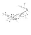
図3は、頭部装着型映像表示装置20の概略構成を示す。本体ユニット22と光学ユニット27とを有し、一般的な眼鏡26と共に用いる構成である。 FIG. 3 shows a schematic configuration of the head-mounted
本体ユニット22は、内部に液晶パネル或は有機EL等の表示素子21を有し、その他不図示の表示素子駆動デバイス等を備え、眼鏡26のツル25に固定される。 The
光学ユニット27は上述の導光プリズム10を内部に含み、本体ユニット22から独立して構成している。ここで、光学ユニット27は、上述の実施形態1における導光プリズム10を、一体成型された光学部材及び外装ケースなどによって格納したものを用いることができる。なお、光学ユニット27は、保持部材23を介してヨロイ24に固定される。 The
本実施形態に係る頭部装着型映像表示装置20では、導光プリズム10の内部を導光することにより、視界の邪魔にならない部分に表示素子21を配置することができる。 In the head-mounted
本実施形態の頭部装着型映像表示装置20によれば、使用者の瞳孔に導かれるゴーストを抑制し、かつ、使用者の瞳孔に矩形の画像光を導くことができる。 According to the head-mounted
なお、図3に示される構成では、本体ユニット22と光学ユニット27とが分離しているので、眼鏡26のツル25を折り畳んだときに本体ユニット22が連動して折り畳むことができる構成である。 In the configuration shown in FIG. 3, the
以上のように、本発明は、使用者の瞳孔に導かれるゴーストを抑制し、かつ、使用者の瞳孔に矩形の画像光を導くことができる導光プリズム及びこれを有する頭部装着型映像表示装置に有用である。 As described above, the present invention suppresses a ghost guided to the user's pupil and can guide a rectangular image light to the user's pupil, and a head-mounted image display having the same. Useful for equipment.
1 第1光学面(入射面)
2 第2光学面
3 第3光学面
4 第4光学面
5 第5光学面
6 第6光学面(反射面)
7 接眼レンズ
10 導光プリズム
20 頭部装着型映像表示装置
21 表示素子
22 本体ユニット
23 保持部材
24 ヨロイ
25 ツル
26 眼鏡
27 光学ユニット
AX1 入射光軸
AX2 反射光軸
α 第1のテーパー構造の傾斜角
β 第2のテーパー構造の傾斜角
γ 画像光の反射面への入射光軸と反射部の法線とがなす角1 First optical surface (incident surface)
2 2nd
DESCRIPTION OF
Claims (6)
Translated fromJapanese前記入射面から入射した前記画像光の光路を取り囲むように配置された少なくとも4つの側面と、
前記入射面から入射し、前記光路を導光された前記画像光を反射させる反射面と、
前記反射面で反射された前記画像光を、使用者の眼球に向けて射出する射出面と、
を有し、
前記少なくとも4つの側面は、2組の互いに対向する2つの側面を有し、
前記2組の互いに対向する2つの側面のうち一組は、前記画像光の入射光軸を含み、前記入射光軸と前記反射面の反射光軸とがなす面と垂直な面において傾斜し、かつ、前記入射光軸に垂直な面において傾斜しており、
前記反射面は、矩形形状であることを特徴とする導光プリズム。An incident surface on which image light from the display element is incident;
At least four side surfaces disposed so as to surround the optical path of the image light incident from the incident surface;
A reflective surface that reflects the image light incident from the incident surface and guided through the optical path;
An emission surface for emitting the image light reflected by the reflection surface toward the user's eyeball;
Have
The at least four sides have two sets of two opposite sides;
One of the two sets of two side surfaces facing each other includes an incident optical axis of the image light, and is inclined in a plane perpendicular to a plane formed by the incident optical axis and the reflected optical axis of the reflecting surface; And is inclined in a plane perpendicular to the incident optical axis,
The light guide prism, wherein the reflection surface has a rectangular shape.
前記対向する2つの側面の距離が前記射出面側から前記射出面から遠ざかる方向にかけて短くなる第2のテーパー構造と、
を有することを特徴とする請求項1に記載の導光プリズム。One of the two sets of the two side surfaces facing each other is such that the distance between the two side surfaces facing each other is short from the incident surface side to the reflection surface side when the user is observing the image light. A first taper structure comprising:
A second taper structure in which the distance between the two opposing side surfaces becomes shorter from the exit surface side in a direction away from the exit surface;
The light guide prism according to claim 1, comprising:
前記第2のテーパー構造の傾斜角をβ、
前記画像光の前記反射面への入射光軸と前記反射部の法線とがなす角をγと、それぞれしたとき、以下の条件式(1)を満足することを特徴とする請求項2または3に記載の導光プリズム。
tanγ=tanβ/tanα (1)The inclination angle of the first tapered structure is α,
The inclination angle of the second tapered structure is β,
The following conditional expression (1) is satisfied, where γ is an angle formed by an optical axis incident on the reflecting surface of the image light and a normal line of the reflecting portion: 3. The light guide prism according to 3.
tan γ = tan β / tan α (1)
以下の条件式(2)を満足することを特徴とする請求項4に記載の導光プリズム。
d×sinγ×tanα=d×cosγ×tanβWhen the distance in the longitudinal direction of the reflecting surface is d,
The light guide prism according to claim 4, wherein the following conditional expression (2) is satisfied.
d × sin γ × tan α = d × cos γ × tan β
前記表示素子からの画像光を使用者の瞳孔方向へ導く導光プリズムと、を有し、
前記導光プリズムは請求項1〜5のいずれか1項に記載の導光プリズムであることを特徴とする頭部装着型映像表示装置。
A display element for displaying an image;
A light guide prism that guides image light from the display element toward the pupil of the user,
The head-mounted image display device according to claim 1, wherein the light guide prism is the light guide prism according to claim 1.
Applications Claiming Priority (1)
| Application Number | Priority Date | Filing Date | Title |
|---|---|---|---|
| PCT/JP2015/064161WO2016185535A1 (en) | 2015-05-18 | 2015-05-18 | Light guide prism and head-mounted video display device having same |
Publications (1)
| Publication Number | Publication Date |
|---|---|
| JPWO2016185535A1true JPWO2016185535A1 (en) | 2018-03-01 |
Family
ID=57319612
Family Applications (1)
| Application Number | Title | Priority Date | Filing Date |
|---|---|---|---|
| JP2017518643APendingJPWO2016185535A1 (en) | 2015-05-18 | 2015-05-18 | Light guide prism and head-mounted image display apparatus having the same |
Country Status (3)
| Country | Link |
|---|---|
| US (1) | US10585216B2 (en) |
| JP (1) | JPWO2016185535A1 (en) |
| WO (1) | WO2016185535A1 (en) |
Families Citing this family (1)
| Publication number | Priority date | Publication date | Assignee | Title |
|---|---|---|---|---|
| JP6697253B2 (en)* | 2015-12-17 | 2020-05-20 | コピン コーポレーション | Wearable image display device and eyepiece optical system |
Citations (3)
| Publication number | Priority date | Publication date | Assignee | Title |
|---|---|---|---|---|
| JP2010232718A (en)* | 2009-03-25 | 2010-10-14 | Olympus Corp | Head-mounted image display apparatus |
| JP2012203113A (en)* | 2011-03-24 | 2012-10-22 | Olympus Corp | Head-mounted display device |
| JP2013080039A (en)* | 2011-10-03 | 2013-05-02 | Seiko Epson Corp | Virtual image display device and method for manufacturing the same |
Family Cites Families (3)
| Publication number | Priority date | Publication date | Assignee | Title |
|---|---|---|---|---|
| EP1757974B1 (en)* | 2004-05-17 | 2012-08-29 | Olympus Corporation | Head-mounted type image display device |
| JP5389492B2 (en) | 2009-03-25 | 2014-01-15 | オリンパス株式会社 | Head-mounted image display device |
| JP6697253B2 (en)* | 2015-12-17 | 2020-05-20 | コピン コーポレーション | Wearable image display device and eyepiece optical system |
- 2015
- 2015-05-18WOPCT/JP2015/064161patent/WO2016185535A1/ennot_activeCeased
- 2015-05-18JPJP2017518643Apatent/JPWO2016185535A1/enactivePending
- 2017
- 2017-11-16USUS15/814,472patent/US10585216B2/ennot_activeExpired - Fee Related
Patent Citations (3)
| Publication number | Priority date | Publication date | Assignee | Title |
|---|---|---|---|---|
| JP2010232718A (en)* | 2009-03-25 | 2010-10-14 | Olympus Corp | Head-mounted image display apparatus |
| JP2012203113A (en)* | 2011-03-24 | 2012-10-22 | Olympus Corp | Head-mounted display device |
| JP2013080039A (en)* | 2011-10-03 | 2013-05-02 | Seiko Epson Corp | Virtual image display device and method for manufacturing the same |
Also Published As
| Publication number | Publication date |
|---|---|
| WO2016185535A1 (en) | 2016-11-24 |
| US20180074235A1 (en) | 2018-03-15 |
| US10585216B2 (en) | 2020-03-10 |
Similar Documents
| Publication | Publication Date | Title |
|---|---|---|
| JP5389492B2 (en) | Head-mounted image display device | |
| JP5698578B2 (en) | Head-mounted display device | |
| US9726892B2 (en) | Light guide prism and image display apparatus | |
| JP6218649B2 (en) | Virtual image observation optical system and light guide prism | |
| US20170010473A1 (en) | Projection apparatus | |
| JP5496030B2 (en) | Head-mounted image display device | |
| US10168454B2 (en) | Head-mounted display device | |
| KR102657863B1 (en) | virtual image display device | |
| JP2017120298A (en) | Virtual image display device | |
| US11630305B2 (en) | Attachable image display device and ocular optical system | |
| JP6657943B2 (en) | Light guide and virtual image display | |
| JP6184370B2 (en) | Light guide prism and image display device | |
| JP5530575B1 (en) | Light guide prism and image display device | |
| JPWO2016185535A1 (en) | Light guide prism and head-mounted image display apparatus having the same | |
| JP6270569B2 (en) | Virtual image observation optical system and virtual image observation apparatus | |
| WO2017109857A1 (en) | Ocular projection optical device | |
| JP6293773B2 (en) | Light guide prism | |
| JP6238923B2 (en) | Light guide prism and image display device | |
| JP6625681B2 (en) | Head mounted display | |
| JP6238801B2 (en) | Virtual image observation optical system and virtual image observation apparatus |
Legal Events
| Date | Code | Title | Description |
|---|---|---|---|
| A621 | Written request for application examination | Free format text:JAPANESE INTERMEDIATE CODE: A621 Effective date:20180426 | |
| RD04 | Notification of resignation of power of attorney | Free format text:JAPANESE INTERMEDIATE CODE: A7424 Effective date:20190220 | |
| A131 | Notification of reasons for refusal | Free format text:JAPANESE INTERMEDIATE CODE: A131 Effective date:20190424 | |
| A02 | Decision of refusal | Free format text:JAPANESE INTERMEDIATE CODE: A02 Effective date:20191017 |