JPWO2016111226A1 - Fine particles, anti-counterfeit ink, anti-counterfeit toner, anti-counterfeit sheet, anti-counterfeit medium, and recorded information reader - Google Patents
Fine particles, anti-counterfeit ink, anti-counterfeit toner, anti-counterfeit sheet, anti-counterfeit medium, and recorded information readerDownload PDFInfo
- Publication number
- JPWO2016111226A1 JPWO2016111226A1JP2016568350AJP2016568350AJPWO2016111226A1JP WO2016111226 A1JPWO2016111226 A1JP WO2016111226A1JP 2016568350 AJP2016568350 AJP 2016568350AJP 2016568350 AJP2016568350 AJP 2016568350AJP WO2016111226 A1JPWO2016111226 A1JP WO2016111226A1
- Authority
- JP
- Japan
- Prior art keywords
- fine particles
- counterfeit
- fine particle
- code
- information
- Prior art date
- Legal status (The legal status is an assumption and is not a legal conclusion. Google has not performed a legal analysis and makes no representation as to the accuracy of the status listed.)
- Pending
Links
Images


Classifications
- B—PERFORMING OPERATIONS; TRANSPORTING
- B42—BOOKBINDING; ALBUMS; FILES; SPECIAL PRINTED MATTER
- B42D—BOOKS; BOOK COVERS; LOOSE LEAVES; PRINTED MATTER CHARACTERISED BY IDENTIFICATION OR SECURITY FEATURES; PRINTED MATTER OF SPECIAL FORMAT OR STYLE NOT OTHERWISE PROVIDED FOR; DEVICES FOR USE THEREWITH AND NOT OTHERWISE PROVIDED FOR; MOVABLE-STRIP WRITING OR READING APPARATUS
- B42D25/00—Information-bearing cards or sheet-like structures characterised by identification or security features; Manufacture thereof
- B42D25/30—Identification or security features, e.g. for preventing forgery
- B42D25/36—Identification or security features, e.g. for preventing forgery comprising special materials
- C—CHEMISTRY; METALLURGY
- C09—DYES; PAINTS; POLISHES; NATURAL RESINS; ADHESIVES; COMPOSITIONS NOT OTHERWISE PROVIDED FOR; APPLICATIONS OF MATERIALS NOT OTHERWISE PROVIDED FOR
- C09D—COATING COMPOSITIONS, e.g. PAINTS, VARNISHES OR LACQUERS; FILLING PASTES; CHEMICAL PAINT OR INK REMOVERS; INKS; CORRECTING FLUIDS; WOODSTAINS; PASTES OR SOLIDS FOR COLOURING OR PRINTING; USE OF MATERIALS THEREFOR
- C09D11/00—Inks
- C09D11/02—Printing inks
- C09D11/03—Printing inks characterised by features other than the chemical nature of the binder
- G—PHYSICS
- G03—PHOTOGRAPHY; CINEMATOGRAPHY; ANALOGOUS TECHNIQUES USING WAVES OTHER THAN OPTICAL WAVES; ELECTROGRAPHY; HOLOGRAPHY
- G03G—ELECTROGRAPHY; ELECTROPHOTOGRAPHY; MAGNETOGRAPHY
- G03G9/00—Developers
- G03G9/08—Developers with toner particles
- G—PHYSICS
- G06—COMPUTING OR CALCULATING; COUNTING
- G06K—GRAPHICAL DATA READING; PRESENTATION OF DATA; RECORD CARRIERS; HANDLING RECORD CARRIERS
- G06K19/00—Record carriers for use with machines and with at least a part designed to carry digital markings
- G06K19/06—Record carriers for use with machines and with at least a part designed to carry digital markings characterised by the kind of the digital marking, e.g. shape, nature, code
- G—PHYSICS
- G06—COMPUTING OR CALCULATING; COUNTING
- G06K—GRAPHICAL DATA READING; PRESENTATION OF DATA; RECORD CARRIERS; HANDLING RECORD CARRIERS
- G06K7/00—Methods or arrangements for sensing record carriers, e.g. for reading patterns
- G06K7/10—Methods or arrangements for sensing record carriers, e.g. for reading patterns by electromagnetic radiation, e.g. optical sensing; by corpuscular radiation
- G06K7/14—Methods or arrangements for sensing record carriers, e.g. for reading patterns by electromagnetic radiation, e.g. optical sensing; by corpuscular radiation using light without selection of wavelength, e.g. sensing reflected white light
Landscapes
- Physics & Mathematics (AREA)
- Engineering & Computer Science (AREA)
- General Physics & Mathematics (AREA)
- Chemical & Material Sciences (AREA)
- Theoretical Computer Science (AREA)
- Artificial Intelligence (AREA)
- General Chemical & Material Sciences (AREA)
- Toxicology (AREA)
- Electromagnetism (AREA)
- Computer Vision & Pattern Recognition (AREA)
- Health & Medical Sciences (AREA)
- Chemical Kinetics & Catalysis (AREA)
- General Health & Medical Sciences (AREA)
- Life Sciences & Earth Sciences (AREA)
- Materials Engineering (AREA)
- Wood Science & Technology (AREA)
- Organic Chemistry (AREA)
- Credit Cards Or The Like (AREA)
- Inks, Pencil-Leads, Or Crayons (AREA)
Abstract
Translated fromJapaneseDescription
Translated fromJapanese本発明は、微粒子による偽造防止技術に関する。 The present invention relates to a technique for preventing forgery by fine particles.
物品の偽造を防止するための偽造防止技術には、その用途から2つの側面が求められる。まず、一見するだけでは、その物品に偽造防止技術が付されていることを認識することができないこと、また、物品を使用する需要者が物品の安全性等の観点から正規品であることを確認する場合等に、容易に認証が行えることである。 The anti-counterfeit technology for preventing counterfeiting of articles requires two aspects from its application. First, at first glance, it cannot be recognized that the article has anti-counterfeiting technology, and that the consumer who uses the article is genuine from the viewpoint of the safety of the article. It is easy to authenticate when confirming.
現在、多用されている偽造防止技術として、目視で真贋判定可能な透かし技術やホログラム等が挙げられる。これらの技術では、目視で確認できることから容易に認証が行えるという利点を有するが、さらなる偽造防止効果の向上への要求から新たな偽造防止技術の開発が望まれていた。 Currently, anti-counterfeiting techniques that are widely used include a watermark technique and a hologram that can be visually checked for authenticity. These techniques have the advantage that authentication can be performed easily because they can be visually confirmed, but the development of a new anti-counterfeiting technique has been desired due to the demand for further improvement of the anti-counterfeiting effect.
新たな偽造防止技術として、タガント粒子(追跡用添加物)と呼ばれる微粒子を用い、ルーペ等の簡易的な拡大器具を使用して真贋判定を行う技術が提案されている。特に、出願人は、形状に基づいて識別可能であり、透明性を有し、樹脂製の材料を含む微粒子による偽造防止技術を開発している(特開2012−236369号公報参照)。 As a new anti-counterfeiting technology, a technology has been proposed in which fineness called taggant particles (tracking additives) is used and authenticity is determined using a simple magnifier such as a loupe. In particular, the applicant has developed a technique for preventing forgery using fine particles that are identifiable based on shape, have transparency, and contain a resin material (see JP 2012-236369 A).
上述した特開2012−236369号公報に記載の技術を利用することにより、ルーペ等の拡大器具を用いなければ、微粒子を容易に発見することが難しいため、模倣・複製される可能性はある程度低減されている。しかしながら、逆に、ルーペ等を見れば、視認可能であるため、用途によっては、十分に偽造防止効果を発揮しているとは言えない。 By using the technique described in Japanese Patent Application Laid-Open No. 2012-236369 described above, it is difficult to find fine particles without using a magnifier such as a magnifying glass. Has been. However, on the contrary, since it can be visually recognized by looking at a loupe or the like, it cannot be said that the anti-counterfeiting effect is sufficiently exhibited depending on the application.
そこで、本発明は、拡大器具を用いただけでは記録情報の識別が不能であって、拡大とともに所定の情報処理を行うことにより、記録情報を取得することが可能な微粒子、偽造防止用インク、偽造防止用トナー、偽造防止用シート、偽造防止媒体および記録情報読取装置を提供することを課題とする。 Accordingly, the present invention is not capable of identifying recorded information only by using a magnifying device, and is capable of acquiring recorded information by performing predetermined information processing together with enlargement, anti-counterfeit ink, forgery It is an object of the present invention to provide an anti-counterfeit toner, an anti-counterfeit sheet, an anti-counterfeit medium, and a recorded information reading device.
上記課題を解決するため、本発明の一態様では、拡大することにより形状を識別することが可能な微粒子であって、光学的に読取可能なコード情報に基づく形状を表現するように形成されていることを特徴とする微粒子を提供する。 In order to solve the above-described problem, in one embodiment of the present invention, fine particles that can be identified by being enlarged are formed to express a shape based on optically readable code information. Provided is a fine particle characterized by
本発明の一態様によれば、拡大することにより形状を識別することが可能な微粒子が、光学的に読取可能なコード体系に基づく形状を表現しているので、拡大器具を用いただけでは記録情報の識別を不能とし、表現された情報に対して情報処理を行って記録情報を取得させることが可能となる。 According to one aspect of the present invention, since the fine particles whose shape can be identified by enlarging express the shape based on the optically readable code system, the recorded information can be recorded only by using the enlarging instrument. And the recorded information can be acquired by performing information processing on the expressed information.
また、本発明の他の一態様では、前記光学的に読取可能なコード情報に基づく形状は、光学的に読取可能なコード情報を構成する各コード要素と、各コード要素を接続する接続部と、を有することを特徴とする。 Further, in another aspect of the present invention, the shape based on the optically readable code information includes each code element constituting the optically readable code information, and a connecting portion that connects each code element. It is characterized by having.
本発明の他の一態様によれば、光学的に読取可能なコード体系に基づく形状が、光学的に読取可能なコード体系を構成する各コード要素と、各コード要素を接続する接続部と、を有するので、本来各コード要素が分離しているコード体系であっても、分離することなく、1つの微粒子が所定の情報を保持することが可能となる。 According to another aspect of the present invention, the shape based on the optically readable code system has each code element constituting the optically readable code system, and a connection part that connects each code element, Therefore, even in a code system in which each code element is originally separated, one fine particle can hold predetermined information without being separated.
前記接続部は、第1方向に延在していてもよく、前記各コード要素は、前記第1方向に交差する第2方向に延在していてもよく、前記各コード要素の各一端は前記接続部に接続されていてもよい。 The connecting portion may extend in a first direction, each cord element may extend in a second direction intersecting the first direction, and each one end of each cord element may be You may be connected to the said connection part.
前記接続部は、一方向に延在するか、あるいは連続的または断続的に変化する方向に延在していてもよく、前記各コード要素は、前記接続部の延在方向に沿って、離隔して配置されていてもよい。 The connecting portion may extend in one direction, or may extend in a continuously or intermittently changing direction, and the cord elements may be separated from each other along the extending direction of the connecting portion. May be arranged.
前記接続部は、第1方向に延在していてもよく、前記各コード要素は、前記第1方向に交差する第2方向に延在していてもよく、前記各コード要素の各一端は前記接続部に接続されていてもよい。 The connecting portion may extend in a first direction, each cord element may extend in a second direction intersecting the first direction, and each one end of each cord element may be You may be connected to the said connection part.
前記各コード要素の前記第2方向の長さは同一であってもよく、前記コード情報は、前記第1方向に配置される前記各コード要素の数と、前記各コード要素の前記第1方向の幅と、前記第1方向に隣接する2つのコード要素間の隙間と、の少なくとも一つを可変調整することにより生成されてもよい。 The lengths of the code elements in the second direction may be the same, and the code information includes the number of the code elements arranged in the first direction and the first direction of the code elements. And at least one of a gap between two code elements adjacent in the first direction may be variably adjusted.
また、本発明の他の一態様では、前記微粒子を含有することを特徴とする偽造防止用インクを提供する。 In another embodiment of the present invention, an anti-counterfeit ink containing the fine particles is provided.
本発明の他の一態様によれば、偽造防止用インクが、本発明第1または第2の態様の微粒子を含有するので、高い偽造防止機能を有する偽造防止用インクを作製することが可能となる。 According to another aspect of the present invention, since the anti-counterfeit ink contains the fine particles according to the first or second aspect of the present invention, it is possible to produce an anti-counterfeit ink having a high anti-counterfeit function. Become.
また、本発明の他の一態様では、前記微粒子を含有することを特徴とする偽造防止用トナーを提供する。 In another embodiment of the present invention, there is provided a forgery-preventing toner comprising the fine particles.
本発明の他の一態様によれば、偽造防止用トナーが、本発明第1または第2の態様の微粒子を含有するので、高い偽造防止機能を有する偽造防止用トナーを作製することが可能となる。 According to another aspect of the present invention, since the anti-counterfeit toner contains the fine particles according to the first or second aspect of the present invention, it is possible to produce an anti-counterfeit toner having a high anti-counterfeit function. Become.
また、本発明の他の一態様では、前記微粒子が透明樹脂中に分散された微粒子含有層を有することを特徴とする偽造防止用シートを提供する。 According to another aspect of the present invention, there is provided a forgery-preventing sheet comprising a fine particle-containing layer in which the fine particles are dispersed in a transparent resin.
本発明の他の一態様によれば、偽造防止用シートが、本発明第1または第2の態様の微粒子が透明樹脂中に分散された微粒子含有層を有するので、高い偽造防止機能を有する偽造防止用シートを作製することが可能となる。 According to another aspect of the present invention, the anti-counterfeit sheet has a fine particle-containing layer in which the fine particles according to the first or second aspect of the present invention are dispersed in a transparent resin, and thus has a high anti-counterfeit function. It becomes possible to produce the sheet for prevention.
また、本発明の他の一態様では、前記微粒子または前記偽造防止用シートを有することを特徴とする偽造防止媒体を提供する。 In another aspect of the present invention, there is provided a forgery prevention medium comprising the fine particles or the forgery prevention sheet.
本発明の他の一態様によれば、偽造防止用シートが、本発明第1または第2の態様の微粒子または第5の態様の偽造防止用シートを有するので、秘匿性に優れる高い偽造防止機能を有することが可能であり、容易に真贋判定することが可能な偽造防止媒体を作製することが可能となる。 According to another aspect of the present invention, the anti-counterfeit sheet has the fine particles according to the first or second aspect of the present invention or the anti-counterfeit sheet according to the fifth aspect. Therefore, the anti-counterfeit function is excellent in confidentiality. It is possible to produce an anti-counterfeit medium that can easily determine the authenticity.
また、本発明の他の一態様では、拡大することにより形状を識別することが可能な微粒子であって、光学的に読取可能なコード情報に基づく形状を表現するように形成されている前記微粒子を撮像した撮像画像を取得する撮像手段と、前記撮像画像の一部を拡大した拡大画像を取得する画像拡大手段と、前記拡大画像中から前記微粒子に対応する微粒子部分を抽出し、抽出した前記微粒子部分から特徴部分を取得する特徴部分取得手段と、前記特徴部分に対して解析を行い記録された情報を取得する画像解析手段と、解析により得られた情報を出力する出力手段と、を有することを特徴とする微粒子の記録情報読取装置を提供する。 In another aspect of the present invention, the fine particles can be identified by enlarging the shape, and are formed so as to express the shape based on optically readable code information. Imaging means for acquiring a captured image obtained by imaging, image enlargement means for acquiring an enlarged image obtained by enlarging a part of the captured image, and extracting and extracting the fine particle portion corresponding to the fine particles from the enlarged image A feature portion acquiring means for acquiring a feature portion from the fine particle portion; an image analyzing means for analyzing the feature portion to acquire recorded information; and an output means for outputting information obtained by the analysis. There is provided a fine particle recording information reading device.
本発明の他の一態様によれば、記録情報読取装置が、前記微粒子を撮像して、撮像画像として取得する撮像手段と、撮像画像の一部を所定の倍率で拡大して拡大画像を取得する画像拡大手段と、拡大画像中から微粒子部分を抽出し、抽出した微粒子部分から接続部を除去して特徴部分を取得する特徴部分取得手段と、特徴部分に対して解析を行い記録された情報を取得する画像解析手段と、解析により得られた情報を出力する出力手段と、を有するので、目視では確認できない微粒子に向けて撮影行為を行うだけで、微粒子に記録された情報を取得することが可能となる。 According to another aspect of the present invention, the recorded information reading apparatus captures the fine particles and acquires the captured image as a captured image, and acquires a magnified image by enlarging a part of the captured image at a predetermined magnification. Image enlarging means, feature portion obtaining means for extracting the fine particle portion from the enlarged image, removing the connecting portion from the extracted fine particle portion to obtain the feature portion, and information recorded by analyzing the feature portion Since the image analysis means for obtaining the image and the output means for outputting the information obtained by the analysis are provided, the information recorded in the fine particles can be obtained only by performing a photographing action on the fine particles that cannot be visually confirmed. Is possible.
前記光学的に読取可能なコード情報に基づく形状は、光学的に読取可能なコード情報を構成する各コード要素と、各コード要素を接続する接続部と、を含んでいてもよく、前記特徴部分取得手段は、前記微粒子部分から前記接続部の画像を除去して、前記コード情報を含む前記特徴部分を取得してもよい。 The shape based on the optically readable code information may include each code element constituting the optically readable code information and a connection portion connecting each code element, and the characteristic portion The acquisition unit may acquire the feature portion including the code information by removing an image of the connection portion from the fine particle portion.
前記接続部は、第1方向に延在していてもよく、前記各コード要素は、前記第1方向に交差する第2方向に延在していてもよく、前記各コード要素の各一端は前記接続部に接続されていてもよく、前記特徴部分取得手段は、前記第1方向に配置される前記各コード要素の数と、前記各コード要素の前記第1方向の幅と、前記第1方向に隣接する2つのコード要素間の隙間と、の少なくとも一つにより、前記特徴部分に含まれる前記コード情報を識別してもよい。 The connecting portion may extend in a first direction, each cord element may extend in a second direction intersecting the first direction, and each one end of each cord element may be The characteristic portion acquisition means may be connected to the connection portion, and the characteristic portion acquisition means may include the number of the code elements arranged in the first direction, the width of the code elements in the first direction, and the first The code information included in the feature portion may be identified by at least one of a gap between two code elements adjacent in the direction.
本発明によれば、拡大器具を用いただけでは記録情報の識別を不能とし、拡大とともに所定の情報処理を行うことにより、記録情報を取得することが可能となる。 According to the present invention, it is possible to acquire the record information by making it impossible to identify the record information only by using the magnifying device and performing predetermined information processing together with the enlargement.
以下、本発明の好適な実施形態について、図面を参照して詳細に説明する。
<1.微粒子>
<1.1.微粒子の形状>
図1は、本発明の一実施形態に係る微粒子の形状を示す図である。図1(a)は平面図、図1(b)は、図1(a)のA方向から見た側面図、図1(c)は、図1(a)のB方向から見た側面図である。本発明の一実施形態に係る微粒子は、光学的に読取可能なコード情報に基づく形状を表現している。コード情報とは、文字、記号などの情報を一定の規則に従い変換したバーコードや、水平方向と垂直方向に情報を持つ二次元のコードである二次元コード等、情報を所定の形状に変換したものの総称である。本実施形態に係る微粒子10は、光学的に読取可能なコード情報として(一次元の)バーコードを採用した形態となっている。バーコードは、上下方向に延びる同一長さの複数のバーが左右方向に複数本並んでいることを特徴とする。通常のバーコードでは、バーの幅は様々であるが、図1では、図の簡略化のため、同一幅のバーを複数並べた状態としてある。DESCRIPTION OF EMBODIMENTS Hereinafter, preferred embodiments of the present invention will be described in detail with reference to the drawings.
<1. Fine particles>
<1.1. Shape of fine particles>
FIG. 1 is a diagram showing the shape of fine particles according to an embodiment of the present invention. 1A is a plan view, FIG. 1B is a side view seen from the direction A in FIG. 1A, and FIG. 1C is a side view seen from the direction B in FIG. 1A. It is. The fine particles according to an embodiment of the present invention express a shape based on optically readable code information. Code information is information that has been converted into a predetermined shape, such as a barcode that is converted from information such as characters and symbols according to certain rules, and a two-dimensional code that is a two-dimensional code having information in the horizontal and vertical directions. It is a general term for things. The
図1(a)に示す平面図において、1はコード要素であり、バーコードの各バーに相当する。微粒子10は、図1(a)に示すように、長さd2の9本のコード要素1が、1本の接続部2により接続された形態となっている。接続部2は、各コード要素1の一方の端部(図1(a)の下端)に形成されているため、図1(b)に示すように、A方向の側面から見ると、1本のバーとして見える。また、図1(c)に示すように、B方向の側面から見ると、1本のコード要素1のみが見えることになる。図1(a)の例では、接続部2は、第1方向(図示の水平方向)に延在している。各コード要素1は、第1方向に交差する第2方向(図示の垂直方向)に延在している。各コード要素1の各一端は、接続部2に接続されている。微粒子10に付与されるコード情報は、第1方向に配置される各コード要素1の数と、各コード要素1の第1方向の幅と、第1方向に隣接する2つのコード要素1間の隙間と、の少なくとも一つを可変調整することにより生成される。 In the plan view shown in FIG. 1A,
これにより、一つの微粒子10に、より多くの情報を付与することができる。また、微粒子10を透明樹脂等に分散させた場合であっても、微粒子10を構成する接続部2と各コード要素1の位置関係を一定に保持でき、微粒子10を解析することで、微粒子10に付与された情報を長期間にわたって安定して取得することができる。 Thereby, more information can be given to one
微粒子10の形状は、図1に示したものに限定されない。接続部22に接続された1以上のコード要素1を有していれば、微粒子10の具体的な形状は問わない。すなわち、微粒子10の接続部2は、一方向に延在するか、あるいは連続的または断続的に変化する方向に延在していればよい。微粒子10の各コード要素1は、接続部2の延在方向に沿って、離隔して配置されている。 The shape of the
図2(a)は第1変形例に係る微粒子10の形状を示す図、図2(b)は第2変形例に係る微粒子10の形状を示す図、図2(c)は第3変形例に係る微粒子10の形状を示す図である。 2A is a diagram showing the shape of the
第1変形例と第2変形例に係る微粒子10はいずれも、第1方向に延在する接続部2と、数字、記号、文字および絵画像の少なくとも一つの識別情報を含むコード要素1とを有する。より具体的には、第1変形例の各コード要素1は数字であり、第2変形例の各コード要素1は文字である。 Each of the
第3変形例に係る微粒子10は、円環状の接続部2と、数字、記号、文字および絵画像の少なくとも一つの識別情報を含むコード要素1とを有する。接続部2は、必ずしも円環状である必要はなく、延在方向が連続的または断続的に変化して閉空間を形成する任意の形状で構わない。図2(c)では、円環状の接続部2の内側に、周状に離隔して複数のコード要素1を配置しており、各コード要素1を接続部2によって取り囲んでいる。これにより、各コード要素1が接続部2によって保護されて、各コード要素1間の位置関係をより安定に保持しやすくなる。なお、各コード要素1間の位置関係の保持特性が図2(c)よりも劣化するおそれはあるが、円環状の接続部2の外側に、周状に離隔して複数のコード要素1を配置してもよい。 The
図1の微粒子10は、接続部2に接続される各コード要素1の数や間隔等を調整することで、複数のコード情報を生成していたが、図2(a)〜図2(c)の微粒子10は、各コード要素1自体が識別情報の一部となりうる。なお、秘匿性を高めるには、接続部2に接続された各コード要素1の数字、記号、文字および絵画像などの組合せがコード情報を表すようにしてもよい。図2(a)〜図2(c)の微粒子10の場合、後述する撮像手段等を利用して、微粒子10の接続部2に接続された複数のコード要素1の情報を一体として読み取ることができる。 The
<1.2.微粒子の大きさ>
微粒子の大きさとしては、肉眼で視認困難な大きさである必要がある。具体的には、300μm以下であることが好ましく、250μm以下であることがより好ましい。微粒子が大きすぎると、目視で観察可能となり、偽造防止効果が低下するおそれがあるからである。また、微粒子の大きさは、後述する記録情報読取装置により撮像して識別可能な程度とする必要があるため、50μm以上であることが好ましい。<1.2. Size of fine particles>
The size of the fine particles needs to be difficult to visually recognize with the naked eye. Specifically, it is preferably 300 μm or less, and more preferably 250 μm or less. This is because if the fine particles are too large, they can be visually observed and the forgery prevention effect may be reduced. The size of the fine particles is preferably 50 μm or more because the size of the fine particles needs to be determined so that they can be identified by being picked up by a recording information reader described later.
図1(a)に示した微粒子10の例では、d1が300μm、d2が100μm程度となっている。図1(b)、図1(c)の図面上下方向で示される微粒子10の厚さは、20μmとなっている。また、図1(a)に示した各コード要素1の平面方向の幅は10〜20μm程度、コード要素1間の隙間は10〜20μm程度となっている。 In the example of the
<1.3.微粒子の材質>
本発明の一実施形態に係る微粒子は、樹脂製の材料を含むものである。以下、一実施形態に係る微粒子に用いられる材料について説明する。樹脂製の材料としては、上述した微粒子を作製できるものであれば特に限定されるものではなく、例えば、エポキシアクリレート樹脂、ウレタンアクリレート樹脂、ポリアミック酸樹脂、ポリイミド樹脂等の光硬化性樹脂材料、不飽和ポリエステル樹脂、アクリルウレタン樹脂、エポキシ変性アクリル樹脂、エポキシ変性不飽和ポリエステル樹脂、アルキド樹脂、フェノール樹脂等の熱硬化性樹脂材料、アクリル酸エステル樹脂、アクリルアミド樹脂、ニトロセルロース樹脂、ポリスチレン樹脂等の熱可塑性樹脂材料、感光性樹脂材料を挙げることができる。また、感光性樹脂材料としては、ポジ型感光性樹脂およびネガ型感光性樹脂のいずれも用いることができる。上述した材料の中でも、光硬化性樹脂材料、感光性樹脂材料が好ましく、特に光硬化性樹脂材料が好ましい。光硬化性樹脂材料を用いることにより、形状に基づいて識別することが可能な識別情報を有する微粒子を、高精細に形成することが可能となるからである。<1.3. Fine particle material>
The fine particles according to one embodiment of the present invention include a resin material. Hereinafter, materials used for the fine particles according to the embodiment will be described. The resin material is not particularly limited as long as the above-described fine particles can be produced. For example, photocurable resin materials such as epoxy acrylate resin, urethane acrylate resin, polyamic acid resin, polyimide resin, Thermosetting resin materials such as saturated polyester resin, acrylic urethane resin, epoxy-modified acrylic resin, epoxy-modified unsaturated polyester resin, alkyd resin, phenol resin, heat of acrylic ester resin, acrylamide resin, nitrocellulose resin, polystyrene resin, etc. Examples thereof include a plastic resin material and a photosensitive resin material. Further, as the photosensitive resin material, either a positive photosensitive resin or a negative photosensitive resin can be used. Among the materials described above, a photocurable resin material and a photosensitive resin material are preferable, and a photocurable resin material is particularly preferable. This is because by using the photocurable resin material, fine particles having identification information that can be identified based on the shape can be formed with high definition.
本発明の一実施形態に係る微粒子の屈折率は、上記微粒子を構成する材料の種類および配合量等によって異なるものであり、一実施形態においては、微粒子が所望の偽造防止機能を実現できる程度であれば特に限定されるものではない。なお、一実施形態に係る微粒子の屈折率は、上記微粒子の用途等に応じて適宜調整されるものである。 The refractive index of the fine particles according to one embodiment of the present invention varies depending on the type and blending amount of the material constituting the fine particles, and in one embodiment, the fine particles can realize a desired anti-counterfeit function. There is no particular limitation as long as it is present. In addition, the refractive index of the fine particles according to an embodiment is appropriately adjusted according to the use of the fine particles.
<1.3.1.機能性材料>
本発明の一実施形態に用いられる樹脂製の材料は、機能性材料を含有することが好ましい。微粒子の存在を明示することができるため、真贋判定を容易に行うことができるからである。機能性材料としては、紫外線発光材料、赤外線発光材料、赤外線反射材料、赤外線吸収材料、量子ドット材料、磁性材料、顔料や染料等の着色材料等が挙げられる。中でも、紫外線発光材料、赤外線発光材料、赤外線反射材料、赤外線吸収材料等が好適に用いられる。拡大することにより識別が可能であり、また発光、光の反射および吸収による識別が可能であることから、真贋判定が容易となるからである。さらに、本発明の一実施形態に係る微粒子が透明性を有する場合、例えば透明樹脂中に分散させた微粒子含有層を形成した場合、微粒子は樹脂製の材料を含むので、微粒子と透明樹脂との屈折率の差が小さいと、微粒子と透明樹脂の界面が見えにくくなり、微粒子の識別情報を認識することが困難となってしまう場合がある。このような場合においても、上記微粒子が機能性材料を含有することにより、識別情報を認識することが可能となる。以下、各機能性材料について説明する。<1.3.1. Functional materials>
The resin material used in one embodiment of the present invention preferably contains a functional material. This is because the presence of the fine particles can be clearly indicated, so that the authenticity determination can be easily performed. Examples of the functional material include ultraviolet light emitting materials, infrared light emitting materials, infrared reflecting materials, infrared absorbing materials, quantum dot materials, magnetic materials, and coloring materials such as pigments and dyes. Among these, an ultraviolet light emitting material, an infrared light emitting material, an infrared reflecting material, an infrared absorbing material and the like are preferably used. This is because identification can be performed by enlarging, and identification by light emission, light reflection and absorption is possible, and authentication can be easily determined. Furthermore, when the fine particles according to an embodiment of the present invention have transparency, for example, when a fine particle-containing layer dispersed in a transparent resin is formed, the fine particles include a resin material. If the difference in refractive index is small, the interface between the fine particles and the transparent resin becomes difficult to see, and it may be difficult to recognize the identification information of the fine particles. Even in such a case, the identification information can be recognized when the fine particles contain the functional material. Hereinafter, each functional material will be described.
<1.3.1.1.紫外線発光材料>
紫外線発光材料としては、紫外線の吸収により蛍光発光する材料を用いることができる。紫外線発光材料は、短波長域(約200nm〜300nm)の吸収により発光するもの、および、長波長域(約300nm〜400nm)の吸収により発光するもののいずれも使用することができる。この紫外線発光材料は、紫外線により励起され、これよりも低いエネルギー準位に戻るときに発するスペクトルのピークが青、緑、赤等の波長域にあるものであり、目的に応じて適宜選択することができる。具体例としては、Ca2B5O9Cl:Eu2+、CaWO4、ZnO:Zn、Zn2SiO4:Mn、Y2O2S:Eu、ZnS:Ag、YVO4:Eu、Y2O3:Eu、Gd2O2S:Tb、La2O2S:Tb、Y3Al5O12:Ce、Sr5(PO4)3Cl:Eu、3(Ba,Mg)O・8Al2O3:Eu、Zn2GeO4:Mn、Y(P,V)O4:Eu、0.5MgF2・3.5MgO・GeO2:Mn、ZnS:Cu、ZnS:Mn等が挙げられる。これらは単独で用いてもよく2種類以上で用いてもよい。なお、上記紫外線発光材料は、その組成を、主成分と付活剤または発光中心とを「:」で繋いで表記している。<1.3.1.1. Ultraviolet light emitting material>
As the ultraviolet light emitting material, a material that emits fluorescence by absorbing ultraviolet light can be used. As the ultraviolet light-emitting material, either a material that emits light by absorption in a short wavelength region (about 200 nm to 300 nm) or a material that emits light by absorption in a long wavelength region (about 300 nm to 400 nm) can be used. This ultraviolet light emitting material is excited by ultraviolet light and has a spectrum peak emitted when returning to a lower energy level in the wavelength range such as blue, green, red, etc., and should be selected appropriately according to the purpose. Can do. As specific examples, Ca2 B5 O9 Cl: Eu2+ , CaWO4 , ZnO: Zn, Zn2 SiO4 : Mn, Y2 O2 S: Eu, ZnS: Ag, YVO4 : Eu, Y2 O3 : Eu, Gd2 O2 S: Tb, La2 O2 S: Tb, Y3 Al5 O12 : Ce, Sr5 (PO4 )3 Cl: Eu, 3 (Ba, Mg) O · 8Al2 O3 : Eu, Zn2 GeO4 : Mn, Y (P, V) O4 : Eu, 0.5MgF2 · 3.5MgO · GeO2 : Mn, ZnS: Cu, ZnS: Mn, and the like. These may be used alone or in combination of two or more. Note that the composition of the ultraviolet light-emitting material is expressed by connecting the main component and the activator or the light emission center with “:”.
微粒子中の紫外線発光材料の含有量としては、発光による識別が可能であれば特に限定されるものではなく、具体的には、1質量%〜50質量%程度とすることができる。 The content of the ultraviolet light emitting material in the fine particles is not particularly limited as long as it can be identified by light emission, and specifically, it can be about 1% by mass to 50% by mass.
<1.3.1.2.赤外線発光材料>
本発明の一実施形態に用いられる赤外線発光材料としては、赤外線の吸収により蛍光発光する材料を用いることができる。赤外線発光材料は、赤外線(約800nm〜1200nm)で励起され、可視光(約400nm〜800nm)を発光するものであり、目的に応じて適宜選択することができる。具体例としてはYF3:Yb+Er、YF3Yb+Tm、BaFCl:Yb+Er等が挙げられる。なお、上記赤外線発光材料は、その組成を、主成分と付活剤または発光中心とを「:」で繋いで表記している。<1.3.1.2. Infrared light emitting material>
As the infrared light emitting material used in one embodiment of the present invention, a material that emits fluorescence by absorbing infrared light can be used. The infrared light emitting material is excited by infrared light (about 800 nm to 1200 nm) and emits visible light (about 400 nm to 800 nm), and can be appropriately selected depending on the purpose. Specific examples include YF3 : Yb + Er, YF3 Yb + Tm, BaFCl: Yb + Er, and the like. In addition, the said infrared luminescent material has described the composition by connecting a main component, an activator, or a luminescent center by ":".
微粒子中の赤外線発光材料の含有量としては、発光による識別が可能であれば特に限定されるものではなく、具体的には、1質量%〜50質量%程度とすることができる。 The content of the infrared light emitting material in the fine particles is not particularly limited as long as it can be discriminated by light emission, and can be specifically about 1% by mass to 50% by mass.
<1.3.1.3.赤外線反射材料>
赤外線反射材料としては、赤外線に対して波長選択反射性を有する材料を用いることができ、例えば、多層構造材料、赤外線反射顔料、コレステリック構造を有する液晶材料等を挙げることができる。赤外線反射材料が反射する赤外線の波長は特に限定されないが、通常、800nm〜2500nmである。<1.3.1.3. Infrared reflective material>
As the infrared reflecting material, a material having wavelength selective reflectivity with respect to infrared rays can be used, and examples thereof include a multilayer structure material, an infrared reflecting pigment, and a liquid crystal material having a cholesteric structure. The wavelength of infrared rays reflected by the infrared reflecting material is not particularly limited, but is usually 800 nm to 2500 nm.
多層構造材料としては、赤外線を反射するような間隔で形成された赤外線反射面を有する層(赤外線反射層)で構成された多層構造材料を挙げることができる。多層構造材料は、各層(赤外線反射層)のBragg反射によって特定波長の赤外線を反射するものである。具体的には、コレステリック液晶の架橋体のような固定化されたコレステリック構造を有する多層液晶材料を用いて、赤外線反射層を形成することができる。 Examples of the multilayer structure material include a multilayer structure material composed of a layer having an infrared reflection surface (infrared reflection layer) formed at intervals that reflect infrared rays. The multilayer structure material reflects infrared light having a specific wavelength by Bragg reflection of each layer (infrared reflective layer). Specifically, the infrared reflective layer can be formed using a multilayer liquid crystal material having a fixed cholesteric structure such as a crosslinked cholesteric liquid crystal.
赤外線反射顔料は、赤外線反射材料の粉末や粒子が用いられ、無機系顔料および有機系顔料のいずれも用いることができる。無機系顔料としては、例えば、酸化チタン(TiO2)、酸化亜鉛、硫化亜鉛、鉛白、酸化アンチモン、酸化ジルコニウム、酸化インジウム錫(ITO)、アンチモンドープ酸化錫(ATO)等の複合金属酸化物、アルミニウム、金、銅等の金属が挙げられる。また、無機系顔料として、特開2004−4840号公報に記載の、天然または合成雲母、別の葉状珪酸塩、ガラス薄片、薄片状二酸化珪素または酸化アルミニウム等の透明支持材料と、金属酸化物の被覆とからなる干渉顔料等も用いることができる。一方、有機系顔料としては、例えば、特開2005−330466号公報および特開2002−249676号公報に記載されている顔料が挙げられ、アゾ系、アンスラキノン系、フタロシアニン系、ペリノン・ペリレン系、インジゴ・チオインジゴ系、ジオキサジン系、キナクリドン系、イソインドリノン系、イソインドリン系、ジケトピロロピロール系、アゾメチン系およびアゾメチンアゾ系の有機色素を用いることができる。As the infrared reflective pigment, powder and particles of an infrared reflective material are used, and any of inorganic pigments and organic pigments can be used. Examples of inorganic pigments include composite metal oxides such as titanium oxide (TiO2 ), zinc oxide, zinc sulfide, lead white, antimony oxide, zirconium oxide, indium tin oxide (ITO), and antimony-doped tin oxide (ATO). , Metals such as aluminum, gold, and copper. Further, as an inorganic pigment, a transparent support material such as natural or synthetic mica, another foliar silicate, glass flake, flaky silicon dioxide or aluminum oxide described in JP-A-2004-4840, and a metal oxide An interference pigment made of a coating can also be used. On the other hand, examples of the organic pigment include pigments described in JP-A-2005-330466 and JP-A-2002-249676, and examples thereof include azo, anthraquinone, phthalocyanine, perinone / perylene, Indigo / thioindigo, dioxazine, quinacridone, isoindolinone, isoindoline, diketopyrrolopyrrole, azomethine, and azomethine azo organic dyes can be used.
コレステリック構造を有する液晶材料(いわゆるコレステリック液晶材料)としては、ネマチック液晶にカイラル剤を混合したカイラルネマチック液晶材料、または、高分子コレステリック液晶材料を挙げることができる。 Examples of the liquid crystal material having a cholesteric structure (so-called cholesteric liquid crystal material) include a chiral nematic liquid crystal material obtained by mixing a nematic liquid crystal with a chiral agent, or a polymer cholesteric liquid crystal material.
微粒子中の赤外線反射材料の含有量としては、赤外線の反射による識別が可能であれば特に限定されるものではなく、具体的には、0.1質量%〜50質量%程度とすることができる。 The content of the infrared reflecting material in the fine particles is not particularly limited as long as it can be identified by reflection of infrared rays, and can be specifically about 0.1% by mass to 50% by mass. .
<1.3.1.4.赤外線吸収材料>
赤外線吸収材料としては、赤外線(800nm〜1100nm)を吸収できる材料であれば特に限定されるものではない。中でも、800nm〜1100nmの波長域を吸収し、かつ可視光域、すなわち380nm〜780nmの波長域では吸収が少なく十分な光線透過率を有する赤外線吸収材料が好ましい。<1.3.1.4. Infrared absorbing material>
The infrared absorbing material is not particularly limited as long as it can absorb infrared rays (800 nm to 1100 nm). Among them, an infrared absorbing material that absorbs a wavelength range of 800 nm to 1100 nm and has a sufficient light transmittance in the visible light range, that is, in a wavelength range of 380 nm to 780 nm is preferable.
赤外線吸収材料としては、例えば、ポリメチン系化合物、シアニン系化合物、フタロシアニン系化合物、ナフタロシアニン系化合物、ナフトキノン系化合物、アントラキノン系化合物、ジチオール系化合物、インモニウム系化合物、ジイモニウム系化合物、アミニウム系化合物、ピリリウム系化合物、セリリウム系化合物、スクワリリウム系化合物、銅錯体類、ニッケル錯体類、ジチオール系金属錯体類、特開2007−163644号公報に開示されているベンゼンジチオール金属錯体アニオンとシアニン系色素カチオンとの対イオン結合体等の有機系赤外線吸収材料、および特開2006−154516号公報に開示されている複合タングステン酸化物、酸化スズ、酸化インジウム、酸化マグネシウム、酸化チタン、酸化クロム、酸化ジルコニウム、酸化ニッケル、酸化アルミニウム、酸化亜鉛、酸化鉄、酸化アンモン、酸化鉛、酸化ビスマス、酸化ランタン、酸化タングステン、酸化インジウム錫(ITO)等の無機系赤外線吸収材料などが挙げられる。赤外線吸収材料は、単独でまたは2種以上を組み合わせて用いることができる。なお、「系化合物」とは、例えばアントラキノン系化合物の場合、アントラキノン誘導体をいう。 Examples of infrared absorbing materials include polymethine compounds, cyanine compounds, phthalocyanine compounds, naphthalocyanine compounds, naphthoquinone compounds, anthraquinone compounds, dithiol compounds, immonium compounds, diimonium compounds, aminium compounds, Pyryllium compounds, cerium compounds, squarylium compounds, copper complexes, nickel complexes, dithiol metal complexes, benzenedithiol metal complex anions disclosed in JP 2007-163644 and cyanine dye cations Organic infrared absorbing materials such as counterion conjugates, and composite tungsten oxide, tin oxide, indium oxide, magnesium oxide, titanium oxide, chromium oxide, dioxide oxide disclosed in JP-A-2006-154516 Koniumu, nickel oxide, aluminum oxide, zinc oxide, iron oxide, ammonium, lead oxide, bismuth oxide, lanthanum oxide, tungsten oxide, and inorganic infrared absorbing material such as indium tin oxide (ITO). An infrared absorption material can be used individually or in combination of 2 or more types. The “system compound” refers to an anthraquinone derivative in the case of an anthraquinone compound, for example.
また、赤外線吸収材料は、使用する樹脂の種類によって適宜選択することが好ましい。例えば、光硬化性樹脂材料や感光性樹脂材料を用いた場合、赤外線吸収材料としては、複合タングステン酸化物等の無機系近赤外線吸収材料を好適に用いることができる。 The infrared absorbing material is preferably selected as appropriate depending on the type of resin used. For example, when a photocurable resin material or a photosensitive resin material is used, an inorganic near-infrared absorbing material such as composite tungsten oxide can be suitably used as the infrared absorbing material.
微粒子中の赤外線吸収材料の含有量は、赤外線の吸収による識別が可能であれば特に限定されるものではないが、具体的には、0.1質量%〜10質量%の範囲内であることが好ましい。赤外線吸収材料の含有量が上記範囲内であれば、十分な赤外線吸収機能を発現できるとともに、十分な量の可視光線を透できるからである。 The content of the infrared absorbing material in the fine particles is not particularly limited as long as it can be identified by absorption of infrared rays, but specifically, it is in the range of 0.1% by mass to 10% by mass. Is preferred. This is because if the content of the infrared absorbing material is within the above range, a sufficient infrared absorbing function can be exhibited and a sufficient amount of visible light can be transmitted.
<1.3.1.5.量子ドット材料>
量子ドット(Quantum dot)材料は、半導体のナノメートルサイズの微粒子で、電子や励起子がナノメートルサイズの小さな結晶内に閉じ込められる量子閉じ込め効果(量子サイズ効果)により、特異的な光学的、電気的性質を示し、半導体ナノ粒子(Semiconductor Nanoparticle)とか、半導体ナノ結晶(Semiconductor Nanocrystal)とも呼ばれるものである。本発明の一実施形態に用いられる量子ドット材料としては、半導体のナノメートルサイズの微粒子であり、量子閉じ込め効果(量子サイズ効果)を生じる材料であれば特に限定されない。例えば、自らの粒径によって発光色が規制される半導体微粒子と、ドーパントを有する半導体微粒子がある。<1.3.1.5. Quantum dot material>
Quantum dot materials are semiconductor nanometer-sized fine particles that have specific optical and electrical properties due to the quantum confinement effect (quantum size effect) in which electrons and excitons are confined in small crystals of nanometer size. It is also called a semiconductor nanoparticle or a semiconductor nanocrystal. The quantum dot material used in one embodiment of the present invention is not particularly limited as long as it is a semiconductor nanometer-sized fine particle and produces a quantum confinement effect (quantum size effect). For example, there are semiconductor fine particles whose emission color is regulated by their own particle size and semiconductor fine particles having a dopant.
量子ドット材料は、単独の半導体化合物からなるものであっても、2種類以上の半導体化合物からなるものであってもよく、例えば、半導体化合物からなるコアと、このコアと異なる半導体化合物からなるシェルとを有するコアシェル型構造を有していてもよい。その代表例としては、CdSeからなるコアと、その周囲に設けられたZnSシェルと、さらにその周囲に設けられた保護材料(キャッピング材料と呼ばれることもある)とで構成されたものを例示できる。この量子ドット材料は、その粒径により発光色を異にするものであり、例えば、CdSeからなるコアのみから構成される量子ドットの場合、粒径が2.3nm、3.0nm、3.8nm、4.6nmのときの蛍光スペクトルのピーク波長は、528nm、570nm、592nm、637nmである。 The quantum dot material may be composed of a single semiconductor compound or may be composed of two or more kinds of semiconductor compounds. For example, a core composed of a semiconductor compound and a shell composed of a semiconductor compound different from the core. It may have a core-shell type structure. As a typical example, a core made of CdSe, a ZnS shell provided around the core, and a protective material (also referred to as a capping material) provided around the core can be exemplified. This quantum dot material has a different emission color depending on its particle size. For example, in the case of a quantum dot composed only of a core made of CdSe, the particle size is 2.3 nm, 3.0 nm, 3.8 nm. The peak wavelengths of the fluorescence spectrum at 4.6 nm are 528 nm, 570 nm, 592 nm, and 637 nm.
量子ドット材料のコアとなる材料として、具体的には、MgS、MgSe、MgTe、CaS、CaSe、CaTe、SrS、SrSe、SrTe、BaS、BaSe、BaTe、ZnS、ZnSe、ZnTe、CdS、CdSe、CdTe、HgS、HgSe及びHgTeのようなII−VI族半導体化合物、AlN、AlP、AlAs、AlSb、GaAs、GaP、GaN、GaSb、InN、InAs、InP、InSb、TiN、TiP、TiAs及びTiSbのようなIII−V族半導体化合物、Si、Ge及びPbのようなIV族半導体、等の半導体化合物又は半導体を含有する半導体結晶を例示できる。また、InGaPのような3元素以上を含んだ半導体化合物を含む半導体結晶を用いることもできる。 Specifically, the core material of the quantum dot material is MgS, MgSe, MgTe, CaS, CaSe, CaTe, SrS, SrSe, SrTe, BaS, BaSe, BaTe, ZnS, ZnSe, ZnTe, CdS, CdSe, CdTe. II-VI semiconductor compounds such as HgS, HgSe and HgTe, AlN, AlP, AlAs, AlSb, GaAs, GaP, GaN, GaSb, InN, InAs, InP, InSb, TiN, TiP, TiAs and TiSb Examples thereof include semiconductor compounds such as III-V group semiconductor compounds, group IV semiconductors such as Si, Ge and Pb, or semiconductor crystals containing semiconductors. Alternatively, a semiconductor crystal including a semiconductor compound containing three or more elements such as InGaP can be used.
さらに、ドーパントを有する半導体微粒子からなる量子ドット材料としては、上記半導体化合物に、Eu3+、Tb3+、Ag+、Cu+のような希土類金属のカチオンまたは遷移金属のカチオンをドープしてなる半導体結晶を用いることもできる。中でも、作製の容易性、可視領域での発光を得られる粒径の制御性、蛍光量子収率の観点から、CdS、CdSe、CdTe、InP、InGaP等の半導体結晶が好適である。Further, as a quantum dot material composed of semiconductor fine particles having a dopant, a semiconductor crystal formed by doping the semiconductor compound with a rare earth metal cation or a transition metal cation such as Eu3+ , Tb3+ , Ag+ , or Cu+. Can also be used. Among these, semiconductor crystals such as CdS, CdSe, CdTe, InP, and InGaP are preferable from the viewpoints of ease of fabrication, controllability of the particle size for obtaining light emission in the visible region, and fluorescence quantum yield.
コアシェル型の量子ドット材料を用いる場合にシェルを構成する半導体としては、励起子がコアに閉じ込められるように、コアを形成する半導体化合物よりもバンドギャップの高い材料を用いることで、量子ドット材料の発光効率を高めることが出来る。このようなバンドギャップの大小関係を有するコアシェル構造(コア/シェル)としては、例えば、CdSe/ZnS、CdSe/ZnSe、CdSe/CdS、CdTe/CdS、InP/ZnS、Gap/ZnS、Si/ZnS、InN/GaN、InP/CdSSe、InP/ZnSeTe、InGaP/ZnSe、InGaP/ZnS、Si/AlP、InP/ZnSTe、InGaP/ZnSTe、InGaP/ZnSSe等が挙げられる。 When a core-shell type quantum dot material is used, the semiconductor constituting the shell is a material having a higher band gap than the semiconductor compound forming the core so that excitons are confined in the core. Luminous efficiency can be increased. Examples of the core-shell structure (core / shell) having such a bandgap relationship include CdSe / ZnS, CdSe / ZnSe, CdSe / CdS, CdTe / CdS, InP / ZnS, Gap / ZnS, Si / ZnS, Examples include InN / GaN, InP / CdSSe, InP / ZnSeTe, InGaP / ZnSe, InGaP / ZnS, Si / AlP, InP / ZnSTe, InGaP / ZnSTe, and InGaP / ZnSSe.
量子ドットのサイズは、所望の波長の光が得られるように、量子ドットを構成する材料によって適宜制御すればよい。量子ドットは粒径が小さくなるに従い、エネルギーバンドギャップが大きくなる。すなわち、結晶サイズが小さくなるにつれて、量子ドットの発光は青色側へ、つまり、高エネルギー側へとシフトする。そのため、量子ドットのサイズを変化させることにより、紫外領域、可視領域、赤外領域のスペクトルの波長全域にわたって、その発光波長を調節することができる。 The size of the quantum dot may be appropriately controlled depending on the material constituting the quantum dot so that light having a desired wavelength can be obtained. As the particle size of the quantum dot decreases, the energy band gap increases. That is, as the crystal size decreases, the light emission of the quantum dots shifts to the blue side, that is, to the high energy side. Therefore, by changing the size of the quantum dot, the emission wavelength can be adjusted over the entire wavelength range of the ultraviolet region, the visible region, and the infrared region.
一般的には、量子ドットの粒径(直径)は0.5nm〜20nmの範囲内であることが好ましく、特に1nm〜10nmの範囲内であることが好ましい。なお、量子ドットのサイズ分布が狭いほど、より鮮明な発光色を得ることができる。 In general, the particle size (diameter) of the quantum dots is preferably in the range of 0.5 nm to 20 nm, and particularly preferably in the range of 1 nm to 10 nm. The narrower the quantum dot size distribution, the clearer the emission color.
また、量子ドットの形状としては特に限定されるものではなく、例えば、球状、棒状、円盤状、その他の形状であってもよい。量子ドットの粒径は、粒子ドットが球状でない場合、同体積を有する真球状の値とすることができる。 The shape of the quantum dot is not particularly limited, and may be, for example, a spherical shape, a rod shape, a disk shape, or other shapes. When the particle dot is not spherical, the particle size of the quantum dot can be a true spherical value having the same volume.
量子ドットの粒径、形状、分散状態等の情報については、透過型電子顕微鏡(TEM)により得ることができる。また、量子ドットの結晶構造、粒径については、X線結晶回折(XRD)により知ることができる。さらには、紫外−可視(UV−Vis)吸収スペクトルによって、量子ドットの粒径、表面に関する情報を得ることもできる。 Information such as the particle size, shape, and dispersion state of the quantum dots can be obtained by a transmission electron microscope (TEM). The crystal structure and particle size of the quantum dots can be known by X-ray crystal diffraction (XRD). Furthermore, the information regarding the particle size and surface of a quantum dot can also be obtained by an ultraviolet-visible (UV-Vis) absorption spectrum.
微粒子中の量子ドット材料の含有量としては、発光による識別が可能であれば特に限定されるものではなく、具体的には、0.1質量%〜50質量%程度とすることができる。 The content of the quantum dot material in the fine particles is not particularly limited as long as it can be identified by light emission, and specifically, can be about 0.1% by mass to 50% by mass.
<1.3.1.6.磁性材料>
磁性材料としては、核磁気共鳴(NMR)、核四極子共鳴(NQR)、電子スピン共鳴(ESR)、強磁性共鳴、反強磁性共鳴、フェリ磁性共鳴、磁壁共鳴、スピン波共鳴、スピンエコー共鳴等の磁気共鳴を示すものを用いることができる。<1.3.1.6. Magnetic material>
Magnetic materials include nuclear magnetic resonance (NMR), nuclear quadrupole resonance (NQR), electron spin resonance (ESR), ferromagnetic resonance, antiferromagnetic resonance, ferrimagnetic resonance, domain wall resonance, spin wave resonance, spin echo resonance. Those exhibiting magnetic resonance can be used.
共鳴周波数は、核固有のパラメーターである磁気回転比γおよび外部磁場の磁場強度により決まるものであることから、磁性材料が磁気共鳴を示す共鳴周波数を選択することにより、本発明の一実施形態に係る微粒子の存在を認識することができ、真贋判定を行うことが可能となる。例えば、磁性材料を含有する微粒子と、磁性材料を含有しない微粒子とに、磁性材料が核磁気共鳴を示す周波数の電磁波を照射すると、磁性材料を含有する微粒子では共鳴吸収が起こり、磁性材料を含有しない微粒子では共鳴吸収が起こらないため、この共鳴吸収を観測することにより微粒子の存在を認識することができ、真贋判定を行うことが可能となる。また、得られるNMRスペクトルでは、物質の構造やエネルギー状態等によりシグナルの位置、強度、半値幅、形状等が異なるため、使用する磁性材料の種類により識別することも可能である。 Since the resonance frequency is determined by the gyromagnetic ratio γ, which is a parameter unique to the nucleus, and the magnetic field strength of the external magnetic field, the resonance frequency of the magnetic material selected by the magnetic material is selected as one embodiment of the present invention. The presence of such fine particles can be recognized, and authenticity determination can be performed. For example, when fine particles containing a magnetic material and fine particles not containing a magnetic material are irradiated with electromagnetic waves having a frequency at which the magnetic material exhibits nuclear magnetic resonance, the fine particles containing the magnetic material undergo resonance absorption and contain the magnetic material. Since the resonance absorption does not occur in the fine particles that do not, the presence of the fine particles can be recognized by observing the resonance absorption, and the authenticity determination can be performed. Further, in the obtained NMR spectrum, the position, intensity, half-value width, shape, etc. of the signal differ depending on the structure and energy state of the substance, so that it can be identified by the type of magnetic material used.
磁性材料は、磁性材料の粉末や粒子が用いられる。磁性材料としては、特開2005−309418号公報に記載の磁気共鳴を示す微粒子を例示することができる。 As the magnetic material, powder or particles of magnetic material are used. Examples of the magnetic material include fine particles exhibiting magnetic resonance described in JP-A-2005-309418.
微粒子中の磁性材料の含有量は、磁気共鳴による識別が可能であれば特に限定されるものではないが、具体的には、1質量%〜30質量%程度であることが好ましく、特に5質量%〜20質量%程度であることが好ましい。磁性材料の含有量が上記範囲内より少ない場合、識別が困難となる可能性があり、上記範囲内より多い場合、微粒子表面へ立体形状を形成することが困難となる可能性があるからである。 The content of the magnetic material in the fine particles is not particularly limited as long as it can be identified by magnetic resonance. Specifically, the content is preferably about 1% by mass to 30% by mass, particularly 5% by mass. It is preferable that it is about% -20 mass%. This is because if the content of the magnetic material is less than the above range, identification may be difficult, and if it is more than the above range, it may be difficult to form a three-dimensional shape on the surface of the fine particles. .
本発明の一実施形態に用いられる樹脂製の材料には、上述した機能性材料以外にも、用途に応じてその他の機能性材料が含有されていてもよい。 In addition to the functional materials described above, other functional materials may be contained in the resin material used in one embodiment of the present invention depending on the application.
<1.3.1.7.着色材料>
本発明の一実施形態に用いられる着色材料としては、顔料、染料を挙げることができる。着色材料は、微粒子に含有させることができるものであれば特に限定されるものではなく、一般的な顔料、染料を用いることができる。<1.3.1.7. Coloring material>
Examples of the coloring material used in one embodiment of the present invention include pigments and dyes. The coloring material is not particularly limited as long as it can be contained in fine particles, and general pigments and dyes can be used.
微粒子中の着色材料の含有量としては、0.1質量%〜50質量%程度とすることができる。着色材料を含有しない場合は、微粒子は透明性を有するものとなる。微粒子が透明性を有するものであっても、他の機能性材料を備えることにより、後述する記録情報読取装置で撮像した際に、図1(a)に示したような形状を取得することが可能となる。 As content of the coloring material in microparticles | fine-particles, it can be set as about 0.1 mass%-50 mass%. When no coloring material is contained, the fine particles have transparency. Even if the fine particles are transparent, by providing other functional materials, it is possible to acquire the shape as shown in FIG. 1A when imaged by a recording information reader described later. It becomes possible.
<2.微粒子の製造方法>
本発明の一実施形態に係る微粒子の製造方法としては、所望のコード情報を表現した形状を有する微粒子を製造できる方法であれば特に限定されるものではなく、一般的な微粒子の製造方法を適用することができる。また、本発明の一実施形態に係る微粒子の製造方法には、例えば、基板上に溶媒溶解性を有する犠牲層および感光性樹脂層を順に積層し、フォトリソグラフィー法により感光性樹脂層の露光および現像を行って感光性樹脂層に所望のコード情報を表現したパターンを形成し、犠牲層を溶解させ、感光性樹脂からなる微粒子を製造する方法を用いることもできる。感光性樹脂層の露光の際には、階調露光を行うことができ、例えば、レーザーによる直描法や階調マスクを用いた階調露光を行うことができる。<2. Manufacturing method of fine particles>
The method for producing fine particles according to an embodiment of the present invention is not particularly limited as long as it is a method capable of producing fine particles having a shape expressing desired code information, and a general method for producing fine particles is applied. can do. Further, in the method for producing fine particles according to an embodiment of the present invention, for example, a sacrificial layer having a solvent solubility and a photosensitive resin layer are sequentially laminated on a substrate, and the exposure of the photosensitive resin layer by photolithography is performed. It is also possible to use a method in which development is performed to form a pattern expressing desired code information on the photosensitive resin layer, the sacrificial layer is dissolved, and fine particles made of the photosensitive resin are manufactured. In the exposure of the photosensitive resin layer, gradation exposure can be performed. For example, gradation exposure using a direct drawing method using a laser or a gradation mask can be performed.
<3.偽造防止用インク>
本発明の一実施形態における偽造防止用インクは、上記微粒子を含有することを特徴とするものである。上記偽造防止用インクが上記微粒子を有することにより、秘匿性に優れる高い偽造防止機能を有する偽造防止用インクを作製することが可能となる。以下、本発明の一実施形態に係る偽造防止用インクにおける各構成について説明する。<3. Anti-counterfeit ink>
An anti-counterfeit ink according to an embodiment of the invention contains the fine particles. When the anti-counterfeit ink has the fine particles, it is possible to produce an anti-counterfeit ink having a high anti-counterfeit function with excellent secrecy. Hereinafter, each configuration in the anti-counterfeit ink according to an embodiment of the present invention will be described.
<3.1.微粒子>
本発明の一実施形態に用いられる微粒子としては、上記<1.微粒子>の項に詳しく記載したものと同様とすることができるので、ここでの説明は省略する。<3.1. Fine particles>
The fine particles used in one embodiment of the present invention include <1. Since it can be the same as that described in detail in the section of “fine particles”, the description thereof is omitted here.
微粒子としては、1種類の微粒子を用いてもよく、2種以上の微粒子を用いてもよい。例えば、同一の外形形状を有する1種類の微粒子を用いてもよく、異なる外形形状を有する2種類以上の微粒子を用いてもよい。2種類以上の微粒子を用いる場合には、同一のコード情報を表現し、別の情報を記録したものであってもよいし、異なるコード情報を表現したものであってもよい。 As the fine particles, one kind of fine particles may be used, or two or more kinds of fine particles may be used. For example, one kind of fine particles having the same outer shape may be used, or two or more kinds of fine particles having different outer shapes may be used. When two or more kinds of fine particles are used, the same code information may be expressed and different information may be recorded, or different code information may be expressed.
偽造防止用インク中の微粒子の含有量としては、本発明の一実施形態に係る偽造防止用インクを偽造防止媒体に用いた場合に、微粒子による真贋判定が可能であれば特に限定されるものではなく、0.01質量%〜50質量%程度とすることができる。 The content of the fine particles in the anti-counterfeit ink is not particularly limited as long as the anti-counterfeit ink according to the embodiment of the present invention is used for the anti-counterfeit medium and the authenticity can be determined by the fine particles. And about 0.01% by mass to 50% by mass.
<3.2.透明樹脂成分>
本発明の一実施形態に係る偽造防止用インクは、通常、透明樹脂成分中に上述の微粒子が分散されたものである。<3.2. Transparent resin component>
The anti-counterfeit ink according to an embodiment of the present invention is usually obtained by dispersing the above-described fine particles in a transparent resin component.
本発明の一実施形態に用いられる透明樹脂成分の光透過性としては、本発明の一実施形態に係る偽造防止用インクを用いて微粒子が透明樹脂中に分散された微粒子含有層を形成した際に、微粒子が観察可能であれば特に限定されないが、透明樹脂成分を所定の厚みで成膜したときに、可視領域における全光線透過率が10%以上であることが好ましい。なお、上記全光線透過率は、JIS K 7105に準拠して測定した値である。 As the light transmittance of the transparent resin component used in one embodiment of the present invention, when the fine particle-containing layer in which the fine particles are dispersed in the transparent resin is formed using the anti-counterfeit ink according to one embodiment of the present invention. In addition, there is no particular limitation as long as fine particles can be observed, but when the transparent resin component is formed with a predetermined thickness, it is preferable that the total light transmittance in the visible region is 10% or more. In addition, the said total light transmittance is the value measured based on JISK7105.
透明樹脂成分としては、上記光透過性を満たすものであれば特に限定されるものではなく、例えば、光硬化性樹脂成分、熱硬化性樹脂成分、熱可塑性樹脂成分のいずれも用いることができる。中でも、光硬化性樹脂成分、熱硬化性樹脂成分等の硬化性樹脂成分が好ましく、特に光硬化性樹脂成分が好ましい。光硬化性樹脂成分を用いることにより、耐熱性の低い支持体にも本発明の一実施形態に係る偽造防止用インクを適用することが可能となり、用途の選択肢が広がるからである。また、本発明の一実施形態に係る偽造防止用インクを用いて微粒子が透明樹脂中に分散された微粒子含有層を形成する場合には、生産効率を向上させることができるからである。 The transparent resin component is not particularly limited as long as it satisfies the above light transmittance, and for example, any of a photocurable resin component, a thermosetting resin component, and a thermoplastic resin component can be used. Among these, curable resin components such as a photocurable resin component and a thermosetting resin component are preferable, and a photocurable resin component is particularly preferable. By using a photocurable resin component, it becomes possible to apply the anti-counterfeit ink according to an embodiment of the present invention to a support having low heat resistance, and the options for use are widened. Further, when the fine particle-containing layer in which the fine particles are dispersed in the transparent resin is formed using the anti-counterfeit ink according to one embodiment of the present invention, the production efficiency can be improved.
<3.3.機能性材料>
本発明の一実施形態に係る偽造防止用インクは、上記の微粒子および透明樹脂成分の他に、紫外線発光材料、赤外線発光材料、赤外線反射材料、赤外線吸収材料、量子ドット材料等の機能性材料を含有していてもよい。<3.3. Functional materials>
In addition to the fine particles and the transparent resin component, the anti-counterfeit ink according to an embodiment of the present invention includes functional materials such as an ultraviolet light emitting material, an infrared light emitting material, an infrared reflecting material, an infrared absorbing material, and a quantum dot material. You may contain.
例えば、偽造防止用インクが紫外線発光材料または赤外線発光材料を含有する場合であって、微粒子が紫外線発光材料または赤外線発光材料を含有しない場合には、発光の有無により、微粒子の位置を特定することができ、真贋判定が容易になるとともに、偽造防止効果を向上させることが可能となる。また、偽造防止用インクが紫外線発光材料または赤外線発光材料を含有する場合であって、微粒子も紫外線発光材料または赤外線発光材料を含有する場合には、発光の波長により、微粒子の位置を特定することができ、真贋判定が容易になるとともに、偽造防止効果を向上させることが可能となる。 For example, when the anti-counterfeiting ink contains an ultraviolet light emitting material or an infrared light emitting material and the fine particles do not contain an ultraviolet light emitting material or an infrared light emitting material, the position of the fine particles is specified by the presence or absence of light emission. This makes it possible to easily determine the authenticity and improve the forgery prevention effect. In addition, when the anti-counterfeit ink contains an ultraviolet light emitting material or an infrared light emitting material, and the fine particles also contain an ultraviolet light emitting material or an infrared light emitting material, the position of the fine particles should be specified by the wavelength of light emission. This makes it possible to easily determine the authenticity and improve the forgery prevention effect.
偽造防止用インクが赤外線反射材料または赤外線吸収材料を含有する場合であって、微粒子が赤外線反射材料または赤外線吸収材料を含有しない場合には、赤外線の吸収または反射の有無により、微粒子の位置を特定することができ、真贋判定が容易になるとともに、偽造防止効果を向上させることが可能となる。また、偽造防止用インクが赤外線反射材料または赤外線吸収材料を含有する場合であって、微粒子も赤外線反射材料または赤外線吸収材料を含有する場合には、吸収または反射する赤外線の波長により、微粒子の位置を特定することができ、真贋判定が容易になるとともに、偽造防止効果を向上させることが可能となる。 When the anti-counterfeiting ink contains an infrared reflecting material or infrared absorbing material, and the fine particles do not contain an infrared reflecting material or infrared absorbing material, the position of the fine particles is specified by the presence or absence of infrared absorption or reflection. This makes it possible to easily determine the authenticity and improve the anti-counterfeit effect. Further, when the anti-counterfeit ink contains an infrared reflecting material or an infrared absorbing material, and the fine particles also contain an infrared reflecting material or an infrared absorbing material, the position of the fine particles depends on the wavelength of the absorbed infrared rays. This makes it possible to determine the authenticity and to improve the effect of preventing forgery.
偽造防止用インクが量子ドット材料を含有する場合であって、微粒子が量子ドット材料を含有しない場合には、発光の有無により、微粒子の位置を特定することができ、真贋判定が容易になるとともに、偽造防止効果を向上させることが可能となる。また、偽造防止用インクが量子ドット材料を含有する場合であって、微粒子も量子ドット材料を含有する場合には、発光の波長により、微粒子の位置を特定することができ、真贋判定が容易になるとともに、偽造防止効果を向上させることが可能となる。 When the anti-counterfeit ink contains a quantum dot material, and the fine particles do not contain a quantum dot material, the position of the fine particles can be specified by the presence or absence of light emission, and the authenticity determination becomes easy. It becomes possible to improve the anti-counterfeit effect. In addition, when the anti-counterfeit ink contains a quantum dot material, and the fine particles also contain a quantum dot material, the position of the fine particles can be specified by the wavelength of light emission, and authenticity determination is easy. In addition, it is possible to improve the forgery prevention effect.
なお、機能性材料については、上記<1.3.1.機能性材料>の項に記載したものと同様とすることができるので、ここでの詳細な説明は省略する。 Regarding functional materials, the above <1.3.1. Since it can be the same as that described in the section “Functional material>, a detailed description thereof is omitted here.
偽造防止用インク中の紫外線発光材料の含有量としては、発光による識別が可能であれば特に限定されるものではなく、1質量%〜50質量%程度とすることができる。 The content of the ultraviolet light emitting material in the anti-counterfeit ink is not particularly limited as long as it can be identified by light emission, and can be about 1% by mass to 50% by mass.
偽造防止用インク中の赤外線発光材料の含有量としては、発光による識別が可能であれば特に限定されるものではなく、1質量%〜50質量%程度とすることができる。 The content of the infrared light emitting material in the anti-counterfeit ink is not particularly limited as long as it can be identified by light emission, and can be about 1% by mass to 50% by mass.
偽造防止用インク中の赤外線反射材料の含有量としては、赤外線の反射による識別が可能であれば特に限定されるものではなく、0.1質量%〜50質量%程度とすることができる。 The content of the infrared reflective material in the anti-counterfeit ink is not particularly limited as long as identification by infrared reflection is possible, and can be about 0.1% by mass to 50% by mass.
偽造防止用インク中の赤外線吸収材料の含有量は、赤外線の吸収による識別が可能であれば特に限定されるものではないが、0.1質量%〜10質量%の範囲内であることが好ましい。赤外線吸収材料の含有量が上記範囲内であれば、十分な赤外線吸収機能を発現できるとともに、十分な量の可視光線を透過できるからである。 The content of the infrared absorbing material in the anti-counterfeit ink is not particularly limited as long as it can be identified by absorbing infrared rays, but is preferably in the range of 0.1% by mass to 10% by mass. . This is because if the content of the infrared absorbing material is within the above range, a sufficient infrared absorbing function can be exhibited and a sufficient amount of visible light can be transmitted.
偽造防止用インク中の量子ドット材料の含有量としては、発光による識別が可能であれば特に限定されるものではなく、0.1質量%〜50質量%程度とすることができる。 The content of the quantum dot material in the anti-counterfeit ink is not particularly limited as long as it can be identified by light emission, and can be about 0.1% by mass to 50% by mass.
<3.4.溶媒>
本発明の一実施形態に係る偽造防止用インクは、溶媒を含有していてもよい。溶媒としては、上記の微粒子および透明樹脂成分が分散するものであれば特に限定されるものではなく、偽造防止用インクの塗布方法等に応じて適宜選択される。また、溶媒は1種単独で用いてもよく2種以上を混合して用いてもよい。例えばグラビア印刷用インキとして用いる場合、トルエン、酢酸エチル、メチルエチルケトン、イソプロピルアルコール等が挙げられる。オフセット印刷用インキやシルクスクリーン印刷用インキとして用いる場合は、高沸点の石油系溶剤(炭素数が15以上(C15以上)の炭化水素類)が挙げられる。<3.4. Solvent>
The ink for preventing forgery according to an embodiment of the present invention may contain a solvent. The solvent is not particularly limited as long as the fine particles and the transparent resin component are dispersed, and is appropriately selected according to the application method of the anti-counterfeit ink. Moreover, a solvent may be used individually by 1 type and may be used in mixture of 2 or more types. For example, when used as an ink for gravure printing, toluene, ethyl acetate, methyl ethyl ketone, isopropyl alcohol and the like can be mentioned. When used as offset printing ink or silk screen printing ink, high-boiling petroleum solvents (hydrocarbons having 15 or more carbon atoms (C15 or more)) can be used.
本発明の一実施形態に係る偽造防止用インクの固形分濃度は、偽造防止用インクを偽造防止媒体に適用可能であれば特に限定されるものではなく、20質量%〜85質量%程度とすることができる。 The solid content concentration of the anti-counterfeit ink according to an embodiment of the present invention is not particularly limited as long as the anti-counterfeit ink can be applied to the anti-counterfeit medium, and is about 20% by mass to 85% by mass. be able to.
<4.偽造防止用トナー>
本発明の一実施形態に係る偽造防止用トナーは、上記微粒子を含有することを特徴とするものである。上記偽造防止用トナーが上記微粒子を有することにより、秘匿性に優れる高い偽造防止機能を有する偽造防止用トナーを作製することが可能となる。<4. Forgery prevention toner>
An anti-counterfeit toner according to an embodiment of the present invention is characterized by containing the fine particles. When the anti-counterfeit toner has the fine particles, it becomes possible to produce an anti-counterfeit toner having a high anti-counterfeit function that is excellent in confidentiality.
本発明の一実施形態に係る偽造防止用トナーは、上記微粒子を含有するものであればよく、乾式トナーおよび湿式トナーのいずれであってもよく、その組成としては一般的な組成とすることができる。本発明の一実施形態に係る偽造防止用トナーは、例えば、主樹脂、副樹脂、着色剤、荷電制御剤、流動性制御剤等を含有することができる。主樹脂としては、光透過性を有し、上記の微粒子が分散するものであれば特に限定されるものではない。主樹脂の光透過性としては、上述の偽造防止用インクにおける透明樹脂成分の光透過性と同様とすることができる。主樹脂にはスチレン−アクリル系、ポリエステル系が主として使用される。副樹脂にはポリプロピレン、ポリエチレン、WAX類が使用される。主樹脂や副樹脂は1種単独で用いてもよく2種以上を混合して用いてもよい。着色剤にはカーボン、シアン顔料、マゼンタ顔料、イエロー顔料等が使用される。荷電制御剤はプラス系、マイナス系があり、金属を含有したものや、樹脂系、四級アンモニウム塩等が挙げられる。流動制御剤はシリカ等が使用される。 The anti-counterfeit toner according to an embodiment of the present invention may be any toner as long as it contains the above fine particles, and may be either a dry toner or a wet toner. it can. The anti-counterfeit toner according to an embodiment of the present invention can contain, for example, a main resin, a secondary resin, a colorant, a charge control agent, a fluidity control agent, and the like. The main resin is not particularly limited as long as it has light transmittance and the above fine particles are dispersed. The light transmittance of the main resin can be the same as the light transmittance of the transparent resin component in the forgery prevention ink described above. Styrene-acrylic and polyester are mainly used as the main resin. Polypropylene, polyethylene, and WAXs are used as the secondary resin. The main resin and auxiliary resin may be used alone or in combination of two or more. Carbon, cyan pigment, magenta pigment, yellow pigment, etc. are used as the colorant. Charge control agents include positive and negative systems, and include those containing metals, resin systems, and quaternary ammonium salts. Silica or the like is used as the flow control agent.
なお、微粒子については、上述の偽造防止用インクにおける微粒子と同様とすることができるので、ここでの説明は省略する。 Since the fine particles can be the same as the fine particles in the above-described anti-counterfeit ink, description thereof is omitted here.
本発明の一実施形態に係る偽造防止用トナーは、紫外線発光材料、赤外線発光材料、赤外線反射材料、赤外線吸収材料、量子ドット材料等の機能性材料をさらに含有していてもよい。機能性材料としては、上述の偽造防止用インクにおける機能性材料と同様とすることができる。 The toner for preventing forgery according to an embodiment of the present invention may further contain a functional material such as an ultraviolet light emitting material, an infrared light emitting material, an infrared reflecting material, an infrared absorbing material, or a quantum dot material. The functional material can be the same as the functional material in the forgery prevention ink described above.
<5.偽造防止用シート>
本発明の一実施形態に係る偽造防止用シートは、上記微粒子が透明樹脂中に分散された微粒子含有層を有するものである。<5. Anti-counterfeit Sheet>
The anti-counterfeit sheet according to an embodiment of the present invention has a fine particle-containing layer in which the fine particles are dispersed in a transparent resin.
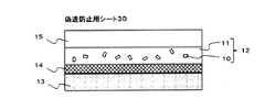
本発明の偽造防止用シートについて図面を参照しながら説明する。図3は本発明の一実施形態に係る偽造防止用シートの一例を示す概略断面図である。図3に示す偽造防止用シート30は、透明樹脂11中に所定の微粒子10が分散された微粒子含有層12からなるものである。 The anti-counterfeit sheet of the present invention will be described with reference to the drawings. FIG. 3 is a schematic cross-sectional view showing an example of the anti-counterfeit sheet according to one embodiment of the present invention. The anti-counterfeit sheet 30 shown in FIG. 3 includes a fine particle-containing
本発明の一実施形態においては、上述した微粒子を含有する微粒子含有層を有することから、本発明の一実施形態に係る偽造防止用シートを用いることにより、偽造防止効果に優れた偽造防止媒体を得ることが可能である。 In one embodiment of the present invention, the anti-counterfeit medium having an excellent anti-counterfeit effect is obtained by using the anti-counterfeit sheet according to one embodiment of the present invention because it has the fine particle-containing layer containing the fine particles described above. It is possible to obtain.
図4は本発明の一実施形態に係る偽造防止用シートの他の例を示す概略断面図である。図4に示す偽造防止用シート30においては、剥離層13と、粘着層14と、透明樹脂11中に所定の微粒子10が分散された微粒子含有層12とが順に積層されている。 FIG. 4 is a schematic cross-sectional view showing another example of the anti-counterfeit sheet according to one embodiment of the present invention. In the anti-counterfeit sheet 30 shown in FIG. 4, a
図5は本発明の一実施形態に係る偽造防止用シートの他の例を示す概略断面図である。図5に示す偽造防止用シート30は、基材15と、基材15上に形成され、透明樹脂11中に所定の微粒子10が分散された微粒子含有層12とを有し、微粒子含有層12側に粘着層14および剥離層13が順に積層されている。 FIG. 5 is a schematic sectional view showing another example of a forgery-preventing sheet according to an embodiment of the present invention. The anti-counterfeit sheet 30 shown in FIG. 5 includes a
図6は本発明の一実施形態に係る偽造防止用シートの他の例を示す概略断面図である。図6に示す偽造防止用シート30は、基材15と、基材15上に形成され、透明樹脂11中に所定の微粒子10が分散された微粒子含有層12と、微粒子含有層12上に形成されたハードコート層16とを有し、基材15側に粘着層14および剥離層13が順に積層されている。 FIG. 6 is a schematic sectional view showing another example of a forgery-preventing sheet according to an embodiment of the present invention. The anti-counterfeit sheet 30 shown in FIG. 6 is formed on the
図7は本発明の一実施形態に係る偽造防止用シートの他の例を示す概略断面図である。図7に示す偽造防止用シート30においては、剥離層13と、粘着層14と、ホログラム層17と、透明樹脂11中に所定の微粒子10が分散された微粒子含有層12とが順に積層されている。 FIG. 7 is a schematic cross-sectional view showing another example of the anti-counterfeit sheet according to one embodiment of the present invention. In the anti-counterfeit sheet 30 shown in FIG. 7, a
図8は本発明の一実施形態に係る偽造防止用シートの他の例を示す概略断面図である。図8に示す偽造防止用シート30は、基材15と、基材15上に形成され、透明樹脂11中に所定の微粒子10が分散された微粒子含有層12と、微粒子含有層12上に形成されたハードコート層16とを有し、基材15側にホログラム層17と粘着層14と剥離層13とが順に積層されている。 FIG. 8 is a schematic cross-sectional view showing another example of a forgery-preventing sheet according to an embodiment of the present invention. The anti-counterfeit sheet 30 shown in FIG. 8 is formed on the
このように、本発明の一実施形態に係る偽造防止用シートは、微粒子含有層以外に他の構成を有していてもよい。以下、本発明の一実施形態に係る偽造防止用シートにおける各構成について説明する。 Thus, the anti-counterfeit sheet according to an embodiment of the present invention may have other configurations in addition to the fine particle-containing layer. Hereinafter, each structure in the forgery prevention sheet | seat which concerns on one Embodiment of this invention is demonstrated.
<5.1.微粒子含有層>
本発明の一実施形態に係る微粒子含有層は、上述の微粒子が透明樹脂中に分散されたものである。なお、微粒子については、上記<1.微粒子>の項に記載した内容と同様とすることができるので、ここでの説明は省略する。<5.1. Fine particle-containing layer>
The fine particle-containing layer according to an embodiment of the present invention is obtained by dispersing the fine particles described above in a transparent resin. For fine particles, the above <1. Since it can be the same as that described in the section of “fine particles”, the description thereof is omitted here.
微粒子としては、1種類の微粒子を用いてもよく、2種以上の微粒子を用いてもよい。例えば、同一の外形形状を有する1種類の微粒子を用いてもよく、異なる外形形状を有する2種類以上の微粒子を用いてもよい。2種類以上の微粒子を用いる場合には、同一形式のコード情報を表現し、別の情報を記録したものであってもよいし、異なる形式のコード情報を表現したものであってもよい。 As the fine particles, one kind of fine particles may be used, or two or more kinds of fine particles may be used. For example, one kind of fine particles having the same outer shape may be used, or two or more kinds of fine particles having different outer shapes may be used. When two or more kinds of fine particles are used, the same type of code information may be expressed and different information may be recorded, or different types of code information may be expressed.
本発明の一実施形態に用いられる透明樹脂の光透過性としては、微粒子含有層中の微粒子が観察可能であれば特に限定されないが、透明樹脂からなる層を微粒子含有層と同じ厚みで形成したときに、可視領域における全光線透過率が10%以上であることが好ましい。なお、上記全光線透過率は、JIS K 7105に準拠して測定した値である。 The light transmittance of the transparent resin used in an embodiment of the present invention is not particularly limited as long as the fine particles in the fine particle-containing layer are observable, but the transparent resin layer is formed with the same thickness as the fine particle-containing layer. Sometimes, the total light transmittance in the visible region is preferably 10% or more. In addition, the said total light transmittance is the value measured based on JISK7105.
透明樹脂としては、上記光透過性を満たすものであれば特に限定されるものではなく、例えば、光硬化性樹脂、熱硬化性樹脂、熱可塑性樹脂のいずれも用いることができる。中でも、光硬化性樹脂、熱硬化性樹脂等の硬化性樹脂が好ましく、特に光硬化性樹脂が好ましい。例えば図5、図6および図8に示すように、基材15上に微粒子含有層12が形成されている場合には、光硬化性樹脂を用いることにより、耐熱性の低い基材も使用することが可能となり、用途の選択肢が広がるからである。また、偽造防止用シートの生産効率を向上させることができるからである。透明樹脂は、上記<3.偽造防止用インク>の項に記載した透明樹脂成分を固化させたものとすることができる。 The transparent resin is not particularly limited as long as it satisfies the above-described light transmittance. For example, any of a photocurable resin, a thermosetting resin, and a thermoplastic resin can be used. Among these, curable resins such as a photocurable resin and a thermosetting resin are preferable, and a photocurable resin is particularly preferable. For example, as shown in FIGS. 5, 6, and 8, when the fine particle-containing
微粒子含有層中の微粒子の含有量としては、本発明の一実施形態に係る偽造防止用シートを偽造防止媒体に用いた場合に、微粒子による真贋判定が可能であれば特に限定されるものではないが、微粒子含有層1cm2当たりに少なくとも1個以上の微粒子が含有されていることが好ましい。 The content of the fine particles in the fine particle-containing layer is not particularly limited as long as the authenticity determination by the fine particles is possible when the anti-counterfeit sheet according to one embodiment of the present invention is used for the anti-counterfeit medium. However, it is preferable that at least one fine particle is contained per 1
また、微粒子含有層が基材上に形成されている場合には、微粒子含有層は基材上に一面に形成されていてもよくパターン状に形成されていてもよい。微粒子含有層のパターン形状が所定の意味を表す形状である場合には、微粒子を隠し情報として利用することができ、偽造防止効果を高めることができる。 Moreover, when the fine particle-containing layer is formed on the substrate, the fine particle-containing layer may be formed on the entire surface of the substrate or may be formed in a pattern. When the pattern shape of the fine particle-containing layer is a shape that represents a predetermined meaning, the fine particles can be used as hidden information, and the effect of preventing forgery can be enhanced.
微粒子含有層の膜厚としては、本発明の一実施形態に係る偽造防止用シートを偽造防止媒体に用いた場合に、微粒子による真贋判定が可能であれば特に限定されるものではなく、本発明の一実施形態に係る偽造防止用シートの層構成や微粒子含有層に含まれる透明樹脂の種類等に応じて適宜選択される。例えば図5、図6および図8に示すように、基材15上に微粒子含有層12が形成されている場合には、微粒子含有層12の膜厚は比較的薄くともよい。一方、図3に例示するように、微粒子含有層12が単独で形成されている場合には、自己支持性の観点から、微粒子含有層の膜厚は比較的厚いことが好ましい。また、微粒子含有層に含まれる透明樹脂が硬化性樹脂である場合には、割れを抑制する観点から、微粒子含有層の膜厚は比較的薄いことが好ましい。具体的に、微粒子含有層の膜厚は、0.1μm〜500μm程度とすることができ、1μm〜100μmの範囲内であることが好ましい。 The film thickness of the fine particle-containing layer is not particularly limited as long as the authenticity determination by fine particles is possible when the anti-counterfeit sheet according to one embodiment of the present invention is used as an anti-counterfeit medium. The layer structure of the anti-counterfeit sheet according to one embodiment, the type of the transparent resin contained in the fine particle-containing layer, and the like are appropriately selected. For example, as shown in FIGS. 5, 6, and 8, when the fine particle-containing
微粒子含有層の形成方法としては、例えば、上述した偽造防止用インクを塗布し、固化させる方法が挙げられる。例えば図5、図6および図8に示すように、基材15上に微粒子含有層12が形成されている場合には、基材15上に偽造防止用インクを塗布し、固化させることで、微粒子含有層12を形成することができる。また、図3に例示するように、微粒子含有層12が単独で形成されている場合には、基板上に偽造防止用インクを塗布し、固化させた後、基板から微粒子含有層12を剥離することで、微粒子含有層12を単独で得ることができる。この際に用いられる基板としては、光透過性を有していても有さなくてもよく、例えば、ガラス基板、樹脂基板等を用いることができる。 Examples of the method for forming the fine particle-containing layer include a method in which the above-described anti-counterfeit ink is applied and solidified. For example, as shown in FIGS. 5, 6, and 8, when the fine particle-containing
偽造防止用インクの塗布方法としては、任意の方法を用いることができる。また、偽造防止用インクの固化方法としては、透明樹脂の種類に応じて適宜選択される。硬化性樹脂の場合には、光や熱による硬化方法が用いられる。熱可塑性樹脂の場合には、冷却する方法が用いられる。 Any method can be used as a method of applying the anti-counterfeit ink. Further, the solidification method of the anti-counterfeit ink is appropriately selected according to the type of the transparent resin. In the case of a curable resin, a curing method using light or heat is used. In the case of a thermoplastic resin, a cooling method is used.
<5.2.基材>
本発明の一実施形態においては、図5、図6および図8に例示するように、微粒子含有層12が基材15上に形成されていてもよい。本発明の一実施形態に係る偽造防止用シートの強度を高めることができ、また容易に取り扱うことができるからである。中でも、微粒子含有層に含まれる透明樹脂が硬化性樹脂である場合には、微粒子含有層の割れを抑制する観点から、微粒子含有層は比較的薄いことが好ましいので、基材上に微粒子含有層が形成されていることが好ましい。また、本発明の一実施形態に係る偽造防止用シートを偽造防止媒体に適用した際に、図5に例示するように、基材15が微粒子含有層12よりも表面側となるように配置されている場合には、基材により微粒子含有層を保護することもできる。図6に例示する層構成の場合には、不透明基材を使用することもできる。<5.2. Base material>
In one embodiment of the present invention, the fine particle-containing
本発明の一実施形態に用いられる基材は、光透過性を有していてもよく有さなくてもよく、基材の形成位置により適宜選択される。本発明の一実施形態に係る偽造防止用シートを偽造防止媒体に適用した際に、図5に例示するように、基材15が微粒子含有層12よりも表面側となるように配置されている場合や、図8に例示するように、基材15がホログラム層17よりも表面側となるように配置されている場合には、基材は光透過性を有することが好ましい。一方、本発明の一実施形態に係る偽造防止用シートを偽造防止媒体に適用した際に、図6に例示するように、基材15が微粒子含有層12よりも裏面側となるように配置されている場合には、基材は光透過性を有していてもよく有さなくてもよい。 The base material used in one embodiment of the present invention may or may not have optical transparency, and is appropriately selected depending on the formation position of the base material. When the anti-counterfeit sheet according to an embodiment of the present invention is applied to an anti-counterfeit medium, the
基材が光透過性を有する場合、その光透過性としては、微粒子含有層中の微粒子が観察可能であれば特に限定されないが、可視領域における全光線透過率が10%以上であることが好ましい。 When the substrate has light transmittance, the light transmittance is not particularly limited as long as the fine particles in the fine particle-containing layer can be observed, but the total light transmittance in the visible region is preferably 10% or more. .
また、基材は、フレキシブル性を有することが好ましい。本発明の一実施形態に係る偽造防止用シートを種々の形状の偽造防止媒体に適用することが可能となるからである。 Moreover, it is preferable that a base material has flexibility. This is because the anti-counterfeit sheet according to an embodiment of the present invention can be applied to anti-counterfeit media having various shapes.
このような基材としては、一般的な樹脂基材を用いることができる。例えば、ポリエチレンテレフタレート、ポリ塩化ビニル、ポリカーボネート、ポリプロピレン、ポリエチレン、ポリスチレン、ポリアリレート、トリアセチルセルロース、ジアセチルセルロース、ポリメタクリル酸メチル、ポリイミド、ポリアミド等の樹脂基材を挙げることができる。 As such a base material, a general resin base material can be used. Examples thereof include resin base materials such as polyethylene terephthalate, polyvinyl chloride, polycarbonate, polypropylene, polyethylene, polystyrene, polyarylate, triacetyl cellulose, diacetyl cellulose, polymethyl methacrylate, polyimide, and polyamide.
また、基材の表面は、微粒子含有層との密着性を向上させるために、易接着処理が施されていることが好ましい。易接着処理としては、微粒子含有層および基材を接着させることができれば特に限定されるものではなく、例えば、プラズマ処理、コロナ放電処理、グロー放電処理、火炎処理等の物理的処理、あるいは、クロム酸、シランカップリング剤、プライマー剤等を使用した化学的処理を挙げることができる。中でも、プライマー剤を用いた化学的処理であることが好ましい。プライマー剤は、基材製造時に処理されるものと、製造後の基材表面に処理されるものと、いずれの場合も好適である。プライマー剤で処理した基材としては、市販されているものを用いることができる。また、製造後の基材表面を処理するプライマー剤としては、上記偽造防止用インクと密着するものであればよい。 The surface of the substrate is preferably subjected to an easy adhesion treatment in order to improve the adhesion with the fine particle-containing layer. The easy adhesion treatment is not particularly limited as long as the fine particle-containing layer and the substrate can be adhered to each other. For example, physical treatment such as plasma treatment, corona discharge treatment, glow discharge treatment, flame treatment, or chromium treatment A chemical treatment using an acid, a silane coupling agent, a primer agent, or the like can be given. Among these, chemical treatment using a primer agent is preferable. In any case, the primer agent is suitable for treatment at the time of production of the substrate and for treatment of the surface of the substrate after production. A commercially available substrate can be used as the substrate treated with the primer agent. In addition, the primer agent for treating the surface of the substrate after production may be any one that can be in close contact with the anti-counterfeit ink.
基材の厚みは、本発明の一実施形態に係る偽造防止用シートの用途や種類等に応じて適宜選択されるものであるが、1μm〜800μm程度とすることができ、好ましくは10μm〜50μmの範囲内である。 The thickness of the base material is appropriately selected according to the use or type of the anti-counterfeit sheet according to one embodiment of the present invention, and can be about 1 μm to 800 μm, preferably 10 μm to 50 μm. Is within the range.
<5.3.粘着層>
本発明の一実施形態においては、図4〜図8に例示するように、微粒子含有層12上に粘着層14が積層されていてもよい。粘着層を介して、本発明の一実施形態に係る偽造防止用シートを貼付することができるからである。<5.3. Adhesive layer>
In one embodiment of the present invention, as illustrated in FIGS. 4 to 8, an
粘着層は、基材上に微粒子含有層が形成されている場合、基材側に積層されていてもよく、微粒子含有層側に積層されていてもよい。微粒子含有層上に後述のハードコート層が形成されている場合には、ハードコート層とは反対側の面に粘着層が配置される。また、微粒子含有層とホログラム層とが積層されている場合には、ホログラム層側に粘着層が配置される。 When the fine particle-containing layer is formed on the substrate, the adhesive layer may be laminated on the substrate side, or may be laminated on the fine particle-containing layer side. When a hard coat layer described later is formed on the fine particle-containing layer, the adhesive layer is disposed on the surface opposite to the hard coat layer. When the fine particle-containing layer and the hologram layer are laminated, an adhesive layer is disposed on the hologram layer side.
粘着層の材料としては、粘着層を介して本発明の一実施形態に係る偽造防止用シートを貼付することができれば特に限定されるものではなく、例えば、熱可塑系、熱硬化系、光硬化系、エラストマー系のいずれも用いることができ、偽造防止用シートの用途や種類等に応じて適宜選択される。偽造防止用シートを転写箔として使用する場合には、ヒートシール性を有する粘着層が用いられる。 The material of the adhesive layer is not particularly limited as long as the anti-counterfeit sheet according to one embodiment of the present invention can be pasted through the adhesive layer, for example, thermoplastic, thermosetting, photocuring Any of the system and elastomer can be used, and it is appropriately selected according to the use and type of the anti-counterfeit sheet. When the anti-counterfeit sheet is used as a transfer foil, an adhesive layer having heat sealability is used.
粘着層の膜厚は、粘着層を介して本発明の一実施形態に係る偽造防止用シートを貼付することができれば特に限定されるものではなく、例えば1μm〜100μm程度とすることができる。粘着層の形成方法は、公知の方法を用いることができる。 The film thickness of the pressure-sensitive adhesive layer is not particularly limited as long as the anti-counterfeit sheet according to an embodiment of the present invention can be attached via the pressure-sensitive adhesive layer, and can be, for example, about 1 μm to 100 μm. A known method can be used as a method for forming the adhesive layer.
<5.4.剥離層>
本発明の一実施形態においては、図4〜図8に例示するように、微粒子含有層12上に粘着層14と剥離層13とが順に積層されていてもよい。粘着層および剥離層が積層されていることにより、本発明の一実施形態に係る偽造防止用シートの取り扱いが容易になるからである。本発明の一実施形態に係る偽造防止用シートは、偽造防止媒体に適用される際には、剥離層を剥がして用いられる。<5.4. Release layer>
In one embodiment of the present invention, as illustrated in FIGS. 4 to 8, the
剥離層としては、剥離性を有するものであれば特に限定されるものではなく、例えば、一般的な樹脂基材を用いることができる。 The release layer is not particularly limited as long as it has releasability. For example, a general resin substrate can be used.
<5.5.ハードコート層>
本発明の一実施形態においては、図6および図8に例示するように、微粒子含有層12上にハードコート層16が形成されていてもよい。ハードコート層により微粒子含有層を保護することができるからである。ハードコート層は、本発明の一実施形態に係る偽造防止用シートを偽造防止媒体に適用した際に、図6および図8に例示するように、ハードコート層16が微粒子含有層12よりも表面側となるように配置される。<5.5. Hard coat layer>
In one embodiment of the present invention, a
ハードコート層は光透過性を有する。ハードコート層の光透過性としては、微粒子含有層中の微粒子が観察可能であれば特に限定されないが、可視領域における全光線透過率が10%以上であることが好ましく、中でも50%以上であることが好ましく、特に80%以上であることが好ましい。 The hard coat layer is light transmissive. The light transmittance of the hard coat layer is not particularly limited as long as the fine particles in the fine particle-containing layer can be observed, but the total light transmittance in the visible region is preferably 10% or more, and more preferably 50% or more. It is preferable that it is 80% or more especially.
ハードコート層の材料としては、上記光透過性を満たし、微粒子含有層を保護することができるものであれば特に限定されるものではなく、例えば、光硬化性樹脂を用いることができる。 The material of the hard coat layer is not particularly limited as long as it satisfies the above light transmittance and can protect the fine particle-containing layer. For example, a photocurable resin can be used.
ハードコート層の膜厚は、微粒子含有層を保護することができれば特に限定されるものではなく、例えば1μm〜100μm程度とすることができる。ハードコート層の形成方法は、公知の方法を用いることができる。 The film thickness of the hard coat layer is not particularly limited as long as the fine particle-containing layer can be protected, and can be, for example, about 1 μm to 100 μm. As a method for forming the hard coat layer, a known method can be used.
<5.6.ホログラム層>
本発明の一実施形態においては、図7および図8に例示するように、微粒子含有層12上にホログラム層17が積層されていてもよい。ホログラム層により偽造防止効果を高めることができるからである。<5.6. Hologram layer>
In one embodiment of the present invention, as illustrated in FIGS. 7 and 8, a
ホログラム層の種類としては特に限定されるものではなく、レリーフ型ホログラム層であってもよく、体積型ホログラム層であってもよい。レリーフ型ホログラム層は生産性に優れており、一方で体積型ホログラム層は偽造防止効果に優れている。ホログラム層としては公知のものを使用することができる。 The type of the hologram layer is not particularly limited, and may be a relief hologram layer or a volume hologram layer. The relief hologram layer is excellent in productivity, while the volume hologram layer is excellent in the forgery prevention effect. A known hologram layer can be used.
ホログラム層は、本発明の一実施形態に係る偽造防止用シートを偽造防止媒体に適用した際に、図7および図8に例示するように、ホログラム層17が微粒子含有層12よりも裏面側になるように配置される。これにより、微粒子含有層をホログラム層の保護層として利用することができる。 As illustrated in FIGS. 7 and 8, when the anti-counterfeit sheet according to an embodiment of the present invention is applied to the anti-counterfeit medium, the
<5.7.偽造防止用シートの形態>
本発明の一実施形態に係る偽造防止用シートは、枚葉であってもよく長尺であってもよい。<5.7. Form of anti-counterfeit sheet>
The anti-counterfeit sheet according to an embodiment of the present invention may be a single sheet or a long sheet.
また、本発明の一実施形態に係る偽造防止用シートの形状としては、特に限定されるものではなく、矩形、多角形、円形、楕円形、その他、任意の形状とすることができる。本発明の一実施形態に係る偽造防止用シートの形状が所定の意味を表す形状である場合には、微粒子を隠し情報として利用することができる。 In addition, the shape of the anti-counterfeit sheet according to the embodiment of the present invention is not particularly limited, and may be a rectangle, a polygon, a circle, an ellipse, or any other shape. When the shape of the anti-counterfeit sheet according to an embodiment of the present invention is a shape that represents a predetermined meaning, the fine particles can be used as hidden information.
本発明の一実施形態における微粒子含有層では、図3に示すように、微粒子10を透明樹脂11中に分散させている。このようにして偽造防止を図る場合、微粒子が透明樹脂中に分散されていることにより、一見するだけでは微粒子を発見することができないといった偽造防止効果を付与することができるが、一方、透明樹脂中に分散された微粒子を、形状に基づいて識別することが困難となる場合がある。このような場合には、透明樹脂の屈折率と異なる屈折率の樹脂製の材料を微粒子に用いることで、秘匿性を保ちつつ、微粒子を形状に基づいて識別することが可能となる。 In the fine particle-containing layer in one embodiment of the present invention,
<6.偽造防止媒体>
本発明の一実施形態に係る偽造防止媒体は、上記微粒子、または上記偽造防止用シートを有するものである。<6. Anti-counterfeit media>
An anti-counterfeit medium according to an embodiment of the present invention includes the fine particles or the anti-counterfeit sheet.
図9(a)、(b)は本発明の一実施形態に係る偽造防止媒体の一例を示す模式図であり、図9(a)は上面図、図9(b)は図9(a)のC−C線断面図である。図9(a)、(b)に示す偽造防止媒体40においては、支持体41上に、上述した微粒子10が透明樹脂11中に分散された微粒子含有層12が形成されている。 9A and 9B are schematic views showing an example of an anti-counterfeit medium according to an embodiment of the present invention. FIG. 9A is a top view, and FIG. 9B is FIG. 9A. It is a CC sectional view taken on the line. In the anti-counterfeit medium 40 shown in FIGS. 9A and 9B, a fine particle-containing
図10(a)〜(c)は本発明の一実施形態に係る偽造防止媒体の他の例を示す模式図であり、図10(a)は上面図、図10(b)は図10(a)のD−D線断面図である。図10(a)(b)に示す偽造防止媒体40おいては、支持体41上に第1樹脂層42と上述した微粒子10が透明樹脂11中に分散された微粒子含有層12からなる偽造防止用シート30と第2樹脂層43とが積層されており、偽造防止媒体40の内部に偽造防止用シート30が埋め込まれている。偽造防止媒体の内部に偽造防止用シートが埋め込まれている場合には、偽造防止用シートが剥がされて悪用されるのを防ぐことができる。 FIGS. 10A to 10C are schematic views showing other examples of the forgery prevention medium according to the embodiment of the present invention. FIG. 10A is a top view, and FIG. It is the DD sectional view taken on the line of a). In the anti-counterfeit medium 40 shown in FIGS. 10 (a) and 10 (b), anti-counterfeiting comprising a
本発明の一実施形態に係る偽造防止媒体においては、光学的に読取可能なコード情報に基づく形状を表現した上記微粒子を有することにより、拡大したとしても、物品に含まれる微粒子または識別部を直接認識することが困難となり、高い偽造防止機能を付与することが可能であり、また、容易に真贋判定することが可能な偽造防止媒体を作製することが可能となる。 In the anti-counterfeit medium according to an embodiment of the present invention, the fine particles or the identification part included in the article can be directly detected even if the fine particles are enlarged by having the fine particles expressing the shape based on the optically readable code information. It becomes difficult to recognize, and a high anti-counterfeiting function can be provided, and an anti-counterfeit medium that can easily determine authenticity can be produced.
以下、本発明の一実施形態に係る偽造防止媒体における各構成について説明する。なお、微粒子については、上記<1.微粒子>の項に記載したものと同様とすることができるので、ここでの記載は省略する。 Hereinafter, each structure in the forgery prevention medium which concerns on one Embodiment of this invention is demonstrated. For fine particles, the above <1. Since it can be the same as that described in the section “Fine particles”, description thereof is omitted here.
微粒子を用いる場合において、支持体上に微粒子を固定・固着させる方法としては、支持体上に上述した偽造防止用インクを塗布し、固化させる方法や、支持体上に上述した偽造防止用トナーを転写する方法、支持体上に上述した偽造防止用シートを貼付もしくは埋め込む方法を用いることができる。 In the case of using fine particles, as a method of fixing and fixing the fine particles on the support, a method of applying the above-described anti-counterfeit ink on the support and solidifying, or the above-described anti-counterfeit toner on the support is used. A method of transferring and a method of sticking or embedding the above-described anti-counterfeit sheet on the support can be used.
支持体上に偽造防止用シートを貼付する方法としては、そのまま貼っても良く、転写しても良い。さらに、偽造防止媒体が複数層から構成される場合には、偽造防止用シートを偽造防止媒体の構成層間に埋め込んでも良い。ここで、偽造防止用シートを埋め込む方法としては、例えば、偽造防止媒体の支持体上に所望の構成層を積層し、各層間を接着層、粘着層、熱圧着等によって接着する方法が挙げられる。なお、偽造防止媒体内に積層される偽造防止用シートは、一部に設けられていても良く、全体に設けられていても良い。また、偽造防止媒体中のその他の構成層としては、偽造防止媒体の種類に応じて、適宜選択されるものである。 As a method of sticking the anti-counterfeit sheet on the support, it may be stuck as it is or transferred. Furthermore, when the anti-counterfeit medium is composed of a plurality of layers, the anti-counterfeit sheet may be embedded between the constituent layers of the anti-counterfeit medium. Here, as a method of embedding the anti-counterfeit sheet, for example, a method of laminating a desired constituent layer on a support of an anti-counterfeit medium and adhering each layer by an adhesive layer, an adhesive layer, thermocompression bonding or the like can be mentioned. . Note that the anti-counterfeit sheet laminated in the anti-counterfeit medium may be provided in part or in the entirety. Further, other constituent layers in the forgery prevention medium are appropriately selected according to the type of the forgery prevention medium.
本発明の一実施形態に用いられる支持体としては、本発明の一実施形態に係る偽造防止媒体の用途に応じて適宜選択されるものである。支持体は、光透過性を有していてもよく有さなくてもよい。支持体の材料としては、例えば、ガラス、樹脂、金属、紙等が挙げられる。 The support used in one embodiment of the present invention is appropriately selected according to the application of the forgery prevention medium according to one embodiment of the present invention. The support may or may not have optical transparency. Examples of the material for the support include glass, resin, metal, paper, and the like.
また、支持体と第1樹脂層と偽造防止用シートと第2樹脂層とが積層されている場合、第1樹脂層は光透過性を有していてもよく有さなくてもよい。中でも、支持体と第1樹脂層との間に、任意の情報を記録し得るまたは有する機能層(例えば受像層、ホログラム層等)が形成されている場合には、第1樹脂層は光透過性を有することが好ましい。第1樹脂層が光透過性を有する場合、その光透過性としては、偽造防止用シートを構成する基材の光透過性と同様とすることができる。第1樹脂層としては、例えば一般的な樹脂基材を用いることができる。一方、第2樹脂層は、光透過性を有するものである。第2樹脂層の光透過性としては、偽造防止用シートを構成する基材の光透過性と同様とすることができる。第2樹脂層としては、例えば一般的な樹脂基材を用いることができる。 Moreover, when the support body, the 1st resin layer, the forgery prevention sheet, and the 2nd resin layer are laminated | stacked, the 1st resin layer does not need to have a light transmittance. In particular, when a functional layer (for example, an image receiving layer or a hologram layer) capable of recording or having arbitrary information is formed between the support and the first resin layer, the first resin layer transmits light. It is preferable to have properties. When the first resin layer has light transmittance, the light transmittance can be the same as the light transmittance of the base material constituting the anti-counterfeit sheet. As the first resin layer, for example, a general resin substrate can be used. On the other hand, the second resin layer is light transmissive. The light transmittance of the second resin layer can be the same as the light transmittance of the base material constituting the anti-counterfeit sheet. As the second resin layer, for example, a general resin substrate can be used.
本発明の一実施形態に係る偽造防止媒体の用途としては、例えば、金券、ギフトカード、クレジットカード、IDカード、パスポート、運転免許証、ブランド品、自動車部品、精密機器部品、家電、化粧品、医薬品、食品、OAサプライ品、スポーツ用品、CD、DVD、ソフトウェア、たばこ、お酒等を挙げることができる。
上述した本発明の一実施形態に係る微粒子、または微粒子を含む偽造防止用シートを、パスポートや運転免許証等の身分証明用の顔写真や識別情報の上に配置することで、顔写真や識別情報だけでなく、微粒子によっても真偽を検証できることになり、偽造防止効果の向上が図れる。Applications of the anti-counterfeit medium according to an embodiment of the present invention include, for example, gold vouchers, gift cards, credit cards, ID cards, passports, driver's licenses, brand products, automobile parts, precision equipment parts, home appliances, cosmetics, and pharmaceuticals. , Food, OA supplies, sports equipment, CDs, DVDs, software, cigarettes, liquor, etc.
By disposing the fine particles according to one embodiment of the present invention described above or the anti-counterfeit sheet containing the fine particles on a face photo or identification information for identification such as a passport or a driver's license, The authenticity can be verified not only by the information but also by the fine particles, and the forgery prevention effect can be improved.
<7.記録情報読取装置>
<7.1.装置構成>
記録情報読取装置20は、スマートフォン、タブレット端末等の情報処理機能、ネットワーク通信機能、表示機能を備えた携帯可能な端末装置であり、偽造防止用シート等を撮影することにより、偽造防止シートに付加された微粒子を含む画像を取得し、取得された画像を解析することにより微粒子に記録された情報を取得する。<7. Recorded information reader>
<7.1. Device configuration>
The recorded information reading device 20 is a portable terminal device having an information processing function, a network communication function, and a display function such as a smartphone and a tablet terminal, and is added to the anti-counterfeit sheet by photographing the anti-counterfeit sheet. An image containing the fine particles is acquired, and the information recorded on the fine particles is acquired by analyzing the acquired image.
記録情報読取装置20は、上述のように、スマートフォン、タブレット端末等により実現可能であるが、本実施形態では、多機能型携帯電話機であるスマートフォンに、「アプリ」と呼ばれる専用のプログラムを組み込むことにより実現する。スマートフォンは、多機能型携帯電話機であるが、タッチパネルで画面を操作して制御可能なコンピュータとしての機能も有している。 As described above, the recorded information reading device 20 can be realized by a smartphone, a tablet terminal, or the like. However, in this embodiment, a dedicated program called “application” is incorporated in a smartphone that is a multi-function mobile phone. To achieve. A smartphone is a multi-function mobile phone, but also has a function as a computer that can be controlled by operating a screen with a touch panel.
図11は、記録情報読取装置20のハードウェア構成図である。図11に示すように、記録情報読取装置20は、CPU(Central Processing Unit)20aと、メインメモリであるRAM(Random Access Memory)20bと、CPU20aが実行するプログラムやデータを記憶するためのハードディスク、フラッシュメモリ等の大容量の記憶装置20cと、キーボードやタッチパネル等の指示入力部20dと、データ記憶媒体等の外部装置とデータ通信するためのデータ入出力I/F(インタフェース)20eと、液晶ディスプレイや有機ELディスプレイ等の表示デバイスである表示部20fと、RF回路(高周波回路)を備え、無線により、携帯電話網およびネットワークを介して他のコンピュータと通信を行うための通信部20gと、CCDやCMOS等の撮像素子を有するカメラ20hを備えており、互いにバスを介して接続されている。現実には、スマートフォンは、図11に示した以外にも、マイクロフォン、スピーカ等を有しているが、本実施形態とは無関係であるため省略している。 FIG. 11 is a hardware configuration diagram of the recorded information reading device 20. As shown in FIG. 11, the recorded information reading device 20 includes a CPU (Central Processing Unit) 20a, a main memory RAM (Random Access Memory) 20b, a hard disk for storing programs and data executed by the
図12は、記録情報読取装置20の機能ブロック図である。図12において、21はコード情報記憶手段、22は撮像手段、23は画像拡大手段、24は特徴部分取得手段、25は画像解析手段、26は表示手段である。コード情報記憶手段21は、微粒子10を撮像して取得した情報と比較するためのコード情報を記憶したものであり、記憶装置20cにより実現される。撮像手段22は、CPU20aの命令によりカメラ20hが撮像を行うことにより実現される。画像拡大手段23は、撮像手段22の撮像により取得された画像を拡大して拡大画像を取得する。特徴部分取得手段24は、拡大画像の中から微粒子を撮像した微粒子部分を抽出し、さらに、抽出した微粒子部分から、接続部部分を除去して、コード要素1を含む特徴部分を取得する。画像解析手段25は、取得したコード要素1(コードシンボル画像)の幅や間隔を解析して、記録情報を取得する。画像解析手段25による記録情報の取得は、公知のバーコードリーダーに組み込まれているアルゴリズムに従って行うことができる。表示手段26は、画像解析手段25により取得された記録情報を表示出力するものであり、表示部20fにより実現される。より具体的には、特徴部分取得手段24は、第1方向に配置される各コード要素1の数と、各コード要素1の第1方向の幅と、第1方向に隣接する2つのコード要素1間の隙間と、の少なくとも一つにより、特徴部分に含まれるコード情報を識別する。 FIG. 12 is a functional block diagram of the recorded information reading device 20. In FIG. 12, 21 is a code information storage means, 22 is an imaging means, 23 is an image enlargement means, 24 is a characteristic part acquisition means, 25 is an image analysis means, and 26 is a display means. The code
図12に示した各構成手段は、現実には図11に示したように、スマートフォンに、専用のプログラムを搭載することにより実現される。すなわち、コンピュータでもあるスマートフォンが、専用のプログラムに従って各手段の内容を実行することになる。なお、本明細書において、コンピュータとは、CPU等の演算処理部を有し、データ処理が可能な装置を意味し、パーソナルコンピュータなどの汎用コンピュータだけでなく、スマートフォン、タブレット端末等も含む。 Each component shown in FIG. 12 is actually realized by mounting a dedicated program on a smartphone as shown in FIG. That is, the smartphone, which is also a computer, executes the contents of each means according to a dedicated program. Note that in this specification, a computer means an apparatus having an arithmetic processing unit such as a CPU and capable of data processing, and includes not only a general-purpose computer such as a personal computer but also a smartphone, a tablet terminal, and the like.
図11に示した記憶装置3には、CPU20aを動作させ、コンピュータであるスマートフォンを、記録情報読取装置20として機能させるための専用のプログラムが実装されている。この専用のプログラムを実行することにより、CPU20aは、撮像手段22、画像拡大手段23、特徴部分取得手段24、画像解析手段25、表示手段26としての機能を実現することになる。また、記憶装置20cは、コード情報記憶手段21として機能するだけでなく、記録情報読取装置20としての処理に必要な様々なデータを記憶する。 In the storage device 3 illustrated in FIG. 11, a dedicated program for operating the
<7.2.処理動作>
次に、本発明の一実施形態に係る記録情報読取装置の処理動作について、図12のフローチャートを用いて説明する。まず、偽造防止用シート30、偽造防止媒体40等の撮像を行う(ステップS10)。具体的には、利用者が、記録情報読取装置20のカメラ部分を、偽造防止用シート30、偽造防止媒体40等の所定の箇所に向けて、指示入力部10dに対して操作を行うことにより、撮像手段22が偽造防止用シートの所定の箇所を撮像する。偽造防止用シート30、偽造防止媒体40等の真贋判定を行う者は、その偽造防止用シート30、偽造防止媒体40等が本物である場合に、どの辺りに微粒子が存在するかを事前に知らされているので、適切な箇所を撮像することができる。撮像手段22による撮像により、偽造防止用シート30、偽造防止媒体40等の所定の箇所の撮像画像が得られる。<7.2. Processing action>
Next, the processing operation of the recorded information reading apparatus according to the embodiment of the present invention will be described using the flowchart of FIG. First, the anti-counterfeit sheet 30, the anti-counterfeit medium 40, etc. are imaged (step S10). Specifically, the user operates the instruction input unit 10d with the camera portion of the recorded information reading device 20 directed to a predetermined location such as the anti-counterfeit sheet 30 and the anti-counterfeit medium 40. The imaging means 22 images a predetermined portion of the anti-counterfeit sheet. A person who determines the authenticity of the anti-counterfeit sheet 30, anti-counterfeit medium 40, etc. knows in advance where fine particles are present when the anti-counterfeit sheet 30, anti-counterfeit medium 40, etc. are genuine. Therefore, it is possible to image an appropriate location. By imaging by the imaging means 22, captured images of predetermined locations such as the anti-counterfeit sheet 30 and the anti-counterfeit medium 40 are obtained.
次に、画像拡大手段23が、撮像画像を拡大する(ステップS20)。具体的には、縦、横の画素数を所定倍に増加させて、画素間を補間することにより、画素数を増加させた拡大画像を得る。この際、公知の鮮鋭化処理を施して、微粒子の輪郭部分を際立たせるようにしてもよい。 Next, the
次に、特徴部分取得手段24が、拡大画像中から微粒子部分を抽出する(ステップS30)。具体的には、拡大画像中の画素値の変化から微粒子が映っている微粒子部分を抽出する。微粒子部分の抽出は、事前に登録された特徴に該当する箇所を検出することにより行う。例えば、バーコードを表現した微粒子の場合、所定方向(コード要素1を横切る方向)に交互に画素値の大きな変化が生じ、それと直交する方向(コード要素1に平行な方向)に一定の画素値が連続する場合、微粒子部分として特定する。 Next, the characteristic
続いて、特徴部分取得手段24が、抽出した微粒子部分から特徴部分を取得する(ステップS40)。具体的には、微粒子部分のうち、コード要素1の画素とコード要素1の画素値と近い値の画素をコード要素1と直交する接続部2であるとして除去する。この結果、コード要素1の並びだけの特徴部分が取得される。 Subsequently, the characteristic
次に、画像解析手段25が、取得された特徴部分を解析して、記録された情報を取得する(ステップS50)。具体的には、特徴部分のコード要素1の幅と、その間隔を解析して取得し、コード情報記憶手段21に記憶されたコード情報を参照することにより、取得した特徴部分に記録された記録情報を取得する。 Next, the
続いて、表示手段26が、取得された記録情報を画面に表示出力する(ステップS60)。画面を確認することにより、利用者は、微粒子に記録されていた情報を知ることができる。記録情報の出力は、必ずしも画面への表示出力とする必要はなく、プリンタ等への印刷や、データ入出力I/F10eを介して外部へデータとして出力するようにしてもよい。 Subsequently, the display means 26 displays and outputs the acquired recording information on the screen (step S60). By confirming the screen, the user can know the information recorded in the fine particles. The output of the recording information is not necessarily a display output on the screen, but may be output as data to the outside via printing on a printer or the like via the data input / output I / F 10e.
以上、本発明の好適な実施形態について説明したが、本発明は上記実施形態に限定されず、種々の変形が可能である。例えば、上記実施形態では微粒子が表現するコード情報として、一次元のバーコードを用いたが、QRコード(登録商標)等の二次元コードや、その他のコード情報を用いるようにしてもよい。どのようなコード情報であっても、透明樹脂中で微粒子が分離しないように、本来のコード要素以外に接続部を有する構成となっている。 The preferred embodiments of the present invention have been described above. However, the present invention is not limited to the above embodiments, and various modifications can be made. For example, although the one-dimensional barcode is used as the code information expressed by the fine particles in the above-described embodiment, a two-dimensional code such as a QR code (registered trademark) or other code information may be used. Whatever the code information, the connection portion is provided in addition to the original code element so that the fine particles are not separated in the transparent resin.
また、上記実施形態では、専用のプログラムを組み込むことにより、スマートフォンを、画像拡大手段23を備えた記録情報読取装置20として機能させるようにしたが、スマートフォンに画像拡大手段としての機能を備えず、市販のマクロレンズを利用するようにしてもよい。マクロレンズとは、一般より高い撮影倍率で接写撮影ができるように設計されたレンズである。近年では、クリップ形状となるアタッチメントを備えたスマートフォン用のマクロレンズも市販されているため、このマクロレンズを、特徴部分取得手段24、画像解析手段25としての機能を備えたスマートフォンに装着することにより、画像拡大手段23を備えた記録情報読取装置20と同等の機能を実現することができる。 Moreover, in the said embodiment, although the smart phone was made to function as the recording information reading apparatus 20 provided with the image expansion means 23 by incorporating a special program, a smart phone is not equipped with the function as an image expansion means, A commercially available macro lens may be used. A macro lens is a lens designed so that close-up photography can be performed at a higher magnification than usual. In recent years, since macro lenses for smartphones equipped with clip-shaped attachments are also commercially available, by attaching these macro lenses to smartphones having functions as the characteristic part acquisition means 24 and the image analysis means 25 A function equivalent to that of the recorded information reading device 20 including the image enlarging means 23 can be realized.
Claims (12)
Translated fromJapanese前記各コード要素は、前記接続部の延在方向に沿って、離隔して配置されていることを特徴とする請求項2に記載の微粒子。The connecting portion extends in one direction, or extends in a direction that changes continuously or intermittently,
The fine particles according to claim 2, wherein the cord elements are spaced apart from each other along the extending direction of the connecting portion.
前記各コード要素は、前記第1方向に交差する第2方向に延在しており、
前記各コード要素の各一端は前記接続部に接続されていることを特徴とする請求項2に記載の微粒子。The connecting portion extends in a first direction;
Each cord element extends in a second direction intersecting the first direction;
The fine particles according to claim 2, wherein each one end of each cord element is connected to the connecting portion.
前記コード情報は、前記第1方向に配置される前記各コード要素の数と、前記各コード要素の前記第1方向の幅と、前記第1方向に隣接する2つのコード要素間の隙間と、の少なくとも一つを可変調整することにより生成されることを特徴とする請求項4に記載の微粒子。The lengths of the respective code elements in the second direction are the same;
The code information includes a number of the code elements arranged in the first direction, a width of the code elements in the first direction, and a gap between two code elements adjacent in the first direction, The fine particles according to claim 4, wherein the fine particles are produced by variably adjusting at least one of the following.
前記撮像画像の一部を拡大した拡大画像を取得する画像拡大手段と、
前記拡大画像中から前記微粒子に対応する微粒子部分を抽出し、抽出した前記微粒子部分から特徴部分を取得する特徴部分取得手段と、
前記特徴部分に対して解析を行い記録された情報を取得する画像解析手段と、
解析により得られた情報を出力する出力手段と、を有することを特徴とする微粒子の記録情報読取装置。An imaging unit that acquires a captured image obtained by capturing the microparticle, the microparticle having a shape that can be identified by enlarging and that is formed so as to represent a shape based on optically readable code information; ,
Image enlargement means for obtaining an enlarged image obtained by enlarging a part of the captured image;
Extracting a fine particle portion corresponding to the fine particle from the enlarged image, and obtaining a characteristic portion from the extracted fine particle portion; and
Image analysis means for analyzing the characteristic portion and obtaining recorded information;
Output means for outputting information obtained by analysis, and a fine particle recorded information reading device.
前記特徴部分取得手段は、前記微粒子部分から前記接続部の画像を除去して、前記コード情報を含む前記特徴部分を取得することを特徴とする請求項10に記載の記録情報読取装置。The shape based on the optically readable code information includes each code element constituting the optically readable code information, and a connection part for connecting each code element,
The recorded information reading apparatus according to claim 10, wherein the feature portion acquisition unit acquires the feature portion including the code information by removing an image of the connection portion from the fine particle portion.
前記各コード要素は、前記第1方向に交差する第2方向に延在しており、
前記各コード要素の各一端は前記接続部に接続されており、
前記特徴部分取得手段は、前記第1方向に配置される前記各コード要素の数と、前記各コード要素の前記第1方向の幅と、前記第1方向に隣接する2つのコード要素間の隙間と、の少なくとも一つにより、前記特徴部分に含まれる前記コード情報を識別することを特徴とする請求項11に記載の記録情報読取装置。The connecting portion extends in a first direction;
Each cord element extends in a second direction intersecting the first direction;
Each one end of each cord element is connected to the connecting portion,
The feature portion acquisition means includes a number of the code elements arranged in the first direction, a width of the code elements in the first direction, and a gap between two code elements adjacent in the first direction. The recorded information reading apparatus according to claim 11, wherein the code information included in the characteristic portion is identified by at least one of the following.
Applications Claiming Priority (3)
| Application Number | Priority Date | Filing Date | Title |
|---|---|---|---|
| JP2015000210 | 2015-01-05 | ||
| JP2015000210 | 2015-01-05 | ||
| PCT/JP2015/086491WO2016111226A1 (en) | 2015-01-05 | 2015-12-28 | Fine particles, ink for forgery prevention, toner for forgery prevention, sheet for forgery prevention, forgery-preventing medium, and recorded information-reading device |
Publications (1)
| Publication Number | Publication Date |
|---|---|
| JPWO2016111226A1true JPWO2016111226A1 (en) | 2017-12-14 |
Family
ID=56355920
Family Applications (1)
| Application Number | Title | Priority Date | Filing Date |
|---|---|---|---|
| JP2016568350APendingJPWO2016111226A1 (en) | 2015-01-05 | 2015-12-28 | Fine particles, anti-counterfeit ink, anti-counterfeit toner, anti-counterfeit sheet, anti-counterfeit medium, and recorded information reader |
Country Status (2)
| Country | Link |
|---|---|
| JP (1) | JPWO2016111226A1 (en) |
| WO (1) | WO2016111226A1 (en) |
Families Citing this family (3)
| Publication number | Priority date | Publication date | Assignee | Title |
|---|---|---|---|---|
| US20200225596A1 (en)* | 2019-01-15 | 2020-07-16 | Xerox Corporation | Toner composition comprising gadolinium oxysulfide particles |
| CN115724253A (en)* | 2022-10-20 | 2023-03-03 | 北京航空航天大学 | Quantum dot two-dimensional code production device and quantum dot two-dimensional code tape and readout device |
| JP2024143773A (en)* | 2023-03-30 | 2024-10-11 | 日東電工株式会社 | Information media and information processing system |
Citations (4)
| Publication number | Priority date | Publication date | Assignee | Title |
|---|---|---|---|---|
| JPH10504112A (en)* | 1994-04-25 | 1998-04-14 | ユニバーシティー オブ ハートフォードシェア | Coded articles for labeling objects |
| WO2009049562A2 (en)* | 2007-10-19 | 2009-04-23 | Krimistop S.R.O. | Intelligent micro-particle containing data and machine-readable variable information and method of its production |
| JP2011248930A (en)* | 2011-09-14 | 2011-12-08 | Toshiba Tec Corp | Code symbol reading device |
| JP2012236369A (en)* | 2011-05-12 | 2012-12-06 | Dainippon Printing Co Ltd | Fine particle, and ink, toner, sheet and medium containing the same for anti-counterfeiting |
- 2015
- 2015-12-28WOPCT/JP2015/086491patent/WO2016111226A1/ennot_activeCeased
- 2015-12-28JPJP2016568350Apatent/JPWO2016111226A1/enactivePending
Patent Citations (4)
| Publication number | Priority date | Publication date | Assignee | Title |
|---|---|---|---|---|
| JPH10504112A (en)* | 1994-04-25 | 1998-04-14 | ユニバーシティー オブ ハートフォードシェア | Coded articles for labeling objects |
| WO2009049562A2 (en)* | 2007-10-19 | 2009-04-23 | Krimistop S.R.O. | Intelligent micro-particle containing data and machine-readable variable information and method of its production |
| JP2012236369A (en)* | 2011-05-12 | 2012-12-06 | Dainippon Printing Co Ltd | Fine particle, and ink, toner, sheet and medium containing the same for anti-counterfeiting |
| JP2011248930A (en)* | 2011-09-14 | 2011-12-08 | Toshiba Tec Corp | Code symbol reading device |
Also Published As
| Publication number | Publication date |
|---|---|
| WO2016111226A1 (en) | 2016-07-14 |
Similar Documents
| Publication | Publication Date | Title |
|---|---|---|
| JP5589939B2 (en) | Fine particles, particle group, anti-counterfeit ink, anti-counterfeit toner, anti-counterfeit sheet and anti-counterfeit medium | |
| CN103260896B (en) | Taggant particle group and there is its false proof ink, false proof toner, false proof sheet material and anti-counterfeiting medium | |
| JP5870506B2 (en) | Anti-counterfeit sheet and anti-counterfeit medium | |
| JP5707909B2 (en) | Method for producing fine particles | |
| Jiang et al. | Scalable inkjet-based structural color printing by molding transparent gratings on multilayer nanostructured surfaces | |
| JP2012121177A (en) | Sheet having identification information, and manufacturing method of the same | |
| CN105121742B (en) | Polynary light emitting-type safety element and the valuable or safety product comprising the safety element | |
| CN104918715A (en) | Optical effect layers showing a viewing angle dependent optical effect, processes and devices for their production, items carrying an optical effect layer, and uses thereof | |
| JP5834692B2 (en) | Individual identification device, individual identification method, and program | |
| CA2972113C (en) | Microparticles and apparatus for smart ink production | |
| RU2664945C1 (en) | Security element | |
| TW201840443A (en) | Method for producing an optical security feature as well as security element and security document | |
| KR102373887B1 (en) | Method for Manufacturing Means Preventing Forgery and Falsification including Photonic Crystal Materials Complex | |
| JPWO2016111226A1 (en) | Fine particles, anti-counterfeit ink, anti-counterfeit toner, anti-counterfeit sheet, anti-counterfeit medium, and recorded information reader | |
| JP2017072694A (en) | Hologram structure | |
| CN114148114A (en) | Anti-counterfeiting film and application method thereof | |
| JP5598294B2 (en) | Tagant manufacturing method and taggant | |
| KR102187266B1 (en) | Manufacturing method of anti-counterfeit apparatus | |
| EP3805005A1 (en) | Security medium printed on which color code for security information is printed using magnetically color turnable photonic crystal ink, and manufacturing method therefor | |
| KR20200050112A (en) | Anti-counterfeit apparatus and manufacturing method thereof | |
| KR20200050579A (en) | Security article having security serial color code using magnetically photonic color changable ink | |
| EP3079917B1 (en) | Security document with test device for a circuit, and method for testing a circuit in a security document | |
| JP2017067916A (en) | Hologram laminate, information recording medium, and method for manufacturing hologram laminate | |
| KR20160115822A (en) | Method of certifying for anti-counterfeit apparatus using the camera | |
| KR20210037976A (en) | Manufacturing method of anti-counterfeit apparatus |
Legal Events
| Date | Code | Title | Description |
|---|---|---|---|
| A621 | Written request for application examination | Free format text:JAPANESE INTERMEDIATE CODE: A621 Effective date:20180830 | |
| A131 | Notification of reasons for refusal | Free format text:JAPANESE INTERMEDIATE CODE: A131 Effective date:20181130 | |
| A02 | Decision of refusal | Free format text:JAPANESE INTERMEDIATE CODE: A02 Effective date:20190524 |