JPWO2016092705A1 - Laser radar equipment - Google Patents
Laser radar equipmentDownload PDFInfo
- Publication number
- JPWO2016092705A1 JPWO2016092705A1JP2016563383AJP2016563383AJPWO2016092705A1JP WO2016092705 A1JPWO2016092705 A1JP WO2016092705A1JP 2016563383 AJP2016563383 AJP 2016563383AJP 2016563383 AJP2016563383 AJP 2016563383AJP WO2016092705 A1JPWO2016092705 A1JP WO2016092705A1
- Authority
- JP
- Japan
- Prior art keywords
- light
- unit
- wind speed
- line
- speed value
- Prior art date
- Legal status (The legal status is an assumption and is not a legal conclusion. Google has not performed a legal analysis and makes no representation as to the accuracy of the status listed.)
- Pending
Links
Images


Classifications
- G—PHYSICS
- G01—MEASURING; TESTING
- G01P—MEASURING LINEAR OR ANGULAR SPEED, ACCELERATION, DECELERATION, OR SHOCK; INDICATING PRESENCE, ABSENCE, OR DIRECTION, OF MOVEMENT
- G01P5/00—Measuring speed of fluids, e.g. of air stream; Measuring speed of bodies relative to fluids, e.g. of ship, of aircraft
- G01P5/26—Measuring speed of fluids, e.g. of air stream; Measuring speed of bodies relative to fluids, e.g. of ship, of aircraft by measuring the direct influence of the streaming fluid on the properties of a detecting optical wave
- G—PHYSICS
- G01—MEASURING; TESTING
- G01S—RADIO DIRECTION-FINDING; RADIO NAVIGATION; DETERMINING DISTANCE OR VELOCITY BY USE OF RADIO WAVES; LOCATING OR PRESENCE-DETECTING BY USE OF THE REFLECTION OR RERADIATION OF RADIO WAVES; ANALOGOUS ARRANGEMENTS USING OTHER WAVES
- G01S17/00—Systems using the reflection or reradiation of electromagnetic waves other than radio waves, e.g. lidar systems
- G01S17/88—Lidar systems specially adapted for specific applications
- G01S17/95—Lidar systems specially adapted for specific applications for meteorological use
- G—PHYSICS
- G01—MEASURING; TESTING
- G01S—RADIO DIRECTION-FINDING; RADIO NAVIGATION; DETERMINING DISTANCE OR VELOCITY BY USE OF RADIO WAVES; LOCATING OR PRESENCE-DETECTING BY USE OF THE REFLECTION OR RERADIATION OF RADIO WAVES; ANALOGOUS ARRANGEMENTS USING OTHER WAVES
- G01S17/00—Systems using the reflection or reradiation of electromagnetic waves other than radio waves, e.g. lidar systems
- G01S17/02—Systems using the reflection of electromagnetic waves other than radio waves
- G01S17/50—Systems of measurement based on relative movement of target
- G01S17/58—Velocity or trajectory determination systems; Sense-of-movement determination systems
- G—PHYSICS
- G01—MEASURING; TESTING
- G01S—RADIO DIRECTION-FINDING; RADIO NAVIGATION; DETERMINING DISTANCE OR VELOCITY BY USE OF RADIO WAVES; LOCATING OR PRESENCE-DETECTING BY USE OF THE REFLECTION OR RERADIATION OF RADIO WAVES; ANALOGOUS ARRANGEMENTS USING OTHER WAVES
- G01S7/00—Details of systems according to groups G01S13/00, G01S15/00, G01S17/00
- G01S7/48—Details of systems according to groups G01S13/00, G01S15/00, G01S17/00 of systems according to group G01S17/00
- G01S7/483—Details of pulse systems
- G01S7/484—Transmitters
- Y—GENERAL TAGGING OF NEW TECHNOLOGICAL DEVELOPMENTS; GENERAL TAGGING OF CROSS-SECTIONAL TECHNOLOGIES SPANNING OVER SEVERAL SECTIONS OF THE IPC; TECHNICAL SUBJECTS COVERED BY FORMER USPC CROSS-REFERENCE ART COLLECTIONS [XRACs] AND DIGESTS
- Y02—TECHNOLOGIES OR APPLICATIONS FOR MITIGATION OR ADAPTATION AGAINST CLIMATE CHANGE
- Y02A—TECHNOLOGIES FOR ADAPTATION TO CLIMATE CHANGE
- Y02A90/00—Technologies having an indirect contribution to adaptation to climate change
- Y02A90/10—Information and communication technologies [ICT] supporting adaptation to climate change, e.g. for weather forecasting or climate simulation
Landscapes
- Engineering & Computer Science (AREA)
- Physics & Mathematics (AREA)
- General Physics & Mathematics (AREA)
- Electromagnetism (AREA)
- Computer Networks & Wireless Communication (AREA)
- Radar, Positioning & Navigation (AREA)
- Remote Sensing (AREA)
- Multimedia (AREA)
- Aviation & Aerospace Engineering (AREA)
- Optical Radar Systems And Details Thereof (AREA)
Abstract
Translated fromJapaneseDescription
Translated fromJapaneseこの発明は、観測領域における風速値を計測するレーザレーダ装置に関するものである。 The present invention relates to a laser radar device that measures a wind speed value in an observation region.
遠隔点の観測領域に存在する物体の位置を計測するものとして、レーダ装置が知られている。レーダ装置は、電磁波又は音波等の波動を観測領域に放射し、対象となる物体で反射された波動を受信する。そして、受信した信号を解析することにより、レーダ装置から物体までの距離や角度を計測する。
レーダ装置において、大気中に浮遊する微小な液体又は固体の粒子(エアロゾル)を対象とし、反射された波動の位相回転量からエアロゾルの動く速度(すなわち風の速度)を知ることができる気象レーダ装置が知られている。気象レーダ装置の中でも、電磁波として光を用いるレーザレーダ装置は、放射するビームの広がりが極めて小さく、高い角度分解能で物体を観測することが可能であり、風向風速レーダ装置として使用されている。A radar device is known as a device for measuring the position of an object existing in an observation area at a remote point. The radar device emits a wave such as an electromagnetic wave or a sound wave to the observation area, and receives the wave reflected by the target object. Then, the distance and angle from the radar device to the object are measured by analyzing the received signal.
In a radar apparatus, a meteorological radar apparatus that can detect the moving speed of an aerosol (that is, the wind speed) from the amount of phase rotation of a reflected wave, targeting a minute liquid or solid particle (aerosol) floating in the atmosphere. It has been known. Among weather radar devices, a laser radar device that uses light as an electromagnetic wave has a very small beam spread and can observe an object with high angular resolution, and is used as a wind direction and wind velocity radar device.
従来のドップラライダ(LIght Detection And Ranging:Lidar)では、単一波長のレーザを大気に向けて照射し、受信信号をヘテロダイン検波することによってレーザ指向方向の風速値を得ることができる。そして、レーザを走査することで得られる多方向の風速値とベクトル演算を用いて、水平方向の風速値を得ることができる。 In a conventional Doppler lidar (LIGHT Detection And Ranging: Lidar), it is possible to obtain a wind velocity value in the laser direction by irradiating a single wavelength laser toward the atmosphere and performing heterodyne detection on the received signal. And the wind speed value of a horizontal direction can be obtained using the multidirectional wind speed value obtained by scanning a laser, and vector calculation.
従来のレーザレーダ装置は、レーザを大気中に送信した後、大気中のエアロゾルの移動速度によるドップラ周波数シフトを受けたレーザを受信する。そして、そのレーザとローカル光のヘテロダイン検波を行うことで、風速に相当するドップラ信号を検出する。その際、一般的に、各高度における大気中のエアロゾルからの反射光を、時間ごとにそれを区切ったものをレンジビンと呼ぶ(図11参照)。なお図11において、符号101がレーザレーダ装置から送信されたレーザであり、符号102がエアロゾルからの反射光である。そして、このレンジビン内において、微小間隔でのコヒーレント積算を行う。 A conventional laser radar apparatus receives a laser that has undergone a Doppler frequency shift due to the moving speed of the aerosol in the atmosphere after transmitting the laser into the atmosphere. Then, by performing heterodyne detection of the laser and local light, a Doppler signal corresponding to the wind speed is detected. At that time, generally, the reflected light from the aerosol in the atmosphere at each altitude is divided by time and is called a range bin (see FIG. 11). In FIG. 11,
レンジビン内でのフーリエ変換を行った後、図12に示すように、N回のパルスのインコヒーレント積算を行う。これにより、信号対雑音比(以降、SNR(Signal to Noise Ratio)と呼ぶ)の向上を行わせる。上記は、任意の1方向の視線方向での風速値を得る手段であり、レーザ光を走査することで多方向の視線方向の風速値を得て、ベクトル演算やVAD(Velocity Azimuth Display)法(例えば非特許文献1参照)等を用いて水平方向の風速値を算出する。ただし、これには、1周走査する間の風向及び風速は一様であるという前提が含まれている。 After performing the Fourier transform in the range bin, as shown in FIG. 12, incoherent integration of N pulses is performed. This improves the signal-to-noise ratio (hereinafter referred to as SNR (Signal to Noise Ratio)). The above is a means for obtaining a wind speed value in an arbitrary line-of-sight direction. By scanning a laser beam, the wind speed value in a multi-direction line-of-sight direction is obtained, and vector calculation or VAD (Velocity Azimuth Display) method ( For example, the wind speed value in the horizontal direction is calculated using Non-Patent Document 1). However, this includes the premise that the wind direction and the wind speed during one round of scanning are uniform.
しかしながら、実際には図13に示すような乱流303が発生し、上記前提である風の一様性が担保されないことが多い。なお図13において、符号301はレーザレーダ装置であり、符号302はレーザレーダ装置から送信されるレーザである。そして、走査速度と観測方向数には以下の関係がある。 However, in practice, a
(1)風速測定にかかる時間−1∝風速測定精度
一般的に、1度の風速測定にかかる時間と風速測定精度には相関があり、特に乱流計測においては当該時間が短いほど、その風速測定精度は高くなる傾向にある。
(2)風速測定にかかる時間=1方向のデータ取得にかかる時間×M(M:視線方向数)
ウェッジ等によるメカ駆動での走査、光スイッチを用いた走査等手法は多々あるが、方向切換を行っている以上、観測する視線方向が増えれば1周する時間も同時に増加してしまう。
(3)視線方向数∝風速測定精度
風速演算の原理上、視線方向数と風速測定精度には比例関係がある。上記VAD法は特に統計量を用いるため、その関係性は強い。
(4)視線方向数∝風速測定にかかる時間−1
従来の構成では視線方向数と風速測定にかかる時間には反比例の関係がある。(1) time required for the wind speed measurement-1 alpha wind velocity measuring accuracy general, there is a correlation time and the wind speed measurement accuracy wind speed measurements once, as the time is short, particularly in turbulent flow measurements, the wind speed Measurement accuracy tends to increase.
(2) Time required for wind speed measurement = time required for data acquisition in one direction × M (M: number of gaze directions)
There are many methods such as scanning with a mechanism driven by a wedge or the like, and scanning using an optical switch. However, as the direction of the line of sight to be observed increases, the time required to complete one round increases at the same time.
(3) Number of line-of-sight directions ∝ Wind speed measurement accuracy Based on the principle of wind speed calculation, there is a proportional relationship between the number of line-of-sight directions and wind speed measurement accuracy. Since the VAD method uses statistics in particular, the relationship is strong.
(4) Number of gaze directions Time required for wind speed measurement-1
In the conventional configuration, the number of line-of-sight directions and the time taken for wind speed measurement have an inversely proportional relationship.
これらより、一般的な一視線毎の観測を多方向測定し風速算出を行う方式では、乱流場における風速測定精度が劣化するという課題があった。 As a result, the general method of measuring observations for each line of sight by measuring in multiple directions and calculating the wind speed has a problem that the accuracy of wind speed measurement in a turbulent flow field deteriorates.
この発明は、上記のような課題を解決するためになされたもので、乱流場であっても風速測定精度の劣化を低減することができるレーザレーダ装置を提供することを目的としている。 The present invention has been made to solve the above-described problems, and an object of the present invention is to provide a laser radar device capable of reducing deterioration in wind speed measurement accuracy even in a turbulent flow field.
この発明に係るレーザレーダ装置は、互いに異なる波長の複数の光を発振する多波長光発振部と、多波長光発振部により発振された対応する光に対し、射出する視線方向により変調周波数を変更して変調を行う複数の変調部と、各々の変調部により変調された光を対応する視線方向に射出し、反射された光を受信する送受信部と、多波長光発振部により発振された光と送受信部により受信された対応する光を用いてヘテロダイン検波を行い、各視線方向に対するビート信号を検出する光受信器と、光受信器により検出された各ビート信号から各視線方向のドップラ風速値を算出し、当該ドップラ風速値を用いて3次元風速値を算出する信号解析部とを備えたものである。 The laser radar device according to the present invention has a multi-wavelength light oscillating unit that oscillates a plurality of lights having different wavelengths, and changes the modulation frequency according to the direction of the line of sight emitted from the corresponding light oscillated by the multi-wavelength light oscillating unit A plurality of modulators that perform modulation, light transmitting and receiving units that emit light modulated by the respective modulators in a corresponding line-of-sight direction, and receive reflected light, and light oscillated by a multi-wavelength light oscillator And an optical receiver that detects the beat signal for each line-of-sight direction by performing heterodyne detection using the corresponding light received by the transmitter / receiver, and the Doppler wind speed value in each line-of-sight direction from each beat signal detected by the optical receiver And a signal analysis unit that calculates a three-dimensional wind speed value using the Doppler wind speed value.
この発明によれば、上記のように構成したので、乱流場であっても風速測定精度の劣化を低減することができる。 According to this invention, since it comprised as mentioned above, even if it is a turbulent flow field, degradation of a wind speed measurement precision can be reduced.
以下、この発明の実施の形態について図面を参照しながら詳細に説明する。
実施の形態1.
図1はこの発明の実施の形態1に係るレーザレーダ装置の構成を示すブロック図である。
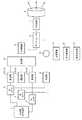
レーザレーダ装置は、図1に示すように、多波長光発振部1、複数の光カプラ2、複数の変調部3、合波部4、光増幅部5、サーキュレータ6、分合波器7、送受信光学系(送受信部)8、合波部9、合波カプラ10、光受信器11、信号解析部12及び保存表示部13から構成されている。Hereinafter, embodiments of the present invention will be described in detail with reference to the drawings.
Embodiment 1 FIG.
FIG. 1 is a block diagram showing a configuration of a laser radar apparatus according to Embodiment 1 of the present invention.
As shown in FIG. 1, the laser radar apparatus includes a multi-wavelength light oscillating unit 1, a plurality of
多波長光発振部1は、互いに異なる波長の複数の光(レーザ)を発振するものである。なお図1の例では、多波長光発振部1により発振される光は3本としているが、2本以上であれば何本でもよい。この多波長光発振部1により発振された各光はそれぞれ対応する光カプラ2に出力される。 The multi-wavelength light oscillator 1 oscillates a plurality of lights (lasers) having different wavelengths. In the example of FIG. 1, the number of lights oscillated by the multi-wavelength light oscillating unit 1 is three, but any number may be used as long as it is two or more. Each light oscillated by the multi-wavelength light oscillating unit 1 is output to the corresponding
光カプラ2は、多波長光発振部1からの光を2つに分配するものである。この光カプラ2により分配された一方の光は、送信光として用いられるものであり、対応する変調部3に出力される。また、光カプラ2により分配された他方の光は、光受信器11でヘテロダイン検波を行う際に用いられるものであり、合波部9に出力される。 The
変調部3は、光カプラ2からの光に対し、送受信光学系8で射出する視線方向により変調周波数(中心周波数)を変更して変調(パルス変調)を行うものである。この変調部3としては、例えばAOM(Acousto−Optic Modulator)及びAO周波数シフタを用いた構成が挙げられる。また、変調部3を図2のように構成してもよい。 The
図2に示す変調部3では、直線位相変調信号発生部31、光位相変調部32、パルス信号発生部33及び光強度変調部34を備えている。
直線位相変調信号発生部31は、任意の周期の鋸波を発生するものである。この直線位相変調信号発生部31は、ファンクションジェネレータ等で構成される。
光位相変調部32は、直線位相変調信号発生部31により発生された鋸波に従い、光カプラ2からの光に対して位相変調を行うものである。これにより、光の周波数をシフトする。なお、この際の周波数シフト量は、各変調部3においてそれぞれ任意の間隔で周波数をずらして設定する。
パルス信号発生部33は、光強度変調部34をON又はOFFするパルス信号を発生するものである。
光強度変調部34は、パルス信号発生部33により発生されたパルス信号に応じて駆動し、光位相変調部32により位相変調された光に対してパルス変調を行うものである。この光強度変調部34は、LN(Lithium Niobate)変調器又はMEMS光スイッチ等から構成される。
この変調部3によりパルス変調された光は合波部4に出力される。The
The linear phase
The optical
The
The
The light pulse-modulated by the
合波部4は、各変調部3からの光を合波するものである。この合波部4により合波された光は光増幅部5に出力される。 The multiplexing unit 4 combines the light from each
光増幅部5は、合波部4からの光を増幅するものである。なお、この光増幅部5は、用途によって又は多波長光発振部1での光出力が高い場合には不要であり、必須の構成ではない。この光増幅部5により増幅された光はサーキュレータ6を介して分合波器7に出力される。 The
サーキュレータ6は、入力光に応じて出力先を切替えるものである。ここで、サーキュレータ6は、光増幅部5からの光が入力された場合には、当該光を分合波器7に出力する。一方、分合波器7からの光が入力された場合には、当該光を合波カプラ10に出力する。 The
分合波器7は、サーキュレータ6を介した光増幅部5からの光を波長毎に分波し、また、送受信光学系8からの光を合波するものである。この分合波器7としては、WDM(Wavelength Division Multiplexer)等を用いることができる。ファブリペロー干渉計等でも実現可能であるが、従来一般的に通信用とで用いられるWDMを用いることで低損失となり、また、コストが低減できる。ただし、波長又は周波数で弁別できるものであればこれらに限るものではない。この分合波器7により分波された光は送受信光学系8に出力される。また、分合波器7により合波された光はサーキュレータ6を介して合波カプラ10に出力される。 The
送受信光学系8は、分合波器7からの光を対応する視線方向に射出し、エアロゾルにより反射された光を受信するものである。この送受信光学系8は、単体又は複数の望遠鏡で構成される。単体の望遠鏡の場合には、レンズに対するファイバの設置位置及び角度等で光の射出角度及び入射角度を変更するようにしてもよく、また、波長により光の射出方向を変化させる回折格子を用いてもよい。この送受信光学系8により受信された光は分合波器7に出力される。 The transmission / reception
合波部9は、各光カプラ2からの光を合波するものである。この合波部9により合波された光は合波カプラ10に出力される。 The
合波カプラ10は、合波部9からの光と、サーキュレータ6を介した分合波器7からの光とを合波するものである。 The multiplexing
光受信器11は、合波カプラ10からの光(多波長光発振部1により発振された光と、送受信光学系8により受信された対応する光)を用いてヘテロダイン検波を行い、各視線方向に対するビート信号を検出するものである。この光受信器11としては、バランスドレシーバを用いる。この光受信器11により検出された各ビート信号は信号解析部12に出力される。 The
信号解析部12は、光受信器11からの各ビート信号から各視線方向のドップラ風速値を算出し、当該ドップラ風速値を用いて3次元風速値を算出するものである。この信号解析部12は、図3に示すように、A/D(Analog to Digital)変換部121、FFT(Fast Fourier Transform)処理部122、インコヒーレント積算部123、視線風速算出部124及び風速ベクトル算出部125を備えている。この信号解析部12の各部は、ソフトウェアに基づくCPUを用いたプログラム処理によって実行される。 The
A/D変換部121は、光受信器11からの各ビート信号をA/D変換するものである。
FFT処理部122は、A/D変換部121によりA/D変換された各信号に対しFFT処理を行うものである。
インコヒーレント積算部123は、FFT処理部122によりFFT処理された各信号をインコヒーレント積分するものである。
視線風速算出部124は、インコヒーレント積算部123によりインコヒーレント積分された信号から、ピーク検出又は受信演算等を行ってドップラ周波数を算出し、当該ドップラ周波数から各視線方向のドップラ風速値を算出するものである。
風速ベクトル算出部125は、視線風速算出部124により算出された多方向のドップラ風速値から3次元風速値(水平方向又は鉛直方向の風速値)を算出するものである。
この信号解析部12による算出結果を示すデータは保存表示部13に出力される。The A /
The
The incoherent integration unit 123 performs incoherent integration of each signal subjected to the FFT processing by the
The line-of-sight wind speed calculation unit 124 calculates the Doppler frequency from the signal incoherently integrated by the incoherent integration unit 123 by performing peak detection or reception calculation, and calculates the Doppler wind speed value in each line-of-sight direction from the Doppler frequency. Is.
The wind speed vector calculation unit 125 calculates a three-dimensional wind speed value (horizontal or vertical wind speed value) from the multidirectional Doppler wind speed values calculated by the line-of-sight wind speed calculation unit 124.
Data indicating the calculation result by the
保存表示部13は、信号解析部12からのデータを保存し、また、モニタ(不図示)上に表示するものである。この保存表示部13は、例えばRAM又はハードディスク等の記憶装置と、GPU(Graphics Processing Unit)及びディスプレイ等とから構成されている。 The
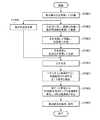
次に、上記のように構成されたレーザレーダ装置の動作について、図4を参照しながら説明する。
レーザレーダ装置の動作では、図4に示すように、まず、多波長光発振部1は互いに異なる波長の複数の光を発振し、各光カプラ2は対応する光を2つに分配する(ステップST401)。この各光カプラ2により分配された一方の光は対応する変調部3に出力され、他方の光は合波部9に出力される。Next, the operation of the laser radar apparatus configured as described above will be described with reference to FIG.
In the operation of the laser radar device, as shown in FIG. 4, first, the multi-wavelength light oscillating unit 1 oscillates a plurality of lights having mutually different wavelengths, and each
次いで、各変調部3は、対応する光カプラ2からの光に対し、送受信光学系8で射出する視線方向により変調周波数を変更してパルス変調を行う(ステップST402)。すなわち、図1に示す各変調部3−1〜3−3において、例えば図5に示すように、それぞれ異なる変調周波数IF1〜IF3で強度変調を行う。このように、光の視線方向毎に変調周波数を変えることで、信号解析部12で得られた信号がどの方位からの信号であるかを弁別することが可能となり、多方向の同時観測が可能となる。この各変調部3によりパルス変調された光は合波部4に出力される。 Next, each
次いで、合波部4は各変調部3からの光を合波し、光増幅部5は合波された光を増幅し、分合波器7は増幅された光を波長毎に分波する(ステップST403)。ここで、光増幅部5及びサーキュレータ6の前後に合波部4と分合波器7を設けることで、光増幅部5及びサーキュレータ6を波長毎に用意する必要がなくなり、1台ずつとすることができる。よって、装置の小型化及び低コスト化に寄与できる。なお、光増幅部5が不要の場合には増幅処理は行われない。この分合波器7により分波された光は送受信光学系8に出力される。 Next, the multiplexing unit 4 combines the light from each
次いで、送受信光学系8は分合波器7からの各光を対応する視線方向に射出してエアロゾルにより反射された光を受信し、分合波器7は受信された各光を合波する(ステップST404)。この分合波器7により合波された光はサーキュレータ6を介して合波カプラ10に出力される。 Next, the transmission / reception
一方、合波部9は、各光カプラ2からの光を合波する(ステップST405)。ここで、合波カプラ10及び光受信器11の前段に合波部9を設けることで、合波カプラ10及び光受信器11を波長毎に用意する必要がなくなり、1台ずつとすることができる。また、光受信器11では、ヘテロダイン検波を行う場合に、各波長同士でしかビート信号を検出できない特性があるため、本構成とすることで装置の小型化及び低コスト化に寄与できる。この合波部9により合波された光は合波カプラ10に出力される。 On the other hand, the
次いで、合波カプラ10は、合波部9からの光と、サーキュレータ6を介した分合波器7からの光とを合波する(ステップST406)。この合波カプラ10により合波された光は光受信器11に出力される。 Next, the multiplexing
次いで、光受信器11は、合波カプラ10からの光を用いてヘテロダイン検波を行い、各視線方向に対するビート信号を検出する(ステップST407)。この光受信器11により検出された各ビート信号は信号解析部12に出力される。 Next, the
次いで、信号解析部12は、光受信器11からの各ビート信号から各視線方向のドップラ風速値を算出し、当該ドップラ風速値から3次元風速値を算出する(ステップST408)。以下に、信号解析部12での動作を示す。 Next, the
信号解析部12では、まず、A/D変換部121は光受信器11からの各ビート信号をA/D変換し、FFT処理部122はA/D変換された各信号に対しFFT処理を行う。すなわち、A/D変換された広帯域の信号に対してFFT処理を行うことで、IF±fwの周波数帯域幅を各視線方向のスペクトルデータとして取得する。これにより、信号解析部12内で視線方向毎に信号を弁別することができる。なお、各チャネルが占有するスペクトルデータの周波数帯域幅は、IF+2fw+α(αはマージン値)等でも設定が可能である。 In the
また、この際のfwは、取得したい風速値の片側幅vw及び波長λより下式(1)で算出できる。なお、風速値の片側幅とは、例えば取得したい風速値が±30m/sの場合、その絶対値30を指す。
一方、エアロゾルをターゲットとした観測では後方散乱係数が低いため、積算することによりSNRを向上させることが必須となる。そのため、インコヒーレント積算部123は、FFT処理部122によりFFT処理された各信号(1以上のスペクトルデータ)をインコヒーレント積分する。なお、FFT処理部122で取得されたスペクトルデータのSNR値によっては、インコヒーレント積算部123による処理を省略してもよい。 On the other hand, since observation with aerosol as a target has a low backscattering coefficient, it is essential to improve SNR by integration. Therefore, the incoherent integration unit 123 incoherently integrates each signal (one or more spectrum data) subjected to the FFT processing by the
次いで、視線風速算出部124は、インコヒーレント積算部123によりインコヒーレント積分された信号から、ピーク検出又は受信演算等を行ってドップラ周波数を算出し、当該ドップラ周波数から各視線方向のドップラ風速値を算出する。なお、ドップラ風速値vlos(m/s)は、ドップラ周波数fd(Hz)及び波長λを用いて下式(2)で算出できる。
vlos=λ×fd (2)Next, the line-of-sight wind speed calculation unit 124 calculates the Doppler frequency from the signal incoherently integrated by the incoherent integration unit 123 by performing peak detection or reception calculation, and calculates the Doppler wind speed value in each line-of-sight direction from the Doppler frequency. calculate. The Doppler wind speed value vlos (m / s) can be calculated by the following equation (2) using the Doppler frequency fd (Hz) and the wavelength λ.
vlos = λ × fd (2)
次いで、風速ベクトル算出部125は、視線風速算出部124により算出された多方向のドップラ風速値から3次元風速値を算出する。
なお、上記動作に限らず、例えば特許文献1のように、取得されるSNRによって信号処理手法を変更してもよい。
この信号解析部12による算出結果を示すデータは保存表示部13に出力される。Next, the wind speed vector calculation unit 125 calculates a three-dimensional wind speed value from the multi-directional Doppler wind speed value calculated by the line-of-sight wind speed calculation unit 124.
Note that the signal processing method may be changed depending on the acquired SNR, for example, as in Patent Document 1 without being limited to the above operation.
Data indicating the calculation result by the
次いで、保存表示部13は、信号解析部12からのデータを保存し、また、モニタ(不図示)上に表示する(ステップST409)。 Next, the
以上のように、この実施の形態1によれば、互いに異なる波長の複数の光を発振し、この光に対し、射出する視線方向により変調周波数を変更して変調を行うように構成したので、光を走査するのではなく、同時に光を多方向に射出することで、多方向の風速値を同時に観測することできる。その結果、乱流場であっても風速測定精度の劣化を低減することが可能となり、また、風速測定レートを向上させることが可能となる。 As described above, according to the first embodiment, a plurality of lights having different wavelengths are oscillated, and the modulation is performed by changing the modulation frequency according to the direction of the line of sight emitted from the light. Rather than scanning light, by emitting light in multiple directions at the same time, wind speed values in multiple directions can be observed simultaneously. As a result, it is possible to reduce the deterioration of the wind speed measurement accuracy even in a turbulent flow field, and to improve the wind speed measurement rate.
なお、送受信光学系8及び信号解析部12において、例えば特許文献2のように取得された距離−SNRプロファイルを用いて集光距離を変更する構成としてもよい。これにより、データ取得率が向上する。 Note that the transmission / reception
実施の形態2.
実施の形態2では、同時多方向の風速測定ではなく、従来とは異なった走査方式を行うことで、風速測定精度を改善する方式を示す。
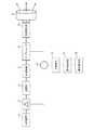
図6はこの発明の実施の形態2に係るレーザレーダ装置の構成を示す図である。この図6に示す実施の形態2に係るレーザレーダ装置は、図1に示す実施の形態1に係るレーザレーダ装置の多波長光発振部1を光発振部14に変更し、複数の光カプラ2及び変調部3を単一の光カプラ2及び変調部3とし、合波部4、分合波器7及び合波部9を削除し、光切替え部15を追加したものである。その他の構成は同様であり、同一の符号を付して異なる部分についてのみ説明を行う。
In the second embodiment, a method of improving wind speed measurement accuracy by performing a scanning method different from the conventional one instead of simultaneous multidirectional wind speed measurement will be described.
6 is a diagram showing a configuration of a laser radar apparatus according to
光発振部14は、単一の波長の光(ビーム)を発振するものである。この光発振部14により発振された光は光カプラ2に出力される。 The
光切替え部15は、サーキュレータ6を介した光増幅部5からの光を射出する視線方向を、各回で切替えて選択するものである。そして、上記光を、選択した視線方向への経路を介して送受信光学系8に出力する。この光切替え部15は、光スイッチにより構成される。また、高速走査が可能なウェッジスキャナ等でも代替可能である。
そして、送受信光学系8は、光切替え部15からの光を当該光切替え部15により選択された視線方向に射出する。The
Then, the transmission / reception
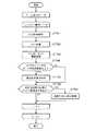
また、信号解析部12では、実施の形態1と異なり同時に多方向に対するビート信号は得られず、各視線方向に対するビート信号が順次入力される。以下、実施の形態2に係る信号解析部12での動作について、図7を参照しながら説明する。 Further, unlike the first embodiment, the
実施の形態2における信号解析部12では、まず、A/D変換部121は光受信器11からのビート信号をA/D変換し、FFT処理部122はA/D変換された信号に対しFFT処理を行う(ステップST701,702)。 In the
次いで、インコヒーレント積算部123は、FFT処理部122によりFFT処理された信号(1以上のスペクトルデータ)をインコヒーレント積分する(ステップST703)。なお、FFT処理部122で取得されたスペクトルデータのSNR値によっては、インコヒーレント積算部123による処理を省略してもよい。 Next, the incoherent integration unit 123 performs incoherent integration on the signal (one or more spectrum data) subjected to the FFT processing by the FFT processing unit 122 (step ST703). Depending on the SNR value of the spectrum data acquired by the
次いで、視線風速算出部124は、インコヒーレント積算部123によりインコヒーレント積分された信号(スペクトルデータ)のピークがSNR閾値以上かどうかを判断する(ステップST704)。 Next, the line-of-sight wind speed calculation unit 124 determines whether or not the peak of the signal (spectral data) incoherently integrated by the incoherent integration unit 123 is greater than or equal to the SNR threshold (step ST704).
このステップST704において、視線風速算出部124は、スペクトルデータのピークがSNR閾値以上であると判断した場合には、本レンジビン且つ視線方向のスペクトル強度は十分であるものとし、ドップラ風速値を算出する(ステップST705)。この際、スペクトルデータに対してピーク検出又は重心演算等を行ってドップラ周波数を算出する。そして、算出されたドップラ周波数fdに対し、例えば下式(3)によりドップラ風速値vlosを算出する。なお、λは波長である。
vlos=λ×fd (3)In step ST704, when the line-of-sight wind speed calculation unit 124 determines that the peak of the spectrum data is greater than or equal to the SNR threshold, the line-of-range bin and the line-of-sight direction spectral intensity are assumed to be sufficient, and the Doppler wind speed value is calculated. (Step ST705). At this time, the Doppler frequency is calculated by performing peak detection or gravity center calculation on the spectrum data. Then, for the calculated Doppler frequency fd, a Doppler wind speed value vlos is calculated by the following equation (3), for example. Note that λ is a wavelength.
vlos = λ × fd (3)
一方、ステップST704において、視線風速算出部124は、スペクトルデータのピークがSNR閾値より低いと判断した場合には、ドップラ風速値の算出は行わない。 On the other hand, if the line-of-sight wind speed calculation unit 124 determines in step ST704 that the peak of the spectrum data is lower than the SNR threshold, it does not calculate the Doppler wind speed value.
次いで、風速ベクトル算出部125は、3次元風速値を算出するのに必要な視線方向数のドップラ風速値が揃っているかを判断する(ステップST706)。
このステップST706において、風速ベクトル算出部125が、3次元風速値を算出するのに必要な視線方向数のドップラ風速値が揃っていると判断した場合には、この多方向のドップラ風速値から3次元風速値を算出する(ステップST707)。Next, the wind speed vector calculation unit 125 determines whether the Doppler wind speed values for the number of line-of-sight directions necessary for calculating the three-dimensional wind speed value are aligned (step ST706).
In step ST706, when the wind speed vector calculation unit 125 determines that the Doppler wind speed values for the number of line-of-sight directions necessary for calculating the three-dimensional wind speed value are prepared, 3 is calculated from the multi-directional Doppler wind speed values. A dimensional wind speed value is calculated (step ST707).
一方、ステップST706において、風速ベクトル算出部125が、3次元風速値を算出するのに必要な視線方向数のドップラ風速値が揃っていないと判断した場合には、3次元風速値の算出は行わない。その後、次のレンジビン、次の視線方向に対する処理へ移行する。 On the other hand, when the wind speed vector calculation unit 125 determines in step ST706 that the Doppler wind speed values for the number of line-of-sight directions necessary for calculating the three-dimensional wind speed values are not complete, the three-dimensional wind speed value is calculated. Absent. Thereafter, the process proceeds to the next range bin and the next line-of-sight direction.
このように、それぞれのレンジビンにおいて、必要最小限の信号量(SNR)をインコヒーレント積算により取得することで、風速測定レートを最大限に高速化することができる。よって、風速測定精度を向上させることができる。 As described above, in each range bin, the necessary minimum signal amount (SNR) is obtained by incoherent integration, so that the wind speed measurement rate can be maximized. Therefore, the wind speed measurement accuracy can be improved.
一方、例えば特許文献3に示す従来構成では、固定のインコヒーレント積算を事前に定義し、その積算数になるまでその視線方向のデータを取得した後、視線方向の方向を切替えていた。すなわち、図8(a)に示すように、1つの視線方向に対して複数回観測を行った後、次の視線方向に切替えるよう走査を行っていた。この走査方式によるとエアロゾル量が多く、積算数が少なくとも風速測定が可能な場合においても、余剰に観測時間をかけてしまう。また、各視線方向での観測時間が長いと、図9に示すような問題が生じる。 On the other hand, for example, in the conventional configuration shown in
図9(a)は、従来のレーザレーダ装置901で観測を行う視線方向801a〜801eを示している。なお、符号802は観測を行う風であり、下降流及び上昇流が発生している。また、図9(b)は、視線方向801b,801dの観測時の観測ポイント902b,902dを示している。また、図9(c)は、視線方向801b,801dでのスペクトル903b,903d及び重心演算結果904b,904dを示している。
図9に示す例の場合、実際には風802の水平方向の風速は小さい。しかしながら、従来の一般的なベクトル演算による水平方向の風速演算式は、下式(4)の通りであり、大きい水平方向の風速値が算出されてしまう。これは、風速ベクトル演算の前提条件である風速及び風向の一様性がないためである。
V=(v2−v4)/sinθ (4)
なお、Vは水平方向の風速値、vは視線方向の風速値、θは天頂角、添え字はビーム番号であり視線方向801bの方向を正とする。FIG. 9A shows line-of-
In the case of the example shown in FIG. 9, the wind speed of the
V = (v2 −v4 ) / sin θ (4)
Note that V is a wind speed value in the horizontal direction, v is a wind speed value in the viewing direction, θ is a zenith angle, a subscript is a beam number, and the direction in the
一方、図10(a)は、本発明のレーザレーダ装置1001で観測を行う視線方向801a〜801eを示している。なお、符号802は観測を行う風であり、下降流及び上昇流が発生している。また、図10(b)は、視線方向801bの観測時の観測ポイント1002bを示している。また、図10(c)は、視線方向801bでのスペクトル1003b及び重心演算結果1004bを示している。
この図10(b)に示すように、本発明の走査方式(図8(b))では、風802の上昇流と下降流の風速値を離散的にサンプルすることができる。その結果、図10(c)に示すように、得られるスペクトルデータはダブルピークのような形状をとる。そして、このスペクトルデータに対し、重心演算を行うことで中間的な風速値を得ることができる。その結果、上記従来方式と比較して風速測定誤差を低減させることが可能となる。このとき、ダブルピークを最尤推定法等で検知し、平均的な風速値を算出してもよい。On the other hand, FIG. 10A shows line-of-
As shown in FIG. 10 (b), in the scanning method of the present invention (FIG. 8 (b)), the wind speed values of the upflow and downflow of the
以上のように、この実施の形態2によれば、各回において視線方向を切替える走査方式としたので、視線方向を複数回置きに切替えるのではなく、毎回切替えることで、風速測定レートが向上する。その結果、乱流場であっても風速測定精度の劣化を低減することが可能となる。 As described above, according to the second embodiment, since the scanning method is used to switch the line-of-sight direction each time, the wind speed measurement rate is improved by switching the line-of-sight direction every time, instead of switching every time. As a result, it is possible to reduce deterioration in wind speed measurement accuracy even in a turbulent flow field.
実施の形態3.
実施の形態1の視線風速算出部124では、図7に示す実施の形態2のように、インコヒーレント積算された信号のSNR値の確認は行っていないが、これを行うようにしてもよい。これにより、各レンジビンにおいて、必要最小数のインコヒーレント積算を行わせることができ、さらに風速測定レートを高速化させることが可能となり、風速測定精度を向上させることができる。
The line-of-sight wind speed calculation unit 124 according to the first embodiment does not check the SNR value of the incoherently integrated signal as in the second embodiment illustrated in FIG. 7, but may perform this. As a result, the minimum number of incoherent integrations can be performed in each range bin, the wind speed measurement rate can be increased, and the wind speed measurement accuracy can be improved.
なお、本願発明はその発明の範囲内において、各実施の形態の自由な組み合わせ、あるいは各実施の形態の任意の構成要素の変形、もしくは各実施の形態において任意の構成要素の省略が可能である。 In the present invention, within the scope of the invention, any combination of the embodiments, or any modification of any component in each embodiment, or omission of any component in each embodiment is possible. .
この発明に係るレーザレーダ装置は、乱流場であっても風速測定精度の劣化を低減することができ、観測領域における風速値を計測するレーザレーダ装置等に用いるのに適している。 The laser radar device according to the present invention can reduce deterioration of wind speed measurement accuracy even in a turbulent flow field, and is suitable for use in a laser radar device or the like that measures a wind speed value in an observation region.
1 多波長光発振部、2 光カプラ、3 変調部、4 合波部、5 光増幅部、6 サーキュレータ、7 分合波器、8 送受信光学系(送受信部)、9 合波部、10 合波カプラ、11 光受信器、12 信号解析部、13 保存表示部、14 光発振部、15 光切替え部、31 直線位相変調信号発生部、32 光位相変調部、33 パルス信号発生部、34 光強度変調部、121 A/D変換部、122 FFT処理部、123 インコヒーレント積算部、124 視線風速算出部、125 風速ベクトル算出部。 1 Multi-wavelength optical oscillation unit, 2 optical coupler, 3 modulation unit, 4 multiplexing unit, 5 optical amplification unit, 6 circulator, 7 multiplexer / demultiplexer, 8 transmission / reception optical system (transmission / reception unit), 9 multiplexing unit, 10 coupling Wave coupler, 11 optical receiver, 12 signal analysis unit, 13 storage display unit, 14 optical oscillation unit, 15 optical switching unit, 31 linear phase modulation signal generation unit, 32 optical phase modulation unit, 33 pulse signal generation unit, 34 light Intensity modulation unit, 121 A / D conversion unit, 122 FFT processing unit, 123 incoherent integration unit, 124 line-of-sight wind speed calculation unit, 125 wind speed vector calculation unit.
Claims (2)
Translated fromJapanese前記多波長光発振部により発振された対応する光に対し、射出する視線方向により変調周波数を変更して変調を行う複数の変調部と、
各々の前記変調部により変調された光を対応する視線方向に射出し、反射された光を受信する送受信部と、
前記多波長光発振部により発振された光と前記送受信部により受信された対応する光を用いてヘテロダイン検波を行い、各視線方向に対するビート信号を検出する光受信器と、
前記光受信器により検出された各ビート信号から各視線方向のドップラ風速値を算出し、当該ドップラ風速値を用いて3次元風速値を算出する信号解析部と
を備えたレーザレーダ装置。A multi-wavelength light oscillating unit that oscillates a plurality of lights having different wavelengths;
A plurality of modulators that modulate the corresponding light oscillated by the multi-wavelength light oscillator by changing the modulation frequency according to the line-of-sight direction to be emitted;
A transmission / reception unit that emits light modulated by each of the modulation units in a corresponding line-of-sight direction and receives reflected light; and
An optical receiver that performs heterodyne detection using the light oscillated by the multi-wavelength light oscillating unit and the corresponding light received by the transceiver unit, and detects a beat signal for each line-of-sight direction;
A laser radar apparatus comprising: a signal analysis unit that calculates a Doppler wind speed value in each line-of-sight direction from each beat signal detected by the optical receiver, and calculates a three-dimensional wind speed value using the Doppler wind speed value.
前記光発振部により発振された光に対し、変調を行う変調部と、
前記変調部により変調された光を射出する視線方向を、各回で切替えて選択する光切替え部と、
前記変調部により変調された光を前記光切替え部により選択された視線方向に射出し、反射された光を受信する送受信部と、
前記光発振部により発振された光と前記送受信部により受信された光を用いてヘテロダイン検波を行い、該当する視線方向に対するビート信号を検出する光受信器と、
前記光受信器により検出されたビート信号から該当する視線方向のドップラ風速値を算出し、当該ドップラ風速値を用いて3次元風速値を算出する信号解析部と
を備えたレーザレーダ装置。An optical oscillation unit that oscillates light;
A modulation unit that modulates the light oscillated by the light oscillation unit;
A light switching unit that selects a line-of-sight direction that emits light modulated by the modulation unit by switching each time; and
A transmission / reception unit that emits light modulated by the modulation unit in a line-of-sight direction selected by the light switching unit, and receives reflected light;
An optical receiver that performs heterodyne detection using the light oscillated by the optical oscillating unit and the light received by the transmitting / receiving unit, and detects a beat signal with respect to a corresponding line-of-sight direction;
A laser radar apparatus comprising: a signal analysis unit that calculates a Doppler wind speed value in a corresponding line-of-sight direction from a beat signal detected by the optical receiver, and calculates a three-dimensional wind speed value using the Doppler wind speed value.
Applications Claiming Priority (1)
| Application Number | Priority Date | Filing Date | Title |
|---|---|---|---|
| PCT/JP2014/083022WO2016092705A1 (en) | 2014-12-12 | 2014-12-12 | Laser radar device |
Publications (1)
| Publication Number | Publication Date |
|---|---|
| JPWO2016092705A1true JPWO2016092705A1 (en) | 2017-04-27 |
Family
ID=56106949
Family Applications (1)
| Application Number | Title | Priority Date | Filing Date |
|---|---|---|---|
| JP2016563383APendingJPWO2016092705A1 (en) | 2014-12-12 | 2014-12-12 | Laser radar equipment |
Country Status (5)
| Country | Link |
|---|---|
| US (1) | US20170307648A1 (en) |
| EP (1) | EP3232226A4 (en) |
| JP (1) | JPWO2016092705A1 (en) |
| CN (1) | CN107003411A (en) |
| WO (1) | WO2016092705A1 (en) |
Families Citing this family (40)
| Publication number | Priority date | Publication date | Assignee | Title |
|---|---|---|---|---|
| US9977188B2 (en) | 2011-08-30 | 2018-05-22 | Skorpios Technologies, Inc. | Integrated photonics mode expander |
| WO2015183992A1 (en)* | 2014-05-27 | 2015-12-03 | Skorpios Technologies, Inc. | Waveguide mode expander using amorphous silicon |
| JPWO2018061106A1 (en)* | 2016-09-28 | 2018-09-27 | 三菱電機株式会社 | Laser radar equipment |
| CN106443707B (en)* | 2016-10-17 | 2023-10-31 | 中国科学院光电研究院 | A hyperspectral lidar system and its control method |
| WO2019008670A1 (en)* | 2017-07-04 | 2019-01-10 | 三菱電機株式会社 | Laser radar device |
| EP3683600B1 (en)* | 2017-12-27 | 2022-08-24 | Mitsubishi Electric Corporation | Laser radar device |
| DE102018200618A1 (en)* | 2018-01-16 | 2019-07-18 | Robert Bosch Gmbh | sensor device |
| US11650296B2 (en)* | 2018-02-16 | 2023-05-16 | Xiaotian Steve Yao | Optical sensing based on wavelength division multiplexed (WDM) light at different wavelengths in light detection and ranging LiDAR systems |
| US10795054B2 (en)* | 2018-03-20 | 2020-10-06 | Mitsubishi Electric Research Laboratories, Inc. | System and method for sensing wind flow passing over complex terrain |
| WO2019180924A1 (en)* | 2018-03-23 | 2019-09-26 | 三菱電機株式会社 | Laser radar device |
| US10901089B2 (en)* | 2018-03-26 | 2021-01-26 | Huawei Technologies Co., Ltd. | Coherent LIDAR method and apparatus |
| US11933903B2 (en)* | 2018-03-29 | 2024-03-19 | Mitsubishi Electric Corporation | Laser radar device |
| CN108572360A (en)* | 2018-04-27 | 2018-09-25 | 北京工业大学 | A receiving device for multi-wavelength laser radar |
| CN108562887A (en)* | 2018-04-27 | 2018-09-21 | 北京工业大学 | A kind of multi-wavelength laser radar based on wavelength-division multiplex |
| CN108828615B (en)* | 2018-06-11 | 2024-07-26 | 深圳市镭神智能系统有限公司 | Light emitting unit, optical system, and laser radar system |
| US11536805B2 (en) | 2018-06-25 | 2022-12-27 | Silc Technologies, Inc. | Optical switching for tuning direction of LIDAR output signals |
| CN108594265A (en)* | 2018-08-02 | 2018-09-28 | 成都英鑫光电科技有限公司 | Windfinding radar system and dimensional wind detection method |
| CN109342763A (en)* | 2018-10-22 | 2019-02-15 | 国家海洋局第海洋研究所 | An all-fiber wind speed measurement system based on three-axis laser |
| CA3100885C (en)* | 2018-12-03 | 2022-03-15 | Nanjing Movelaser Technology Co., Ltd. | Wind field information measurement method and nacelle-based lidar |
| JP7193716B2 (en)* | 2018-12-10 | 2022-12-21 | 日本電信電話株式会社 | Wireless communication system, master station device and wireless communication method |
| EP3955028A4 (en)* | 2019-04-08 | 2022-08-31 | Mitsubishi Electric Corporation | LIDAR DEVICE FOR WIND MEASUREMENT |
| US12429569B2 (en) | 2019-05-17 | 2025-09-30 | Silc Technologies, Inc. | Identification of materials illuminated by LIDAR systems |
| FR3096788B1 (en)* | 2019-05-29 | 2021-06-11 | Thales Sa | LIDAR SYSTEM INCLUDING AN INTERFERENTIAL DIFFRACTIVE ELEMENT AND LIDAR IMAGING PROCESS |
| US11650317B2 (en) | 2019-06-28 | 2023-05-16 | Silc Technologies, Inc. | Use of frequency offsets in generation of LIDAR data |
| CN110308454B (en)* | 2019-07-08 | 2021-04-16 | 中国科学院合肥物质科学研究院 | Wind speed measurement system and method of quasi-non-blind-area Doppler coherent laser radar |
| CN110456382B (en)* | 2019-07-12 | 2023-02-21 | 中国海洋大学 | Measurement method of wind vector in non-uniform wind field based on single-Doppler lidar |
| CN110927737A (en)* | 2019-11-26 | 2020-03-27 | 华中科技大学 | Multi-frequency modulation laser dynamic target distance and speed measurement system and method |
| EP3842826A1 (en)* | 2019-12-23 | 2021-06-30 | Yandex Self Driving Group LLC | Lidar detection methods and systems with fbg filter |
| US11585930B2 (en)* | 2020-02-06 | 2023-02-21 | Honeywell International Inc. | Silicon photonics integrated optical velocimeter |
| US12306344B1 (en)* | 2020-08-25 | 2025-05-20 | Silc Technologies, Inc. | Reduction of components in LIDAR systems |
| US12429746B2 (en) | 2020-10-20 | 2025-09-30 | Xiaotian Steve Yao | Optical beam scanning based on waveguide switching and position-to-angle conversion of a lens and applications |
| EP4044172A1 (en)* | 2021-02-15 | 2022-08-17 | Furuno Electric Co., Ltd. | Target detection device and target detection method |
| EP4283338B1 (en)* | 2021-02-26 | 2025-09-17 | Mitsubishi Electric Corporation | Signal processing device and signal processing method |
| CN113176581B (en)* | 2021-03-15 | 2021-12-31 | 北京华信科创科技有限公司 | Doppler pulse laser wind measuring device, method and system |
| DE102021002239A1 (en)* | 2021-04-28 | 2022-11-03 | Leonardo Germany Gmbh | Doppler lidar for detecting wind and/or vortex situations |
| US12411213B2 (en) | 2021-10-11 | 2025-09-09 | Silc Technologies, Inc. | Separation of light signals in a LIDAR system |
| CN114839644A (en)* | 2022-05-19 | 2022-08-02 | 哈尔滨工业大学(深圳) | Laser radar system |
| US12422618B2 (en) | 2022-10-13 | 2025-09-23 | Silc Technologies, Inc. | Buried taper with reflecting surface |
| CN115877352A (en)* | 2022-11-11 | 2023-03-31 | 中国航空工业集团公司西安飞行自动控制研究所 | Real-time large-dynamic Doppler velocity measurement laser radar device and method |
| CN118575100A (en)* | 2022-12-30 | 2024-08-30 | 深圳市镭神智能系统有限公司 | Laser measuring instrument, laser measuring method, electronic device and medium |
Citations (16)
| Publication number | Priority date | Publication date | Assignee | Title |
|---|---|---|---|---|
| JPS6117969A (en)* | 1984-07-04 | 1986-01-25 | Nec Corp | Radar equipment |
| JPH02132395A (en)* | 1988-11-14 | 1990-05-21 | Nippon Sheet Glass Co Ltd | Multidirectional laser doppler speed indicator |
| JP2004212274A (en)* | 2003-01-07 | 2004-07-29 | Mitsubishi Electric Corp | Wind speed vector measuring device and wind speed vector measuring method |
| JP2005351853A (en)* | 2004-06-14 | 2005-12-22 | Mitsubishi Electric Corp | Lightwave radar device |
| JP2006177853A (en)* | 2004-12-24 | 2006-07-06 | Mitsubishi Electric Corp | Wind measurement method and apparatus |
| JP2008039640A (en)* | 2006-08-08 | 2008-02-21 | Mitsubishi Electric Corp | Coherent rider device |
| JP2008309562A (en)* | 2007-06-13 | 2008-12-25 | Mitsubishi Electric Corp | Lightwave radar device |
| JP2010151806A (en)* | 2008-11-28 | 2010-07-08 | Mitsubishi Electric Corp | Receiving circuit for doppler radar, and doppler radar |
| JP2010256333A (en)* | 2009-04-02 | 2010-11-11 | Toshiba Corp | Meteorological radar apparatus and meteorological observation method |
| JP2011519424A (en)* | 2008-04-30 | 2011-07-07 | オプティカル エアー データ システムズ,エルエルシー | Laser doppler speedometer |
| US20110216307A1 (en)* | 2010-02-05 | 2011-09-08 | Catch the Wind, Inc. | High Density Wind Velocity Data Collection for Wind Turbine |
| US20130162976A1 (en)* | 2011-12-23 | 2013-06-27 | Optical Air Data Systems, Llc | High Power Laser Doppler Velocimeter With Multiple Amplification Stages |
| US20130250276A1 (en)* | 2011-02-14 | 2013-09-26 | Optical Air Data Systems, Llc | Laser Wind Velocimeter With Multiple Radiation Sources |
| WO2014024508A1 (en)* | 2012-08-08 | 2014-02-13 | 三菱電機株式会社 | Radar device |
| JP2014066548A (en)* | 2012-09-25 | 2014-04-17 | Mitsubishi Electric Corp | Laser radar device |
| WO2015087564A1 (en)* | 2013-12-10 | 2015-06-18 | 三菱電機株式会社 | Laser radar device |
Family Cites Families (11)
| Publication number | Priority date | Publication date | Assignee | Title |
|---|---|---|---|---|
| US5745437A (en)* | 1996-08-05 | 1998-04-28 | Wachter; Eric A. | Method and apparatus for coherent burst ranging |
| US20020075472A1 (en)* | 2000-09-22 | 2002-06-20 | Holton Carvel E. | Optical fiber ceilometer for meteorological cloud altitude sensing |
| US7777866B1 (en)* | 2006-07-25 | 2010-08-17 | Kyrazis Demos T | Fixed difference, dual beam laser Doppler velocimetry |
| AU2010299566A1 (en)* | 2009-09-28 | 2012-05-03 | Pentalum Technologies Ltd. | Methods, devices and systems for remote wind sensing |
| JP5242532B2 (en)* | 2009-10-16 | 2013-07-24 | 株式会社日立ハイテクノロジーズ | Inspection device |
| US20130100773A1 (en)* | 2011-10-21 | 2013-04-25 | Steven Robert Rogers | Wide-area wind velocity profiler |
| CN102749627B (en)* | 2012-06-02 | 2013-12-18 | 中国科学院武汉物理与数学研究所 | Full-height laser radar for detecting atmosphere wind field, temperature and density |
| US9188677B2 (en)* | 2013-05-01 | 2015-11-17 | Sandia Corporation | Imaging doppler lidar for wind turbine wake profiling |
| FR3022349B1 (en)* | 2014-06-13 | 2016-09-23 | Thales Sa | LIDAR DOPPLER WITH RELATIVE MEASUREMENT OF SPEED |
| CN104133216B (en)* | 2014-07-17 | 2016-06-08 | 北京无线电测量研究所 | A kind of radar detection method and device obtaining Low level wind profile |
| US9766262B2 (en)* | 2014-11-10 | 2017-09-19 | Raytheon Company | System and method for measuring doppler effect utilizing elastic and inelastic light scattering |
- 2014
- 2014-12-12CNCN201480083368.7Apatent/CN107003411A/enactivePending
- 2014-12-12EPEP14908007.9Apatent/EP3232226A4/ennot_activeWithdrawn
- 2014-12-12JPJP2016563383Apatent/JPWO2016092705A1/enactivePending
- 2014-12-12USUS15/517,194patent/US20170307648A1/ennot_activeAbandoned
- 2014-12-12WOPCT/JP2014/083022patent/WO2016092705A1/enactiveApplication Filing
Patent Citations (16)
| Publication number | Priority date | Publication date | Assignee | Title |
|---|---|---|---|---|
| JPS6117969A (en)* | 1984-07-04 | 1986-01-25 | Nec Corp | Radar equipment |
| JPH02132395A (en)* | 1988-11-14 | 1990-05-21 | Nippon Sheet Glass Co Ltd | Multidirectional laser doppler speed indicator |
| JP2004212274A (en)* | 2003-01-07 | 2004-07-29 | Mitsubishi Electric Corp | Wind speed vector measuring device and wind speed vector measuring method |
| JP2005351853A (en)* | 2004-06-14 | 2005-12-22 | Mitsubishi Electric Corp | Lightwave radar device |
| JP2006177853A (en)* | 2004-12-24 | 2006-07-06 | Mitsubishi Electric Corp | Wind measurement method and apparatus |
| JP2008039640A (en)* | 2006-08-08 | 2008-02-21 | Mitsubishi Electric Corp | Coherent rider device |
| JP2008309562A (en)* | 2007-06-13 | 2008-12-25 | Mitsubishi Electric Corp | Lightwave radar device |
| JP2011519424A (en)* | 2008-04-30 | 2011-07-07 | オプティカル エアー データ システムズ,エルエルシー | Laser doppler speedometer |
| JP2010151806A (en)* | 2008-11-28 | 2010-07-08 | Mitsubishi Electric Corp | Receiving circuit for doppler radar, and doppler radar |
| JP2010256333A (en)* | 2009-04-02 | 2010-11-11 | Toshiba Corp | Meteorological radar apparatus and meteorological observation method |
| US20110216307A1 (en)* | 2010-02-05 | 2011-09-08 | Catch the Wind, Inc. | High Density Wind Velocity Data Collection for Wind Turbine |
| US20130250276A1 (en)* | 2011-02-14 | 2013-09-26 | Optical Air Data Systems, Llc | Laser Wind Velocimeter With Multiple Radiation Sources |
| US20130162976A1 (en)* | 2011-12-23 | 2013-06-27 | Optical Air Data Systems, Llc | High Power Laser Doppler Velocimeter With Multiple Amplification Stages |
| WO2014024508A1 (en)* | 2012-08-08 | 2014-02-13 | 三菱電機株式会社 | Radar device |
| JP2014066548A (en)* | 2012-09-25 | 2014-04-17 | Mitsubishi Electric Corp | Laser radar device |
| WO2015087564A1 (en)* | 2013-12-10 | 2015-06-18 | 三菱電機株式会社 | Laser radar device |
Also Published As
| Publication number | Publication date |
|---|---|
| EP3232226A4 (en) | 2018-07-25 |
| EP3232226A1 (en) | 2017-10-18 |
| WO2016092705A1 (en) | 2016-06-16 |
| CN107003411A (en) | 2017-08-01 |
| US20170307648A1 (en) | 2017-10-26 |
Similar Documents
| Publication | Publication Date | Title |
|---|---|---|
| WO2016092705A1 (en) | Laser radar device | |
| JP6223644B1 (en) | Laser radar equipment | |
| JP6395958B1 (en) | Laser radar equipment | |
| JP5948035B2 (en) | Distributed optical fiber acoustic wave detector | |
| US20190018115A1 (en) | Lidar arrangement and lidar method | |
| Onori et al. | Coherent interferometric dual-frequency laser radar for precise range/Doppler measurement | |
| JP6157735B2 (en) | Laser radar equipment | |
| CN111971582B (en) | Laser radar device | |
| KR20190093603A (en) | Method and apparatus for Doppler detection and Doppler correction of optical chirp distance detection | |
| JP2011519424A5 (en) | ||
| JPWO2017175297A1 (en) | Laser radar equipment | |
| JP2013238474A (en) | Laser radar device | |
| CN117872313B (en) | A laser radar transmitting device, detection system and detection method | |
| JP5148420B2 (en) | Optical fiber testing equipment | |
| JP4053542B2 (en) | Laser radar equipment | |
| US20230273323A1 (en) | Laser radar device and wind measurement method | |
| CA3116282A1 (en) | Optical system including high performance optical receiver and method thereof | |
| JP5561679B2 (en) | Optical frequency domain reflection measurement method and optical frequency domain reflection measurement apparatus | |
| JP4225952B2 (en) | Micro vibration detector | |
| JP6226854B2 (en) | Optical pulse test apparatus and optical pulse test method | |
| Ting et al. | Quantum-enhanced Fourier-basis multibeam photon-counting lidar | |
| JP2011174760A (en) | Method and device of measuring reflection of optical frequency region |
Legal Events
| Date | Code | Title | Description |
|---|---|---|---|
| A521 | Request for written amendment filed | Free format text:JAPANESE INTERMEDIATE CODE: A523 Effective date:20161110 | |
| A621 | Written request for application examination | Free format text:JAPANESE INTERMEDIATE CODE: A621 Effective date:20161110 | |
| A131 | Notification of reasons for refusal | Free format text:JAPANESE INTERMEDIATE CODE: A131 Effective date:20171017 | |
| A521 | Request for written amendment filed | Free format text:JAPANESE INTERMEDIATE CODE: A523 Effective date:20171207 | |
| A131 | Notification of reasons for refusal | Free format text:JAPANESE INTERMEDIATE CODE: A131 Effective date:20180508 | |
| A521 | Request for written amendment filed | Free format text:JAPANESE INTERMEDIATE CODE: A523 Effective date:20180625 | |
| A02 | Decision of refusal | Free format text:JAPANESE INTERMEDIATE CODE: A02 Effective date:20180807 |