JPWO2016063348A1 - Bending mechanism and flexible medical device - Google Patents
Bending mechanism and flexible medical deviceDownload PDFInfo
- Publication number
- JPWO2016063348A1 JPWO2016063348A1JP2016554977AJP2016554977AJPWO2016063348A1JP WO2016063348 A1JPWO2016063348 A1JP WO2016063348A1JP 2016554977 AJP2016554977 AJP 2016554977AJP 2016554977 AJP2016554977 AJP 2016554977AJP WO2016063348 A1JPWO2016063348 A1JP WO2016063348A1
- Authority
- JP
- Japan
- Prior art keywords
- bending mechanism
- guide
- longitudinal axis
- plate portion
- mechanism according
- Prior art date
- Legal status (The legal status is an assumption and is not a legal conclusion. Google has not performed a legal analysis and makes no representation as to the accuracy of the status listed.)
- Ceased
Links
Images


Classifications
- B—PERFORMING OPERATIONS; TRANSPORTING
- B25—HAND TOOLS; PORTABLE POWER-DRIVEN TOOLS; MANIPULATORS
- B25J—MANIPULATORS; CHAMBERS PROVIDED WITH MANIPULATION DEVICES
- B25J17/00—Joints
- A—HUMAN NECESSITIES
- A61—MEDICAL OR VETERINARY SCIENCE; HYGIENE
- A61B—DIAGNOSIS; SURGERY; IDENTIFICATION
- A61B1/00—Instruments for performing medical examinations of the interior of cavities or tubes of the body by visual or photographical inspection, e.g. endoscopes; Illuminating arrangements therefor
- A61B1/005—Flexible endoscopes
- A61B1/0051—Flexible endoscopes with controlled bending of insertion part
- A61B1/0055—Constructional details of insertion parts, e.g. vertebral elements
- A—HUMAN NECESSITIES
- A61—MEDICAL OR VETERINARY SCIENCE; HYGIENE
- A61B—DIAGNOSIS; SURGERY; IDENTIFICATION
- A61B1/00—Instruments for performing medical examinations of the interior of cavities or tubes of the body by visual or photographical inspection, e.g. endoscopes; Illuminating arrangements therefor
- A61B1/005—Flexible endoscopes
- A61B1/008—Articulations
- A—HUMAN NECESSITIES
- A61—MEDICAL OR VETERINARY SCIENCE; HYGIENE
- A61B—DIAGNOSIS; SURGERY; IDENTIFICATION
- A61B1/00—Instruments for performing medical examinations of the interior of cavities or tubes of the body by visual or photographical inspection, e.g. endoscopes; Illuminating arrangements therefor
- A61B1/005—Flexible endoscopes
- A61B1/01—Guiding arrangements therefore
- A—HUMAN NECESSITIES
- A61—MEDICAL OR VETERINARY SCIENCE; HYGIENE
- A61B—DIAGNOSIS; SURGERY; IDENTIFICATION
- A61B1/00—Instruments for performing medical examinations of the interior of cavities or tubes of the body by visual or photographical inspection, e.g. endoscopes; Illuminating arrangements therefor
- A61B1/012—Instruments for performing medical examinations of the interior of cavities or tubes of the body by visual or photographical inspection, e.g. endoscopes; Illuminating arrangements therefor characterised by internal passages or accessories therefor
- A61B1/018—Instruments for performing medical examinations of the interior of cavities or tubes of the body by visual or photographical inspection, e.g. endoscopes; Illuminating arrangements therefor characterised by internal passages or accessories therefor for receiving instruments
- A—HUMAN NECESSITIES
- A61—MEDICAL OR VETERINARY SCIENCE; HYGIENE
- A61B—DIAGNOSIS; SURGERY; IDENTIFICATION
- A61B34/00—Computer-aided surgery; Manipulators or robots specially adapted for use in surgery
- A61B34/30—Surgical robots
- B—PERFORMING OPERATIONS; TRANSPORTING
- B25—HAND TOOLS; PORTABLE POWER-DRIVEN TOOLS; MANIPULATORS
- B25J—MANIPULATORS; CHAMBERS PROVIDED WITH MANIPULATION DEVICES
- B25J18/00—Arms
- B25J18/06—Arms flexible
- B—PERFORMING OPERATIONS; TRANSPORTING
- B25—HAND TOOLS; PORTABLE POWER-DRIVEN TOOLS; MANIPULATORS
- B25J—MANIPULATORS; CHAMBERS PROVIDED WITH MANIPULATION DEVICES
- B25J9/00—Programme-controlled manipulators
- B25J9/06—Programme-controlled manipulators characterised by multi-articulated arms
- B25J9/065—Snake robots
- B—PERFORMING OPERATIONS; TRANSPORTING
- B25—HAND TOOLS; PORTABLE POWER-DRIVEN TOOLS; MANIPULATORS
- B25J—MANIPULATORS; CHAMBERS PROVIDED WITH MANIPULATION DEVICES
- B25J9/00—Programme-controlled manipulators
- B25J9/10—Programme-controlled manipulators characterised by positioning means for manipulator elements
- B25J9/104—Programme-controlled manipulators characterised by positioning means for manipulator elements with cables, chains or ribbons
- A—HUMAN NECESSITIES
- A61—MEDICAL OR VETERINARY SCIENCE; HYGIENE
- A61B—DIAGNOSIS; SURGERY; IDENTIFICATION
- A61B34/00—Computer-aided surgery; Manipulators or robots specially adapted for use in surgery
- A61B34/30—Surgical robots
- A61B2034/301—Surgical robots for introducing or steering flexible instruments inserted into the body, e.g. catheters or endoscopes
- A—HUMAN NECESSITIES
- A61—MEDICAL OR VETERINARY SCIENCE; HYGIENE
- A61B—DIAGNOSIS; SURGERY; IDENTIFICATION
- A61B34/00—Computer-aided surgery; Manipulators or robots specially adapted for use in surgery
- A61B34/30—Surgical robots
- A61B2034/305—Details of wrist mechanisms at distal ends of robotic arms
- A61B2034/306—Wrists with multiple vertebrae
Landscapes
- Engineering & Computer Science (AREA)
- Health & Medical Sciences (AREA)
- Life Sciences & Earth Sciences (AREA)
- Surgery (AREA)
- Robotics (AREA)
- Mechanical Engineering (AREA)
- Veterinary Medicine (AREA)
- Animal Behavior & Ethology (AREA)
- Public Health (AREA)
- General Health & Medical Sciences (AREA)
- Nuclear Medicine, Radiotherapy & Molecular Imaging (AREA)
- Biomedical Technology (AREA)
- Heart & Thoracic Surgery (AREA)
- Medical Informatics (AREA)
- Molecular Biology (AREA)
- Pathology (AREA)
- Optics & Photonics (AREA)
- Radiology & Medical Imaging (AREA)
- Biophysics (AREA)
- Physics & Mathematics (AREA)
- Rehabilitation Therapy (AREA)
- Instruments For Viewing The Inside Of Hollow Bodies (AREA)
- Endoscopes (AREA)
- Manipulator (AREA)
Abstract
Translated fromJapaneseDescription
Translated fromJapanese本発明は、湾曲機構および軟性医療器具に関するものである。 The present invention relates to a bending mechanism and a flexible medical device.
複数の関節駒を相互に揺動可能に連結して長尺に構成し、その長手軸方向に沿って真っ直ぐに導いたワイヤを各関節駒に接続して、ワイヤに加える張力により、各関節駒の揺動動作を制御する方式の湾曲機構をカバー内に内蔵した内視鏡が知られている(例えば、特許文献1参照。)。 A plurality of joint pieces are connected to each other so as to be swingable, and are formed into a long shape. Wires guided straight along the longitudinal axis direction thereof are connected to the respective joint pieces, and the tension applied to the wires is used to There is known an endoscope in which a bending mechanism of a method for controlling a swinging operation is built in a cover (see, for example, Patent Document 1).
特許文献1の内視鏡においては、一の関節駒を一方向に隣接する他の関節駒に対して一方向に揺動させると、その部分でのワイヤの経路長が変化するため、同様の経路を辿っている他の関節駒用のワイヤにかかる張力が変動して、意図していない関節駒が揺動してしまう。
本発明は、意図しない関節駒の揺動を防止して、先端部の位置決めや動作の再現性を向上することができる湾曲機構および軟性医療器具を提供することを目的としている。In the endoscope of
An object of the present invention is to provide a bending mechanism and a flexible medical instrument that can prevent unintentional swinging of a joint piece and improve reproducibility of positioning and operation of a distal end portion.
本発明の一態様は、長手軸に沿って直列に接続される複数の湾曲関節部材と、各該湾曲関節部材を独立して駆動するための張力を伝達する複数の長尺の張力伝達部材と、該張力伝達部材をその長手方向に移動可能に支持するとともに、前記長手軸回りに延びる湾曲経路に沿って案内する案内通路を有する1以上のガイド部材とを備える湾曲機構である。 One aspect of the present invention includes a plurality of curved joint members connected in series along a longitudinal axis, and a plurality of long tension transmission members that transmit tension for independently driving the curved joint members. And a bending mechanism including at least one guide member having a guide passage for supporting the tension transmission member so as to be movable in the longitudinal direction and guiding the tension transmission member along a curved path extending around the longitudinal axis.
本態様によれば、いずれかの張力伝達部材に張力を付与すると、該張力伝達部材が接続されている湾曲関節部材に張力が伝播され、該湾曲関節部材が隣接する湾曲関節部材に対して揺動し、湾曲機構の先端部の位置および姿勢を変化させることができる。1以上のガイド部材の案内通路を通過することによって、長手軸回りに延びる湾曲経路に沿って案内されている張力伝達部材に張力が付与されると、張力伝達部材は案内通路内を長手方向に移動して目的の湾曲関節部材に張力を伝播させることができる。 According to this aspect, when tension is applied to one of the tension transmission members, the tension is transmitted to the curved joint member to which the tension transmission member is connected, and the curved joint member swings relative to the adjacent curved joint member. The position and posture of the distal end portion of the bending mechanism can be changed. When tension is applied to the tension transmitting member guided along the curved path extending around the longitudinal axis by passing through the guide passages of the one or more guide members, the tension transmitting member extends in the longitudinal direction in the guide passage. The tension can be propagated to the target curved joint member by moving.
この場合に、目的の湾曲関節部材を揺動させるための一の張力伝達部材に張力が付与されて当該目的の湾曲関節部材が揺動しても、他の湾曲関節部材を揺動させるための張力伝達部材については、その湾曲経路の形態を変化させるだけで経路長を変化させずに済む。
その結果、揺動させようとする湾曲関節部材以外の湾曲関節部材を揺動させるための他の張力伝達部材の張力を変化させずに目的の湾曲関節部材のみを揺動させることができ、他の湾曲関節部材を意図せず揺動させてしまうことを防止することができる。In this case, even if tension is applied to one tension transmission member for swinging the target bending joint member and the target bending joint member swings, the other bending joint member is allowed to swing. For the tension transmitting member, it is not necessary to change the path length by simply changing the shape of the curved path.
As a result, only the desired bending joint member can be swung without changing the tension of the other tension transmitting member for swinging the bending joint member other than the bending joint member to be swung. It is possible to prevent the curved joint member from unintentionally rocking.
上記態様においては、前記ガイド部材が、前記長手軸に交差して配置される平板状のガイドプレートであり、前記案内通路が、前記ガイドプレートを板厚方向に貫通する貫通孔または貫通溝であってもよい。
このようにすることで、長手軸に交差して配置された平板状のガイドプレートに設けられた貫通孔または貫通溝を経由させることで、長手軸回りに延びる湾曲経路に張力伝達部材を容易に沿わせることができる。In the above aspect, the guide member is a flat guide plate disposed so as to intersect the longitudinal axis, and the guide passage is a through hole or a through groove that penetrates the guide plate in the plate thickness direction. May be.
By doing so, the tension transmitting member can be easily placed on the curved path extending around the longitudinal axis by passing through the through hole or the through groove provided in the flat plate-shaped guide plate arranged so as to intersect the longitudinal axis. Can be along.
また、上記態様においては、前記ガイドプレートが、前記長手軸回りの角度調節可能に取り付けられていてもよい。
このようにすることで、ガイドプレートを長手軸回りに回転させて、張力伝達部材の最適な湾曲経路を形成するための案内通路の位置を調節することができる。これにより、張力伝達部材が不自然な形態となることを防止して、張力をスムーズに伝達させることができる。Moreover, in the said aspect, the said guide plate may be attached so that angle adjustment around the said longitudinal axis is possible.
In this way, the guide plate can be rotated around the longitudinal axis to adjust the position of the guide passage for forming the optimum curved path of the tension transmitting member. Thereby, it can prevent that a tension transmission member becomes an unnatural form, and can transmit tension smoothly.
また、上記態様においては、前記ガイドプレートが、前記貫通孔または前記貫通溝より径方向内方に、板厚方向に貫通する開口部を有していてもよい。
このようにすることで、開口部を貫通して処置具や配管等の内蔵物を湾曲機構の基端側から先端側まで導くことができる。Moreover, in the said aspect, the said guide plate may have the opening part penetrated to a plate | board thickness direction inside radial direction rather than the said through-hole or the said through-groove.
By doing in this way, built-in objects, such as a treatment tool and piping, can be penetrated through an opening, and it can guide from the base end side of a bending mechanism to the tip side.
また、上記態様においては、前記ガイドプレートが、いずれかの前記湾曲関節部材に対して前記長手軸回りの角度調節可能に設けられた第1のプレート部と、該第1のプレート部に対して前記長手軸回りの相対角度調節可能に取り付けられた第2のプレート部とを備え、前記案内通路が、前記第1のプレート部に設けられ、前記開口部が、前記第2のプレート部に設けられていてもよい。 Moreover, in the said aspect, the said guide plate is provided with respect to the said 1st plate part with which the said 1st plate part provided so that the angle | corner around the said longitudinal axis could be adjusted with respect to one of the said bending joint members. A second plate portion attached so as to be capable of adjusting a relative angle around the longitudinal axis, the guide passage is provided in the first plate portion, and the opening is provided in the second plate portion. It may be done.
このようにすることで、第1のプレート部を長手軸回りに回転させて、案内通路の位置を調整したときに、第1のプレート部に対して第2のプレート部を相対的に回転させて、案内通路の位置とは無関係に開口部の位置を設定することができる。すなわち、張力伝達部材の湾曲経路を最適化するための案内通路の位置調節と、内蔵物を貫通させるための開口部の位置とを独立して調整することができる。 In this way, when the position of the guide path is adjusted by rotating the first plate portion around the longitudinal axis, the second plate portion is rotated relative to the first plate portion. Thus, the position of the opening can be set regardless of the position of the guide passage. That is, the position adjustment of the guide passage for optimizing the curved path of the tension transmission member and the position of the opening for penetrating the built-in object can be adjusted independently.
また、上記態様においては、前記案内通路が、前記長手軸に平行な方向に対して周方向に傾斜して形成されていてもよい。
このようにすることで、張力伝達部材の湾曲経路として長手軸回りに旋回する螺旋状の経路を設定した場合に、ガイドプレートを貫通する部分においても螺旋状の経路を滑らかに形成することができる。In the above aspect, the guide passage may be formed to be inclined in the circumferential direction with respect to a direction parallel to the longitudinal axis.
By doing in this way, when the spiral path | route which turns around a longitudinal axis is set as a curved path | route of a tension transmission member, a spiral path | route can be smoothly formed also in the part which penetrates a guide plate. .
また、上記態様においては、前記張力伝達部材が、シースによって被覆されたワイヤであってもよい。
このようにすることで、ガイドプレートの案内通路を経由して無理なくルーティングされたワイヤに張力を付与すると、案内通路に対してシースが移動することで、目的の湾曲関節部材に張力を滑らかに伝達することができる。Moreover, in the said aspect, the wire coat | covered with the sheath may be sufficient as the said tension transmission member.
In this way, when tension is applied to the wire routed reasonably through the guide passage of the guide plate, the sheath moves relative to the guide passage, so that the tension is smoothly applied to the target curved joint member. Can communicate.
また、上記態様においては、前記シースの表面と前記案内通路の内壁とが異なる材料により構成されていてもよい。
このようにすることで、ワイヤに加えられる張力によって密着させられるシースの表面と案内通路の内壁とが固着してしまうことを防止して、張力伝達部材の滑らかな移動を確保することができる。In the above aspect, the surface of the sheath and the inner wall of the guide passage may be made of different materials.
By doing in this way, it can prevent that the surface of the sheath closely_contact | adhered by the tension | tensile_strength applied to a wire, and the inner wall of a guide passage adhere, and can ensure the smooth movement of a tension transmission member.
また、上記態様においては、前記シースの表面に前記案内通路の内壁との間の摩擦を低減するコーティングが施されていてもよい。
このようにすることで、ワイヤに加えられる張力によってシースの表面と案内通路の内壁とが密着してもコーティングによって摩擦が低減され、張力伝達部材の滑らかな移動を確保することができる。Moreover, in the said aspect, the coating which reduces the friction between the inner walls of the said guide passage may be given to the surface of the said sheath.
By doing in this way, even if the surface of a sheath and the inner wall of a guide channel closely_contact | adhere by the tension | tensile_strength applied to a wire, friction is reduced by coating and the smooth movement of a tension transmission member can be ensured.
また、本発明の他の態様は、上記いずれかの湾曲機構と、該湾曲機構の外周を被覆する可撓性を有する筒状のアウターシースとを備える軟性医療器具である。
本態様によれば、湾曲機構をアウターシースによって被覆することにより、体内に挿入しても湾曲機構が体内の組織に直接接触することを防止して、組織および湾曲機構の保護、湾曲機構の円滑な動作を確保することができる。Another aspect of the present invention is a flexible medical instrument including any one of the bending mechanisms described above and a cylindrical outer sheath having flexibility that covers the outer periphery of the bending mechanism.
According to this aspect, by covering the bending mechanism with the outer sheath, even if the bending mechanism is inserted into the body, the bending mechanism is prevented from coming into direct contact with the tissue in the body, thereby protecting the tissue and the bending mechanism and smoothing the bending mechanism. Operation can be ensured.
本発明によれば、意図しない関節駒の揺動を防止して、先端部の位置決めや動作の再現性を向上することができるという効果を奏する。 According to the present invention, it is possible to prevent unintentional swinging of the joint piece and improve the positioning of the tip and the reproducibility of the operation.
以下、本発明の一実施形態に係る軟性医療器具1および湾曲機構2について、図面を参照して以下に説明する。
本実施形態に係る軟性医療器具1は、例えば、図1に示される医療用システム100に適用されるものである。Hereinafter, a flexible
The flexible
この医療用システム100は、医師Aにより操作されるマスタ装置101と、該マスタ装置101を介した入力により駆動されるスレーブ装置102と、マスタ装置101への入力に基づいてスレーブ装置102を制御するコントローラ103と、モニタ104とを備えている。スレーブ装置102は、患者Pの体腔内に挿入される挿入部を備え、該挿入部の先端に本実施形態に係る軟性医療器具1を備えている。 The
本実施形態に係る軟性医療器具1は、図2に示されるように、湾曲機構2と、該湾曲機構2の外面を被覆する可能性を有する材料からなるアウターシース3とを備えている。
本実施形態に係る湾曲機構2は、図2に示されるように、直列に連結される複数の関節駒(湾曲関節部材)4と、各関節駒4に取り付けられたガイドプレート(ガイド部材)5と、ガイドプレート5および関節駒4を貫通して一端がいずれかの関節駒4に接続される張力伝達部材6とを備えている。As shown in FIG. 2, the flexible
As shown in FIG. 2, the
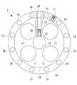
関節駒4は、図3に示されるように、円板状の本体部7と、該本体部7の中央に軸線に沿って、一方向に延びる第1の支柱部8とを備えている。本体部7には、厚さ方向に貫通する4つの貫通孔9が設けられており、中央の第1の支柱部8と外周の円環状部分10とを4本のスポーク11によって連結した形態を有している。これにより、円環状部分10、第1の支柱部8および隣接する2本のスポーク11によって囲まれる空間として貫通孔9が形成されている。 As shown in FIG. 3, the joint piece 4 includes a disk-shaped
最先端の関節駒4以外の関節駒4には、図4に示されるように、本体部7を挟んで第1の支柱部8とは逆方向に軸線に沿って延びる第2の支柱部12が設けられている。第1の支柱部8の先端には隣接する関節駒4に設けられている第2の支柱部12の先端と揺動可能に連結する連結部13が設けられている。図2〜図4に示す例では、隣接する関節駒4は交互に非平行な揺動軸線S回りに揺動するように連結部13が構成されている。 As shown in FIG. 4, in the joint pieces 4 other than the most advanced joint piece 4, the
ガイドプレート5は、円板状の第1のプレート部14と、該第1のプレート部14の外周に周方向に角度調節可能に取り付けられた円環状の第2のプレート部15とを備えている。
第1のプレート部14は、図3および図4に示されるように、各関節駒4の第1の支柱部8を嵌合させる嵌合孔16を中央に備えるとともに、その外側に板厚方向に貫通する4個の貫通孔(開口部)17を備えている。貫通孔17には、図7に示されるように、軟性の処置具、配管あるいは軟性内視鏡のような内蔵物18を貫通させることができるようになっている。The
As shown in FIG. 3 and FIG. 4, the
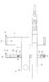
また、第2のプレート部15は、周方向に間隔をあけて板厚方向に貫通する複数の貫通孔(案内通路)19を備えている。これらの貫通孔19は、例えば、図5に示されるように、第2のプレート部15の軸線に平行な方向に対して周方向一方向に傾斜して設けられている。これらの貫通孔19の口径は、後述する張力伝達部材6を構成しているシース26の外形よりも大きく、シース26を貫通させることができる寸法に形成されている。また、各貫通孔19の両端のエッジには、面取り加工またはR面加工が施されている。 Further, the
また、第1のプレート部14および第2のプレート部15には、図6に示されるように、径方向に貫通するネジ孔20,21が設けられている。各ネジ孔20,21には押しネジ22,23が締結されるようになっている。第1のプレート部14のネジ孔20に押しネジ22を締結することにより、嵌合孔16に嵌合している第1の支柱部8の外表面に押しネジ22を押し付けて、第1のプレート部14を第1の支柱部8に固定することができるようになっている。また、第2のプレート部15のネジ孔21に押しネジ23を締結することにより、第1のプレート部14の外表面に押しネジ23を押し付けて、第2のプレート部15を第1のプレート部14に固定することができるようになっている。 Further, as shown in FIG. 6, the
図6に示す例では、第2のプレート部15には、ネジ孔21の他に径方向に貫通する貫通孔24が設けられている。この貫通孔24は、第1のプレート部14に対する第2のプレート部15の所定の角度位置で、第1のプレート部14に設けられているネジ孔20に一致する位置に形成されている。これにより、貫通孔24がネジ孔20に一致するように第1のプレート部14と第2のプレート部15との相対角度位置を調節した状態で、ガイドプレート5全体を第1の支柱部8に対して位置合わせし、ネジ孔20に押しネジ22を締結することにより、第1のプレート部14を第1の支柱部8に固定することができるようになっている。 In the example shown in FIG. 6, the
張力伝達部材6は、図5に示されるように、金属製のワイヤ25と、該ワイヤ25を被覆するチューブ状のシース26とを備えている。張力伝達部材6は、各関節駒4において、第1の支柱部8の軸線を含み、揺動軸線Sに直交する平面内において、第1の支柱部8を挟んで反対側の位置の本体部7近傍に1本ずつ、合計2本固定されている。いずれかの張力伝達部材6に張力Fを付与すると、図3に示されるように、張力伝達部材6が固定されている関節駒4およびガイドプレート5が一体的に揺動軸線S回りに揺動させられるようになっている。 As shown in FIG. 5, the
シース26は、例えば、4フッ化エチレンのような摩擦係数の低い材質からなり、あるいは、そのような材質からなるコーティングが外表面に施されている。
関節駒4の本体部7に一端が固定された張力伝達部材6は、図2に示されるように、該本体部7よりも基端側に配されている1以上のガイドプレート5の貫通孔19および本体部7の貫通孔9を通過させられて軟性医療器具1の基端側まで導かれている。The
As shown in FIG. 2, the
特に、本実施形態においては、間隔をあけて配置されている複数のガイドプレート5の貫通孔19を通過させられる際に、隣接するガイドプレート5の貫通孔19とは異なる周方向位置に配置されている貫通孔19を通過させられることにより、関節駒4の長手軸回りに延びる螺旋状の湾曲経路に沿ってルーティングされるようになっている。 In particular, in the present embodiment, when the through
このように構成された本実施形態に係る軟性医療器具1および湾曲機構2の作用について以下に説明する。
本実施形態に係る湾曲機構2によれば、基端側に導かれたいずれかの張力伝達部材6に張力を付与することにより、図3に示されるように、その張力が付与された張力伝達部材6の一端が固定されている関節駒4が揺動軸線S回りに揺動させられる。これにより、湾曲機構2の先端部の位置および姿勢を変化させることができる。The operation of the flexible
According to the
この場合において、本実施形態に係る湾曲機構2においては、張力伝達部材6が螺旋状の湾曲経路に沿ってルーティングされているので、いずれかの関節駒4が揺動させられても、他の関節駒4を駆動する張力伝達部材6はその湾曲の形態を変化させるだけで、張力を変化させずに済むので、他の関節駒4の揺動角度を変動させてしまうことを防止することができるという利点がある。 In this case, in the
張力伝達部材6のルーティングは以下の手順で行う。すなわち、関節駒4の第1の支柱部8を第1のプレート部14の嵌合孔16に嵌合し、押しネジ22による固定を行っていない状態で、第2のプレート部15の貫通孔19に張力伝達部材6を貫通させる。そして、ガイドプレート5の長手軸方向位置および第1のプレート部14の貫通孔17の周方向位置および第2のプレート部15の貫通孔19の周方向位置を調整する。調整に際しては、全ての張力伝達部材6が無理なく移動できる位置に調節する。 The
この状態で、第1のプレート部14のネジ孔20と第2のプレート部15の貫通孔24とを一致させて、工具を挿入し、押しネジ22をネジ孔20に締結して第1のプレート部14を第1の支柱部8に固定する。これにより、第1のプレート部14の貫通孔17の周方向位置および第2のプレート部15の貫通孔24の長手軸方向位置が固定される。次いで、第2のプレート部15のネジ孔21に押しネジ23を締結し、第2のプレート部15を第1のプレート部14に固定する。上記作業を全てのガイドプレート5に対して行うことにより、張力伝達部材6のルーティングが完了する。 In this state, the
このように、本実施形態に係る湾曲機構2によれば、張力伝達部材6の湾曲経路に沿うルーティングがガイドプレート5の第2のプレート部15に設けられた貫通孔19に張力伝達部材6を貫通させることにより行われており、第2のプレート部15を第1のプレート部14に対して周方向に回転させて、貫通孔19の周方向位置を調節することができる。さらに、関節駒4の第1の支柱部8に対して第1のプレート部14を長手軸方向に移動させて、貫通孔19の長手軸方向位置も調節することができる。
これにより、張力伝達部材6が無理なくルーティングできる位置に貫通孔19を配置することができるという利点がある。Thus, according to the
Thereby, there exists an advantage that the through-
また、本実施形態においては、ガイドプレート5を2つに分け、第1のプレート部14と第2のプレート部15とを相対回転可能に設けているので、第1のプレート部14に設けられた貫通孔17の周方向位置と第2のプレート部15に設けられた貫通孔19の周方向位置とを独立して調節することができる。すなわち、張力伝達部材6が無理なくルーティングできる位置に第2のプレート部15の貫通孔19を配置し、かつ、処置具等の内蔵物18を長手軸に沿って真っ直ぐに貫通できる位置に第1のプレート部14の貫通孔17を配置することができるという利点がある In the present embodiment, the
また、第2のプレート部15の貫通孔19が、周方向に傾斜して形成されているので、貫通孔19を貫通する張力伝達部材6が滑らかな湾曲経路を形成することができる。そして、貫通孔19のエッジに面取り加工等が施されているので、貫通孔19内でシース26が移動する際にエッジに引っかかることが防止される。さらに、シース26が4フッ化エチレン等の低摩擦材料によって構成されているので、貫通孔19内でシース26を円滑に移動させることができる。 Moreover, since the through-
また、本実施形態に係る軟性医療器具1によれば、上述した湾曲機構2を軟性のアウターシース3によって被覆しているので、体内に挿入しても湾曲機構2と組織との接触がアウターシース3によって遮断され、湾曲機構2および組織の双方が保護される。そして、湾曲機構2が、いずれかの張力伝達部材6の操作により目的とする関節駒4のみを揺動させるので、湾曲機構2の先端に配置した処置具等の内蔵物18の先端部等が意図しない方向に動いてしまうことを防止して、操作性を向上することができるという利点がある。 Further, according to the flexible
なお、本実施形態においては、関節駒4として中央に第1の支柱部8を有するものを採用し、ガイドプレート5として第1の支柱部8を嵌合させる嵌合孔16を有するものを例示したが、これに代えて、図8および図9に示されるように、円筒状の関節駒27を採用し、該関節駒27の内周面に長手方向位置および周方向位置を調節可能なガイドプレート28を配置してもよい。 In the present embodiment, the joint piece 4 having the
ガイドプレート28としては、図9に示されるような関節駒27の内周面に設けた幅広の周溝29内に収容されて、該周溝29の幅寸法の範囲で長手軸方向に移動可能に配置された円環状の第2のプレート部30と、該第2のプレート部30の内周面に周方向に移動可能に設けられた第1のプレート部31とを有するものを例示することができる。第1のプレート部31は内蔵物18を貫通させる貫通孔17を有し、第2のプレート部30は張力伝達部材(図示略)6を貫通可能な貫通孔19を有する点においては上記実施形態と同様である。
図に示す例では、ガイドプレート28の長手軸方向位置は、3段階で調節することができるように、長手軸方向に間隔をあけて3カ所にネジ孔32および貫通孔33が形成されている。関節駒27のネジ孔32に押しネジ34を締結することにより、第2のプレート部30の外表面に押しネジ34を押し付けて、ガイドプレート28を関節駒27に固定することができるようになっている。The
In the example shown in the figure, screw holes 32 and through
本実施形態の説明において、図2では3個の関節駒4を図示したが、関節駒4の数はこれに限定されない。また、ガイドプレート5に設けた貫通孔17,19の数や大きさも図面に例示されたものに限定されるものではない。また、隣接する関節駒4が、相互に直交する揺動平面に沿って揺動することとしたが、これに限定されるものではなく、揺動平面の交差する角度は90°以外でもよいし、同一揺動平面内で揺動する関節駒4を隣接させてもよい。 In the description of the present embodiment, three joint pieces 4 are illustrated in FIG. 2, but the number of joint pieces 4 is not limited to this. Further, the number and size of the through
また、上記実施形態においては、張力伝達部材6を螺旋状にルーティングすることとしたが、これに代えて、関節駒4の長手軸回りに湾曲する任意の湾曲形態を採用してもよい。 Moreover, in the said embodiment, although the
1 軟性医療器具
2 湾曲機構
3 アウターシース
4 関節駒(湾曲関節部材)
5 ガイドプレート(ガイド部材)
6 張力伝達部材
9 貫通孔
14 第1のプレート部
15 第2のプレート部
17 貫通孔(開口部)
19 貫通孔(案内通路)
25 ワイヤ
26 シースDESCRIPTION OF
5 Guide plate (guide member)
6
19 Through hole (guide passage)
25
Claims (11)
Translated fromJapanese各該湾曲関節部材を独立して駆動するための張力を伝達する複数の長尺の張力伝達部材と、
該張力伝達部材をその長手方向に移動可能に支持するとともに、前記長手軸回りに延びる湾曲経路に沿って案内する案内通路を有する1以上のガイド部材とを備える湾曲機構。A plurality of curved joint members connected in series along the longitudinal axis;
A plurality of elongated tension transmitting members that transmit tension for independently driving the curved joint members;
A bending mechanism comprising: one or more guide members that support the tension transmission member so as to be movable in the longitudinal direction and have a guide passage that guides the tension transmission member along a curved path extending around the longitudinal axis.
前記案内通路が、前記ガイドプレートを板厚方向に貫通する貫通孔または貫通溝である請求項1に記載の湾曲機構。The guide member is a flat guide plate disposed to intersect the longitudinal axis;
The bending mechanism according to claim 1, wherein the guide passage is a through hole or a through groove that penetrates the guide plate in a plate thickness direction.
前記案内通路が、前記第1のプレート部に設けられ、
前記開口部が、前記第2のプレート部に設けられている請求項3に記載の湾曲機構。The guide plate is provided with a first plate portion that is adjustable with respect to any one of the curved joint members so that the angle around the longitudinal axis can be adjusted, and a relative angle around the longitudinal axis with respect to the first plate portion. A second plate portion that is adjustably mounted;
The guide passage is provided in the first plate portion;
The bending mechanism according to claim 3, wherein the opening is provided in the second plate portion.
該湾曲機構の外周を被覆する可撓性を有する筒状のアウターシースとを備える軟性医療器具。A bending mechanism according to any one of claims 1 to 10,
A flexible medical instrument comprising a flexible cylindrical outer sheath that covers the outer periphery of the bending mechanism.
Applications Claiming Priority (1)
| Application Number | Priority Date | Filing Date | Title |
|---|---|---|---|
| PCT/JP2014/077954WO2016063348A1 (en) | 2014-10-21 | 2014-10-21 | Curving mechanism and flexible medical equipment |
Publications (1)
| Publication Number | Publication Date |
|---|---|
| JPWO2016063348A1true JPWO2016063348A1 (en) | 2017-09-28 |
Family
ID=55760422
Family Applications (1)
| Application Number | Title | Priority Date | Filing Date |
|---|---|---|---|
| JP2016554977ACeasedJPWO2016063348A1 (en) | 2014-10-21 | 2014-10-21 | Bending mechanism and flexible medical device |
Country Status (3)
| Country | Link |
|---|---|
| US (1) | US11130244B2 (en) |
| JP (1) | JPWO2016063348A1 (en) |
| WO (1) | WO2016063348A1 (en) |
Families Citing this family (14)
| Publication number | Priority date | Publication date | Assignee | Title |
|---|---|---|---|---|
| US11104011B2 (en)* | 2016-11-10 | 2021-08-31 | Robert Chisena | Mechanical robot arm assembly |
| CN107042518B (en)* | 2017-04-18 | 2019-05-14 | 哈尔滨工业大学 | A kind of bionical frog software flippers with torsion open and close movement form |
| WO2018216109A1 (en)* | 2017-05-23 | 2018-11-29 | オリンパス株式会社 | Flexible manipulator |
| EP3668690A1 (en)* | 2017-08-15 | 2020-06-24 | University Of Dundee | Soft actuator |
| CN107538431B (en) | 2017-09-20 | 2019-11-05 | 京东方科技集团股份有限公司 | A kind of electric tool |
| US11458641B2 (en)* | 2018-05-23 | 2022-10-04 | General Electric Company | Robotic arm assembly construction |
| CN110065058B (en)* | 2019-05-20 | 2020-12-08 | 浙江大学 | An elephant trunk-like flexible robotic arm |
| CN112370272A (en)* | 2019-05-27 | 2021-02-19 | 蔡桂平 | A flexible skeleton and robot for joint rehabilitation training |
| CN112971987A (en)* | 2019-12-18 | 2021-06-18 | 新加坡国立大学 | Variable rigidity and flexible robot control device |
| CN113618778A (en)* | 2021-07-28 | 2021-11-09 | 孙建平 | Bionic mechanical arm |
| CN114770596B (en)* | 2022-04-28 | 2023-08-11 | 东南大学 | Medical behavior acquisition robot based on active vision and hearing and control method |
| CN115005993B (en)* | 2022-05-31 | 2023-09-22 | 四川省肿瘤医院 | Bending mechanism and surgical mechanical arm using same |
| CN115229843B (en)* | 2022-08-25 | 2024-11-08 | 同济大学 | Modularized bionic snake-shaped mechanical arm internal structure and wiring method thereof |
| NL2035502B1 (en) | 2023-07-28 | 2025-02-11 | Fortimedix Assets Ii B V | Bendable tube with path length compensation of steering wires |
Citations (8)
| Publication number | Priority date | Publication date | Assignee | Title |
|---|---|---|---|---|
| JPS62292385A (en)* | 1986-06-10 | 1987-12-19 | ロ−ド・コ−ポレ−シヨン | Body manipulator |
| JP2005271183A (en)* | 2004-03-26 | 2005-10-06 | Sharp Corp | Articulated drive |
| WO2007069667A1 (en)* | 2005-12-15 | 2007-06-21 | Tokyo Institute Of Technology | Elastic joint device |
| US20080257096A1 (en)* | 2005-04-01 | 2008-10-23 | Zhenqi Zhu | Flexible Parallel Manipulator For Nano-, Meso- or Macro-Positioning With Multi-Degrees of Freedom |
| JP2008272204A (en)* | 2007-04-27 | 2008-11-13 | Naohisa Yahagi | Endoscopic treatment tool |
| US20090099420A1 (en)* | 2007-10-11 | 2009-04-16 | Neoguide Systems, Inc. | System for managing bowden cables in articulating instruments |
| JP2010223724A (en)* | 2009-03-23 | 2010-10-07 | Olympus Corp | Tension detection mechanism and manipulator using the same |
| JP2012096337A (en)* | 2010-11-05 | 2012-05-24 | Ryutai Servo:Kk | Parallel mechanism using a plurality of elastic wires having rigidity |
Family Cites Families (9)
| Publication number | Priority date | Publication date | Assignee | Title |
|---|---|---|---|---|
| US8205522B2 (en)* | 2001-06-13 | 2012-06-26 | Oliver Crispin Robotics Limited | Link assembly with defined boundaries for a snake like robot arm |
| US8375808B2 (en)* | 2005-12-30 | 2013-02-19 | Intuitive Surgical Operations, Inc. | Force sensing for surgical instruments |
| GB0600170D0 (en)* | 2006-01-06 | 2006-02-15 | Oliver Crispin Robotics Ltd | Improvements in and relating to robotic arms |
| WO2008154408A1 (en)* | 2007-06-06 | 2008-12-18 | Tobey Wayland E | Modular hybrid snake arm |
| GB0712205D0 (en)* | 2007-06-23 | 2007-08-01 | Oliver Crispin Robotics Ltd | Improvements in and relating to robotoc arms |
| JP2009119064A (en) | 2007-11-15 | 2009-06-04 | Olympus Corp | Cover type endoscope, endoscope for cover, and endoscope cover |
| US9713873B2 (en)* | 2012-05-12 | 2017-07-25 | Massachusetts Institute Of Technology | Continuum style manipulator actuated with phase change media |
| CN103417298B (en)* | 2012-05-25 | 2017-10-10 | 三星电子株式会社 | Arm unit and the robot with the arm unit |
| CN103085083B (en)* | 2013-01-07 | 2015-06-24 | 汪雯 | Flexible continuous body mechanical structure capable of bending and stretching |
- 2014
- 2014-10-21JPJP2016554977Apatent/JPWO2016063348A1/ennot_activeCeased
- 2014-10-21WOPCT/JP2014/077954patent/WO2016063348A1/enactiveApplication Filing
- 2017
- 2017-04-07USUS15/481,616patent/US11130244B2/enactiveActive
Patent Citations (8)
| Publication number | Priority date | Publication date | Assignee | Title |
|---|---|---|---|---|
| JPS62292385A (en)* | 1986-06-10 | 1987-12-19 | ロ−ド・コ−ポレ−シヨン | Body manipulator |
| JP2005271183A (en)* | 2004-03-26 | 2005-10-06 | Sharp Corp | Articulated drive |
| US20080257096A1 (en)* | 2005-04-01 | 2008-10-23 | Zhenqi Zhu | Flexible Parallel Manipulator For Nano-, Meso- or Macro-Positioning With Multi-Degrees of Freedom |
| WO2007069667A1 (en)* | 2005-12-15 | 2007-06-21 | Tokyo Institute Of Technology | Elastic joint device |
| JP2008272204A (en)* | 2007-04-27 | 2008-11-13 | Naohisa Yahagi | Endoscopic treatment tool |
| US20090099420A1 (en)* | 2007-10-11 | 2009-04-16 | Neoguide Systems, Inc. | System for managing bowden cables in articulating instruments |
| JP2010223724A (en)* | 2009-03-23 | 2010-10-07 | Olympus Corp | Tension detection mechanism and manipulator using the same |
| JP2012096337A (en)* | 2010-11-05 | 2012-05-24 | Ryutai Servo:Kk | Parallel mechanism using a plurality of elastic wires having rigidity |
Also Published As
| Publication number | Publication date |
|---|---|
| US11130244B2 (en) | 2021-09-28 |
| US20170210015A1 (en) | 2017-07-27 |
| WO2016063348A1 (en) | 2016-04-28 |
Similar Documents
| Publication | Publication Date | Title |
|---|---|---|
| WO2016063348A1 (en) | Curving mechanism and flexible medical equipment | |
| US11350998B2 (en) | Medical instrument having translatable spool | |
| KR102046373B1 (en) | Laparoscopic surgery device having wire reducer | |
| US10856947B2 (en) | Grip force sensation feedback device and stylus-type force sensation feedback device | |
| US10792061B2 (en) | Motion amplifier for a steering mechanism of a steerable tool | |
| JP6129087B2 (en) | Joint mechanism, manipulator and manipulator system | |
| JP5253689B1 (en) | Insertion equipment | |
| CN102006816B (en) | An instrument for endoscopic applications, etc. | |
| US20190167368A1 (en) | Medical instrument | |
| WO2014156352A1 (en) | Outer sleeve tube and treatment tool | |
| KR102394198B1 (en) | Actuation element guide with twisting channels | |
| WO2016056417A1 (en) | Endoscope | |
| WO2015174304A1 (en) | Adapter for treatment instrument, endoscope, and endoscope system | |
| US20200155257A1 (en) | Treatment tool | |
| JP6271098B1 (en) | Medical overtube | |
| JP6296869B2 (en) | Treatment instrument and surgical system | |
| US20160270871A1 (en) | Treatment device | |
| EP3207853A1 (en) | Endoscope | |
| WO2017010128A1 (en) | Drive force transmission mechanism for medical device | |
| JPWO2017175373A1 (en) | Flexible manipulator | |
| JP6588540B2 (en) | Bending mechanism and flexible medical device | |
| WO2020110282A1 (en) | Medical treatment tool | |
| JP2006061176A (en) | Bending device | |
| WO2021181494A1 (en) | Medical manipulator | |
| CN110381803A (en) | Flexible mechanism |
Legal Events
| Date | Code | Title | Description |
|---|---|---|---|
| A621 | Written request for application examination | Free format text:JAPANESE INTERMEDIATE CODE: A621 Effective date:20171005 | |
| A131 | Notification of reasons for refusal | Free format text:JAPANESE INTERMEDIATE CODE: A131 Effective date:20180703 | |
| A521 | Request for written amendment filed | Free format text:JAPANESE INTERMEDIATE CODE: A523 Effective date:20180823 | |
| A131 | Notification of reasons for refusal | Free format text:JAPANESE INTERMEDIATE CODE: A131 Effective date:20190205 | |
| A521 | Request for written amendment filed | Free format text:JAPANESE INTERMEDIATE CODE: A523 Effective date:20190305 | |
| A01 | Written decision to grant a patent or to grant a registration (utility model) | Free format text:JAPANESE INTERMEDIATE CODE: A01 Effective date:20190903 | |
| A045 | Written measure of dismissal of application [lapsed due to lack of payment] | Free format text:JAPANESE INTERMEDIATE CODE: A045 Effective date:20200128 |