JPWO2015177859A1 - Wireless power transmission control method and wireless power transmission system - Google Patents
Wireless power transmission control method and wireless power transmission systemDownload PDFInfo
- Publication number
- JPWO2015177859A1 JPWO2015177859A1JP2016520838AJP2016520838AJPWO2015177859A1JP WO2015177859 A1JPWO2015177859 A1JP WO2015177859A1JP 2016520838 AJP2016520838 AJP 2016520838AJP 2016520838 AJP2016520838 AJP 2016520838AJP WO2015177859 A1JPWO2015177859 A1JP WO2015177859A1
- Authority
- JP
- Japan
- Prior art keywords
- power
- power transmission
- receivers
- wireless
- receiver
- Prior art date
- Legal status (The legal status is an assumption and is not a legal conclusion. Google has not performed a legal analysis and makes no representation as to the accuracy of the status listed.)
- Granted
Links
Images


Classifications
- H—ELECTRICITY
- H02—GENERATION; CONVERSION OR DISTRIBUTION OF ELECTRIC POWER
- H02J—CIRCUIT ARRANGEMENTS OR SYSTEMS FOR SUPPLYING OR DISTRIBUTING ELECTRIC POWER; SYSTEMS FOR STORING ELECTRIC ENERGY
- H02J50/00—Circuit arrangements or systems for wireless supply or distribution of electric power
- H02J50/10—Circuit arrangements or systems for wireless supply or distribution of electric power using inductive coupling
- H02J50/12—Circuit arrangements or systems for wireless supply or distribution of electric power using inductive coupling of the resonant type
- H—ELECTRICITY
- H02—GENERATION; CONVERSION OR DISTRIBUTION OF ELECTRIC POWER
- H02J—CIRCUIT ARRANGEMENTS OR SYSTEMS FOR SUPPLYING OR DISTRIBUTING ELECTRIC POWER; SYSTEMS FOR STORING ELECTRIC ENERGY
- H02J50/00—Circuit arrangements or systems for wireless supply or distribution of electric power
- H02J50/40—Circuit arrangements or systems for wireless supply or distribution of electric power using two or more transmitting or receiving devices
- H—ELECTRICITY
- H02—GENERATION; CONVERSION OR DISTRIBUTION OF ELECTRIC POWER
- H02J—CIRCUIT ARRANGEMENTS OR SYSTEMS FOR SUPPLYING OR DISTRIBUTING ELECTRIC POWER; SYSTEMS FOR STORING ELECTRIC ENERGY
- H02J50/00—Circuit arrangements or systems for wireless supply or distribution of electric power
- H02J50/80—Circuit arrangements or systems for wireless supply or distribution of electric power involving the exchange of data, concerning supply or distribution of electric power, between transmitting devices and receiving devices
- H—ELECTRICITY
- H02—GENERATION; CONVERSION OR DISTRIBUTION OF ELECTRIC POWER
- H02J—CIRCUIT ARRANGEMENTS OR SYSTEMS FOR SUPPLYING OR DISTRIBUTING ELECTRIC POWER; SYSTEMS FOR STORING ELECTRIC ENERGY
- H02J50/00—Circuit arrangements or systems for wireless supply or distribution of electric power
- H02J50/90—Circuit arrangements or systems for wireless supply or distribution of electric power involving detection or optimisation of position, e.g. alignment
- H—ELECTRICITY
- H04—ELECTRIC COMMUNICATION TECHNIQUE
- H04B—TRANSMISSION
- H04B5/00—Near-field transmission systems, e.g. inductive or capacitive transmission systems
- H04B5/70—Near-field transmission systems, e.g. inductive or capacitive transmission systems specially adapted for specific purposes
- H04B5/79—Near-field transmission systems, e.g. inductive or capacitive transmission systems specially adapted for specific purposes for data transfer in combination with power transfer
Landscapes
- Engineering & Computer Science (AREA)
- Computer Networks & Wireless Communication (AREA)
- Power Engineering (AREA)
- Signal Processing (AREA)
- Charge And Discharge Circuits For Batteries Or The Like (AREA)
Abstract
Translated fromJapaneseDescription
Translated fromJapaneseこの出願で言及する実施例は、無線電力伝送制御方法および無線電力伝送システムに関する。 The embodiments mentioned in this application relate to a wireless power transmission control method and a wireless power transmission system.
近年、電源供給や充電を行うために、無線で電力を伝送する技術が注目されている。例えば、携帯端末やノートパソコンを始めとした様々な電子機器や家電機器、或いは、電力インフラ機器に対して、無線で電力伝送を行う無線電力伝送システムが研究・開発されている。 In recent years, in order to perform power supply and charging, a technique for transmitting power wirelessly has attracted attention. For example, wireless power transmission systems that wirelessly transmit power to various electronic devices such as mobile terminals and notebook computers, home appliances, and power infrastructure devices are being researched and developed.
ところで、無線電力伝送(ワイヤレス電力伝送:Wireless Power Transfer)を利用する場合、電力を送る側の送電器と、送電器から送られた電力を受け取る側の受電器がそれぞれ異なるメーカの製品であっても支障なく使用するために標準化を行うのが好ましい。 By the way, when using wireless power transfer (Wireless Power Transfer), the transmitter on the side that sends power and the receiver on the side that receives the power sent from the transmitter are products of different manufacturers. However, it is preferable to perform standardization so that it can be used without any problem.
従来、無線による電力伝送技術としては、一般的に、電磁誘導を利用した技術や電波を利用した技術が知られている。 Conventionally, as a wireless power transmission technique, a technique using electromagnetic induction and a technique using radio waves are generally known.
そして、近年、送電器と受電器の距離をある程度離しつつ、複数の受電器に対する電力伝送および受電器の三次元的な様々な姿勢に対する電力伝送が可能なものとして、強結合系の共振を用いたワイヤレス送電技術が注目されている。 In recent years, the resonance of a strongly coupled system has been used to enable power transmission to a plurality of power receivers and three-dimensional various postures of the power receivers while maintaining a certain distance between the power transmitter and the power receiver. Wireless power transmission technology that has been attracting attention.
この強結合系の共振を用いたワイヤレス送電としては、例えば、磁界共鳴(磁界共振)や電界共鳴(電界共振)を利用した無線電力伝送技術が知られている。 As wireless power transmission using the resonance of the strong coupling system, for example, a wireless power transmission technique using magnetic field resonance (magnetic field resonance) or electric field resonance (electric field resonance) is known.
従来、無線電力伝送技術としては、様々な提案がなされている。 Conventionally, various proposals have been made for wireless power transmission technology.
前述したように、従来、電源供給や充電を行うために無線で電力を伝送する無線電力伝送技術が注目されている。この無線電力伝送技術を適用した無線電力伝送システムは、通常、複数の受電器に対して電力を伝送するが、各受電器が要望する電力、或いは、送電器に対する各受電器の位置関係等に基づいた電力伝送制御が求められている。 As described above, conventionally, wireless power transmission technology that wirelessly transmits power for power supply and charging has attracted attention. A wireless power transmission system to which this wireless power transmission technology is applied normally transmits power to a plurality of power receivers. However, the power requested by each power receiver or the positional relationship of each power receiver with respect to the power transmitter, etc. There is a need for power transmission control based on this.
この送電器から複数の受電器への電力伝送としては、受電器ごとに電力伝送を行う時分割電力伝送、並びに、複数の受電器に対して同時に電力伝送を行う同時電力伝送がある。しかしながら、複数の受電器を含む無線電力伝送システムにおいて、それぞれの受電器に対して評価指標を設定し、その評価指標に基づいて無線電力伝送を行うことは行われておらず、各受電器に対して適切な無線電力伝送を行うことが困難であった。 As power transmission from this power transmitter to a plurality of power receivers, there are time-division power transmission that performs power transmission for each power receiver and simultaneous power transmission that performs power transmission to a plurality of power receivers simultaneously. However, in a wireless power transmission system including a plurality of power receivers, an evaluation index is set for each power receiver, and wireless power transmission is not performed based on the evaluation index. However, it has been difficult to perform appropriate wireless power transmission.
一実施形態によれば、少なくとも1つの送電器、および、少なくとも2つの受電器を含み、前記送電器からの電力を、磁界共鳴または電界共鳴を利用して無線により、それぞれの前記受電器に伝送する無線電力伝送制御方法が提供される。 According to one embodiment, including at least one power transmitter and at least two power receivers, the power from the power transmitter is transmitted to each of the power receivers wirelessly using magnetic field resonance or electric field resonance. A wireless power transmission control method is provided.
前記無線電力伝送制御方法は、複数の前記受電器に対して、同時に電力を伝送する同時電力伝送モードと、前記受電器に対して、時分割的に切り替えて順番に電力を伝送する時分割電力伝送モードと、を有する。 The wireless power transmission control method includes a simultaneous power transmission mode in which power is simultaneously transmitted to a plurality of the power receivers, and time-division power in which power is sequentially transmitted to the power receivers in a time-sharing manner. A transmission mode.
前記無線電力伝送制御方法は、それぞれの前記受電器に評価指標を設定し、前記評価指標に基づいて、前記同時電力伝送モードおよび前記時分割電力伝送モードを切り替えて無線電力伝送を行う。 In the wireless power transmission control method, an evaluation index is set for each of the power receivers, and wireless power transmission is performed by switching between the simultaneous power transmission mode and the time division power transmission mode based on the evaluation index.
開示の無線電力伝送制御方法および無線電力伝送システムは、複数の受電器に対して時分割電力伝送および同時電力伝送を切り替えて適切な無線電力伝送を行うことができるという効果を奏する。 The disclosed wireless power transmission control method and wireless power transmission system have an effect that appropriate wireless power transmission can be performed by switching time-division power transmission and simultaneous power transmission to a plurality of power receivers.
まず、無線電力伝送制御方法および無線電力伝送システムの実施例を詳述する前に、電力伝送システムの例、並びに、複数の送電器および受電器を含む関連技術の無線電力伝送システムを、図1〜図11Cを参照して説明する。 First, before describing embodiments of the wireless power transmission control method and the wireless power transmission system in detail, an example of a power transmission system and a related-art wireless power transmission system including a plurality of power transmitters and power receivers will be described with reference to FIG. This will be described with reference to FIG.
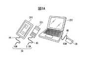
図1Aは、有線電力伝送(ワイヤー接続給電)システムの一例を模式的に示す図であり、図1Bは、無線電力伝送(ワイヤレス給電)システムの一例を模式的に示す図である。図1Aおよび図1Bにおいて、参照符号2A1〜2C1は、それぞれ受電器を示す。 FIG. 1A is a diagram schematically illustrating an example of a wired power transmission (wire connection feeding) system, and FIG. 1B is a diagram schematically illustrating an example of a wireless power transmission (wireless feeding) system. 1A and 1B, reference numerals 2A1 to 2C1 denote power receivers, respectively.
ここで、受電器2A1は、例えば、要望電力が10Wのタブレットコンピュータ(タブレット)を示し、受電器2B1は、例えば、要望電力が50Wのノートパソコンを示し、受電器2C1は、例えば、要望電力が2.5Wのスマートフォンを示す。なお、要望電力は、例えば、それぞれの受電器2A1〜2C1における充電池(二次電池)を充電するための電力に相当する。 Here, the power receiver 2A1 indicates, for example, a tablet computer (tablet) having a required power of 10 W, the power receiver 2B1 indicates, for example, a notebook computer having a required power of 50 W, and the power receiver 2C1 has a required power of, for example, A 2.5 W smartphone is shown. In addition, request | requirement electric power is corresponded to the electric power for charging the rechargeable battery (secondary battery) in each power receiving device 2A1-2C1, for example.
図1Aに示されるように、通常、タブレット2A1やスマートフォン2C1の二次電池を充電する場合、例えば、パソコン(Personal Computer)のUSB(Universal Serial Bus)端子(または、専用電源等)3Aに対して電源ケーブル4A,4Cを介して接続する。また、ノートパソコン2B1の二次電池を充電する場合、例えば、専用の電源装置(AC-DC Converter)3Bに対して電源ケーブル4Bを介して接続する。 As shown in FIG. 1A, when the secondary battery of the tablet 2A1 or the smartphone 2C1 is normally charged, for example, with respect to a USB (Universal Serial Bus) terminal (or a dedicated power source) 3A of a personal computer. Connection is made via
すなわち、図1Aに示されるように、携帯可能な受電器2A1〜2C1であっても、一般的に、電源ケーブル4A〜4Cを使用してUSB端子3Aや電源装置3Bからワイヤー接続給電(有線電力伝送)を行っている。 That is, as shown in FIG. 1A, even if the portable power receivers 2A1 to 2C1 are used, generally, the
ところで、近年、電磁誘導に代表される非接触給電技術の進歩により、例えば、シェーバーや電動歯ブラシ等でワイヤレス給電(無線電力伝送)が実用化されている。そこで、図1Bに示されるように、例えば、送電器1A1から、タブレット2A1,ノートパソコン2B1およびスマートフォン2C1に対して無線電力伝送することが考えられている。 By the way, in recent years, wireless power feeding (wireless power transmission) has been put into practical use, for example, with a shaver, an electric toothbrush, or the like, due to progress in non-contact power feeding technology represented by electromagnetic induction. Therefore, as shown in FIG. 1B, for example, it is considered to transmit wireless power from the power transmitter 1A1 to the tablet 2A1, the notebook computer 2B1, and the smartphone 2C1.
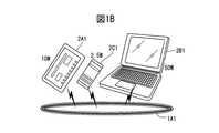
図2Aは、二次元無線電力伝送(二次元ワイヤレス給電)システムの一例を模式的に示す図であり、例えば、上述したシェーバーや電動歯ブラシ等と同様に、電磁誘導により無線電力伝送を行う様子を示している。 FIG. 2A is a diagram schematically illustrating an example of a two-dimensional wireless power transmission (two-dimensional wireless power feeding) system. For example, similarly to the above-described shaver, electric toothbrush, and the like, wireless power transmission is performed by electromagnetic induction. Show.
図2Aに示されるように、電磁誘導を利用して無線電力伝送を行う場合には、非接触給電であっても送電距離が短いために、送電器1A2にほぼ接触している受電器だけが給電可能である。 As shown in FIG. 2A, when wireless power transmission is performed using electromagnetic induction, only the power receiver that is substantially in contact with the
すなわち、送電器(受電台)1A2上に置かれた受電器(ノートパソコン)2B2に対しては給電することができても、受電台1A2から離れたノートパソコン2B3に対しては給電することは困難である。このように、図2Aに示す無線電力伝送システムは、受電台1A2上の自由な配置を可能とする二次元的なワイヤレス給電システムである。 In other words, even if power can be supplied to the power receiver (notebook computer) 2B2 placed on the power transmitter (power reception table) 1A2, power can be supplied to the notebook computer 2B3 that is remote from the power reception table 1A2. Have difficulty. As described above, the wireless power transmission system shown in FIG. 2A is a two-dimensional wireless power feeding system that allows free placement on the power receiving table 1A2.
図2Bは、三次元無線電力伝送(三次元ワイヤレス給電)システムの一例を模式的に示す図であり、例えば、磁界共鳴または電界共鳴を利用して無線電力伝送を行う様子を示している。図2Bに示されるように、磁界共鳴または電界共鳴を利用して無線電力伝送を行う場合には、送電器1A2から所定範囲内(図2Bにおける破線の内側)に存在する複数の受電器に対して給電することが可能である。 FIG. 2B is a diagram schematically illustrating an example of a three-dimensional wireless power transmission (three-dimensional wireless power feeding) system, and illustrates, for example, how wireless power transmission is performed using magnetic field resonance or electric field resonance. As shown in FIG. 2B, when wireless power transmission is performed using magnetic field resonance or electric field resonance, a plurality of power receivers existing within a predetermined range from the power transmitter 1A2 (inside the broken line in FIG. 2B) Can be supplied.
すなわち、送電器1A3から所定範囲内のタブレット2A2,2A3、ノートパソコン2B2,2B3およびスマートフォン2C2に対して無線電力伝送することが可能である。なお、図2Bでは、1つの送電器1A3のみ描かれているが、複数の送電器により、様々な角度および位置の複数の受電器に対して、磁界共鳴または電界共鳴を利用して無線電力伝送を行うようになっている。 That is, wireless power can be transmitted from the power transmitter 1A3 to the tablets 2A2 and 2A3, the notebook computers 2B2 and 2B3, and the smartphone 2C2 within a predetermined range. In FIG. 2B, only one power transmitter 1A3 is illustrated, but wireless power transmission is performed by using a plurality of power transmitters to a plurality of power receivers at various angles and positions using magnetic field resonance or electric field resonance. Is supposed to do.
このように、図2Bに示す無線電力伝送システムは、例えば、磁界共鳴を利用することにより、電磁誘導を利用したものに比べて遠方の空間においても高い送電効率を得ることができる三次元的なワイヤレス給電システムである。 As described above, the wireless power transmission system shown in FIG. 2B is, for example, a three-dimensional system that can obtain high power transmission efficiency even in a distant space as compared with the one using electromagnetic induction by using magnetic field resonance. It is a wireless power supply system.
図3は、無線電力伝送(三次元ワイヤレス給電)システムの一例を概略的に示すブロック図である。図3において、参照符号1は一次側(送電側:送電器)を示し、2は二次側(受電側:受電器)を示す。 FIG. 3 is a block diagram schematically showing an example of a wireless power transmission (three-dimensional wireless power feeding) system. In FIG. 3,
図3に示されるように、送電器1は、ワイヤレス送電部11、高周波電源部12、送電制御部13および通信回路部(第1通信回路部)14を含む。また、受電器2は、ワイヤレス受電部21、受電回路部(整流部)22、受電制御部23および通信回路部(第2通信回路部)24を含む。 As illustrated in FIG. 3, the
ワイヤレス送電部11は、第1コイル(電力供給コイル)11bおよび第2コイル(送電共振コイル)11aを含み、また、ワイヤレス受電部21は、第3コイル(受電共振コイル)21aおよび第4コイル(電力取出コイル)21bを含む。 The wireless
図3に示されるように、送電器1と受電器2は、送電共振コイル11aと受電共振コイル21aの間の磁界共鳴(電界共鳴)により、送電器1から受電器2へエネルギー(電力)の伝送を行う。なお、送電共振コイル11aから受電共振コイル21aへの電力伝送は、磁界共鳴だけでなく電界共鳴等も可能であるが、以下の説明では、主として磁界共鳴を例として説明する。 As shown in FIG. 3, the
送電器1と受電器2は、通信回路部14と通信回路部24により、通信(近距離通信)を行う。ここで、送電器1の送電共振コイル11aと受電器2の受電共振コイル21aによる電力の伝送距離(電力伝送範囲)は、送電器1の通信回路部14と受電器2の通信回路部24による通信距離(通信範囲)よりも短く設定される。 The
また、送電共振コイル11aおよび21aによる電力伝送は、通信回路部14および24による通信とは独立した方式(Out-band通信)になっている。具体的に、送電共振コイル11aおよび21aによる電力伝送は、例えば、6.78MHzの周波数帯域を使用し、通信回路部14および24による通信は、例えば、2.4GHzの周波数帯域を使用する。 Moreover, the power transmission by the power transmission resonance coils 11a and 21a is a method (Out-band communication) independent of the communication by the
この通信回路部14および24による通信としては、例えば、IEEE 802.11bに準拠するDSSS方式の無線LANやブルートゥース(Bluetooth(登録商標))を利用することができる。 As communication by the
なお、上述した無線電力伝送システムは、例えば、使用する周波数の波長程度の距離の近傍界(near field)において、送電器1の送電共振コイル11aと、受電器2の受電共振コイル21aによる磁界共鳴または電界共鳴を利用して電力の伝送を行う。従って、電力伝送範囲(送電圏)は、電力伝送に使用する周波数に従って変化する。 In the wireless power transmission system described above, for example, in the near field having a distance of about the wavelength of the frequency to be used, magnetic field resonance by the power
高周波電源部12は、電力供給コイル(第1コイル)11bに対して電力を供給し、電力供給コイル11bは、その電力供給コイル11bの至近に配設された送電共振コイル11aに対して電磁誘導を利用して電力を供給する。送電共振コイル11aは、受電共振コイル21aとの間に磁場共鳴を生じさせる共振周波数により、受電共振コイル21a(受電器2)に電力を伝送する。 The high frequency
受電共振コイル21aは、その受電共振コイル21aの至近に配設された電力取出コイル(第4コイル)21bに対して電磁誘導を利用して電力を供給する。電力取出コイル21bには受電回路部22が接続され、所定の電力が取り出される。なお、受電回路部22からの電力は、例えば、バッテリ部(負荷)25におけるバッテリの充電、或いは、受電器2の回路に対する電源出力等として利用される。 The power
ここで、送電器1の高周波電源部12は、送電制御部13により制御され、また、受電器2の受電回路部22は、受電制御部23により制御される。そして、送電制御部13および受電制御部23は、通信回路部14および24を介して接続され、送電器1から受電器2への電力伝送を好ましい状態で行うことができるように、様々な制御を行うようになっている。 Here, the high frequency
図4A〜図4Cは、図3の無線電力伝送システムにおける伝送コイルの変形例を説明するための図である。ここで、図4Aおよび図4Bは、3コイル構成の例を示し、図4Cは、2コイル構成の例を示す。 4A to 4C are diagrams for describing a modification example of the transmission coil in the wireless power transmission system of FIG. 3. Here, FIGS. 4A and 4B show an example of a three-coil configuration, and FIG. 4C shows an example of a two-coil configuration.
すなわち、図3に示す無線電力伝送システムでは、ワイヤレス送電部11が第1コイル11bおよび第2コイル11aを含み、ワイヤレス受電部21が第3コイル21aおよび第4コイルを含んでいる。 That is, in the wireless power transmission system shown in FIG. 3, the wireless
これに対して、図4Aの例では、ワイヤレス受電部21を1つのコイル(受電共振コイル:LC共振器)21aとし、図4Bの例では、ワイヤレス送電部11を1つのコイル(送電共振コイル:LC共振器)11aとしている。 On the other hand, in the example of FIG. 4A, the wireless
さらに、図4Cの例では、ワイヤレス受電部21を1つの受電共振コイル21aに設定すると共に、ワイヤレス送電部11を1つの送電共振コイル11aとしている。なお、図4A〜図4Cは、単なる例であり、様々に変形することができるのはいうまでもない。 Further, in the example of FIG. 4C, the wireless
図5A〜図5Dは、独立共振コイル(受電共振コイル21a)の例を示す回路図であり、図6A〜図6Dは、負荷または電源に接続された共振コイル(受電共振コイル21a)の例を示す回路図である。 5A to 5D are circuit diagrams showing examples of the independent resonance coil (power receiving
ここで、図5A〜図5Dは、図3および図4Bにおける受電共振コイル21aに対応し、図6A〜図6Dは、図4Aおよび図4Cにおける受電共振コイル21aに対応する。 5A to 5D correspond to the power
図5Aおよび図6Aに示す例は、受電共振コイル21aを、直列接続されたコイル(L)211,容量(C)212およびスイッチ213としたもので、通常時はスイッチ213をオフしておく。図5Bおよび図6Bに示す例は、受電共振コイル21aを、直列接続されたコイル(L)211および容量(C)212と、容量212に並列に接続されたスイッチ213としたもので、通常時はスイッチ213をオンしておく。 In the example shown in FIGS. 5A and 6A, the power
図5Cおよび図6Cに示す例は、図5Bおよび図6Bの受電共振コイル21aにおいて、容量212と並列に、直列接続されたスイッチ213および抵抗(R)214を設けたもので、通常時はスイッチ213をオンしておく。 The example shown in FIGS. 5C and 6C is such that a
図5Dおよび図6Dに示す例は、図5Bおよび図6Bの受電共振コイル21aにおいて、容量212と並列に、直列接続されたスイッチ213および他の容量(C')215を設けたもので、通常時はスイッチ213をオンしておく。 The example shown in FIGS. 5D and 6D is obtained by providing a
上述した各受電共振コイル21aにおいて、通常時に受電共振コイル21aが動作しないように、スイッチ213をオフまたはオンに設定するようになっている。これは、例えば、不使用の受電器2や故障した受電器2に対して電力が伝送されて発熱等が生じるのを避けるためである。 In each of the power
以上において、送電器1の送電共振コイル11aも図5A〜図5Dおよび図6A〜図6Dと同様にすることもできるが、送電器1の送電共振コイル11aとしては、通常時に動作するようにして、高周波電源部12の出力でオン/オフ制御してもよい。この場合、送電共振コイル11aは、図5Aおよび図6Aにおいて、スイッチ213を短絡したものになる。 In the above, the power
以上により、複数の受電器2が存在する場合、送電器1から送電を行う所定の受電器2の受電共振コイル21aのみを選択して動作可能な状態とすることにより、その選択された受電器2に対する電力の伝送(時分割電力伝送)を行うことが可能になる。 As described above, when there are a plurality of
図7A〜図7Cは、複数の送電器による磁界の制御例を説明するための図である。図7A〜図7Cにおいて、参照符号1Aおよび1Bは送電器を示し、2は受電器を示す。 FIG. 7A to FIG. 7C are diagrams for explaining an example of magnetic field control by a plurality of power transmitters. 7A to 7C,
図7Aに示されるように、送電器1Aの磁界共鳴に使用する送電用の送電共振コイル11aAと送電器1Bの磁界共鳴に使用する送電用の送電共振コイル11aBは、例えば、直交するように配設されている。 As shown in FIG. 7A, the power transmission resonance coil 11aA for power transmission used for the magnetic field resonance of the
また、受電器2の磁界共鳴に使用する受電用の受電共振コイル21aは、送電共振コイル11aAおよび11aBにより囲まれた個所で異なる角度(平行にならない角度)に配置されている。 In addition, the power
ここで、送電共振コイル(LC共振器)11aAおよび11aBは、1つの送電器に設けることも可能である。すなわち、1つの送電器1が複数のワイヤレス送電部11を含んでいてもよい。 Here, the power transmission resonance coils (LC resonators) 11aA and 11aB can be provided in one power transmission device. That is, one
図7Bは、送電共振コイル11aAおよび11aBが同じ位相の磁界を出力している様子を示し、図7Cは、送電共振コイル11aAおよび11aBが逆の位相の磁界を出力している様子を示す。 FIG. 7B shows a state in which the power transmission resonance coils 11aA and 11aB output magnetic fields having the same phase, and FIG. 7C shows a state in which the power transmission resonance coils 11aA and 11aB output magnetic fields having opposite phases.
例えば、2個の直交する送電共振コイル11aAおよび11aBが同相出力の場合と逆相出力の場合を比較すると、合成磁界は90°回転した関係となり、それぞれの受電器2(受電共振コイル21a)の向きに合わせた送電を行う。 For example, comparing the case where two orthogonal power transmission resonance coils 11aA and 11aB have the same phase output and the opposite phase output, the combined magnetic field is rotated by 90 °, and each power receiver 2 (power
このように、複数の送電器1A,1Bにより、任意の位置および姿勢(角度)の受電器2に対して電力を伝送する場合、送電器1A,1Bの送電共振コイル11aA,11aBに発生させる磁界は様々に変化することが分かる。 As described above, when power is transmitted to the
上述した無線電力伝送システムは、複数の送電器と、少なくとも1つの受電器とを含み、受電器の位置(X,Y,Z)および姿勢(θX,θY,θZ)に応じて、その複数の送電器間の出力(強度および位相)を調整する。The wireless power transmission system described above includes a plurality of power transmitters and at least one power receiver, and depends on the position (X, Y, Z) and posture (θX , θY , θZ ) of the power receiver, Adjust the output (intensity and phase) between the transmitters.
なお、三次元空間に関しても、例えば、実際の三次元空間における3個以上の送電器を用いて、それぞれの出力位相差および出力強度比を調整することで、三次元空間上の任意の方向に磁界(電界)の向きを調整することが可能になることが理解されるであろう。 As for the three-dimensional space, for example, by using three or more power transmitters in the actual three-dimensional space, and adjusting the output phase difference and the output intensity ratio, the direction can be adjusted in any direction on the three-dimensional space. It will be appreciated that the orientation of the magnetic field (electric field) can be adjusted.
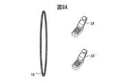
図8A〜図8Cは、複数の受電器に対する無線電力伝送を説明するための図である。なお、図8A〜図8Cでは、説明を簡略化するために、1つの送電器1Aおよび2つの受電器(携帯電話)2A,2A’のみ示しているが、送電器の数および受電器の数や種類等は様々に変化し得るのはいうまでもない。すなわち、図8Aに示されるように、1つの送電器1Aにより、2つの受電器2A,2A’に対するワイヤレス給電を行う場合を想定する。 8A to 8C are diagrams for explaining wireless power transmission to a plurality of power receivers. 8A to 8C, only one
まず、時分割電力伝送によりワイヤレス給電を行うときは、図8Bの左側図に示されるように、一方の受電器2Aだけに給電した後、図8Bの右側図に示されるように、他方の受電器2Aだけに給電する。なお、受電器の数がさらに多い場合も同様であり、時分割的に給電する受電器を順番に切り替えてワイヤレス給電を行う。 First, when performing wireless power feeding by time-division power transmission, as shown in the left side view of FIG. 8B, power is supplied only to one
すなわち、時分割電力伝送は、複数の受電器がある場合、給電する対象となる受電器を順次選択することにより、ある瞬間には常に送電器に対して1つの受電器が対応することになる。このときの制御は、例えば、送電器と受電器が1対1の場合と同様とすることができる。ただし、時分割した結果、給電(満充電)に要する時間は、受電器の数だけの時間となるため、受電器が2台であれば1台のときの2倍の時間を要することになる。 In other words, when there are a plurality of power receivers, the time division power transmission always selects one power receiver to be supplied, so that one power receiver always corresponds to the power transmitter at a certain moment. . The control at this time can be the same as the case where the power transmitter and the power receiver are one-to-one, for example. However, as a result of time division, the time required for power supply (full charge) is as long as the number of power receivers. Therefore, if there are two power receivers, it will take twice as long as one. .
次に、同時電力伝送によりワイヤレス給電を行うときは、図8Cに示されるように、1つの送電器1Aにより、2つの受電器2A,2A’の両方に給電する。なお、受電器の数がさらに多い場合も同様であり、それら複数の受電器に対して同時にワイヤレス給電を行う。 Next, when performing wireless power supply by simultaneous power transmission, as shown in FIG. 8C, power is supplied to both the two
この同時電力伝送は、例えば、2台の受電器がある場合にはその2台の受電器を同時に給電するため、給電に要する時間は、同時給電される受電器の数に関わらず、1台分でよいため、ユーザメリットを考えると望ましい給電方法(無線電力伝送制御方法)と言える。 In this simultaneous power transmission, for example, when there are two power receivers, power is supplied to the two power receivers at the same time. Therefore, the time required for power supply is one unit regardless of the number of power receivers that are simultaneously powered. Therefore, it can be said that it is a desirable power supply method (wireless power transmission control method) in consideration of user merits.
ただし、複数の受電器を同時給電(同時電力伝送)するには、受電器が1台のときとは異なる制御を行うことになる。また、複数の受電器に対して同時電力伝送を行う場合、送電上限や効率等の問題があるため、常に選択可能であるわけではない。なお、受電器の数が多数の場合、一部の複数の受電器に対して同時電力伝送を行い、他の受電器に対して時分割電力伝送を行うことも考えられる。 However, in order to supply power to a plurality of power receivers simultaneously (simultaneous power transmission), control different from that when one power receiver is used is performed. In addition, when performing simultaneous power transmission to a plurality of power receivers, there are problems such as the upper limit of power transmission and efficiency, so that selection is not always possible. When the number of power receivers is large, simultaneous power transmission may be performed for some of the plurality of power receivers, and time-division power transmission may be performed for other power receivers.
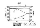
図9Aおよび図9Bは、複数の受電器に対する二次元の無線電力伝送制御方法の一例を説明するための図である。ここで、図9Aは、例えば、磁界共鳴を利用して、1つの送電器1Aにより、要望電力が異なる2つの受電器2A,2Bにワイヤレス給電する様子を示す。また、図9Bにおいて、参照符号LL0は全体送電効率を示し、LLAは携帯電話2Aの受電電力を示し、LLBはノートパソコン2Bの受電電力を示す。 9A and 9B are diagrams for describing an example of a two-dimensional wireless power transmission control method for a plurality of power receivers. Here, FIG. 9A shows a state in which, for example, magnetic power resonance is used to wirelessly feed two
なお、受電器2Aは、例えば、要望電力が5Wの携帯電話を示し、受電器2Bは、例えば、要望電力が50Wのノートパソコンを示す。また、説明を簡略化するために、携帯電話2AのLC共振器(ワイヤレス受電部)およびノートパソコン2BのLC共振器は、同じ仕様のものとする。 The
ところで、二次元無線電力伝送システムにおいて、複数の受電器への同時ワイヤレス給電を行う場合それぞれの受電器における受電電力量が異なるケースが多発すると考えられる。例えば、図9Aに示されるように、要望電力が5Wの携帯電話と要望電力が50Wのノートパソコン、或いは、同じ種類の受電器であっても、バッテリ残量によっては、要望電力が異なるケースも考えられる。 By the way, in the two-dimensional wireless power transmission system, when performing simultaneous wireless power feeding to a plurality of power receivers, it is considered that there are many cases in which the amount of received power in each power receiver is different. For example, as shown in FIG. 9A, there are cases in which the required power varies depending on the remaining battery level, even if the requested power is a 5 W mobile phone and the requested power is a 50 W notebook computer or the same type of power receiver. Conceivable.
これらの状況において、例えば、二次元無線電力伝送システムでは、送電器1A上に置かれる受電器2A,2Bの距離や姿勢の条件には大きな差がないと考えられるため、同じ仕様の受電コイルが搭載されている場合には、電力は等しく分配されることとなる。 In these situations, for example, in a two-dimensional wireless power transmission system, it is considered that there is no significant difference in the distance and posture conditions of the
そのため、図9Aに示されるように、要望電力が10倍異なる受電器2Aと2Bであっても、例えば、55Wの要望電力に相当する出力を送電器1Aから出力した場合、受電器2A,2B側では、それぞれ27.5Wずつの電力を受電する結果となる。 Therefore, as shown in FIG. 9A, even if the
すなわち、携帯電話2Aおよびノートパソコン2Bは、例えば、図5Aに示す受電共振コイル21aを有し、そのコイル211のインダクタンスおよび容量212のキャパシタンスは、同じ値である。 That is, the
具体的に、携帯電話2Aの受電共振コイルにおけるインダクタンスをLA,キャパシタンスをCAとし、ノートパソコン2Bの受電共振コイルにおけるインダクタンスをLB,キャパシタンスをCBとする。このとき、参照符号PP0で示されるように、そのままの状態(共振点ずらさない状態)では、L0C0=LACA=LBCBが成立する。Specifically, the inductance in the power receiving resonance coil of the
そのため、例えば、送電器1Aからの送電電力が68.75Wで送電効率が80%だと仮定すると、携帯電話2Aおよびノートパソコン2Bは、両方とも27.5Wの電力を受け取ることになる。 Therefore, for example, assuming that the transmission power from the
しかしながら、携帯電話2Aの要望電力は5Wで、ノートパソコン2Bの要望電力は50Wであるため、携帯電話2Aの受電共振コイルによる共振点をずらして受電効率を低下させるように制御する。 However, since the required power of the
例えば、図9Bの矢印MAに示されるように、携帯電話2Aの受電共振コイルにおける容量のキャパシタンスCAを、受電効率が最大となる受電共振コイルの共振点からずらすために、小さく(または、大きく)なるように制御する。For example, as indicated by the arrow MA in FIG. 9B, the capacitance CA of the capacitor in the power receiving
すなわち、図9Bの矢印MAのように、共振条件を意図的にずらす(キャパシタンスCAをずらす)ことでQ値を低下させ、携帯電話2Aの受電電力LLAは、共振点(P0)の27.5Wから次第に減少して、例えば、要望電力は5Wに設定することができる。That is, as shown by the arrow MA in FIG. 9B, intentionally shifting the resonance condition (shifting the capacitance CA) to lower the Q value by, received
このとき、携帯電話2Aが受電しなくなった電力は、そのほとんどがノートパソコン2Bの受電電力となる。すなわち、ノートパソコン2Bの受電電力LLBは、携帯電話2Aの受電電力LLAの低下に応じて上昇し、無線電力伝送システムにおける全体送電効率LL0は、ほとんど低下しないことが分かる。 At this time, most of the power that the
このように、共振条件を変えることで、具体的には、受電器2Aの共振用コンデンサ(容量)212の容量値(キャパシタンスCA)を変化させることで、結合が調整され、結果として、受電電力を所望の配分比に制御することが可能となる。In this way, by changing the resonance condition, specifically, the coupling is adjusted by changing the capacitance value (capacitance CA ) of the resonance capacitor (capacitance) 212 of the
ここで、重要なこととして、共振条件を可変した受電器2Aの効率は低下していても、システム全体の送受電効率はほぼ一定を保っており、受電器2Aに到達していた電力を減らした分、受電器2Bへの電力が増加する。その結果、受電器2A,2Bの一方だけの単体給電時と比べても、ほぼ同じ効率で全体(両方の受電器2A,2B)に送電しつつ受電電力を所望の比に分配(配分)できることがわかる。 Here, it is important that even if the efficiency of the
なお、各送電器には、それぞれ送電能力の上限が個別にあることが想定されるため、二次元無線電力伝送システムでは、同時給電が可能な場合と不可能な場合の判断は、例えば、以下のように、容易に行うことができる。 In addition, since it is assumed that each power transmitter has an upper limit of power transmission capacity individually, in the two-dimensional wireless power transmission system, the determination when simultaneous power feeding is possible and when it is impossible is, for example, As can be done easily.
すなわち、システム全体の送受電効率はほぼ一定であるため、単純に総受電電力/効率≦最大送電ならば同時給電を行い、総受電電力/効率>最大送電ならば時分割給電を行うという判断になる。 In other words, since the transmission / reception efficiency of the entire system is almost constant, it is determined that simultaneous power supply is performed if total received power / efficiency ≦ maximum transmission, and time-division power supply is performed if total received power / efficiency> maximum transmission. Become.
次に、三次元無線電力伝送システムについて説明する。図10A〜図11Cは、複数(2つ)の受電器に対する三次元の無線電力伝送制御方法の一例を説明するための図である。なお、図10A〜図11Cでは、説明を簡略化するために、1つの送電器1Aおよび2つの受電器2A,2Bを示しているが、複数の送電器および3つ以上の受電器であっても同様である。 Next, a three-dimensional wireless power transmission system will be described. 10A to 11C are diagrams for explaining an example of a three-dimensional wireless power transmission control method for a plurality (two) of power receivers. In FIG. 10A to FIG. 11C, one
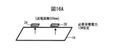
ここで、図10A〜図10Cは、送電器1Aから2つの受電器2A,2Bまでの距離が300mmの場合を示し、図11A〜図11Cは、送電器1Aから2つの受電器2A,2Bまでの距離が500mmの場合を示す。 Here, FIGS. 10A to 10C show the case where the distance from the
図10Bおよび図11Bにおいて、参照符号LAは、受電器2Aの受電効率、LBは、受電器2Bの受電効率、PMは、送電器1Aの出力可能な送電電力(最大送電出力)を示し、RPは、必要送電電力、そして、TPは、全体の受電効率(全体効率)を示す。 In FIG. 10B and FIG. 11B, the reference sign LA indicates the power reception efficiency of the
また、参照符号P0は、受電器2A,2Bの要望電力の比が1:1の送電(9W:9W)の場合を示し、P1は、受電器2A,2Bの要望電力の比が2:1の送電(12W:6W)の場合を示す。なお、図10Bおよび図11Bは、電力比1:1を『1.00』に規格化して示す図である。 Reference symbol P0 indicates a case of power transmission (9W: 9W) in which the ratio of the desired power of the
すなわち、2つの受電器2A,2Bへ伝送する電力を18Wとし、受電器2Aおよび2Bの要望電力が両方とも9Wの場合、並びに、受電器2Aの要望電力が12Wで受電器2Bの要望電力が6Wの場合を考える。なお、送電器1Aの最大送電出力は、例えば、送電器の仕様や電波法の規定等により50Wに制限されているものとする。 That is, when the power to be transmitted to the two
図10A〜図10Cを参照して、送電器1Aと2つの受電器2A,2Bまでの距離が300mmの場合(比較的に近い場合)を考察する。まず、同時給電を行う受電器2Aおよび2Bの要望電力が両方とも9Wの場合、すなわち、電力比1:1の送電(9W:9W)の場合、受電器2A,2Bの受電効率は、例えば、両方とも30.1%(全体効率(TP)が60.2%)であるとする。 With reference to FIGS. 10A to 10C, consider the case where the distance between the
このとき、図10BのP0および図10Cに示されるように、送電器1Aの送電出力を29.9Wとすることにより、受電器2Aおよび2Bは、それぞれ29.9×0.301≒9Wの電力を受電することができる。 At this time, as shown in P0 of FIG. 10B and FIG. 10C, by setting the power transmission output of the
次に、受電器2Aの要望電力が12Wで受電器2Bの要望電力が6Wの場合、すなわち、電力比2:1の送電(12W:6W)の場合、図9Aおよび図9Bを参照して説明したのと同様に、受電器2Bの受電共振コイルによる共振点をずらす。 Next, in the case where the required power of the
すなわち、受電器2Bの受電共振コイルによる共振点をずらし、受電器2Bの受電効率を低下(受電器2Aの受電効率を上昇)させるようにして電力配分比を制御し、受電器2Aおよび2Bに対して同時給電を行う。 That is, the resonance point by the power receiving resonance coil of the
具体的に、図10BのP1および図10Cに示されるように、受電器2Bの受電共振コイルの共振点をずらすことにより、受電器2Aの受電効率を39.5%とし、受電器2Bの受電効率を19.7%とする。このとき、全体効率(TP)は、59.2%となる。 Specifically, as shown in P1 of FIG. 10B and FIG. 10C, the power reception efficiency of the
そして、図10Cに示されるように、送電器1Aの送電出力を30.4Wとすることにより、受電器2Aは、30.4×0.395≒12Wの電力を受電することができ、受電器2Bは、30.4×0.197≒6Wの電力を受電することができる。 Then, as shown in FIG. 10C, by setting the power transmission output of the
ここで、送電器1Aと2つの受電器2A,2Bまでの距離が300mmの場合、送電器1Aの必要送電電力RPは、電力比1:1の送電(29.9W)および電力比2:1の送電(30.4W)の両方とも、最大送電出力の50Wよりも小さい。 Here, when the distance between the
さらに、全体効率TPは、電力比1:1の送電(60.2%)および電力比2:1の送電(59.2%)でほぼ一定である。従って、電器1Aと2つの受電器2A,2Bまでの距離が300mmの場合(比較的に近い場合)には、電力比1:1の送電および電力比2:1の送電の両方とも、同時給電により実現することができる。 Furthermore, the overall efficiency TP is substantially constant for power transmission with a power ratio of 1: 1 (60.2%) and power transmission with a power ratio of 2: 1 (59.2%). Therefore, when the distance between the
次に、図11A〜図11Cを参照して、送電器1Aと2つの受電器2A,2Bまでの距離が500mmの場合(比較的に遠い場合)を考察する。まず、同時給電を行う受電器2Aおよび2Bの要望電力が両方とも9Wの場合、すなわち、電力比1:1の送電(9W:9W)の場合、受電器2A,2Bの受電効率は、例えば、両方とも18.2%(全体効率(TP)が36.4%)であるとする。 Next, a case where the distance between the
このとき、図11BのP0および図11Cに示されるように、送電器1Aの送電出力を49.5Wとすることにより、受電器2Aおよび2Bは、それぞれ49.5×0.182≒9Wの電力を受電することができる。この場合、送電器1Aの必要送電電力RP(49.5W)は、最大送電出力の50Wよりも小さいため、受電器2Aおよび2Bに対する同時給電を行うことができる。 At this time, as shown in P0 of FIG. 11B and FIG. 11C, by setting the power transmission output of the
次に、受電器2Aの要望電力が12Wで受電器2Bの要望電力が6W(電力比2:1)の場合、上述したように、受電器2Bの受電共振コイルによる共振点をずらし、受電器2Bの受電効率を低下(受電器2Aの受電効率を上昇)させるように、電力配分比を制御する。 Next, when the desired power of the
具体的に、図11BのP1および図11Cに示されるように、受電器2Bの受電共振コイルの共振点をずらすことにより、受電器2Aの受電効率を21.2%とし、受電器2Bの受電効率を10.6%とする。このとき、全体効率(TP)は、31.8%となる。 Specifically, as shown in P1 of FIG. 11B and FIG. 11C, the power reception efficiency of the
しかしながら、受電器2Aの受電電力を12W(≒56.6×0.212)とするには、送電器1Aの必要送電電力RPは56.6Wとなり、最大送電出力の50Wよりも大きくなってしまう。従って、2つの受電器2Aおよび2Bに対して同時給電することは困難となる。 However, if the received power of the
なお、送電器1Aの送電出力が、例えば、送電器の仕様や電波法の規定等により50Wに制限されていない場合、送電器1Aは、56.6Wの必要送電電力RPを許容できる大きさまで増大させることが求められる。 When the power transmission output of the
また、同時給電を行うと、必要送電電力RPが56.6Wとなって最大送電出力(50W)を超過する場合には、受電器2A,2Bに対して、時分割的に切り替えて順番に電力を伝送する時分割電力伝送(時分割給電)を行うことになる。 In addition, when simultaneous power feeding is performed, if the required transmission power RP is 56.6 W and exceeds the maximum power transmission output (50 W), the power is sequentially switched to the
ここで、時分割給電において、送電器1Aにより受電器2Aまたは2Bの一方だけに電力伝送(給電)するときの受電効率を25%とする。このとき、送電器1Aの送電出力を48Wとして受電器2Aだけに給電することで、受電器2Aの受電電力を12W(=48×0.25)とすることができる。さらに、送電器1Aの送電出力を24Wとして受電器2Bだけに給電することで、受電器2Bの受電電力を6W(=24×0.25)とすることができる。 Here, in the time-sharing power supply, the power reception efficiency when power is transmitted (powered) to only one of the
従って、送電器1Aと2つの受電器2A,2Bまでの距離が500mmの場合(比較的に近い場合)、電力比1:1の送電は同時給電が好ましく、電力比2:1の送電は、時分割給電が好ましいもの(同時給電は不可)と考えられる。 Accordingly, when the distance between the
上述したように、例えば、送電器1Aと2つの受電器2A,2Bまでの距離が300mmの場合、電力分配の調整を行っても全体効率はほぼ一定であり、また、電力比1:1の送電が可能な受電電力ならば、電力比2:1(N:1)の同時給電も可能である。 As described above, for example, when the distance between the
これに対して、例えば、送電器1Aと2つの受電器2A,2Bまでの距離が500mmの場合、電力分配の調整を行うと全体効率が低下し、また、電力比N:1の送電を行うのが困難となり、或いは、送電器の最大送電出力の増加が求められることになる。このような同時給電が困難な場合には、時分割給電を行うことになる。 On the other hand, for example, when the distance between the
すなわち、複数の受電器を含む無線電力伝送システムにおいて、それぞれの受電器に対しては、同時給電を行うか、或いは、時分割給電を行うかを判断する評価指標の設定はなされておらず、各受電器に対して適切な給電(無線電力伝送)を行うことは困難である。 That is, in the wireless power transmission system including a plurality of power receivers, for each power receiver, there is no setting of an evaluation index for determining whether to perform simultaneous power feeding or time division power feeding, It is difficult to appropriately supply power (wireless power transmission) to each power receiver.
また、複数の受電器に対して同時給電が可能なケースと不可能なケースの判断基準が不明確である。さらに、例えば、シミュレーションやテスト送電を行うことも考えられるが、例えば、受電器の個数に従って増加する組み合わせは膨大であり、実際に適用するのは難しい。 Also, the criteria for determining whether or not simultaneous power feeding is possible for a plurality of power receivers are unclear. Furthermore, for example, it is conceivable to perform simulation or test power transmission. However, for example, the number of combinations that increase in accordance with the number of power receivers is enormous, and is difficult to apply in practice.
以下、無線電力伝送制御方法および無線電力伝送システムの実施例を、添付図面を参照して詳述する。ここで、本実施例は、少なくとも1つの送電器により複数の受電器に対する無線電力伝送を行う無線電力伝送システムに適用することができる。 Hereinafter, embodiments of a wireless power transmission control method and a wireless power transmission system will be described in detail with reference to the accompanying drawings. Here, the present embodiment can be applied to a wireless power transmission system that performs wireless power transmission to a plurality of power receivers using at least one power transmitter.
なお、以下の説明は、主として、磁界共鳴(磁界共振)を利用して1つの送電器で複数(2〜5個)の受電器に無線電力伝送を行う例を説明するが、本実施例は、図7A〜図7Cを参照して説明したように、2個以上の送電器により電力伝送を行ってもよい。さらに、本実施例は、磁界共鳴ではなく、電界共鳴(電界共振)を利用した無線電力伝送システムに対しても同様に適用することができる。 In the following description, an example in which wireless power transmission is performed to a plurality of (2 to 5) power receivers with one power transmitter using magnetic field resonance (magnetic field resonance) will be mainly described. As described with reference to FIGS. 7A to 7C, power transmission may be performed by two or more power transmitters. Furthermore, the present embodiment can be similarly applied to a wireless power transmission system using electric field resonance (electric field resonance) instead of magnetic field resonance.
本実施例の無線電力伝送制御方法および無線電力伝送システムにおいて、無線電力伝送(ワイヤレス給電)の評価指標としてkQ(kQ値)を適用する。ここで、k(k値)は、電磁界の結合の程度を示し、その値が大きいほど、結合の程度が大きいことを示す。また、Q(Q値)は、電磁界の損失の程度を示し、その値が大きいほど、損失の程度が小さいことを示す。 In the wireless power transmission control method and wireless power transmission system of this embodiment, kQ (kQ value) is applied as an evaluation index for wireless power transmission (wireless power feeding). Here, k (k value) indicates the degree of electromagnetic field coupling, and the larger the value, the greater the degree of coupling. Q (Q value) indicates the degree of electromagnetic field loss, and the larger the value, the smaller the loss.
すなわち、kQは、次の式(1)により表される。ここで、Qtは、送電器のQ値を示し、Qrは、受電器のQ値を示す。
また、kは、次の式(2)により表される。ここで、Mtrは、送電器と受電器の間の相互インダクタンスを示し、Ltは、送電器の自己インダクタンス、そして、Lrは、受電器の自己インダクタンスを示す。
さらに、Qは、次の式(3)により表される。ここで、ωは、角振動数を示し、Rtは、送電器の共振コイルの損失、そして、Rrは、受電器の共振コイルの損失を示す。
図12は、本実施形態の無線電力伝送制御方法における評価指標を説明するための図であり、1つの送電器と1つの受電器におけるkQ値(kとQの積)と理想効率の関係を示すものである。 FIG. 12 is a diagram for explaining an evaluation index in the wireless power transmission control method of the present embodiment, and shows the relationship between the kQ value (product of k and Q) and ideal efficiency in one power transmitter and one power receiver. It is shown.
図12において、横軸は、kQ値を示し、縦軸は、効率を示す。すなわち、本実施例では、例えば、図12のような特性の1つの送電器と1つの受電器におけるkQ値を、少なくとも1つの送電器と少なくとも2つ(複数)の受電器の電力伝送に適用する。 In FIG. 12, the horizontal axis indicates the kQ value, and the vertical axis indicates the efficiency. That is, in this embodiment, for example, the kQ value in one power transmitter and one power receiver having the characteristics as shown in FIG. 12 is applied to power transmission between at least one power transmitter and at least two (plurality) power receivers. To do.
本実施例の無線電力伝送制御方法および無線電力伝送(ワイヤレス給電)システムでは、kQ値を評価指標として使用し、少なくとも1つの送電器から複数の受電器への電力伝送を、同時給電で行うか、或いは、時分割給電で行うかを判断する。 In the wireless power transmission control method and wireless power transmission (wireless power feeding) system according to the present embodiment, whether power transmission from at least one power transmitter to a plurality of power receivers is performed by simultaneous power feeding using the kQ value as an evaluation index. Alternatively, it is determined whether to perform time-sharing power supply.
ところで、例えば、ワイヤレス給電システムの設計において、伝送効率を判断する指標として、kQ値が考えられる。ここで、図12に示されるように、例えば、送電:受電=1:1のワイヤレス給電では、効率とkQ値には理論的な関係が確立されており、kQ値を評価することで、理論的最大効率が推定可能となる。 By the way, for example, in the design of a wireless power feeding system, a kQ value can be considered as an index for judging transmission efficiency. Here, as shown in FIG. 12, for example, in wireless power transmission with power transmission: power reception = 1: 1, a theoretical relationship is established between the efficiency and the kQ value, and the theoretical value is obtained by evaluating the kQ value. The maximum efficiency can be estimated.
本実施例の無線電力伝送制御方法では、kQ値を評価指標として用いることで、時分割送電と同時送電のいずれを採用するのが好ましいかを判断する。 In the wireless power transmission control method of the present embodiment, it is determined which of time-division transmission and simultaneous transmission is preferable by using the kQ value as an evaluation index.
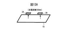
図13A〜図14Bは、無線電力伝送制御方法の第1実施例を説明するための図であり、第1実施例の三次元無線電力伝送システムにおける無線電力伝送制御方法を説明するためのものである。 FIGS. 13A to 14B are diagrams for explaining the first embodiment of the wireless power transmission control method, and are for explaining the wireless power transmission control method in the three-dimensional wireless power transmission system of the first embodiment. is there.
なお、図13A〜図14Bでは、説明を簡略化するために、1つの送電器1Aおよび2つの受電器2A,2Bを示しているが、複数の送電器および3つ以上の受電器であっても同様である。 In FIG. 13A to FIG. 14B, one
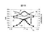
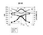
ここで、図13Aおよび図13Bは、送電器1Aから2つの受電器2A,2Bまでの距離が300mmの場合を示し、前述した図10Aおよび図10Bに対応する。また、図14Aおよび図14Bは、送電器1Aから2つの受電器2A,2Bまでの距離が500mmの場合を示し、前述した図11Aおよび図11Bに対応する。 Here, FIGS. 13A and 13B show a case where the distance from the
図13Bおよび図14Bにおいて、参照符号LAは、受電器2Aの受電効率、LBは、受電器2Bの受電効率、PMは、送電器1Aの最大送電出力を示し、RPは、必要送電電力、そして、TPは、全体効率を示す。 In FIG. 13B and FIG. 14B, the reference sign LA is the power receiving efficiency of the
また、参照符号P0は、受電器2A,2Bの要望電力の比が1:1の送電(9W:9W)の場合を示し、P1は、受電器2A,2Bの要望電力の比が2:1の送電(12W:6W)の場合を示す。なお、図13Bおよび図14Bは、電力比1:1を『1.00』に規格化して示す図である。 Reference symbol P0 indicates a case of power transmission (9W: 9W) in which the ratio of the desired power of the
ここで、図13Aおよび図13Bは、前述した図10Aおよび図10Bに対応し、図14Aおよび図14Bは、前述した図11Aおよび図11Bに対応するので、重複する説明は省略する。 Here, FIG. 13A and FIG. 13B correspond to FIG. 10A and FIG. 10B described above, and FIG. 14A and FIG. 14B correspond to FIG. 11A and FIG.
まず、図13Aおよび図13Bのように、送電器1Aから2つの受電器2A,2Bまでの距離が300mmの場合、k値およびQ値は、k=0.0065、および、Q=510となる。このとき、kQ値は、kQ=0.0065×510=3.4として求められる。 First, as shown in FIG. 13A and FIG. 13B, when the distance from the
次に、図14Aおよび図14Bのように、送電器1Aから2つの受電器2A,2Bまでの距離が500mmの場合、k値およびQ値は、k=0.0029、および、Q=510となる。 Next, as shown in FIGS. 14A and 14B, when the distance from the
すなわち、k値は、送電器1Aから受電器2A,2Bまでの距離が300mmから500mmへ長くなるので、磁界(電磁界)の結合の程度は小さく、0.0065から0.0029へ小さくなる。なお、Q値は、磁界(電磁界)の損失の程度は変化しないので、510のままである。 That is, since the distance from the
従って、図14Aおよび図14Bのように、送電器1Aから2つの受電器2A,2Bまでの距離が500mmの場合、kQ値は、kQ=0.0029×510=1.5として求められる。 Therefore, as shown in FIG. 14A and FIG. 14B, when the distance from the
ここで、例えば、kQ値の閾値を『2.0』とし、kQ値が閾値以上(kQ≧2.0)ならば、同時給電(同時電力伝送モード)を選択し、kQ値が閾値よりも小(kQ<2.0)ならば、時分割給電(時分割電力伝送モード)を選択するものとする。このように、本第1実施例によれば、複数の受電器2A,2Bに対して時分割電力伝送および同時電力伝送を切り替えて適切な無線電力伝送を行うことが可能となる。 Here, for example, if the threshold value of the kQ value is “2.0” and the kQ value is equal to or greater than the threshold value (kQ ≧ 2.0), simultaneous power feeding (simultaneous power transmission mode) is selected, and the kQ value is less than the threshold value. If small (kQ <2.0), time-division power supply (time-division power transmission mode) is selected. Thus, according to the first embodiment, it is possible to perform appropriate wireless power transmission by switching between time division power transmission and simultaneous power transmission for the plurality of
ここで、kQ値の閾値は、例えば、『2.0』の辺りを境として、共振条件を可変して電力の配分比を調整する際に全体効率が低下するケースとしないケースが分かれる。そこで、上述した説明では、kQ値の閾値を『2.0』に設定したが、この閾値は、それぞれの製品(受電器)における要望電力や効率および利便性等を考慮して設定することになる。ただし、電力分配においても効率が維持できることを考慮すると、kQ値の閾値は、0.1〜10の範囲、より好ましくは、0.5〜5の範囲に設定することができる。 Here, the threshold value of the kQ value is divided into a case where the overall efficiency is lowered and a case where the overall efficiency is lowered when the resonance condition is changed and the power distribution ratio is adjusted with a boundary around “2.0”, for example. Therefore, in the above description, the threshold value of the kQ value is set to “2.0”, but this threshold value is set in consideration of required power, efficiency, convenience, and the like in each product (power receiver). Become. However, considering that efficiency can be maintained even in power distribution, the threshold value of the kQ value can be set in the range of 0.1 to 10, more preferably in the range of 0.5 to 5.
この結果を利用し、kQ値が閾値以上の場合、電力分配調整を行いながらの同時給電は可能であり、一方で、kQ値が閾値以下の場合は、電力配分比調整を行うことで、全体効率が低下してしまうため、同時給電ではなく、時分割給電を行うことになる。 Using this result, when the kQ value is equal to or greater than the threshold value, simultaneous power feeding is possible while performing power distribution adjustment. On the other hand, when the kQ value is equal to or less than the threshold value, the power distribution ratio adjustment is performed to Since efficiency decreases, time-division power supply is performed instead of simultaneous power supply.
図15A〜図16Bは、無線電力伝送制御方法の第2実施例を説明するための図である。ここで、図15Aおよび図15B、並びに、図16Aおよび図16Bは、両方とも送電器1Aから2つの受電器2A,2Bまでの距離が300mmの場合を示しているが、Q値が異なる場合を示している。なお、図15Bおよび図16Bは、電力比1:1を『1.00』に規格化して示す図である。 15A to 16B are diagrams for explaining a second embodiment of the wireless power transmission control method. Here, FIG. 15A and FIG. 15B and FIG. 16A and FIG. 16B both show the case where the distance from the
まず、図15Aおよび図15Bでは、受電器2A,2Bにおける受電共振コイルの自己インダクタンス(Lr)が大きく、k値およびQ値は、k=0.026、および、Q=600となる。このとき、kQ値は、kQ=0.026×600=15.3として求められる。従って、kQ=15.3≧2.0なので、同時給電(同時電力伝送モード)が選択される。 First, in FIGS. 15A and 15B, the self-inductance (Lr) of the power receiving resonance coil in the
また、図16Aおよび図16Bでは、受電器2A,2Bにおける受電共振コイルの自己インダクタンス(Lr)が小さく、k値およびQ値は、k=0.0065、および、Q=160となる。このとき、kQ値は、kQ=0.0065×160=1.1として求められる。従って、kQ=1.1<2.0なので、時分割給電(時分割電力伝送モード)が選択される。 In FIG. 16A and FIG. 16B, the self-inductance (Lr) of the power receiving resonance coil in the
このように、本実施例の無線電力伝送制御方法(無線電力伝送システム)によれば、例えば、kQ値を評価指標とすることにより、同時給電と時分割給電のどちらが適切かを判断してワイヤレス給電を行うことが可能となる。 As described above, according to the wireless power transmission control method (wireless power transmission system) of the present embodiment, for example, by using the kQ value as an evaluation index, it is determined whether simultaneous power feeding or time division power feeding is appropriate. Power can be supplied.
なお、k値は、例えば、送電器1Aと受電器2A(2B)間における仕様情報、および、送電器1Aと受電器2A(2B)間における相対位置関係に基づいて算出することができ、また、Q値は、それぞれの受電器により予め規定されている。 The k value can be calculated based on, for example, specification information between the
図17は、本実施例の無線電力伝送システムの一例を示すブロック図であり、2つの送電器1A,1B、および、2つの受電器2A,2Bを含む例を示すものである。図17に示されるように、送電器1A,1Bは同様の構成を有し、それぞれワイヤレス送電部11A,11B、高周波電源部12A,12B、送電制御部13A,13Bおよび通信回路部14A,14Bを含む。 FIG. 17 is a block diagram illustrating an example of a wireless power transmission system according to the present embodiment, and illustrates an example including two
高周波電源部12A,12Bは、高周波の電力を発生するもので、例えば、前述した図3における高周波電源部12に相当し、固有の電源インピーダンスを有する。例えば、出力インピーダンスが50Ωに整合された定電圧電源や、高い出力インピーダンスのHi−ZΩ電源(定電流電源)などである。 The high frequency
送電制御部13A,13Bは、送電部11A,11Bを制御し、通信回路部14A,14Bは、各送電器および受電器間の通信を可能とするものであり、例えば、IEEE 802.11bに準拠するDSSS方式の無線LANやブルートゥース(Bluetooth(登録商標))を利用することができる。 The power
なお、高周波電源部12A,12Bは、それぞれ外部電源10A,10Bから電力の供給を受け取り、送電制御部13A,13Bには、検出部SA,SBからの信号が入力されている。なお、送電器1Aおよび送電器1Bは、例えば、1つの送電器1に設けた2つの送電部(11)としてもよいのはいうまでもない。 The high frequency
ワイヤレス送電部11A,11Bは、磁界共鳴であればコイルに相当し、高周波電源部12A,12Bから供給される高周波電力を磁界に変換する。検出部SA,SBは、送電器1A,1Bの相対位置関係や受電器2A,2Bの相対位置関係を検出する。 The wireless
なお、例えば、送電器1A,1Bの位置関係が固定され(送電共振コイル11a1,11a2が特定のL字ブロック状に固定され)、その情報を送電制御部13A,13Bが把握し、受電器2A,2Bが検出機能を有する場合、検出部SA,SBは省略可能である。 In addition, for example, the positional relationship between the
受電器2A,2Bも同様の構成を有し、それぞれワイヤレス受電部21A,21B、整流部(受電回路部)22A,22B、受電制御部23A,23B、通信回路部24A,24Bおよび機器本体(バッテリ部)25A,25Bを含む。 The
受電制御部23A,23Bは、受電器2A,2Bを制御するものであり、通信回路部24A,24Bは、各送電器および受電器間の通信を可能とするもので、前述したように、例えば、無線LANやブルートゥース(Bluetooth(登録商標))を利用する。 The power
ワイヤレス受電部21A,21Bは、磁界共鳴であればコイルに相当し、無線で伝達された電力を電流に変換する。整流部22A,22Bは、ワイヤレス受電部21A,21Bから得られた交流電流をバッテリ充電や機器本体で使用可能なように直流電流に変換する。 The wireless
上述したように、送電器1A,1Bおよび受電器2A,2Bは、それぞれの通信回路部14A,14B,24A,24Bを介して通信を行う。このとき、例えば、送電器1Aをマスタ(全体制御器)とし、このマスタ(送電器)1Aが、他の送電器1Bおよび受電器2A,2Bをスレーブとして制御することもできる。 As described above, the
ここで、送電器1A,1Bの通信回路部14A,14B、並びに、受電器2A,2Bの通信回路部24A,24Bを介した通信により、同時送電と時分割送電の切り替え、並びに、同時送電における電力配分比調整等の制御を行う。 Here, in communication via the
具体的に、例えば、送電器1Aの通信回路部14Aおよび受電器2A,2Bの通信回路部24A,24Bを介して、それぞれの受電器2A,2BにおけるQ値を、無線電力伝送の制御を行うマスタ(例えば、送電器1A)に通信で伝える。 Specifically, for example, the Q value in each of the
また、同時給電を行う場合、例えば、送電器1Aの通信回路部14Aおよび受電器2Bの通信回路部24Bを介して、受電器2Bの受電共振コイルにおける容量のキャパシタンス(CA)を共振点からずらし、電力配分比の調整を行う。具体的に、前述した図5Aに示す受電共振コイル21aにおける容量212のキャパシタンスの値を制御して、受電器2A,2Bの電力配分比を調整する。In the case of simultaneous power feeding, for example, the capacitance (CA ) of the capacitance in the power receiving resonance coil of the
さらに、時分割給電を行う場合、例えば、送電器1Aの通信回路部14Aおよび受電器2A,2Bの通信回路部24A,24Bを介して、ワイヤレス給電を行う受電器の切り替えを行う。 Furthermore, when performing time-sharing power supply, for example, the power receiver that performs wireless power supply is switched via the
具体的に、例えば、前述した図5Aに示す受電共振コイル21aにおけるスイッチ213を制御して、ワイヤレス給電を行う受電器のスイッチ213だけを順にオンするように制御する。或いは、例えば、前述した図5Bに示す受電共振コイル21aにおけるスイッチ213を制御して、ワイヤレス給電を行う受電器のスイッチ213だけを順にオフするように制御する。 Specifically, for example, the
なお、ワイヤレス送電部11Aおよび11Bと、ワイヤレス受電部21Aまたは21Bの間は、磁界共鳴を利用した電力伝送に限定されるものではなく、例えば、電界共鳴、或いは、電磁誘導や電界誘導を利用した電力伝送方式を適用することもできる。 Note that the power transmission between the wireless
次に、受電器が3つ以上ある場合において、kQ値をグループ分けする場合を説明する。図18は、無線電力伝送制御方法の第3実施例を説明するための図であり、評価指標のグループ分けを説明するためのものである。なお、図18では、1つの送電器1Aおよび6個の受電器2A〜2Fを例として示しているが、これは単なる例であり、様々な場合があり得るのはいうまでもない。 Next, a case where kQ values are grouped when there are three or more power receivers will be described. FIG. 18 is a diagram for explaining a third embodiment of the wireless power transmission control method, and is for explaining grouping of evaluation indexes. In FIG. 18, one
図18に示されるように、第3実施例の無線電力伝送制御方法は、複数(6個)の受電器2A〜2FのkQ値(評価指標)を評価し、kQ値によりグループ分けを行う。まず、全ての受電器2A〜2Fを、それぞれ単体評価する。 As shown in FIG. 18, the wireless power transmission control method of the third embodiment evaluates the kQ values (evaluation indices) of a plurality (six) of the
例えば、受電器2Aを評価するとき、受電器2Aのみオンして、他の受電器2B〜2Fをオフ(例えば、図5Aの受電共振コイル21aにおけるスイッチ213をオフ)する。そして、例えば、kQ値が最大(kQmax1)となる受電器2Bを基準とし、他の受電器のkQ値(kQother)に関して、kQother/kQmax1が一定値以上ならば、同一グループとする。具体的に、図18では、kQ値がkQ1-1の受電器2FおよびkQ値がkQ1-2の受電器2Cが、第1グループGP1とされている。For example, when evaluating the
次に、kQ値が最大(kQmax1)となる受電器2Bを含む第1グループGP1以外の受電器2A,2D,2Eにおいて、kQ値が最大(kQmax2)となる受電器2Aを基準として、同様にグループ分けを行う。具体的に、図18では、受電器2A,2D,2Eが、第2グループGP2とされている。そして、分割されたグループGP1,GP2を単位として、同一グループ内では同時給電を行い、異なるグループ間では、後に詳述するように、個別に検討する。Next, in the
ところで、一般的に、ワイヤレス送電可能なシステムの要件として、電力と効率は、比例する関係が好ましい。つまり、大電力を送電するシステムでは、高効率が望まれ、また、小電力を送電するシステムでは、低効率であっても許容することができる。これは、特に、ロスが結果として発熱になるため、放熱の問題を考えれば容易に理解することができる。 By the way, in general, as a requirement of a system capable of wireless power transmission, a proportional relationship between power and efficiency is preferable. That is, high efficiency is desired in a system that transmits high power, and low efficiency is acceptable in a system that transmits low power. This can be easily understood especially when considering the problem of heat dissipation since loss results in heat generation.
すなわち、大電力系において効率が低い場合には、放熱すべき電力が大きくなるため、システムを構築することが難しくなるためである。言い換えれば、送電電力に応じて、許容効率が規定されていると考えることもできる。 That is, when the efficiency is low in a large power system, the power to be dissipated becomes large, making it difficult to construct a system. In other words, it can be considered that the allowable efficiency is defined according to the transmission power.
そのような状況で、kQ値が異なる複数の受電器に対した、同時給電すべきか、或いは、時分割給電すべきかを検討すると、送電完了時間を優先すれば、同時給電が常に望ましいと考えられるが、上述したように、許容できる効率は各系に応じて異なっている。 In such a situation, when considering whether simultaneous power feeding or time-sharing power feeding should be performed for a plurality of power receivers having different kQ values, if power transmission completion time is given priority, simultaneous power feeding is always desirable. However, as described above, the allowable efficiency differs depending on each system.
そこで、許容効率を確保しつつ、同時給電を行うことのできる方法を考えるのが現実的であり、本実施例では、kQ値の近いものをグループ化し、そのグループ内では同時給電を優先し、グループ外では時分割給電を優先するようになっている。 Therefore, it is realistic to consider a method capable of performing simultaneous power feeding while ensuring allowable efficiency, and in this embodiment, those having similar kQ values are grouped, and priority is given to simultaneous power feeding within the group, Outside the group, priority is given to time-sharing power supply.
これは、kQ値が同じ(近い)ものの同時給電であれば、Q値を少し可変することで電力のバランスを調整することが容易である一方で、kQ値が大きく異なっているものの同時給電では、バランス調整のために、Q値を大きく低下させることになる。これは、結果として、全体の効率低下を招くことになる。 This is because it is easy to adjust the balance of power by slightly changing the Q value if the kQ values are the same (near), but the simultaneous power feeding is very different in kQ values. Therefore, the Q value is greatly reduced for balance adjustment. This results in a decrease in overall efficiency.
一例として、ノートパソコン群とスマートフォン群への給電を考える。ここで、ノートパソコン群(ノートパソコン)は、例えば、30Wの給電を要求し(要望電力が30Wであり)、その電力の大きさゆえに許容最低効率は80%とする。また、ノートパソコンは、サイズが大きいために受電コイルを大きくすることができ、kQ値を大きくすることが可能である。 As an example, consider power supply to notebook computers and smartphones. Here, the notebook personal computer group (note personal computer) requires, for example, power supply of 30 W (requested power is 30 W), and the allowable minimum efficiency is 80% because of the magnitude of the power. In addition, since the notebook computer is large in size, the power receiving coil can be enlarged, and the kQ value can be increased.
一方、スマートフォン群(スマートフォン)は、例えば、5Wの給電を要求し(要望電力が5Wであり)、許容効率は40%とする。また、スマートフォンは、サイズが小さく、位置がより自由であるため、kQ値は小さく抑えられてしまう。 On the other hand, the smartphone group (smartphone) requests, for example, 5 W power supply (the requested power is 5 W), and the allowable efficiency is 40%. In addition, since the smartphone is small in size and more free in position, the kQ value is kept small.
このような2つの郡への同時給電を行うと、kQ値が異なるグループへの同時給電となるが、ノートパソコン群への給電ばかりが実行され、スマートフォン群へ電力が届かないことになる。 If simultaneous power supply to such two counties is performed, simultaneous power supply to groups having different kQ values is performed, but only power supply to the notebook computer group is executed, and power does not reach the smartphone group.
このとき、例えば、Q値を低下させて電力のバランスを取ることもできるが、その場合には、全体の効率が低下してしまい、ノートパソコンを含む給電の効率が低くなり、例えば、許容効率が80%以下となってしまうこともあり得る。 At this time, for example, the Q value can be lowered to balance the power, but in that case, the overall efficiency is lowered, and the power supply efficiency including the notebook computer is lowered. May be 80% or less.
そのため、kQ値が異なるグループへの同時給電は好ましくないことが分かる。すなわち、kQ値(評価指標)が設定値以上となる受電器が3つ以上存在するとき、そのkQ値の大きさに基づいてグループ分けを行うが、近いkQ値を持つ受電器が同じグループとなるようにグループ分けを行うのが好ましい。 Therefore, it can be seen that simultaneous power feeding to groups having different kQ values is not preferable. That is, when there are three or more power receivers whose kQ value (evaluation index) is equal to or greater than the set value, grouping is performed based on the magnitude of the kQ value. It is preferable to perform grouping so that
ここで、kQ値によりグループ分けされた受電器に関して、例えば、閾値以下となるグループの受電器に対しては、時分割給電を行うことになる。また、閾値以上となるグループの受電器に対して、同一グループ内の給電では、電力分配を調整して同時給電を行うことができ、異なるグループにまたがる受電器に対しては、時分割給電を行うのが好ましい。 Here, with respect to the power receivers grouped by the kQ value, for example, time-division power feeding is performed for the power receivers of a group that is equal to or less than the threshold value. In addition, for power receivers in groups that exceed the threshold value, power can be fed simultaneously by adjusting power distribution for power supply within the same group, and time-division power supply can be performed for power receivers across different groups. It is preferred to do so.
なお、複数の受電器をkQ値により複数のグループに分けるための閾値としては、想定される無線電力伝送システムの規模や仕様により様々に変化させることができ、それに従って、グループの数や各グループに含まれる受電器の数も変化することになる。 Note that the threshold for dividing a plurality of power receivers into a plurality of groups based on kQ values can be variously changed according to the assumed size and specifications of the wireless power transmission system, and accordingly, the number of groups and each group This also changes the number of power receivers included in.
図19は、第3実施例の無線電力伝送制御方法による処理の一例を説明するためのフローチャートである。図19に示されるように、第3実施例の無線電力伝送制御方法による処理が開始すると、ステップST1において、各受電器のkQ値を評価し、kQ<[基準1(第1設定値)]とされた受電器(ステップST2)に対しては、ステップST3に進んで、時分割給電を行う。 FIG. 19 is a flowchart for explaining an example of processing by the wireless power transmission control method of the third embodiment. As shown in FIG. 19, when the processing by the wireless power transmission control method of the third embodiment starts, in step ST1, the kQ value of each power receiver is evaluated, and kQ <[reference 1 (first set value)]. For the received power receiver (step ST2), the process proceeds to step ST3 to perform time-sharing power supply.
一方、kQ≧[基準1]とされた受電器(ステップST4)に対しては、ステップST5に進んで、受電器をkQ値によりグループ分けを行う。そして、同一グループ内のみの受電器(ステップST6)に対しては、ステップST7に進んで、同時給電を行う。 On the other hand, for power receivers (step ST4) for which kQ ≧ [reference 1], the process proceeds to step ST5, where the power receivers are grouped according to kQ values. And it progresses to step ST7 with respect to the power receiver only in the same group (step ST6), and simultaneous electric power feeding is performed.
また、グループ間の給電がある受電器(ステップST8)に対しては、ステップST9に進んで、電力分配による効率低下を評価する。 Further, for a power receiver (step ST8) that has power supply between groups, the process proceeds to step ST9, and an efficiency reduction due to power distribution is evaluated.
そして、効率(予想効率)<[基準2(第2設定値)]とされた受電器(ステップST10)に対しては、ステップST11に進んで、時分割給電を行う。一方、効率≧[基準2]とされた受電器(ステップST12)に対しては、ステップST13に進んで、同時給電を行う。 For the power receiver (step ST10) in which efficiency (expected efficiency) <[reference 2 (second set value)], the process proceeds to step ST11 and time-division power feeding is performed. On the other hand, for the power receiver (step ST12) in which efficiency ≧ [reference 2] is established, the process proceeds to step ST13 to perform simultaneous power feeding.
図20〜図22は、図19に示すフローチャートにおける処理に対応した複数の受電器を説明するための図である。ここで、上述したフローチャートのステップST2およびST4において、kQ値を判定する[基準1(kQ基準1:第1設定値)]=1.5とし、ステップST10およびST12において、効率を判定する[基準2(判定基準2:第2設定値)]=0.2とする。 20-22 is a figure for demonstrating the several power receiving device corresponding to the process in the flowchart shown in FIG. Here, in steps ST2 and ST4 of the flowchart described above, the kQ value is determined [reference 1 (kQ reference 1: first set value)] = 1.5, and the efficiency is determined in steps ST10 and ST12 [reference. 2 (judgment criterion 2: second set value)] = 0.2.
まず、図20に示されるように、例えば、受電器が3個の場合(2A〜2C)を説明する。ここで、受電器2AのkQ値は1.2、受電器2BのkQ値は8.5、そして、受電器2CのkQ値は8.2とする。 First, as shown in FIG. 20, for example, a case where there are three power receivers (2A to 2C) will be described. Here, the kQ value of the
このとき、受電器2Aは、kQ値(1.2)<kQ基準1(1.5)となるため、ステップST3に進んで、複数同時給電の対象外とされて、時分割給電が選択される。一方、受電器2B,2Cは、それぞれのkQ値(8.5,8.2)≧kQ基準1(1.5)となるため、ステップST5に進む。すなわち、受電器2B,2Cは、同時給電の対象候補となる。 At this time, since the
ここで、受電器2B,2Cは、ステップST6において、kQ値のグループ分けにより同一グループと判断できる。すなわち、同時給電の対象候補の受電器2B,2Cは、同一グループのみであるとして、ステップST7に進んで同時給電が行われる。このとき、受電器2Bおよび2Cは、例えば、要望電力に基づいて受電共振コイルによる共振点をずらし、電力分配を行うことができる。 Here, the
このように、図20の場合には、例えば、受電器2Aを単独で給電する第1給電セット、受電器2B,2Cを同時給電する第2給電セットを、時分割的に切り替えて時分割給電を行うことになる。 Thus, in the case of FIG. 20, for example, the first power supply set that supplies power alone to the
なお、時分割的に切り替えて行う給電は、例えば、第1給電セット完了後に、第2給電セットを行ってもよいが、一定時間だけ第1給電セットを行った後、一定時間だけ第2給電セットを行い、この処理を交互に繰り返すようにしてもよい。 For example, the second power supply set may be performed after the first power supply set is completed. However, after the first power supply set is performed for a predetermined time, the second power supply is performed for a predetermined time. It is also possible to set and repeat this process alternately.
次に、図21に示されるように、例えば、受電器が5個の場合(2A〜2E)を説明する。ここで、受電器2AのkQ値は1.2、受電器2BのkQ値は8.5、受電器2CのkQ値は8.2、受電器2DのkQ値は3.1、そして、受電器2EのkQ値は3.4とする。 Next, as shown in FIG. 21, for example, a case where there are five power receivers (2A to 2E) will be described. Here, the kQ value of the
このとき、受電器2Aは、kQ値(1.2)<kQ基準1(1.5)となるため、ステップST3に進んで、複数同時給電の対象外とされて、時分割給電が選択される。一方、受電器2B〜2Eは、それぞれのkQ値(8.5,8.2,3.1,3.4)≧kQ基準1(1.5)となるため、ステップST5に進み、kQ値によるグループ分けを行う。 At this time, since the
このkQ値によるグループ分けにより、例えば、受電器2B,2Cは、kQ値が8.5,8.2となっているため、同一グループとされ、また、受電器2D,2Eは、kQ値が3.1,3.4となっているため、同一グループとされる。 By this grouping by the kQ value, for example, the
すなわち、ステップST8に進んで、同時給電の対象候補が複数グループ(受電器2B,2Cと、受電器2D,2Eの2つのグループ)存在すると判定し、ステップST9に進んで、電力分配による効率低下を評価する。 That is, the process proceeds to step ST8, where it is determined that there are multiple groups (two groups of the
具体的に、受電器2B,2Cのグループと、受電器2D,2Eのグループを同時給電した場合の最低効率を評価する。例えば、最低効率(効率)が0.15の場合には、ステップST10で、効率(0.15)<効率基準2(第2設定値:0.2)なので送電効率の低下は許容値を超えると判定してステップST11に進み、時分割給電を行う。 Specifically, the minimum efficiency when the group of the
このように、図21の場合には、例えば、次の3つの給電セットを時分割給電する。すなわち、受電器2Aを単独で給電する第1給電セット、受電器2B,2Cを同時給電する第2給電セット、並びに、受電器2D,2Eを同時給電する第3給電セットを時分割的に切り替えて給電を行う。 Thus, in the case of FIG. 21, for example, the following three power supply sets are time-divisionally supplied. That is, the first power supply set that supplies power to the
図22は、上述した図21と同様に、受電器が5個の場合(2A〜2E)であり、各受電器2A〜2EのkQ値も図21と共通である。ただし、図22では、最低効率が、図21の0.15よりも大きい0.25となっている。従って、図22の場合、図19のフローチャートにおけるステップST1〜ST9の処理は、図21の場合と同様である。 FIG. 22 shows the case where there are five power receivers (2A to 2E), similarly to FIG. 21 described above, and the kQ values of the
すなわち、ステップST9において、電力分配による効率低下を評価するが、受電器2B,2Cのグループと、受電器2D,2Eのグループを同時給電した場合の最低効率は、0.25となっている。 That is, in step ST9, efficiency reduction due to power distribution is evaluated, but the minimum efficiency when the
この最低効率(効率)が0.25の場合には、ステップST12で、効率(0.25)≧効率基準2(第2設定値:0.2)なので、送電効率の低下は許容値内であると判定してステップST13に進み、同時給電を行うことになる。なお、同時給電において、各受電器の要望電力に基づいた電力分配を行うことができるのはいうまでもない。 When this minimum efficiency (efficiency) is 0.25, since efficiency (0.25) ≧ efficiency standard 2 (second set value: 0.2) in step ST12, the reduction in power transmission efficiency is within an allowable value. It is determined that there is, and the process proceeds to step ST13 to perform simultaneous power feeding. Needless to say, in the simultaneous power feeding, power distribution based on the desired power of each power receiver can be performed.
このように、図22の場合には、例えば、次の2つの給電セットを時分割給電する。すなわち、受電器2Aを単独で給電する第1給電セット、並びに、受電器2B〜2Eを同時給電する第2給電セットを時分割的に切り替えて給電を行う。 Thus, in the case of FIG. 22, for example, the following two power supply sets are time-divisionally supplied. That is, power supply is performed by switching the first power supply set that supplies power to the
以上の説明では、1つの送電器1A、並びに、3〜6個の受電器2A〜2Fを含む無線電力伝送システムを例として説明したが、送電器は、例えば、異なる角度で複数設けることができ、また、受電器も様々な数,距離および姿勢(角度)であってもよい。 In the above description, the wireless power transmission system including one
図23〜図25は、本実施形態の無線電力伝送制御方法における事前演算データの一例を説明するための図である。ここで、図23は、第1グループのkQ値と、第2グループのkQ値をプロットしたテーブルであり、図24は、例えば、図23のテーブルにおけるD0710の個所を示すテーブルである。そして、図25は、例えば、図24のテーブルにおけるE0611の個所に設定された値を示す。 23 to 25 are diagrams for explaining an example of pre-computed data in the wireless power transmission control method of the present embodiment. Here, FIG. 23 is a table in which the kQ values of the first group and the kQ values of the second group are plotted, and FIG. 24 is a table showing the location of D0710 in the table of FIG. 23, for example. FIG. 25 shows values set at the location E0611 in the table of FIG. 24, for example.
図23に示されるように、本実施形態の無線電力伝送制御方法において、例えば、第1グループのkQ値が『10』で第2グループのkQ値が『7』の場合のために、このようなkQ値を有する2つのグループに対して、予め、[D0710]を準備しておく。 As shown in FIG. 23, in the wireless power transmission control method according to the present embodiment, for example, when the kQ value of the first group is “10” and the kQ value of the second group is “7”, [D0710] is prepared in advance for two groups having different kQ values.
なお、[D0710]は単なる例であり、第1および第グループのそれぞれのkQ値に対して同様のものを準備しておく。また、図23における参照符号WWで示した個所は、kQ値が所定値以下で電力分配が不可の領域を示す。 [D0710] is merely an example, and similar ones are prepared for the kQ values of the first and first groups. Further, the part indicated by reference numeral WW in FIG. 23 indicates an area where the kQ value is equal to or less than a predetermined value and power distribution is not possible.
次に、図24に示されるように、例えば、第1グループのkQ値が『10』で第2グループのkQ値が『7』のときの[D0710]において、例えば、2つの受電器に対する電力の配分比を3:2に制御する場合のために、予め、[E0611]を準備しておく。なお、[E0611]も単なる例であり、様々な配分比に対して同様のものを準備しておく。 Next, as shown in FIG. 24, for example, in [D0710] when the kQ value of the first group is “10” and the kQ value of the second group is “7”, for example, the power for the two power receivers [E0611] is prepared in advance for the case where the distribution ratio is controlled to 3: 2. [E0611] is merely an example, and similar ones are prepared for various distribution ratios.
さらに、図25に示されるように、例えば、[D0710]において電力の配分比を3:2にする[E0611]として、受電器2A,2Bの共振周波数および予想全体効率等を、予め準備しておく。 Furthermore, as shown in FIG. 25, for example, the power distribution ratio in [D0710] is set to 3: 2 [E0611], and the resonance frequency and the expected overall efficiency of the
通常、受電器2A,2Bは、固定の共振周波数(6.78MHz)で受電しているが、例えば、受電器2A,2Bの要望電力に従って、受電器2A:2Bの電力比を3:2に設定したい場合、受電器2Bの共振周波数を6.75MHzにずらせばよいことが分かる。さらに、このときの予想全体効率が67%程度であることも確認することができる。 Normally, the
なお、図23〜図25に示す事前演算データは、例えば、予め、シミュレーションや演算等を行って様々な条件に対応するデータを事前に演算し、例えば、送電器のテーブル(ルックアップテーブル)としてメモリに格納しておくことができる。 The pre-computation data shown in FIG. 23 to FIG. 25 is, for example, pre-calculated data corresponding to various conditions by performing simulation or computation in advance, for example, as a transmitter table (look-up table) Can be stored in memory.
以上の説明において、送電器および受電器は、主として1つまたは2つとして説明したが、それぞれさらに多数であってもよい。また、各実施例の説明は、主として磁界共鳴を利用した電力伝送を例としたが、本実施形態は、電界共鳴を利用した電力伝送に対しても適用することができる。 In the above description, the number of power transmitters and power receivers has been mainly described as one or two. In addition, although the description of each example has been made mainly on power transmission using magnetic field resonance, this embodiment can also be applied to power transmission using electric field resonance.
ここに記載されている全ての例および条件的な用語は、読者が、本発明と技術の進展のために発明者により与えられる概念とを理解する際の助けとなるように、教育的な目的を意図したものである。 All examples and conditional terms contained herein are intended for educational purposes only to assist the reader in understanding the present invention and the concepts provided by the inventor for the advancement of technology. Is intended.
また、具体的に記載されている上記の例および条件、並びに、本発明の優位性および劣等性を示すことに関する本明細書における例の構成に限定されることなく、解釈されるべきものである。 Further, the present invention should not be construed as being limited to the above-described examples and conditions specifically described, and the configurations of the examples in the present specification regarding the superiority and inferiority of the present invention. .
さらに、本発明の実施例は詳細に説明されているが、本発明の精神および範囲から外れることなく、様々な変更、置換および修正をこれに加えることが可能であると解すべきである。 Further, while embodiments of the present invention have been described in detail, it should be understood that various changes, substitutions and modifications can be made thereto without departing from the spirit and scope of the present invention.
1 送電器(一次側:送電側)
1A〜1D,1A1〜1A3 送電器
2 受電器(二次側:受電側)
2A〜2F,2A1〜2A3,2B1〜2B3,2C1,2C2 受電器
10A,10B 外部電源
11,11A,11B ワイヤレス送電部
11a,11aA,11aB、11a1,11a2 送電共振コイル(第2コイル:LC共振器)
11b 電力供給コイル(第1コイル)
12,12A,12B 高周波電源部
13,13A,13B 送電制御部
14,14A,14B 通信回路部(第1通信回路部)
21,21A,21B ワイヤレス受電部
21a 受電共振コイル(第3コイル:LC共振器)
21b 電力取出コイル(第4コイル)
22,22A,22B 受電回路部(整流部)
23,23A,23B 受電制御部
24 通信回路部(第2通信回路部)
25,25A,25B バッテリ部(機器本体,負荷)
GP1 第1グループ
GP2 第2グループ1 Power transmitter (primary side: power transmission side)
1A to 1D, 1A1 to
2A-2F, 2A1-2A3, 2B1-2B3, 2C1,
11b Power supply coil (first coil)
12, 12A, 12B High frequency
21, 21A, 21B Wireless
21b Power extraction coil (4th coil)
22, 22A, 22B Power receiving circuit (rectifier)
23, 23A, 23B Power
25, 25A, 25B Battery (device body, load)
GP1 first group GP2 second group
この出願で言及する実施例は、無線電力伝送制御方法および無線電力伝送システムに関する。 The embodiments mentioned in this application relate to a wireless power transmission control method and a wireless power transmission system.
近年、電源供給や充電を行うために、無線で電力を伝送する技術が注目されている。例えば、携帯端末やノートパソコンを始めとした様々な電子機器や家電機器、或いは、電力インフラ機器に対して、無線で電力伝送を行う無線電力伝送システムが研究・開発されている。 In recent years, in order to perform power supply and charging, a technique for transmitting power wirelessly has attracted attention. For example, wireless power transmission systems that wirelessly transmit power to various electronic devices such as mobile terminals and notebook computers, home appliances, and power infrastructure devices are being researched and developed.
ところで、無線電力伝送(ワイヤレス電力伝送:Wireless Power Transfer)を利用する場合、電力を送る側の送電器と、送電器から送られた電力を受け取る側の受電器がそれぞれ異なるメーカの製品であっても支障なく使用するために標準化を行うのが好ましい。 By the way, when using wireless power transfer (Wireless Power Transfer), the transmitter on the side that sends power and the receiver on the side that receives the power sent from the transmitter are products of different manufacturers. However, it is preferable to perform standardization so that it can be used without any problem.
従来、無線による電力伝送技術としては、一般的に、電磁誘導を利用した技術や電波を利用した技術が知られている。 Conventionally, as a wireless power transmission technique, a technique using electromagnetic induction and a technique using radio waves are generally known.
そして、近年、送電器と受電器の距離をある程度離しつつ、複数の受電器に対する電力伝送および受電器の三次元的な様々な姿勢に対する電力伝送が可能なものとして、強結合系の共振を用いたワイヤレス送電技術が注目されている。 In recent years, the resonance of a strongly coupled system has been used to enable power transmission to a plurality of power receivers and three-dimensional various postures of the power receivers while maintaining a certain distance between the power transmitter and the power receiver. Wireless power transmission technology that has been attracting attention.
この強結合系の共振を用いたワイヤレス送電としては、例えば、磁界共鳴(磁界共振)や電界共鳴(電界共振)を利用した無線電力伝送技術が知られている。 As wireless power transmission using the resonance of the strong coupling system, for example, a wireless power transmission technique using magnetic field resonance (magnetic field resonance) or electric field resonance (electric field resonance) is known.
従来、無線電力伝送技術としては、様々な提案がなされている。 Conventionally, various proposals have been made for wireless power transmission technology.
前述したように、従来、電源供給や充電を行うために無線で電力を伝送する無線電力伝送技術が注目されている。この無線電力伝送技術を適用した無線電力伝送システムは、通常、複数の受電器に対して電力を伝送するが、各受電器が要望する電力、或いは、送電器に対する各受電器の位置関係等に基づいた電力伝送制御が求められている。 As described above, conventionally, wireless power transmission technology that wirelessly transmits power for power supply and charging has attracted attention. A wireless power transmission system to which this wireless power transmission technology is applied normally transmits power to a plurality of power receivers. However, the power requested by each power receiver or the positional relationship of each power receiver with respect to the power transmitter, etc. There is a need for power transmission control based on this.
この送電器から複数の受電器への電力伝送としては、受電器ごとに電力伝送を行う時分割電力伝送、並びに、複数の受電器に対して同時に電力伝送を行う同時電力伝送がある。しかしながら、複数の受電器を含む無線電力伝送システムにおいて、それぞれの受電器に対して評価指標を設定し、その評価指標に基づいて無線電力伝送を行うことは行われておらず、各受電器に対して適切な無線電力伝送を行うことが困難であった。 As power transmission from this power transmitter to a plurality of power receivers, there are time-division power transmission that performs power transmission for each power receiver and simultaneous power transmission that performs power transmission to a plurality of power receivers simultaneously. However, in a wireless power transmission system including a plurality of power receivers, an evaluation index is set for each power receiver, and wireless power transmission is not performed based on the evaluation index. However, it has been difficult to perform appropriate wireless power transmission.
一実施形態によれば、少なくとも1つの送電器、および、少なくとも2つの受電器を含み、前記送電器からの電力を、磁界共鳴または電界共鳴を利用して無線により、それぞれの前記受電器に伝送する無線電力伝送制御方法が提供される。 According to one embodiment, including at least one power transmitter and at least two power receivers, the power from the power transmitter is transmitted to each of the power receivers wirelessly using magnetic field resonance or electric field resonance. A wireless power transmission control method is provided.
前記無線電力伝送制御方法は、複数の前記受電器に対して、同時に電力を伝送する同時電力伝送モードと、前記受電器に対して、時分割的に切り替えて順番に電力を伝送する時分割電力伝送モードと、を有する。 The wireless power transmission control method includes a simultaneous power transmission mode in which power is simultaneously transmitted to a plurality of the power receivers, and time-division power in which power is sequentially transmitted to the power receivers in a time-sharing manner. A transmission mode.
前記無線電力伝送制御方法は、それぞれの前記受電器に評価指標を設定し、前記評価指標に基づいて、前記同時電力伝送モードおよび前記時分割電力伝送モードを切り替えて無線電力伝送を行う。 In the wireless power transmission control method, an evaluation index is set for each of the power receivers, and wireless power transmission is performed by switching between the simultaneous power transmission mode and the time division power transmission mode based on the evaluation index.
開示の無線電力伝送制御方法および無線電力伝送システムは、複数の受電器に対して時分割電力伝送および同時電力伝送を切り替えて適切な無線電力伝送を行うことができるという効果を奏する。 The disclosed wireless power transmission control method and wireless power transmission system have an effect that appropriate wireless power transmission can be performed by switching time-division power transmission and simultaneous power transmission to a plurality of power receivers.
まず、無線電力伝送制御方法および無線電力伝送システムの実施例を詳述する前に、電力伝送システムの例、並びに、複数の送電器および受電器を含む関連技術の無線電力伝送システムを、図1〜図11Cを参照して説明する。 First, before describing embodiments of the wireless power transmission control method and the wireless power transmission system in detail, an example of a power transmission system and a related-art wireless power transmission system including a plurality of power transmitters and power receivers will be described with reference to FIG. This will be described with reference to FIG.
図1Aは、有線電力伝送(ワイヤー接続給電)システムの一例を模式的に示す図であり、図1Bは、無線電力伝送(ワイヤレス給電)システムの一例を模式的に示す図である。図1Aおよび図1Bにおいて、参照符号2A1〜2C1は、それぞれ受電器を示す。 FIG. 1A is a diagram schematically illustrating an example of a wired power transmission (wire connection feeding) system, and FIG. 1B is a diagram schematically illustrating an example of a wireless power transmission (wireless feeding) system. 1A and 1B, reference numerals 2A1 to 2C1 denote power receivers, respectively.
ここで、受電器2A1は、例えば、要望電力が10Wのタブレットコンピュータ(タブレット)を示し、受電器2B1は、例えば、要望電力が50Wのノートパソコンを示し、受電器2C1は、例えば、要望電力が2.5Wのスマートフォンを示す。なお、要望電力は、例えば、それぞれの受電器2A1〜2C1における充電池(二次電池)を充電するための電力に相当する。 Here, the power receiver 2A1 indicates, for example, a tablet computer (tablet) having a required power of 10 W, the power receiver 2B1 indicates, for example, a notebook computer having a required power of 50 W, and the power receiver 2C1 has a required power of, for example, A 2.5 W smartphone is shown. In addition, request | requirement electric power is corresponded to the electric power for charging the rechargeable battery (secondary battery) in each power receiving device 2A1-2C1, for example.
図1Aに示されるように、通常、タブレット2A1やスマートフォン2C1の二次電池を充電する場合、例えば、パソコン(Personal Computer)のUSB(Universal Serial Bus)端子(または、専用電源等)3Aに対して電源ケーブル4A,4Cを介して接続する。また、ノートパソコン2B1の二次電池を充電する場合、例えば、専用の電源装置(AC-DC Converter)3Bに対して電源ケーブル4Bを介して接続する。 As shown in FIG. 1A, when the secondary battery of the tablet 2A1 or the smartphone 2C1 is normally charged, for example, with respect to a USB (Universal Serial Bus) terminal (or a dedicated power source) 3A of a personal computer. Connection is made via
すなわち、図1Aに示されるように、携帯可能な受電器2A1〜2C1であっても、一般的に、電源ケーブル4A〜4Cを使用してUSB端子3Aや電源装置3Bからワイヤー接続給電(有線電力伝送)を行っている。 That is, as shown in FIG. 1A, even if the portable power receivers 2A1 to 2C1 are used, generally, the
ところで、近年、電磁誘導に代表される非接触給電技術の進歩により、例えば、シェーバーや電動歯ブラシ等でワイヤレス給電(無線電力伝送)が実用化されている。そこで、図1Bに示されるように、例えば、送電器1A1から、タブレット2A1,ノートパソコン2B1およびスマートフォン2C1に対して無線電力伝送することが考えられている。 By the way, in recent years, wireless power feeding (wireless power transmission) has been put into practical use, for example, with a shaver, an electric toothbrush, or the like, due to progress in non-contact power feeding technology represented by electromagnetic induction. Therefore, as shown in FIG. 1B, for example, it is considered to transmit wireless power from the power transmitter 1A1 to the tablet 2A1, the notebook computer 2B1, and the smartphone 2C1.
図2Aは、二次元無線電力伝送(二次元ワイヤレス給電)システムの一例を模式的に示す図であり、例えば、上述したシェーバーや電動歯ブラシ等と同様に、電磁誘導により無線電力伝送を行う様子を示している。 FIG. 2A is a diagram schematically illustrating an example of a two-dimensional wireless power transmission (two-dimensional wireless power feeding) system. For example, similarly to the above-described shaver, electric toothbrush, and the like, wireless power transmission is performed by electromagnetic induction. Show.
図2Aに示されるように、電磁誘導を利用して無線電力伝送を行う場合には、非接触給電であっても送電距離が短いために、送電器1A2にほぼ接触している受電器だけが給電可能である。 As shown in FIG. 2A, when wireless power transmission is performed using electromagnetic induction, only the power receiver that is substantially in contact with the
すなわち、送電器(受電台)1A2上に置かれた受電器(ノートパソコン)2B2に対しては給電することができても、受電台1A2から離れたノートパソコン2B3に対しては給電することは困難である。このように、図2Aに示す無線電力伝送システムは、受電台1A2上の自由な配置を可能とする二次元的なワイヤレス給電システムである。 In other words, even if power can be supplied to the power receiver (notebook computer) 2B2 placed on the power transmitter (power reception table) 1A2, power can be supplied to the notebook computer 2B3 that is remote from the power reception table 1A2. Have difficulty. As described above, the wireless power transmission system shown in FIG. 2A is a two-dimensional wireless power feeding system that allows free placement on the power receiving table 1A2.
図2Bは、三次元無線電力伝送(三次元ワイヤレス給電)システムの一例を模式的に示す図であり、例えば、磁界共鳴または電界共鳴を利用して無線電力伝送を行う様子を示している。図2Bに示されるように、磁界共鳴または電界共鳴を利用して無線電力伝送を行う場合には、送電器1A2から所定範囲内(図2Bにおける破線の内側)に存在する複数の受電器に対して給電することが可能である。 FIG. 2B is a diagram schematically illustrating an example of a three-dimensional wireless power transmission (three-dimensional wireless power feeding) system, and illustrates, for example, how wireless power transmission is performed using magnetic field resonance or electric field resonance. As shown in FIG. 2B, when wireless power transmission is performed using magnetic field resonance or electric field resonance, a plurality of power receivers existing within a predetermined range from the power transmitter 1A2 (inside the broken line in FIG. 2B) Can be supplied.
すなわち、送電器1A3から所定範囲内のタブレット2A2,2A3、ノートパソコン2B2,2B3およびスマートフォン2C2に対して無線電力伝送することが可能である。なお、図2Bでは、1つの送電器1A3のみ描かれているが、複数の送電器により、様々な角度および位置の複数の受電器に対して、磁界共鳴または電界共鳴を利用して無線電力伝送を行うようになっている。 That is, wireless power can be transmitted from the power transmitter 1A3 to the tablets 2A2 and 2A3, the notebook computers 2B2 and 2B3, and the smartphone 2C2 within a predetermined range. In FIG. 2B, only one power transmitter 1A3 is illustrated, but wireless power transmission is performed by using a plurality of power transmitters to a plurality of power receivers at various angles and positions using magnetic field resonance or electric field resonance. Is supposed to do.
このように、図2Bに示す無線電力伝送システムは、例えば、磁界共鳴を利用することにより、電磁誘導を利用したものに比べて遠方の空間においても高い送電効率を得ることができる三次元的なワイヤレス給電システムである。 As described above, the wireless power transmission system shown in FIG. 2B is, for example, a three-dimensional system that can obtain high power transmission efficiency even in a distant space as compared with the one using electromagnetic induction by using magnetic field resonance. It is a wireless power supply system.
図3は、無線電力伝送(三次元ワイヤレス給電)システムの一例を概略的に示すブロック図である。図3において、参照符号1は一次側(送電側:送電器)を示し、2は二次側(受電側:受電器)を示す。 FIG. 3 is a block diagram schematically showing an example of a wireless power transmission (three-dimensional wireless power feeding) system. In FIG. 3,
図3に示されるように、送電器1は、ワイヤレス送電部11、高周波電源部12、送電制御部13および通信回路部(第1通信回路部)14を含む。また、受電器2は、ワイヤレス受電部21、受電回路部(整流部)22、受電制御部23および通信回路部(第2通信回路部)24を含む。 As illustrated in FIG. 3, the
ワイヤレス送電部11は、第1コイル(電力供給コイル)11bおよび第2コイル(送電共振コイル)11aを含み、また、ワイヤレス受電部21は、第3コイル(受電共振コイル)21aおよび第4コイル(電力取出コイル)21bを含む。 The wireless
図3に示されるように、送電器1と受電器2は、送電共振コイル11aと受電共振コイル21aの間の磁界共鳴(電界共鳴)により、送電器1から受電器2へエネルギー(電力)の伝送を行う。なお、送電共振コイル11aから受電共振コイル21aへの電力伝送は、磁界共鳴だけでなく電界共鳴等も可能であるが、以下の説明では、主として磁界共鳴を例として説明する。 As shown in FIG. 3, the
送電器1と受電器2は、通信回路部14と通信回路部24により、通信(近距離通信)を行う。ここで、送電器1の送電共振コイル11aと受電器2の受電共振コイル21aによる電力の伝送距離(電力伝送範囲)は、送電器1の通信回路部14と受電器2の通信回路部24による通信距離(通信範囲)よりも短く設定される。 The
また、送電共振コイル11aおよび21aによる電力伝送は、通信回路部14および24による通信とは独立した方式(Out-band通信)になっている。具体的に、送電共振コイル11aおよび21aによる電力伝送は、例えば、6.78MHzの周波数帯域を使用し、通信回路部14および24による通信は、例えば、2.4GHzの周波数帯域を使用する。 Moreover, the power transmission by the power transmission resonance coils 11a and 21a is a method (Out-band communication) independent of the communication by the
この通信回路部14および24による通信としては、例えば、IEEE 802.11bに準拠するDSSS方式の無線LANやブルートゥース(Bluetooth(登録商標))を利用することができる。 As communication by the
なお、上述した無線電力伝送システムは、例えば、使用する周波数の波長程度の距離の近傍界(near field)において、送電器1の送電共振コイル11aと、受電器2の受電共振コイル21aによる磁界共鳴または電界共鳴を利用して電力の伝送を行う。従って、電力伝送範囲(送電圏)は、電力伝送に使用する周波数に従って変化する。 In the wireless power transmission system described above, for example, in the near field having a distance of about the wavelength of the frequency to be used, magnetic field resonance by the power
高周波電源部12は、電力供給コイル(第1コイル)11bに対して電力を供給し、電力供給コイル11bは、その電力供給コイル11bの至近に配設された送電共振コイル11aに対して電磁誘導を利用して電力を供給する。送電共振コイル11aは、受電共振コイル21aとの間に磁場共鳴を生じさせる共振周波数により、受電共振コイル21a(受電器2)に電力を伝送する。 The high frequency
受電共振コイル21aは、その受電共振コイル21aの至近に配設された電力取出コイル(第4コイル)21bに対して電磁誘導を利用して電力を供給する。電力取出コイル21bには受電回路部22が接続され、所定の電力が取り出される。なお、受電回路部22からの電力は、例えば、バッテリ部(負荷)25におけるバッテリの充電、或いは、受電器2の回路に対する電源出力等として利用される。 The power
ここで、送電器1の高周波電源部12は、送電制御部13により制御され、また、受電器2の受電回路部22は、受電制御部23により制御される。そして、送電制御部13および受電制御部23は、通信回路部14および24を介して接続され、送電器1から受電器2への電力伝送を好ましい状態で行うことができるように、様々な制御を行うようになっている。 Here, the high frequency
図4A〜図4Cは、図3の無線電力伝送システムにおける伝送コイルの変形例を説明するための図である。ここで、図4Aおよび図4Bは、3コイル構成の例を示し、図4Cは、2コイル構成の例を示す。 4A to 4C are diagrams for describing a modification example of the transmission coil in the wireless power transmission system of FIG. 3. Here, FIGS. 4A and 4B show an example of a three-coil configuration, and FIG. 4C shows an example of a two-coil configuration.
すなわち、図3に示す無線電力伝送システムでは、ワイヤレス送電部11が第1コイル11bおよび第2コイル11aを含み、ワイヤレス受電部21が第3コイル21aおよび第4コイルを含んでいる。 That is, in the wireless power transmission system shown in FIG. 3, the wireless
これに対して、図4Aの例では、ワイヤレス受電部21を1つのコイル(受電共振コイル:LC共振器)21aとし、図4Bの例では、ワイヤレス送電部11を1つのコイル(送電共振コイル:LC共振器)11aとしている。 On the other hand, in the example of FIG. 4A, the wireless
さらに、図4Cの例では、ワイヤレス受電部21を1つの受電共振コイル21aに設定すると共に、ワイヤレス送電部11を1つの送電共振コイル11aとしている。なお、図4A〜図4Cは、単なる例であり、様々に変形することができるのはいうまでもない。 Further, in the example of FIG. 4C, the wireless
図5A〜図5Dは、独立共振コイル(受電共振コイル21a)の例を示す回路図であり、図6A〜図6Dは、負荷または電源に接続された共振コイル(受電共振コイル21a)の例を示す回路図である。 5A to 5D are circuit diagrams showing examples of the independent resonance coil (power receiving
ここで、図5A〜図5Dは、図3および図4Bにおける受電共振コイル21aに対応し、図6A〜図6Dは、図4Aおよび図4Cにおける受電共振コイル21aに対応する。 5A to 5D correspond to the power
図5Aおよび図6Aに示す例は、受電共振コイル21aを、直列接続されたコイル(L)211,容量(C)212およびスイッチ213としたもので、通常時はスイッチ213をオフしておく。図5Bおよび図6Bに示す例は、受電共振コイル21aを、直列接続されたコイル(L)211および容量(C)212と、容量212に並列に接続されたスイッチ213としたもので、通常時はスイッチ213をオンしておく。 In the example shown in FIGS. 5A and 6A, the power
図5Cおよび図6Cに示す例は、図5Bおよび図6Bの受電共振コイル21aにおいて、容量212と並列に、直列接続されたスイッチ213および抵抗(R)214を設けたもので、通常時はスイッチ213をオンしておく。 The example shown in FIGS. 5C and 6C is such that a
図5Dおよび図6Dに示す例は、図5Bおよび図6Bの受電共振コイル21aにおいて、容量212と並列に、直列接続されたスイッチ213および他の容量(C')215を設けたもので、通常時はスイッチ213をオンしておく。 The example shown in FIGS. 5D and 6D is obtained by providing a
上述した各受電共振コイル21aにおいて、通常時に受電共振コイル21aが動作しないように、スイッチ213をオフまたはオンに設定するようになっている。これは、例えば、不使用の受電器2や故障した受電器2に対して電力が伝送されて発熱等が生じるのを避けるためである。 In each of the power
以上において、送電器1の送電共振コイル11aも図5A〜図5Dおよび図6A〜図6Dと同様にすることもできるが、送電器1の送電共振コイル11aとしては、通常時に動作するようにして、高周波電源部12の出力でオン/オフ制御してもよい。この場合、送電共振コイル11aは、図5Aおよび図6Aにおいて、スイッチ213を短絡したものになる。 In the above, the power
以上により、複数の受電器2が存在する場合、送電器1から送電を行う所定の受電器2の受電共振コイル21aのみを選択して動作可能な状態とすることにより、その選択された受電器2に対する電力の伝送(時分割電力伝送)を行うことが可能になる。 As described above, when there are a plurality of
図7A〜図7Cは、複数の送電器による磁界の制御例を説明するための図である。図7A〜図7Cにおいて、参照符号1Aおよび1Bは送電器を示し、2は受電器を示す。 FIG. 7A to FIG. 7C are diagrams for explaining an example of magnetic field control by a plurality of power transmitters. 7A to 7C,
図7Aに示されるように、送電器1Aの磁界共鳴に使用する送電用の送電共振コイル11aAと送電器1Bの磁界共鳴に使用する送電用の送電共振コイル11aBは、例えば、直交するように配設されている。 As shown in FIG. 7A, the power transmission resonance coil 11aA for power transmission used for the magnetic field resonance of the
また、受電器2の磁界共鳴に使用する受電用の受電共振コイル21aは、送電共振コイル11aAおよび11aBにより囲まれた個所で異なる角度(平行にならない角度)に配置されている。 In addition, the power
ここで、送電共振コイル(LC共振器)11aAおよび11aBは、1つの送電器に設けることも可能である。すなわち、1つの送電器1が複数のワイヤレス送電部11を含んでいてもよい。 Here, the power transmission resonance coils (LC resonators) 11aA and 11aB can be provided in one power transmission device. That is, one
図7Bは、送電共振コイル11aAおよび11aBが同じ位相の磁界を出力している様子を示し、図7Cは、送電共振コイル11aAおよび11aBが逆の位相の磁界を出力している様子を示す。 FIG. 7B shows a state in which the power transmission resonance coils 11aA and 11aB output magnetic fields having the same phase, and FIG. 7C shows a state in which the power transmission resonance coils 11aA and 11aB output magnetic fields having opposite phases.
例えば、2個の直交する送電共振コイル11aAおよび11aBが同相出力の場合と逆相出力の場合を比較すると、合成磁界は90°回転した関係となり、それぞれの受電器2(受電共振コイル21a)の向きに合わせた送電を行う。 For example, comparing the case where two orthogonal power transmission resonance coils 11aA and 11aB have the same phase output and the opposite phase output, the combined magnetic field is rotated by 90 °, and each power receiver 2 (power
このように、複数の送電器1A,1Bにより、任意の位置および姿勢(角度)の受電器2に対して電力を伝送する場合、送電器1A,1Bの送電共振コイル11aA,11aBに発生させる磁界は様々に変化することが分かる。 As described above, when power is transmitted to the
上述した無線電力伝送システムは、複数の送電器と、少なくとも1つの受電器とを含み、受電器の位置(X,Y,Z)および姿勢(θX,θY,θZ)に応じて、その複数の送電器間の出力(強度および位相)を調整する。The wireless power transmission system described above includes a plurality of power transmitters and at least one power receiver, and depends on the position (X, Y, Z) and posture (θX , θY , θZ ) of the power receiver, Adjust the output (intensity and phase) between the transmitters.
なお、三次元空間に関しても、例えば、実際の三次元空間における3個以上の送電器を用いて、それぞれの出力位相差および出力強度比を調整することで、三次元空間上の任意の方向に磁界(電界)の向きを調整することが可能になることが理解されるであろう。 As for the three-dimensional space, for example, by using three or more power transmitters in the actual three-dimensional space, and adjusting the output phase difference and the output intensity ratio, the direction can be adjusted in any direction on the three-dimensional space. It will be appreciated that the orientation of the magnetic field (electric field) can be adjusted.
図8A〜図8Cは、複数の受電器に対する無線電力伝送を説明するための図である。なお、図8A〜図8Cでは、説明を簡略化するために、1つの送電器1Aおよび2つの受電器(携帯電話)2A,2A’のみ示しているが、送電器の数および受電器の数や種類等は様々に変化し得るのはいうまでもない。すなわち、図8Aに示されるように、1つの送電器1Aにより、2つの受電器2A,2A’に対するワイヤレス給電を行う場合を想定する。 8A to 8C are diagrams for explaining wireless power transmission to a plurality of power receivers. 8A to 8C, only one
まず、時分割電力伝送によりワイヤレス給電を行うときは、図8Bの左側図に示されるように、一方の受電器2Aだけに給電した後、図8Bの右側図に示されるように、他方の受電器2Aだけに給電する。なお、受電器の数がさらに多い場合も同様であり、時分割的に給電する受電器を順番に切り替えてワイヤレス給電を行う。 First, when performing wireless power feeding by time-division power transmission, as shown in the left side view of FIG. 8B, power is supplied only to one
すなわち、時分割電力伝送は、複数の受電器がある場合、給電する対象となる受電器を順次選択することにより、ある瞬間には常に送電器に対して1つの受電器が対応することになる。このときの制御は、例えば、送電器と受電器が1対1の場合と同様とすることができる。ただし、時分割した結果、給電(満充電)に要する時間は、受電器の数だけの時間となるため、受電器が2台であれば1台のときの2倍の時間を要することになる。 In other words, when there are a plurality of power receivers, the time division power transmission always selects one power receiver to be supplied, so that one power receiver always corresponds to the power transmitter at a certain moment. . The control at this time can be the same as the case where the power transmitter and the power receiver are one-to-one, for example. However, as a result of time division, the time required for power supply (full charge) is as long as the number of power receivers. Therefore, if there are two power receivers, it will take twice as long as one. .
次に、同時電力伝送によりワイヤレス給電を行うときは、図8Cに示されるように、1つの送電器1Aにより、2つの受電器2A,2A’の両方に給電する。なお、受電器の数がさらに多い場合も同様であり、それら複数の受電器に対して同時にワイヤレス給電を行う。 Next, when performing wireless power supply by simultaneous power transmission, as shown in FIG. 8C, power is supplied to both the two
この同時電力伝送は、例えば、2台の受電器がある場合にはその2台の受電器を同時に給電するため、給電に要する時間は、同時給電される受電器の数に関わらず、1台分でよいため、ユーザメリットを考えると望ましい給電方法(無線電力伝送制御方法)と言える。 In this simultaneous power transmission, for example, when there are two power receivers, power is supplied to the two power receivers at the same time. Therefore, the time required for power supply is one unit regardless of the number of power receivers that are simultaneously powered. Therefore, it can be said that it is a desirable power supply method (wireless power transmission control method) in consideration of user merits.
ただし、複数の受電器を同時給電(同時電力伝送)するには、受電器が1台のときとは異なる制御を行うことになる。また、複数の受電器に対して同時電力伝送を行う場合、送電上限や効率等の問題があるため、常に選択可能であるわけではない。なお、受電器の数が多数の場合、一部の複数の受電器に対して同時電力伝送を行い、他の受電器に対して時分割電力伝送を行うことも考えられる。 However, in order to supply power to a plurality of power receivers simultaneously (simultaneous power transmission), control different from that when one power receiver is used is performed. In addition, when performing simultaneous power transmission to a plurality of power receivers, there are problems such as the upper limit of power transmission and efficiency, so that selection is not always possible. When the number of power receivers is large, simultaneous power transmission may be performed for some of the plurality of power receivers, and time-division power transmission may be performed for other power receivers.
図9Aおよび図9Bは、複数の受電器に対する二次元の無線電力伝送制御方法の一例を説明するための図である。ここで、図9Aは、例えば、磁界共鳴を利用して、1つの送電器1Aにより、要望電力が異なる2つの受電器2A,2Bにワイヤレス給電する様子を示す。また、図9Bにおいて、参照符号LL0は全体送電効率を示し、LLAは携帯電話2Aの受電電力を示し、LLBはノートパソコン2Bの受電電力を示す。 9A and 9B are diagrams for describing an example of a two-dimensional wireless power transmission control method for a plurality of power receivers. Here, FIG. 9A shows a state in which, for example, magnetic power resonance is used to wirelessly feed two
なお、受電器2Aは、例えば、要望電力が5Wの携帯電話を示し、受電器2Bは、例えば、要望電力が50Wのノートパソコンを示す。また、説明を簡略化するために、携帯電話2AのLC共振器(ワイヤレス受電部)およびノートパソコン2BのLC共振器は、同じ仕様のものとする。 The
ところで、二次元無線電力伝送システムにおいて、複数の受電器への同時ワイヤレス給電を行う場合それぞれの受電器における受電電力量が異なるケースが多発すると考えられる。例えば、図9Aに示されるように、要望電力が5Wの携帯電話と要望電力が50Wのノートパソコン、或いは、同じ種類の受電器であっても、バッテリ残量によっては、要望電力が異なるケースも考えられる。 By the way, in the two-dimensional wireless power transmission system, when performing simultaneous wireless power feeding to a plurality of power receivers, it is considered that there are many cases in which the amount of received power in each power receiver is different. For example, as shown in FIG. 9A, there are cases in which the required power varies depending on the remaining battery level, even if the requested power is a 5 W mobile phone and the requested power is a 50 W notebook computer or the same type of power receiver. Conceivable.
これらの状況において、例えば、二次元無線電力伝送システムでは、送電器1A上に置かれる受電器2A,2Bの距離や姿勢の条件には大きな差がないと考えられるため、同じ仕様の受電コイルが搭載されている場合には、電力は等しく分配されることとなる。 In these situations, for example, in a two-dimensional wireless power transmission system, it is considered that there is no significant difference in the distance and posture conditions of the
そのため、図9Aに示されるように、要望電力が10倍異なる受電器2Aと2Bであっても、例えば、55Wの要望電力に相当する出力を送電器1Aから出力した場合、受電器2A,2B側では、それぞれ27.5Wずつの電力を受電する結果となる。 Therefore, as shown in FIG. 9A, even if the
すなわち、携帯電話2Aおよびノートパソコン2Bは、例えば、図5Aに示す受電共振コイル21aを有し、そのコイル211のインダクタンスおよび容量212のキャパシタンスは、同じ値である。 That is, the
具体的に、携帯電話2Aの受電共振コイルにおけるインダクタンスをLA,キャパシタンスをCAとし、ノートパソコン2Bの受電共振コイルにおけるインダクタンスをLB,キャパシタンスをCBとする。このとき、参照符号PP0で示されるように、そのままの状態(共振点ずらさない状態)では、L0C0=LACA=LBCBが成立する。Specifically, the inductance in the power receiving resonance coil of the
そのため、例えば、送電器1Aからの送電電力が68.75Wで送電効率が80%だと仮定すると、携帯電話2Aおよびノートパソコン2Bは、両方とも27.5Wの電力を受け取ることになる。 Therefore, for example, assuming that the transmission power from the
しかしながら、携帯電話2Aの要望電力は5Wで、ノートパソコン2Bの要望電力は50Wであるため、携帯電話2Aの受電共振コイルによる共振点をずらして受電効率を低下させるように制御する。 However, since the required power of the
例えば、図9Bの矢印MAに示されるように、携帯電話2Aの受電共振コイルにおける容量のキャパシタンスCAを、受電効率が最大となる受電共振コイルの共振点からずらすために、小さく(または、大きく)なるように制御する。For example, as indicated by the arrow MA in FIG. 9B, a capacitance CA capacitance in the power receiving
すなわち、図9Bの矢印MAのように、共振条件を意図的にずらす(キャパシタンスCAをずらす)ことでQ値を低下させ、携帯電話2Aの受電電力LLAは、共振点(P0)の27.5Wから次第に減少して、例えば、要望電力は5Wに設定することができる。That is, as shown by the arrow MA in FIG. 9B, intentionally shifting the resonance condition (shifting the capacitance CA) to lower the Q value by, received
このとき、携帯電話2Aが受電しなくなった電力は、そのほとんどがノートパソコン2Bの受電電力となる。すなわち、ノートパソコン2Bの受電電力LLBは、携帯電話2Aの受電電力LLAの低下に応じて上昇し、無線電力伝送システムにおける全体送電効率LL0は、ほとんど低下しないことが分かる。 At this time, most of the power that the
このように、共振条件を変えることで、具体的には、受電器2Aの共振用コンデンサ(容量)212の容量値(キャパシタンスCA)を変化させることで、結合が調整され、結果として、受電電力を所望の配分比に制御することが可能となる。In this way, by changing the resonance condition, specifically, the coupling is adjusted by changing the capacitance value (capacitance CA ) of the resonance capacitor (capacitance) 212 of the
ここで、重要なこととして、共振条件を可変した受電器2Aの効率は低下していても、システム全体の送受電効率はほぼ一定を保っており、受電器2Aに到達していた電力を減らした分、受電器2Bへの電力が増加する。その結果、受電器2A,2Bの一方だけの単体給電時と比べても、ほぼ同じ効率で全体(両方の受電器2A,2B)に送電しつつ受電電力を所望の比に分配(配分)できることがわかる。 Here, it is important that even if the efficiency of the
なお、各送電器には、それぞれ送電能力の上限が個別にあることが想定されるため、二次元無線電力伝送システムでは、同時給電が可能な場合と不可能な場合の判断は、例えば、以下のように、容易に行うことができる。 In addition, since it is assumed that each power transmitter has an upper limit of power transmission capacity individually, in the two-dimensional wireless power transmission system, the determination when simultaneous power feeding is possible and when it is impossible is, for example, As can be done easily.
すなわち、システム全体の送受電効率はほぼ一定であるため、単純に総受電電力/効率≦最大送電ならば同時給電を行い、総受電電力/効率>最大送電ならば時分割給電を行うという判断になる。 In other words, since the transmission / reception efficiency of the entire system is almost constant, it is determined that simultaneous power supply is performed if total received power / efficiency ≦ maximum transmission, and time-division power supply is performed if total received power / efficiency> maximum transmission. Become.
次に、三次元無線電力伝送システムについて説明する。図10A〜図11Cは、複数(2つ)の受電器に対する三次元の無線電力伝送制御方法の一例を説明するための図である。なお、図10A〜図11Cでは、説明を簡略化するために、1つの送電器1Aおよび2つの受電器2A,2Bを示しているが、複数の送電器および3つ以上の受電器であっても同様である。 Next, a three-dimensional wireless power transmission system will be described. 10A to 11C are diagrams for explaining an example of a three-dimensional wireless power transmission control method for a plurality (two) of power receivers. In FIG. 10A to FIG. 11C, one
ここで、図10A〜図10Cは、送電器1Aから2つの受電器2A,2Bまでの距離が300mmの場合を示し、図11A〜図11Cは、送電器1Aから2つの受電器2A,2Bまでの距離が500mmの場合を示す。 Here, FIGS. 10A to 10C show the case where the distance from the
図10Bおよび図11Bにおいて、参照符号LAは、受電器2Aの受電効率、LBは、受電器2Bの受電効率、PMは、送電器1Aの出力可能な送電電力(最大送電出力)を示し、RPは、必要送電電力、そして、TPは、全体の受電効率(全体効率)を示す。 In FIG. 10B and FIG. 11B, the reference sign LA indicates the power reception efficiency of the
また、参照符号P0は、受電器2A,2Bの要望電力の比が1:1の送電(9W:9W)の場合を示し、P1は、受電器2A,2Bの要望電力の比が2:1の送電(12W:6W)の場合を示す。なお、図10Bおよび図11Bは、電力比1:1を『1.00』に規格化して示す図である。 Reference symbol P0 indicates a case of power transmission (9W: 9W) in which the ratio of the desired power of the
すなわち、2つの受電器2A,2Bへ伝送する電力を18Wとし、受電器2Aおよび2Bの要望電力が両方とも9Wの場合、並びに、受電器2Aの要望電力が12Wで受電器2Bの要望電力が6Wの場合を考える。なお、送電器1Aの最大送電出力は、例えば、送電器の仕様や電波法の規定等により50Wに制限されているものとする。 That is, when the power to be transmitted to the two
図10A〜図10Cを参照して、送電器1Aと2つの受電器2A,2Bまでの距離が300mmの場合(比較的に近い場合)を考察する。まず、同時給電を行う受電器2Aおよび2Bの要望電力が両方とも9Wの場合、すなわち、電力比1:1の送電(9W:9W)の場合、受電器2A,2Bの受電効率は、例えば、両方とも30.1%(全体効率(TP)が60.2%)であるとする。 With reference to FIGS. 10A to 10C, consider the case where the distance between the
このとき、図10BのP0および図10Cに示されるように、送電器1Aの送電出力を29.9Wとすることにより、受電器2Aおよび2Bは、それぞれ29.9×0.301≒9Wの電力を受電することができる。 At this time, as shown in P0 of FIG. 10B and FIG. 10C, by setting the power transmission output of the
次に、受電器2Aの要望電力が12Wで受電器2Bの要望電力が6Wの場合、すなわち、電力比2:1の送電(12W:6W)の場合、図9Aおよび図9Bを参照して説明したのと同様に、受電器2Bの受電共振コイルによる共振点をずらす。 Next, in the case where the required power of the
すなわち、受電器2Bの受電共振コイルによる共振点をずらし、受電器2Bの受電効率を低下(受電器2Aの受電効率を上昇)させるようにして電力配分比を制御し、受電器2Aおよび2Bに対して同時給電を行う。 That is, the resonance point by the power receiving resonance coil of the
具体的に、図10BのP1および図10Cに示されるように、受電器2Bの受電共振コイルの共振点をずらすことにより、受電器2Aの受電効率を39.5%とし、受電器2Bの受電効率を19.7%とする。このとき、全体効率(TP)は、59.2%となる。 Specifically, as shown in P1 of FIG. 10B and FIG. 10C, the power reception efficiency of the
そして、図10Cに示されるように、送電器1Aの送電出力を30.4Wとすることにより、受電器2Aは、30.4×0.395≒12Wの電力を受電することができ、受電器2Bは、30.4×0.197≒6Wの電力を受電することができる。 Then, as shown in FIG. 10C, by setting the power transmission output of the
ここで、送電器1Aと2つの受電器2A,2Bまでの距離が300mmの場合、送電器1Aの必要送電電力RPは、電力比1:1の送電(29.9W)および電力比2:1の送電(30.4W)の両方とも、最大送電出力の50Wよりも小さい。 Here, when the distance between the
さらに、全体効率TPは、電力比1:1の送電(60.2%)および電力比2:1の送電(59.2%)でほぼ一定である。従って、送電器1Aと2つの受電器2A,2Bまでの距離が300mmの場合(比較的に近い場合)には、電力比1:1の送電および電力比2:1の送電の両方とも、同時給電により実現することができる。 Furthermore, the overall efficiency TP is substantially constant for power transmission with a power ratio of 1: 1 (60.2%) and power transmission with a power ratio of 2: 1 (59.2%). Therefore, when the distance between the
次に、図11A〜図11Cを参照して、送電器1Aと2つの受電器2A,2Bまでの距離が500mmの場合(比較的に遠い場合)を考察する。まず、同時給電を行う受電器2Aおよび2Bの要望電力が両方とも9Wの場合、すなわち、電力比1:1の送電(9W:9W)の場合、受電器2A,2Bの受電効率は、例えば、両方とも18.2%(全体効率(TP)が36.4%)であるとする。 Next, a case where the distance between the
このとき、図11BのP0および図11Cに示されるように、送電器1Aの送電出力を49.5Wとすることにより、受電器2Aおよび2Bは、それぞれ49.5×0.182≒9Wの電力を受電することができる。この場合、送電器1Aの必要送電電力RP(49.5W)は、最大送電出力の50Wよりも小さいため、受電器2Aおよび2Bに対する同時給電を行うことができる。 At this time, as shown in P0 of FIG. 11B and FIG. 11C, by setting the power transmission output of the
次に、受電器2Aの要望電力が12Wで受電器2Bの要望電力が6W(電力比2:1)の場合、上述したように、受電器2Bの受電共振コイルによる共振点をずらし、受電器2Bの受電効率を低下(受電器2Aの受電効率を上昇)させるように、電力配分比を制御する。 Next, when the desired power of the
具体的に、図11BのP1および図11Cに示されるように、受電器2Bの受電共振コイルの共振点をずらすことにより、受電器2Aの受電効率を21.2%とし、受電器2Bの受電効率を10.6%とする。このとき、全体効率(TP)は、31.8%となる。 Specifically, as shown in P1 of FIG. 11B and FIG. 11C, the power reception efficiency of the
しかしながら、受電器2Aの受電電力を12W(≒56.6×0.212)とするには、送電器1Aの必要送電電力RPは56.6Wとなり、最大送電出力の50Wよりも大きくなってしまう。従って、2つの受電器2Aおよび2Bに対して同時給電することは困難となる。 However, if the received power of the
なお、送電器1Aの送電出力が、例えば、送電器の仕様や電波法の規定等により50Wに制限されていない場合、送電器1Aは、56.6Wの必要送電電力RPを許容できる大きさまで増大させることが求められる。 When the power transmission output of the
また、同時給電を行うと、必要送電電力RPが56.6Wとなって最大送電出力(50W)を超過する場合には、受電器2A,2Bに対して、時分割的に切り替えて順番に電力を伝送する時分割電力伝送(時分割給電)を行うことになる。 In addition, when simultaneous power feeding is performed, if the required transmission power RP is 56.6 W and exceeds the maximum power transmission output (50 W), the power is sequentially switched to the
ここで、時分割給電において、送電器1Aにより受電器2Aまたは2Bの一方だけに電力伝送(給電)するときの受電効率を25%とする。このとき、送電器1Aの送電出力を48Wとして受電器2Aだけに給電することで、受電器2Aの受電電力を12W(=48×0.25)とすることができる。さらに、送電器1Aの送電出力を24Wとして受電器2Bだけに給電することで、受電器2Bの受電電力を6W(=24×0.25)とすることができる。 Here, in the time-sharing power supply, the power reception efficiency when power is transmitted (powered) to only one of the
従って、送電器1Aと2つの受電器2A,2Bまでの距離が500mmの場合(比較的に遠い場合)、電力比1:1の送電は同時給電が好ましく、電力比2:1の送電は、時分割給電が好ましいもの(同時給電は不可)と考えられる。 Therefore, when the distance between the
上述したように、例えば、送電器1Aと2つの受電器2A,2Bまでの距離が300mmの場合、電力分配の調整を行っても全体効率はほぼ一定であり、また、電力比1:1の送電が可能な受電電力ならば、電力比2:1(N:1)の同時給電も可能である。 As described above, for example, when the distance between the
これに対して、例えば、送電器1Aと2つの受電器2A,2Bまでの距離が500mmの場合、電力分配の調整を行うと全体効率が低下し、また、電力比N:1の送電を行うのが困難となり、或いは、送電器の最大送電出力の増加が求められることになる。このような同時給電が困難な場合には、時分割給電を行うことになる。 On the other hand, for example, when the distance between the
すなわち、複数の受電器を含む無線電力伝送システムにおいて、それぞれの受電器に対しては、同時給電を行うか、或いは、時分割給電を行うかを判断する評価指標の設定はなされておらず、各受電器に対して適切な給電(無線電力伝送)を行うことは困難である。 That is, in the wireless power transmission system including a plurality of power receivers, for each power receiver, there is no setting of an evaluation index for determining whether to perform simultaneous power feeding or time division power feeding, It is difficult to appropriately supply power (wireless power transmission) to each power receiver.
また、複数の受電器に対して同時給電が可能なケースと不可能なケースの判断基準が不明確である。さらに、例えば、シミュレーションやテスト送電を行うことも考えられるが、例えば、受電器の個数に従って増加する組み合わせは膨大であり、実際に適用するのは難しい。 Also, the criteria for determining whether or not simultaneous power feeding is possible for a plurality of power receivers are unclear. Furthermore, for example, it is conceivable to perform simulation or test power transmission. However, for example, the number of combinations that increase in accordance with the number of power receivers is enormous, and is difficult to apply in practice.
以下、無線電力伝送制御方法および無線電力伝送システムの実施例を、添付図面を参照して詳述する。ここで、本実施例は、少なくとも1つの送電器により複数の受電器に対する無線電力伝送を行う無線電力伝送システムに適用することができる。 Hereinafter, embodiments of a wireless power transmission control method and a wireless power transmission system will be described in detail with reference to the accompanying drawings. Here, the present embodiment can be applied to a wireless power transmission system that performs wireless power transmission to a plurality of power receivers using at least one power transmitter.
なお、以下の説明は、主として、磁界共鳴(磁界共振)を利用して1つの送電器で複数(2〜5個)の受電器に無線電力伝送を行う例を説明するが、本実施例は、図7A〜図7Cを参照して説明したように、2個以上の送電器により電力伝送を行ってもよい。さらに、本実施例は、磁界共鳴ではなく、電界共鳴(電界共振)を利用した無線電力伝送システムに対しても同様に適用することができる。 In the following description, an example in which wireless power transmission is performed to a plurality of (2 to 5) power receivers with one power transmitter using magnetic field resonance (magnetic field resonance) will be mainly described. As described with reference to FIGS. 7A to 7C, power transmission may be performed by two or more power transmitters. Furthermore, the present embodiment can be similarly applied to a wireless power transmission system using electric field resonance (electric field resonance) instead of magnetic field resonance.
本実施例の無線電力伝送制御方法および無線電力伝送システムにおいて、無線電力伝送(ワイヤレス給電)の評価指標としてkQ(kQ値)を適用する。ここで、k(k値)は、電磁界の結合の程度を示し、その値が大きいほど、結合の程度が大きいことを示す。また、Q(Q値)は、電磁界の損失の程度を示し、その値が大きいほど、損失の程度が小さいことを示す。 In the wireless power transmission control method and wireless power transmission system of this embodiment, kQ (kQ value) is applied as an evaluation index for wireless power transmission (wireless power feeding). Here, k (k value) indicates the degree of electromagnetic field coupling, and the larger the value, the greater the degree of coupling. Q (Q value) indicates the degree of electromagnetic field loss, and the larger the value, the smaller the loss.
すなわち、kQは、次の式(1)により表される。ここで、Qtは、送電器のQ値を示し、Qrは、受電器のQ値を示す。
また、kは、次の式(2)により表される。ここで、Mtrは、送電器と受電器の間の相互インダクタンスを示し、Ltは、送電器の自己インダクタンス、そして、Lrは、受電器の自己インダクタンスを示す。
さらに、Qは、次の式(3)により表される。ここで、ωは、角振動数を示し、Rtは、送電器の共振コイルの損失、そして、Rrは、受電器の共振コイルの損失を示す。
図12は、本実施形態の無線電力伝送制御方法における評価指標を説明するための図であり、1つの送電器と1つの受電器におけるkQ値(kとQの積)と理想効率の関係を示すものである。 FIG. 12 is a diagram for explaining an evaluation index in the wireless power transmission control method of the present embodiment, and shows the relationship between the kQ value (product of k and Q) and ideal efficiency in one power transmitter and one power receiver. It is shown.
図12において、横軸は、kQ値を示し、縦軸は、効率を示す。すなわち、本実施例では、例えば、図12のような特性の1つの送電器と1つの受電器におけるkQ値を、少なくとも1つの送電器と少なくとも2つ(複数)の受電器の電力伝送に適用する。 In FIG. 12, the horizontal axis indicates the kQ value, and the vertical axis indicates the efficiency. That is, in this embodiment, for example, the kQ value in one power transmitter and one power receiver having the characteristics as shown in FIG. 12 is applied to power transmission between at least one power transmitter and at least two (plurality) power receivers. To do.
本実施例の無線電力伝送制御方法および無線電力伝送(ワイヤレス給電)システムでは、kQ値を評価指標として使用し、少なくとも1つの送電器から複数の受電器への電力伝送を、同時給電で行うか、或いは、時分割給電で行うかを判断する。 In the wireless power transmission control method and wireless power transmission (wireless power feeding) system according to the present embodiment, whether power transmission from at least one power transmitter to a plurality of power receivers is performed by simultaneous power feeding using the kQ value as an evaluation index. Alternatively, it is determined whether to perform time-sharing power supply.
ところで、例えば、ワイヤレス給電システムの設計において、伝送効率を判断する指標として、kQ値が考えられる。ここで、図12に示されるように、例えば、送電:受電=1:1のワイヤレス給電では、効率とkQ値には理論的な関係が確立されており、kQ値を評価することで、理論的最大効率が推定可能となる。 By the way, for example, in the design of a wireless power feeding system, a kQ value can be considered as an index for judging transmission efficiency. Here, as shown in FIG. 12, for example, in wireless power transmission with power transmission: power reception = 1: 1, a theoretical relationship is established between the efficiency and the kQ value, and the theoretical value is obtained by evaluating the kQ value. The maximum efficiency can be estimated.
本実施例の無線電力伝送制御方法では、kQ値を評価指標として用いることで、時分割送電と同時送電のいずれを採用するのが好ましいかを判断する。 In the wireless power transmission control method of the present embodiment, it is determined which of time-division transmission and simultaneous transmission is preferable by using the kQ value as an evaluation index.
図13A〜図14Bは、無線電力伝送制御方法の第1実施例を説明するための図であり、第1実施例の三次元無線電力伝送システムにおける無線電力伝送制御方法を説明するためのものである。 FIGS. 13A to 14B are diagrams for explaining the first embodiment of the wireless power transmission control method, and are for explaining the wireless power transmission control method in the three-dimensional wireless power transmission system of the first embodiment. is there.
なお、図13A〜図14Bでは、説明を簡略化するために、1つの送電器1Aおよび2つの受電器2A,2Bを示しているが、複数の送電器および3つ以上の受電器であっても同様である。 In FIG. 13A to FIG. 14B, one
ここで、図13Aおよび図13Bは、送電器1Aから2つの受電器2A,2Bまでの距離が300mmの場合を示し、前述した図10Aおよび図10Bに対応する。また、図14Aおよび図14Bは、送電器1Aから2つの受電器2A,2Bまでの距離が500mmの場合を示し、前述した図11Aおよび図11Bに対応する。 Here, FIGS. 13A and 13B show a case where the distance from the
図13Bおよび図14Bにおいて、参照符号LAは、受電器2Aの受電効率、LBは、受電器2Bの受電効率、PMは、送電器1Aの最大送電出力を示し、RPは、必要送電電力、そして、TPは、全体効率を示す。 In FIG. 13B and FIG. 14B, the reference sign LA is the power receiving efficiency of the
また、参照符号P0は、受電器2A,2Bの要望電力の比が1:1の送電(9W:9W)の場合を示し、P1は、受電器2A,2Bの要望電力の比が2:1の送電(12W:6W)の場合を示す。なお、図13Bおよび図14Bは、電力比1:1を『1.00』に規格化して示す図である。 Reference symbol P0 indicates a case of power transmission (9W: 9W) in which the ratio of the desired power of the
ここで、図13Aおよび図13Bは、前述した図10Aおよび図10Bに対応し、図14Aおよび図14Bは、前述した図11Aおよび図11Bに対応するので、重複する説明は省略する。 Here, FIG. 13A and FIG. 13B correspond to FIG. 10A and FIG. 10B described above, and FIG. 14A and FIG. 14B correspond to FIG. 11A and FIG.
まず、図13Aおよび図13Bのように、送電器1Aから2つの受電器2A,2Bまでの距離が300mmの場合、k値およびQ値は、k=0.0065、および、Q=510となる。このとき、kQ値は、kQ=0.0065×510=3.4として求められる。 First, as shown in FIG. 13A and FIG. 13B, when the distance from the
次に、図14Aおよび図14Bのように、送電器1Aから2つの受電器2A,2Bまでの距離が500mmの場合、k値およびQ値は、k=0.0029、および、Q=510となる。 Next, as shown in FIGS. 14A and 14B, when the distance from the
すなわち、k値は、送電器1Aから受電器2A,2Bまでの距離が300mmから500mmへ長くなるので、磁界(電磁界)の結合の程度は小さく、0.0065から0.0029へ小さくなる。なお、Q値は、磁界(電磁界)の損失の程度は変化しないので、510のままである。 That is, since the distance from the
従って、図14Aおよび図14Bのように、送電器1Aから2つの受電器2A,2Bまでの距離が500mmの場合、kQ値は、kQ=0.0029×510=1.5として求められる。 Therefore, as shown in FIG. 14A and FIG. 14B, when the distance from the
ここで、例えば、kQ値の閾値を『2.0』とし、kQ値が閾値以上(kQ≧2.0)ならば、同時給電(同時電力伝送モード)を選択し、kQ値が閾値よりも小(kQ<2.0)ならば、時分割給電(時分割電力伝送モード)を選択するものとする。このように、本第1実施例によれば、複数の受電器2A,2Bに対して時分割電力伝送および同時電力伝送を切り替えて適切な無線電力伝送を行うことが可能となる。 Here, for example, if the threshold value of the kQ value is “2.0” and the kQ value is equal to or greater than the threshold value (kQ ≧ 2.0), simultaneous power feeding (simultaneous power transmission mode) is selected, and the kQ value is less than the threshold value. If small (kQ <2.0), time-division power supply (time-division power transmission mode) is selected. Thus, according to the first embodiment, it is possible to perform appropriate wireless power transmission by switching between time division power transmission and simultaneous power transmission for the plurality of
ここで、kQ値の閾値は、例えば、『2.0』の辺りを境として、共振条件を可変して電力の配分比を調整する際に全体効率が低下するケースとしないケースが分かれる。そこで、上述した説明では、kQ値の閾値を『2.0』に設定したが、この閾値は、それぞれの製品(受電器)における要望電力や効率および利便性等を考慮して設定することになる。ただし、電力分配においても効率が維持できることを考慮すると、kQ値の閾値は、0.1〜10の範囲、より好ましくは、0.5〜5の範囲に設定することができる。 Here, the threshold value of the kQ value is divided into a case where the overall efficiency is lowered and a case where the overall efficiency is lowered when the resonance condition is changed and the power distribution ratio is adjusted with a boundary around “2.0”, for example. Therefore, in the above description, the threshold value of the kQ value is set to “2.0”, but this threshold value is set in consideration of required power, efficiency, convenience, and the like in each product (power receiver). Become. However, considering that efficiency can be maintained even in power distribution, the threshold value of the kQ value can be set in the range of 0.1 to 10, more preferably in the range of 0.5 to 5.
この結果を利用し、kQ値が閾値以上の場合、電力分配調整を行いながらの同時給電は可能であり、一方で、kQ値が閾値以下の場合は、電力配分比調整を行うことで、全体効率が低下してしまうため、同時給電ではなく、時分割給電を行うことになる。 Using this result, when the kQ value is equal to or greater than the threshold value, simultaneous power feeding is possible while performing power distribution adjustment. On the other hand, when the kQ value is equal to or less than the threshold value, the power distribution ratio adjustment is performed to Since efficiency decreases, time-division power supply is performed instead of simultaneous power supply.
図15A〜図16Bは、無線電力伝送制御方法の第2実施例を説明するための図である。ここで、図15Aおよび図15B、並びに、図16Aおよび図16Bは、両方とも送電器1Aから2つの受電器2A,2Bまでの距離が300mmの場合を示しているが、Q値が異なる場合を示している。なお、図15Bおよび図16Bは、電力比1:1を『1.00』に規格化して示す図である。 15A to 16B are diagrams for explaining a second embodiment of the wireless power transmission control method. Here, FIG. 15A and FIG. 15B and FIG. 16A and FIG. 16B both show the case where the distance from the
まず、図15Aおよび図15Bでは、受電器2A,2Bにおける受電共振コイルの自己インダクタンス(Lr)が大きく、k値およびQ値は、k=0.026、および、Q=600となる。このとき、kQ値は、kQ=0.026×600=15.3として求められる。従って、kQ=15.3≧2.0なので、同時給電(同時電力伝送モード)が選択される。 First, in FIGS. 15A and 15B, the self-inductance (Lr) of the power receiving resonance coil in the
また、図16Aおよび図16Bでは、受電器2A,2Bにおける受電共振コイルの自己インダクタンス(Lr)が小さく、k値およびQ値は、k=0.0065、および、Q=160となる。このとき、kQ値は、kQ=0.0065×160=1.1として求められる。従って、kQ=1.1<2.0なので、時分割給電(時分割電力伝送モード)が選択される。 In FIG. 16A and FIG. 16B, the self-inductance (Lr) of the power receiving resonance coil in the
このように、本実施例の無線電力伝送制御方法(無線電力伝送システム)によれば、例えば、kQ値を評価指標とすることにより、同時給電と時分割給電のどちらが適切かを判断してワイヤレス給電を行うことが可能となる。 As described above, according to the wireless power transmission control method (wireless power transmission system) of the present embodiment, for example, by using the kQ value as an evaluation index, it is determined whether simultaneous power feeding or time division power feeding is appropriate. Power can be supplied.
なお、k値は、例えば、送電器1Aと受電器2A(2B)間における仕様情報、および、送電器1Aと受電器2A(2B)間における相対位置関係に基づいて算出することができ、また、Q値は、それぞれの受電器により予め規定されている。 The k value can be calculated based on, for example, specification information between the
図17は、本実施例の無線電力伝送システムの一例を示すブロック図であり、2つの送電器1A,1B、および、2つの受電器2A,2Bを含む例を示すものである。図17に示されるように、送電器1A,1Bは同様の構成を有し、それぞれワイヤレス送電部11A,11B、高周波電源部12A,12B、送電制御部13A,13Bおよび通信回路部14A,14Bを含む。 FIG. 17 is a block diagram illustrating an example of a wireless power transmission system according to the present embodiment, and illustrates an example including two
高周波電源部12A,12Bは、高周波の電力を発生するもので、例えば、前述した図3における高周波電源部12に相当し、固有の電源インピーダンスを有する。例えば、出力インピーダンスが50Ωに整合された定電圧電源や、高い出力インピーダンスのHi−ZΩ電源(定電流電源)などである。 The high frequency
送電制御部13A,13Bは、送電部11A,11Bを制御し、通信回路部14A,14Bは、各送電器および受電器間の通信を可能とするものであり、例えば、IEEE 802.11bに準拠するDSSS方式の無線LANやブルートゥース(Bluetooth(登録商標))を利用することができる。 The power
なお、高周波電源部12A,12Bは、それぞれ外部電源10A,10Bから電力の供給を受け取り、送電制御部13A,13Bには、検出部SA,SBからの信号が入力されている。なお、送電器1Aおよび送電器1Bは、例えば、1つの送電器1に設けた2つの送電部(11)としてもよいのはいうまでもない。 The high frequency
ワイヤレス送電部11A,11Bは、磁界共鳴であればコイルに相当し、高周波電源部12A,12Bから供給される高周波電力を磁界に変換する。検出部SA,SBは、送電器1A,1Bの相対位置関係や受電器2A,2Bの相対位置関係を検出する。 The wireless
なお、例えば、送電器1A,1Bの位置関係が固定され(送電共振コイル11a1,11a2が特定のL字ブロック状に固定され)、その情報を送電制御部13A,13Bが把握し、受電器2A,2Bが検出機能を有する場合、検出部SA,SBは省略可能である。 In addition, for example, the positional relationship between the
受電器2A,2Bも同様の構成を有し、それぞれワイヤレス受電部21A,21B、整流部(受電回路部)22A,22B、受電制御部23A,23B、通信回路部24A,24Bおよび機器本体(バッテリ部)25A,25Bを含む。 The
受電制御部23A,23Bは、受電器2A,2Bを制御するものであり、通信回路部24A,24Bは、各送電器および受電器間の通信を可能とするもので、前述したように、例えば、無線LANやブルートゥース(Bluetooth(登録商標))を利用する。 The power
ワイヤレス受電部21A,21Bは、磁界共鳴であればコイルに相当し、無線で伝達された電力を電流に変換する。整流部22A,22Bは、ワイヤレス受電部21A,21Bから得られた交流電流をバッテリ充電や機器本体で使用可能なように直流電流に変換する。 The wireless
上述したように、送電器1A,1Bおよび受電器2A,2Bは、それぞれの通信回路部14A,14B,24A,24Bを介して通信を行う。このとき、例えば、送電器1Aをマスタ(全体制御器)とし、このマスタ(送電器)1Aが、他の送電器1Bおよび受電器2A,2Bをスレーブとして制御することもできる。 As described above, the
ここで、送電器1A,1Bの通信回路部14A,14B、並びに、受電器2A,2Bの通信回路部24A,24Bを介した通信により、同時送電と時分割送電の切り替え、並びに、同時送電における電力配分比調整等の制御を行う。 Here, in communication via the
具体的に、例えば、送電器1Aの通信回路部14Aおよび受電器2A,2Bの通信回路部24A,24Bを介して、それぞれの受電器2A,2BにおけるQ値を、無線電力伝送の制御を行うマスタ(例えば、送電器1A)に通信で伝える。 Specifically, for example, the Q value in each of the
また、同時給電を行う場合、例えば、送電器1Aの通信回路部14Aおよび受電器2Bの通信回路部24Bを介して、受電器2Bの受電共振コイルにおける容量のキャパシタンス(CA)を共振点からずらし、電力配分比の調整を行う。具体的に、前述した図5Aに示す受電共振コイル21aにおける容量212のキャパシタンスの値を制御して、受電器2A,2Bの電力配分比を調整する。In the case of simultaneous power feeding, for example, the capacitance (CA ) of the capacitance in the power receiving resonance coil of the
さらに、時分割給電を行う場合、例えば、送電器1Aの通信回路部14Aおよび受電器2A,2Bの通信回路部24A,24Bを介して、ワイヤレス給電を行う受電器の切り替えを行う。 Furthermore, when performing time-sharing power supply, for example, the power receiver that performs wireless power supply is switched via the
具体的に、例えば、前述した図5Aに示す受電共振コイル21aにおけるスイッチ213を制御して、ワイヤレス給電を行う受電器のスイッチ213だけを順にオンするように制御する。或いは、例えば、前述した図5Bに示す受電共振コイル21aにおけるスイッチ213を制御して、ワイヤレス給電を行う受電器のスイッチ213だけを順にオフするように制御する。 Specifically, for example, the
なお、ワイヤレス送電部11Aおよび11Bと、ワイヤレス受電部21Aまたは21Bの間は、磁界共鳴を利用した電力伝送に限定されるものではなく、例えば、電界共鳴、或いは、電磁誘導や電界誘導を利用した電力伝送方式を適用することもできる。 Note that the power transmission between the wireless
次に、受電器が3つ以上ある場合において、kQ値をグループ分けする場合を説明する。図18は、無線電力伝送制御方法の第3実施例を説明するための図であり、評価指標のグループ分けを説明するためのものである。なお、図18では、1つの送電器1Aおよび6個の受電器2A〜2Fを例として示しているが、これは単なる例であり、様々な場合があり得るのはいうまでもない。 Next, a case where kQ values are grouped when there are three or more power receivers will be described. FIG. 18 is a diagram for explaining a third embodiment of the wireless power transmission control method, and is for explaining grouping of evaluation indexes. In FIG. 18, one
図18に示されるように、第3実施例の無線電力伝送制御方法は、複数(6個)の受電器2A〜2FのkQ値(評価指標)を評価し、kQ値によりグループ分けを行う。まず、全ての受電器2A〜2Fを、それぞれ単体評価する。 As shown in FIG. 18, the wireless power transmission control method of the third embodiment evaluates the kQ values (evaluation indices) of a plurality (six) of the
例えば、受電器2Aを評価するとき、受電器2Aのみオンして、他の受電器2B〜2Fをオフ(例えば、図5Aの受電共振コイル21aにおけるスイッチ213をオフ)する。そして、例えば、kQ値が最大(kQmax1)となる受電器2Bを基準とし、他の受電器のkQ値(kQother)に関して、kQother/kQmax1が一定値以上ならば、同一グループとする。具体的に、図18では、kQ値がkQ1-1の受電器2FおよびkQ値がkQ1-2の受電器2Cが、第1グループGP1とされている。For example, when evaluating the
次に、kQ値が最大(kQmax1)となる受電器2Bを含む第1グループGP1以外の受電器2A,2D,2Eにおいて、kQ値が最大(kQmax2)となる受電器2Aを基準として、同様にグループ分けを行う。具体的に、図18では、受電器2A,2D,2Eが、第2グループGP2とされている。そして、分割されたグループGP1,GP2を単位として、同一グループ内では同時給電を行い、異なるグループ間では、後に詳述するように、個別に検討する。Next, in the
ところで、一般的に、ワイヤレス送電可能なシステムの要件として、電力と効率は、比例する関係が好ましい。つまり、大電力を送電するシステムでは、高効率が望まれ、また、小電力を送電するシステムでは、低効率であっても許容することができる。これは、特に、ロスが結果として発熱になるため、放熱の問題を考えれば容易に理解することができる。 By the way, in general, as a requirement of a system capable of wireless power transmission, a proportional relationship between power and efficiency is preferable. That is, high efficiency is desired in a system that transmits high power, and low efficiency is acceptable in a system that transmits low power. This can be easily understood especially when considering the problem of heat dissipation since loss results in heat generation.
すなわち、大電力系において効率が低い場合には、放熱すべき電力が大きくなるため、システムを構築することが難しくなるためである。言い換えれば、送電電力に応じて、許容効率が規定されていると考えることもできる。 That is, when the efficiency is low in a large power system, the power to be dissipated becomes large, making it difficult to construct a system. In other words, it can be considered that the allowable efficiency is defined according to the transmission power.
そのような状況で、kQ値が異なる複数の受電器に対した、同時給電すべきか、或いは、時分割給電すべきかを検討すると、送電完了時間を優先すれば、同時給電が常に望ましいと考えられるが、上述したように、許容できる効率は各系に応じて異なっている。 In such a situation, when considering whether simultaneous power feeding or time-sharing power feeding should be performed for a plurality of power receivers having different kQ values, if power transmission completion time is given priority, simultaneous power feeding is always desirable. However, as described above, the allowable efficiency differs depending on each system.
そこで、許容効率を確保しつつ、同時給電を行うことのできる方法を考えるのが現実的であり、本実施例では、kQ値の近いものをグループ化し、そのグループ内では同時給電を優先し、グループ外では時分割給電を優先するようになっている。 Therefore, it is realistic to consider a method capable of performing simultaneous power feeding while ensuring allowable efficiency, and in this embodiment, those having similar kQ values are grouped, and priority is given to simultaneous power feeding within the group, Outside the group, priority is given to time-sharing power supply.
これは、kQ値が同じ(近い)ものの同時給電であれば、Q値を少し可変することで電力のバランスを調整することが容易である一方で、kQ値が大きく異なっているものの同時給電では、バランス調整のために、Q値を大きく低下させることになる。これは、結果として、全体の効率低下を招くことになる。 This is because it is easy to adjust the balance of power by slightly changing the Q value if the kQ values are the same (near), but the simultaneous power feeding is very different in kQ values. Therefore, the Q value is greatly reduced for balance adjustment. This results in a decrease in overall efficiency.
一例として、ノートパソコン群とスマートフォン群への給電を考える。ここで、ノートパソコン群(ノートパソコン)は、例えば、30Wの給電を要求し(要望電力が30Wであり)、その電力の大きさゆえに許容最低効率は80%とする。また、ノートパソコンは、サイズが大きいために受電コイルを大きくすることができ、kQ値を大きくすることが可能である。 As an example, consider power supply to notebook computers and smartphones. Here, the notebook personal computer group (note personal computer) requires, for example, power supply of 30 W (requested power is 30 W), and the allowable minimum efficiency is 80% because of the magnitude of the power. In addition, since the notebook computer is large in size, the power receiving coil can be enlarged, and the kQ value can be increased.
一方、スマートフォン群(スマートフォン)は、例えば、5Wの給電を要求し(要望電力が5Wであり)、許容効率は40%とする。また、スマートフォンは、サイズが小さく、位置がより自由であるため、kQ値は小さく抑えられてしまう。 On the other hand, the smartphone group (smartphone) requests, for example, 5 W power supply (the requested power is 5 W), and the allowable efficiency is 40%. In addition, since the smartphone is small in size and more free in position, the kQ value is kept small.
このような2つの郡への同時給電を行うと、kQ値が異なるグループへの同時給電となるが、ノートパソコン群への給電ばかりが実行され、スマートフォン群へ電力が届かないことになる。 If simultaneous power supply to such two counties is performed, simultaneous power supply to groups having different kQ values is performed, but only power supply to the notebook computer group is executed, and power does not reach the smartphone group.
このとき、例えば、Q値を低下させて電力のバランスを取ることもできるが、その場合には、全体の効率が低下してしまい、ノートパソコンを含む給電の効率が低くなり、例えば、許容効率が80%以下となってしまうこともあり得る。 At this time, for example, the Q value can be lowered to balance the power, but in that case, the overall efficiency is lowered, and the power supply efficiency including the notebook computer is lowered. May be 80% or less.
そのため、kQ値が異なるグループへの同時給電は好ましくないことが分かる。すなわち、kQ値(評価指標)が設定値以上となる受電器が3つ以上存在するとき、そのkQ値の大きさに基づいてグループ分けを行うが、近いkQ値を持つ受電器が同じグループとなるようにグループ分けを行うのが好ましい。 Therefore, it can be seen that simultaneous power feeding to groups having different kQ values is not preferable. That is, when there are three or more power receivers whose kQ value (evaluation index) is equal to or greater than the set value, grouping is performed based on the magnitude of the kQ value. It is preferable to perform grouping so that
ここで、kQ値によりグループ分けされた受電器に関して、例えば、閾値以下となるグループの受電器に対しては、時分割給電を行うことになる。また、閾値以上となるグループの受電器に対して、同一グループ内の給電では、電力分配を調整して同時給電を行うことができ、異なるグループにまたがる受電器に対しては、時分割給電を行うのが好ましい。 Here, with respect to the power receivers grouped by the kQ value, for example, time-division power feeding is performed for the power receivers of a group that is equal to or less than the threshold value. In addition, for power receivers in groups that exceed the threshold value, power can be fed simultaneously by adjusting power distribution for power supply within the same group, and time-division power supply can be performed for power receivers across different groups. It is preferred to do so.
なお、複数の受電器をkQ値により複数のグループに分けるための閾値としては、想定される無線電力伝送システムの規模や仕様により様々に変化させることができ、それに従って、グループの数や各グループに含まれる受電器の数も変化することになる。 Note that the threshold for dividing a plurality of power receivers into a plurality of groups based on kQ values can be variously changed according to the assumed size and specifications of the wireless power transmission system, and accordingly, the number of groups and each group This also changes the number of power receivers included in.
図19は、第3実施例の無線電力伝送制御方法による処理の一例を説明するためのフローチャートである。図19に示されるように、第3実施例の無線電力伝送制御方法による処理が開始すると、ステップST1において、各受電器のkQ値を評価し、kQ<[基準1(第1設定値)]とされた受電器(ステップST2)に対しては、ステップST3に進んで、時分割給電を行う。 FIG. 19 is a flowchart for explaining an example of processing by the wireless power transmission control method of the third embodiment. As shown in FIG. 19, when the processing by the wireless power transmission control method of the third embodiment starts, in step ST1, the kQ value of each power receiver is evaluated, and kQ <[reference 1 (first set value)]. For the received power receiver (step ST2), the process proceeds to step ST3 to perform time-sharing power supply.
一方、kQ≧[基準1]とされた受電器(ステップST4)に対しては、ステップST5に進んで、受電器をkQ値によりグループ分けを行う。そして、同一グループ内のみの受電器(ステップST6)に対しては、ステップST7に進んで、同時給電を行う。 On the other hand, for power receivers (step ST4) for which kQ ≧ [reference 1], the process proceeds to step ST5, where the power receivers are grouped according to kQ values. And it progresses to step ST7 with respect to the power receiver only in the same group (step ST6), and simultaneous electric power feeding is performed.
また、グループ間の給電がある受電器(ステップST8)に対しては、ステップST9に進んで、電力分配による効率低下を評価する。 Further, for a power receiver (step ST8) that has power supply between groups, the process proceeds to step ST9, and an efficiency reduction due to power distribution is evaluated.
そして、効率(予想効率)<[基準2(第2設定値)]とされた受電器(ステップST10)に対しては、ステップST11に進んで、時分割給電を行う。一方、効率≧[基準2]とされた受電器(ステップST12)に対しては、ステップST13に進んで、同時給電を行う。 For the power receiver (step ST10) in which efficiency (expected efficiency) <[reference 2 (second set value)], the process proceeds to step ST11 and time-division power feeding is performed. On the other hand, for the power receiver (step ST12) in which efficiency ≧ [reference 2] is established, the process proceeds to step ST13 to perform simultaneous power feeding.
図20〜図22は、図19に示すフローチャートにおける処理に対応した複数の受電器を説明するための図である。ここで、上述したフローチャートのステップST2およびST4において、kQ値を判定する[基準1(kQ基準1:第1設定値)]=1.5とし、ステップST10およびST12において、効率を判定する[基準2(判定基準2:第2設定値)]=0.2とする。 20-22 is a figure for demonstrating the several power receiving device corresponding to the process in the flowchart shown in FIG. Here, in steps ST2 and ST4 of the flowchart described above, the kQ value is determined [reference 1 (kQ reference 1: first set value)] = 1.5, and the efficiency is determined in steps ST10 and ST12 [reference. 2 (judgment criterion 2: second set value)] = 0.2.
まず、図20に示されるように、例えば、受電器が3個の場合(2A〜2C)を説明する。ここで、受電器2AのkQ値は1.2、受電器2BのkQ値は8.5、そして、受電器2CのkQ値は8.2とする。 First, as shown in FIG. 20, for example, a case where there are three power receivers (2A to 2C) will be described. Here, the kQ value of the
このとき、受電器2Aは、kQ値(1.2)<kQ基準1(1.5)となるため、ステップST3に進んで、複数同時給電の対象外とされて、時分割給電が選択される。一方、受電器2B,2Cは、それぞれのkQ値(8.5,8.2)≧kQ基準1(1.5)となるため、ステップST5に進む。すなわち、受電器2B,2Cは、同時給電の対象候補となる。 At this time, since the
ここで、受電器2B,2Cは、ステップST6において、kQ値のグループ分けにより同一グループと判断できる。すなわち、同時給電の対象候補の受電器2B,2Cは、同一グループのみであるとして、ステップST7に進んで同時給電が行われる。このとき、受電器2Bおよび2Cは、例えば、要望電力に基づいて受電共振コイルによる共振点をずらし、電力分配を行うことができる。 Here, the
このように、図20の場合には、例えば、受電器2Aを単独で給電する第1給電セット、受電器2B,2Cを同時給電する第2給電セットを、時分割的に切り替えて時分割給電を行うことになる。 Thus, in the case of FIG. 20, for example, the first power supply set that supplies power alone to the
なお、時分割的に切り替えて行う給電は、例えば、第1給電セット完了後に、第2給電セットを行ってもよいが、一定時間だけ第1給電セットを行った後、一定時間だけ第2給電セットを行い、この処理を交互に繰り返すようにしてもよい。 For example, the second power supply set may be performed after the first power supply set is completed. However, after the first power supply set is performed for a predetermined time, the second power supply is performed for a predetermined time. It is also possible to set and repeat this process alternately.
次に、図21に示されるように、例えば、受電器が5個の場合(2A〜2E)を説明する。ここで、受電器2AのkQ値は1.2、受電器2BのkQ値は8.5、受電器2CのkQ値は8.2、受電器2DのkQ値は3.1、そして、受電器2EのkQ値は3.4とする。 Next, as shown in FIG. 21, for example, a case where there are five power receivers (2A to 2E) will be described. Here, the kQ value of the
このとき、受電器2Aは、kQ値(1.2)<kQ基準1(1.5)となるため、ステップST3に進んで、複数同時給電の対象外とされて、時分割給電が選択される。一方、受電器2B〜2Eは、それぞれのkQ値(8.5,8.2,3.1,3.4)≧kQ基準1(1.5)となるため、ステップST5に進み、kQ値によるグループ分けを行う。 At this time, since the
このkQ値によるグループ分けにより、例えば、受電器2B,2Cは、kQ値が8.5,8.2となっているため、同一グループとされ、また、受電器2D,2Eは、kQ値が3.1,3.4となっているため、同一グループとされる。 By this grouping by the kQ value, for example, the
すなわち、ステップST8に進んで、同時給電の対象候補が複数グループ(受電器2B,2Cと、受電器2D,2Eの2つのグループ)存在すると判定し、ステップST9に進んで、電力分配による効率低下を評価する。 That is, the process proceeds to step ST8, where it is determined that there are multiple groups (two groups of the
具体的に、受電器2B,2Cのグループと、受電器2D,2Eのグループを同時給電した場合の最低効率を評価する。例えば、最低効率(効率)が0.15の場合には、ステップST10で、効率(0.15)<効率基準2(第2設定値:0.2)なので送電効率の低下は許容値を超えると判定してステップST11に進み、時分割給電を行う。 Specifically, the minimum efficiency when the group of the
このように、図21の場合には、例えば、次の3つの給電セットを時分割給電する。すなわち、受電器2Aを単独で給電する第1給電セット、受電器2B,2Cを同時給電する第2給電セット、並びに、受電器2D,2Eを同時給電する第3給電セットを時分割的に切り替えて給電を行う。 Thus, in the case of FIG. 21, for example, the following three power supply sets are time-divisionally supplied. That is, the first power supply set that supplies power to the
図22は、上述した図21と同様に、受電器が5個の場合(2A〜2E)であり、各受電器2A〜2EのkQ値も図21と共通である。ただし、図22では、最低効率が、図21の0.15よりも大きい0.25となっている。従って、図22の場合、図19のフローチャートにおけるステップST1〜ST9の処理は、図21の場合と同様である。 FIG. 22 shows the case where there are five power receivers (2A to 2E), similarly to FIG. 21 described above, and the kQ values of the
すなわち、ステップST9において、電力分配による効率低下を評価するが、受電器2B,2Cのグループと、受電器2D,2Eのグループを同時給電した場合の最低効率は、0.25となっている。 That is, in step ST9, efficiency reduction due to power distribution is evaluated, but the minimum efficiency when the
この最低効率(効率)が0.25の場合には、ステップST12で、効率(0.25)≧効率基準2(第2設定値:0.2)なので、送電効率の低下は許容値内であると判定してステップST13に進み、同時給電を行うことになる。なお、同時給電において、各受電器の要望電力に基づいた電力分配を行うことができるのはいうまでもない。 When this minimum efficiency (efficiency) is 0.25, since efficiency (0.25) ≧ efficiency standard 2 (second set value: 0.2) in step ST12, the reduction in power transmission efficiency is within an allowable value. It is determined that there is, and the process proceeds to step ST13 to perform simultaneous power feeding. Needless to say, in the simultaneous power feeding, power distribution based on the desired power of each power receiver can be performed.
このように、図22の場合には、例えば、次の2つの給電セットを時分割給電する。すなわち、受電器2Aを単独で給電する第1給電セット、並びに、受電器2B〜2Eを同時給電する第2給電セットを時分割的に切り替えて給電を行う。 Thus, in the case of FIG. 22, for example, the following two power supply sets are time-divisionally supplied. That is, power supply is performed by switching the first power supply set that supplies power to the
以上の説明では、1つの送電器1A、並びに、3〜6個の受電器2A〜2Fを含む無線電力伝送システムを例として説明したが、送電器は、例えば、異なる角度で複数設けることができ、また、受電器も様々な数,距離および姿勢(角度)であってもよい。 In the above description, the wireless power transmission system including one
図23〜図25は、本実施形態の無線電力伝送制御方法における事前演算データの一例を説明するための図である。ここで、図23は、第1グループのkQ値と、第2グループのkQ値をプロットしたテーブルであり、図24は、例えば、図23のテーブルにおけるD0710の個所を示すテーブルである。そして、図25は、例えば、図24のテーブルにおけるE0611の個所に設定された値を示す。 23 to 25 are diagrams for explaining an example of pre-computed data in the wireless power transmission control method of the present embodiment. Here, FIG. 23 is a table in which the kQ values of the first group and the kQ values of the second group are plotted, and FIG. 24 is a table showing the location of D0710 in the table of FIG. 23, for example. FIG. 25 shows values set at the location E0611 in the table of FIG. 24, for example.
図23に示されるように、本実施形態の無線電力伝送制御方法において、例えば、第1グループのkQ値が『10』で第2グループのkQ値が『7』の場合のために、このようなkQ値を有する2つのグループに対して、予め、[D0710]を準備しておく。 As shown in FIG. 23, in the wireless power transmission control method according to the present embodiment, for example, when the kQ value of the first group is “10” and the kQ value of the second group is “7”, [D0710] is prepared in advance for two groups having different kQ values.
なお、[D0710]は単なる例であり、第1および第2グループのそれぞれのkQ値に対して同様のものを準備しておく。また、図23における参照符号WWで示した個所は、kQ値が所定値以下で電力分配が不可の領域を示す。 [D0710] is merely an example, and similar ones are prepared for the kQ values of the first and second groups. Further, the part indicated by reference numeral WW in FIG. 23 indicates an area where the kQ value is equal to or less than a predetermined value and power distribution is not possible.
次に、図24に示されるように、例えば、第1グループのkQ値が『10』で第2グループのkQ値が『7』のときの[D0710]において、例えば、2つの受電器に対する電力の配分比を3:2に制御する場合のために、予め、[E0611]を準備しておく。なお、[E0611]も単なる例であり、様々な配分比に対して同様のものを準備しておく。 Next, as shown in FIG. 24, for example, in [D0710] when the kQ value of the first group is “10” and the kQ value of the second group is “7”, for example, the power for the two power receivers [E0611] is prepared in advance for the case where the distribution ratio is controlled to 3: 2. [E0611] is merely an example, and similar ones are prepared for various distribution ratios.
さらに、図25に示されるように、例えば、[D0710]において電力の配分比を3:2にする[E0611]として、受電器2A,2Bの共振周波数および予想全体効率等を、予め準備しておく。 Furthermore, as shown in FIG. 25, for example, the power distribution ratio in [D0710] is set to 3: 2 [E0611], and the resonance frequency and the expected overall efficiency of the
通常、受電器2A,2Bは、固定の共振周波数(6.78MHz)で受電しているが、例えば、受電器2A,2Bの要望電力に従って、受電器2A:2Bの電力比を3:2に設定したい場合、受電器2Bの共振周波数を6.75MHzにずらせばよいことが分かる。さらに、このときの予想全体効率が67%程度であることも確認することができる。 Normally, the
なお、図23〜図25に示す事前演算データは、例えば、予め、シミュレーションや演算等を行って様々な条件に対応するデータを事前に演算し、例えば、送電器のテーブル(ルックアップテーブル)としてメモリに格納しておくことができる。 The pre-computation data shown in FIG. 23 to FIG. 25 is, for example, pre-calculated data corresponding to various conditions by performing simulation or computation in advance, for example, as a transmitter table (look-up table) Can be stored in memory.
以上の説明において、送電器および受電器は、主として1つまたは2つとして説明したが、それぞれさらに多数であってもよい。また、各実施例の説明は、主として磁界共鳴を利用した電力伝送を例としたが、本実施形態は、電界共鳴を利用した電力伝送に対しても適用することができる。 In the above description, the number of power transmitters and power receivers has been mainly described as one or two. In addition, although the description of each example has been made mainly on power transmission using magnetic field resonance, this embodiment can also be applied to power transmission using electric field resonance.
ここに記載されている全ての例および条件的な用語は、読者が、本発明と技術の進展のために発明者により与えられる概念とを理解する際の助けとなるように、教育的な目的を意図したものである。 All examples and conditional terms contained herein are intended for educational purposes only to assist the reader in understanding the present invention and the concepts provided by the inventor for the advancement of technology. Is intended.
また、具体的に記載されている上記の例および条件、並びに、本発明の優位性および劣等性を示すことに関する本明細書における例の構成に限定されることなく、解釈されるべきものである。 Further, the present invention should not be construed as being limited to the above-described examples and conditions specifically described, and the configurations of the examples in the present specification regarding the superiority and inferiority of the present invention. .
さらに、本発明の実施例は詳細に説明されているが、本発明の精神および範囲から外れることなく、様々な変更、置換および修正をこれに加えることが可能であると解すべきである。 Further, while embodiments of the present invention have been described in detail, it should be understood that various changes, substitutions and modifications can be made thereto without departing from the spirit and scope of the present invention.
以上の実施例を含む実施形態に関し、さらに、以下の付記を開示する。
(付記1)
少なくとも1つの送電器、および、少なくとも2つの受電器を含み、
前記送電器からの電力を、磁界共鳴または電界共鳴を利用して無線により、それぞれの前記受電器に伝送し、
複数の前記受電器に対して、同時に電力を伝送する同時電力伝送モードと、
前記受電器に対して、時分割的に切り替えて順番に電力を伝送する時分割電力伝送モードと、を有する無線電力伝送制御方法であって、
それぞれの前記受電器に評価指標を設定し、
前記評価指標に基づいて、前記同時電力伝送モードおよび前記時分割電力伝送モードを切り替えて無線電力伝送を行う、
ことを特徴とする無線電力伝送制御方法。Regarding the embodiment including the above examples, the following supplementary notes are further disclosed.
(Appendix 1)
Including at least one power transmitter and at least two power receivers;
The power from the power transmitter is transmitted to each of the power receivers wirelessly using magnetic field resonance or electric field resonance,
A simultaneous power transmission mode for simultaneously transmitting power to the plurality of power receivers;
A wireless power transmission control method having a time division power transmission mode for transmitting power in order by switching in time division to the power receiver,
Set an evaluation index for each power receiver,
Based on the evaluation index, wireless power transmission is performed by switching between the simultaneous power transmission mode and the time division power transmission mode,
And a wireless power transmission control method.
(付記2)
前記評価指標は、
前記送電器と前記受電器間における電磁界の結合程度を示す第1指標、および、
前記送電器と前記受電器間における電磁界の損失の程度を示す第2指標により算出する、
ことを特徴とする付記1に記載の無線電力伝送制御方法。(Appendix 2)
The evaluation index is
A first index indicating a degree of electromagnetic field coupling between the power transmitter and the power receiver; and
Calculated by a second index indicating the degree of electromagnetic field loss between the power transmitter and the power receiver,
The wireless power transmission control method according to
(付記3)
前記第1指標は、k値であり、
前記第2指標は、Q値であり、
前記評価指標を、前記k値および前記Q値の積として算出する、
ことを特徴とする付記2に記載の無線電力伝送制御方法。(Appendix 3)
The first index is a k value;
The second index is a Q value,
Calculating the evaluation index as a product of the k value and the Q value;
The wireless power transmission control method according to
(付記4)
前記k値を、前記送電器と前記受電器間における仕様情報、および、前記送電器と前記受電器間における相対位置関係に基づいて算出する、
ことを特徴とする付記3に記載の無線電力伝送制御方法。(Appendix 4)
The k value is calculated based on specification information between the power transmitter and the power receiver, and a relative positional relationship between the power transmitter and the power receiver.
The wireless power transmission control method according to
(付記5)
前記評価指標が予め定められた第1設定値より小さい受電器に対しては、前記時分割電力伝送モードにより電力伝送を行い、
前記評価指標が予め定められた第1設定値以上の複数の受電器に対しては、前記同時電力伝送モードにより電力伝送を行う、
ことを特徴とする付記1乃至付記4のいずれか1項に記載の無線電力伝送制御方法。(Appendix 5)
For a power receiver whose evaluation index is smaller than a predetermined first set value, power transmission is performed in the time division power transmission mode,
For a plurality of power receivers whose evaluation index is a predetermined first set value or more, power transmission is performed in the simultaneous power transmission mode.
The wireless power transmission control method according to any one of
(付記6)
前記評価指標が前記第1設定値以上となる受電器が3つ以上存在するとき、前記評価指標の大きさに基づいてグループ分けを行い、
前記グループ内の複数の受電器に対しては、前記同時電力伝送モードにより電力伝送を行うように判定する、
ことを特徴とする付記5に記載の無線電力伝送制御方法。(Appendix 6)
When there are three or more power receivers for which the evaluation index is equal to or greater than the first set value, grouping is performed based on the size of the evaluation index,
For a plurality of power receivers in the group, determine to perform power transmission in the simultaneous power transmission mode,
The wireless power transmission control method according to
(付記7)
前記評価指標の大きさに基づいてグループ分けを行うのは、
近い評価指標を持つ受電器が同じグループとなるようにする、
ことを特徴とする付記6に記載の無線電力伝送制御方法。(Appendix 7)
Grouping based on the size of the evaluation index,
Make sure that the receivers with similar metrics are in the same group,
The wireless power transmission control method according to
(付記8)
前記グループ内の複数の受電器に対して同時電力伝送モードにより電力伝送を行うと、送電効率の低下が許容値を超える場合には、前記同時電力伝送モードではなく、前記時分割電力伝送モードにより電力伝送を行う、
ことを特徴とする付記6または付記7に記載の無線電力伝送制御方法。(Appendix 8)
When power transmission is performed in a simultaneous power transmission mode for a plurality of power receivers in the group, if the reduction in power transmission efficiency exceeds an allowable value, the time division power transmission mode is used instead of the simultaneous power transmission mode. Power transmission,
The wireless power transmission control method according to
(付記9)
複数の前記受電器に対する、前記同時電力伝送モードによる電力伝送は、それぞれの受電器の要望電力に基づいて、電力配分比を設定して行う、
ことを特徴とする付記5乃至付記8のいずれか1項に記載の無線電力伝送制御方法。(Appendix 9)
For the plurality of power receivers, power transmission in the simultaneous power transmission mode is performed by setting a power distribution ratio based on the desired power of each power receiver.
The wireless power transmission control method according to any one of
(付記10)
前記電力配分比の設定は、要望電力が受電電力よりも小さい受電器における受電共振コイルの共振点をずらすことで行う、
ことを特徴とする付記7に記載の無線電力伝送制御方法。(Appendix 10)
The setting of the power distribution ratio is performed by shifting the resonance point of the power reception resonance coil in the power receiver whose required power is smaller than the power reception power.
The wireless power transmission control method according to
(付記11)
前記受電共振コイルの共振点をずらすのは、前記受電共振コイルにおける容量のキャパシタンスを変化させることで行う、
ことを特徴とする付記10に記載の無線電力伝送制御方法。(Appendix 11)
The resonance point of the power receiving resonance coil is shifted by changing the capacitance of the capacitor in the power receiving resonance coil.
The wireless power transmission control method according to
(付記12)
前記電力配分比の設定を、予め事前演算データとして準備しておく、
ことを特徴とする付記10または付記11に記載の無線電力伝送制御方法。(Appendix 12)
The power distribution ratio setting is prepared in advance as pre-calculation data,
The wireless power transmission control method according to
(付記13)
少なくとも1つの送電器、および、少なくとも2つの受電器を含み、前記送電器からの電力を、磁界共鳴または電界共鳴を利用して無線により、それぞれの前記受電器に伝送する無線電力伝送システムであって、
複数の前記受電器に対して、同時に電力を伝送する同時電力伝送モードと、
それぞれの前記受電器に対して、時分割的に切り替えて順番に電力を伝送する時分割電力伝送モードと、を有し、
それぞれの前記受電器に設定された評価指標に基づいて、前記同時電力伝送モードおよび前記時分割電力伝送モードを切り替えて無線電力伝送を行う、
ことを特徴とする無線電力伝送制御システム。(Appendix 13)
The wireless power transmission system includes at least one power transmitter and at least two power receivers, and wirelessly transmits power from the power transmitter to each of the power receivers using magnetic field resonance or electric field resonance. And
A simultaneous power transmission mode for simultaneously transmitting power to the plurality of power receivers;
For each of the power receivers, there is a time division power transmission mode in which power is transmitted in order by switching in a time division manner,
Based on the evaluation index set for each of the power receivers, wireless power transmission is performed by switching between the simultaneous power transmission mode and the time division power transmission mode.
A wireless power transmission control system.
(付記14)
前記評価指標は、
前記送電器と前記受電器間における電磁界の結合程度を示すk値と、
前記送電器と前記受電器間における電磁界の損失の程度を示すQ値の積である、
ことを特徴とする付記13に記載の無線電力伝送システム。(Appendix 14)
The evaluation index is
A k value indicating the degree of electromagnetic field coupling between the power transmitter and the power receiver;
A product of Q values indicating the degree of electromagnetic field loss between the power transmitter and the power receiver,
(付記15)
前記評価指標が予め定められた第1設定値より小さい受電器に対しては、前記時分割電力伝送モードにより電力伝送を行い、
前記評価指標が予め定められた第1設定値以上の複数の受電器に対しては、前記同時電力伝送モードにより電力伝送を行う、
ことを特徴とする付記13または付記14に記載の無線電力伝送システム。(Appendix 15)
For a power receiver whose evaluation index is smaller than a predetermined first set value, power transmission is performed in the time division power transmission mode,
For a plurality of power receivers whose evaluation index is a predetermined first set value or more, power transmission is performed in the simultaneous power transmission mode.
15. The wireless power transmission system according to
(付記16)
前記評価指標が前記第1設定値以上となる受電器が3つ以上存在するとき、前記評価指標の大きさに基づいてグループ分けを行い、
前記グループ内の複数の受電器に対しては、前記同時電力伝送モードにより電力伝送を行うように判定する、
ことを特徴とする付記15に記載の無線電力伝送システム。(Appendix 16)
When there are three or more power receivers for which the evaluation index is equal to or greater than the first set value, grouping is performed based on the size of the evaluation index,
For a plurality of power receivers in the group, determine to perform power transmission in the simultaneous power transmission mode,
The wireless power transmission system according to
(付記17)
前記グループ内の複数の受電器に対して同時電力伝送モードにより電力伝送を行うと、送電効率の低下が許容値を超える場合には、前記同時電力伝送モードではなく、前記時分割電力伝送モードにより電力伝送を行う、
ことを特徴とする付記16に記載の無線電力伝送システム。(Appendix 17)
When power transmission is performed in a simultaneous power transmission mode for a plurality of power receivers in the group, if the reduction in power transmission efficiency exceeds an allowable value, the time division power transmission mode is used instead of the simultaneous power transmission mode. Power transmission,
The wireless power transmission system according to
(付記18)
前記無線電力伝送システムは、
少なくとも2つの送電器を有し、それぞれの前記受電器に対して三次元無線電力伝送を行う、
ことを特徴とする付記13乃至付記17のいずれか1項に記載の無線電力伝送システム。(Appendix 18)
The wireless power transmission system includes:
Having at least two power transmitters and performing three-dimensional wireless power transmission to each of the power receivers;
18. The wireless power transmission system according to any one of
1 送電器(一次側:送電側)
1A〜1D,1A1〜1A3 送電器
2 受電器(二次側:受電側)
2A〜2F,2A1〜2A3,2B1〜2B3,2C1,2C2 受電器
10A,10B 外部電源
11,11A,11B ワイヤレス送電部
11a,11aA,11aB、11a1,11a2 送電共振コイル(第2コイル:LC共振器)
11b 電力供給コイル(第1コイル)
12,12A,12B 高周波電源部
13,13A,13B 送電制御部
14,14A,14B 通信回路部(第1通信回路部)
21,21A,21B ワイヤレス受電部
21a 受電共振コイル(第3コイル:LC共振器)
21b 電力取出コイル(第4コイル)
22,22A,22B 受電回路部(整流部)
23,23A,23B 受電制御部
24 通信回路部(第2通信回路部)
25,25A,25B バッテリ部(機器本体,負荷)
GP1 第1グループ
GP2 第2グループ1 Power transmitter (primary side: power transmission side)
1A to 1D, 1A1 to
2A-2F, 2A1-2A3, 2B1-2B3, 2C1,
11b Power supply coil (first coil)
12, 12A, 12B High frequency
21, 21A, 21B Wireless
21b Power extraction coil (4th coil)
22, 22A, 22B Power receiving circuit (rectifier)
23, 23A, 23B Power
25, 25A, 25B Battery (device body, load)
GP1 first group GP2 second group
Claims (18)
Translated fromJapanese前記送電器からの電力を、磁界共鳴または電界共鳴を利用して無線により、それぞれの前記受電器に伝送し、
複数の前記受電器に対して、同時に電力を伝送する同時電力伝送モードと、
前記受電器に対して、時分割的に切り替えて順番に電力を伝送する時分割電力伝送モードと、を有する無線電力伝送制御方法であって、
それぞれの前記受電器に評価指標を設定し、
前記評価指標に基づいて、前記同時電力伝送モードおよび前記時分割電力伝送モードを切り替えて無線電力伝送を行う、
ことを特徴とする無線電力伝送制御方法。Including at least one power transmitter and at least two power receivers;
The power from the power transmitter is transmitted to each of the power receivers wirelessly using magnetic field resonance or electric field resonance,
A simultaneous power transmission mode for simultaneously transmitting power to the plurality of power receivers;
A wireless power transmission control method having a time division power transmission mode for transmitting power in order by switching in time division to the power receiver,
Set an evaluation index for each power receiver,
Based on the evaluation index, wireless power transmission is performed by switching between the simultaneous power transmission mode and the time division power transmission mode,
And a wireless power transmission control method.
前記送電器と前記受電器間における電磁界の結合程度を示す第1指標、および、
前記送電器と前記受電器間における電磁界の損失の程度を示す第2指標により算出する、
ことを特徴とする請求項1に記載の無線電力伝送制御方法。The evaluation index is
A first index indicating a degree of electromagnetic field coupling between the power transmitter and the power receiver; and
Calculated by a second index indicating the degree of electromagnetic field loss between the power transmitter and the power receiver,
The wireless power transmission control method according to claim 1.
前記第2指標は、Q値であり、
前記評価指標を、前記k値および前記Q値の積として算出する、
ことを特徴とする請求項2に記載の無線電力伝送制御方法。The first index is a k value;
The second index is a Q value,
Calculating the evaluation index as a product of the k value and the Q value;
The wireless power transmission control method according to claim 2.
ことを特徴とする請求項3に記載の無線電力伝送制御方法。The k value is calculated based on specification information between the power transmitter and the power receiver, and a relative positional relationship between the power transmitter and the power receiver.
The wireless power transmission control method according to claim 3.
前記評価指標が予め定められた第1設定値以上の複数の受電器に対しては、前記同時電力伝送モードにより電力伝送を行う、
ことを特徴とする請求項1乃至請求項4のいずれか1項に記載の無線電力伝送制御方法。For a power receiver whose evaluation index is smaller than a predetermined first set value, power transmission is performed in the time division power transmission mode,
For a plurality of power receivers whose evaluation index is a predetermined first set value or more, power transmission is performed in the simultaneous power transmission mode.
The wireless power transmission control method according to any one of claims 1 to 4, wherein the wireless power transmission control method is provided.
前記グループ内の複数の受電器に対しては、前記同時電力伝送モードにより電力伝送を行うように判定する、
ことを特徴とする請求項5に記載の無線電力伝送制御方法。When there are three or more power receivers for which the evaluation index is equal to or greater than the first set value, grouping is performed based on the size of the evaluation index,
For a plurality of power receivers in the group, determine to perform power transmission in the simultaneous power transmission mode,
The wireless power transmission control method according to claim 5.
近い評価指標を持つ受電器が同じグループとなるようにする、
ことを特徴とする請求項6に記載の無線電力伝送制御方法。Grouping based on the size of the evaluation index,
Make sure that the receivers with similar metrics are in the same group,
The wireless power transmission control method according to claim 6.
ことを特徴とする請求項6または請求項7に記載の無線電力伝送制御方法。When power transmission is performed in a simultaneous power transmission mode for a plurality of power receivers in the group, if the reduction in power transmission efficiency exceeds an allowable value, the time division power transmission mode is used instead of the simultaneous power transmission mode. Power transmission,
The wireless power transmission control method according to claim 6 or 7, wherein
ことを特徴とする請求項5乃至請求項8のいずれか1項に記載の無線電力伝送制御方法。For the plurality of power receivers, power transmission in the simultaneous power transmission mode is performed by setting a power distribution ratio based on the desired power of each power receiver.
The wireless power transmission control method according to any one of claims 5 to 8.
ことを特徴とする請求項7に記載の無線電力伝送制御方法。The setting of the power distribution ratio is performed by shifting the resonance point of the power reception resonance coil in the power receiver whose required power is smaller than the power reception power.
The wireless power transmission control method according to claim 7.
ことを特徴とする請求項10に記載の無線電力伝送制御方法。The resonance point of the power receiving resonance coil is shifted by changing the capacitance of the capacitor in the power receiving resonance coil.
The wireless power transmission control method according to claim 10.
ことを特徴とする請求項10または請求項11に記載の無線電力伝送制御方法。The power distribution ratio setting is prepared in advance as pre-calculation data,
The wireless power transmission control method according to claim 10 or 11, wherein:
複数の前記受電器に対して、同時に電力を伝送する同時電力伝送モードと、
それぞれの前記受電器に対して、時分割的に切り替えて順番に電力を伝送する時分割電力伝送モードと、を有し、
それぞれの前記受電器に設定された評価指標に基づいて、前記同時電力伝送モードおよび前記時分割電力伝送モードを切り替えて無線電力伝送を行う、
ことを特徴とする無線電力伝送制システム。The wireless power transmission system includes at least one power transmitter and at least two power receivers, and wirelessly transmits power from the power transmitter to each of the power receivers using magnetic field resonance or electric field resonance. And
A simultaneous power transmission mode for simultaneously transmitting power to the plurality of power receivers;
For each of the power receivers, there is a time division power transmission mode in which power is transmitted in order by switching in a time division manner,
Based on the evaluation index set for each of the power receivers, wireless power transmission is performed by switching between the simultaneous power transmission mode and the time division power transmission mode.
A wireless power transmission control system.
前記送電器と前記受電器間における電磁界の結合程度を示すk値と、
前記送電器と前記受電器間における電磁界の損失の程度を示すQ値の積である、
ことを特徴とする請求項13に記載の無線電力伝送システム。The evaluation index is
A k value indicating the degree of electromagnetic field coupling between the power transmitter and the power receiver;
A product of Q values indicating the degree of electromagnetic field loss between the power transmitter and the power receiver,
The wireless power transmission system according to claim 13.
前記評価指標が予め定められた第1設定値以上の複数の受電器に対しては、前記同時電力伝送モードにより電力伝送を行う、
ことを特徴とする請求項13または請求項14に記載の無線電力伝送システム。For a power receiver whose evaluation index is smaller than a predetermined first set value, power transmission is performed in the time division power transmission mode,
For a plurality of power receivers whose evaluation index is a predetermined first set value or more, power transmission is performed in the simultaneous power transmission mode.
The wireless power transmission system according to claim 13 or 14,
前記グループ内の複数の受電器に対しては、前記同時電力伝送モードにより電力伝送を行うように判定する、
ことを特徴とする請求項15に記載の無線電力伝送システム。When there are three or more power receivers for which the evaluation index is equal to or greater than the first set value, grouping is performed based on the size of the evaluation index,
For a plurality of power receivers in the group, determine to perform power transmission in the simultaneous power transmission mode,
The wireless power transmission system according to claim 15.
ことを特徴とする請求項16に記載の無線電力伝送システム。When power transmission is performed in a simultaneous power transmission mode for a plurality of power receivers in the group, if the reduction in power transmission efficiency exceeds an allowable value, the time division power transmission mode is used instead of the simultaneous power transmission mode. Power transmission,
The wireless power transmission system according to claim 16.
少なくとも2つの送電器を有し、それぞれの前記受電器に対して三次元無線電力伝送を行う、
ことを特徴とする請求項13乃至請求項17のいずれか1項に記載の無線電力伝送システム。The wireless power transmission system includes:
Having at least two power transmitters and performing three-dimensional wireless power transmission to each of the power receivers;
The wireless power transmission system according to claim 13, wherein the wireless power transmission system is any one of claims 13 to 17.
Applications Claiming Priority (1)
| Application Number | Priority Date | Filing Date | Title |
|---|---|---|---|
| PCT/JP2014/063322WO2015177859A1 (en) | 2014-05-20 | 2014-05-20 | Wireless power transmission control method and wireless power transmission system |
Publications (2)
| Publication Number | Publication Date |
|---|---|
| JPWO2015177859A1true JPWO2015177859A1 (en) | 2017-04-20 |
| JP6319432B2 JP6319432B2 (en) | 2018-05-09 |
Family
ID=54553557
Family Applications (1)
| Application Number | Title | Priority Date | Filing Date |
|---|---|---|---|
| JP2016520838AExpired - Fee RelatedJP6319432B2 (en) | 2014-05-20 | 2014-05-20 | Wireless power transmission control method and wireless power transmission system |
Country Status (6)
| Country | Link |
|---|---|
| US (1) | US10693322B2 (en) |
| EP (1) | EP3151377B1 (en) |
| JP (1) | JP6319432B2 (en) |
| KR (1) | KR101891426B1 (en) |
| CN (1) | CN106464021B (en) |
| WO (1) | WO2015177859A1 (en) |
Cited By (52)
| Publication number | Priority date | Publication date | Assignee | Title |
|---|---|---|---|---|
| US10381880B2 (en) | 2014-07-21 | 2019-08-13 | Energous Corporation | Integrated antenna structure arrays for wireless power transmission |
| US10439448B2 (en) | 2014-08-21 | 2019-10-08 | Energous Corporation | Systems and methods for automatically testing the communication between wireless power transmitter and wireless power receiver |
| US10439442B2 (en) | 2017-01-24 | 2019-10-08 | Energous Corporation | Microstrip antennas for wireless power transmitters |
| US10491029B2 (en) | 2015-12-24 | 2019-11-26 | Energous Corporation | Antenna with electromagnetic band gap ground plane and dipole antennas for wireless power transfer |
| US10498144B2 (en) | 2013-08-06 | 2019-12-03 | Energous Corporation | Systems and methods for wirelessly delivering power to electronic devices in response to commands received at a wireless power transmitter |
| US10511196B2 (en) | 2015-11-02 | 2019-12-17 | Energous Corporation | Slot antenna with orthogonally positioned slot segments for receiving electromagnetic waves having different polarizations |
| US10511097B2 (en) | 2017-05-12 | 2019-12-17 | Energous Corporation | Near-field antennas for accumulating energy at a near-field distance with minimal far-field gain |
| US10516301B2 (en) | 2014-05-01 | 2019-12-24 | Energous Corporation | System and methods for using sound waves to wirelessly deliver power to electronic devices |
| US10516289B2 (en) | 2015-12-24 | 2019-12-24 | Energous Corportion | Unit cell of a wireless power transmitter for wireless power charging |
| US10523033B2 (en) | 2015-09-15 | 2019-12-31 | Energous Corporation | Receiver devices configured to determine location within a transmission field |
| US10523058B2 (en) | 2013-07-11 | 2019-12-31 | Energous Corporation | Wireless charging transmitters that use sensor data to adjust transmission of power waves |
| US10554052B2 (en) | 2014-07-14 | 2020-02-04 | Energous Corporation | Systems and methods for determining when to transmit power waves to a wireless power receiver |
| US10594165B2 (en) | 2015-11-02 | 2020-03-17 | Energous Corporation | Stamped three-dimensional antenna |
| US10615647B2 (en) | 2018-02-02 | 2020-04-07 | Energous Corporation | Systems and methods for detecting wireless power receivers and other objects at a near-field charging pad |
| US10680319B2 (en) | 2017-01-06 | 2020-06-09 | Energous Corporation | Devices and methods for reducing mutual coupling effects in wireless power transmission systems |
| US10714984B2 (en) | 2017-10-10 | 2020-07-14 | Energous Corporation | Systems, methods, and devices for using a battery as an antenna for receiving wirelessly delivered power from radio frequency power waves |
| US10734717B2 (en) | 2015-10-13 | 2020-08-04 | Energous Corporation | 3D ceramic mold antenna |
| US10778041B2 (en) | 2015-09-16 | 2020-09-15 | Energous Corporation | Systems and methods for generating power waves in a wireless power transmission system |
| US10840743B2 (en) | 2016-12-12 | 2020-11-17 | Energous Corporation | Circuit for managing wireless power transmitting devices |
| US10848853B2 (en) | 2017-06-23 | 2020-11-24 | Energous Corporation | Systems, methods, and devices for utilizing a wire of a sound-producing device as an antenna for receipt of wirelessly delivered power |
| US10923954B2 (en) | 2016-11-03 | 2021-02-16 | Energous Corporation | Wireless power receiver with a synchronous rectifier |
| US10965164B2 (en) | 2012-07-06 | 2021-03-30 | Energous Corporation | Systems and methods of wirelessly delivering power to a receiver device |
| US10985617B1 (en) | 2019-12-31 | 2021-04-20 | Energous Corporation | System for wirelessly transmitting energy at a near-field distance without using beam-forming control |
| US10992185B2 (en) | 2012-07-06 | 2021-04-27 | Energous Corporation | Systems and methods of using electromagnetic waves to wirelessly deliver power to game controllers |
| US11011942B2 (en) | 2017-03-30 | 2021-05-18 | Energous Corporation | Flat antennas having two or more resonant frequencies for use in wireless power transmission systems |
| US11114885B2 (en) | 2015-12-24 | 2021-09-07 | Energous Corporation | Transmitter and receiver structures for near-field wireless power charging |
| US11159057B2 (en) | 2018-03-14 | 2021-10-26 | Energous Corporation | Loop antennas with selectively-activated feeds to control propagation patterns of wireless power signals |
| US11233425B2 (en) | 2014-05-07 | 2022-01-25 | Energous Corporation | Wireless power receiver having an antenna assembly and charger for enhanced power delivery |
| US11245289B2 (en) | 2016-12-12 | 2022-02-08 | Energous Corporation | Circuit for managing wireless power transmitting devices |
| US11342798B2 (en) | 2017-10-30 | 2022-05-24 | Energous Corporation | Systems and methods for managing coexistence of wireless-power signals and data signals operating in a same frequency band |
| US11381118B2 (en) | 2019-09-20 | 2022-07-05 | Energous Corporation | Systems and methods for machine learning based foreign object detection for wireless power transmission |
| US11411441B2 (en) | 2019-09-20 | 2022-08-09 | Energous Corporation | Systems and methods of protecting wireless power receivers using multiple rectifiers and establishing in-band communications using multiple rectifiers |
| US11437735B2 (en) | 2018-11-14 | 2022-09-06 | Energous Corporation | Systems for receiving electromagnetic energy using antennas that are minimally affected by the presence of the human body |
| US11462949B2 (en) | 2017-05-16 | 2022-10-04 | Wireless electrical Grid LAN, WiGL Inc | Wireless charging method and system |
| US11463179B2 (en) | 2019-02-06 | 2022-10-04 | Energous Corporation | Systems and methods of estimating optimal phases to use for individual antennas in an antenna array |
| US11502551B2 (en) | 2012-07-06 | 2022-11-15 | Energous Corporation | Wirelessly charging multiple wireless-power receivers using different subsets of an antenna array to focus energy at different locations |
| US11515732B2 (en) | 2018-06-25 | 2022-11-29 | Energous Corporation | Power wave transmission techniques to focus wirelessly delivered power at a receiving device |
| US11539243B2 (en) | 2019-01-28 | 2022-12-27 | Energous Corporation | Systems and methods for miniaturized antenna for wireless power transmissions |
| US11715980B2 (en) | 2019-09-20 | 2023-08-01 | Energous Corporation | Classifying and detecting foreign objects using a power amplifier controller integrated circuit in wireless power transmission systems |
| US11799324B2 (en) | 2020-04-13 | 2023-10-24 | Energous Corporation | Wireless-power transmitting device for creating a uniform near-field charging area |
| US11831361B2 (en) | 2019-09-20 | 2023-11-28 | Energous Corporation | Systems and methods for machine learning based foreign object detection for wireless power transmission |
| US11863001B2 (en) | 2015-12-24 | 2024-01-02 | Energous Corporation | Near-field antenna for wireless power transmission with antenna elements that follow meandering patterns |
| US12057715B2 (en) | 2012-07-06 | 2024-08-06 | Energous Corporation | Systems and methods of wirelessly delivering power to a wireless-power receiver device in response to a change of orientation of the wireless-power receiver device |
| US12074460B2 (en) | 2017-05-16 | 2024-08-27 | Wireless Electrical Grid Lan, Wigl Inc. | Rechargeable wireless power bank and method of using |
| US12142939B2 (en) | 2022-05-13 | 2024-11-12 | Energous Corporation | Integrated wireless-power-transmission platform designed to operate in multiple bands, and multi-band antennas for use therewith |
| US12155231B2 (en) | 2019-04-09 | 2024-11-26 | Energous Corporation | Asymmetric spiral antennas for wireless power transmission and reception |
| US12218519B2 (en) | 2019-12-13 | 2025-02-04 | Energous Corporation | Charging pad with guiding contours to align an electronic device on the charging pad |
| US12224599B2 (en) | 2020-08-12 | 2025-02-11 | Energous Corporation | Systems and methods for secure wireless transmission of power using unidirectional communication signals from a wireless-power-receiving device |
| US12283828B2 (en) | 2015-09-15 | 2025-04-22 | Energous Corporation | Receiver devices configured to determine location within a transmission field |
| US12306285B2 (en) | 2020-12-01 | 2025-05-20 | Energous Corporation | Systems and methods for using one or more sensors to detect and classify objects in a keep-out zone of a wireless-power transmission field, and antennas with integrated sensor arrangements |
| US12413097B2 (en) | 2021-12-29 | 2025-09-09 | Energous Corporation | Small form-factor devices with integrated and modular harvesting receivers, and shelving-mounted wireless-power transmitters for use therewith |
| US12431735B2 (en) | 2019-09-20 | 2025-09-30 | Energous Corporation | Asymmetric spiral antennas with parasitic elements for wireless power transmission |
Families Citing this family (10)
| Publication number | Priority date | Publication date | Assignee | Title |
|---|---|---|---|---|
| US10992187B2 (en) | 2012-07-06 | 2021-04-27 | Energous Corporation | System and methods of using electromagnetic waves to wirelessly deliver power to electronic devices |
| US9853458B1 (en)* | 2014-05-07 | 2017-12-26 | Energous Corporation | Systems and methods for device and power receiver pairing |
| US10068703B1 (en) | 2014-07-21 | 2018-09-04 | Energous Corporation | Integrated miniature PIFA with artificial magnetic conductor metamaterials |
| WO2016089952A1 (en) | 2014-12-02 | 2016-06-09 | Ossia Inc. | Techniques for encoding beacon signals in wireless power delivery environments |
| US10971952B2 (en) | 2016-01-21 | 2021-04-06 | Maxell, Ltd. | Wireless power transfer device |
| JP6710650B2 (en) | 2017-03-01 | 2020-06-17 | 株式会社東芝 | Wireless power feeding control device, power transmitter and power receiver |
| US12074452B2 (en) | 2017-05-16 | 2024-08-27 | Wireless Electrical Grid Lan, Wigl Inc. | Networked wireless charging system |
| US11166241B2 (en)* | 2017-06-19 | 2021-11-02 | Hewlett-Packard Development Company, L.P. | Controlling radio frequency (RF) power output of portable devices |
| US20200274398A1 (en)* | 2018-05-01 | 2020-08-27 | Global Energy Transmission, Co. | Systems and methods for wireless power transferring |
| CN111752332B (en)* | 2020-06-29 | 2022-04-22 | 广东美的厨房电器制造有限公司 | Input Devices and Home Appliances |
Citations (5)
| Publication number | Priority date | Publication date | Assignee | Title |
|---|---|---|---|---|
| JP2009268311A (en)* | 2008-04-28 | 2009-11-12 | Sony Corp | Power transmission device, power transmission method, program, and power transmission system |
| JP2011199975A (en)* | 2010-03-18 | 2011-10-06 | Nec Corp | Device, system and method for noncontact power transmission |
| JP2012044735A (en)* | 2010-08-13 | 2012-03-01 | Sony Corp | Wireless charging system |
| JP2013034367A (en)* | 2011-06-30 | 2013-02-14 | Semiconductor Energy Lab Co Ltd | Non-contact power supply device |
| WO2013146929A1 (en)* | 2012-03-28 | 2013-10-03 | 富士通株式会社 | Wireless power transmission system and wireless power transmission method |
Family Cites Families (10)
| Publication number | Priority date | Publication date | Assignee | Title |
|---|---|---|---|---|
| US9312924B2 (en)* | 2009-02-10 | 2016-04-12 | Qualcomm Incorporated | Systems and methods relating to multi-dimensional wireless charging |
| EP2416470B1 (en)* | 2009-03-30 | 2019-11-13 | Fujitsu Limited | Wireless power supply system, wireless power transmission device, and wireless power receiving device |
| US20110309689A1 (en)* | 2010-06-17 | 2011-12-22 | Semiconductor Energy Laboratory Co., Ltd. | Electric power transmitting device, electric power receiving device, and power supply method using electric power transmitting and receiving devices |
| JP5593926B2 (en) | 2010-07-29 | 2014-09-24 | ソニー株式会社 | Power feeding system, power feeding device and electronic device |
| FI20100427A7 (en)* | 2010-12-21 | 2012-06-23 | Harri Heikki Tapani Elo | Method and Apparatus for Concurrent Rectification, Regulation and Power Factor Correction |
| WO2013035188A1 (en) | 2011-09-08 | 2013-03-14 | 富士通株式会社 | Transmitting device, receiving device, and non-contact charging method |
| KR101428000B1 (en)* | 2012-04-20 | 2014-08-08 | 전자부품연구원 | Method and system for multi contactless charging |
| US20150061398A1 (en)* | 2012-09-03 | 2015-03-05 | Kabushiki Kaisha Toshiba | Power Transmitting Apparatus, Power Receiving Apparatus, and Wireless Power Transmission System |
| KR102195109B1 (en)* | 2013-11-20 | 2020-12-24 | 삼성전자주식회사 | Apparatus and method for for wireless charge |
| JP6471965B2 (en)* | 2014-05-27 | 2019-02-20 | パナソニックIpマネジメント株式会社 | Power transmission device and wireless power transmission system |
- 2014
- 2014-05-20KRKR1020167031841Apatent/KR101891426B1/ennot_activeExpired - Fee Related
- 2014-05-20WOPCT/JP2014/063322patent/WO2015177859A1/ennot_activeCeased
- 2014-05-20EPEP14892875.7Apatent/EP3151377B1/enactiveActive
- 2014-05-20JPJP2016520838Apatent/JP6319432B2/ennot_activeExpired - Fee Related
- 2014-05-20CNCN201480078923.7Apatent/CN106464021B/ennot_activeExpired - Fee Related
- 2016
- 2016-11-15USUS15/351,723patent/US10693322B2/ennot_activeExpired - Fee Related
Patent Citations (5)
| Publication number | Priority date | Publication date | Assignee | Title |
|---|---|---|---|---|
| JP2009268311A (en)* | 2008-04-28 | 2009-11-12 | Sony Corp | Power transmission device, power transmission method, program, and power transmission system |
| JP2011199975A (en)* | 2010-03-18 | 2011-10-06 | Nec Corp | Device, system and method for noncontact power transmission |
| JP2012044735A (en)* | 2010-08-13 | 2012-03-01 | Sony Corp | Wireless charging system |
| JP2013034367A (en)* | 2011-06-30 | 2013-02-14 | Semiconductor Energy Lab Co Ltd | Non-contact power supply device |
| WO2013146929A1 (en)* | 2012-03-28 | 2013-10-03 | 富士通株式会社 | Wireless power transmission system and wireless power transmission method |
Cited By (80)
| Publication number | Priority date | Publication date | Assignee | Title |
|---|---|---|---|---|
| US11502551B2 (en) | 2012-07-06 | 2022-11-15 | Energous Corporation | Wirelessly charging multiple wireless-power receivers using different subsets of an antenna array to focus energy at different locations |
| US11652369B2 (en) | 2012-07-06 | 2023-05-16 | Energous Corporation | Systems and methods of determining a location of a receiver device and wirelessly delivering power to a focus region associated with the receiver device |
| US10992185B2 (en) | 2012-07-06 | 2021-04-27 | Energous Corporation | Systems and methods of using electromagnetic waves to wirelessly deliver power to game controllers |
| US10965164B2 (en) | 2012-07-06 | 2021-03-30 | Energous Corporation | Systems and methods of wirelessly delivering power to a receiver device |
| US12057715B2 (en) | 2012-07-06 | 2024-08-06 | Energous Corporation | Systems and methods of wirelessly delivering power to a wireless-power receiver device in response to a change of orientation of the wireless-power receiver device |
| US12166363B2 (en) | 2012-07-06 | 2024-12-10 | Energous Corporation | System and methods of using electromagnetic waves to wirelessly deliver power to security cameras and adjusting wireless delivery of power to the security cameras as they move |
| US10523058B2 (en) | 2013-07-11 | 2019-12-31 | Energous Corporation | Wireless charging transmitters that use sensor data to adjust transmission of power waves |
| US10498144B2 (en) | 2013-08-06 | 2019-12-03 | Energous Corporation | Systems and methods for wirelessly delivering power to electronic devices in response to commands received at a wireless power transmitter |
| US10516301B2 (en) | 2014-05-01 | 2019-12-24 | Energous Corporation | System and methods for using sound waves to wirelessly deliver power to electronic devices |
| US11233425B2 (en) | 2014-05-07 | 2022-01-25 | Energous Corporation | Wireless power receiver having an antenna assembly and charger for enhanced power delivery |
| US10554052B2 (en) | 2014-07-14 | 2020-02-04 | Energous Corporation | Systems and methods for determining when to transmit power waves to a wireless power receiver |
| US10381880B2 (en) | 2014-07-21 | 2019-08-13 | Energous Corporation | Integrated antenna structure arrays for wireless power transmission |
| US10439448B2 (en) | 2014-08-21 | 2019-10-08 | Energous Corporation | Systems and methods for automatically testing the communication between wireless power transmitter and wireless power receiver |
| US10523033B2 (en) | 2015-09-15 | 2019-12-31 | Energous Corporation | Receiver devices configured to determine location within a transmission field |
| US12283828B2 (en) | 2015-09-15 | 2025-04-22 | Energous Corporation | Receiver devices configured to determine location within a transmission field |
| US11670970B2 (en) | 2015-09-15 | 2023-06-06 | Energous Corporation | Detection of object location and displacement to cause wireless-power transmission adjustments within a transmission field |
| US10778041B2 (en) | 2015-09-16 | 2020-09-15 | Energous Corporation | Systems and methods for generating power waves in a wireless power transmission system |
| US11777328B2 (en) | 2015-09-16 | 2023-10-03 | Energous Corporation | Systems and methods for determining when to wirelessly transmit power to a location within a transmission field based on predicted specific absorption rate values at the location |
| US10734717B2 (en) | 2015-10-13 | 2020-08-04 | Energous Corporation | 3D ceramic mold antenna |
| US10511196B2 (en) | 2015-11-02 | 2019-12-17 | Energous Corporation | Slot antenna with orthogonally positioned slot segments for receiving electromagnetic waves having different polarizations |
| US10594165B2 (en) | 2015-11-02 | 2020-03-17 | Energous Corporation | Stamped three-dimensional antenna |
| US12272986B2 (en) | 2015-12-24 | 2025-04-08 | Energous Corporation | Near-field wireless power transmission techniques |
| US10958095B2 (en) | 2015-12-24 | 2021-03-23 | Energous Corporation | Near-field wireless power transmission techniques for a wireless-power receiver |
| US10879740B2 (en) | 2015-12-24 | 2020-12-29 | Energous Corporation | Electronic device with antenna elements that follow meandering patterns for receiving wireless power from a near-field antenna |
| US10491029B2 (en) | 2015-12-24 | 2019-11-26 | Energous Corporation | Antenna with electromagnetic band gap ground plane and dipole antennas for wireless power transfer |
| US11689045B2 (en) | 2015-12-24 | 2023-06-27 | Energous Corporation | Near-held wireless power transmission techniques |
| US11114885B2 (en) | 2015-12-24 | 2021-09-07 | Energous Corporation | Transmitter and receiver structures for near-field wireless power charging |
| US11863001B2 (en) | 2015-12-24 | 2024-01-02 | Energous Corporation | Near-field antenna for wireless power transmission with antenna elements that follow meandering patterns |
| US10516289B2 (en) | 2015-12-24 | 2019-12-24 | Energous Corportion | Unit cell of a wireless power transmitter for wireless power charging |
| US10923954B2 (en) | 2016-11-03 | 2021-02-16 | Energous Corporation | Wireless power receiver with a synchronous rectifier |
| US11777342B2 (en) | 2016-11-03 | 2023-10-03 | Energous Corporation | Wireless power receiver with a transistor rectifier |
| US12027899B2 (en) | 2016-12-12 | 2024-07-02 | Energous Corporation | Circuit for managing wireless power transmitting devices |
| US11594902B2 (en) | 2016-12-12 | 2023-02-28 | Energous Corporation | Circuit for managing multi-band operations of a wireless power transmitting device |
| US10840743B2 (en) | 2016-12-12 | 2020-11-17 | Energous Corporation | Circuit for managing wireless power transmitting devices |
| US11245289B2 (en) | 2016-12-12 | 2022-02-08 | Energous Corporation | Circuit for managing wireless power transmitting devices |
| US10680319B2 (en) | 2017-01-06 | 2020-06-09 | Energous Corporation | Devices and methods for reducing mutual coupling effects in wireless power transmission systems |
| US10439442B2 (en) | 2017-01-24 | 2019-10-08 | Energous Corporation | Microstrip antennas for wireless power transmitters |
| US11063476B2 (en) | 2017-01-24 | 2021-07-13 | Energous Corporation | Microstrip antennas for wireless power transmitters |
| US11011942B2 (en) | 2017-03-30 | 2021-05-18 | Energous Corporation | Flat antennas having two or more resonant frequencies for use in wireless power transmission systems |
| US11245191B2 (en) | 2017-05-12 | 2022-02-08 | Energous Corporation | Fabrication of near-field antennas for accumulating energy at a near-field distance with minimal far-field gain |
| US10511097B2 (en) | 2017-05-12 | 2019-12-17 | Energous Corporation | Near-field antennas for accumulating energy at a near-field distance with minimal far-field gain |
| US11637456B2 (en) | 2017-05-12 | 2023-04-25 | Energous Corporation | Near-field antennas for accumulating radio frequency energy at different respective segments included in one or more channels of a conductive plate |
| US12074460B2 (en) | 2017-05-16 | 2024-08-27 | Wireless Electrical Grid Lan, Wigl Inc. | Rechargeable wireless power bank and method of using |
| US11462949B2 (en) | 2017-05-16 | 2022-10-04 | Wireless electrical Grid LAN, WiGL Inc | Wireless charging method and system |
| US11218795B2 (en) | 2017-06-23 | 2022-01-04 | Energous Corporation | Systems, methods, and devices for utilizing a wire of a sound-producing device as an antenna for receipt of wirelessly delivered power |
| US10848853B2 (en) | 2017-06-23 | 2020-11-24 | Energous Corporation | Systems, methods, and devices for utilizing a wire of a sound-producing device as an antenna for receipt of wirelessly delivered power |
| US10714984B2 (en) | 2017-10-10 | 2020-07-14 | Energous Corporation | Systems, methods, and devices for using a battery as an antenna for receiving wirelessly delivered power from radio frequency power waves |
| US11817721B2 (en) | 2017-10-30 | 2023-11-14 | Energous Corporation | Systems and methods for managing coexistence of wireless-power signals and data signals operating in a same frequency band |
| US11342798B2 (en) | 2017-10-30 | 2022-05-24 | Energous Corporation | Systems and methods for managing coexistence of wireless-power signals and data signals operating in a same frequency band |
| US12107441B2 (en) | 2018-02-02 | 2024-10-01 | Energous Corporation | Systems and methods for detecting wireless power receivers and other objects at a near-field charging pad |
| US11710987B2 (en) | 2018-02-02 | 2023-07-25 | Energous Corporation | Systems and methods for detecting wireless power receivers and other objects at a near-field charging pad |
| US10615647B2 (en) | 2018-02-02 | 2020-04-07 | Energous Corporation | Systems and methods for detecting wireless power receivers and other objects at a near-field charging pad |
| US11159057B2 (en) | 2018-03-14 | 2021-10-26 | Energous Corporation | Loop antennas with selectively-activated feeds to control propagation patterns of wireless power signals |
| US11699847B2 (en) | 2018-06-25 | 2023-07-11 | Energous Corporation | Power wave transmission techniques to focus wirelessly delivered power at a receiving device |
| US11515732B2 (en) | 2018-06-25 | 2022-11-29 | Energous Corporation | Power wave transmission techniques to focus wirelessly delivered power at a receiving device |
| US11967760B2 (en) | 2018-06-25 | 2024-04-23 | Energous Corporation | Power wave transmission techniques to focus wirelessly delivered power at a location to provide usable energy to a receiving device |
| US12132261B2 (en) | 2018-11-14 | 2024-10-29 | Energous Corporation | Systems for receiving electromagnetic energy using antennas that are minimally affected by the presence of the human body |
| US11437735B2 (en) | 2018-11-14 | 2022-09-06 | Energous Corporation | Systems for receiving electromagnetic energy using antennas that are minimally affected by the presence of the human body |
| US11539243B2 (en) | 2019-01-28 | 2022-12-27 | Energous Corporation | Systems and methods for miniaturized antenna for wireless power transmissions |
| US11463179B2 (en) | 2019-02-06 | 2022-10-04 | Energous Corporation | Systems and methods of estimating optimal phases to use for individual antennas in an antenna array |
| US12155231B2 (en) | 2019-04-09 | 2024-11-26 | Energous Corporation | Asymmetric spiral antennas for wireless power transmission and reception |
| US12074459B2 (en) | 2019-09-20 | 2024-08-27 | Energous Corporation | Classifying and detecting foreign objects using a power amplifier controller integrated circuit in wireless power transmission systems |
| US12431735B2 (en) | 2019-09-20 | 2025-09-30 | Energous Corporation | Asymmetric spiral antennas with parasitic elements for wireless power transmission |
| US11831361B2 (en) | 2019-09-20 | 2023-11-28 | Energous Corporation | Systems and methods for machine learning based foreign object detection for wireless power transmission |
| US12301020B2 (en) | 2019-09-20 | 2025-05-13 | Energous Corporation | Systems and methods of establishing in-band communications using a communication criterion |
| US11411441B2 (en) | 2019-09-20 | 2022-08-09 | Energous Corporation | Systems and methods of protecting wireless power receivers using multiple rectifiers and establishing in-band communications using multiple rectifiers |
| US11799328B2 (en) | 2019-09-20 | 2023-10-24 | Energous Corporation | Systems and methods of protecting wireless power receivers using surge protection provided by a rectifier, a depletion mode switch, and a coupling mechanism having multiple coupling locations |
| US11715980B2 (en) | 2019-09-20 | 2023-08-01 | Energous Corporation | Classifying and detecting foreign objects using a power amplifier controller integrated circuit in wireless power transmission systems |
| US11381118B2 (en) | 2019-09-20 | 2022-07-05 | Energous Corporation | Systems and methods for machine learning based foreign object detection for wireless power transmission |
| US12218519B2 (en) | 2019-12-13 | 2025-02-04 | Energous Corporation | Charging pad with guiding contours to align an electronic device on the charging pad |
| US11817719B2 (en) | 2019-12-31 | 2023-11-14 | Energous Corporation | Systems and methods for controlling and managing operation of one or more power amplifiers to optimize the performance of one or more antennas |
| US10985617B1 (en) | 2019-12-31 | 2021-04-20 | Energous Corporation | System for wirelessly transmitting energy at a near-field distance without using beam-forming control |
| US12100971B2 (en) | 2019-12-31 | 2024-09-24 | Energous Corporation | Systems and methods for determining a keep-out zone of a wireless power transmitter |
| US11411437B2 (en) | 2019-12-31 | 2022-08-09 | Energous Corporation | System for wirelessly transmitting energy without using beam-forming control |
| US11799324B2 (en) | 2020-04-13 | 2023-10-24 | Energous Corporation | Wireless-power transmitting device for creating a uniform near-field charging area |
| US12348055B2 (en) | 2020-04-13 | 2025-07-01 | Energous Corporation | Wireless-power transmitting device for creating a uniform near-field charging area |
| US12224599B2 (en) | 2020-08-12 | 2025-02-11 | Energous Corporation | Systems and methods for secure wireless transmission of power using unidirectional communication signals from a wireless-power-receiving device |
| US12306285B2 (en) | 2020-12-01 | 2025-05-20 | Energous Corporation | Systems and methods for using one or more sensors to detect and classify objects in a keep-out zone of a wireless-power transmission field, and antennas with integrated sensor arrangements |
| US12413097B2 (en) | 2021-12-29 | 2025-09-09 | Energous Corporation | Small form-factor devices with integrated and modular harvesting receivers, and shelving-mounted wireless-power transmitters for use therewith |
| US12142939B2 (en) | 2022-05-13 | 2024-11-12 | Energous Corporation | Integrated wireless-power-transmission platform designed to operate in multiple bands, and multi-band antennas for use therewith |
Also Published As
| Publication number | Publication date |
|---|---|
| KR101891426B1 (en) | 2018-08-24 |
| EP3151377B1 (en) | 2019-07-31 |
| CN106464021B (en) | 2019-01-22 |
| JP6319432B2 (en) | 2018-05-09 |
| WO2015177859A1 (en) | 2015-11-26 |
| EP3151377A4 (en) | 2017-05-31 |
| US10693322B2 (en) | 2020-06-23 |
| EP3151377A1 (en) | 2017-04-05 |
| CN106464021A (en) | 2017-02-22 |
| US20170063168A1 (en) | 2017-03-02 |
| KR20160145143A (en) | 2016-12-19 |
Similar Documents
| Publication | Publication Date | Title |
|---|---|---|
| JP6319432B2 (en) | Wireless power transmission control method and wireless power transmission system | |
| CN102983636B (en) | Apparatus for wireless power transmission using multi antenna and method for controlling the same | |
| JP6315088B2 (en) | Power receiver, wireless power transmission system, and kQ value calculation method | |
| JP6376278B2 (en) | Wireless power feeding system, power transmitter, and power transmission method | |
| US9391461B2 (en) | Wireless power transmission and charging system, and power control method of wireless power transmission and charging system | |
| US9979239B2 (en) | Systems and methods for wireless power transferring | |
| US20170063167A1 (en) | Wireless power transfer control method and wireless power transfer system | |
| US10027175B2 (en) | Wireless power transfer system and wireless power transfer method | |
| KR101490732B1 (en) | Apparatus for transmmiting wireless power and apparatus for receiving wireless power and method for transmitting wireless power, method for receiving wireless power, method for transmitting information and method for receiving information | |
| CN110495068A (en) | Wireless power transceiver and its correlation technique | |
| KR20210135704A (en) | System and method for wireless power transmission | |
| JP2019187095A (en) | Wireless power transmission system and wireless power transmission method | |
| KR101601909B1 (en) | Apparatus for receiving wireless power and method for receiving wireless power, method for transmitting information and method for receiving information | |
| CN110858728A (en) | Wireless energy transmission system and wireless energy transmission control method |
Legal Events
| Date | Code | Title | Description |
|---|---|---|---|
| A521 | Request for written amendment filed | Free format text:JAPANESE INTERMEDIATE CODE: A523 Effective date:20161019 | |
| A621 | Written request for application examination | Free format text:JAPANESE INTERMEDIATE CODE: A621 Effective date:20161104 | |
| A131 | Notification of reasons for refusal | Free format text:JAPANESE INTERMEDIATE CODE: A131 Effective date:20170711 | |
| A521 | Request for written amendment filed | Free format text:JAPANESE INTERMEDIATE CODE: A523 Effective date:20170822 | |
| A131 | Notification of reasons for refusal | Free format text:JAPANESE INTERMEDIATE CODE: A131 Effective date:20180116 | |
| A521 | Request for written amendment filed | Free format text:JAPANESE INTERMEDIATE CODE: A523 Effective date:20180222 | |
| TRDD | Decision of grant or rejection written | ||
| A01 | Written decision to grant a patent or to grant a registration (utility model) | Free format text:JAPANESE INTERMEDIATE CODE: A01 Effective date:20180306 | |
| A61 | First payment of annual fees (during grant procedure) | Free format text:JAPANESE INTERMEDIATE CODE: A61 Effective date:20180319 | |
| R150 | Certificate of patent or registration of utility model | Ref document number:6319432 Country of ref document:JP Free format text:JAPANESE INTERMEDIATE CODE: R150 | |
| LAPS | Cancellation because of no payment of annual fees |