JPWO2015064008A1 - Electronics - Google Patents
ElectronicsDownload PDFInfo
- Publication number
- JPWO2015064008A1 JPWO2015064008A1JP2015544774AJP2015544774AJPWO2015064008A1JP WO2015064008 A1JPWO2015064008 A1JP WO2015064008A1JP 2015544774 AJP2015544774 AJP 2015544774AJP 2015544774 AJP2015544774 AJP 2015544774AJP WO2015064008 A1JPWO2015064008 A1JP WO2015064008A1
- Authority
- JP
- Japan
- Prior art keywords
- touch sensor
- electronic device
- control unit
- displayed
- surface touch
- Prior art date
- Legal status (The legal status is an assumption and is not a legal conclusion. Google has not performed a legal analysis and makes no representation as to the accuracy of the status listed.)
- Pending
Links
Images


Classifications
- G—PHYSICS
- G06—COMPUTING OR CALCULATING; COUNTING
- G06F—ELECTRIC DIGITAL DATA PROCESSING
- G06F1/00—Details not covered by groups G06F3/00 - G06F13/00 and G06F21/00
- G06F1/16—Constructional details or arrangements
- G06F1/1613—Constructional details or arrangements for portable computers
- G06F1/1626—Constructional details or arrangements for portable computers with a single-body enclosure integrating a flat display, e.g. Personal Digital Assistants [PDAs]
- G—PHYSICS
- G06—COMPUTING OR CALCULATING; COUNTING
- G06F—ELECTRIC DIGITAL DATA PROCESSING
- G06F1/00—Details not covered by groups G06F3/00 - G06F13/00 and G06F21/00
- G06F1/16—Constructional details or arrangements
- G06F1/1613—Constructional details or arrangements for portable computers
- G06F1/1633—Constructional details or arrangements of portable computers not specific to the type of enclosures covered by groups G06F1/1615 - G06F1/1626
- G06F1/1637—Details related to the display arrangement, including those related to the mounting of the display in the housing
- G06F1/1643—Details related to the display arrangement, including those related to the mounting of the display in the housing the display being associated to a digitizer, e.g. laptops that can be used as penpads
- G—PHYSICS
- G06—COMPUTING OR CALCULATING; COUNTING
- G06F—ELECTRIC DIGITAL DATA PROCESSING
- G06F1/00—Details not covered by groups G06F3/00 - G06F13/00 and G06F21/00
- G06F1/16—Constructional details or arrangements
- G06F1/1613—Constructional details or arrangements for portable computers
- G06F1/1633—Constructional details or arrangements of portable computers not specific to the type of enclosures covered by groups G06F1/1615 - G06F1/1626
- G06F1/1684—Constructional details or arrangements related to integrated I/O peripherals not covered by groups G06F1/1635 - G06F1/1675
- G06F1/169—Constructional details or arrangements related to integrated I/O peripherals not covered by groups G06F1/1635 - G06F1/1675 the I/O peripheral being an integrated pointing device, e.g. trackball in the palm rest area, mini-joystick integrated between keyboard keys, touch pads or touch stripes
- G06F1/1692—Constructional details or arrangements related to integrated I/O peripherals not covered by groups G06F1/1635 - G06F1/1675 the I/O peripheral being an integrated pointing device, e.g. trackball in the palm rest area, mini-joystick integrated between keyboard keys, touch pads or touch stripes the I/O peripheral being a secondary touch screen used as control interface, e.g. virtual buttons or sliders
- G—PHYSICS
- G06—COMPUTING OR CALCULATING; COUNTING
- G06F—ELECTRIC DIGITAL DATA PROCESSING
- G06F3/00—Input arrangements for transferring data to be processed into a form capable of being handled by the computer; Output arrangements for transferring data from processing unit to output unit, e.g. interface arrangements
- G06F3/01—Input arrangements or combined input and output arrangements for interaction between user and computer
- G06F3/016—Input arrangements with force or tactile feedback as computer generated output to the user
- G—PHYSICS
- G06—COMPUTING OR CALCULATING; COUNTING
- G06F—ELECTRIC DIGITAL DATA PROCESSING
- G06F3/00—Input arrangements for transferring data to be processed into a form capable of being handled by the computer; Output arrangements for transferring data from processing unit to output unit, e.g. interface arrangements
- G06F3/01—Input arrangements or combined input and output arrangements for interaction between user and computer
- G06F3/03—Arrangements for converting the position or the displacement of a member into a coded form
- G06F3/041—Digitisers, e.g. for touch screens or touch pads, characterised by the transducing means
- G—PHYSICS
- G06—COMPUTING OR CALCULATING; COUNTING
- G06F—ELECTRIC DIGITAL DATA PROCESSING
- G06F3/00—Input arrangements for transferring data to be processed into a form capable of being handled by the computer; Output arrangements for transferring data from processing unit to output unit, e.g. interface arrangements
- G06F3/01—Input arrangements or combined input and output arrangements for interaction between user and computer
- G06F3/048—Interaction techniques based on graphical user interfaces [GUI]
- G06F3/0481—Interaction techniques based on graphical user interfaces [GUI] based on specific properties of the displayed interaction object or a metaphor-based environment, e.g. interaction with desktop elements like windows or icons, or assisted by a cursor's changing behaviour or appearance
- G06F3/0483—Interaction with page-structured environments, e.g. book metaphor
- G—PHYSICS
- G06—COMPUTING OR CALCULATING; COUNTING
- G06F—ELECTRIC DIGITAL DATA PROCESSING
- G06F3/00—Input arrangements for transferring data to be processed into a form capable of being handled by the computer; Output arrangements for transferring data from processing unit to output unit, e.g. interface arrangements
- G06F3/01—Input arrangements or combined input and output arrangements for interaction between user and computer
- G06F3/048—Interaction techniques based on graphical user interfaces [GUI]
- G06F3/0487—Interaction techniques based on graphical user interfaces [GUI] using specific features provided by the input device, e.g. functions controlled by the rotation of a mouse with dual sensing arrangements, or of the nature of the input device, e.g. tap gestures based on pressure sensed by a digitiser
- G—PHYSICS
- G06—COMPUTING OR CALCULATING; COUNTING
- G06F—ELECTRIC DIGITAL DATA PROCESSING
- G06F2203/00—Indexing scheme relating to G06F3/00 - G06F3/048
- G06F2203/041—Indexing scheme relating to G06F3/041 - G06F3/045
- G06F2203/04104—Multi-touch detection in digitiser, i.e. details about the simultaneous detection of a plurality of touching locations, e.g. multiple fingers or pen and finger
- G—PHYSICS
- G06—COMPUTING OR CALCULATING; COUNTING
- G06F—ELECTRIC DIGITAL DATA PROCESSING
- G06F2203/00—Indexing scheme relating to G06F3/00 - G06F3/048
- G06F2203/041—Indexing scheme relating to G06F3/041 - G06F3/045
- G06F2203/04105—Pressure sensors for measuring the pressure or force exerted on the touch surface without providing the touch position
Landscapes
- Engineering & Computer Science (AREA)
- Theoretical Computer Science (AREA)
- General Engineering & Computer Science (AREA)
- Human Computer Interaction (AREA)
- Physics & Mathematics (AREA)
- General Physics & Mathematics (AREA)
- Computer Hardware Design (AREA)
- User Interface Of Digital Computer (AREA)
Abstract
Translated fromJapaneseDescription
Translated fromJapanese本出願は、2013年10月28日に出願された日本国特許出願2013−223539号の優先権を主張するものであり、この先の出願の開示全体をここに参照のために取り込む。 This application claims the priority of the Japan patent application 2013-223539 for which it applied on October 28, 2013, The whole indication of this previous application is taken in here for reference.
本発明は、背面にタッチセンサを有する電子機器に関する。 The present invention relates to an electronic device having a touch sensor on a back surface.
近年、ユーザによる接触を検知するタッチセンサを備えた携帯電話等の電子機器が増加している。接触の検出方式は、抵抗膜方式、静電容量方式等、種々の検出方式が知られており、いずれの方式もユーザの指やスタイラスペン等による接触物の接触を検出する。 In recent years, an electronic device such as a mobile phone provided with a touch sensor that detects contact by a user has increased. Various detection methods, such as a resistive film method and a capacitance method, are known as contact detection methods, and any method detects contact of a contact object with a user's finger or stylus pen.
また、表面に加え、背面にもタッチセンサを有する電子機器が知られている。例えば、特許文献1には、表面および背面にそれぞれ2つのタッチセンサを備え、使用状態に対応付けられた所定の対応関係に基づいて、第1背面または第2背面に対する入力を、第1表面または第2表面に対する入力として受け付けることにより、利便性を高めることが可能な携帯端末が記載されている。 In addition to the front surface, an electronic device having a touch sensor on the back surface is also known. For example, in Patent Document 1, two touch sensors are provided on the front surface and the back surface, respectively, and input to the first back surface or the second back surface is performed based on a predetermined correspondence relationship associated with the use state. A portable terminal capable of improving convenience by receiving input as input to the second surface is described.
片手で電子機器を操作する場合には、親指以外の4本の指と手のひらで電子機器の側面および背面を保持しながら、表面に表示されるアイコン、タブ等のオブジェクトを親指で操作する必要がある。しかし、電子機器が大きくなると表面の上部に表示されるオブジェクトには親指が届かなくなり、片手で電子機器を操作することが困難になるという問題があった。 When operating an electronic device with one hand, it is necessary to operate objects such as icons and tabs displayed on the surface with the thumb while holding the side and back of the electronic device with four fingers other than the thumb and the palm. is there. However, when the electronic device becomes large, there is a problem that it is difficult to operate the electronic device with one hand because the thumb cannot reach the object displayed on the upper surface.
かかる事情に鑑みてなされた本発明の目的は、片手で電子機器を操作する際の操作性を向上させることが可能な電子機器を提供することにある。 An object of the present invention made in view of such circumstances is to provide an electronic device capable of improving the operability when operating the electronic device with one hand.
上記課題を解決するため、本発明に係る電子機器は、表面および背面にタッチセンサを有する電子機器であって、背面のタッチセンサの操作を検出すると、表示中の画面をクローズさせる制御部を備えることを特徴とする。 In order to solve the above-described problems, an electronic device according to the present invention is an electronic device having touch sensors on the front surface and the back surface, and includes a control unit that closes the displayed screen when an operation of the touch sensor on the back surface is detected. It is characterized by that.
さらに、本発明に係る電子機器において、前記制御部は、表面のタッチセンサに対する操作を検出しなくても、背面のタッチセンサの操作を検出すると、表示中の画面をクローズさせることを特徴とする。 Furthermore, in the electronic apparatus according to the present invention, the control unit closes the displayed screen when detecting the operation of the back touch sensor without detecting the operation for the front touch sensor. .
また、本発明に係る電子機器は、表面および背面にタッチセンサを有する電子機器であって、前記背面のタッチセンサに対する押圧を検出する押圧検出部と、前記押圧検出部により検出される押圧に基づくデータが所定の基準を満たすと、表示中の画面をクローズさせる制御部と、を備えることを特徴とする。 Moreover, the electronic device according to the present invention is an electronic device having touch sensors on the front surface and the back surface, and is based on a pressure detection unit that detects a pressure on the touch sensor on the back surface and a pressure detected by the pressure detection unit. And a control unit that closes the displayed screen when the data satisfies a predetermined standard.
さらに、本発明に係る電子機器において、前記制御部は、表面のタッチセンサに対する操作を検出しなくても、前記押圧検出部により検出される押圧に基づくデータが所定の基準を満たすと、表示中の画面をクローズさせることを特徴とする。 Furthermore, in the electronic device according to the present invention, the control unit is displaying when data based on the pressure detected by the pressure detection unit satisfies a predetermined criterion without detecting an operation on the touch sensor on the surface. The screen is closed.
本発明によれば、片手で電子機器を操作する際の操作性を向上させることができるようになる。 According to the present invention, it is possible to improve operability when operating an electronic device with one hand.
以下、本発明の実施形態について、図面を参照して詳細に説明する。 Hereinafter, embodiments of the present invention will be described in detail with reference to the drawings.
[第1の実施形態]
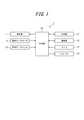
図1は、第1の実施形態に係る電子機器の概略構成を示すブロック図である。図1に示す例では、電子機器1は、表示部11と、表面タッチセンサ12と、背面タッチセンサ13と、制御部14と、記憶部15と、通信部16と、マイク17と、スピーカ18とを備える。[First Embodiment]
FIG. 1 is a block diagram illustrating a schematic configuration of the electronic apparatus according to the first embodiment. In the example illustrated in FIG. 1, the electronic device 1 includes a
表示部11は、文字、写真、操作用オブジェクト等の画像を表示する。表示部11は、液晶パネル(LCD:Liquid Crystal Display)や有機ELパネル(OELD:Organic Electroluminescence Display)等を用いて構成される。例えばホーム画面では、表示部11は、電話、メール、インターネット通信、カメラ撮影等の各操作を行うための操作用オブジェクトを表示させる。 The
表面タッチセンサ12は、表面タッチセンサ12の入力面において、指の接触または接触の解除を検出する。そして、表面タッチセンサ12は、入力面に対する接触位置を検出し、検出した接触位置を示す信号を制御部14へ出力する。表面タッチセンサ12は透明な部材で構成され、表示部11の前面に重畳配置される。ユーザは透明の表面タッチセンサ12を介して表示部11の画像を視認し、表示部11が表示する操作用オブジェクトの表示位置の表面タッチセンサ12を操作することにより、電子機器1に所定の処理を実行させる。ここで、タッチセンサの操作とは、タッチ、タップ、ダブルタップ、フリック等の、指をタッチセンサに接触させるあらゆる操作をいう。 The
背面タッチセンサ13は、片手で電子機器1を操作する際の操作性を向上させるために電子機器1の背面に配置され、背面タッチセンサ13の入力面において、指による接触または接触の解除を検出し、検出結果を制御部14へ出力する。表面タッチセンサ12および背面タッチセンサ13は、例えば、抵抗膜方式、静電容量方式等の周知の方式で実現される。 The
制御部14は、表面タッチセンサ12から入力される信号により表面タッチセンサ12の操作を検出すると、接触位置に表示されている操作用オブジェクトに応じた制御を行う。 When the operation of the
また、制御部14は、背面タッチセンサ13から入力される信号により背面タッチセンサ13の操作を検出すると、表面タッチセンサ12の操作を検出しなくても、表示部11に表示中の画像に対して所定の処理を行う。例えば、制御部14は背面タッチセンサ13の操作を検出すると、画像の選択を行ったり、表示中の画面を閉じたりする処理を行う。 Further, when the
記憶部15は、半導体メモリ等で構成することができ、各種情報や電子機器1を動作させるためのプログラム等を記憶するとともに、ワークメモリとしても機能する。 The
通信部16は、基地局または他の通信機器と無線により通信することを可能にする。 The
マイク17は、ユーザの発話等の周囲の音を集音する。マイク17が集音した音は、電気信号に変換して制御部14に送られる。 The microphone 17 collects ambient sounds such as a user's utterance. The sound collected by the
スピーカ18は、音声、音楽、着信音等の音を出力する。 The
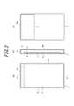
図2は、第1の実施形態に係る電子機器1の実装構造の一例を示す図である。図2(a)は正面図であり、図2(b)は図2(a)におけるA−A線に沿った断面図であり、図2(c)は背面図である。 FIG. 2 is a diagram illustrating an example of a mounting structure of the electronic device 1 according to the first embodiment. 2A is a front view, FIG. 2B is a cross-sectional view taken along the line AA in FIG. 2A, and FIG. 2C is a rear view.
なお、図2においては、筐体10、表示部11、表面タッチセンサ12、背面タッチセンサ13、および接合部材40以外の要素の図示は省略している。電子機器1は、図2に示した以外にも、例えば、制御部14、基板、及び各種部品等の要素を備えることができる。また、典型的にはマイク17は表面タッチセンサ12の下部に配置され、スピーカ18は表面タッチセンサ12の上部に配置される。 In FIG. 2, illustration of elements other than the
図2に示すように、表面タッチセンサ12は筐体10(例えば、金属や樹脂のケース)の表面10aに配置され、筐体10に支持される。 As shown in FIG. 2, the
表示部11は、筐体10の内部に配置される。例えば、表示部11を表面タッチセンサ12の裏面に接着してもよいし、筐体10の内部に直接固定するか、筐体10の内部配置される基板または表示部用ホルダ等に固定してもよい。図2では、表示部11は、接合部材40を介して表面タッチセンサ12に接着されている。図2(b)に示すように、表示部11を、表面タッチセンサ12の裏面側に配置すれば、表面タッチセンサ12および表示部11によりタッチパネルを構成する際に、表示部11に自由なユーザインタフェースを表示して、ユーザの操作を表面タッチセンサ12により検出することができる。なお、接合部材40は、熱硬化性あるいは紫外線硬化性等を有する接着剤や両面テープ等であり、例えば無色透明のアクリル系紫外線硬化型接着剤である光学弾性樹脂でもよい。 The
背面タッチセンサ13は、電子機器1を片手で保持した際に、人差し指で接触可能な範囲を含むように、筐体10の背面10bに配置され、筐体10に支持される。例えば、図2(b)(c)に示すように、背面タッチセンサ13は筐体10の背面10bの上部に配置される。 The back
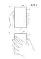
図3は、ユーザが電子機器1を左手で保持した状態を示す図である。図3(a)は表面側から見た図であり、図3(b)は背面側から見た図である。図3(b)に示すように電子機器1を左手で保持すると、人差し指は背面タッチセンサ13上に位置する。よって、ユーザは人差し指を折り曲げるだけで他の指は動かすことなく容易に背面タッチセンサ13を操作(タッチ、タップ、ダブルタップ、フリック等)することができる。なお、本実施形態では、背面タッチセンサ13を人差し指が接触可能な位置に限定して配置しているが、より広範囲にわたって配置させてもよい。 FIG. 3 is a diagram illustrating a state in which the user holds the electronic device 1 with the left hand. 3A is a view seen from the front side, and FIG. 3B is a view seen from the back side. When the electronic device 1 is held with the left hand as shown in FIG. 3B, the index finger is positioned on the
次に、本発明に係る電子機器1による処理を説明する。図4は、第1の実施形態に係る電子機器1の処理を示すフローチャートである。 Next, processing by the electronic apparatus 1 according to the present invention will be described. FIG. 4 is a flowchart illustrating processing of the electronic device 1 according to the first embodiment.
制御部14は、表面タッチセンサ12から入力される信号により表面タッチセンサ12の所定の操作を検出すると(ステップS101−Yes)、接触位置に表示されている操作用オブジェクトに応じた制御を行う(ステップS102)。例えば、制御部14は、表示部11がインターネット接続を開始させるためのブラウザアイコンを表示している場合に、表面タッチセンサ12によりブラウザアイコンの表示位置におけるタップを検出すると、通信部16によりインターネット接続を開始させ、所定のURLにアクセスし、取得したサイト画面を表示部11に表示させる。ステップS102による処理が、電子機器1のブラウザを終了させる処理であった場合には(ステップS103−Yes)、制御部14は、処理を終了して、例えば表示部11にホーム画面(待ち受け画面)を表示させる。 When the
また、制御部14は、背面タッチセンサ13から入力される信号により背面タッチセンサ13の所定の操作を検出すると(ステップS104−Yes)、表面タッチセンサ12に対する操作を検出しなくても、表示部11に表示中の画像に対して所定の処理を行う(ステップS105)。ステップS105の所定の処理の具体例について、以下に説明する。 Moreover, if the
図5は、背面タッチセンサ13の操作により行う処理を説明する図である。なお、この図では、複数の画面(画像)を切り替えて表示可能とするためのアイコンとしてタブオブジェクトを採用しているが、かかるアイコンはタブオブジェクトに限定されるものではない。 FIG. 5 is a diagram for explaining processing performed by operating the back
電子機器1は、表示部11において複数の画面(画像)を切り替え表示することが可能である。例えばインターネットに接続して、あるサイトの画面を表示させた後、リンクページにアクセスする等して新たなサイト画面を表示させる場合、制御部14は表示部11に複数の画面を切り替えて表示させることができる。図5(a)に示す例では、3つの画面が擬似的に重ねて表示されており、複数の画面(画像)を切り替えて表示可能とするためのアイコンとしてタブ111,112,113が表示されている。ユーザは、表面タッチセンサ12上で、タブ111,112,113の表示位置をタップしていずれかのタブを選択することにより、それぞれの画面を切り替えることができる。制御部14は、表面タッチセンサ12上でタブ112の表示位置がタップされことを検出すると、図5(b)に示すように、タブ112に紐付けられた画面を表示部11に表示させる。 The electronic device 1 can switch and display a plurality of screens (images) on the
このようにして、ユーザは表面タッチセンサ12を操作することにより、タブを選択して複数の画面を切り替えることができる。しかし、タブは表示部11の上部に表示されるため、ユーザが片手で操作する際には親指が届かないことがある。そこで、本発明に係る電子機器1では、背面タッチセンサ13を操作することによっても、タブを選択し、切り替え表示可能な複数の画面のうち1つを表示させることを可能とする。例えば、表示部11が図5(a)に示す画像を表示している場合、ユーザは電子機器1を保持する手の人差し指で背面タッチセンサ13をタップすることにより、タブ112、タブ113、タブ111、タブ112・・・と表示されているタブを巡回的に選択して画面を切り替えることができるようにする。つまり、制御部14は、背面タッチセンサ13の第1の操作を検出すると、切り替え表示可能な複数の画面のうち1つを選択して表示させる。 In this manner, the user can select a tab and switch between a plurality of screens by operating the
また、ユーザは選択表示されている画面をクローズするための画面クローズ用アイコン(例えば、選択されているタブの右端に表示される×印)をタップすることにより、表示中の画面を閉じることができる。例えば、表示部11が図5(b)に示す画像を表示している場合、ユーザはタブ112の画面クローズ用アイコンをタップすることにより、図5(c)に示すように、表示中の画面(タブ112に紐付けられている画面)を閉じることができる。つまり、制御部14は、表面タッチセンサ12上でタブ112の画面クローズ用アイコンの表示位置がタップされことを検出すると、表示部11に表示中の画面をクローズさせ、タブ111,113に紐付けられた画面を擬似的に重ねて表示部11に表示させる。 In addition, the user can close the currently displayed screen by tapping a screen closing icon for closing the currently displayed screen (for example, a cross mark displayed at the right end of the selected tab). it can. For example, when the
このようにして、ユーザは表面タッチセンサ12を操作することにより、表示部11に表示中の画面を閉じることができる。しかし、画面クローズ用アイコンは表示部11の上部に表示されるため、ユーザが片手で操作する際には親指が届かないことがある。そこで、本発明に係る電子機器1では、背面タッチセンサ13を操作することによっても画面のクローズを可能とする。例えば、表示部11が図5(b)に示す画像を表示している場合、ユーザは電子機器1を保持する手の人差し指で背面タッチセンサ13をダブルタップすることにより、選択されているタブ112に紐付けられた、表示中の画像を閉じることができるようにする。つまり、制御部14は、背面タッチセンサ13の第2の操作を検出すると、表示部11に表示中の画面(画像)をクローズさせる。 In this way, the user can close the screen being displayed on the
上述したように、第1の実施形態に係る電子機器1は、背面タッチセンサ13の操作を検出すると、制御部14は切り替え表示可能な複数の画面(画像)のうち1つを選択して表示部11に表示させたり、表示部11に表示中の画面をクローズさせたりする、といった表示部11に表示中の画像に対する処理を行う。このため、電子機器1によれば、片手で電子機器を操作する際の操作性を向上させることが可能となる。 As described above, when the electronic device 1 according to the first embodiment detects an operation of the back
[第2の実施形態]
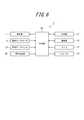
次に、本発明の第2の実施形態について説明する。図6は、本発明の第2の実施形態に係る電子機器の概略構成を示すブロック図である。第2の実施形態に係る電子機器2は、第1の実施形態に係る電子機器1と比較して、更に押圧検出部20を備える。その他の構成については第1の実施形態と同一であるため、同一の参照番号を付して説明を省略する。[Second Embodiment]
Next, a second embodiment of the present invention will be described. FIG. 6 is a block diagram showing a schematic configuration of an electronic apparatus according to the second embodiment of the present invention. The
押圧検出部20は、背面タッチセンサ13に対してユーザが操作を行う際の押圧を検出し、押圧に基づくデータを制御部14に出力する。押圧検出部20は、例えば、押圧に応じて物理的または電気的な特性(歪み、抵抗、電圧等)が変化する歪みゲージセンサや圧電素子等を用いて構成される。押圧検出部20が、例えば圧電素子を用いて構成された場合、押圧検出部20の圧電素子は、背面タッチセンサ13に対する押圧による荷重(力)の大きさ(または、荷重の大きさが変化する速さ(加速度))に応じて、電気的な特性である電圧値(押圧に基づくデータ)が変化する。なお、押圧に基づくデータは、電圧値の代わりに、押圧による荷重の大きさ、電力値、抵抗値等でもよい。 The
また、押圧検出部20は、表面タッチセンサ12に対してユーザが操作を行う際の押圧を同様にして検出してもよい。 Moreover, the
制御部14は、押圧検出部20から背面タッチセンサ13(および表面タッチセンサ12)に対する押圧に基づくデータを取得する。そして、制御部14は、押圧に基づくデータが所定の閾値以上である場合に、所定の操作が行われたと判断し、操作内容に応じて例えばアプリケーションに基づく等して、所定の処理を行うように制御する。 The
また、押圧検出部20は、接触検出方式に応じて構成することができる。例えば、接触検出方式が抵抗膜方式の場合には、接触面積の大きさに応じた抵抗の大きさを、タッチセンサのタッチ面に対する押圧の荷重に対応付けることにより、歪みゲージセンサや圧電素子等を用いることなく押圧検出部20を構成することができる。あるいは、タッチセンサが静電容量方式の場合には、静電容量の大きさを、タッチセンサに対する押圧の荷重に対応付けることにより、歪みゲージセンサや圧電素子等を用いることなく構成することができる。 Moreover, the
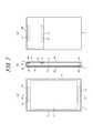
図7は、第2の実施形態に係る電子機器2の実装構造の一例を示す図である。図7(a)は正面図であり、図7(b)は図7(a)におけるA−A線に沿った断面図であり、図7(c)は背面図である。図7は、図2に示した電子機器1の実装構造に対して、更に押圧検出部20を構成する圧電素子21〜24を図示している。なお、圧電素子の個数や配置位置は、図示した例に限定されるものではない。 FIG. 7 is a diagram illustrating an example of a mounting structure of the
図7に示す例では、押圧検出部20は、第1圧電素子21、第2圧電素子22、第3圧電素子23、および第4圧電素子24を有し、第1圧電素子21および第2圧電素子22により、背面タッチセンサ13に対してユーザが操作を行う際の押圧を検出し、第3圧電素子23および第4圧電素子24により、表面タッチセンサ12に対してユーザが操作を行う際の押圧を検出する。 In the example illustrated in FIG. 7, the
なお、図7(a)において、表面タッチセンサ12上において表示部11による表示を透過させる必要がない領域、すなわち、表面タッチセンサ12と表示部11とが重ならない領域は、表面タッチセンサ12の端辺付近の領域を塗装したりベゼルで覆ったりするのが好適である。このようにすれば、第3圧電素子23および第4圧電素子24等が電子機器1の外部から見えてしまうことを防ぐことができる。 In FIG. 7A, the area on the
次に、本発明に係る電子機器2による処理を説明する。図8は、第2の実施形態に係る電子機器2の処理を示すフローチャートである。 Next, processing by the
制御部14は、表面タッチセンサ12から入力される信号により表面タッチセンサ12の所定の操作を検出すると(ステップS201−Yes)、押圧検出部20から表面タッチセンサ12に対する押圧に基づくデータを取得する(ステップS202)。そして、制御部14は、取得した押圧に基づくデータが所定の閾値を満たしたか否かを判定し(ステップS203)、押圧に基づくデータが所定の閾値を満たした場合に(ステップS203−Yes)、表面タッチセンサ12の押圧操作が行われたと判断し、押圧位置に表示されている操作用オブジェクトに応じた制御を行う(ステップS204)。ここで、押圧に基づくデータが所定の閾値を満たした際とは、押圧に基づくデータが所定の基準値に達した際であってもよいし、押圧に基づくデータが所定の基準値を超えた際でもよいし、所定の基準値と等しい押圧に基づくデータが検出された際でもよい。ステップS204による処理が、アプリケーションやメニュー等を終了させる処理であった場合には(ステップS205−Yes)、処理を終了して、例えば表示部11にホーム画面(待ち受け画面)を表示させる。 When the
また、制御部14は、背面タッチセンサ13から入力される信号により背面タッチセンサ13の所定の操作を検出すると(ステップS206−Yes)、押圧検出部20から背面タッチセンサ13に対する押圧に基づくデータを取得する(ステップS207)。そして、制御部14は、取得した押圧に基づくデータが所定の閾値を満たしたか否かを判定し(ステップS208)、押圧に基づくデータが所定の閾値以上を満たした場合に(ステップS208−Yes)、背面タッチセンサ13の操作が行われたと判断し、表面タッチセンサ12に対する操作を検出しなくても、表示部11に表示中の画面(画像)やオブジェクトに対して所定の処理を行う(ステップS209)。所定の処理については、第1の実施形態で説明した通りである。 Moreover, if the
上述したように、第2の実施形態に係る電子機器2は、押圧検出部20を更に備え、制御部14は、押圧に基づくデータが所定の閾値を満たした場合に、表示中の画面(画像)やオブジェクトに対して所定の処理を行う。そのため、電子機器2は、他の物体と軽く接触しただけでユーザによる操作が行われたと判断することを防止できる。特に、電子機器を保持する際には背面に指が接触するが、押圧検出部20により押圧を検出することにより、ユーザが操作を意図していないのにもかかわらず操作したものと誤判断することを防止できる。 As described above, the
[第3の実施形態]
次に、本発明の第3の実施形態について説明する。図9は、本発明の第3の実施形態に係る電子機器の概略構成を示すブロック図である。第3の実施形態に係る電子機器3は、第2の実施形態に係る電子機器2と比較して、更に触感呈示部30を備える。その他の構成については第2の実施形態と同一であるため、同一の参照番号を付して説明を省略する。[Third Embodiment]
Next, a third embodiment of the present invention will be described. FIG. 9 is a block diagram showing a schematic configuration of an electronic apparatus according to the third embodiment of the present invention. The electronic device 3 according to the third embodiment further includes a tactile
触感呈示部30は、制御部14から供給される駆動信号に基づいて所定の振動を発生する。駆動信号については、表現したいリアルなボタンが挙動する振動を、指が接触する位置において表現する駆動信号であればよい。 The tactile
触感呈示部30は、圧電素子、超音波振動子、または振動モータ(偏心モータ)等を用いて構成され、所定の振動パターンによる振動を発生させることにより、背面タッチセンサ13を押圧しているユーザの指に対して触感を呈示し、ユーザに背面タッチセンサ13を操作したことを感覚的に通知する。触感呈示部30は、機械的な振動を使わずに、背面タッチセンサ13上に貼ったフィルムの電荷を制御する等により、背面タッチセンサ13を押圧しているユーザの指に対して触感を呈示してもよい。 The tactile
また、触感呈示部30は、表面タッチセンサ12に対しても、同様にして振動を発生させて、表面タッチセンサ12を押圧しているユーザの指に対して触感を呈示するようにしてもよい。 Further, the tactile
なお、触感呈示部30は、押圧検出部20と一体化して構成することもできる。特に、押圧検出部20および触感呈示部30を圧電素子を用いて構成する場合は、圧電素子を共用することもできる。圧電素子は、圧力が加わると電圧を発生し、電圧が加えられると変形するためである。この場合の実装構造例は、図7に示した通りである。 It should be noted that the tactile
押圧検出部20および触感呈示部30を圧電素子を用いて構成する場合、制御部14は、圧電素子の電圧値が所定の閾値を満たした際に、所定の処理を行うとともに、該圧電素子を駆動することにより振動を発生させるようにしてもよい。ここで、圧電素子の電圧値が所定の閾値を満たした際とは、電圧値が所定の基準値に達した際であってもよいし、電圧値が所定の基準値を超えた際でもよいし、所定の基準値と等しい電圧値が検出された際でもよい。 When the
上述したように、第3の実施形態に係る電子機器3は、触感呈示部30を更に備え、制御部14から供給される駆動信号に基づいて所定の振動を発生する。そのため、電子機器3は、ユーザが背面タッチセンサ13(および表面タッチセンサ12)を操作した際に、意図した操作が行われたことを感覚的にユーザに通知することができる。 As described above, the electronic device 3 according to the third embodiment further includes the tactile
上述の実施形態は代表的な例として説明したが、本発明の趣旨及び範囲内で、多くの変更及び置換ができることは当業者に明らかである。したがって、本発明は、上述の実施形態によって制限するものと解するべきではなく、特許請求の範囲から逸脱することなく、種々の変形や変更が可能である。例えば、実施形態に記載の複数の構成ブロックを1つに組み合わせたり、あるいは1つの構成ブロックを分割したりすることが可能である。 Although the above embodiment has been described as a representative example, it will be apparent to those skilled in the art that many changes and substitutions can be made within the spirit and scope of the invention. Therefore, the present invention should not be construed as being limited by the above-described embodiments, and various modifications and changes can be made without departing from the scope of the claims. For example, a plurality of constituent blocks described in the embodiments can be combined into one, or one constituent block can be divided.
1,2,3 電子機器
11 表示部
12 表面タッチセンサ
13 背面タッチセンサ
14 制御部
15 記憶部
16 通信部
17 マイク
18 スピーカ
20 押圧検出部
21 第1圧電素子
22 第2圧電素子
23 第3圧電素子
24 第4圧電素子
30 触感呈示部
40 接合部材1, 2, 3
Claims (4)
Translated fromJapanese背面のタッチセンサの操作を検出すると、表示中の画面をクローズさせる制御部
を備えることを特徴とする電子機器。An electronic device having touch sensors on the front and back surfaces,
An electronic apparatus comprising: a control unit that closes a displayed screen when an operation of a touch sensor on a back surface is detected.
前記背面のタッチセンサに対する押圧を検出する押圧検出部と、
前記押圧検出部により検出される押圧に基づくデータが所定の基準を満たすと、表示中の画面をクローズさせる制御部と、
を備えることを特徴とする電子機器。An electronic device having touch sensors on the front and back surfaces,
A pressure detector for detecting pressure on the touch sensor on the back surface;
When the data based on the pressure detected by the pressure detection unit satisfies a predetermined standard, a control unit that closes the displayed screen;
An electronic device comprising:
Applications Claiming Priority (3)
| Application Number | Priority Date | Filing Date | Title |
|---|---|---|---|
| JP2013223539 | 2013-10-28 | ||
| JP2013223539 | 2013-10-28 | ||
| PCT/JP2014/004943WO2015064008A1 (en) | 2013-10-28 | 2014-09-26 | Electronic device |
Publications (1)
| Publication Number | Publication Date |
|---|---|
| JPWO2015064008A1true JPWO2015064008A1 (en) | 2017-03-09 |
Family
ID=53003644
Family Applications (1)
| Application Number | Title | Priority Date | Filing Date |
|---|---|---|---|
| JP2015544774APendingJPWO2015064008A1 (en) | 2013-10-28 | 2014-09-26 | Electronics |
Country Status (3)
| Country | Link |
|---|---|
| US (1) | US10996712B2 (en) |
| JP (1) | JPWO2015064008A1 (en) |
| WO (1) | WO2015064008A1 (en) |
Families Citing this family (3)
| Publication number | Priority date | Publication date | Assignee | Title |
|---|---|---|---|---|
| JP5197521B2 (en)* | 2009-07-29 | 2013-05-15 | 京セラ株式会社 | Input device |
| BR112023024637A2 (en) | 2021-05-27 | 2024-02-06 | Ericsson Telefon Ab L M | REAR USER INTERFACE FOR PORTABLE DEVICE |
| US11861084B2 (en)* | 2021-11-18 | 2024-01-02 | International Business Machines Corporation | Splitting a mobile device display and mapping content with single hand |
Citations (3)
| Publication number | Priority date | Publication date | Assignee | Title |
|---|---|---|---|---|
| WO2012108203A1 (en)* | 2011-02-10 | 2012-08-16 | 京セラ株式会社 | Electronic device and method of controlling same |
| JP2013142907A (en)* | 2012-01-06 | 2013-07-22 | Canon Inc | Input device and method for controlling input device |
| JP2013200882A (en)* | 2013-05-16 | 2013-10-03 | Sony Computer Entertainment Inc | Information processing apparatus |
Family Cites Families (6)
| Publication number | Priority date | Publication date | Assignee | Title |
|---|---|---|---|---|
| US7966573B2 (en)* | 2006-02-17 | 2011-06-21 | Microsoft Corporation | Method and system for improving interaction with a user interface |
| JP5528542B2 (en)* | 2010-04-09 | 2014-06-25 | 株式会社ソニー・コンピュータエンタテインメント | Information processing device |
| CN103167807B (en)* | 2010-08-26 | 2015-11-25 | 陶氏环球技术有限责任公司 | Strengthen the method for the storage stability of probio |
| JP5661547B2 (en) | 2011-04-26 | 2015-01-28 | 京セラ株式会社 | Portable terminal device and program |
| US8775966B2 (en)* | 2011-06-29 | 2014-07-08 | Motorola Mobility Llc | Electronic device and method with dual mode rear TouchPad |
| US9417754B2 (en)* | 2011-08-05 | 2016-08-16 | P4tents1, LLC | User interface system, method, and computer program product |
- 2014
- 2014-09-26JPJP2015544774Apatent/JPWO2015064008A1/enactivePending
- 2014-09-26USUS15/031,820patent/US10996712B2/enactiveActive
- 2014-09-26WOPCT/JP2014/004943patent/WO2015064008A1/enactiveApplication Filing
Patent Citations (3)
| Publication number | Priority date | Publication date | Assignee | Title |
|---|---|---|---|---|
| WO2012108203A1 (en)* | 2011-02-10 | 2012-08-16 | 京セラ株式会社 | Electronic device and method of controlling same |
| JP2013142907A (en)* | 2012-01-06 | 2013-07-22 | Canon Inc | Input device and method for controlling input device |
| JP2013200882A (en)* | 2013-05-16 | 2013-10-03 | Sony Computer Entertainment Inc | Information processing apparatus |
Also Published As
| Publication number | Publication date |
|---|---|
| WO2015064008A1 (en) | 2015-05-07 |
| US10996712B2 (en) | 2021-05-04 |
| US20160246437A1 (en) | 2016-08-25 |
Similar Documents
| Publication | Publication Date | Title |
|---|---|---|
| WO2015079688A1 (en) | Electronic instrument | |
| JP6246640B2 (en) | Electronics | |
| US10353567B2 (en) | Electronic device | |
| WO2011024461A1 (en) | Input device | |
| JP5519020B2 (en) | Input device and control method of input device | |
| JP5718475B2 (en) | Tactile presentation device | |
| WO2015064008A1 (en) | Electronic device | |
| WO2015098061A1 (en) | Electronic instrument | |
| JP6356411B2 (en) | Electronics | |
| WO2015079687A1 (en) | Electronic device | |
| JP6530160B2 (en) | Electronics | |
| JP6367547B2 (en) | Electronics | |
| JP6062351B2 (en) | Electronics | |
| JP2015121996A (en) | Electronics | |
| JP6348948B2 (en) | Electronics | |
| JP6069117B2 (en) | Electronic device, control program, and operation method | |
| JP2015106734A (en) | Electronic apparatus |
Legal Events
| Date | Code | Title | Description |
|---|---|---|---|
| A02 | Decision of refusal | Free format text:JAPANESE INTERMEDIATE CODE: A02 Effective date:20170214 |