JPWO2015037156A1 - Container cap structure - Google Patents
Container cap structureDownload PDFInfo
- Publication number
- JPWO2015037156A1 JPWO2015037156A1JP2015536419AJP2015536419AJPWO2015037156A1JP WO2015037156 A1JPWO2015037156 A1JP WO2015037156A1JP 2015536419 AJP2015536419 AJP 2015536419AJP 2015536419 AJP2015536419 AJP 2015536419AJP WO2015037156 A1JPWO2015037156 A1JP WO2015037156A1
- Authority
- JP
- Japan
- Prior art keywords
- pressing
- peripheral wall
- cap
- annular peripheral
- container
- Prior art date
- Legal status (The legal status is an assumption and is not a legal conclusion. Google has not performed a legal analysis and makes no representation as to the accuracy of the status listed.)
- Pending
Links
Images


Classifications
- B—PERFORMING OPERATIONS; TRANSPORTING
- B65—CONVEYING; PACKING; STORING; HANDLING THIN OR FILAMENTARY MATERIAL
- B65D—CONTAINERS FOR STORAGE OR TRANSPORT OF ARTICLES OR MATERIALS, e.g. BAGS, BARRELS, BOTTLES, BOXES, CANS, CARTONS, CRATES, DRUMS, JARS, TANKS, HOPPERS, FORWARDING CONTAINERS; ACCESSORIES, CLOSURES, OR FITTINGS THEREFOR; PACKAGING ELEMENTS; PACKAGES
- B65D51/00—Closures not otherwise provided for
- B65D51/002—Closures to be pierced by an extracting-device for the contents and fixed on the container by separate retaining means
Landscapes
- Engineering & Computer Science (AREA)
- Mechanical Engineering (AREA)
- Closures For Containers (AREA)
- Medical Preparation Storing Or Oral Administration Devices (AREA)
Abstract
Translated fromJapaneseDescription
Translated fromJapanese本発明は、注射用薬液等の液体を収納した容器をゴム栓等のシール材で密封し、その開口部とシール材とをキャップで覆うようにした容器のキャップ構造の改良に関する。 The present invention relates to an improvement in the cap structure of a container in which a container containing a liquid such as an injectable drug solution is sealed with a sealing material such as a rubber stopper and the opening and the sealing material are covered with a cap.
従来、バイアル瓶等のキャップとして、例えば、特開平6−312758号の容器の蓋構造では、キャップの上面部に加えられる所定以上の力で切断される一連の環状の薄肉部を形成し、その環状の薄肉部の位置より内側に上面部に対してほぼ直角方向に突出する突出筒部とその突出筒部の先端を覆う押圧用上面部とをその上面部に一体に形成し、その押圧用上面部を密閉栓側に押すことによって前記薄肉部を切断してその切断した薄肉部の内側に位置する部材をキャップから分離し、押圧用上面部を押す力を除いた際に前記キャップから分離した部材を前記弾力性のある密閉栓の突出腕によって密閉栓とは反対方向に反発移動するようにした構造が開示されている。
しかし、上記構成では、円盤部の破断面が突起部破断面とほぼ平行にセリ合う形態で離脱する為に抵抗が大きく離脱ができなかった。
一方、特公平4−76871号の容器用蓋では、作業者が指先に切り傷を負わないように、薄肉部は突出部を折り取った時に裂断された折り口が返りバリを生じないように形成される構成が開示されている。
しかし、上記構成では、突出部を横から押し倒す方法であって、突出部を長くする必要が有り、嵩張るため梱包形態が大きくなる、という不具合がある。
そこで、本出願人は、特許第4902820号で、キャップ上壁面にシール部材の上面に接して形成される切り離し用の円板部と、該円板部の外周縁となる切り離しガイド用の薄肉部と、前記円板部と一体に突設されて切り離し時に押し付けるための突起部とからなる容器のキャップ構造において、円板部ないし突起部の底部で、突起部の軸線から径方向に離間した位置に下方に突出する1又は複数の突部を設け、該突部はシール部材を反発可能に押し込んだ状態でシール部材上に取り付け密閉したキャップを指で簡単に切り離しシール部材上から取り除くことができるようにして、相応の成果をあげている。
本出願人は、更に鋭意研究を行い、金属製のキャップに着色した樹脂製の押圧部を組み合わせて識別を容易にすると共に、切離された部分の一部がキャップの開口縁部の下に潜り込んで引っ掛かることがなく、確実にキャップから分離させ取り除くことができる構造を創案するに至った。Conventionally, as a cap of a vial or the like, for example, in the container lid structure of JP-A-6-31758, a series of thin annular portions that are cut by a force more than a predetermined force applied to the upper surface of the cap are formed. A projecting cylinder part projecting in a direction substantially perpendicular to the upper surface part from the position of the annular thin part and an upper surface part for pressing covering the tip of the projecting cylinder part are integrally formed on the upper surface part, and the pressing When the upper surface portion is pushed toward the sealing plug, the thin portion is cut and the member located inside the cut thin portion is separated from the cap, and separated from the cap when the force pushing the upper surface portion for pressing is removed. A structure is disclosed in which the member is repelled and moved in the direction opposite to the sealing plug by the projecting arm of the elastic sealing plug.
However, in the above configuration, since the fracture surface of the disk part is separated in a form that is substantially parallel to the protrusion fracture surface, the resistance is large and the separation cannot be performed.
On the other hand, in the container lid of Japanese Examined Patent Publication No. 4-76871, so that the thin-walled portion is broken when the protruding portion is broken, the fold opening is not returned and the burr is not generated so that the operator does not cut the fingertip. The structure to be formed is disclosed.
However, the above-described configuration is a method of pushing down the protruding portion from the side, and it is necessary to lengthen the protruding portion.
In view of this, the present applicant has disclosed in Japanese Patent No. 4902820 a separation disk part formed on the upper wall surface of the cap in contact with the upper surface of the sealing member, and a separation guide thin part serving as the outer peripheral edge of the disk part. And a protruding portion integrally formed with the disc portion and a projection portion for pressing when separated, a position spaced radially from the axis of the projection portion at the disc portion or the bottom portion of the projection portion One or a plurality of protrusions projecting downward are provided on the seal member, and the protrusion can be easily detached with a finger and removed from the seal member after the cap is attached and sealed on the seal member in a state where the seal member is pushed in a repulsive manner. In this way, it has achieved reasonable results.
The Applicant has conducted further research and combined a colored resin pressing part on a metal cap to facilitate identification, and a part of the separated part is below the opening edge of the cap. The inventors have come up with a structure that can be securely separated and removed from the cap without being caught and caught.
この発明の解決しようとする課題は、金属製のキャップの上部に着色した樹脂製の押圧部を組み合わせて切離し用突起部を形成して、容器の識別を容易にすると共に、前記切離し用突起部の外周縁下部に沿って切り離しガイド用の薄肉部を形成し、前記樹脂製の押圧部に下向きに突出する突部を設けることで、容器の識別を樹脂製の押圧部の着色により確実に行うことができると共に、切離し用突起部をキャップから切離した際に、離し用突起部の外周壁の下部に外方へ突出するフランジ部分を形成させることなく、指で容易に且つ確実に切離し用突起部をシール部材上から取り除くことができるバイアル等の容器のキャップ構造を提供することにある。 The problem to be solved by the present invention is to form a separation protrusion by combining a colored resin pressing portion on the upper part of a metal cap to facilitate identification of the container, and the separation protrusion. A thin guide portion is formed along the lower peripheral edge of the container, and a protrusion projecting downward is provided on the resin-made pressing portion, whereby the container is reliably identified by coloring the resin-made pressing portion. When the separation protrusion is separated from the cap, the separation protrusion can be easily and reliably formed with a finger without forming a flange portion protruding outward at the lower portion of the outer peripheral wall of the separation protrusion. It is an object of the present invention to provide a cap structure for a container such as a vial that can be removed from the seal member.
この発明は、容器の開口部を密封した弾性を有するシール部材と、該シール部材を覆って開口部に外嵌されるキャップと、該キャップの上壁面で前記シール部材の上面に対応する個所に切離し用の環状の薄肉部を介して一体に形成される切離し用突起部とを設けたバイアル等の容器のキャップ構造において、
キャップが、キャップ上壁面の一部で上向きに突設されて上面が開口した中空の環状周壁部を設けた金属製のキャップ本体と、
前記環状周壁部の上端の衝合面に、押圧面を有する押圧面部の裏面が衝合すると共に、押圧本体部が環状周壁部の中空内に固定され、該押圧本体部の下方にシール部材の弾性力に抗してシール部材を押圧する下方突部を有し、少なくとも押圧面部が所定の色に着色された合成樹脂製の押圧部とからなり、
前記環状周壁部の外周壁の基部に沿って環状の薄肉部が形成されていることを特徴とする。According to the present invention, an elastic seal member that seals the opening of the container, a cap that covers the seal member and is fitted onto the opening, and a portion corresponding to the upper surface of the seal member on the upper wall surface of the cap In a cap structure of a container such as a vial provided with a separation projection formed integrally through an annular thin portion for separation,
A cap body made of metal provided with a hollow annular peripheral wall portion projecting upward at a part of the upper wall surface of the cap and having an upper surface opened;
The back surface of the pressing surface portion having a pressing surface abuts with the abutting surface at the upper end of the annular peripheral wall portion, the pressing main body portion is fixed in the hollow of the annular peripheral wall portion, and a seal member is disposed below the pressing main body portion. It has a lower protrusion that presses the seal member against the elastic force, and at least the pressing surface portion is made of a synthetic resin pressing portion colored in a predetermined color,
An annular thin portion is formed along a base portion of the outer peripheral wall of the annular peripheral wall portion.
本発明では、切離し用突起部が、金属製のキャップ本体に一体形成された環状周壁部と、着色された樹脂製の押圧部との組み合わせからなっており、押圧部の底面にシール部材を押圧する下方突部を形成するので、環状周壁部から突出する押圧部の色彩により容器の色分けによる識別が確実にでき、また下方突部はキャップ本体と一体に形成する必要がなく、容器内に内蔵されたシール部材に対応して最適の形状のものを使用することができる。
使用に際しては、指で切離し用突起部を押すことで、下方突部を介して切離し用突起部の外周壁の下部が薄肉部から切断されるので、前記外周壁の下部に外方へ突出するフランジ状の部分を形成させることなく、開口したキャップの口縁部に対して切離し用突起部の外周壁の下部が立ち上がっているので、切離し用突起部の外周壁の下部が前記開口の口縁部の下に入り込む虞れが無い。In the present invention, the separating protrusion is composed of a combination of an annular peripheral wall portion integrally formed with the metal cap body and a colored resin pressing portion, and presses the sealing member against the bottom surface of the pressing portion. Since the lower protrusion is formed, the color of the pressing portion protruding from the annular peripheral wall can be used for reliable identification by color coding of the container, and the lower protrusion does not need to be formed integrally with the cap body and is built in the container. An optimum shape can be used in accordance with the seal member formed.
In use, the lower part of the outer peripheral wall of the separating projection part is cut from the thin wall part by pushing the separating projection part with a finger through the lower projecting part, so that it protrudes outward to the lower part of the outer peripheral wall. Since the lower part of the outer peripheral wall of the separating protrusion is raised with respect to the opening edge of the cap without forming a flange-shaped part, the lower part of the outer peripheral wall of the separating protrusion is the edge of the opening. There is no fear of getting under the part.
この発明は、切離し用突起部が、金属製のキャップ本体に一体形成された環状周壁部と、着色された樹脂製の押圧部との組み合わせからなっているので、容器の色彩による識別を確実に行えると共に、押圧部に下方突部を一体成形するので成形しやすく、切離し用突起部をキャップから確実に切離されることを実現した。
以下に、この発明の容器のキャップ構造をバイアル瓶のキャップ構造に適用した場合の実施例について図面を参照しながら説明する。According to the present invention, the separation protrusion is composed of a combination of an annular peripheral wall portion integrally formed with the metal cap body and a colored resin pressing portion. In addition to being able to do this, the lower protrusion is formed integrally with the pressing portion, so that it is easy to form and the separation protrusion is reliably separated from the cap.
Hereinafter, an embodiment in which the container cap structure of the present invention is applied to a vial cap structure will be described with reference to the drawings.
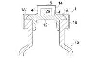
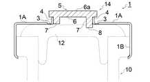
実施例1のキャップ1は、バイアル瓶10の開口部11にゴムやエラストマ等の弾性を有するシール部材12を隙間無く嵌合して密閉した前記バイアル瓶10に冠着されるもので、前記シール部材12の上面を覆って外嵌し固定した構造からなっている(図5参照)。 The
[キャップ]
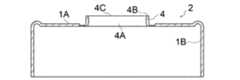
キャップ1は、図1〜4に示すように、前記開口部11を覆う平面視円形状のキャップ上壁面1Aと、キャップ上壁面1Aの外周に沿って垂下し、内面にバイアル瓶10の前記開口部11の外周壁に外嵌し固定される円柱状のキャップ周壁部1Bとからなる金属製のキャップ本体2と、該キャップ本体2のキャップ上壁面1Aと組み合わせて切離し用突起部14を形成する樹脂製の押圧部5とからなっている。[cap]
As shown in FIGS. 1 to 4, the
[切離し用突起部]
切離し用突起部14(図3、図5参照)は、キャップ上壁面1Aの一部で上向きに一体に突設されて上面が開口した環状周壁部4と、該環状周壁部4に嵌合固定される樹脂製の押圧部5とからなっている。[Protrusion for separation]
The separation protrusion 14 (see FIGS. 3 and 5) is fitted and fixed to the annular
[環状周壁部]
前記キャップ上壁面1Aには、その中央ないし中央位置近傍に、略筒形状の環状周壁部4が一体に形成されている。
該環状周壁部4は上面が開口4Cし、そのまま貫通して前記押圧部5を嵌合するための中空部4Aが形成されている。
また、環状周壁部4の上端は、押圧部5の押圧面部6の裏面と衝合して、押圧面6aにかかる
下向きの力をキャップ本体2側に伝える衝合面4Bが形成されている。[Annular peripheral wall]
On the cap
The annular
Further, the upper end of the annular
また、図示例の場合は、環状周壁部4の上端の内周面側は、開口を上方に向かって漸次大径にするテーパー面44にして、押圧部5の挿入を容易にしている。
そして、上記環状周壁部4の開口から押圧部5を中空部4Aに嵌合し、前記上端の衝合面4Bに押圧面部の底面を衝合させており、また押圧部5が環状周壁部4から抜け出ることがないように一体に連結している。Further, in the case of the illustrated example, the inner peripheral surface side of the upper end of the annular
Then, the
押圧部5が環状周壁部4から抜け出ない構成としては、環状周壁部4の内壁面で押圧部の外壁面を挟圧する方法(図2、図4参照)、環状周壁部4の内壁面と押圧部の外壁面の接触する面に凹凸係合する段部を設けて係合させる方法(図8参照)、前記接触面を接着剤などで接着する(蒸着・溶着を含む)方法(図示せず)、固定具で両者を固着する方法(図示せず)などの構成を単独で、あるいは複数を組合わせて用いてもよい。 As a configuration in which the
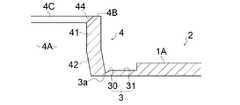
本実施例では、図4に明瞭なように、環状周壁部4は、上部41の内径が押圧部5の押圧本体部7の外径より小さく(径を短く)設定されており、上部41の内壁面と接する押圧本体部7の外壁面を挟圧するようになっている。
また、周壁面の下部42の内径は上部41の内径より長く拡開しており、前記上部41の内壁面を通過した押圧本体部7の下部が収縮状態から弾性復帰して収納しうるようになっているので、本実施例の環状周壁部4は、一種のアリ溝構造となっている。In the present embodiment, as clearly shown in FIG. 4, the annular
Further, the inner diameter of the
これにより、押圧部5を環状周壁部4の開口から強く押し込んで、押圧本体部7を弾性で横幅方向に圧縮して環状周壁部4の中空内に嵌合し、上部41の内壁面により押圧部5の外壁面を挟圧することで、強固に連結することができる。
更に、本実施例では、上部41の内壁面を通過した押圧本体部7の下部は下部42の内壁面により縮小状態から復帰して拡大されるので、押圧本体部7は前記上部41の内壁面による挟圧と下部42による復元とによって緊締することができる。As a result, the
Further, in this embodiment, the lower portion of the
[薄肉部]
前記環状周壁部4は、その基部に切り離しガイド用の薄肉部3が形成されており、該薄肉部3を介してキャップ上壁面1Aと一体に形成されている。
この薄肉部3は、本実施例では、切離し用突起部14の外周壁の下部と接した位置で環状に形成された溝からなっている。
薄肉部3は、環状周壁部4の下部42の外周面に接する個所がキャップ上壁面1Aで肉厚を最も薄くした最薄部3aとなっており、該最薄部3a向かって外方から漸次薄肉となるように断面傾斜状に切り欠かれている。[Thin part]
The annular
In this embodiment, the
The thin-
従って、切離し用突起部14の押圧面6aを下向きに押圧すると、最も脆弱な最薄部3aに亀裂が生じて前記環状周壁部4の下部42と切り離されるので、前記下部42の下端にはフランジやフランジ状に延びるバリなどが形成することがない。
本実施例では、薄肉部3はキャップ上壁面1Aの上面側が窪む溝として形成されているが、底面側が窪む溝、あるいは上面と底面の双方が窪む溝状に形成されるものでもよい。Accordingly, when the
In the present embodiment, the
本実施例で薄肉部3は、キャップ上壁面1Aの厚みより薄肉にした基部薄肉部31と、該基部薄肉部31を介して切離し用突起部14の周壁面の下部42の外周面下端側に向かって漸次薄肉となる薄肉部本体30とからなっており、最も薄肉となって前記外周壁の下部と接する最薄部3aが薄肉部本体30の先端となるように形成されて切り取りが確実に行えるようにしている。
この発明で薄肉部3の構成は、断面V字状やU字状の溝、その他公知の溝形状や、ミシン目のような構造でもよい。In this embodiment, the
In the present invention, the configuration of the
このように構成されているので、キャップ上壁面1Aに形成された薄肉部3に沿って切り離された切離し用突起部14によって開口2(図6参照)が形成されると、薄肉部3によって切り離された環状周壁部4の下端は下向きとなっており、略水平に延びるキャップ上壁面1Aの前記開口2の口縁部とは互いに交差する方向になる。
従って、押圧部5に加わるシール部材12の反発力により上昇する切離し用突起部14の下端縁部が前記開口2の口縁部の下に入り込む虞れがなく、切り離された切離し用突起部14は、支障なくシール部材12上に浮き上がり、容易に取り除くことができる。Since it is configured in this manner, when the opening 2 (see FIG. 6) is formed by the
Therefore, there is no possibility that the lower end edge of the
[押圧部]
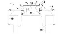
押圧部5は、所定の色に着色された合成樹脂材からなっており、上面に押圧面6aを有し、裏面6bが環状周壁部4の上端の衝合面4Bに掛け止められると共に、押圧力を受けるための厚みと強度を備えた押圧面部7と、該押圧面部7に連接し前記環状周壁部4の中空部4Aに嵌合される押圧本体部7と、該押圧本体部7の下方に設けられて、バイアル瓶10にキャップ1を装着した際に、シール部材12を反発可能に押圧する下方突部8とからなっている。[Pressing part]
The
[押圧面部]
本実施例では、押圧面部6は、その外周が環状周壁部4の外周と一致するように形成されているが、この発明では後述のように、環状周壁部4の外周より大きく形成されるものでもよい。[Pressing surface]
In this embodiment, the
押圧面部6の頂面となる押圧面6aは、図示例では水平面からなっているが、一方に傾く傾斜面、その他の任意の形状としてもよい。
また、素材が合成樹脂であるので、押圧面6aには、梨地、凹凸、波形などの滑り止め用の表面加工を施してもよい。The
Further, since the material is a synthetic resin, the
[押圧本体部]
押圧本体部7は、無垢のブロックでもよいし、図3に示すように中央に空間7aを設けて横方向の弾性を備えた可撓性を高める筒状体であってもよい。
押圧本体部7は、環状周壁部4とほぼ同じ長さからなっており、前述のように環状周壁部4の内壁面によって挟圧される。
押圧本体部7が筒状体の場合、無垢材に比べて強度が低下するので、中空部分に十字状や放射状に掛け渡される補強桟(図示省略)を一体に設けてもよい。
図示例では筒状体の肉厚を厚くすることで強度を保持している。[Pressing body]
The pressing
The pressing
In the case where the pressing
In the illustrated example, the strength is maintained by increasing the thickness of the cylindrical body.
[下方突部]
下方突部8は、押圧本体部7の底部に一体に形成される。
即ち、本実施例では、押圧本体部7は前記押圧本体部材7の環状の周壁部を超えて下方に突出する部分が下方突部8となる。
下方突部8は、本実施例では、押圧本体部7を延長方向に延出して形成されているので、前述のように環状周壁部4を超えて下方に突出する部分が下方突部8となる。[Lower protrusion]
The
That is, in this embodiment, the pressing
In the present embodiment, the
この発明で、下方突部8は、筒状に限らず、筒体を外周方向に沿って隙間を介して複数に分断し、複数の横断面円弧状とした突部形状(後述の図11、12参照)、または半球体(図13参照)などの任意の立体形状などでもよく、バイアル瓶10に嵌着されたシール部材12を反発可能に押圧して、切離された際に、反発力で切離し用突起部14を上向きに押し上げさせるものであればよい。 In the present invention, the
これにより、押圧部5の押圧本体部7を環状周壁部4の中空部4Aに押し込んで一体に連結して切離し用突起部14を形成し、このキャップ1をバイアル瓶10に冠着する(図5参照)。
本実施例では、キャップ1の成形に際して、薄肉部3の位置を押圧面部6の外周よりも外側位置に設定しているので、上記押圧部5を環状周壁部4に装着した後に、加工装置を用いて薄肉部成形個所を下から支持し上から切削して薄肉部3の成形を行うことができる。As a result, the pressing
In the present embodiment, when the
即ち、押圧部5の装着前に、薄肉部3を成形した場合には、成形後に環状周壁部4に押圧部5を押し込むことになるので、押圧部5を押し込む際にかかる荷重で薄肉部3が破断したり亀裂が生じるおそれがあるが、そのような不具合を解消することができる。
本実施例では、環状周壁部4の下部42は、上部41より大きくなるように外向きに拡開したテーパー状となっているので、アリ溝状になると共に、薄肉部3の位置を押圧部5の外周の真下よりも外側に配置することができ、好ましい。That is, when the
In the present embodiment, the
このように完成されたバイアル瓶10は、切離し用突起部14の押圧面6を押し下げることで、環状周壁部4を介して薄肉部3の最薄部3aを破断し、切離し用突起部14をキャップ1のキャップ上壁面1Aから分離することができる(図6参照)。 The completed
分離された切離し用突起部14は、シール部材12の弾性力によってシール部材12上に持ち上げられ、キャップ1から確実に取り外すことでき、キャップ1に開口部11を形成することができる。
また、押圧部5は、全部又は少なくとも押圧面部6を着色しておくことで、バイアル瓶10の充填液を識別するための識別子として用いることができ、金属製のキャップに塗料を塗布した場合に比して、色彩が剥げたり、変色したりすることがない。The separated
Moreover, the
図7〜8に示すキャップ1は、薄肉部3の位置をキャップ上壁面1Aの裏面に形成した異なる実施例である。
即ち、この薄肉部3は、その形成箇所がキャップ上壁面1Aの表面側か裏面側かの相違だけで、薄肉部3の構成は前記実施例と同様であり、キャップ上壁面1Aの厚みより薄肉にした基部薄肉部31と、該基部薄肉部31を介して切離し用突起部14の周壁の下部42の下端側に向かって漸次薄肉となる薄肉部本体30とからなっており、最も薄肉となって前記外周壁の下部と接する最薄部3aが薄肉部本体30の先端となるように形成されている。
この場合も、加工装置を用いて薄肉部成形個所を上から支持し下から切削して薄肉部3の成形を行うことができる。The
That is, the
Also in this case, the
また、本実施例の環状周壁部4は、内壁面に1又は複数の係合段部を設けている。
即ち、環状周壁部4の内壁面には、上端よりやや下方となる上方位置に、内壁面を上端部分より僅かに薄くした第1段部61を形成し、その下方位置に、内壁面を更に僅かに薄くした第2段部62を形成している。Further, the annular
That is, the
押圧部5の押圧本体部7の外周面は平坦面からなっており、押圧部5を環状周壁部4に押し込む際に、前記第1段部61、第2段部62が押圧本体部7に食い込んで、係合力により押圧部5が環状周壁部4によって係止される。
この発明では、押圧本体部7の外周面側にも上記段部61、62に隙間無く係合するように対応した段部を形成しておいてもよい。
このように、本実施例では、係合力またはこれに加えて挟圧力によって押圧部5を環状周壁部4に連結している。
その他の構成は前記実施例1と同様であるので、その説明を省略する。The outer peripheral surface of the
In the present invention, corresponding step portions may be formed on the outer peripheral surface side of the pressing
As described above, in this embodiment, the
Since other configurations are the same as those of the first embodiment, the description thereof is omitted.
図9〜10に示すキャップ1は、押圧部5の押圧面部6の外周を薄肉部3の位置より外側に延出した異なる実施例である。
本実施例では、押圧面部6が大径となり押圧面6aが広く、押圧しやすい形状となっているが、その他の構成は前記実施例と同様であるので、その説明を省略する。The
In the present embodiment, the
この場合、薄肉部3の成形に際しては、真上から加工装置を降ろして薄肉部3を加工することができないが、押圧面部6を避けた下方位置から環状周壁部4を挟むように移動させて薄肉部3を整形することができる。
その他の構成は前記実施例と同様であるので、その説明を省略する。
本実施例で、薄肉部3は実施例2のようにキャップ上壁面1Aの裏面に形成してもよい。In this case, when forming the
Since other configurations are the same as those in the above embodiment, the description thereof is omitted.
In the present embodiment, the
図11〜12に示すキャップ1は、下方突部8の異なる実施例である。
前述のように、下方突部8の形状は問わず、本実施例では、筒体を外周方向に沿って隙間を介して等間隔に3つに分断し、3つの横断面円弧状の突部形状としている。
また、図13に示すように、押圧本体部7を無垢のブロックとし、その底面に先端を球面状とした突部を複数設けたものでもよい。
この発明は上記実施例に限定されるものではなく、その発明の要旨を変更しない範囲で種々設計変更しうる。The
As described above, the shape of the
Further, as shown in FIG. 13, the pressing
The present invention is not limited to the above-described embodiments, and various design changes can be made without changing the gist of the invention.
この発明は、バイアル瓶のキャップに限らず、シール部材で密閉された各種用途の容器のキャップ構造として適用できる。 The present invention is not limited to the cap of a vial bottle, and can be applied as a cap structure of a container for various uses sealed with a seal member.
1 キャップ
1A キャップ上壁面
1B キャップ周壁部
2 キャップ本体
2a 開口
3 薄肉部
3a 最薄部
4 環状周壁部
4A 中空部
4B 衝合面
5 押圧部
6 押圧面部
6a 押圧面
6b 裏面
7 押圧本体部
8 下方突部
10 バイアル瓶
11 開口部
12 シール部材
14 切離し用突起部
30 薄肉部本
31 基部薄肉部
41 周壁面の上部
42 周壁面の下部
61 第1段部
62 第2段部1
2
Claims (8)
Translated fromJapaneseキャップが、キャップ上壁面の一部で上向きに突設されて上面が開口した中空の環状周壁部を設けた金属製のキャップ本体と、
前記環状周壁部の上端の衝合面に、押圧面を有する押圧面部の裏面が衝合すると共に、押圧本体部が環状周壁部の中空内に固定され、該押圧本体部の下方にシール部材の弾性力に抗してシール部材を押圧する下方突部を有し、少なくとも押圧面部が所定の色に着色された合成樹脂製の押圧部とからなり、
前記環状周壁部の外周壁の基部に沿って環状の薄肉部が形成されていることを特徴とする容器のキャップ構造。An elastic seal member that seals the opening of the container, a cap that covers the seal member and is fitted over the opening, and an annular ring that is cut off at a location corresponding to the upper surface of the seal member on the upper wall surface of the cap In the cap structure of a container such as a vial provided with a separating projection formed integrally through the thin-walled portion of
A cap body made of metal provided with a hollow annular peripheral wall portion projecting upward at a part of the upper wall surface of the cap and having an upper surface opened;
The back surface of the pressing surface portion having a pressing surface abuts with the abutting surface at the upper end of the annular peripheral wall portion, the pressing main body portion is fixed in the hollow of the annular peripheral wall portion, and a seal member is disposed below the pressing main body portion. It has a lower protrusion that presses the seal member against the elastic force, and at least the pressing surface portion is made of a synthetic resin pressing portion colored in a predetermined color,
A cap structure for a container, wherein an annular thin portion is formed along a base portion of an outer peripheral wall of the annular peripheral wall portion.
Applications Claiming Priority (1)
| Application Number | Priority Date | Filing Date | Title |
|---|---|---|---|
| PCT/JP2013/074942WO2015037156A1 (en) | 2013-09-13 | 2013-09-13 | Cap structure of container |
Publications (1)
| Publication Number | Publication Date |
|---|---|
| JPWO2015037156A1true JPWO2015037156A1 (en) | 2017-03-02 |
Family
ID=52665296
Family Applications (1)
| Application Number | Title | Priority Date | Filing Date |
|---|---|---|---|
| JP2015536419APendingJPWO2015037156A1 (en) | 2013-09-13 | 2013-09-13 | Container cap structure |
Country Status (2)
| Country | Link |
|---|---|
| JP (1) | JPWO2015037156A1 (en) |
| WO (1) | WO2015037156A1 (en) |
Family Cites Families (5)
| Publication number | Priority date | Publication date | Assignee | Title |
|---|---|---|---|---|
| DE19532980A1 (en)* | 1995-09-07 | 1997-03-13 | Sanner Friedr Gmbh Co Kg | Guarantee injection bottle seal |
| US7394383B2 (en)* | 2004-10-07 | 2008-07-01 | West Pharmaceutical Services, Inc. | Closure for a container |
| JP5822520B2 (en)* | 2010-11-17 | 2015-11-24 | 石田プレス工業株式会社 | Medicinal bottle lid |
| WO2012111162A1 (en)* | 2011-02-18 | 2012-08-23 | 船橋電子株式会社 | Structure for cap for container |
| JP5902942B2 (en)* | 2011-12-22 | 2016-04-13 | 船橋電子株式会社 | Container cap structure |
- 2013
- 2013-09-13JPJP2015536419Apatent/JPWO2015037156A1/enactivePending
- 2013-09-13WOPCT/JP2013/074942patent/WO2015037156A1/enactiveApplication Filing
Also Published As
| Publication number | Publication date |
|---|---|
| WO2015037156A1 (en) | 2015-03-19 |
Similar Documents
| Publication | Publication Date | Title |
|---|---|---|
| JP4902820B1 (en) | Container cap structure | |
| JP2015081092A (en) | Hinge cap | |
| US20150158621A1 (en) | Connection die coupled with container neck in use | |
| JP6073100B2 (en) | Cap for container | |
| US10442584B2 (en) | Dispensing closure with self-closing valve | |
| JP6932705B2 (en) | Resin cap | |
| US20170121078A1 (en) | Sealing cap for a cleaning agent container | |
| RU2007102283A (en) | NON-GASKET CUTTER | |
| JP5902942B2 (en) | Container cap structure | |
| JP5125249B2 (en) | Plug body with virgin function | |
| WO2015037156A1 (en) | Cap structure of container | |
| TW201615513A (en) | Resin cap | |
| JP2013230838A (en) | Container with cap | |
| JP2016078930A (en) | Cap separable from container | |
| JP5467688B2 (en) | One-touch cap | |
| WO2014184858A1 (en) | Cap structure for container | |
| JP3225222U (en) | Seal cap | |
| JP5587729B2 (en) | Container with cap | |
| JP6357605B1 (en) | Cap for container | |
| US20200361675A1 (en) | Container having a sealing cap and a tear-off ring | |
| JP4686331B2 (en) | One-touch cap | |
| EP2019047A1 (en) | Device to fix a drinking glass on a bottle | |
| JP2013180783A (en) | Cap with slit valve | |
| JP5219239B2 (en) | Container with inner lid | |
| JP2007176557A (en) | Cap |
Legal Events
| Date | Code | Title | Description |
|---|---|---|---|
| A02 | Decision of refusal | Free format text:JAPANESE INTERMEDIATE CODE: A02 Effective date:20170321 |