JPWO2014155559A1 - Notch filter, external force estimator, motor controller and robot system - Google Patents
Notch filter, external force estimator, motor controller and robot systemDownload PDFInfo
- Publication number
- JPWO2014155559A1 JPWO2014155559A1JP2015507766AJP2015507766AJPWO2014155559A1JP WO2014155559 A1JPWO2014155559 A1JP WO2014155559A1JP 2015507766 AJP2015507766 AJP 2015507766AJP 2015507766 AJP2015507766 AJP 2015507766AJP WO2014155559 A1JPWO2014155559 A1JP WO2014155559A1
- Authority
- JP
- Japan
- Prior art keywords
- motor
- external force
- attenuation
- notch filter
- vibration component
- Prior art date
- Legal status (The legal status is an assumption and is not a legal conclusion. Google has not performed a legal analysis and makes no representation as to the accuracy of the status listed.)
- Pending
Links
Images


Classifications
- B—PERFORMING OPERATIONS; TRANSPORTING
- B25—HAND TOOLS; PORTABLE POWER-DRIVEN TOOLS; MANIPULATORS
- B25J—MANIPULATORS; CHAMBERS PROVIDED WITH MANIPULATION DEVICES
- B25J9/00—Programme-controlled manipulators
- B25J9/16—Programme controls
- B25J9/1628—Programme controls characterised by the control loop
- B25J9/1633—Programme controls characterised by the control loop compliant, force, torque control, e.g. combined with position control
- B—PERFORMING OPERATIONS; TRANSPORTING
- B25—HAND TOOLS; PORTABLE POWER-DRIVEN TOOLS; MANIPULATORS
- B25J—MANIPULATORS; CHAMBERS PROVIDED WITH MANIPULATION DEVICES
- B25J9/00—Programme-controlled manipulators
- B25J9/16—Programme controls
- B25J9/1628—Programme controls characterised by the control loop
- B25J9/1641—Programme controls characterised by the control loop compensation for backlash, friction, compliance, elasticity in the joints
- G—PHYSICS
- G05—CONTROLLING; REGULATING
- G05B—CONTROL OR REGULATING SYSTEMS IN GENERAL; FUNCTIONAL ELEMENTS OF SUCH SYSTEMS; MONITORING OR TESTING ARRANGEMENTS FOR SUCH SYSTEMS OR ELEMENTS
- G05B13/00—Adaptive control systems, i.e. systems automatically adjusting themselves to have a performance which is optimum according to some preassigned criterion
- G05B13/02—Adaptive control systems, i.e. systems automatically adjusting themselves to have a performance which is optimum according to some preassigned criterion electric
- G05B13/0205—Adaptive control systems, i.e. systems automatically adjusting themselves to have a performance which is optimum according to some preassigned criterion electric not using a model or a simulator of the controlled system
- G—PHYSICS
- G05—CONTROLLING; REGULATING
- G05B—CONTROL OR REGULATING SYSTEMS IN GENERAL; FUNCTIONAL ELEMENTS OF SUCH SYSTEMS; MONITORING OR TESTING ARRANGEMENTS FOR SUCH SYSTEMS OR ELEMENTS
- G05B7/00—Arrangements for obtaining smooth engagement or disengagement of automatic control
- H—ELECTRICITY
- H03—ELECTRONIC CIRCUITRY
- H03H—IMPEDANCE NETWORKS, e.g. RESONANT CIRCUITS; RESONATORS
- H03H21/00—Adaptive networks
- H03H21/0012—Digital adaptive filters
- H03H21/002—Filters with a particular frequency response
- H03H21/0021—Notch filters
- G—PHYSICS
- G05—CONTROLLING; REGULATING
- G05B—CONTROL OR REGULATING SYSTEMS IN GENERAL; FUNCTIONAL ELEMENTS OF SUCH SYSTEMS; MONITORING OR TESTING ARRANGEMENTS FOR SUCH SYSTEMS OR ELEMENTS
- G05B2219/00—Program-control systems
- G05B2219/30—Nc systems
- G05B2219/41—Servomotor, servo controller till figures
- G05B2219/41116—Compensation for instability
- G—PHYSICS
- G05—CONTROLLING; REGULATING
- G05B—CONTROL OR REGULATING SYSTEMS IN GENERAL; FUNCTIONAL ELEMENTS OF SUCH SYSTEMS; MONITORING OR TESTING ARRANGEMENTS FOR SUCH SYSTEMS OR ELEMENTS
- G05B2219/00—Program-control systems
- G05B2219/30—Nc systems
- G05B2219/41—Servomotor, servo controller till figures
- G05B2219/41121—Eliminating oscillations, hunting motor, actuator
- Y—GENERAL TAGGING OF NEW TECHNOLOGICAL DEVELOPMENTS; GENERAL TAGGING OF CROSS-SECTIONAL TECHNOLOGIES SPANNING OVER SEVERAL SECTIONS OF THE IPC; TECHNICAL SUBJECTS COVERED BY FORMER USPC CROSS-REFERENCE ART COLLECTIONS [XRACs] AND DIGESTS
- Y10—TECHNICAL SUBJECTS COVERED BY FORMER USPC
- Y10S—TECHNICAL SUBJECTS COVERED BY FORMER USPC CROSS-REFERENCE ART COLLECTIONS [XRACs] AND DIGESTS
- Y10S901/00—Robots
- Y10S901/02—Arm motion controller
- Y10S901/09—Closed loop, sensor feedback controls arm movement
Landscapes
- Engineering & Computer Science (AREA)
- Physics & Mathematics (AREA)
- Automation & Control Theory (AREA)
- General Physics & Mathematics (AREA)
- Robotics (AREA)
- Mechanical Engineering (AREA)
- Health & Medical Sciences (AREA)
- Medical Informatics (AREA)
- Software Systems (AREA)
- Evolutionary Computation (AREA)
- Computer Vision & Pattern Recognition (AREA)
- Artificial Intelligence (AREA)
- Manipulator (AREA)
- Control Of Electric Motors In General (AREA)
- Feedback Control In General (AREA)
Abstract
Translated fromJapaneseDescription
Translated fromJapanese開示の実施形態は、ノッチフィルタ、外力推定器、モータ制御装置およびロボットシステムに関する。 The disclosed embodiments relate to a notch filter, an external force estimator, a motor control device, and a robot system.
従来、たとえばロボットの分野では、モータに加わる外力トルクを外力推定器を用いて推定している(特許文献1参照)。 Conventionally, in the field of robots, for example, external force torque applied to a motor is estimated using an external force estimator (see Patent Document 1).
しかしながら、外力推定器から出力される外力推定値には、モータの回転に伴って発生する振動成分が含まれている場合があり、外力推定値の精度低下の一因となっていた。このことは、外力推定値に限らずモータの回転に伴って発生する振動成分が含まれる他の信号においても同様に生じ得る。 However, the external force estimated value output from the external force estimator may include a vibration component generated with the rotation of the motor, which is a cause of a decrease in accuracy of the external force estimated value. This can occur not only in the estimated external force value but also in other signals that include vibration components generated as the motor rotates.
実施形態の一態様は、モータの回転に伴って発生する振動成分を減衰させることのできるノッチフィルタ、外力推定器、モータ制御装置およびロボットシステムを提供することを目的とする。 An object of one embodiment is to provide a notch filter, an external force estimator, a motor control device, and a robot system that can attenuate a vibration component generated with rotation of a motor.
実施形態の一態様に係るノッチフィルタは、フィルタリング部と、減衰制御部とを備える。フィルタリング部は、モータの回転に伴って発生する振動成分を含む信号を取得して、前記振動成分の減衰を行う。減衰制御部は、モータの回転速度に応じて減衰の減衰量を制御する。 A notch filter according to an aspect of the embodiment includes a filtering unit and an attenuation control unit. The filtering unit obtains a signal including a vibration component generated along with the rotation of the motor and attenuates the vibration component. The attenuation control unit controls the amount of attenuation according to the rotational speed of the motor.
実施形態の一態様によれば、モータの回転に伴って発生する振動成分を減衰させることができる。 According to one aspect of the embodiment, it is possible to attenuate a vibration component generated with the rotation of the motor.
以下、添付図面を参照して、本願の開示するノッチフィルタ、外力推定器、モータ制御装置およびロボットシステムの実施形態を詳細に説明する。なお、以下に示す実施形態によりこの発明が限定されるものではない。 Hereinafter, embodiments of a notch filter, an external force estimator, a motor control device, and a robot system disclosed in the present application will be described in detail with reference to the accompanying drawings. In addition, this invention is not limited by embodiment shown below.
(第1の実施形態)
図1は、第1の実施形態に係るロボットシステム100が適用されたロボット1の一例を示す図である。(First embodiment)
FIG. 1 is a diagram illustrating an example of a
図1に示すように、ロボット1は、基台10と、胴部11と、第1アーム部12と、第2アーム部13と、リスト部14とを備える。 As shown in FIG. 1, the
基台10は、設置面Gに固設される。胴部11は、基台10に対して旋回部20を介して水平方向に旋回自在に取付けられる。第1アーム部12は、胴部11に対し、第1関節部21を介して揺動自在に連結される。第2アーム部13は、第1アーム部12に対し、第2関節部22を介して揺動自在に連結される。リスト部14は、第2アーム部13に対し、第3関節部23を介して軸回りに回転自在に、かつ第4関節部24を介して揺動自在に連結される。そして、リスト部14の先端部には、用途に応じたエンドエフェクタ(不図示)が適宜連結される。 The
旋回部20および第1〜第4関節部21〜24には、可動部である胴部11、第1アーム部12、第2アーム部13およびリスト部14を駆動するアクチュエータ50が内蔵される。具体的には、アクチュエータ50は、図1に示すようにモータ2と減速機3とを含んで構成される。 The turning
モータ2は、当該モータ2の駆動を制御するモータ制御装置8と電気的に接続され、モータ制御装置8から出力される指令に従って駆動する。減速機3は、モータ2の出力軸に接続され、モータ2の出力軸の回転を減じて第1アーム部12等の可動部へ伝達する。モータ制御装置8は、たとえばサーボアンプ、サーボアンプを制御するコントローラ、または、サーボアンプとコントローラとを含む制御装置である。 The
第1の実施形態では、減速機3としてハーモニック減速機が用いられる。ハーモニック減速機は、楕円と真円の差動を利用した減速機(波動歯車装置)である。かかるハーモニック減速機は、モータ2の出力軸が1回転する毎に2回振動するという性質を有するが、かかる点については後述する。 In the first embodiment, a harmonic reduction gear is used as the
次に、ロボットシステム100の構成について図2を参照して具体的に説明する。図2は、第1の実施形態に係るロボットシステム100の構成を示すブロック図である。図2では、第1関節部21の構成を例に挙げて説明するが、旋回部20および第2〜第4関節部22〜24についても同様の構成である。 Next, the configuration of the
図2に示すように、第1関節部21は、前述のモータ2および減速機3に加えて、トルク検出部4と、速度検出部5と、位置検出器9と、外力推定器30とを備える。 As shown in FIG. 2, the
トルク検出部4は、減速機3と負荷(ここでは、第1アーム部12)との間に設けられ、モータ2が駆動したときのトルク(N・m)を検出する。 The
位置検出器9は、たとえばエンコーダであり、モータ2の出力軸の回転位置Pfbを検出して速度検出部5へ出力する。なお、エンコーダは、絶対値エンコーダであるものとするが、これに限らず、インクリメンタルエンコーダであってもよい。また、エンコーダに代えて、レゾルバ等を位置検出器9として用いてもよい。The
速度検出部5は、位置検出器9から入力される回転位置Pfbを差分演算することによってモータ2の出力軸の回転速度(rad/s)を検出する。なお、トルク検出部4によるトルクの検出方法および速度検出部5による回転速度の検出方法については、いずれの公知技術を用いても構わない。The
なお、ここでは、モータ2、減速機3、トルク検出部4、速度検出部5および位置検出器9がそれぞれ別体であるものとするが、たとえば減速機一体型モータや、センサ一体型モータ、あるいは、センサ一体型減速機などを採用してもよい。また、モータ2、減速機3、トルク検出部4、速度検出部5および位置検出器9が一体的に構成されたセンサ一体型アクチュエータを採用してもよい。 Here, the
外力推定器30は、たとえばロボットシステム100の例では、第1アーム部12や第2アーム部13等に働く外力を推定する。具体的には、外力推定器30は、外力オブザーバ6と、ノッチフィルタ7とを備える。外力オブザーバ6は、トルク検出部4から出力されるトルク検出値Tfbと、速度検出部5から出力される速度検出値vfbとに基づき、モータ2の出力軸回りに加えられた外力トルクを推定する。For example, in the example of the
ここで、外力オブザーバ6の具体的構成の一例について図3を参照して説明する。図3は、外力オブザーバ6の構成例を示すブロック図である。 Here, an example of a specific configuration of the external force observer 6 will be described with reference to FIG. FIG. 3 is a block diagram illustrating a configuration example of the external force observer 6.
図3に示すように、外力オブザーバ6は、非線形フィードバック項算出部61と、一般化モーメント算出部62と、減算部63と、線形オブザーバ64とを備える。 As shown in FIG. 3, the external force observer 6 includes a nonlinear feedback term calculation unit 61, a generalized
非線形フィードバック項算出部61は、回転位置Pfbおよび速度検出値vfbを用いて非線形フィードバック項を算出する。ここで、非線形フィードバック項算出部61によって算出される非線形フィードバック項は、
一般化モーメント算出部62は、回転位置Pfbおよび速度検出値vfbを用いて一般化モーメントpを算出して線形オブザーバ64へ出力する。ここで、p=M(q)dq/dtである。The generalized
なお、ここでは、非線形フィードバック項算出部61および一般化モーメント算出部62が、速度検出部5から取得した速度検出値vfbから回転位置Pfbを算出するものとするが、非線形フィードバック項算出部61および一般化モーメント算出部62は、位置検出器9から回転位置Pfbを取得してもよい。Here, it is assumed that the nonlinear feedback term calculation unit 61 and the generalized
減算部63は、トルク検出値Tfbから非線形フィードバック項を減算し、得られた値T’を線形オブザーバ64へ出力する。The subtracting
線形オブザーバ64は、一般的な線形のオブザーバであり、一般化モーメント算出部62から入力される一般化モーメントpと、減算部63から入力された値T’とを用いて外力推定値Tdを算出する。The linear observer 64 is a general linear observer, and uses the generalized moment p input from the
ここで、上述したように、ハーモニック減速機である減速機3は、モータ2の出力軸が1回転する毎に2回振動し、かかる減速機3の振動は、トルク検出部4によってトルクとして検出される。これにより、トルク検出値Tfbが振動し、かかるトルク検出値Tfbの振動に伴って外力推定値Tdが振動することとなる。Here, as described above, the
このように、外力推定値Tdには、モータ2の回転に伴って発生する振動成分、具体的には、モータ2の回転に伴い減速機3が振動することによって生じる振動成分が含まれる。そこで、第1の実施形態に係るロボット1では、かかる振動成分をノッチフィルタ7を用いて減衰させることにより、外力推定値の精度を向上させることとした。As described above, the estimated external forceTd includes a vibration component generated as the
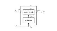
かかるノッチフィルタ7の構成について図4を参照して説明する。図4は、第1の実施形態に係るノッチフィルタ7の構成を示すブロック図である。 The configuration of the notch filter 7 will be described with reference to FIG. FIG. 4 is a block diagram illustrating a configuration of the notch filter 7 according to the first embodiment.
図4に示すように、ノッチフィルタ7は、第1の入力部71と、第2の入力部72と、フィルタリング部73と、減衰制御部74と、出力部75とを備える。 As shown in FIG. 4, the notch filter 7 includes a
第1の入力部71は、外力推定値Tdを入力する。第2の入力部72は、速度検出値vfbを入力する。出力部75は、後述するフィルタリング部73によって振動成分が減衰された外力推定値Td’を出力する。なお、第1の入力部71、第2の入力部72および出力部75は、たとえばポートや端子、ノード等に相当する。The
フィルタリング部73は、第1の入力部71から入力される外力推定値Tdに含まれる振動成分を減衰させる。ノッチフィルタ7がデジタルフィルタである場合、フィルタリング部73の伝達関数G(s)は、
また、ノッチ深さを決めるパラメータであるδは、νをノッチ深さとすると、
減衰制御部74は、第2の入力部72から速度検出値vfbを入力し、入力した速度検出値vfbに応じてフィルタリング部73のノッチ中心周波数ωnを制御する。具体的には、減衰制御部74は、速度検出値vfbの増減に応じてフィルタリング部73のノッチ中心周波数ωnを増減させる。これにより、モータ2の回転速度に応じて周波数が変動する振動成分をフィルタリング部73によって適切に減衰させることができる。The
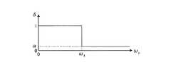
この点について図5Aおよび図5Bを参照して説明する。図5Aおよび図5Bは、第1の実施形態に係るノッチフィルタ7の周波数特性を示す図である。図5Aに示すように、フィルタリング部73は、入力信号の所定の周波数帯域を減衰させる。ここで、ωnはノッチ中心周波数であり、νはノッチ深さである。This point will be described with reference to FIGS. 5A and 5B. 5A and 5B are diagrams illustrating frequency characteristics of the notch filter 7 according to the first embodiment. As shown in FIG. 5A, the filtering unit 73 attenuates a predetermined frequency band of the input signal. Here, ωn is the notch center frequency, and ν is the notch depth.
上述したように、ハーモニック減速機である減速機3は、モータ2の出力軸が1回転する毎に2回振動する、言い換えれば、モータ2の回転速度の2倍の周波数で振動する。したがって、外力推定値Tdに含まれる振動成分は、モータ2の回転速度が速くなるほど高周波となる。As described above, the
そこで、減衰制御部74は、図5Bに示すように、第2の入力部72から入力される速度検出値vfbが高くなるほどフィルタリング部73のノッチ中心周波数ωnを高くし、速度検出値vfbが低くなるほどフィルタリング部73のノッチ中心周波数ωnを低くすることとした。具体的には、ノッチ中心周波数ωnは、ωn=2vfbである。Therefore, as shown in FIG. 5B, the
このように、第1の実施形態では、減速機3の振動の周波数がモータ2の回転速度に応じて増減することに着目し、速度検出値vfbに応じてフィルタリング部73の減衰帯域を移動させることとした。具体的には、減速機3はモータ2の回転速度の2倍の周波数で振動する。このため、減衰制御部74は、ノッチ中心周波数ωnを速度検出値vfbの2倍の周波数に変更することとした。これにより、外力推定値Tdに含まれる振動成分を適切に減衰させることができ、外力推定値の精度を向上させることができる。Thus, in the first embodiment, focusing on the fact that the vibration frequency of the
さらに、減衰制御部74は、第2の入力部72から入力される速度検出値vfbの増減に応じてノッチ深さνも増減させる。以下、この点について説明する。Further, the
上述したように減速機3の振動はモータ2の回転速度が増加するほど高周波となるが、振幅については、モータ2の回転速度に依らずほぼ一定である。これにもかかわらず、第1の実施形態に係るノッチフィルタ7は、モータ2の回転速度が遅いとき、つまり、減速機3の振動が低周波であるときには、ノッチ深さνを浅くする、すなわち、振動成分の減衰量を少なくする。 As described above, the vibration of the
これは、外力推定値Tdの低い周波数帯域に有用な情報が集中しているためであり、低い周波数帯域において振動成分の減衰量を敢えて少なくすることで、外力推定値Tdに含まれる有用な情報を残しつつ不要な振動成分を減衰させることができる。Useful This is because the useful information in a low frequency band of an external force estimation value Td is concentrated, by dare reduce the attenuation of vibration component in a low frequency band, which is included in the external force estimation value Td Unnecessary vibration components can be damped while leaving unnecessary information.
具体的には、図5Bに示すように、減衰制御部74は、ノッチ中心周波数ωnが低くなるほど、つまり、第2の入力部72から入力される速度検出値vfbが低くなるほどフィルタリング部73のノッチ深さνを浅くする。Specifically, as shown in FIG. 5B, the
つづいて、ノッチ深さνの変化のさせ方の一例について図6A〜図6Cを参照して説明する。図6A〜図6Cは、ノッチ中心周波数ωnとノッチ深さνとの関係の一例を示す図である。Next, an example of how to change the notch depth ν will be described with reference to FIGS. 6A to 6C. Figure 6A~ 6C are diagrams showing an example of the relationship between the notch center frequency omegan and notch depth [nu.
なお、図6A〜図6Cには、ノッチ中心周波数ωnを横軸に、ノッチ深さνを決めるパラメータであるδを縦軸にとった場合のωnとδとの関係を示している。上述した式(3)からわかるように、δが1のときにノッチ深さνが0となり、δが0のときにノッチ深さνが無限大となる。6A to 6C show the relationship between ωn and δ when the notch center frequency ωn is taken on the horizontal axis and δ, which is a parameter for determining the notch depth ν, is taken on the vertical axis. As can be seen from Equation (3), the notch depth ν is 0 when δ is 1, and the notch depth ν is infinite when δ is 0.
たとえば、図6Aに示すように、減衰制御部74は、ωn=0のときにδ=1とし、ωnの増加に伴って(すなわち、速度検出値vfbの増加に伴って)δが曲線的に減少するようにフィルタリング部73による減衰の減衰量を制御してもよい。図6Aに示す曲線は、ωn=ω1に変曲点Pを有する曲線(シグモイド曲線)であり、ωn<ω1のときには上に凸、ωn>ω1のときには下に凸となる。For example, as shown in FIG. 6A, the
なお、減衰制御部74は、図6Aに示した曲線に限らず、δが変曲点のない曲線(たとえば指数曲線など)に従って減少するようにフィルタリング部73による減衰の減衰量を制御してもよい。 The
また、図6Bに示すように、2つの閾値ω2,ω3を設け、ωn≦ω2のときにはδ=1で一定とし、ωn≧ω3のときにはδ=α(<1)で一定とし、ω2<ωn<ω3のときには、ωnの増加に伴ってδが1からαへ直線的に減少するように、減衰制御部74がフィルタリング部73の減衰量を制御してもよい。Further, as shown in FIG. 6B, two threshold values ω2 and ω3 are provided. When ωn ≦ ω2 , δ = 1 is constant, and when ωn ≧ ω3 , δ = α (<1) is constant. When ω2 <ωn <ω3 , the
すなわち、減衰制御部74は、ω2/2(第1の閾値)以下の速度検出値vfbが入力された場合には、ノッチ深さνが0となり、かつ、ω3/2(第2の閾値)以上の速度検出値vfbが入力された場合には、ノッチ深さνが0よりも大きい一定量となるようにフィルタリング部73の減衰量を制御してもよい。That is, the
このように、減衰制御部74は、所定の閾値(ここではω3/2)以上の速度検出値vfbが入力された場合のノッチ深さνを一定とする。これは、もともとモータ2の回転に伴う減速機3の振動の振幅がモータ2の回転速度に依らずほぼ一定であるためであり、このようにω3/2以上の回転速度におけるノッチ深さνを一定とすることで、図6Aに示す場合と比較して処理負荷を軽減することができる。Thus, the
なお、ここでは、ω2<ωn<ω3のときに、ωnの増加に伴ってδを直線的に減少させることとしたが、ωnの増加に伴ってδを曲線的に減少させてもよい。また、ここでは、閾値を2つとしたが、閾値は3つ以上であってもよい。Here,, omega2 <when omegan <omega3, omega it is assumedthat n with increasing to linearly decrease the [delta], to reduce the [delta] with the increase of omegan curvedly May be. In addition, although the threshold value is two here, the threshold value may be three or more.
また、図6Cに示すように、1つの閾値ω4を設け、ωn<ω4のときにはδ=1(すなわち、ν=0)で一定となり、ωn≧ω4のときにはδ=αで一定となるように、減衰制御部74がフィルタリング部73の減衰量を制御してもよい。Further, as shown in FIG. 6C, one threshold value ω4 is provided. When ωn <ω4 , δ = 1 (ie, ν = 0) is constant, and when ωn ≧ ω4 , δ = α is constant. The
また、たとえば図6Bの0≦ωn<ω3の部分を図6Aに示すような曲線に置き換えてもよい。すなわち、0≦ωn<ω3のときには、δが図6Aに示すような曲線に従って減少し、ωn≧ω3のときにはδ=αで一定となるように、減衰制御部74がフィルタリング部73の減衰量を制御してもよい。Further, for example, the portion of 0 ≦ ωn <ω3 in FIG. 6B may be replaced with a curve as shown in FIG. 6A. That is, when 0 ≦ ωn <ω3 , δ decreases according to the curve shown in FIG. 6A, and when ωn ≧ ω3 , the
また、図2に示すように、外力推定器30から出力されるフィルタリング後の外力推定値Td’は、モータ制御装置8にフィードバックされる。そして、モータ制御装置8は、かかる外力推定値Td’に基づいてトルク指令を補正し、補正したトルク指令Trefをモータ2へ出力する。Further, as shown in FIG. 2, the filtered external force estimated value Td ′ output from the
たとえば、モータ制御装置8は、補正前のトルク指令から外力推定値Td’を減算したものをトルク指令Trefとして出力するポジティブフィードバックを行う。あるいは、モータ制御装置8は、外力推定値Td’の位相を反転させたうえで、補正前のトルク指令から位相反転後の外力推定値Td’を減算するネガティブフィードバックを行ってもよい。これにより、ロボット1の制御を精度良く行うことができる。For example, the
上述してきたように、第1の実施形態に係るロボットシステム100は、ロボット1と、外力オブザーバ6と、ノッチフィルタ7とを備える。ロボット1は、各関節部21〜24がモータ2と減速機3とを含んで構成される。外力オブザーバ6は、モータ2のトルク検出値Tfbと速度検出値vfbとに基づいて外力推定値Tdを生成する。ノッチフィルタ7は、外力オブザーバ6から出力される外力推定値Tdに含まれる、モータ2の回転に起因する振動成分を減衰させる。また、ノッチフィルタ7は、フィルタリング部73と減衰制御部74とを備える。フィルタリング部73は、外力推定値Tdを取得し、外力推定値Tdに含まれる振動成分の減衰を行う。減衰制御部74は、モータ2の速度検出値vfbを取得し、取得した速度検出値vfbに応じてフィルタリング部73による減衰の減衰量を制御する。As described above, the
したがって、第1の実施形態に係るロボットシステム100によれば、モータ2の回転に伴って発生する振動成分を減衰させることができる。 Therefore, according to the
また、第1の実施形態に係るロボットシステム100では、フィルタリング部73が、モータ2の回転に伴って減速機3が発生させる振動成分を含む外力推定値Tdを取得することとした。これにより、モータ2の回転に伴って減速機3が発生させる振動成分を減衰させることができる。Further, in the
なお、ここでは、モータ2の出力軸が1回転する毎に2回振動する性質を有する減速機3の場合に、ノッチ中心周波数ωnを速度検出値vfbの2倍とする場合の例を示した。これと同様に、モータ2の出力軸が1回転する毎にn回振動する性質を有する減速機3の場合には、ノッチ中心周波数ωnを速度検出値vfbのn倍(nは2以上の整数)とすればよい。また、上記のnは、2以上の整数に限定されない。すなわち、減速機3が、モータ2の出力軸が2回転する毎に3回振動する性質やモータ2の出力軸が3回転する毎に1回振動する性質を有する場合には、ノッチ中心周波数ωnを速度検出値vfbのそれぞれ3/2倍、1/3倍とすればよい。このように、減衰制御部74は、ノッチ中心周波数ωnを速度検出値vfbに比例した周波数に変更するようにしてもよい。Here, in the case of the
また、ここでは、減速機3が、モータ2の回転に応じて振動成分を発生させる減速機である場合の例を示したが、減速機3は、モータ2の回転とは無関係に振動成分を発生させる減速機であってもよい。このような場合であっても、減速機3の振動成分がモータ2の回転に応じて変化する場合には、上述してきたノッチフィルタ7を用いて振動成分を適切に減衰させることができる。 Here, an example in which the
(第2の実施形態)
上述した第1の実施形態では、モータ2の回転速度の増減に応じて、ノッチ中心周波数ωnおよびノッチ深さνの両方を増減させる場合の例について説明したが、ノッチフィルタ7は、ノッチ中心周波数ωnを固定とし、ノッチ深さνのみを増減させる構成であってもよい。(Second Embodiment)
In the first embodiment described above, in accordance with the increase or decrease of the rotational speed of the
かかる点について図7Aおよび図7Bを参照して説明する。図7Aおよび図7Bは、第2の実施形態に係るノッチフィルタ7の周波数特性を示す図である。 This point will be described with reference to FIGS. 7A and 7B. 7A and 7B are diagrams illustrating frequency characteristics of the notch filter 7 according to the second embodiment.
図7Aおよび図7Bに示すように、第2の実施形態に係るノッチフィルタ7の減衰制御部74は、第2の入力部72から入力される速度検出値vfbが変化した場合に、ノッチ中心周波数ωnを変化させることなく、ノッチ深さνのみを変化させる。ノッチ深さνは、たとえば所定の係数k(kは正の数)を用いてν=kvfbとしてもよいし、速度検出値vfbを変数とする所定の関数ν=f(vfb)としてもよい。As shown in FIG. 7A and FIG. 7B, the
第1の実施形態では、減速機3が、ハーモニック減速機である場合を例に挙げて説明した。しかし、減速機3がハーモニック減速機以外の減速機である場合、減速機の種類によっては、モータ2の回転速度の増減に伴って振動成分の振幅が増減する場合もある。 In the first embodiment, the case where the
このような場合には、第2の実施形態に係るノッチフィルタ7のように、速度検出値vfbの増減に応じてノッチ深さνを増減させることで、モータ2の回転に伴って発生する振動成分を減衰させることができる。In such a case, as with the notch filter 7 according to the second embodiment, the notch depth ν is increased / decreased according to the increase / decrease of the speed detection value vfb , and this occurs with the rotation of the
(第3の実施形態)
ところで、上述してきた各実施形態では、外力推定器30が旋回部20および第1〜第4関節部21〜24に設けられる場合の例を示したが、外力推定器30は、たとえばモータ制御装置8に設けられてもよい。以下では、モータ制御装置が、外力推定器30に相当する処理部を備える場合の例について図8を参照して説明する。図8は、第3の実施形態に係るロボットシステムの構成を示すブロック図である。(Third embodiment)
By the way, in each embodiment mentioned above, although the example in case the external
図8に示すように、第3の実施形態に係るロボットシステム100Aにおいて、第1関節部21Aは、第1および第2の実施形態に係る第1関節部21から外力推定器30を除いた構成を有する。他の関節部についても同様に、外力推定器30を除いた構成を有する。 As shown in FIG. 8, in the
第3の実施形態に係るモータ制御装置8Aは、外力推定部30Aと、制御部81とを備える。外力推定部30Aは、外力推定器30に相当する処理部であり、外力推定器30と同様、外力オブザーバ6とノッチフィルタ7とを備える。なお、モータ制御装置8Aは、各関節部に対応する複数の外力推定部30Aを備えるが、ここでは、第1関節部21Aに対応する外力推定部30Aのみを示している。 The motor control device 8A according to the third embodiment includes an external
トルク検出値Tfbおよび速度検出値vfbは、モータ制御装置8Aに設けられた外力推定部30Aに入力される。具体的には、トルク検出値Tfbは外力オブザーバ6に入力され、速度検出値vfbは、外力オブザーバ6およびノッチフィルタ7にそれぞれ入力される。Torque detection value Tfb and speed detection value vfb are input to external
外力推定部30Aでは、上述した外力推定器30と同様、外力オブザーバ6が、トルク検出値Tfbおよび速度検出値vfbに基づいて外力推定値Tdを生成してノッチフィルタ7へ出力し、ノッチフィルタ7が、外力推定値Tdから振動成分を減衰させて、外力推定値Td’を制御部81へ出力する。ノッチフィルタ7は、第1および第2の実施形態において説明した通り、フィルタリング部73および減衰制御部74を備え(図4参照)、減衰制御部74が速度検出値vfbに応じてフィルタリング部73のノッチ中心周波数ωnやノッチ深さνを変更する。これにより、外力推定値Tdに含まれる、モータ2の回転に伴って発生する振動成分を減衰させることができる。In the external
そして、制御部81は、外力推定部30Aから入力される外力推定値Td’に基づいてトルク指令を補正し、補正したトルク指令Trefをモータ2へ出力する。Then, the control unit 81 corrects the torque command based on the external force estimation value Td ′ input from the external
このように、フィルタリング部73および減衰制御部74は、モータ制御装置8Aに設けられていてもよい。 As described above, the filtering unit 73 and the
また、上述してきた各実施形態では、ノッチフィルタ7を外力推定器30や外力推定部30Aに設ける場合の例について説明したが、ノッチフィルタ7は、外力オブザーバ6と別体で、図2に示す制御ループ内の任意の場所に設けられてもよい。 Moreover, although each embodiment mentioned above demonstrated the example in the case of providing the notch filter 7 in the
また、ノッチフィルタ7に入力される入力信号は、モータ2の回転に伴って発生する振動成分を含んだ信号であればよく、外力推定値Tdに限定されない。たとえば、ノッチフィルタ7をトルク検出部4の後段に設けて、トルク検出値Tfbに含まれる振動成分をノッチフィルタ7によって減衰させるようにしてもよい。Further, the input signal input to the notch filter 7 is not limited to the external force estimated valueTd as long as it includes a vibration component generated with the rotation of the
(第4の実施形態)
次に、第4の実施形態に係るロボットシステムの構成について図9を参照して説明する。図9は、第4の実施形態に係るロボットシステムの構成を示すブロック図である。(Fourth embodiment)
Next, the configuration of the robot system according to the fourth embodiment will be described with reference to FIG. FIG. 9 is a block diagram illustrating a configuration of a robot system according to the fourth embodiment.
図9に示すように、第4の実施形態に係るロボットシステム100Bが備える第1関節部21Bは、第1の実施形態に係る第1関節部21(図2参照)から減速機3およびトルク検出部4を除外した構成を有する。 As illustrated in FIG. 9, the first
上述してきた各実施形態では、減速機3が振動成分を発生させる場合の例を示したが、振動成分は、減速機3だけではなく、たとえばモータ2自体の構造等に起因して発生する場合もある。つまり、第4の実施形態に係るロボットシステム100Bのように減速機3を有していない系においても、モータ2の回転に伴って発生する振動成分が外力推定値Tdに含まれる可能性がある。したがって、このような系に対してロボットシステム100Bを適用した場合であっても、モータ2の回転に伴って発生する振動成分を減衰させることができる。In each of the embodiments described above, an example in which the
また、第4の実施形態に係る外力オブザーバ6Bは、上述してきた外力オブザーバ6とは異なり、モータ制御装置8から出力されるトルク指令Trefを用いて外力推定値Tdを推定する。かかる場合、外力オブザーバ6Bは、第1アーム部12等に働く外力、摩擦力およびその他の力の総和、すなわち、外乱を「外力」として推定する。Further, unlike the external force observer 6 described above, the
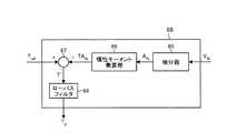
ここで、第4の実施形態に係る外力オブザーバ6Bの構成例について図10を参照して説明する。図10は、第4の実施形態に係る外力オブザーバ6Bの構成例を示すブロック図である。図10に示すように、外力オブザーバ6Bは、微分器65と、慣性モーメント乗算部66と、減算部67と、ローパスフィルタ68とを備える。 Here, a configuration example of the
微分器65は、速度検出値vfbを微分することによって加速度検出値Afbを算出し、算出した加速度検出値Afbを慣性モーメント乗算部66へ出力する。慣性モーメント乗算部66は、微分器65から入力された加速度検出値Afbに対してモータ軸周りの慣性モーメントを乗算することによって加速トルク検出値TAfbを算出し、算出した加速トルク検出値TAfbを減算部67へ出力する。The
減算部67は、加速トルク検出値TAfbからトルク指令Trefを減算し、得られた値T’’をローパスフィルタ68へ出力する。ローパスフィルタ68は、T’’にローパスフィルタをかけた値を外力推定値Tdとして出力する。The
このように、外力オブザーバ6Bは、トルク検出値Tfbに代えてトルク指令Trefを用いて外力推定値Tdを算出してもよい。Thus, the
なお、ここでは、外力推定器30Bが第1関節部21Bに設けられる場合の例を示したが、第3の実施形態と同様、外力推定器30Bに代えて、外力推定器30Bに相当する処理部をモータ制御装置8に設けてもよい。 In addition, although the example in the case where the external force estimator 30B is provided in the first
(第5の実施形態)
次に、第5の実施形態に係るロボットシステムの構成について図11を参照して説明する。図11は、第5の実施形態に係るロボットシステムの構成を示すブロック図である。(Fifth embodiment)
Next, the configuration of the robot system according to the fifth embodiment will be described with reference to FIG. FIG. 11 is a block diagram illustrating a configuration of a robot system according to the fifth embodiment.
図11に示すように、第5の実施形態に係るロボットシステム100Cは、ノッチフィルタ7C1,7C2をさらに備える。ノッチフィルタ7C1は、第1関節部21Cのノッチフィルタ7の後段に設けられ、ノッチフィルタ7C2は、第2関節部22Cのノッチフィルタ7の後段に設けられる。 As shown in FIG. 11, the
また、第1関節部21Cおよび第2関節部22Cは、上述した第1の実施形態に係る第1関節部21と同様の構成である。以下では、第1関節部21Cについてのトルク指令、回転位置、トルク検出値、速度検出値、外力推定値をそれぞれ「Tref_1」、「Pfb_1」、「Tfb_1」、「vfb_1」、「Td_1(Td_1’)」とする。また、第2関節部22Cについては、それぞれ「Tref_2」、「Pfb_2」、「Tfb_2」、「vfb_2」、「Td_2(Td_2’)」とする。Further, the first
ここで、第1関節部21Cの信号には、ロボットシステム100C内の他の系(たとえば、第2関節部22C)において発生した振動成分も含まれ得る。第2関節部22Cにおいても同様である。 Here, the signal of the first
そこで、第5の実施形態に係るロボットシステム100Cでは、ノッチフィルタ7C1,7C2をさらに設け、他の系において発生した振動成分をノッチフィルタ7C1,7C2によって減衰させることとした。 Therefore, in the
たとえば、ノッチフィルタ7C1には、第1関節部21Cのノッチフィルタ7から出力される外力推定値、すなわち、第1関節部21Cの減速機3による振動成分が減衰された外力推定値と、第2関節部22Cの速度検出部5から出力される速度検出値vfb_2とが入力される。そして、ノッチフィルタ7C1は、速度検出値vfb_2に応じたノッチ中心周波数ωnおよびノッチ深さνで、第1関節部21Cのノッチフィルタ7から出力される外力推定値をフィルタリングする。これにより、第1関節部21Cのノッチフィルタ7から出力される外力推定値に含まれる、第2関節部22Cにおいて発生した振動成分を減衰させることができる。フィルタリング後の外力推定値Td_1’は、モータ制御装置8へ出力される。For example, the notch filter 7C1 includes an external force estimated value output from the notch filter 7 of the first
また、ノッチフィルタ7C2には、第2関節部22Cのノッチフィルタ7から出力される外力推定値、すなわち、第2関節部22Cの減速機3による振動成分が減衰された外力推定値と、第1関節部21Cの速度検出部5から出力される速度検出値vfb_1とが入力される。そして、ノッチフィルタ7C2は、速度検出値vfb_1に応じたノッチ中心周波数ωnおよびノッチ深さνで、第2関節部22Cのノッチフィルタ7から出力される外力推定値をフィルタリングする。これにより、第2関節部22Cのノッチフィルタ7から出力される外力推定値に含まれる、第1関節部21Cにおいて発生した振動成分を減衰させることができる。フィルタリング後の外力推定値Td_2’は、モータ制御装置8へ出力される。Further, the notch filter 7C2 includes an external force estimated value output from the notch filter 7 of the second
このように、第5の実施形態に係るロボットシステム100Cによれば、ノッチフィルタ7C1,7C2を設けることで、他の系において発生した振動成分も減衰させることができる。 Thus, according to the
なお、ここでは、第1関節部21Cのノッチフィルタ7の後段に、第2関節部22Cにおいて発生した振動成分を減衰させるためのノッチフィルタ7C1を設ける場合の例を示した。しかし、これに限ったものではなく、ノッチフィルタ7の後段には、ノッチフィルタ7C1に加え、第2関節部22C以外の関節部において発生した振動成分を減衰させるノッチフィルタがさらに設けられてもよい。 Here, an example in which the notch filter 7C1 for attenuating the vibration component generated in the second
また、ここでは、ノッチフィルタ7C1,7C2が、たとえば第1関節部21Cおよび第2関節部22Cの外部に設けられる場合の例を示したが、ノッチフィルタ7C1,7C2は、それぞれ第1関節部21Cおよび第2関節部22Cの内部に設けられてもよいし、モータ制御装置8の内部に設けられてもよい。 Here, an example in which the notch filters 7C1 and 7C2 are provided outside the first
また、第3の実施形態と同様、外力推定器30を第1関節部21Cおよび第2関節部22Cから除外し、外力推定器30に相当する処理部をモータ制御装置8に設けてもよい。 Similarly to the third embodiment, the
また、第4の実施形態と同様、外力オブザーバ6は、トルク検出値Tfbに代えてトルク指令Trefを用いて外力推定値Tdを算出してもよい。Further, as in the fourth embodiment, the external force observer 6 may calculate the estimated external force Td using the torque command Tref instead of the detected torque value Tfb .
また、モータ2は、回転型に限らず直動型のリニアモータであってもよい。かかる場合、並進力が上述したトルクに相当し、並進速度が上述した回転速度に相当する。また、モータ2は、電気モータに限らず流体圧アクチュエータなどであってもよい。 Further, the
また、上述してきた各実施形態では、外力推定器30をロボット1に適用した例について説明したが、外力推定器30が適用されるロボットの構成は、図1に示したものに限定されない。また、外力推定器30は、ロボット1に限らず、モータ2によって駆動されるあらゆるものに適用することができる。 Moreover, although each embodiment mentioned above demonstrated the example which applied the
さらなる効果や変形例は、当業者によって容易に導き出すことができる。このため、本発明のより広範な態様は、以上のように表しかつ記述した特定の詳細および代表的な実施形態に限定されるものではない。したがって、添付の特許請求の範囲およびその均等物によって定義される総括的な発明の概念の精神または範囲から逸脱することなく、様々な変更が可能である。 Further effects and modifications can be easily derived by those skilled in the art. Thus, the broader aspects of the present invention are not limited to the specific details and representative embodiments shown and described above. Accordingly, various modifications can be made without departing from the spirit or scope of the general inventive concept as defined by the appended claims and their equivalents.
1 ロボット
2 モータ
3 減速機
4 トルク検出部
5 速度検出部
6 外力オブザーバ
7 ノッチフィルタ
8 モータ制御装置
10 基台
11 胴部
12 第1アーム部
13 第2アーム部
14 リスト部
20 旋回部
21〜24 第1〜第4関節部
30 外力推定器
71 第1の入力部
72 第2の入力部
73 フィルタリング部
74 減衰制御部
75 出力部
100 ロボットシステムDESCRIPTION OF
Claims (12)
Translated fromJapanese前記モータの回転速度に応じて前記減衰の減衰量を制御する減衰制御部と
を備えることを特徴とするノッチフィルタ。A filtering unit that obtains a signal including a vibration component generated with rotation of the motor and attenuates the vibration component;
A notch filter comprising: an attenuation control unit that controls an attenuation amount of the attenuation according to a rotation speed of the motor.
前記モータの回転速度に応じて前記減衰の減衰帯域の中心周波数を制御すること
を特徴とする請求項1に記載のノッチフィルタ。The attenuation control unit includes:
The notch filter according to claim 1, wherein a center frequency of the attenuation band of the attenuation is controlled according to a rotation speed of the motor.
前記モータの回転に伴って減速機が発生させる前記振動成分を含む信号を取得すること
を特徴とする請求項1に記載のノッチフィルタ。The filtering unit includes:
2. The notch filter according to claim 1, wherein a signal including the vibration component generated by the speed reducer with the rotation of the motor is acquired.
前記モータの回転速度に応じて変動する前記振動成分を含む信号を取得すること
を特徴とする請求項3に記載のノッチフィルタ。The filtering unit includes:
The notch filter according to claim 3, wherein a signal including the vibration component that varies in accordance with a rotation speed of the motor is acquired.
前記モータの回転に伴ってハーモニック減速機が発生させる前記振動成分を含む信号を取得すること
を特徴とする請求項3に記載のノッチフィルタ。The filtering unit includes:
4. The notch filter according to claim 3, wherein a signal including the vibration component generated by a harmonic reduction gear as the motor rotates is acquired.
前記中心周波数を前記回転速度に比例した周波数に変更すること
を特徴とする請求項2に記載のノッチフィルタ。The attenuation control unit includes:
The notch filter according to claim 2, wherein the center frequency is changed to a frequency proportional to the rotation speed.
前記中心周波数を前記回転速度のn倍(nは2以上の整数)の周波数に変更すること
を特徴とする請求項2に記載のノッチフィルタ。The attenuation control unit includes:
The notch filter according to claim 2, wherein the center frequency is changed to a frequency that is n times the rotation speed (n is an integer of 2 or more).
前記回転速度が所定の閾値以上である場合には、前記回転速度に依らず前記減衰量を0よりも多い一定量とすること
を特徴とする請求項1に記載のノッチフィルタ。The attenuation control unit includes:
2. The notch filter according to claim 1, wherein when the rotation speed is equal to or greater than a predetermined threshold, the attenuation amount is set to a constant amount greater than 0 regardless of the rotation speed.
前記回転速度が第1の閾値以下である場合には前記減衰量を0とし、かつ、前記回転速度が前記第1の閾値よりも大きい第2の閾値以上である場合には、前記回転速度に依らず前記減衰量を0よりも多い一定量とすること
を特徴とする請求項1に記載のノッチフィルタ。The attenuation control unit includes:
When the rotational speed is less than or equal to the first threshold, the attenuation is set to 0, and when the rotational speed is greater than or equal to the second threshold greater than the first threshold, the rotational speed is reduced to the rotational speed. 2. The notch filter according to claim 1, wherein the amount of attenuation is a constant amount greater than zero.
前記外力オブザーバから出力される外力推定値に含まれる、前記モータの回転に伴って発生する振動成分を減衰させるノッチフィルタと
を備え、
前記ノッチフィルタは、
前記外力推定値を取得して、前記振動成分の減衰を行うフィルタリング部と、
前記モータの回転速度に応じて前記減衰の減衰量を制御する減衰制御部と
を備えることを特徴とする外力推定器。An external force observer that generates an external force estimate based on information on the torque of the motor and information on the rotational speed;
A notch filter that attenuates a vibration component that is included in the estimated external force output from the external force observer and that occurs with the rotation of the motor, and
The notch filter is
A filtering unit that obtains the estimated external force value and attenuates the vibration component;
An external force estimator comprising: an attenuation control unit that controls an attenuation amount of the attenuation according to a rotation speed of the motor.
前記モータの回転速度に応じて前記減衰の減衰量を制御する減衰制御部と
を備えることを特徴とするモータ制御装置。A filtering unit that obtains a signal including a vibration component generated with rotation of the motor and attenuates the vibration component;
A motor control device comprising: an attenuation control unit that controls an attenuation amount of the attenuation according to a rotation speed of the motor.
前記モータのトルクに関する情報と回転速度に関する情報とに基づいて外力推定値を生成する外力オブザーバと、
前記外力オブザーバから出力される外力推定値に含まれる、前記モータの回転に伴って発生する振動成分を減衰させるノッチフィルタと
を備え、
前記ノッチフィルタは、
前記外力推定値を取得して、前記振動成分の減衰を行うフィルタリング部と、
前記モータの回転速度に応じて前記減衰の減衰量を制御する減衰制御部と
を備えることを特徴とするロボットシステム。A robot in which each joint part includes a motor;
An external force observer that generates an external force estimate based on information on the torque of the motor and information on the rotational speed;
A notch filter that attenuates a vibration component that is included in the estimated external force output from the external force observer and that occurs with the rotation of the motor, and
The notch filter is
A filtering unit that obtains the estimated external force value and attenuates the vibration component;
A robot system comprising: an attenuation control unit that controls an attenuation amount of the attenuation according to a rotation speed of the motor.
Applications Claiming Priority (1)
| Application Number | Priority Date | Filing Date | Title |
|---|---|---|---|
| PCT/JP2013/058994WO2014155559A1 (en) | 2013-03-27 | 2013-03-27 | Notch filter, external force estimator, motor controller, and robot system |
Publications (1)
| Publication Number | Publication Date |
|---|---|
| JPWO2014155559A1true JPWO2014155559A1 (en) | 2017-02-16 |
Family
ID=51622637
Family Applications (1)
| Application Number | Title | Priority Date | Filing Date |
|---|---|---|---|
| JP2015507766APendingJPWO2014155559A1 (en) | 2013-03-27 | 2013-03-27 | Notch filter, external force estimator, motor controller and robot system |
Country Status (3)
| Country | Link |
|---|---|
| US (1) | US20160016310A1 (en) |
| JP (1) | JPWO2014155559A1 (en) |
| WO (1) | WO2014155559A1 (en) |
Families Citing this family (10)
| Publication number | Priority date | Publication date | Assignee | Title |
|---|---|---|---|---|
| CN105196294B (en)* | 2015-10-29 | 2017-03-22 | 长春工业大学 | Reconfigurable mechanical arm decentralized control system and control method adopting position measuring |
| JP6717093B2 (en)* | 2016-07-15 | 2020-07-01 | Agc株式会社 | Laminated glass |
| EP3522367B1 (en)* | 2016-09-29 | 2022-03-09 | Panasonic Intellectual Property Management Co., Ltd. | Motor control device and motor control method |
| RU171584U1 (en)* | 2017-01-09 | 2017-06-06 | Акционерное общество "Омский научно-исследовательский институт приборостроения" (АО "ОНИИП") | Tunable notch filter |
| JP7051045B2 (en)* | 2017-11-08 | 2022-04-11 | オムロン株式会社 | Mobile manipulators, control methods and programs for mobile manipulators |
| JP2019162011A (en)* | 2018-03-16 | 2019-09-19 | 株式会社リコー | Motor control device and motor control method |
| CN109474222B (en)* | 2018-12-28 | 2020-10-30 | 中国地质大学(武汉) | Variable load servo system vibration suppression method and system based on notch filter |
| JP7388870B2 (en)* | 2019-10-18 | 2023-11-29 | ファナック株式会社 | Robot systems and control equipment |
| DK180673B1 (en) | 2019-12-29 | 2021-11-25 | Universal Robots As | Method of obtaining vibrational properties of robot arm |
| CN115629533A (en)* | 2022-10-06 | 2023-01-20 | 北京理工大学 | High-frequency resonance suppression method for flexible robot joint harmonic reducer |
Citations (1)
| Publication number | Priority date | Publication date | Assignee | Title |
|---|---|---|---|---|
| JP2011035967A (en)* | 2009-07-30 | 2011-02-17 | Sumitomo Heavy Ind Ltd | Device for controlling electric machine |
Family Cites Families (14)
| Publication number | Priority date | Publication date | Assignee | Title |
|---|---|---|---|---|
| US6710965B2 (en)* | 2001-10-02 | 2004-03-23 | Seagate Technology Llc | Phase-advanced filter for robust resonance cancellation |
| US7689320B2 (en)* | 2005-12-20 | 2010-03-30 | Intuitive Surgical Operations, Inc. | Robotic surgical system with joint motion controller adapted to reduce instrument tip vibrations |
| US20070170379A1 (en)* | 2006-01-24 | 2007-07-26 | Nikon Corporation | Cooled optical filters and optical systems comprising same |
| US7528203B2 (en)* | 2006-09-14 | 2009-05-05 | Exxonmobil Chemical Patents Inc. | Cyclic olefin copolymers, and methods of making the same |
| WO2008066035A1 (en)* | 2006-11-30 | 2008-06-05 | Mitsubishi Electric Corporation | Seismic isolation control system |
| JP2008312339A (en)* | 2007-06-14 | 2008-12-25 | Panasonic Corp | Electric motor control device |
| US20090218521A1 (en)* | 2008-02-08 | 2009-09-03 | Nikon Corporation | Gaseous neutral density filters and related methods |
| JP5124311B2 (en)* | 2008-03-07 | 2013-01-23 | 富士機械製造株式会社 | Actuator |
| US9895813B2 (en)* | 2008-03-31 | 2018-02-20 | Intuitive Surgical Operations, Inc. | Force and torque sensing in a surgical robot setup arm |
| JP2012525591A (en)* | 2009-04-27 | 2012-10-22 | プロテイン・デイスカバリー・インコーポレーテツド | Programmable electrophoresis notch filter system and method |
| JP5326786B2 (en)* | 2009-05-11 | 2013-10-30 | トヨタ自動車株式会社 | Voltage converter controller |
| JP5170175B2 (en)* | 2010-06-30 | 2013-03-27 | 株式会社安川電機 | Robot system |
| JP5324623B2 (en)* | 2011-06-24 | 2013-10-23 | 本田技研工業株式会社 | Vehicle drive control device |
| US8874258B2 (en)* | 2011-09-13 | 2014-10-28 | Persimmon Technologies Corporation | Method for transporting a substrate with a substrate support |
- 2013
- 2013-03-27JPJP2015507766Apatent/JPWO2014155559A1/enactivePending
- 2013-03-27WOPCT/JP2013/058994patent/WO2014155559A1/enactiveApplication Filing
- 2015
- 2015-09-25USUS14/864,876patent/US20160016310A1/ennot_activeAbandoned
Patent Citations (1)
| Publication number | Priority date | Publication date | Assignee | Title |
|---|---|---|---|---|
| JP2011035967A (en)* | 2009-07-30 | 2011-02-17 | Sumitomo Heavy Ind Ltd | Device for controlling electric machine |
Also Published As
| Publication number | Publication date |
|---|---|
| WO2014155559A1 (en) | 2014-10-02 |
| US20160016310A1 (en) | 2016-01-21 |
Similar Documents
| Publication | Publication Date | Title |
|---|---|---|
| WO2014155559A1 (en) | Notch filter, external force estimator, motor controller, and robot system | |
| US9796087B2 (en) | Control system for power unit | |
| JP5644409B2 (en) | Electric motor position control device | |
| JP6491497B2 (en) | Motor control device | |
| JP6007831B2 (en) | Power system test equipment | |
| JP4914979B2 (en) | Motor control device and motor control method | |
| JP6197923B1 (en) | Control system | |
| US11669055B2 (en) | Vibration suppression device, method and computer-readable medium using estimated vibration torque | |
| KR20080041693A (en) | System identification devices | |
| JP2015170208A (en) | Control device, control method, and control program | |
| JP2018165618A (en) | Signal processing device, detection device, physical quantity measuring device, electronic device, and moving object | |
| KR101417486B1 (en) | Method and system for extracting intended torque for wearable robot | |
| JP2019219762A (en) | Control device, control method and program | |
| CN111025915B (en) | Z-axis gyroscope neural network sliding mode control method based on disturbance observer | |
| JP5176729B2 (en) | Motor controller with moment of inertia identifier | |
| CN112134504A (en) | Control device for inertia evaluation and inertia evaluation method | |
| JP6064694B2 (en) | Power system test equipment | |
| Brock et al. | Selected methods for a robust control of direct drive with a multi-mass mechanical load | |
| Kubus et al. | A sensor fusion approach to angle and angular rate estimation | |
| TWI506943B (en) | Signal processing apparatus for time variant signal | |
| JP2007020297A (en) | System identification device and system identification method thereof | |
| JP5444929B2 (en) | Chassis dynamometer system | |
| Vo-Duy et al. | Modified Multirate Kalman Filter for Improving the Sampling Frequency of Single Low Speed Sensor | |
| JP6544056B2 (en) | Motor controller | |
| JP2023084722A (en) | Torque compensation device and torque compensation method |
Legal Events
| Date | Code | Title | Description |
|---|---|---|---|
| A02 | Decision of refusal | Free format text:JAPANESE INTERMEDIATE CODE: A02 Effective date:20161129 |