JPWO2014024653A1 - Biological information measuring device and pulse oximeter - Google Patents
Biological information measuring device and pulse oximeterDownload PDFInfo
- Publication number
- JPWO2014024653A1 JPWO2014024653A1JP2014529406AJP2014529406AJPWO2014024653A1JP WO2014024653 A1JPWO2014024653 A1JP WO2014024653A1JP 2014529406 AJP2014529406 AJP 2014529406AJP 2014529406 AJP2014529406 AJP 2014529406AJP WO2014024653 A1JPWO2014024653 A1JP WO2014024653A1
- Authority
- JP
- Japan
- Prior art keywords
- biological information
- measuring device
- information measuring
- finger
- main body
- Prior art date
- Legal status (The legal status is an assumption and is not a legal conclusion. Google has not performed a legal analysis and makes no representation as to the accuracy of the status listed.)
- Pending
Links
- 238000012545processingMethods0.000claimsabstractdescription31
- 238000003780insertionMethods0.000claimsdescription30
- 230000037431insertionEffects0.000claimsdescription30
- 238000005259measurementMethods0.000claimsdescription23
- 238000004891communicationMethods0.000claimsdescription18
- 239000008280bloodSubstances0.000claimsdescription12
- 210000004369bloodAnatomy0.000claimsdescription12
- QVGXLLKOCUKJST-UHFFFAOYSA-Natomic oxygenChemical compound[O]QVGXLLKOCUKJST-UHFFFAOYSA-N0.000claimsdescription10
- 229910052760oxygenInorganic materials0.000claimsdescription10
- 239000001301oxygenSubstances0.000claimsdescription10
- 210000001503jointAnatomy0.000claimsdescription3
- 102000004190EnzymesHuman genes0.000claimsdescription2
- 108090000790EnzymesProteins0.000claimsdescription2
- 238000010586diagramMethods0.000description18
- 238000006243chemical reactionMethods0.000description10
- 238000012986modificationMethods0.000description7
- 230000004048modificationEffects0.000description7
- 238000004458analytical methodMethods0.000description6
- 238000000034methodMethods0.000description5
- 238000004519manufacturing processMethods0.000description4
- 238000005452bendingMethods0.000description3
- 239000011347resinSubstances0.000description2
- 229920005989resinPolymers0.000description2
- 239000000523sampleSubstances0.000description2
- 210000000707wristAnatomy0.000description2
- HBBGRARXTFLTSG-UHFFFAOYSA-NLithium ionChemical compound[Li+]HBBGRARXTFLTSG-UHFFFAOYSA-N0.000description1
- XUIMIQQOPSSXEZ-UHFFFAOYSA-NSiliconChemical compound[Si]XUIMIQQOPSSXEZ-UHFFFAOYSA-N0.000description1
- 238000013459approachMethods0.000description1
- 230000005540biological transmissionEffects0.000description1
- 238000004364calculation methodMethods0.000description1
- 230000008859changeEffects0.000description1
- 238000007405data analysisMethods0.000description1
- 230000007423decreaseEffects0.000description1
- 230000005674electromagnetic inductionEffects0.000description1
- 210000001145finger jointAnatomy0.000description1
- 230000006870functionEffects0.000description1
- 229910001416lithium ionInorganic materials0.000description1
- 230000007246mechanismEffects0.000description1
- 230000015654memoryEffects0.000description1
- 229910052987metal hydrideInorganic materials0.000description1
- 229910052759nickelInorganic materials0.000description1
- PXHVJJICTQNCMI-UHFFFAOYSA-NnickelSubstances[Ni]PXHVJJICTQNCMI-UHFFFAOYSA-N0.000description1
- -1nickel metal hydrideChemical class0.000description1
- 230000003287optical effectEffects0.000description1
- 239000002861polymer materialSubstances0.000description1
- 230000009467reductionEffects0.000description1
- 230000035945sensitivityEffects0.000description1
- 229910052710siliconInorganic materials0.000description1
- 239000010703siliconSubstances0.000description1
- 239000007787solidSubstances0.000description1
- 238000012360testing methodMethods0.000description1
- 238000004804windingMethods0.000description1
Images


Classifications
- A—HUMAN NECESSITIES
- A61—MEDICAL OR VETERINARY SCIENCE; HYGIENE
- A61B—DIAGNOSIS; SURGERY; IDENTIFICATION
- A61B5/00—Measuring for diagnostic purposes; Identification of persons
- A61B5/145—Measuring characteristics of blood in vivo, e.g. gas concentration or pH-value ; Measuring characteristics of body fluids or tissues, e.g. interstitial fluid or cerebral tissue
- A61B5/1455—Measuring characteristics of blood in vivo, e.g. gas concentration or pH-value ; Measuring characteristics of body fluids or tissues, e.g. interstitial fluid or cerebral tissue using optical sensors, e.g. spectral photometrical oximeters
- A61B5/14551—Measuring characteristics of blood in vivo, e.g. gas concentration or pH-value ; Measuring characteristics of body fluids or tissues, e.g. interstitial fluid or cerebral tissue using optical sensors, e.g. spectral photometrical oximeters for measuring blood gases
- A61B5/14552—Details of sensors specially adapted therefor
- A—HUMAN NECESSITIES
- A61—MEDICAL OR VETERINARY SCIENCE; HYGIENE
- A61B—DIAGNOSIS; SURGERY; IDENTIFICATION
- A61B5/00—Measuring for diagnostic purposes; Identification of persons
- A61B5/02—Detecting, measuring or recording for evaluating the cardiovascular system, e.g. pulse, heart rate, blood pressure or blood flow
- A61B5/024—Measuring pulse rate or heart rate
- A—HUMAN NECESSITIES
- A61—MEDICAL OR VETERINARY SCIENCE; HYGIENE
- A61B—DIAGNOSIS; SURGERY; IDENTIFICATION
- A61B5/00—Measuring for diagnostic purposes; Identification of persons
- A61B5/68—Arrangements of detecting, measuring or recording means, e.g. sensors, in relation to patient
- A61B5/6801—Arrangements of detecting, measuring or recording means, e.g. sensors, in relation to patient specially adapted to be attached to or worn on the body surface
- A61B5/6813—Specially adapted to be attached to a specific body part
- A61B5/6825—Hand
- A61B5/6826—Finger
Landscapes
- Health & Medical Sciences (AREA)
- Life Sciences & Earth Sciences (AREA)
- Physics & Mathematics (AREA)
- Medical Informatics (AREA)
- Surgery (AREA)
- Biophysics (AREA)
- Pathology (AREA)
- Engineering & Computer Science (AREA)
- Biomedical Technology (AREA)
- Heart & Thoracic Surgery (AREA)
- Veterinary Medicine (AREA)
- Molecular Biology (AREA)
- Public Health (AREA)
- Animal Behavior & Ethology (AREA)
- General Health & Medical Sciences (AREA)
- Cardiology (AREA)
- Optics & Photonics (AREA)
- Spectroscopy & Molecular Physics (AREA)
- Physiology (AREA)
- Measurement Of The Respiration, Hearing Ability, Form, And Blood Characteristics Of Living Organisms (AREA)
- Measuring Pulse, Heart Rate, Blood Pressure Or Blood Flow (AREA)
Abstract
Translated fromJapaneseDescription
Translated fromJapanese本発明は、生体情報測定装置、およびパルスオキシメータに関する。 The present invention relates to a biological information measuring device and a pulse oximeter.
血液中の酸素飽和度(SpO2)を測定可能なパルスオキシメータが知られている。このパルスオキシメータでは、被験者の生体部位に装着される測定部において、生体部位に向けて光が照射され、生体部位を透過または生体部位で反射した光の光量に基づいてSpO2が導出される。A pulse oximeter capable of measuring oxygen saturation (SpO2 ) in blood is known. In this pulse oximeter, light is irradiated toward a living body part in a measurement unit attached to the living body part of a subject, and SpO2 is derived based on the amount of light transmitted through or reflected by the living body part. .
このパルスオキシメータについては、一体型のハウジング内に、光源、センサー、プロセッサーおよびアンプ等が配されている装置が提案されている(例えば、特許文献1等)。これにより、装置の製造コストが低減されるとともに、装置が壊れ難い。また、本体部が手首に装着され、プローブが帯状のテープで指に固定される装置が提案されている(例えば、特許文献2等)。 As for the pulse oximeter, a device in which a light source, a sensor, a processor, an amplifier, and the like are arranged in an integrated housing has been proposed (for example, Patent Document 1). Thereby, the manufacturing cost of the apparatus is reduced and the apparatus is hardly broken. In addition, an apparatus has been proposed in which the main body is attached to the wrist and the probe is fixed to a finger with a strip-shaped tape (for example, Patent Document 2).
しかしながら、上記特許文献1の技術では、堅牢な一体型のハウジングが指に装着されるため、指の間接部分を曲げることが難しく、装置の長時間の装着は被験者にとって大きな負担となる。また、上記特許文献2の技術では、テープを指に巻くことで装置を指に固定する作業が繁雑であり、手首に装着された本体部およびこの本体部から指に固定されたプローブまで伸びるケーブルの存在によって装置の長時間の装着が被験者にとって大きな負担となる。 However, in the technique of the above-mentioned patent document 1, since a solid integrated housing is attached to the finger, it is difficult to bend the indirect part of the finger, and wearing the device for a long time is a heavy burden on the subject. Moreover, in the technique of the above-mentioned
本発明は、上記課題に鑑みてなされたものであり、指への装着が容易であり且つ長時間の指への装着による被験者への負担が軽減され得る生体情報測定装置およびパルスオキシメータを提供することを目的とする。 The present invention has been made in view of the above problems, and provides a biological information measurement device and a pulse oximeter that can be easily attached to the finger and can reduce the burden on the subject due to the attachment to the finger for a long time. The purpose is to do.
上記課題を解決するために、一態様に係る生体情報測定装置は、本体部と、該本体部に固定されており且つ生体の指を挟持するための装着部とを備え、前記装着部によって前記指が挟持される際に前記指が配される領域を挟んで対向している光源部と受光部とを含んでいる。該生体情報測定装置では、前記本体部が、信号処理部を含む電気回路と電源部とを有しており、前記信号処理部が、前記光源部から発せられて前記指を透過した光が前記受光部で受光されることによって前記受光部から出力される信号から脈波に係るデジタル値を取得する。そして、該生体情報測定装置では、前記本体部の長手方向における該本体部の第1長さは、該長手方向における前記装着部の第2長さよりも長くなっている。 In order to solve the above-described problem, a biological information measuring device according to one aspect includes a main body portion and a mounting portion that is fixed to the main body portion and holds a finger of a living body. It includes a light source unit and a light receiving unit facing each other across a region where the finger is arranged when the finger is clamped. In the biological information measuring apparatus, the main body unit includes an electric circuit including a signal processing unit and a power source unit, and the signal processing unit emits light transmitted from the light source unit and transmitted through the finger. A digital value related to a pulse wave is acquired from a signal output from the light receiving unit by receiving light at the light receiving unit. In the biological information measuring device, the first length of the main body portion in the longitudinal direction of the main body portion is longer than the second length of the mounting portion in the longitudinal direction.
他の一態様に係るパルスオキシメータは、本体部と、該本体部に固定されており且つ生体の指を挟持するための装着部とを備え、前記装着部によって前記指が挟持される際に前記指が配される領域を挟んで対向している光源部と受光部とを含んでいる。該パルスオキシメータでは、前記本体部が、信号処理部を含む電気回路と電源部とを有しており、前記信号処理部が、前記光源部から発せられて前記指を透過した光が前記受光部で受光されることによって前記受光部から出力される信号から、血液中の酵素飽和度に係る値を取得する。そして、該パルスオキシメータでは、前記本体部の長手方向における該本体部の第1長さは、該長手方向における前記装着部の第2長さよりも長くなっている。 A pulse oximeter according to another aspect includes a main body portion and a mounting portion that is fixed to the main body portion and clamps a biological finger, and the finger is clamped by the mounting portion. It includes a light source part and a light receiving part facing each other across an area where the finger is arranged. In the pulse oximeter, the main body includes an electric circuit including a signal processing unit and a power supply unit, and the signal processing unit receives light emitted from the light source unit and transmitted through the finger. A value related to the degree of enzyme saturation in the blood is obtained from the signal output from the light receiving unit by receiving light at the unit. In the pulse oximeter, the first length of the main body portion in the longitudinal direction of the main body portion is longer than the second length of the mounting portion in the longitudinal direction.
一態様に係る生体情報測定装置および他の一態様に係るパルスオキシメータの何れによっても、装置の指への装着が容易であり且つ長時間の指への装着による被験者への負担が軽減され得る。 With either the biological information measurement device according to one aspect or the pulse oximeter according to another aspect, it is easy to attach the device to the finger, and the burden on the subject due to long-time finger attachment can be reduced. .
以下、本発明の実施形態を図面に基づいて説明する。なお、図面においては同様な構成および機能を有する部分については同じ符号が付されており、下記説明では重複説明が省略される。また、図面は模式的に示されたものであり、各図における各種構造のサイズおよび位置関係等は正確に図示されたものではない。なお、図1から図5および図8から図12には、生体情報測定装置1の長手方向の一方向(図1の図面視右方向)を+X方向とする右手系のXYZ座標系が付されている。 Hereinafter, embodiments of the present invention will be described with reference to the drawings. In the drawings, parts having the same configuration and function are denoted by the same reference numerals, and redundant description is omitted in the following description. Further, the drawings are schematically shown, and the sizes, positional relationships, and the like of various structures in the drawings are not accurately illustrated. 1 to 5 and FIGS. 8 to 12 are provided with a right-handed XYZ coordinate system in which one direction in the longitudinal direction of the biological information measuring apparatus 1 (the right direction in the drawing of FIG. 1) is the + X direction. ing.
<(1)一実施形態>
<(1−1)生体情報測定装置の構成>
一実施形態に係る生体情報測定装置1は、例えば、光源部4から発せられて指を透過した光が受光部5で受光されることによって受光部5から出力される信号から、血液中の酸素飽和度に係るデジタル値(SpO2値)を取得するパルスオキシメータである。<(1) One Embodiment>
<(1-1) Configuration of Biological Information Measuring Device>
The biological information measuring apparatus 1 according to the embodiment includes, for example, oxygen in blood from a signal output from the
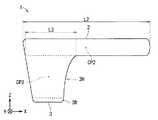
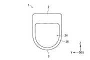
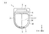
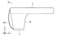
図1から図3は、生体情報測定装置1の外観を模式的に示す図である。図1には、生体情報測定装置1を側方から見た図が示されている。図2には、生体情報測定装置1を正面から見た図が示されている。図3では、生体情報測定装置1を上方から見た図が示されている。また、図4および図5は、生体情報測定装置1の構成を模式的に示す図である。図5には、図4の一点鎖線V−Vで示した位置におけるYZ断面が示されている。 FIG. 1 to FIG. 3 are diagrams schematically showing the appearance of the biological information measuring apparatus 1. The figure which looked at the biological information measuring device 1 from the side is shown by FIG. The figure which looked at the biological information measuring device 1 from the front is shown by FIG. In FIG. 3, the figure which looked at the biological information measuring device 1 from the upper side is shown. 4 and 5 are diagrams schematically showing the configuration of the biological information measuring device 1. FIG. FIG. 5 shows a YZ cross section at the position indicated by the one-dot chain line VV in FIG.
図1から図3で示されるように、生体情報測定装置1は、本体部2と装着部3とを備えている。 As shown in FIG. 1 to FIG. 3, the biological information measuring device 1 includes a
本体部2は、筐体2h、ならびに該筐体2h内に配されている電気回路6、電源部7、充電回路8、通信部9および操作部10を備えている。筐体2hは、例えば、略直方体の形状を有している。ここで、筐体2hが装着部3よりも硬く十分な剛性を持つことで、本体部2に格納される各種構成が壊れ難くなる。 The
装着部3は、本体部2に固定されており、生体の各種情報を測定する際に生体の指を挟持するための部分である。ここで、装着部3が筐体2hよりも相対的に柔らかければ、被験者における生体情報測定装置1の装着感が良好となり得る。該装着部3は、例えば、指を挟持するための弾性力を発する弾性体を含んでいれば良い。該弾性体としては、例えば、ゴム等の高分子材料およびバネ等が採用され得る。具体的には、例えば、装着部3の略全体が弾性を有するゴム等の樹脂によって構成される態様、および略U字状の板バネが樹脂に埋め込まれた態様等が採用され得る。 The
ここでは、本体部2の長手方向としてのX方向における長さ(第1長さとも言う)L2が、該長手方向としてのX方向における装着部3の長さ(第2長さとも言う)L3よりも長い。ここで、上記のように、本体部2は、筐体2h内に、電気回路6、電源部7、充電回路8、通信部9および操作部10の各種構成を備えているので、該筐体2hに剛性を持たせている。このため、指の動作の妨げとならない観点から言えば、本体部2が指の長手方向に沿ってある程度の長さを持つような形状にして上記各種構成を筐体2h内に配置させることが有効である。例えば、第1長さL2が、第2長さL3の2倍以上の長さである場合が考えられる。さらに、装着部3のX方向における中心位置CP3は、本体部2のX方向における中心位置CP2から本体部2のうちの長手方向における一端部側(−X側の端部)に向けた一方向(−X方向)にずれている。そして、生体情報測定装置1は、光源部4と受光部5とを備えている。この光源部4と受光部5とは、装着部3によって指が挟持される際に指が配される領域を挟んで対向している。光源部4および受光部5は、本体部2および装着部3の何れに配されても良い。 Here, the length (also referred to as the first length) L2 in the X direction as the longitudinal direction of the
ここで、例えば、装着部3は、生体の指が−X方向に挿入される挿入孔3Hを有する環状部3Rを含んでいれば、挿入孔3Hが、装着部3において指が挟持される領域となる。この場合、挿入孔3Hへの指の挿入によって、生体情報測定装置1の指への装着が非常に容易に行われ得る。さらに、挿入孔3Hへ挿入された指に対する負担が小さいため、生体情報測定装置1の長時間の指への装着による被験者への負担がさらに軽減され得る。そして、装着部3の弾性体によって発生する弾性力によって、挿入孔3Hが閉じる方向に環状部3Rが変形される構成が採用されれば、生体情報測定装置1が指に安定的に装着され得る。 Here, for example, if the mounting
以上のような構成を有する生体情報測定装置1が採用されれば、装置の指への装着が容易である。また、生体情報測定装置1が指に装着された状態では、装着部3が小型であるために、指の関節を曲げる動作の妨げとなり難く、さらに指先側に本体部2が突出し難い。したがって、装置の長時間の指への装着による被験者への負担が軽減され得る。 If the biological information measuring apparatus 1 having the above configuration is employed, the apparatus can be easily attached to the finger. In addition, when the biological information measuring device 1 is attached to a finger, the
<(1−2)生体情報測定装置の機能的な構成>
図6および図7は、生体情報測定装置1の機能的な構成を示すブロック図である。<(1-2) Functional Configuration of Biological Information Measuring Device>
6 and 7 are block diagrams showing a functional configuration of the biological information measuring device 1. FIG.
図6で示されるように、生体情報測定装置1は、光源部4、受光部5、電気回路6、電源部7、充電回路8、通信部9および操作部10を備えている。 As shown in FIG. 6, the biological information measuring apparatus 1 includes a
光源部4は、電気回路6の制御に応じた電源部7からの電力の供給によって受光部5に向けて光を発する。図5では、この光が進む経路(光路)が二点鎖線で示されている。光源部4には、赤色領域の波長λ1の光を発する部分と、赤外線の波長λ2の光を発する部分とが含まれる。このような光源部4としては、例えば、LED(Light Emitting Diode)等が採用され得る。なお、測定時には、光源部4から波長λ1の赤色光Lrと波長λ2の赤外光Lirとが交互に射出さる。 The
受光部5は、受光した光の強度に応じた大きさの電流信号を後述する信号処理部62に出力する。例えば、受光部5は、少なくとも波長λ1の光および波長λ2の光に対して感度を有するシリコンフォトダイオード等の光電変換素子を備えている。そして、例えば、挿入孔3Hに指が挿入されている状態で、受光部5は、光源部4から発せされる波長λ1,λ2の光のうち、指の生体組織を透過した光を受光する。また、受光部5は、配線によって電気回路6に対して電気的に接続されている。例えば、受光部5が、電気回路6に対して電気的に接続されるフレキシブルプリント回路(FPC:Flexible Printed Circuits)F1に配されている態様が考えられる。これにより、受光部5から出力される電流信号が電気回路6に送られる。 The
なお、測定時には、光源部4から波長λ1の赤色光Lrと波長λ2の赤外光Lirとが交互に射出され、受光部5において光源部4の発光動作に同期して受光動作が行われる。光源部4の発光動作および受光部5の受光動作は、後述する制御部61によって制御され得る。各光Lr,Lirについての投受光動作は、例えば、1/100(秒)以上で且つ1/30(秒)以下程度の周期で繰り返される。 At the time of measurement, red light Lr of wavelength λ1 and infrared light Lir of wavelength λ2 are alternately emitted from the
ここで、光源部4が、本体部2または装着部3のうちの本体部2側に配されており、受光部5が装着部3に配されていれば、光源部4へ電力を供給するための配線経路が短くなり得る。これにより、光源部4への電力供給による電気回路6等に対するノイズの影響が低減され得る。 Here, if the
電気回路6は、制御部61および信号処理部62を備えている。この電気回路6は、各種電子部品、集積回路部品およびCPU等によって構成されれば良い。また、図7で示されるように、制御部61は、測定制御部611、通信制御部612および充電回路制御部(不図示)を備えている。信号処理部62は、電流電圧変換部(以下、I/V変換部と言う)621、アナログデジタル変換部(以下、A/D変換部と言う)622および解析処理部623を備えている。 The
測定制御部611は、光源部4および受光部5の動作を制御するものである。ここでは、波長λ1の赤色光Lrおよび波長λ2の赤外光Lirを、例えば、それぞれ1/100(秒)の周期で光源部4から交互に射出させる。通信制御部612は、後述する通信部9によるデータの通信を制御する。 The
I/V変換部621は、周期的に受光部5から出力される電流信号を電圧信号に変換する。該電圧信号は、アナログの脈波に係る信号(脈波信号とも言う)である。A/D変換部622は、I/V変換部621から出力されるアナログの脈波信号をデジタルの脈波信号に変換する。これにより、脈波に係るデジタル値が得られる。 The I /
解析処理部623は、A/D変換部622から出力されたデジタルの脈波信号に基づいて、所定のデータ解析を行う。これにより、受光部5で受光された各光Lr,Lirの光量および脈波の振幅、赤色光Lrの振幅と赤外光Lirの振幅との比率、血液中の酸素飽和度の値(SpO2値)、脈拍数ならびに脈波の間隔(周期)等の各種値が算出される。The
なお、測定制御部611、通信制御部612および解析処理部623は、専用の電子回路によって構成されても良いし、マイクロプロセッサやDSP(Digital Signal Processor)等でプログラムが実行されることで実現されても良い。 Note that the
電源部7は、例えば、ニッケル水素蓄電池またはリチウムイオン電池等の二次電池を備えている。電気回路6および光源部4等の生体情報測定装置1の各種構成には、電源部7から電力が供給される。これにより、本体部2には乾電池等の一次電池を交換するための機構が不要となり得る。その結果、簡易且つ壊れ難い本体部2の構成が実現され得る。 The
充電回路8は、電源部7の二次電池に対して充電を行うための回路である。例えば、二次電池に対して電気的に接続される端子に充電器が接続されることで、二次電池に対する充電が行われる形態が考えられる。これにより、簡易な構成で二次電池への充電が可能となる。ここで、例えば、充電回路8で、二次電池に対して非接触の充電が行われる場合、つまり、充電回路8が、二次電池に対する非接触の充電を行うための回路を有する場合には、充電器等を接続する端子等が不要である。このため、より簡易な構成で二次電池への充電が可能となる。なお、非接触の充電の方式としては、例えば、コイルの電磁誘導等を用いた方式が採用され得る。 The charging
通信部9は、信号処理部62で取得されるデータを無線方式で送信する。これにより、信号の解析および保存を行うための構成、ならびに測定結果を表示する表示部の省略が可能である。その結果、装置の小型化、省電力化および製造コストの低減が図られ得る。 The communication unit 9 transmits the data acquired by the
ところで、例えば、信号処理部62のA/D変換部622で取得されるデジタルの脈波信号、すなわち脈波に係るデジタル値のデータが、通信部9によって送信される構成が採用されても良い。この場合、通信部9から送信されたデータを受信した外部の装置(例えば、パーソナルコンピュータ等)において、解析処理部623に相当する構成で各種値が算出されれば良い。これにより、生体情報測定装置1における信号を処理するための構成が簡略化され得る。このため、装置の小型化、省電力化および製造コストのさらなる低減が図られ得る。 By the way, for example, a configuration in which the digital pulse wave signal acquired by the A /
ここで、信号処理部62において、デジタルの脈波信号に基づいて、血液中の酸素飽和度の値(SpO2値)、脈拍数および脈波の間隔(周期)のうちの少なくとも1種以上に係るデジタル値が取得される場合を想定する。この場合、信号処理部62によって取得される血液中の酸素飽和度の値(SpO2値)、脈拍数および脈波の間隔(周期)のうちの少なくとも1種以上に係るデジタル値のデータが通信部9によって送信され得る。これにより、通信部9から送信されたデータを受信した外部の装置において特別な演算等が行われずとも、該外部の装置において有益な情報が容易に取得され得る。また、生体情報測定装置1における測定結果を表示する表示部の省略が可能であるため、装置の小型化、省電力化および製造コストの低減が図られ得る。Here, in the
なお、電気回路6には、信号処理部62で取得されるデータを記憶する各種メモリーが備えられていても良い。 The
操作部10は、例えば、電源ボタン、測定開始ボタンおよび測定終了ボタンを備えている。電源ボタンは、生体情報測定装置1の各部に対する電源部7からの電力の供給の有無を切り替えるためのボタンである。測定開始ボタンは、血液中の酸素飽和度の値(SpO2値)の測定等を開始させるためのボタンである。測定終了ボタンは、血液中の酸素飽和度の値(SpO2値)の測定等を終了させるためのボタンである。The
<(1−3)生体情報測定装置の指への装着>
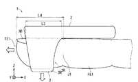
図8から図10は、生体情報測定装置1が指FG1へ装着される様子の一例を模式的に示す図である。図8および図9には、挿入孔3Hに指FG1が挿入されていない状態における生体情報測定装置1の一形態が例示されている。図10には、挿入孔3Hに指FG1が挿入されている状態における生体情報測定装置1の一形態が例示されている。ここでは、本体部2の長手方向としてのX方向に沿って指FG1が延在している状態で該指FG1が装着部3によって挟持される。このとき、本体部2の長手方向と指FG1の延在方向は、完全に一致していなくても良い。例えば、本体部2に対して、指FG1が、Z軸に略平行な仮想的な軸を中心として回転する方向に若干傾けられていても良い。以下、生体情報測定装置1が指FG1へ装着される様子の一例について説明する。<(1-3) Wearing of Biological Information Measuring Device to Finger>
8 to 10 are diagrams schematically illustrating an example of a state in which the biological information measuring device 1 is worn on the finger FG1. 8 and 9 illustrate one form of the biological information measuring device 1 in a state where the finger FG1 is not inserted into the
例えば、図8および図9で示されるように、生体情報測定装置1が指に装着されていない状態では、挿入孔3Hに挿入される指を挟持するための弾性力が装着部3の弾性体によって発せられ、挿入孔3HがZ方向に閉じる方向に環状部3Rが弾性変形している。このとき、例えば、図9で示されるように、環状部3Rが、±Y側の部分B1,B2において折り曲げられた状態となり得る。 For example, as shown in FIGS. 8 and 9, when the biological information measuring device 1 is not attached to the finger, the elastic force for holding the finger inserted into the
これに対し、生体情報測定装置1が指に装着される際には、装着部3の弾性体が発する弾性力に抗して、挿入孔3Hが−Z方向に広げられるように環状部3Rが弾性変形され、図10で示されるように、挿入孔3Hに対して−X方向に指FG1が挿入される。これにより、生体情報測定装置1が指FG1に装着されている状態では、装着部3の弾性体が発する弾性力によって、挿入孔3HをZ方向に閉じる方向に環状部3Rが変形しようとして、指FG1が装着部3によって挟持される。このとき、例えば、挿入孔3Hに挿入された指FG1のうちの爪N1と遠位指節間関節(第1関節とも言う)J1との間の領域に光源部4から発せられる各光Lr,Lirが照射されるように、指FG1が挿入孔3Hに挿入されれば良い。 On the other hand, when the biological information measuring device 1 is attached to the finger, the
ここでは、図10で示されるように、装着部3のX方向における第2長さL3が、指FG1の長手方向(ここではX方向)における先端部TE1から第1関節J1までの長さ(第3長さとも言う)L4よりも短ければ良い。この場合、指FG1の爪N1側(背側)に本体部2が配されれば、本体部2および装着部3の何れによっても、指FG1の第1関節J1が曲げられる動作が阻害され難い。これにより、生体情報測定装置1の指先への装着が容易であり、且つ生体情報測定装置1の長時間の指先への装着による被験者への負担が軽減され得る。 Here, as shown in FIG. 10, the second length L3 in the X direction of the mounting
ここで、指FG1が装着部3に挟持される際に本体部2の長手方向に対して指FG1が配置されるべき位置を示す指標が、本体部2および装着部3の少なくとも一方に設けられていても良い。例えば、図11で示されるように、上記の生体情報測定装置1がベースとされて、指FG1の第1関節J1が配置されるべき位置を示す指標M1が本体部2に設けられた生体情報測定装置1A等が採用されても良い。このような指標M1が設けられれば、指FG1の光を照射すべき位置に素早く生体情報測定装置1Aを装着することができる。すなわち、生体情報測定装置1Aの指FG1への装着に際して、装着位置の位置決めが容易である。また、指FG1の正しい位置に生体情報測定装置1Aが装着されることで、第1関節J1を自由に動かすことができるため、指FG1への負担も軽減される。 Here, an index indicating a position where the finger FG1 is to be disposed with respect to the longitudinal direction of the
<(1−4)一実施形態のまとめ>
以上のように、本実施形態に係る生体情報測定装置1では、光源部4と受光部5とが、装着部3によって指が挟持される際に指が配される領域を挟んで対向している。そして、本体部2の長手方向における該本体部2の第1長さL2が、該長手方向における装着部3の第2長さL3よりも長く、装着部3の中心位置CP3が、本体部2の中心位置CP2から本体部2の長手方向の一端部側にずれている。これにより、生体情報測定装置1の指への装着が容易であり、生体情報測定装置1が指に装着された状態では、装着部3が小型であるために、指の関節が曲げられる動作の妨げとなり難く、さらに指先側に本体部2が突出し難い。したがって、生体情報測定装置1の長時間の指への装着による被験者への負担が軽減され得る。<(1-4) Summary of One Embodiment>
As described above, in the biological information measuring apparatus 1 according to the present embodiment, the
<(2)変形例>
なお、本発明は上述の一実施形態に限定されるものではなく、本発明の要旨を逸脱しない範囲において種々の変更、改良等が可能である。<(2) Modification>
Note that the present invention is not limited to the above-described embodiment, and various modifications and improvements can be made without departing from the gist of the present invention.
例えば、上記一実施形態に係る生体情報測定装置1では、挿入孔3Hが±X方向に貫通していたが、これに限られない。例えば、図12で示されるように、生体情報測定装置1に対して、装着部3のうちの挿入孔3Hの−X方向の一端部側にストッパー部SF1が加えられた生体情報測定装置1Bが採用されても良い。この場合、図13で示されるように、挿入孔3Hに対して+X側から指FG1が挿入されて、ストッパー部SF1に指FG1が十分当接される動作によって、指FG1の光を照射すべき位置に素早く且つ適切に、生体情報測定装置1Aが装着され得る。すなわち、生体情報測定装置1Aの指FG1への装着に際して、装着位置の位置決めが容易である。また、指FG1の正しい位置に生体情報測定装置1Bが装着されることで、第1関節J1を自由に動かすことができるため、指FG1への負担も軽減される。 For example, in the biological information measuring apparatus 1 according to the above-described embodiment, the
ここで、ストッパー部SF1が、ゴム等の弾性を有する部材であれば、挿入孔3Hへ指FG1が挿入される際に、指先が傷つき難いため、生体情報測定装置1Aの指先への装着が容易である。さらに、ストッパー部SF1に指先がフィットし易いため、長時間の指先への生体情報測定装置1Aの装着による被験者への負担が軽減され得る。また、ストッパー部SF1が、光の透過を遮断する遮光部であれば、該遮光部によって外光が受光部5に照射され難い。このため、ノイズによる影響および測定誤差が生じ難い。 Here, if the stopper portion SF1 is a member having elasticity such as rubber, the fingertip is difficult to be damaged when the finger FG1 is inserted into the
また、図14で示されるように、挿入孔3Hが、X方向において一端部側に近づくほど直径が小さくなっている挿入孔3HCに変更された、生体情報測定装置1Cが採用されても良い。ここでは、上記変更に伴って、装着部3および環状部3Rが、装着部3Cおよび環状部3RCに変更される。この場合、挿入孔3HCに対して+X側から指FG1が挿入されて、挿入孔3HCの直径が狭くなっている環状部3Rの部分に指FG1が十分当接される動作によって、指FG1の光を照射すべき位置に素早く且つ適切に、生体情報測定装置1Cが装着され得る。すなわち、上記ストッパー部SF1が設けられた場合と同様に、生体情報測定装置1Cの指FG1への装着に際して、装着位置の位置決めが容易である。 Further, as shown in FIG. 14, a biological information measuring device 1 </ b> C in which the
また、上記一実施形態に係る生体情報測定装置1では、光源部4が、本体部2または装着部3のうちの本体部2側に配されており、受光部5が装着部3に配されていたが、これに限られない。例えば、光源部4が、装着部3に配されており、受光部5が、本体部2または装着部3のうちの本体部2側に配されていても良い。また、例えば、光源部4および受光部5の双方が装着部3に配されていても良い。但し、光源部4への電力供給による電気回路6等に対するノイズの影響を低減する観点から言えば、光源部4が本体部2または装着部3のうちの本体部2側に配されており、受光部5が装着部3に配されている構成が採用されることが好ましい。 Further, in the biological information measuring apparatus 1 according to the above-described embodiment, the
また、上記一実施形態に係る生体情報測定装置1では、表示部が配されていなかったが、これに限られない。例えば、解析処理部623で得られた各種値を表示するための表示部が配されても良い。この場合、通信制御部612および通信部9が省かれても良い。 Moreover, in the biological information measuring device 1 according to the above-described embodiment, the display unit is not arranged, but the present invention is not limited to this. For example, a display unit for displaying various values obtained by the
また、上記一実施形態に係る生体情報測定装置1では、本体部2の一端部に装着部3が固定されていたが、これに限られない。例えば、本体部2が装着部3よりも−X側に若干出っ張った部分を有していても構わない。すなわち、装着部3の中心位置CP3が、本体部2の中心位置CP2から本体部2の長手方向の一端部側にずれていれば良い。 Moreover, in the biological information measuring device 1 according to the above-described embodiment, the mounting
また、上記一実施形態に係る生体情報測定装置1では、指FG1が挿入される環状部3Rを装着部3が備えていたが、これに限られない。例えば、装着部3が指FG1を挟持するクリップ構造を有していても良い。但し、長時間の指への装着による被験者への負担を軽減する観点から言えば、指FG1が挿入される環状部3Rを装着部3が備えている方が好ましい。そして、装着部3が発生する弾性力によって、挿入孔3Hが閉じる方向に環状部3Rが変形する方がより好ましい。 Moreover, in the biological information measuring device 1 according to the above-described embodiment, the mounting
また、上記一実施形態に係る生体情報測定装置1では、信号処理部62によって、血液中の酸素飽和度に係るデジタル値(SpO2値)が取得されたが、これに限られない。例えば、SpO2値が取得されず、心拍数等の脈波等に関する生体の情報が測定されるパルスオキシメータ以外の生体情報測定装置が採用されても良い。Moreover, in the biological information measuring device 1 according to the above-described embodiment, the digital value (SpO2 value) related to the oxygen saturation in the blood is acquired by the
なお、上記一実施形態および各種変形例をそれぞれ構成する全部または一部を、適宜、矛盾しない範囲で組み合わせ可能であることは、言うまでもない。 Needless to say, all or a part of each of the above-described embodiment and various modifications can be combined as appropriate within a consistent range.
1,1A,1B,1C 生体情報測定装置
2 本体部
2h 筐体
3,3C 装着部
3H,3HC 挿入孔
3R,3RC 環状部
4 光源部
5 受光部
6 電気回路
7 電源部
8 充電回路
9 通信部
61 制御部
62 信号処理部
621 電流電圧変換部(I/V変換部)
622 アナログデジタル変換部(A/D変換部)
623 解析処理部
CP2,CP3 中心位置
J1 遠位指節間関節(第1関節)
SF1 ストッパー部
TE1 先端部1, 1A, 1B, 1C Biological
622 Analog-digital converter (A / D converter)
623 Analysis processing unit CP2, CP3 Center position J1 Distal interphalangeal joint (first joint)
SF1 Stopper part TE1 Tip
Claims (22)
Translated fromJapanese該本体部に固定されており且つ生体の指を挟持するための装着部と、
を備え、
前記装着部によって前記指が挟持される際に前記指が配される領域を挟んで対向している光源部と受光部とを含んでおり、
前記本体部は、
信号処理部を含む電気回路と電源部とを有しており、
前記信号処理部は、
前記光源部から発せられて前記指を透過した光が前記受光部で受光されることによって前記受光部から出力される信号から脈波に係るデジタル値を取得し、
前記本体部の長手方向における該本体部の第1長さが、
該長手方向における前記装着部の第2長さよりも長い生体情報測定装置。The main body,
A mounting part that is fixed to the main body part and for holding a living body finger;
With
A light source unit and a light receiving unit facing each other across a region where the finger is arranged when the finger is clamped by the mounting unit;
The main body is
It has an electric circuit including a signal processing unit and a power supply unit,
The signal processing unit
A light value emitted from the light source unit and transmitted through the finger is received by the light receiving unit to obtain a digital value related to a pulse wave from a signal output from the light receiving unit,
The first length of the main body in the longitudinal direction of the main body is
A biological information measuring device longer than a second length of the mounting portion in the longitudinal direction.
前記装着部は、
前記本体部の長手方向に沿って前記指が延在している状態で前記指を挟持するよう設けられている生体情報測定装置。The biological information measuring device according to claim 1,
The mounting part is
The biological information measuring device provided so that the said finger may be clamped in the state where the said finger extends along the longitudinal direction of the main body.
前記装着部の前記長手方向における中心位置が、
前記本体部の前記長手方向における中心位置から前記本体部の前記長手方向における一端部側に向けた一方向にずれている生体情報測定装置。The biological information measuring device according to claim 1 or 2,
The center position in the longitudinal direction of the mounting portion is
The biological information measuring device which has shifted | deviated from the center position in the said longitudinal direction of the said main-body part to one direction toward the one end part side in the said longitudinal direction of the said main-body part.
前記第1長さが、
前記第2長さの2倍以上の長さである生体情報測定装置。The biological information measuring device according to any one of claims 1 to 3, wherein
The first length is
The biological information measuring device having a length that is at least twice as long as the second length.
前記第2長さが、
前記指の先端部から遠位指節間関節までの第3長さよりも短い生体情報測定装置。The biological information measuring device according to any one of claims 1 to 4, wherein
The second length is
The biological information measuring device shorter than the third length from the tip of the finger to the distal interphalangeal joint.
前記指が前記装着部に挟持される際に前記本体部の長手方向に対して前記指が配置されるべき位置を示す指標が設けられている生体情報測定装置。The biological information measuring device according to claim 5,
A biological information measuring device provided with an index indicating a position where the finger is to be arranged with respect to a longitudinal direction of the main body when the finger is held by the mounting portion.
前記装着部が、
前記指を挟持するための弾性力を発する弾性体を含んでいる生体情報測定装置。The biological information measuring device according to any one of claims 1 to 6, wherein
The mounting part is
A biological information measuring device including an elastic body that generates an elastic force for holding the finger.
前記装着部が、
前記指が前記一方向に挿入される挿入孔を有する環状部を含む生体情報測定装置。The biological information measuring device according to any one of claims 1 to 7,
The mounting part is
A biological information measuring device including an annular portion having an insertion hole into which the finger is inserted in the one direction.
前記環状部が、
前記弾性力によって前記挿入孔が閉じる方向に変形する生体情報測定装置。The biological information measuring device according to claim 8,
The annular portion is
A biological information measuring device that deforms in a direction in which the insertion hole is closed by the elastic force.
前記装着部が、
前記挿入孔の前記一方向の一端部側に配されているストッパー部を含む生体情報測定装置。The biological information measuring device according to claim 8 or 9, wherein
The mounting part is
A biological information measuring device including a stopper portion disposed on one end side in the one direction of the insertion hole.
前記ストッパー部が、
遮光部を含む生体情報測定装置。The biological information measuring device according to claim 10,
The stopper part is
A biological information measuring device including a light shielding unit.
前記装着部の前記挿入孔は、前記一方向の一端部側に近づくほど前記挿入孔の直径が小さくなっている生体情報測定装置。The biological information measuring device according to claim 8 or 9, wherein
The biological information measuring device in which the diameter of the insertion hole is smaller as the insertion hole of the mounting portion is closer to one end in the one direction.
前記光源部が、
前記本体部に配されているか、または前記装着部のうちの前記本体部側に配されており、
前記受光部が、
前記装着部に配されている生体情報測定装置。The biological information measuring device according to any one of claims 1 to 12,
The light source unit is
It is arranged on the main body part, or is arranged on the main body part side of the mounting part,
The light receiving unit is
A biological information measuring device arranged in the mounting part.
前記本体部が、
前記装着部よりも硬い筐体を有する生体情報測定装置。The biological information measuring device according to any one of claims 1 to 13,
The main body is
A biological information measuring device having a housing harder than the mounting portion.
前記電源部が、
二次電池を含む生体情報測定装置。The biological information measuring device according to any one of claims 1 to 14,
The power supply unit is
A biological information measuring device including a secondary battery.
前記本体部は、
前記二次電池に対して充電を行うための充電回路をさらに含む生体情報測定装置。The biological information measuring device according to claim 15,
The main body is
The biological information measuring device further includes a charging circuit for charging the secondary battery.
前記充電回路が、
前記二次電池に対する非接触の充電を行うための回路を含む生体情報測定装置。The biological information measuring device according to claim 16,
The charging circuit is
A biological information measuring device including a circuit for performing non-contact charging on the secondary battery.
前記本体部が、
前記信号処理部で取得されるデータを無線方式で送信する通信部をさらに含む生体情報測定装置。The biological information measuring device according to any one of claims 1 to 17,
The main body is
The biological information measuring device further includes a communication unit that transmits data acquired by the signal processing unit in a wireless manner.
前記通信部が、
前記信号処理部で取得される前記脈波に係るデジタル値のデータを送信する生体情報測定装置。The biological information measuring device according to claim 18,
The communication unit is
A biological information measurement device that transmits digital value data related to the pulse wave acquired by the signal processing unit.
前記信号処理部が、
前記脈波に係るデジタル値に基づいて、血液中の酸素飽和度、脈拍数および脈波の間隔のうちの1種以上に係るデジタル値を取得し、
前記通信部が、
前記信号処理部によって取得される前記血液中の酸素飽和度、前記脈拍数および前記脈波の間隔のうちの1種以上に係るデジタル値のデータを送信する生体情報測定装置。The biological information measuring device according to claim 18,
The signal processing unit is
Based on the digital value related to the pulse wave, obtain a digital value related to one or more of oxygen saturation in the blood, pulse rate and pulse wave interval,
The communication unit is
A biological information measuring device that transmits digital value data relating to one or more of oxygen saturation in the blood, the pulse rate, and the pulse wave interval acquired by the signal processing unit.
該本体部に固定されており且つ生体の指を挟持するための装着部と、
を備え、
前記装着部によって前記指が挟持される際に前記指が配される領域を挟んで対向している光源部と受光部とを含んでおり、
前記本体部は、
信号処理部を含む電気回路と電源部とを有しており、
前記信号処理部は、
前記光源部から発せられて前記指を透過した光が前記受光部で受光されることによって前記受光部から出力される信号から、血液中の酵素飽和度に係る値を取得し、
前記本体部の長手方向における該本体部の第1長さが、
該長手方向における前記装着部の第2長さよりも長いパルスオキシメータ。The main body,
A mounting part that is fixed to the main body part and for holding a living body finger;
With
A light source unit and a light receiving unit facing each other across a region where the finger is arranged when the finger is clamped by the mounting unit;
The main body is
It has an electric circuit including a signal processing unit and a power supply unit,
The signal processing unit
The light emitted from the light source unit and transmitted through the finger is received by the light receiving unit, and from the signal output from the light receiving unit, a value related to the degree of enzyme saturation in blood is obtained,
The first length of the main body in the longitudinal direction of the main body is
A pulse oximeter longer than the second length of the mounting portion in the longitudinal direction.
前記装着部は、
前記本体部の長手方向に沿って前記指が延在している状態で前記指を挟持するよう設けられているパルスオキシメータ。The pulse oximeter according to claim 21, wherein
The mounting part is
A pulse oximeter provided to hold the finger in a state where the finger extends along the longitudinal direction of the main body.
Applications Claiming Priority (3)
| Application Number | Priority Date | Filing Date | Title |
|---|---|---|---|
| JP2012176943 | 2012-08-09 | ||
| JP2012176943 | 2012-08-09 | ||
| PCT/JP2013/069463WO2014024653A1 (en) | 2012-08-09 | 2013-07-18 | Biological information measurement device and pulse oximeter |
Publications (1)
| Publication Number | Publication Date |
|---|---|
| JPWO2014024653A1true JPWO2014024653A1 (en) | 2016-07-25 |
Family
ID=50067888
Family Applications (1)
| Application Number | Title | Priority Date | Filing Date |
|---|---|---|---|
| JP2014529406APendingJPWO2014024653A1 (en) | 2012-08-09 | 2013-07-18 | Biological information measuring device and pulse oximeter |
Country Status (3)
| Country | Link |
|---|---|
| US (1) | US20150208967A1 (en) |
| JP (1) | JPWO2014024653A1 (en) |
| WO (1) | WO2014024653A1 (en) |
Families Citing this family (11)
| Publication number | Priority date | Publication date | Assignee | Title |
|---|---|---|---|---|
| US20170086722A1 (en)* | 2014-03-19 | 2017-03-30 | Konica Minolta, Inc. | Biological information measurement device and pulse oximeter |
| JP6536021B2 (en)* | 2014-11-28 | 2019-07-03 | コニカミノルタ株式会社 | Biological information measuring device |
| USD768859S1 (en)* | 2015-08-14 | 2016-10-11 | Hoope Technologies Corporation | Medical appliance |
| JP6914793B2 (en)* | 2017-09-26 | 2021-08-04 | 日本光電工業株式会社 | Probe for pulse photometry |
| CN209595737U (en)* | 2018-12-18 | 2019-11-08 | 安徽华米信息科技有限公司 | The accessory of wearable device and terminal device |
| US11275456B2 (en)* | 2019-09-27 | 2022-03-15 | Apple Inc. | Finger-wearable input assembly for controlling an electronic device |
| WO2021076889A1 (en)* | 2019-10-18 | 2021-04-22 | Trustees Of Dartmouth College | System, apparatus, and method for eyes-free text entry |
| US11733790B2 (en) | 2020-09-24 | 2023-08-22 | Apple Inc. | Ring input device with pressure-sensitive input |
| WO2023195380A1 (en)* | 2022-04-05 | 2023-10-12 | 株式会社ジャパンディスプレイ | Detection device |
| CN118973471A (en)* | 2022-04-05 | 2024-11-15 | 株式会社日本显示器 | Detection device |
| WO2023195393A1 (en)* | 2022-04-05 | 2023-10-12 | 株式会社ジャパンディスプレイ | Detection device |
Citations (5)
| Publication number | Priority date | Publication date | Assignee | Title |
|---|---|---|---|---|
| JPS63192422A (en)* | 1987-02-05 | 1988-08-09 | ヒューレット・パッカード・カンパニー | Medical sensor |
| JPH08224230A (en)* | 1994-12-14 | 1996-09-03 | Ohmeda Inc | Clamp probe housing |
| JP2006239114A (en)* | 2005-03-03 | 2006-09-14 | Citizen Watch Co Ltd | Cuff-less electronic blood pressure monitor |
| JP2008079676A (en)* | 2006-09-26 | 2008-04-10 | Matsushita Electric Works Ltd | Blood flow sensor |
| JP3142046U (en)* | 2008-02-29 | 2008-06-05 | 操 舘野 | Pulse oximeter |
Family Cites Families (3)
| Publication number | Priority date | Publication date | Assignee | Title |
|---|---|---|---|---|
| JP2004159810A (en)* | 2002-11-12 | 2004-06-10 | Otax Co Ltd | Arterial oxygen saturation measuring instrument |
| JP2007117641A (en)* | 2005-10-31 | 2007-05-17 | Konica Minolta Sensing Inc | Biological information measuring apparatus |
| US9179868B2 (en)* | 2010-12-23 | 2015-11-10 | Beijing Choice Electronic Technology Co., Ltd. | Fingerstall oximeter |
- 2013
- 2013-07-18JPJP2014529406Apatent/JPWO2014024653A1/enactivePending
- 2013-07-18USUS14/420,302patent/US20150208967A1/ennot_activeAbandoned
- 2013-07-18WOPCT/JP2013/069463patent/WO2014024653A1/enactiveApplication Filing
Patent Citations (5)
| Publication number | Priority date | Publication date | Assignee | Title |
|---|---|---|---|---|
| JPS63192422A (en)* | 1987-02-05 | 1988-08-09 | ヒューレット・パッカード・カンパニー | Medical sensor |
| JPH08224230A (en)* | 1994-12-14 | 1996-09-03 | Ohmeda Inc | Clamp probe housing |
| JP2006239114A (en)* | 2005-03-03 | 2006-09-14 | Citizen Watch Co Ltd | Cuff-less electronic blood pressure monitor |
| JP2008079676A (en)* | 2006-09-26 | 2008-04-10 | Matsushita Electric Works Ltd | Blood flow sensor |
| JP3142046U (en)* | 2008-02-29 | 2008-06-05 | 操 舘野 | Pulse oximeter |
Also Published As
| Publication number | Publication date |
|---|---|
| WO2014024653A1 (en) | 2014-02-13 |
| US20150208967A1 (en) | 2015-07-30 |
Similar Documents
| Publication | Publication Date | Title |
|---|---|---|
| WO2014024653A1 (en) | Biological information measurement device and pulse oximeter | |
| WO2014024626A1 (en) | Biological information measuring device and pulse oximeter | |
| US20150327809A1 (en) | Biological information measuring device, measuring unit of biological information measuring device, finger accommodating unit of biological information measuring device, and pulse oxymeter | |
| KR102770764B1 (en) | Wearable electronic device and method for detecting contact of living body in wearable electronic device | |
| US5894454A (en) | Portable apparatus | |
| JP3492086B2 (en) | Wrist-mounted pulse wave measuring device and pulse wave information processing device | |
| JP6428761B2 (en) | Biological information measuring device and pulse oximeter | |
| JP2005270543A (en) | Biological information measuring device | |
| US20160166153A1 (en) | Optical communication with optical sensors | |
| JP6881774B2 (en) | Blood flow sensor and blood flow measuring device | |
| JP2015223220A (en) | Bands and electronic equipment | |
| KR100978907B1 (en) | Oxygen Saturation Meter | |
| JP5416626B2 (en) | Motor function measurement sensor, motor function measurement system | |
| WO2014087844A1 (en) | Pulse oximetry system, and subsystem and communication conversion device for constructing said pulse oximetry system | |
| WO2018096864A1 (en) | Portable measuring instrument | |
| JP2002355246A (en) | Accessory for biological light measurement and biological light meter | |
| CN111093496A (en) | Biological information measuring instrument | |
| JP2001276001A (en) | Biological information measuring instrument | |
| US20160128613A1 (en) | Body information sensing device | |
| US12127824B2 (en) | Blood flow measurement device | |
| JP3751127B2 (en) | Carotid artery pressure wave detection device | |
| JP2014008200A (en) | Pulse wave signal processing device, blood pressure measuring apparatus, and pulse wave signal processing program | |
| JP2006000215A (en) | Bioinformation measuring instrument and method | |
| KR102481540B1 (en) | Body foreign substance removal device | |
| KR20220097164A (en) | Device that selectively provides measurement mode and stimulation mode via electrode |
Legal Events
| Date | Code | Title | Description |
|---|---|---|---|
| A131 | Notification of reasons for refusal | Free format text:JAPANESE INTERMEDIATE CODE: A131 Effective date:20160906 | |
| A02 | Decision of refusal | Free format text:JAPANESE INTERMEDIATE CODE: A02 Effective date:20170321 |