JPWO2013145223A1 - Image recognition apparatus, image recognition method, image recognition program, and recording medium - Google Patents
Image recognition apparatus, image recognition method, image recognition program, and recording mediumDownload PDFInfo
- Publication number
- JPWO2013145223A1 JPWO2013145223A1JP2014507189AJP2014507189AJPWO2013145223A1JP WO2013145223 A1JPWO2013145223 A1JP WO2013145223A1JP 2014507189 AJP2014507189 AJP 2014507189AJP 2014507189 AJP2014507189 AJP 2014507189AJP WO2013145223 A1JPWO2013145223 A1JP WO2013145223A1
- Authority
- JP
- Japan
- Prior art keywords
- vibration
- image
- user
- acceleration
- image recognition
- Prior art date
- Legal status (The legal status is an assumption and is not a legal conclusion. Google has not performed a legal analysis and makes no representation as to the accuracy of the status listed.)
- Ceased
Links
Images


Classifications
- G—PHYSICS
- G06—COMPUTING OR CALCULATING; COUNTING
- G06F—ELECTRIC DIGITAL DATA PROCESSING
- G06F3/00—Input arrangements for transferring data to be processed into a form capable of being handled by the computer; Output arrangements for transferring data from processing unit to output unit, e.g. interface arrangements
- G06F3/01—Input arrangements or combined input and output arrangements for interaction between user and computer
- G06F3/017—Gesture based interaction, e.g. based on a set of recognized hand gestures
- B—PERFORMING OPERATIONS; TRANSPORTING
- B60—VEHICLES IN GENERAL
- B60K—ARRANGEMENT OR MOUNTING OF PROPULSION UNITS OR OF TRANSMISSIONS IN VEHICLES; ARRANGEMENT OR MOUNTING OF PLURAL DIVERSE PRIME-MOVERS IN VEHICLES; AUXILIARY DRIVES FOR VEHICLES; INSTRUMENTATION OR DASHBOARDS FOR VEHICLES; ARRANGEMENTS IN CONNECTION WITH COOLING, AIR INTAKE, GAS EXHAUST OR FUEL SUPPLY OF PROPULSION UNITS IN VEHICLES
- B60K35/00—Instruments specially adapted for vehicles; Arrangement of instruments in or on vehicles
- B60K35/10—Input arrangements, i.e. from user to vehicle, associated with vehicle functions or specially adapted therefor
- B—PERFORMING OPERATIONS; TRANSPORTING
- B60—VEHICLES IN GENERAL
- B60K—ARRANGEMENT OR MOUNTING OF PROPULSION UNITS OR OF TRANSMISSIONS IN VEHICLES; ARRANGEMENT OR MOUNTING OF PLURAL DIVERSE PRIME-MOVERS IN VEHICLES; AUXILIARY DRIVES FOR VEHICLES; INSTRUMENTATION OR DASHBOARDS FOR VEHICLES; ARRANGEMENTS IN CONNECTION WITH COOLING, AIR INTAKE, GAS EXHAUST OR FUEL SUPPLY OF PROPULSION UNITS IN VEHICLES
- B60K35/00—Instruments specially adapted for vehicles; Arrangement of instruments in or on vehicles
- B60K35/90—Calibration of instruments, e.g. setting initial or reference parameters; Testing of instruments, e.g. detecting malfunction
- G—PHYSICS
- G06—COMPUTING OR CALCULATING; COUNTING
- G06F—ELECTRIC DIGITAL DATA PROCESSING
- G06F3/00—Input arrangements for transferring data to be processed into a form capable of being handled by the computer; Output arrangements for transferring data from processing unit to output unit, e.g. interface arrangements
- G06F3/01—Input arrangements or combined input and output arrangements for interaction between user and computer
- G06F3/03—Arrangements for converting the position or the displacement of a member into a coded form
- G06F3/0304—Detection arrangements using opto-electronic means
- G—PHYSICS
- G06—COMPUTING OR CALCULATING; COUNTING
- G06F—ELECTRIC DIGITAL DATA PROCESSING
- G06F3/00—Input arrangements for transferring data to be processed into a form capable of being handled by the computer; Output arrangements for transferring data from processing unit to output unit, e.g. interface arrangements
- G06F3/01—Input arrangements or combined input and output arrangements for interaction between user and computer
- G06F3/03—Arrangements for converting the position or the displacement of a member into a coded form
- G06F3/041—Digitisers, e.g. for touch screens or touch pads, characterised by the transducing means
- G06F3/042—Digitisers, e.g. for touch screens or touch pads, characterised by the transducing means by opto-electronic means
- G06F3/0425—Digitisers, e.g. for touch screens or touch pads, characterised by the transducing means by opto-electronic means using a single imaging device like a video camera for tracking the absolute position of a single or a plurality of objects with respect to an imaged reference surface, e.g. video camera imaging a display or a projection screen, a table or a wall surface, on which a computer generated image is displayed or projected
- G—PHYSICS
- G06—COMPUTING OR CALCULATING; COUNTING
- G06F—ELECTRIC DIGITAL DATA PROCESSING
- G06F3/00—Input arrangements for transferring data to be processed into a form capable of being handled by the computer; Output arrangements for transferring data from processing unit to output unit, e.g. interface arrangements
- G06F3/01—Input arrangements or combined input and output arrangements for interaction between user and computer
- G06F3/048—Interaction techniques based on graphical user interfaces [GUI]
- G06F3/0481—Interaction techniques based on graphical user interfaces [GUI] based on specific properties of the displayed interaction object or a metaphor-based environment, e.g. interaction with desktop elements like windows or icons, or assisted by a cursor's changing behaviour or appearance
- G06F3/04817—Interaction techniques based on graphical user interfaces [GUI] based on specific properties of the displayed interaction object or a metaphor-based environment, e.g. interaction with desktop elements like windows or icons, or assisted by a cursor's changing behaviour or appearance using icons
- B—PERFORMING OPERATIONS; TRANSPORTING
- B60—VEHICLES IN GENERAL
- B60K—ARRANGEMENT OR MOUNTING OF PROPULSION UNITS OR OF TRANSMISSIONS IN VEHICLES; ARRANGEMENT OR MOUNTING OF PLURAL DIVERSE PRIME-MOVERS IN VEHICLES; AUXILIARY DRIVES FOR VEHICLES; INSTRUMENTATION OR DASHBOARDS FOR VEHICLES; ARRANGEMENTS IN CONNECTION WITH COOLING, AIR INTAKE, GAS EXHAUST OR FUEL SUPPLY OF PROPULSION UNITS IN VEHICLES
- B60K2360/00—Indexing scheme associated with groups B60K35/00 or B60K37/00 relating to details of instruments or dashboards
- B60K2360/146—Instrument input by gesture
- B—PERFORMING OPERATIONS; TRANSPORTING
- B60—VEHICLES IN GENERAL
- B60K—ARRANGEMENT OR MOUNTING OF PROPULSION UNITS OR OF TRANSMISSIONS IN VEHICLES; ARRANGEMENT OR MOUNTING OF PLURAL DIVERSE PRIME-MOVERS IN VEHICLES; AUXILIARY DRIVES FOR VEHICLES; INSTRUMENTATION OR DASHBOARDS FOR VEHICLES; ARRANGEMENTS IN CONNECTION WITH COOLING, AIR INTAKE, GAS EXHAUST OR FUEL SUPPLY OF PROPULSION UNITS IN VEHICLES
- B60K2360/00—Indexing scheme associated with groups B60K35/00 or B60K37/00 relating to details of instruments or dashboards
- B60K2360/20—Optical features of instruments
- B60K2360/21—Optical features of instruments using cameras
- G—PHYSICS
- G06—COMPUTING OR CALCULATING; COUNTING
- G06F—ELECTRIC DIGITAL DATA PROCESSING
- G06F2203/00—Indexing scheme relating to G06F3/00 - G06F3/048
- G06F2203/041—Indexing scheme relating to G06F3/041 - G06F3/045
- G06F2203/04108—Touchless 2D- digitiser, i.e. digitiser detecting the X/Y position of the input means, finger or stylus, also when it does not touch, but is proximate to the digitiser's interaction surface without distance measurement in the Z direction
Landscapes
- Engineering & Computer Science (AREA)
- General Engineering & Computer Science (AREA)
- Theoretical Computer Science (AREA)
- Human Computer Interaction (AREA)
- Physics & Mathematics (AREA)
- General Physics & Mathematics (AREA)
- Transportation (AREA)
- Chemical & Material Sciences (AREA)
- Combustion & Propulsion (AREA)
- Mechanical Engineering (AREA)
- Multimedia (AREA)
- User Interface Of Digital Computer (AREA)
- Navigation (AREA)
- Image Analysis (AREA)
Abstract
Translated fromJapaneseDescription
Translated fromJapanese本発明は、カメラで撮像した画像中の認識対象物の位置を認識する画像認識装置、画像認識方法、画像認識プログラム、及び記録媒体に関する。 The present invention relates to an image recognition apparatus, an image recognition method, an image recognition program, and a recording medium for recognizing the position of a recognition target in an image captured by a camera.
近年では、カメラで撮像した画像中の所定の認識対象物の位置を認識する画像認識技術が多く提案されている。この位置認識を高い精度で行うためには、カメラが受ける振動に対して撮像画像の補正などを行う十分な対策を講じる必要がある。 In recent years, many image recognition techniques for recognizing the position of a predetermined recognition target in an image captured by a camera have been proposed. In order to perform this position recognition with high accuracy, it is necessary to take sufficient measures to correct the captured image with respect to vibrations received by the camera.
これに対して例えば特許文献1に記載の技術では、カメラで撮影した画像のうちの背景の移動ベクトルを検出し、この逆ベクトルで光軸シフトレンズを動かすことでユーザの手ぶれに対する補正を行い、被写体のぶれない流し撮りを可能にする。 On the other hand, for example, in the technique described in
一方近年では、車両等の移動体に搭載するインターフェースデバイスに対しての操作入力方法として、例えば当該インターフェースデバイスが備えるカメラの前でユーザが掲げた手の位置を画像認識し、その位置に対応する選択指示を入力するジェスチャー操作入力技術が提案されている。ここで当該移動体の走行に伴う振動の発生によって画像認識される手の位置にも振動(ぶれ)が生じるが、この場合の振動にはカメラを含むインターフェースデバイス自体と移動体との間の相対的な振動以外にも、ユーザの身体自体と移動体との間の相対的な振動も合成されて含まれている。 On the other hand, in recent years, as an operation input method for an interface device mounted on a moving body such as a vehicle, for example, the position of a hand raised by a user in front of a camera included in the interface device is image-recognized, and the position corresponds A gesture operation input technique for inputting a selection instruction has been proposed. Here, vibration (shake) is also generated in the position of the hand recognized as an image due to the generation of vibration accompanying the traveling of the moving body. In this case, the vibration between the interface device including the camera itself and the moving body In addition to general vibration, a relative vibration between the user's body itself and the moving body is also synthesized and included.
上記従来技術では、カメラ自体と移動体との間の相対的な振動に対する補正は可能であるが、ユーザの身体自体と移動体との間の相対的な振動に対しては何ら対処できない。このため、移動体に搭載されたカメラの撮像画像により当該移動体に搭乗するユーザの所定の身体部分を位置認識する際の認識精度を向上できる技術が要望されていた。 Although the above-described conventional technology can correct the relative vibration between the camera itself and the moving body, it cannot deal with the relative vibration between the user's body itself and the moving body. For this reason, there has been a demand for a technique that can improve the recognition accuracy when recognizing the position of a predetermined body part of a user who rides on the moving body from a captured image of a camera mounted on the moving body.
本発明が解決しようとする課題には、上記した問題が一例として挙げられる。 The problem to be solved by the present invention includes the above-described problem as an example.
上記課題を解決するために、請求項1記載の発明は、移動体に配置されて当該移動体に搭乗するユーザの画像を撮像する撮像手段と、前記撮像手段に付加される加速度を検出する加速度検出手段と、前記加速度に基づいて、前記移動体と前記ユーザとの間の相対的な連成振動を検出する連成振動検出手段と、前記撮像手段によって撮像された前記画像と、前記連成振動とに基づいて、前記ユーザの所定の身体部分の位置を認識する認識手段と、を備える。 In order to solve the above-mentioned problem, the invention described in
上記課題を解決するために、請求項7記載の発明は、画像認識方法であって、移動体に配置された撮像手段で当該移動体に搭乗するユーザの画像を撮像する撮像工程と、前記撮像手段に付加される加速度を検出する加速度検出工程と、前記加速度に基づいて、前記移動体と前記ユーザとの間の相対的な連成振動を検出する連成振動検出工程と、前記撮像工程で撮像された前記画像と、前記連成振動とに基づいて、前記ユーザの所定の身体部分の位置を認識する認識工程と、を実行する。 In order to solve the above-mentioned problem, an invention according to claim 7 is an image recognition method, wherein an imaging step of imaging an image of a user who rides on the moving body with an imaging means arranged on the moving body, and the imaging An acceleration detecting step for detecting an acceleration applied to the means, a coupled vibration detecting step for detecting a relative coupled vibration between the moving body and the user based on the acceleration, and the imaging step. A recognition step of recognizing the position of the predetermined body part of the user based on the captured image and the coupled vibration is executed.
上記課題を解決するために、請求項8記載の発明は、画像認識プログラムであって、請求項7に記載の画像認識方法を、画像認識装置により実行させる。 In order to solve the above-mentioned problem, the invention described in claim 8 is an image recognition program, and causes the image recognition apparatus to execute the image recognition method described in claim 7.
上記課題を解決するために、請求項9記載の発明は、記録媒体であって、請求項8に記載の画像認識プログラムが、前記画像認識装置により読み取り可能に記憶されている。 In order to solve the above-mentioned problem, the invention according to claim 9 is a recording medium, and the image recognition program according to claim 8 is stored so as to be readable by the image recognition apparatus.
以下、本発明の実施形態のうちの一つを図面を参照しつつ説明する。 Hereinafter, one of the embodiments of the present invention will be described with reference to the drawings.
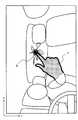
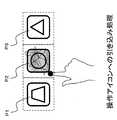
図1は、本発明の画像認識装置の実施形態を含むナビゲーション装置を用いたジェスチャー操作入力の一例を示す斜視図である。この図1において、ナビゲーション装置Sは、移動体である車両Vのハンドル101や計器類102の横にインターフェースデバイス1を固定的に設けている。この例のインターフェースデバイス1は全体が矩形の平板状で形成されており、その前面にはディスプレイ2とデバイスカメラ3が備えられている。 FIG. 1 is a perspective view showing an example of gesture operation input using a navigation device including an embodiment of an image recognition device of the present invention. In FIG. 1, the navigation apparatus S is provided with an
図示する例では、当該ナビゲーション装置Sに対する各種操作に対応した3つの操作アイコンP1,P2,P3がディスプレイ上に横一列に並んで表示されている。運転席(又は助手席)にいるユーザはディスプレイ2上に直接触れずともその表示位置の手前側の空間を人差し指で指し示すだけで、ナビゲーション装置Sはデバイスカメラ3を介してその指先の位置をリアルタイムに画像認識し、ディスプレイ2上の対応する位置に指示点Mをポインティングマーカとして表示する。そして指示点Mが一定時間静止した際には、その時点で指示点Mが位置するいずれかの操作アイコン(図示する例では操作アイコンP2)が選択操作されたとして検知する。 In the illustrated example, three operation icons P1, P2, and P3 corresponding to various operations on the navigation device S are displayed side by side on the display. The user in the driver's seat (or passenger seat) does not touch the
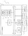
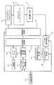
図2は、ナビゲーション装置Sのハードウェア構成例を示すブロック図である。この図2において、ナビゲーション装置Sは、インターフェースデバイス1と、ナビゲーション装置本体5を有している。 FIG. 2 is a block diagram illustrating a hardware configuration example of the navigation device S. As illustrated in FIG. In FIG. 2, the navigation device S includes an
インターフェースデバイス1は、上述したディスプレイ2とデバイスカメラ3の他にX−Y加速度センサ4も内部に備えている。 The
ディスプレイ2は、例えばLCDパネルなどで構成されて、ナビゲーション装置本体5のグラフィックコントローラ(後述)から入力された画像信号に基づき、各種の情報画面を表示する機能を有する。 The
デバイスカメラ3は撮像手段に相当し、例えばCCD撮像素子などを利用し、上述した当該車両Vの室内で主に運転席側と助手席側の中間方向へ向けて(もしくはその周囲を回動可能に)画像を撮像し、対応する信号をナビゲーション装置本体5のCPU(後述)へ出力する機能を有する。なお、このデバイスカメラ3は十分に短い時間周期で時系列的に複数の画像フレームを撮像し続けることで、室内画像を動画の形式で撮像する。また、上記図1に示したジェスチャー操作入力が可能なように、デバイスカメラ3はその撮像方向が上記ディスプレイ2の表示方向とほぼ同じ方向に向かうようインターフェースデバイス1に固定されている。 The device camera 3 corresponds to an image pickup means, and uses, for example, a CCD image pickup device or the like, and can turn around the driver seat side and the passenger seat side in the interior of the vehicle V described above (or around it). B) a function of capturing an image and outputting a corresponding signal to a CPU (described later) of the
X−Y加速度センサ4は、例えばピエゾ抵抗型のMEMS素子などを利用し、デバイスカメラ3の後述する撮像領域X−YのX方向とY方向にそれぞれ対応する2軸で、当該デバイスカメラ3に付加された加速度を検出する機能を有する。 The XY acceleration sensor 4 uses, for example, a piezoresistive MEMS element or the like, and has two axes corresponding respectively to an X direction and a Y direction of an imaging region XY, which will be described later, of the device camera 3. It has a function of detecting the added acceleration.
ナビゲーション装置本体5は、CPU11、記憶装置12、GPS13、グラフィックコントローラ14を有している。 The
CPU11は、所定のプログラムの動作によって各種の演算を行うとともに、他の各部との間で情報の交換や各種の制御指示を出力することで、ナビゲーション装置S全体を制御する機能を有する。 The
記憶装置12は、ROM12a、RAM12b、及び記憶媒体12cを有する。ROM12aは、各種の処理プログラムやその他必要な情報が予め書き込まれた情報記憶媒体である。RAM12bは、上記各種のプログラムを実行する上で必要な情報の書き込み及び読み出しが行われる情報記憶媒体である。記憶媒体12cは、例えばフラッシュメモリ、ハードディスクなどの不揮発性の情報記憶媒体であり、後述するような加速度と連成振動との間の対応関係を記憶する。この記憶媒体12cが各請求項記載の記憶部に相当する。 The
GPS13は、車両Vの現在地の測位を行い現在位置情報を取得する。当該取得された情報を用いて、ナビゲーション装置Sは、予め記憶している地図情報に基づいて上記現在位置の周辺の地形、道路、及び施設等の情報を取得することができる。 The
グラフィックコントローラ14は、CPU11の制御によってビデオRAM(図示せず)及び上記GPS13などから画像データを取得し、この画像データに基づく画像信号を上記ディスプレイ2に表示させる機能を有する。 The
以上の構成のナビゲーション装置Sにおいては、当該車両Vに搭乗するユーザを含めた室内画像をデバイスカメラ3で動画形式で撮像し、各画像フレーム毎でユーザの手H(ユーザの所定の身体部分に相当)の形状と位置を画像認識する。例えば、図3に示す例のように、デバイスカメラ3が撮像した室内画像の撮像座標X−Y上においてユーザの人差し指の指先の位置を画像認識で検出し、その位置をその時点でユーザにより指し示されている指示点Mとして検出する。ここで、当該車両Vの走行に伴って車両V全体が振動した際には、上記指示点Mもユーザが意図しない振れ方向と振れ幅で振動してしまう。しかし、この指示点Mの振れ方向と振れ幅については、上記X−Y加速度で検出したX方向とY方向それぞれの加速度と一定の対応関係があることから、装置側で振動に対応した位置補正を行ってユーザが本来意図していると推測される指示点Mを検出することが可能である。この位置補正の手法について以下に詳細に説明する。 In the navigation device S configured as described above, a room image including a user boarding the vehicle V is captured in a moving image format by the device camera 3, and the user's hand H (on a predetermined body part of the user) is captured for each image frame. Equivalent) shape and position. For example, as shown in FIG. 3, the position of the fingertip of the user's index finger is detected by image recognition on the imaging coordinates XY of the indoor image captured by the device camera 3, and the position is pointed to by the user at that time. The indicated point M is detected. Here, when the vehicle V as a whole vibrates as the vehicle V travels, the indicated point M also vibrates with a shake direction and a shake width that are not intended by the user. However, since there is a fixed correspondence between the acceleration in the X direction and the Y direction detected by the XY acceleration, the position correction corresponding to the vibration on the apparatus side with respect to the vibration direction and the vibration width of the indication point M. It is possible to detect the pointing point M that is presumed to be originally intended by the user. This position correction method will be described in detail below.
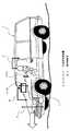
まず、図4を参照して指示点Mの振動を構成する2種類の振動について説明する。なお以下の説明においては、ユーザは意図的にその手を動かさず静止させたままの状態を維持していることを前提とする。この図4において、例えば車両Vが凹凸のある路面上を走行することで、車両V全体に1次的な直接振動Aが発生する。 First, with reference to FIG. 4, two types of vibration constituting the vibration of the designated point M will be described. In the following description, it is assumed that the user intentionally maintains a stationary state without moving his hand. In FIG. 4, for example, when the vehicle V travels on an uneven road surface, primary direct vibration A is generated in the entire vehicle V.
本実施形態の例では、デバイスカメラ3とX−Y加速度センサ4を備えたインターフェースデバイス1が車両Vに固定的に設置されているため、上記直接振動Aに含まれる低周波成分に対しては当該インターフェースデバイス1自体と車両Vとの間で相対的な振動はほとんど発生しない。しかし、エンジンの振動や上記直接振動Aに含まれる高周波成分などに対しては、当該インターフェースデバイス1自体と車両Vとの間で2次的な相対振動Bが生じてしまう。 In the example of this embodiment, since the
また一方、運転手や同乗者であるユーザの身体はシートベルトによる多少の拘束があるものの車両Vのシート上に着座しているだけであるため、上記直接振動Aによりユーザの身体自体が振動しやすく、またそのユーザの身体のうちでもインターフェースデバイス1の前方に掲げたユーザの手の部分は梁の先端部に相当して相対的に揺れやすい。つまり、上記直接振動Aの影響を受けてユーザの手の部分と車両Vとの間で2次的な相対振動Cが生じやすい。 On the other hand, the body of the user who is a driver or a passenger is only seated on the seat of the vehicle V although there is some restraint by the seat belt, so the user's body itself vibrates due to the direct vibration A. In addition, the user's hand held in front of the
インターフェースデバイス1に備えられたX−Y加速度センサ4には、上記直接振動Aと相対振動Bとを合成した振動A+Bによる加速度が検出される。またユーザの手の部分は、上記直接振動Aと相対振動Cとを合成した振動A+Cが生じる。しかし、上記の直接振動A、相対振動A+B、A+Cはいずれも路面を基準とした対地振動であり、それに対して本実施形態で補正すべき振動はデバイスカメラ3の撮像座標X−Y中におけるユーザの手の振動、つまりデバイスカメラ3とユーザの手との間の相対振動B+Cである。このため、路面基準の対地振動ではなく、車両基準の対車振動で相対振動Bと相対振動Cを検出してそれぞれ補正できれば、共通の車両V上で受ける直接振動Aの影響は無視できる。以下においては、上記の相対振動Bを装置振動、相対振動Cを連成振動として区別する。 The XY acceleration sensor 4 provided in the
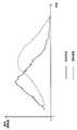
図5は、上記装置振動と上記連成振動のそれぞれの特性を説明する図の一例である。図示する例では、車両Vに例えばY方向(上下方向)でインパルスモデル振動(瞬間的な単位振動量だけの振動:図示省略)を加振した後に生じる装置振動と連成振動のY方向成分の振り幅の時間変化を比較して示している。 FIG. 5 is an example of a diagram illustrating the characteristics of the apparatus vibration and the coupled vibration. In the example shown in the figure, the Y direction component of the device vibration and the combined vibration generated after applying the impulse model vibration (vibration with an instantaneous unit vibration amount: not shown) to the vehicle V in the Y direction (vertical direction), for example. The change with time of the amplitude is shown in comparison.
インパルスモデル振動の加振後にはまず先に装置振動(実線部参照)が発生し、その後所定の時間差で重複して連成振動(破線部参照)が発生する。いずれも山形の波形で振動するが、それぞれのピークタイミングにも発生時の時間差に対応したズレが生じている。これは、車両の構造部材で固定されているインターフェースデバイス1の方が早く装置振動を伝達し、柔軟なユーザの身体を介して伝達する連成振動の方が遅れて発生するためである。 After the impulse model vibration is vibrated, the apparatus vibration (see the solid line portion) is first generated, and then the coupled vibration (see the broken line portion) is overlapped with a predetermined time difference. Each of them vibrates with a mountain-shaped waveform, but a deviation corresponding to the time difference at the time of occurrence occurs at each peak timing. This is because the
また装置振動の場合には、所定の加振条件に対して装置振動の振動量や振動の発生タイミング及びピークタイミングは常に同じ対応関係で発生する。このため本実施形態においては、X−Y加速度センサ4で検出した2軸の加速度と、その発生前後における画像フレーム間での車両Vの室内背景の移動偏差(動きベクトル)とに基づいて直接的に装置振動を推定できる。この移動偏差は、撮像座標X−Y上で画像認識により検出された車両Vの所定部分の認識位置の偏差で求めるといった公知の手法を用いればよく、ここでは詳しい説明を省略する。この場合、X−Y加速度センサ4で検出される2軸の加速度にはそれぞれ上記の直接振動Aも含まれるが、上記移動偏差の検出を開始するトリガーとして用いるため各加速度の大きさは問題としない。 In the case of device vibration, the vibration amount of the device vibration, the generation timing of the vibration, and the peak timing are always generated in the same correspondence with a predetermined excitation condition. For this reason, in this embodiment, it is directly based on the biaxial acceleration detected by the XY acceleration sensor 4 and the movement deviation (motion vector) of the indoor background of the vehicle V between the image frames before and after the occurrence. The device vibration can be estimated. The movement deviation may be obtained by using a known method such as obtaining the deviation of the recognition position of a predetermined portion of the vehicle V detected by image recognition on the imaging coordinates XY, and detailed description thereof is omitted here. In this case, the biaxial acceleration detected by the XY acceleration sensor 4 also includes the direct vibration A, but the magnitude of each acceleration is problematic because it is used as a trigger for starting the detection of the movement deviation. do not do.
一方、連成振動の場合には加振条件が同じであっても、当該ユーザの身体各部(例えば腕など)の重量や関節の柔軟さなどといった多様な個人的条件によって、その振り幅(振動量に相当)や振動の発生タイミング、ピークタイミング(振動タイミングに相当)が異なってくる。これに対して本実施形態では、その時点で当該ナビゲーション装置Sを使用するユーザを予め設定しておき、X−Y加速度センサ4で検出される加速度と連成振動との対応関係を解析して記憶することでそのユーザに対応した連成振動の特性を学習する。そしてそのユーザに対する学習練度が十分である場合には、上記X−Y加速度センサで検出された加速度を学習結果に照合することで、ユーザに対応する連成振動を高い精度で検出できる。なお本実施形態の例では、連成振動の振り幅は、撮像座標X−Y上におけるそのときの指示点Mと操作アイコンP1、P2、P3の中心位置(撮像座標中の所定位置に相当)との間の離間距離(偏差に相当)で検出する。またこの場合も、X−Y加速度センサ4で検出される2軸の加速度にはそれぞれ上記の直接振動Aも含まれているが、直接振動Aと連成振動(相対振動C)は比例関係にあり、上記学習では加速度と連成振動との間の対応関係(例えば係数)を記憶するため問題はない。 On the other hand, in the case of coupled vibration, even if the excitation conditions are the same, the swing width (vibration) depends on various personal conditions such as the weight of each part of the user's body (eg, arm) and the flexibility of the joint. (Corresponding to the amount), vibration generation timing, and peak timing (corresponding to vibration timing) differ. On the other hand, in this embodiment, a user who uses the navigation device S at that time is set in advance, and the correspondence relationship between the acceleration detected by the XY acceleration sensor 4 and the coupled vibration is analyzed. The characteristic of the coupled vibration corresponding to the user is learned by memorizing. And when the learning skill level with respect to the user is sufficient, the coupled vibration corresponding to the user can be detected with high accuracy by comparing the acceleration detected by the XY acceleration sensor with the learning result. In the example of the present embodiment, the amplitude of the coupled vibration is the center position of the indication point M and the operation icons P1, P2, and P3 at that time on the imaging coordinates XY (corresponding to a predetermined position in the imaging coordinates). Is detected by a separation distance (corresponding to a deviation) between and. Also in this case, the biaxial acceleration detected by the XY acceleration sensor 4 includes the direct vibration A, but the direct vibration A and the coupled vibration (relative vibration C) are in a proportional relationship. In the learning, there is no problem because the correspondence (for example, coefficient) between the acceleration and the coupled vibration is stored.
例えば図6(a)に示すように 振動に対して何ら補正を行わない場合には、指示点Mは実線で示す装置振動と破線で示す連成振動を合成した振動で大きく振れる。これに対して、上記公知の手法により検出した装置振動に対応して撮像画像の位置補正を行った場合には、図6(b)に示すように破線で示す連成振動だけで指示点Mが振動する。そして本実施形態では、さらに上記学習により検出したユーザ別の連成振動に対しても併せて撮像画像の位置補正を行うことで、図6(c)に示すように指示点Mの振動を大幅に抑えることができる。以上のように、装置振動と連成振動の両方に対応して撮像画像の位置補正を行うことで、ユーザが本来意図している指示点Mを高い精度で推定できる。 For example, as shown in FIG. 6A, when no correction is performed on the vibration, the indication point M is greatly shaken by a vibration obtained by synthesizing the device vibration indicated by the solid line and the coupled vibration indicated by the broken line. On the other hand, when the position of the captured image is corrected corresponding to the apparatus vibration detected by the known method, the indication point M is obtained only by the coupled vibration indicated by the broken line as shown in FIG. Vibrates. In the present embodiment, the vibration of the indication point M is greatly increased as shown in FIG. 6C by correcting the position of the captured image in conjunction with the user-specific coupled vibration detected by the learning. Can be suppressed. As described above, by performing position correction of the captured image corresponding to both the apparatus vibration and the coupled vibration, the instruction point M originally intended by the user can be estimated with high accuracy.
図7は、上述した位置補正の手法を利用した上記ジェスチャー操作入力に関係するソフトウェア構成例を示すブロック図である。この図7において、ジェスチャー操作入力に関係するソフトウェアブロックとしては、撮像部21、フレームバッファ22、加速度検出部23、ブロック別動きベクトル検出部24、装置振動補正量算出部25、指示点ずれ量検出部26、連成振動補正量算出部27、画像補正処理部28、画像認識処理部29、ハンドジェスチャーインターフェース30、グラフィックユーザインターフェース31、差分量算出部32、ユーザ別特性学習部33を有している。 FIG. 7 is a block diagram illustrating a software configuration example related to the gesture operation input using the position correction method described above. In FIG. 7, the software blocks related to the gesture operation input include the
撮像部21は、デバイスカメラ3の撮像方向に対応する撮像座標X−Yで画像フレーム単位の撮像をハードウェア的に行う。 The
フレームバッファ22は、撮像部21で撮像された各画像フレームを時系列順に記憶する。 The
加速度検出部23は、X−Y加速度センサ4でのX方向、Y方向それぞれにおける加速度の検出をハードウェア的に行う。 The
ブロック別動きベクトル検出部24は、画像フレームをブロック分割したうちで明らかに車両Vの所定部分(例えばヘッドレストなど)であるとして画像認識されたブロック部分の位置について、所定量以上の振動に対応する加速度の検出前と検出後の画像フレーム間での移動偏差を動きベクトルとして検出する。この動きベクトルの検出処理は、公知の振動に対する画像位置補正の技術を用いて行えばよく、ここでは詳しい説明を省略する。 The block-by-block motion
装置振動補正量算出部25は、上記ブロック別動きベクトル検出部24で検出した動きベクトルの逆ベクトルに基づいて、撮像座標X−Yに対応する装置振動分の画像フレームの位置補正量を算出する。 The apparatus vibration correction
指示点ずれ量検出部26は、後に詳述するユーザ別特性学習部33で学習したユーザ別の連成振動の特性を参照し、上記加速度検出部23で検出した加速度に対応する連成振動を指示点Mの座標ずれ量として検出する。 The pointing point deviation
連成振動補正量算出部27は、上記指示点ずれ量検出部26で検出した指示点Mの座標ずれ量に基づいて、撮像座標X−Yに対応する装置振動分の画像フレームの位置補正量を算出する。 The coupled vibration correction
画像補正処理部28は、上記装置振動補正量算出部25で算出した装置振動分の補正量と、上記連成振動補正量算出部27で算出した連成振動分の補正量とを加算して最終的な実効補正量を算出し、上記フレームバッファ22から読み出した対応するタイミングの画像フレームに対して撮像座標X−Yでの位置補正を行う。 The image
画像認識処理部29は、上記画像補正処理部28で位置補正した画像フレームにおいて、その撮像座標X−Yにおけるユーザの手及びヘッドレストなどの車両部分の形状と位置を画像認識する。 The image
ハンドジェスチャーインターフェース30は、上記画像認識処理部29の認識結果に基づいて指示点Mの位置を認識し、その時点でユーザが意図しているディスプレイ2上の指示位置を推定する。 The
グラフィックユーザインターフェース31は、その時点でディスプレイ2に表示している操作アイコンP1、P2、P3の配置と、上記ハンドジェスチャーインターフェース30が推定した指示位置に基づいて、ユーザが選択しようとしている操作アイコンP1、P2、P3を判定する。 The
差分量算出部32は、その時点の指示点Mの位置と、上記グラフィックユーザインターフェース31で選択対象として判定した操作アイコンP1、P2、P3の中心位置との間の離間距離を差分量として算出する。 The difference
ユーザ別特性学習部33は、上記差分量算出部32で算出した差分量を連成振動の振り幅とみなし、これとX−Y加速度センサ4で検出される加速度との対応関係を解析して上記記憶媒体12cに記憶させることでその時点のユーザに対応した連成振動の特性を学習する。 The user-specific
以上のソフトウェア構成によるジェスチャー操作入力では、フレームバッファ22に記憶される各画像フレームに対し、装置振動補正量算出部25が算出する装置振動分の補正量と、連成振動補正量算出部27が算出する連成振動分の補正量とを併せて各画像フレームの撮像タイミングに対応した撮像座標X−Yに対する位置補正が可能となる。この位置補正は、例えば上記図3に対応する図8に示すように、元の撮像座標X−Yに対して画像フレーム全体の位置を補正する。そして特に図示しないが、このように位置補正された画像フレームを撮像順に切り替えて見ると、指示点Mの位置が安定する。つまり、ユーザが意図的に指示点Mの静止状態を維持したつもりでありながら実際にはユーザの手が不可抗力的に連成振動している場合であっても、ナビゲーション装置S側でその連成振動に対応して指示点Mの位置を安定化できる。 In the gesture operation input with the above software configuration, the correction amount for the device vibration calculated by the device vibration correction
なお上記図8のソフトウェアブロック図において、上記撮像部21が、各請求項記載の撮像工程に相当する。また、上記加速度検出部23が、各請求項記載の加速度検出手段及び加速度検出工程に相当する。また、上記指示点ずれ量検出部26と、上記連成振動補正量算出部27が、各請求項記載の連成振動検出手段及び連成振動検出工程に相当し、上記差分量算出部32と上記ユーザ別特性学習部33が各請求項記載の学習手段に相当する。また、上記画像補正処理部28が、各請求項記載の補正手段及び補正工程に相当する。また、上記画像認識処理部29が、各請求項記載の認識手段及び認識工程に相当する。また、上記ブロック別動きベクトル検出部24と上記装置振動補正量算出部25が、各請求項記載の装置振動検出手段に相当する。 In the software block diagram of FIG. 8, the
また本実施形態では、図9に示すような指示点Mの操作アイコンP1、P2、P3への引き込み処理を行う。これは、ディスプレイ2上で隣接する操作アイコンP1、P2、P3どうしが離間して表示されている場合でも、アイコン間の中間位置まで各操作アイコンP1、P2、P3に対応する指示点Mの判定有効領域を広げて設定している。これにより、図示するように指示点Mが振動によって各操作アイコンP2の表示領域から一時的にずれ出てしまった場合でも、当該操作アイコンP2の選択状態を維持できる。この引き込み処理は、例えばユーザの任意の時間だけアイコンの選択状態を維持し続ける必要のある操作に対して有効である。また、操作アイコンP1、P2、P3の選択状態を長く維持できることから、連成振動の学習状態も長く維持できる点で有効である。 In the present embodiment, the process of drawing the designated point M into the operation icons P1, P2, and P3 as shown in FIG. 9 is performed. This is because even when the adjacent operation icons P1, P2, and P3 are displayed on the
図10は、以上説明した動作態様を実現するために、ナビゲーション装置本体5のCPU11が実行する制御内容を表すフローチャートの一例である。なお、このフローは、デバイスカメラ3が動画の形態で室内画像を撮像している間に、例えば上記グラフィックユーザインターフェースがジェスチャー操作入力を要求した際に呼び出されて実行する。また、このフローを実行する前には、予め登録したユーザのうちのいずれのユーザが今回ジェスチャー操作入力するかを設定しておく必要がある。 FIG. 10 is an example of a flowchart showing the control content executed by the
図10において、まずステップS5において、デバイスカメラ3で室内画像を1画像フレームだけ撮像する。 In FIG. 10, first, in step S <b> 5, an indoor image is captured by the device camera 3 for only one image frame.
ステップS10へ移り、X−Y加速度センサ4でX方向とY方向の2軸で加速度を検出する。 Proceeding to step S10, the X-Y acceleration sensor 4 detects acceleration on two axes in the X and Y directions.
ステップS100へ移り、上記ステップS5で撮像した画像フレームに対し、上記ステップS10で検出した加速度に基づいて撮像座標X−Yにおける位置補正を行う画像位置補正処理を実行する。 Proceeding to step S100, an image position correction process is executed for correcting the position at the imaging coordinates XY based on the acceleration detected at step S10 on the image frame captured at step S5.
ステップS200へ移り、上記ステップS100で位置補正された画像フレームにおいてユーザの手を画像認識する画像認識処理を実行する。なお、上記ステップS100とこのステップS200の手順における処理内容については特にフローとして図示せず、上記図7のソフトウェア構成を参照。 Moving to step S200, image recognition processing for recognizing the user's hand in the image frame whose position has been corrected in step S100 is executed. Note that the processing contents in the steps S100 and S200 are not particularly shown as a flow, and refer to the software configuration in FIG.
ステップS15へ移り、上記ステップS200の認識結果に基づいて、撮像座標X−Y上における指示点Mの位置を検出する。 Proceeding to step S15, the position of the indicated point M on the imaging coordinates XY is detected based on the recognition result of step S200.
ステップS20へ移り、ディスプレイ2上にポインティングマーカとしての指示点Mを表示する。 The process moves to step S20, and the indication point M as a pointing marker is displayed on the
ステップS25へ移り、ユーザが意図して指示点Mを静止させた状態であると推定できるか否かを判定する。まだユーザが意図的に指示点Mを移動指せている状態であると推定される場合には、判定は満たされず、ステップS45へ移る。 The process moves to step S25, and it is determined whether or not it can be estimated that the user intentionally stops the pointing point M. If it is estimated that the user is still intentionally moving the indicated point M, the determination is not satisfied, and the routine goes to Step S45.
一方、上記ステップS25の判定において、指示点Mの静止状態が確定したと推定される場合には、判定が満たされ、ステップS30へ移る。 On the other hand, if it is estimated in step S25 that the stationary state of the designated point M has been determined, the determination is satisfied, and the routine goes to step S30.
ステップS30では、操作アイコンP1、P2、P3の判定有効領域における指示点Mの引き込み処理を行う(上記図9参照)。 In step S30, the instruction point M is pulled in the effective determination area for the operation icons P1, P2, and P3 (see FIG. 9 above).
ステップS35へ移り、その時点での指示点Mの位置及び上記ステップS30での引き込み処理により、ユーザが選択決定した操作アイコンP1、P2、P3を判別する。 The process proceeds to step S35, and the operation icons P1, P2, and P3 selected and determined by the user are determined by the position of the designated point M at that time and the pull-in process in step S30.
ステップS300へ移り、上記ステップS35で判別した操作アイコンP1、P2、P3に対応する操作処理を実行する操作対応実行処理を行う。 The process moves to step S300, and an operation corresponding execution process is executed to execute the operation process corresponding to the operation icons P1, P2, and P3 determined in step S35.
ステップS40へ移り、上記ステップS35で判別した操作アイコンP1、P2、P3の中心位置からの偏差で、指示点Mの連成振動の振り幅を検出する。 Proceeding to step S40, the amplitude of the coupled vibration of the designated point M is detected based on the deviation from the center position of the operation icons P1, P2, and P3 determined in step S35.
ステップS45へ移り、上記ステップS10で検出した加速度と、上記ステップS40で検出した連成振動の振り幅との関係をX方向とY方向の2軸で比較解析する。 In step S45, the relationship between the acceleration detected in step S10 and the amplitude of the coupled vibration detected in step S40 is comparatively analyzed with two axes in the X direction and the Y direction.
ステップS50へ移り、上記ステップS45での解析結果をその時点で設定されているユーザに対応して上記記憶媒体12cに記憶させる。そして、ステップS5に戻り同様の手順を繰り返す。 The process moves to step S50, and the analysis result in step S45 is stored in the
以上説明したように、上記実施形態のナビゲーション装置Sにおいては、車両V(移動体に相当)に配置されて当該車両Vに搭乗するユーザの画像を撮像するデバイスカメラ3(撮像手段に相当)と、前記デバイスカメラ3に付加される加速度を検出する加速度検出部23(加速度検出手段に相当)と、前記加速度に基づいて、前記車両Vと前記ユーザとの間の相対的な連成振動を検出する指示点ずれ量検出部26、及び連成振動補正量算出部27(連成振動検出手段に相当)と、前記デバイスカメラ3によって撮像された前記画像と、前記連成振動とに基づいて、前記ユーザの手(所定の身体部分に相当)の位置を認識する画像認識処理部29(認識手段に相当)と、を備える。 As described above, in the navigation device S of the above-described embodiment, the device camera 3 (corresponding to an imaging unit) that is arranged in the vehicle V (corresponding to a moving body) and captures an image of a user who rides on the vehicle V. , And an acceleration detection unit 23 (corresponding to acceleration detection means) for detecting an acceleration applied to the device camera 3, and a relative coupled vibration between the vehicle V and the user is detected based on the acceleration. Based on the instruction point deviation
また、上記実施形態のナビゲーション装置Sが実行する画像認識方法においては、車両V(移動体に相当)に配置されたデバイスカメラ3(撮像手段に相当)で当該車両Vに搭乗するユーザの画像を撮像する撮像部21(撮像工程に相当)と、前記デバイスカメラ3に付加される加速度を検出する加速度検出部23(加速度検出工程に相当)と、前記加速度に基づいて、前記車両Vと前記ユーザとの間の相対的な連成振動を検出する指示点ずれ量検出部26、及び連成振動補正量算出部27(連成振動検出工程に相当)と、前記撮像部21で撮像された前記画像と、前記連成振動とに基づいて、前記ユーザの手(所定の身体部分に相当)の位置を認識する画像認識処理部29(認識工程に相当)と、を実行する。 Further, in the image recognition method executed by the navigation device S of the above embodiment, an image of a user boarding the vehicle V is captured by the device camera 3 (corresponding to the imaging means) arranged in the vehicle V (corresponding to a moving body). An imaging unit 21 (corresponding to an imaging step) for imaging, an acceleration detection unit 23 (corresponding to an acceleration detection step) for detecting acceleration applied to the device camera 3, and the vehicle V and the user based on the acceleration And a coupled vibration correction amount calculating unit 27 (corresponding to the coupled vibration detecting step) for detecting relative coupled vibration between the
このようにすると、車両Vの直接振動Aの影響を受けて当該車両Vとユーザの手との間に相対的に生じる連成振動を検出でき、デバイスカメラ3の撮像画像中においてこの連成振動を考慮したユーザの手の位置の認識が可能となる。この結果、車両Vに搭載されたデバイスカメラ3の撮像画像により当該車両Vに搭乗するユーザの手を位置認識する際の認識精度を向上できる。 In this way, it is possible to detect a coupled vibration that occurs relatively between the vehicle V and the user's hand under the influence of the direct vibration A of the vehicle V, and this coupled vibration in the captured image of the device camera 3. It is possible to recognize the position of the user's hand in consideration of the above. As a result, it is possible to improve the recognition accuracy when recognizing the position of the user's hand on the vehicle V from the captured image of the device camera 3 mounted on the vehicle V.
上述した構成に加えてさらに、前記画像と、前記連成振動とに基づいて前記デバイスカメラ3の撮像座標X−Yに対する前記画像全体の位置を補正する画像補正処理部28(補正手段に相当)を更に備え、前記画像認識処理部29は、前記画像補正処理部28で補正された位置の前記画像から、前記ユーザの手の位置を認識する。 In addition to the above-described configuration, an image correction processing unit 28 (corresponding to correction means) that corrects the position of the entire image with respect to the imaging coordinates XY of the device camera 3 based on the image and the coupled vibration. The image
このようにすると、連成振動によって撮像座標X−Y中に生じるユーザの手のブレ成分を打ち消すよう撮像画像自体を位置補正でき、ユーザの手を位置認識する際の認識精度を向上できる。 In this way, the position of the captured image itself can be corrected so as to cancel out the shake component of the user's hand generated in the imaging coordinates XY due to the coupled vibration, and the recognition accuracy when recognizing the position of the user's hand can be improved.
上述した構成に加えてさらに、ユーザの個人別に、前記加速度検出部23で検出された加速度と、前記ユーザの手の位置の振動量及び振動タイミングとの対応関係を解析し、記憶媒体12c(記憶部に相当)に記憶させる差分量算出部32及びユーザ別特性学習部33(学習手段に相当)を更に備え、指示点ずれ量検出部26、及び連成振動補正量算出部27は、前記デバイスカメラ3が撮像したユーザに対して前記差分量算出部32及びユーザ別特性学習部33により記憶した前記対応関係に基づき、前記加速度検出部23で検出された加速度から前記連成振動を検出する。 In addition to the above-described configuration, the correspondence relationship between the acceleration detected by the
このようにすると、多様な個人的条件によって異なってくる振り幅や振動の発生タイミング、ピークタイミングなどの連成振動の特性をユーザ別に学習できる。そしてそのユーザに対する学習練度が十分である場合には、検出された加速度を学習結果に照合することで、ユーザに対応する連成振動を高い精度で検出できる。 In this way, it is possible to learn the characteristics of coupled vibration such as amplitude, vibration generation timing, and peak timing, which vary depending on various personal conditions, for each user. And when the learning skill level with respect to the user is sufficient, the coupled vibration corresponding to the user can be detected with high accuracy by comparing the detected acceleration with the learning result.
上述した構成に加えてさらに、前記差分量算出部32及びユーザ別特性学習部33は、前記撮像座標X−Y中の操作アイコンP1、P2、P3の中心位置(撮像座標中の所定位置に相当)と前記ユーザの手の位置との間の偏差に基づいて前記振動量を検出する。 In addition to the above-described configuration, the difference
このようにすると、特にユーザが操作アイコンP1、P2、P3を選択決定している間にはユーザの手が静止しているため、その静止状態の間で選択されている当該操作アイコンP1、P2、P3の中心位置とユーザの手が指し示す指示点Mとの間の偏差がそのまま連成振動の振り幅として正確に検出できる。つまり、ユーザの意図的な手の移動による影響をできるだけ除いて当該ユーザの連成振動の特性を正確に学習できる。また特に選択決定された操作アイコンP1、P2、P3の中心位置と指示点Mとの間の偏差を振動量としていることで、当該ユーザのジェスチャー操作入力に対するクセなども学習できるためジェスチャー操作入力の判定精度も向上できる。 In this way, since the user's hand is stationary especially while the user selects and determines the operation icons P1, P2, and P3, the operation icons P1 and P2 that are selected during the stationary state. The deviation between the center position of P3 and the indication point M indicated by the user's hand can be accurately detected as it is as the amplitude of the coupled vibration. That is, it is possible to accurately learn the characteristics of the user's coupled vibration while eliminating the influence of the user's intentional hand movement as much as possible. In addition, since the deviation between the center positions of the operation icons P1, P2, and P3 selected and determined and the indication point M is used as a vibration amount, it is possible to learn the habit of the user's gesture operation input, and so on. The determination accuracy can also be improved.
上述した構成に加えてさらに、前記加速度に基づいて、前記車両Vと前記デバイスカメラ3との間の相対的な装置振動を検出するブロック別動きベクトル検出部24及び装置振動補正量算出部25(装置振動検出手段に相当)を更に備え、前記画像補正処理部28は、前記連成振動と前記装置振動の両方に基づいて前記撮像座標X−Yに対する前記画像全体の位置を補正する。 In addition to the above-described configuration, a block-by-block motion
このようにすると、車両Vの直接振動Aの影響を受けて当該車両Vとデバイスカメラ3との間に相対的に生じる装置振動を検出でき、この装置振動によって撮像座標X−Y中に生じるユーザの手のブレ成分を打ち消すよう撮像画像自体を位置補正できる。なお、例えばインターフェースデバイス1が車両Vのインストゥルメントパネル中に強固に嵌め込まれていたり、もしくは装置振動分を吸振可能な適宜のダンパー構造を設けているなどによって装置振動(上記図4における相対振動B)が無視できるほど小さい場合には、この装置振動の検出と対応する画像の位置補正は不要である。 In this way, it is possible to detect a device vibration that occurs relatively between the vehicle V and the device camera 3 under the influence of the direct vibration A of the vehicle V, and a user that occurs in the imaging coordinates XY due to this device vibration. The position of the captured image itself can be corrected so as to cancel the blur component of the hand. For example, the
上述した構成に加えてさらに、前記デバイスカメラ3は、時系列的に撮像した複数の画像フレームからなる動画形式画像で前記ユーザの手を撮像し、前記画像認識処理部29は、前記画像フレームから前記車両Vの所定部分の位置も併せて認識し、前記ブロック別動きベクトル検出部24及び装置振動補正量算出部25は、前記加速度を検出する前の画像フレームと前記加速度を検出した後の画像フレームの間における前記所定部分の位置の偏差に基づいて前記装置振動を検出する。 In addition to the above-described configuration, the device camera 3 captures the user's hand with a moving image format image composed of a plurality of image frames captured in time series, and the image
このようにすると、ユーザの手の連成振動とは無関係に装置振動だけを検出して対応する画像の位置補正が可能となる。なお本発明ではこの手法に限らず、他の手法によって装置振動の検出と画像の位置補正を行ってもよい。 In this way, it is possible to correct the position of the corresponding image by detecting only the device vibration irrespective of the user's hand coupled vibration. Note that the present invention is not limited to this method, and apparatus vibration detection and image position correction may be performed by other methods.
また、以上既に述べた以外にも、上記実施形態や各変形例による手法を適宜組み合わせて利用しても良い。 In addition to those already described above, the methods according to the above-described embodiments and modifications may be used in appropriate combination.
1 インターフェースデバイス
2 ディスプレイ
3 デバイスカメラ(撮像手段に相当)
4 X−Y加速度センサ
5 ナビゲーション装置本体
11 CPU
12 記憶装置
12c 記憶媒体(記憶部に相当)
13 GPS
14 グラフィックコントローラ
21 撮像部(撮像工程に相当)
22 フレームバッファ
23 加速度検出部(加速度検出手段、加速度検出工程に相当)
24 ブロック別動きベクトル検出部(装置振動検出手段に相当)
25 装置振動補正量算出部(装置振動検出手段に相当)
26 指示点ずれ量検出部(連成振動検出手段、連成振動検出工程に相当)
27 連成振動補正量算出部(連成振動検出手段、連成振動検出工程に相当)
28 画像補正処理部(補正手段、補正工程に相当)
29 画像認識処理部(認識手段、認識工程に相当)
30 ハンドジェスチャーインターフェース
31 グラフィックユーザインターフェース
32 差分量算出部(学習手段に相当)
33 ユーザ別特性学習部(学習手段に相当)
H ユーザの手(ユーザの所定の身体部分に相当)
M 指示点
P1、P2 操作アイコン
、P3
S ナビゲーション装置
V 車両
1
4
12
13 GPS
14
22
24 block-specific motion vector detection unit (corresponding to device vibration detection means)
25 Device vibration correction amount calculation unit (corresponding to device vibration detection means)
26 Instructed point deviation detection unit (corresponding to coupled vibration detecting means, coupled vibration detecting step)
27 Coupled vibration correction amount calculation unit (coupled vibration detection means, equivalent to coupled vibration detection step)
28 Image correction processing unit (corresponding to correction means, correction process)
29 Image recognition processing part (equivalent to recognition means, recognition process)
30
33 User-specific characteristic learning unit (equivalent to learning means)
H User's hand (corresponds to the user's predetermined body part)
M Point P1, P2 Operation icon, P3
S Navigation device V Vehicle
Claims (9)
Translated fromJapanese前記撮像手段に付加される加速度を検出する加速度検出手段と、
前記加速度に基づいて、前記移動体と前記ユーザとの間の相対的な連成振動を検出する連成振動検出手段と、
前記撮像手段によって撮像された前記画像と、前記連成振動とに基づいて、前記ユーザの所定の身体部分の位置を認識する認識手段と、
を備えることを特徴とする画像認識装置。An imaging means for capturing an image of a user who is placed on the moving body and boarding the moving body;
Acceleration detecting means for detecting acceleration added to the imaging means;
Coupled vibration detection means for detecting relative coupled vibration between the moving body and the user based on the acceleration;
Recognition means for recognizing the position of the predetermined body part of the user based on the image picked up by the image pickup means and the coupled vibration;
An image recognition apparatus comprising:
前記認識手段は、前記補正手段で補正された位置の前記画像から、前記ユーザの所定の身体部分の位置を認識する、
ことを特徴とする請求項1に記載の画像認識装置。A correction unit that corrects the position of the entire image with respect to the imaging coordinates of the imaging unit based on the image and the coupled vibration;
The recognizing means recognizes the position of the predetermined body part of the user from the image of the position corrected by the correcting means;
The image recognition apparatus according to claim 1.
前記連成振動検出手段は、前記撮像手段が撮像したユーザに対して前記学習手段により記憶した前記対応関係に基づき、前記加速度検出手段で検出された加速度から前記連成振動を検出することを特徴とする請求項1又は2記載の画像認識装置。For each individual user, further comprising learning means for analyzing the correspondence between the acceleration detected by the acceleration detecting means and the vibration amount and vibration timing of the position of the predetermined body part, and storing it in the storage unit;
The coupled vibration detecting means detects the coupled vibration from the acceleration detected by the acceleration detecting means based on the correspondence stored by the learning means for the user imaged by the imaging means. The image recognition apparatus according to claim 1 or 2.
前記補正手段は、前記連成振動と前記装置振動の両方に基づいて前記撮像座標に対する前記画像全体の位置を補正することを特徴とする請求項2乃至4のいずれか1項に記載の画像認識装置。Further comprising device vibration detection means for detecting relative device vibration between the moving body and the imaging means based on the acceleration,
5. The image recognition according to claim 2, wherein the correction unit corrects the position of the entire image with respect to the imaging coordinates based on both the coupled vibration and the apparatus vibration. 6. apparatus.
前記認識手段は、前記画像フレームから前記移動体の所定部分の位置も併せて認識し、
前記装置振動検出手段は、前記加速度を検出する前の画像フレームと前記加速度を検出した後の画像フレームの間における前記所定部分の位置の偏差に基づいて前記装置振動を検出することを特徴とする請求項5記載の画像認識装置。The imaging means captures the predetermined body part with a moving image format image composed of a plurality of image frames captured in time series,
The recognizing means also recognizes the position of the predetermined portion of the moving body from the image frame;
The apparatus vibration detecting means detects the apparatus vibration based on a deviation of a position of the predetermined portion between an image frame before detecting the acceleration and an image frame after detecting the acceleration. The image recognition apparatus according to claim 5.
前記撮像手段に付加される加速度を検出する加速度検出工程と、
前記加速度に基づいて、前記移動体と前記ユーザとの間の相対的な連成振動を検出する連成振動検出工程と、
前記撮像工程で撮像された前記画像と、前記連成振動とに基づいて、前記ユーザの所定の身体部分の位置を認識する認識工程と、
を実行することを特徴とする画像認識方法。An imaging step of capturing an image of a user who rides on the moving body with an imaging means disposed on the moving body;
An acceleration detection step of detecting an acceleration applied to the imaging means;
A coupled vibration detection step of detecting a relative coupled vibration between the moving body and the user based on the acceleration;
A recognition step for recognizing a position of a predetermined body part of the user based on the image picked up in the image pickup step and the coupled vibration;
The image recognition method characterized by performing.
9. A recording medium in which the image recognition program according to claim 8 is stored so as to be readable by the image recognition apparatus.
Priority Applications (1)
| Application Number | Priority Date | Filing Date | Title |
|---|---|---|---|
| JP2014507189AJPWO2013145223A1 (en) | 2012-03-29 | 2012-03-29 | Image recognition apparatus, image recognition method, image recognition program, and recording medium |
Applications Claiming Priority (2)
| Application Number | Priority Date | Filing Date | Title |
|---|---|---|---|
| PCT/JP2012/058424WO2013145223A1 (en) | 2012-03-29 | 2012-03-29 | Image recognition device, image recognition method, image recognition program and recording medium |
| JP2014507189AJPWO2013145223A1 (en) | 2012-03-29 | 2012-03-29 | Image recognition apparatus, image recognition method, image recognition program, and recording medium |
Related Child Applications (1)
| Application Number | Title | Priority Date | Filing Date |
|---|---|---|---|
| JP2015237349ADivisionJP6055899B2 (en) | 2015-12-04 | 2015-12-04 | Image recognition apparatus, image recognition method, image recognition program, and recording medium |
Publications (1)
| Publication Number | Publication Date |
|---|---|
| JPWO2013145223A1true JPWO2013145223A1 (en) | 2015-12-10 |
Family
ID=49258587
Family Applications (1)
| Application Number | Title | Priority Date | Filing Date |
|---|---|---|---|
| JP2014507189ACeasedJPWO2013145223A1 (en) | 2012-03-29 | 2012-03-29 | Image recognition apparatus, image recognition method, image recognition program, and recording medium |
Country Status (3)
| Country | Link |
|---|---|
| US (1) | US9489052B2 (en) |
| JP (1) | JPWO2013145223A1 (en) |
| WO (1) | WO2013145223A1 (en) |
Cited By (1)
| Publication number | Priority date | Publication date | Assignee | Title |
|---|---|---|---|---|
| CN105799613A (en)* | 2014-09-25 | 2016-07-27 | 现代自动车株式会社 | Gesture recognition apparatus, vehicle having the same and method for controlling the same |
Families Citing this family (13)
| Publication number | Priority date | Publication date | Assignee | Title |
|---|---|---|---|---|
| US20150253428A1 (en) | 2013-03-15 | 2015-09-10 | Leap Motion, Inc. | Determining positional information for an object in space |
| US12260023B2 (en)* | 2012-01-17 | 2025-03-25 | Ultrahaptics IP Two Limited | Systems and methods for machine control |
| DE102013215742A1 (en)* | 2013-08-09 | 2015-02-12 | Ford Global Technologies, Llc | Method and operating device for operating an electronic device via a touchscreen |
| DE102013021875B4 (en)* | 2013-12-21 | 2021-02-04 | Audi Ag | Sensor device and method for generating actuation signals that are processed depending on the state of the path |
| GB2528245A (en)* | 2014-07-04 | 2016-01-20 | Jaguar Land Rover Ltd | Apparatus and method for determining an intended target |
| WO2016148182A1 (en)* | 2015-03-18 | 2016-09-22 | 株式会社ニコン | Electronic device and program |
| KR102336879B1 (en)* | 2015-05-20 | 2021-12-08 | 삼성전자주식회사 | Electronic device which displays screen and method for controlling thereof |
| JP6758093B2 (en)* | 2016-05-26 | 2020-09-23 | 日本電産サンキョー株式会社 | Imaging system with runout correction function |
| DE102017103825B4 (en)* | 2017-02-24 | 2021-08-05 | Dr. Schneider Kunststoffwerke Gmbh | Device for controlling an air vent |
| KR20190001114A (en)* | 2017-06-26 | 2019-01-04 | 삼성전자주식회사 | Display apparatus, control method thereof, and system |
| IL271929B (en)* | 2017-07-26 | 2022-07-01 | Magic Leap Inc | Neural network training with displays of user interface devices |
| JP2021129268A (en)* | 2020-02-17 | 2021-09-02 | キヤノン株式会社 | Imaging device and its control method |
| JPWO2022269983A1 (en)* | 2021-06-22 | 2022-12-29 |
Citations (4)
| Publication number | Priority date | Publication date | Assignee | Title |
|---|---|---|---|---|
| JP2005293419A (en)* | 2004-04-02 | 2005-10-20 | Alpine Electronics Inc | Space input system |
| JP2006143159A (en)* | 2004-11-25 | 2006-06-08 | Alpine Electronics Inc | Vehicular motion recognition device |
| JP2008027363A (en)* | 2006-07-25 | 2008-02-07 | Shimadzu Corp | Head motion tracker device |
| JP2009217477A (en)* | 2008-03-10 | 2009-09-24 | Mitsubishi Electric Corp | Input device |
Family Cites Families (2)
| Publication number | Priority date | Publication date | Assignee | Title |
|---|---|---|---|---|
| JPH1164909A (en)* | 1997-08-15 | 1999-03-05 | Minolta Co Ltd | Camera provided with shake correcting function |
| JP4311190B2 (en) | 2003-12-17 | 2009-08-12 | 株式会社デンソー | In-vehicle device interface |
- 2012
- 2012-03-29JPJP2014507189Apatent/JPWO2013145223A1/ennot_activeCeased
- 2012-03-29WOPCT/JP2012/058424patent/WO2013145223A1/enactiveApplication Filing
- 2012-03-29USUS14/387,549patent/US9489052B2/enactiveActive
Patent Citations (4)
| Publication number | Priority date | Publication date | Assignee | Title |
|---|---|---|---|---|
| JP2005293419A (en)* | 2004-04-02 | 2005-10-20 | Alpine Electronics Inc | Space input system |
| JP2006143159A (en)* | 2004-11-25 | 2006-06-08 | Alpine Electronics Inc | Vehicular motion recognition device |
| JP2008027363A (en)* | 2006-07-25 | 2008-02-07 | Shimadzu Corp | Head motion tracker device |
| JP2009217477A (en)* | 2008-03-10 | 2009-09-24 | Mitsubishi Electric Corp | Input device |
Cited By (1)
| Publication number | Priority date | Publication date | Assignee | Title |
|---|---|---|---|---|
| CN105799613A (en)* | 2014-09-25 | 2016-07-27 | 现代自动车株式会社 | Gesture recognition apparatus, vehicle having the same and method for controlling the same |
Also Published As
| Publication number | Publication date |
|---|---|
| US9489052B2 (en) | 2016-11-08 |
| WO2013145223A1 (en) | 2013-10-03 |
| US20150301607A1 (en) | 2015-10-22 |
Similar Documents
| Publication | Publication Date | Title |
|---|---|---|
| WO2013145223A1 (en) | Image recognition device, image recognition method, image recognition program and recording medium | |
| JP3679988B2 (en) | Image processing apparatus and image processing method | |
| US10214062B2 (en) | Assisting method and docking assistant for coupling a motor vehicle to a trailer | |
| US9069453B2 (en) | Display input device | |
| JP4832321B2 (en) | Camera posture estimation apparatus, vehicle, and camera posture estimation method | |
| JP6528139B2 (en) | Display control device and display control program | |
| JP6570424B2 (en) | Electronic equipment | |
| JP2009250827A (en) | Navigation device, method, and program | |
| KR101631015B1 (en) | Gesture recognition apparatus and control method of gesture recognition apparatus | |
| JP2007080060A (en) | Object identification device | |
| KR20140054909A (en) | Navigation guide apparatusand method using camera image of wide angle lens | |
| JP6770488B2 (en) | Gaze object estimator, gaze object estimation method, and program | |
| JP2006228226A (en) | Spatial writing recognition method, apparatus and program | |
| JP5636493B2 (en) | Image processing apparatus and image display apparatus | |
| JP6055899B2 (en) | Image recognition apparatus, image recognition method, image recognition program, and recording medium | |
| JP5868128B2 (en) | Information processing apparatus and control method thereof | |
| JP5769755B2 (en) | Image processing system, image processing apparatus, and image processing method | |
| JP2006242859A (en) | Vehicle information display device | |
| JP2025092724A (en) | IMAGING APPARATUS, CONTROL METHOD, PROGRAM, AND STORAGE MEDIUM | |
| JP2018055614A (en) | Gesture operation system, and gesture operation method and program | |
| US20180052564A1 (en) | Input control apparatus, input control method, and input control system | |
| JP2010029262A (en) | Sight line measuring apparatus and program | |
| CN105759955A (en) | Input device | |
| JP6903137B2 (en) | Vibration control device | |
| JP2005323905A (en) | Eye movement measuring device and eye movement measuring program |
Legal Events
| Date | Code | Title | Description |
|---|---|---|---|
| A521 | Request for written amendment filed | Free format text:JAPANESE INTERMEDIATE CODE: A523 Effective date:20150902 | |
| A01 | Written decision to grant a patent or to grant a registration (utility model) | Free format text:JAPANESE INTERMEDIATE CODE: A01 Effective date:20151104 | |
| A045 | Written measure of dismissal of application [lapsed due to lack of payment] | Free format text:JAPANESE INTERMEDIATE CODE: A045 Effective date:20160317 |