JPWO2013018908A1 - Medical manipulator and operation support device - Google Patents
Medical manipulator and operation support deviceDownload PDFInfo
- Publication number
- JPWO2013018908A1 JPWO2013018908A1JP2013526973AJP2013526973AJPWO2013018908A1JP WO2013018908 A1JPWO2013018908 A1JP WO2013018908A1JP 2013526973 AJP2013526973 AJP 2013526973AJP 2013526973 AJP2013526973 AJP 2013526973AJP WO2013018908 A1JPWO2013018908 A1JP WO2013018908A1
- Authority
- JP
- Japan
- Prior art keywords
- unit
- posture
- treatment
- surgical instrument
- medical manipulator
- Prior art date
- Legal status (The legal status is an assumption and is not a legal conclusion. Google has not performed a legal analysis and makes no representation as to the accuracy of the status listed.)
- Granted
Links
Images


Landscapes
- Manipulator (AREA)
Abstract
Translated fromJapaneseDescription
Translated fromJapanese本発明は、医療用マニピュレータおよび手術支援装置に関する。
本願は、2011年8月4日に米国で出願された仮出願61/515,203に基づき優先権を主張し、その内容をここに援用する。The present invention relates to a medical manipulator and a surgery support apparatus.
This application claims priority based on
従来、手技を遠隔操作にて行うために、種々の医療用マニピュレータが検討されている。その種の医療用マニピュレータとして、例えば、特許文献1および2に記載されたものが開示されている。Conventionally, various medical manipulators have been studied in order to perform a procedure remotely. As this type of medical manipulator, for example, those described in
この医療用マニピュレータを用いることで、操作卓において入力装置(入力部)を操作すると、一般的に外科医である使用者は、患者に低侵襲な外科的手術を行えるようになっている。患者の側に配置される台車システムを使うことで、操作卓のコンピュータにより、経内視鏡的に用いられる術具の動きを制御することができる。
典型的な台車システムは、組織を処置しているときに外形が変化しない基部と、操作卓による操作に基づいて関節による動作を行う駆動部とを備えている。典型的な駆動部には、複数の軸状部材が関節で接続されたロボットのようなスレーブマニピュレータが少なくとも3基備えられている。3基のスレーブマニピュレータのうち、中央のものは内視鏡を支持し、両側のものは組織を処置する術具を支持している。By using this medical manipulator, a user who is generally a surgeon can perform a minimally invasive surgical operation on a patient when an input device (input unit) is operated on a console. By using the cart system arranged on the patient side, the operation of the surgical instrument used transendoscopically can be controlled by the computer of the console.
A typical cart system includes a base portion whose outer shape does not change when a tissue is being treated, and a drive unit that performs a joint operation based on an operation by a console. A typical drive unit includes at least three slave manipulators such as a robot in which a plurality of shaft-like members are connected by joints. Of the three slave manipulators, the central one supports the endoscope, and both ones support the surgical instrument for treating the tissue.
特許文献1および2に記載された医療用マニピュレータのスレーブマニピュレータでは、一般的に、各関節にブレーキシステムと角度センサが配置されているとともに、スレーブマニピュレータに術具が着脱可能な着脱部が設けられている。そして、各関節の角度情報を基にスレーブマニピュレータの着脱部の位置および姿勢(向き)、さらには、術具の先端部の位置および姿勢を算出している。
この場合、術具の先端部(処置部)の絶対的な位置および姿勢を求めるためには、スレーブマニピュレータの関節の数だけ角度センサが必要であり、装置が大型化するともにコストが高くなるという問題がある。In the slave manipulators of the medical manipulators described in
In this case, in order to obtain the absolute position and posture of the distal end portion (treatment portion) of the surgical instrument, angle sensors are required as many as the number of joints of the slave manipulator, which increases the size and cost of the device. There's a problem.
本発明は、このような問題点に鑑みてなされたものであって、術具の先端部の位置および姿勢を検出するために必要なセンサの数を低減させることができる医療用マニピュレータ、および、この医療用マニピュレータを備える手術支援装置を提供することを目的とする。The present invention has been made in view of such a problem, and a medical manipulator capable of reducing the number of sensors necessary for detecting the position and posture of the distal end portion of a surgical instrument, and An object of the present invention is to provide a surgical operation support apparatus including the medical manipulator.
上記課題を解決するために、この発明は以下の手段を提案している。
本発明の医療用マニピュレータは、基端部がベースに固定された保持部と、前記保持部の先端部に固定される固定部、および術具の処置部が前記固定部に対して移動可能に構成された位置決め部と、前記位置決め部における基準位置の姿勢を検出する基準姿勢検出部と、前記固定部に対して前記処置部を移動させるための駆動部と、前記基準位置に対する前記処置部の角度変位を含む移動量を検出し、前記基準姿勢検出部が検出した前記基準位置の姿勢から、自身が検出した角度変位だけ移動させた姿勢を、前記処置部における姿勢として算出する変位検出部と、を備えることを特徴としている。In order to solve the above problems, the present invention proposes the following means.
The medical manipulator according to the present invention is configured such that the holding portion whose base end portion is fixed to the base, the fixing portion fixed to the distal end portion of the holding portion, and the treatment portion of the surgical instrument are movable with respect to the fixing portion. A positioning unit that is configured; a reference posture detection unit that detects a posture of a reference position in the positioning unit; a drive unit that moves the treatment unit relative to the fixed unit; and a treatment unit that moves the treatment unit relative to the reference position. A displacement detection unit that detects a movement amount including an angular displacement, and calculates a posture that is moved by the angular displacement detected by itself from the posture of the reference position detected by the reference posture detection unit as a posture in the treatment unit; It is characterized by providing.
また、上記の医療用マニピュレータにおいて、前記位置決め部は、前記術具が着脱可能な着脱部を有し、前記駆動部は、前記固定部に対して前記着脱部を移動させる着脱部駆動部と、前記着脱部に対して前記処置部を移動させる処置部駆動部とから構成され、前記変位検出部は、前記固定部に対する前記着脱部の角度変位を含む移動量を検出する着脱位置検出部と、前記着脱部に対する前記処置部の角度変位を含む移動量を検出する処置部位置検出部とを備えることがより好ましい。
また、上記の医療用マニピュレータにおいて、前記保持部は、前記基端部に対する前記先端部の位置を調節可能な調節モードと、前記基端部に対する前記先端部の位置を固定した固定モードとの間で切り替え可能であることがより好ましい。In the medical manipulator described above, the positioning unit includes an attachment / detachment unit to which the surgical instrument is attachable / detachable, and the drive unit is an attachment / detachment unit drive unit that moves the attachment / detachment unit with respect to the fixing unit; A treatment unit drive unit that moves the treatment unit relative to the attachment / detachment unit, and the displacement detection unit detects an amount of movement including an angular displacement of the attachment / detachment unit with respect to the fixed unit; More preferably, a treatment portion position detection portion that detects a movement amount including an angular displacement of the treatment portion with respect to the detachable portion is provided.
Further, in the medical manipulator described above, the holding portion is between an adjustment mode in which the position of the distal end portion relative to the proximal end portion can be adjusted and a fixing mode in which the position of the distal end portion relative to the proximal end portion is fixed. It is more preferable that it can be switched with.
また、上記の医療用マニピュレータにおいて、前記基準位置は、前記固定部に設けられていることがより好ましい。
また、上記の医療用マニピュレータにおいて、前記基準姿勢検出部は、検出した前記基準位置の姿勢を無線通信により前記処置部初期位置検出部に送信することがより好ましい。In the medical manipulator described above, it is more preferable that the reference position is provided in the fixed portion.
In the medical manipulator, it is more preferable that the reference posture detection unit transmits the detected posture of the reference position to the treatment unit initial position detection unit by wireless communication.
また、本発明の手術支援装置は、上記の何れかに記載の医療用マニピュレータと、使用者からの入力に基づいて操作指令を発する入力部と、前記操作指令に基づいて前記駆動部を制御する駆動部制御部と、を備える手術支援装置であって、前記変位検出部は、前記基準位置に対する前記処置部の単位時間当たりの位置の変化量を検出し、前記駆動部制御部は、前記操作指令に表される前記処置部の前記単位時間当たりの目標位置の変化量を算出する目標変化量算出工程と、前記処置部が前記単位時間当たりに前記目標位置の変化量だけ移動するように前記駆動部を制御する移動工程と、を組にして繰り返すことを特徴としている。The surgical operation support device according to the present invention controls the medical manipulator according to any one of the above, an input unit that issues an operation command based on an input from a user, and the drive unit based on the operation command. A displacement control unit that detects a change amount of a position of the treatment unit per unit time with respect to the reference position, and the drive unit control unit includes the operation unit A target change amount calculating step of calculating a change amount of the target position per unit time of the treatment unit represented by a command; and the treatment unit so as to move by the change amount of the target position per unit time. The moving process for controlling the driving unit is repeated as a set.
また、上記の手術支援装置において、前記変位検出部は、前記基準位置に対する前記処置部の単位時間当たりの姿勢の変化量を検出し、前記駆動部制御部は、前記目標変化量算出工程において、前記操作指令に表される前記処置部の前記単位時間当たりの目標姿勢の変化量を算出し、前記移動工程において、前記処置部が前記単位時間当たりに前記目標姿勢の変化量だけ移動するように前記駆動部を制御することがより好ましい。In the surgery support apparatus, the displacement detection unit detects a change amount of the posture of the treatment unit per unit time with respect to the reference position, and the drive unit control unit includes the target change amount calculation step, A change amount of the target posture per unit time of the treatment unit represented by the operation command is calculated, and in the moving step, the treatment unit moves by the change amount of the target posture per unit time. More preferably, the driving unit is controlled.
また、本発明の他の手術支援装置は、上記の何れかに記載の医療用マニピュレータと、使用者からの入力に基づいて操作指令を発する入力部と、前記操作指令に基づいて前記駆動部を制御する駆動部制御部と、を備える手術支援装置であって、前記変位検出部は、前記基準位置に対する前記処置部の単位時間当たりの姿勢の変化量を検出し、前記駆動部制御部は、前記操作指令に表される前記処置部の前記単位時間当たりの目標姿勢の変化量を算出する目標変化量算出工程と、前記処置部が前記単位時間当たりに前記目標姿勢の変化量だけ移動するように前記駆動部を制御する移動工程と、を組にして繰り返すことを特徴としている。In addition, another operation support apparatus of the present invention includes the medical manipulator according to any one of the above, an input unit that issues an operation command based on an input from a user, and the drive unit based on the operation command. A displacement control unit that detects a change in posture of the treatment unit per unit time with respect to the reference position, and the drive unit control unit includes: A target change amount calculating step of calculating a change amount of the target posture per unit time of the treatment unit represented by the operation command; and the treatment unit moves by the change amount of the target posture per unit time. And a moving step for controlling the driving unit is repeated as a set.
また、上記の手術支援装置において、光軸に沿った外方の画像を取得するための観察部が設けられた内視鏡と、前記画像を表示するための表示部と、を備え、前記駆動部制御部は、前記入力部が発する前記操作指令を、前記処置部の先端側を向く第一の直交座標系から前記観察部の前記光軸に沿って先端側を向く第二の直交座標系に変換する変換行列で変換して変換操作指令を算出し、前記変換操作指令に基づいて前記駆動部を制御することがより好ましい。The operation support apparatus includes an endoscope provided with an observation unit for acquiring an outward image along the optical axis, and a display unit for displaying the image, and the drive The unit control unit sends the operation command issued by the input unit from the first orthogonal coordinate system facing the distal end side of the treatment unit to the second orthogonal coordinate system facing the distal end side along the optical axis of the observation unit. More preferably, a conversion operation command is calculated by conversion using a conversion matrix that converts the drive unit, and the drive unit is controlled based on the conversion operation command.
また、本発明の他の手術支援装置は、上記の何れかに記載の医療用マニピュレータを第一の医療用マニピュレータおよび第二の医療用マニピュレータとして有し、前記術具の前記処置部の位置および姿勢を記憶する記憶部と、前記記憶部に制御信号を送信可能な送信部と、を備え、前記第一の医療用マニピュレータに取り付けられた前記術具である第一の術具の前記処置部と、前記第二の医療用マニピュレータに取り付けられた前記術具である第二の術具の前記処置部と、が接触したときに、前記送信部が前記制御信号を前記記憶部に送信することで、互いに接触した前記第一の術具の前記処置部の位置および姿勢、および前記第二の術具の前記処置部の位置および姿勢から前記第一の医療用マニピュレータと前記第二の医療用マニピュレータとの相対位置を算出し、前記記録部が記録することを特徴としている。Further, another operation support apparatus of the present invention has the medical manipulator described in any of the above as a first medical manipulator and a second medical manipulator, and the position of the treatment portion of the surgical instrument and The treatment section of the first surgical instrument, which is the surgical instrument attached to the first medical manipulator, comprising: a storage section that stores a posture; and a transmission section that can transmit a control signal to the storage section. And when the treatment unit of the second surgical instrument that is the surgical instrument attached to the second medical manipulator comes into contact, the transmission unit transmits the control signal to the storage unit. Thus, the first medical manipulator and the second medical device are determined from the position and posture of the treatment portion of the first surgical tool that are in contact with each other and the position and posture of the treatment portion of the second surgical tool. Manipure Calculating a relative position between the recording unit is characterized in that recording.
また、上記の手術支援装置において、複数の前記保持部と、それぞれの前記保持部に固定された位置決め部と、を備え、1つの前記基準姿勢検出部が、それぞれの前記位置決め部に着脱可能に取り付けられることがより好ましい。The surgical operation support apparatus includes a plurality of the holding units and positioning units fixed to the holding units, and one reference posture detection unit is attachable to and detachable from each positioning unit. More preferably it is attached.
本発明の医療用マニピュレータおよび手術支援装置によれば、術具の先端部の位置および姿勢を検出するために必要なセンサの数を低減させることができる。According to the medical manipulator and the operation support apparatus of the present invention, the number of sensors necessary for detecting the position and posture of the distal end portion of the surgical instrument can be reduced.
(第1実施形態)
以下、本発明に係る手術支援装置の第1実施形態を、図1から図7を参照しながら説明する。
図1に示すように本実施形態の手術支援装置1は、マスタマニピュレータ(入力部)10と、表示部13と、1基の本発明のスレーブマニピュレータ(医療用マニピュレータ)20Aと、制御装置60とを備えている。また、手術支援装置1は、図2に示すように公知の硬性の処置具を術具200として着脱可能に取り付けることができるようになっている。(First embodiment)
Hereinafter, a first embodiment of a surgery support apparatus according to the present invention will be described with reference to FIGS. 1 to 7.
As shown in FIG. 1, the surgery support apparatus 1 of the present embodiment includes a master manipulator (input unit) 10, a
以下では、まず、術具200について説明する。
術具200の構成は特に限定されないが、本実施形態では鉗子が用いられている。術具200は、図2に示すように、ステンレス鋼などの硬性の材料で筒状に形成された術具挿入部201の先端部に一対の鉗子片202からなる鉗子部(処置部)203が備えられたものとなっている。それぞれの鉗子片202は、術具挿入部201の先端部に設けられた不図示のピンにより回動可能に支持されている。術具挿入部201内には、不図示の操作ワイヤが進退可能に挿通されている。操作ワイヤの先端部は鉗子片202に接続されて、操作ワイヤの基端部は術具挿入部201の基端側に延びている。術具挿入部201の基端部には、不図示のワイヤ操作モータが内蔵されている。操作ワイヤの基端部は、ワイヤ操作モータの回転軸に接続されていて、ワイヤ操作モータを駆動することで、術具挿入部201に対して操作ワイヤを進退させて一対の鉗子片202を互いに離間および接近させる、すなわち、開閉させることができる。Hereinafter, first, the
The configuration of the
ワイヤ操作モータの電気接点は、術具挿入部201の基端部から外部に露出している。
術具200における術具挿入部201の長手方向の長さはLに設定されている。The electrical contact of the wire operation motor is exposed to the outside from the proximal end portion of the surgical
The length of the surgical
続いて、手術支援装置1の各構成について説明する。
マスタマニピュレータ10としては公知の構成のものを用いることができ、本実施形態では、図1に示すように支持台11に一対のマスタマニピュレータ10が備えられている(一方のマスタマニピュレータ10は図示していない。)。術者などの使用者Qは、椅子12に座った状態で、一対のマスタマニピュレータ10のうちの一方を右手Q1で操作するとともに、他方を左手Q2で操作する。マスタマニピュレータ10は、使用者Qによる操作(入力)に基づいて操作指令となる信号を発することができる。操作指令については後述するが、操作指令には、鉗子部203の位置および姿勢が含まれる。
支持台11の上部には、液晶パネルなどの表示パネル13aを有する表示部13が固定されている。後述する内視鏡56の観察部で取得された画像を信号に変換したものが制御装置60で処理され、表示部13に処理された画像を表示することができる。Then, each structure of the surgery assistance apparatus 1 is demonstrated.
As the
A
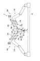
スレーブマニピュレータ20Aは、図2および図3示すように、基端部22Aが手術用天板(ベース)16に固定されたスレーブアーム(保持部)21Aと、スレーブアーム21Aの先端部23Aに固定された位置決めアーム(位置決め部)24Aと、位置決めアーム24Aに設けられた姿勢センサ(基準姿勢検出部)27A、着脱部駆動部28A、および変位検出部29Aと、後述する着脱部52Aに取り付けられた術具200の鉗子部203の初期状態における位置および姿勢を記憶する処置部初期位置検出部30Aと、鉗子部203の位置および姿勢を算出して記憶する処置部位置検出部31Aを有している。
なお、以下では、スレーブマニピュレータ20Aの構成については、数字の後に英字「A」を付加して示すことにする。2 and 3, the
In the following, the configuration of the
スレーブアーム21Aは、図2に示すように、台座32A、および2つの軸体33A、34Aが公知のボールジョイント35A、36Aにより接続された構成となっている。具体的には、台座32Aと軸体33Aとがボールジョイント35Aにより接続されていて、軸体33Aと軸体34Aとがボールジョイント36Aにより接続されている。台座32Aは手術用天板16に固定されている。なお、台座32Aがスレーブアーム21Aの基端部22Aを構成し、軸体34Aの先端部がスレーブアーム21Aの先端部23Aを構成する。
ボールジョイント35Aにより、台座32Aに対して軸体33Aを揺動させることができる。ボールジョイント36Aにより、軸体33Aに対して軸体34Aを揺動させることができる。
ボールジョイント35Aには、固定機構37Aが設けられていて、固定機構37Aによりボールジョイント35Aを構成する受け部に対してボールを固定させることができる。これにより、台座32Aに対して軸体33Aを固定させることができる。
同様に、ボールジョイント36Aには、固定機構38Aが設けられていて、軸体33Aに対して軸体34Aを固定させることができる。As shown in FIG. 2, the
The
The ball joint 35A is provided with a
Similarly, the ball joint 36A is provided with a
このように構成されたスレーブアーム21Aは、固定機構37A、38Aによる固定を解除したときには、台座32Aに対する軸体33A、34Aの位置を調節可能な調節モードとなる。一方で、固定機構37A、38Aにより固定したときには、台座32Aに対する軸体33A、34Aの位置を固定した固定モードとなる。
スレーブアーム21Aは、調節モードと固定モードとの間で切り替え可能となっている。The
The
位置決めアーム24Aは、いわゆる平行リンク41Aを備えている。具体的には、平行リンク41Aは、図3に示すように、互いに平行に配置された第一の辺要素42A、43A、44A、および、互いに平行に配置された第二の辺要素45A、46A、47Aを有している。第一の辺要素42A、43A、44A、および、第二の辺要素45A、46A、47Aは、ステンレス鋼などの金属などで棒状に形成されている。この例では、第一の辺要素43A、44Aの長さは互いに等しく設定され、第一の辺要素42Aは第一の辺要素43Aより短く設定されている。第一の辺要素43Aは、第一の辺要素42Aと第一の辺要素44Aとの間に並べて配置されている。
第二の辺要素45A、46Aの長さは互いに等しく設定され、第二の辺要素47Aは第二の辺要素45Aより短く設定されている。第二の辺要素46Aは、第二の辺要素45Aと第二の辺要素47Aとの間に並べて配置されている。The
The lengths of the
第一の辺要素44Aに設けられたピン48Aにより、第一の辺要素44Aに対して第二の辺要素45A、46A、47Aが基準平面S上で回動可能に支持されている。
同様に、第一の辺要素43Aに設けられたピン48Aにより、第一の辺要素43Aに対して第二の辺要素45A、46A、47Aが基準平面S上で回動可能に支持されている。第一の辺要素42Aに設けられたピン48Aにより、第一の辺要素42Aに対して第二の辺要素45A、46Aが基準平面S上で回動可能に支持されている。The
Similarly, the
第一の辺要素42Aの先端側を支持し、第一の辺要素42Aを基準平面Sと直交する平面上で回動可能にする回動機構55Aが設けられている。回動機構55Aを固定する固定部51Aが設けられている。固定部51Aによって、位置決めアーム24Aはスレーブアーム21Aに対して位置決め固定される。具体的には、固定部51Aは、スレーブアーム21Aの先端部23A、すなわち、軸体34Aの先端部に固定される。スレーブアーム21Aの軸体34Aと固定部51Aとは、ネジ止めや溶接などで固定されている。
これらの構成により、位置決めアーム24Aを固定部51Aに対して互いに直交する方向D1(基準平面S上)、方向D2(基準平面Sと直交する平面上)に揺動させたりすることができる。
第二の辺要素47Aには、術具200の術具挿入部201の基端部が着脱可能とされた着脱部52Aが、着脱部移動機構(処置部駆動部)53Aを介して取り付けられている。なお、この着脱部移動機構53Aと前述の着脱部駆動部28Aとで、駆動部を構成する。
着脱部52Aには、図4に示すように、着脱部52Aに術具200を取り付けたときに、術具200のワイヤ操作モータの電気接点と電気的に接続可能な着脱部側電気接点54Aが外部に露出した状態で備えられている。
着脱部側電気接点54Aは、制御装置60に接続されている。A
With these configurations, the
The
As shown in FIG. 4, the
The attachment / detachment portion side electrical contact 54 </ b> A is connected to the
着脱部移動機構53Aは、図3に示すように、着脱部52Aを移動させる公知の構成を有している。この例では、着脱部52Aに術具200を取り付けたときに、術具200の術具挿入部201は第二の辺要素47Aと平行になるように構成されている。
着脱部移動機構53Aは、着脱部52Aを、基準軸線C1上に設定される配置中心位置を中心として移動させることができる。具体的には、着脱部52Aに取り付けた術具200を着脱部52Aに対して、配置中心位置から基準軸線C1方向に進退させたり、基準軸線C1周りに回動させることができる。As shown in FIG. 3, the attaching / detaching
The attaching / detaching
本実施形態では姿勢センサ27Aは、図示はしないが、公知のジャイロスコープ、および、ジャイロスコープによる検出結果を処理してジャイロスコープの姿勢(向き)を検出する基準姿勢演算基板を有している。ジャイロスコープの姿勢は、例えば、図2に示す手術用天板16の上面に原点O0が規定される直交座標系であるグローバル座標系W0のそれぞれの軸回りの回転角度として表される。
姿勢センサ27Aは、図3に示すように位置決めアーム24Aの第二の辺要素45Aの長軸方向に取り付けられている。すなわち、この例では姿勢センサ27Aが姿勢を検出する基準位置V1は、第二の辺要素45A上、言い換えれば、位置決めアーム24Aの基端部に設定されている。姿勢センサ27Aは、基準位置V1における第二の辺要素45Aの長軸方向の姿勢を検出することができる。
このとき、術具200は第二の辺要素45Aと平行になるように構成されていることから、第二の辺要素45Aの基準位置V1における第二の辺要素45Aの長軸方向の姿勢は術具200の挿入方向の姿勢と略一致する。
姿勢センサ27Aにより検出された基準位置V1の姿勢は、図4に示すように制御装置60に送信される。In the present embodiment, the
The
At this time, since the
The attitude of the reference position V1 detected by the
着脱部駆動部28Aは、不図示のモータおよびギアを有している。モータを駆動してギアを回転させることで、図3に示す第一の辺要素43Aと第二の辺要素45Aとのなす角度θを、鋭角から鈍角まで調節することができる。
位置決めアーム24Aは前述のように構成されているため、角度θが定まれば位置決めアーム24Aの形状も一意に定まる。図3では角度θが約90°の状態を示しているが、着脱部駆動部28Aを駆動して図5に示すように角度θを鋭角にすると、固定部51Aに対する着脱部52Aの位置および姿勢を移動させることができる。The attaching / detaching
Since the
着脱位置検出部29Aは、図示はしないが、前述の角度θを検出するエンコーダなどの角度検出センサと、検出した角度θから基準位置V1に対する着脱部52Aの位置(距離)および姿勢(角度)を検出する着脱位置演算基板とを有している。着脱位置演算基板には、図示はしないが演算素子、メモリ、およびタイマが備えられている。
メモリには、隣り合うピン48A間の距離や、第二の辺要素45Aにおける基準位置V1が設定された位置や、第二の辺要素47Aにおける着脱部52Aが取り付けられた位置などが記憶されている。
演算素子は、メモリに記憶された各距離情報、および角度検出センサで検出された角度θから基準位置V1から着脱部52Aまでの距離(位置)および角度(姿勢)を算出することができる。Although not shown, the attachment / detachment
The memory stores the distance between
The arithmetic element can calculate the distance (position) and angle (posture) from the reference position V1 to the
また、演算素子は、タイマに設定された単位時間ごとに基準位置V1から着脱部52Aまでの距離および角度を検出し、検出した距離および角度情報は着脱部52Aの位置および姿勢としてメモリに記憶される。単位時間は、制御装置60の処理速度や手技の内容などに応じて、例えば、1ms(ミリ秒)から500ms程度に設定される。
演算素子は、メモリに記憶された単位時間おきの着脱部52Aの位置および姿勢から、基準位置V1に対する着脱部52Aの単位時間当たりの位置の変化量および姿勢の変化量を算出する。
着脱位置検出部29Aにより算出された前述の基準位置V1に対する着脱部52Aの位置および姿勢、着脱部52Aの位置の変化量および姿勢の変化量は、制御装置60に送信される(図4参照。)。The arithmetic element detects the distance and angle from the reference position V1 to the
The arithmetic element calculates the amount of change in position and the amount of change in posture of the attachment /
The position and orientation of the attachment /
処置部位置検出部31Aは、術具200の長さLなどを予め記憶するとともに、着脱部52Aに対する鉗子部203の位置および姿勢を算出する。この例では、術具挿入部201の基端部の位置に対して、鉗子部203の位置は、術具挿入部201の長手方向に長さL移動した位置となっている。
なお、この処置部位置検出部31Aと前述の着脱位置検出部29Aとで、変位検出部を構成する。The treatment unit
The treatment section
処置部位置検出部31Aは、基準位置V1の初期位置および姿勢センサ27Aが検出した姿勢から、着脱位置検出部29Aが検出した着脱部52Aの移動距離および角度だけ移動させ、さらに、着脱部52Aに対する鉗子部203の位置および姿勢だけ移動させた位置および姿勢を、鉗子部203における位置および姿勢として算出する。
具体的には、演算素子は、基準位置V1の初期位置に原点が規制されて第二の辺要素45Aの長軸方向を向く直交座標系であるローカル座標系WSを構成するある1つの軸(例えば、ZS軸。)に対して、着脱位置検出部29Aが検出した基準位置V1(原点)から着脱部52Aまでの距離を、着脱部52Aのその軸における位置として算出する。さらに、その軸において、着脱部52Aの位置から、着脱部52Aに対する鉗子部203の位置だけ移動させた位置として算出する。
この位置の算出は、ローカル座標系WSを構成する残りの2つの軸に対しても同様に行われる。The treatment unit
Specifically, the arithmetic device is one axis constituting the local coordinate system WS origin to the initial position of the reference position V1 is an orthogonal coordinate system oriented in the long axis direction of the
The calculation of the position is performed in the same manner for the remaining two axes constituting the local coordinate system WS.
一方で、鉗子部203の姿勢の算出については、グローバル座標系W0を構成するある1つの軸に対して、基準位置V1におけるその軸周りの回転角度に、着脱位置検出部29Aが検出した着脱部52Aのその軸周りの回転角度を足し合わせていくことで、着脱部52Aのその軸周りの回転角度(姿勢)を算出する。さらに、着脱部52Aの姿勢から、着脱部52Aに対する鉗子部203の姿勢だけ移動させた姿勢を、鉗子部203における姿勢として算出する。
この足し合わせによる回転角度、すなわち姿勢の算出は、グローバル座標系W0を構成する残りの2つの軸に対しても同様に行われる。Meanwhile, the calculation of the orientation of the
Rotation angle by the summing, i.e. calculate the orientation is performed in the same manner for the remaining two axes constituting the global coordinate system W0.
処置部初期位置検出部30Aは、初期状態において、処置部位置検出部31Aが算出した鉗子部203の位置および姿勢を記憶する。The treatment unit initial
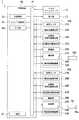
制御装置60は、図4に示すように、バス61に接続された主制御部62、スレーブ制御部(駆動部制御部)63、入力部64、および、電源67を有している。
バス61には、公知の内視鏡56、そして前述のマスタマニピュレータ10、表示部13、姿勢センサ27A、着脱位置検出部29A、処置部初期位置検出部30A、処置部位置検出部31A、着脱部駆動部28A、着脱部52A、および、着脱部移動機構53Aが金属製の配線により接続されている。
主制御部62、スレーブ制御部63は、それぞれがCPU(中央処理装置)、制御プログラムなどで構成される。As shown in FIG. 4, the
The
Each of the
スレーブ制御部63は、前述の操作指令に基づいて着脱部駆動部28Aおよび着脱部移動機構53Aを制御する。この制御方法については、後述する。The
主制御部62は、内視鏡56においてCCD(Charge Coupled Device)などを有する観察部で取得した画像を信号に変換したものを処理して表示部13に送信するなど、制御装置60に関する全般的な処理をする。
入力部64は、例えばキーボードであり、介助者が必要な指示を入力する。入力された指示は主制御部62などに送信される。
電源67は、マスタマニピュレータ10、内視鏡56、表示部13、スレーブマニピュレータ20A、および制御装置60の各構成に電力を供給する。The
The
The
次に、以上のように構成された本実施形態の手術支援装置1を用いた手技を、スレーブマニピュレータ20A、および制御装置60の動作に重点をおいて説明する。以下では、患者の体腔内に術具200を導入して対象組織を処置する場合を例にとって説明する。Next, a procedure using the surgery support apparatus 1 of the present embodiment configured as described above will be described with emphasis on the operations of the
手術支援装置1を起動すると、制御装置60の電源67からマスタマニピュレータ10、スレーブマニピュレータ20Aなどに電力が供給される。この時点では、スレーブアーム21Aは固定モードになっている。
介助者は、手術用天板16に図1および2に示すように患者Pを寝かせて必要な処置をする。不図示のナイフなどで、図3に示すように患者Pの体壁P1を切開して開口P2を形成する。この開口P2には、図示はしないがトロッカーを取り付けておく。
使用者Qの指示に基づいて、着脱部52Aに術具200の術具挿入部201の基端部を取り付ける。体壁P1に形成した別の開口から内視鏡56を導入し、観察部で取得した画像を表示部13で確認しながら処置を行う。
スレーブアーム21Aを調節モードに切り替えてスレーブアーム21Aを変形させ、術具200の鉗子部203を開口P2を通して患者Pの体腔P3内に導入する。このとき、術具200は下方に延びており、位置決めアーム24Aの角度θは、約90°になっているとする。When the surgery support device 1 is activated, power is supplied from the
The caregiver lays the patient P on the surgical top 16 as shown in FIGS. 1 and 2 and performs necessary treatment. An opening P2 is formed by incising the body wall P1 of the patient P with a knife (not shown) as shown in FIG. Although not shown, a trocar is attached to the opening P2.
Based on the instruction of the user Q, the proximal end portion of the surgical
The
このように術具200を位置決めした後で、スレーブアーム21Aを固定モードに切り替える。
入力部64を操作して、姿勢センサ27A、着脱位置検出部29A、および処置部位置検出部31Aで検出した回転角度を足し合わせた鉗子部203における回転角度を鉗子部203の初期姿勢として処置部初期位置検出部30Aに記憶させる(イニシャライズする。)。また、基準位置V1における初期位置を仮想原点としたときの鉗子部203の位置を鉗子部203の初期位置として処置部初期位置検出部30Aに記憶させる。
処置部初期位置検出部30Aは、記憶した鉗子部203の初期位置および初期姿勢をスレーブ制御部63に送信する。After positioning the
By operating the
The treatment unit initial
続いて、使用者Qは椅子12に座り、右手Q1および左手Q2で一対のマスタマニピュレータ10をそれぞれ把持し操作する。ここでは、使用者Qがマスタマニピュレータ10を操作して着脱部駆動部28Aを駆動させることで術具200を揺動させて、鉗子部203の水平方向の位置を変化させる場合で説明する。
以下では、説明の便宜のため鉗子部203の位置のみに着目して説明する。Subsequently, the user Q sits on the
Hereinafter, for convenience of explanation, only the position of the
図6において、曲線L1は操作指令による鉗子部203の水平方向の位置(目標値)であり、曲線L2は制御装置60が認識している鉗子部203の位置(測定値)である。
操作開始時刻T0から、使用者Qはマスタマニピュレータ10を操作して、術具200の鉗子部203を図3中の矢印Bのように移動させる操作指令を曲線L1に示すように発したとする。In FIG. 6, a curved line L1 is a horizontal position (target value) of the
From the operation start time T0 , the user Q operates the
まず、目標変化量算出工程において、スレーブ制御部63は、操作開始時刻T0から単位時間△T経過した時刻T1に、操作指令に表される鉗子部203における操作開始時刻T0から時刻T1までの単位時間△T当たりの目標位置の変化量△Z1を算出する。
次に、移動工程において、スレーブ制御部63は、鉗子部203が単位時間△T当たりに目標位置の変化量△Z1だけ移動するように、すなわちイニシャライズ時に記憶した鉗子部203の初期位置からの変化量が△Z1となるように着脱部駆動部28Aを制御する。具体的には、時刻T1に前述の角度θが小さくなるように(図5参照。)制御する。First, the target change amount calculation step, the
Then, in the moving step, the
続いて、目標変化量算出工程において、スレーブ制御部63は、時刻T1から単位時間△T経過した時刻T2に、操作指令に表される鉗子部203における操作開始時刻T1から時刻T2までの単位時間△T当たりの目標位置の変化量△Z2を算出する。
次に、移動工程において、スレーブ制御部63は、鉗子部203が単位時間△T当たりに目標位置の変化量△Z2だけ移動するように、すなわち時刻T1での鉗子部203の位置からの変化量が△Z2となるように着脱部駆動部28Aを制御する。具体的には、時刻T2に角度θが小さくなるように制御する。Subsequently, the target change amount calculation step, the
Then, in the moving step, the
このように、目標変化量算出工程と移動工程とを組にして所望の回数だけ繰り返し、変化量△Z3、△Z4、・・と順々に鉗子部203を図3中に矢印Bのように揺動させる。組にして繰り返す数は、1回だけでもよいし2回以上でもよい。
なお、術具200は、前述のように平行リンク41Aに取り付けられているため、第一の辺要素42Aと、着脱部52Aに取り付けられた術具200との交点を不動点(ポート位置)としたときに、平行リンク41Aの角度θによらず、術具200は不動点上に配置される。すなわち、患者Pの開口P2が不動点に一致するようにスレーブマニピュレータ20Aを移動させることで、平行リンク41Aの角度θによらず術具200が開口P2を通る。In this way, the target change amount calculation step and the movement step are repeated as many times as desired, and the change amount ΔZ3 , ΔZ4 ,. Oscillate as follows. The number of repetitions in a set may be only once or two or more times.
Since the
また、このようにマスタマニピュレータ10を操作して術具200を揺動させる途中で、例えば、電源67の故障などにより手術支援装置1の動作が緊急的に停止してしまうことが考えられる。
例えば、図6に示すように、鉗子部203を変化量△Z2移動させる直前に手術支援装置1の動作が緊急的に停止したとする。この場合、鉗子部203の移動は変化量で制御されているため、電源67が治って手術支援装置1の動作が開始されたときに、曲線L3で示されるように変化量△Z2だけ移動しようとする。
一方で、本発明とは異なり、鉗子部203を目標位置で制御した場合には、手術支援装置の動作が開始されたときに、曲線L4で示されるように、手術支援装置の動作が開始したときの目標位置に移動させようとして、鉗子部が、例えば(△Z2+△Z3+△Z4)の式で求められる値だけ、大きく移動する恐れがある。
ここでは鉗子部203の位置のみに着目して説明したが、鉗子部203の姿勢に関しても同様である。Further, during the operation of the
For example, as shown in FIG. 6, the operation of the operation support apparatus 1 immediately before moving the change amount △ Z2 forceps portion 203 and stopped in emergency. In this case, the movement because it is controlled by the movement change amount of the
On the other hand, unlike the present invention, when the
Here, the description has been made focusing only on the position of the
再び、手術支援装置1を用いた手技の説明を行う。
使用者Qは、マスタマニピュレータ10を操作して着脱部駆動部28Aにより術具200を揺動させ、図3に示すように鉗子部203を体腔P3内の処置対象となる病変部P6に対向させる。着脱部移動機構53Aにより術具200が取り付けられた着脱部52Aを押し込んで病変部P6に鉗子部203を当接させる。必要に応じて、着脱部移動機構53Aにより、術具200を基準軸線C1周りに回動させる。
着脱部52Aを介して術具200のワイヤ操作モータに電力を供給して一対の鉗子片202を閉じさせ、病変部P6を把持させる。
この後で、病変部P6に対して適切な処置を行い、一連の手技を終了する。The procedure using the surgery support apparatus 1 will be described again.
The user Q operates the
Electric power is supplied to the wire operation motor of the
Thereafter, appropriate treatment is performed on the lesioned part P6, and a series of procedures is completed.
以上説明したように、本実施形態のスレーブマニピュレータ20Aによれば、位置決めアーム24Aにはグローバル座標系W0における姿勢を検出可能な姿勢センサ27Aが設けられている。このため、従来のようにスレーブアーム21Aの各関節に角度検出センサなどを設けることなく、位置決めアーム24Aの基準位置V1の位置および姿勢を検出することができる。さらに、変位検出部により、基準位置V1に対する鉗子部203の姿勢を検出することができる。
このように、姿勢センサ27A、変位検出部という2つのセンサを備えることで、グローバル座標系W0における着脱部52Aの姿勢を検出することができる。したがって、鉗子部203の姿勢を検出するために必要なセンサの数を低減させることができる。As described above, according to the
Thus, by providing
位置決めアーム24Aが平行リンク41Aを備えることで、患者Pの開口P2が不動点に一致するようにスレーブマニピュレータ20Aを移動させた状態でスレーブアーム21Aを固定モードにすることで、平行リンク41Aの角度θによらず術具200が開口P2を通る。
このため、術具200の揺動角度によらず、術具200が開口P2の縁部に外力を及ぼすことを抑制することができる。Since the
For this reason, it can suppress that the
基準位置V1が、スレーブアーム21Aの第二の辺要素45A上、すなわち、位置決めアーム24Aの基端部に設定されているため、スレーブアーム21Aを固定モードにした後で基準位置V1が移動しない。着脱位置検出部29Aで検出する着脱部52Aの位置および姿勢の起点となる基準位置V1が移動しないため、着脱部52Aの位置および姿勢を容易に算出することができる。
処置部位置検出部31Aは、予め記憶した術具200の長さLなどの情報、および、算出した着脱部52Aの位置および姿勢から、鉗子部203の位置および姿勢を算出する。したがって、着脱部52Aの位置および姿勢だけでなく、実際に処置を行う部位である鉗子部203の位置および姿勢を算出し、精度よく制御を行うことができる。Since the reference position V1 is set on the
The treatment unit
また、本実施形態の手術支援装置1によれば、スレーブ制御部63が操作指令に表される着脱部52Aの単位時間△T当たりの目標位置の変化量および目標姿勢の変化量にしたがって着脱部駆動部28Aを制御する。このため、手術支援装置1の動作が緊急的に停止した場合であっても、動作が開始した手術支援装置1の着脱部52Aや鉗子部203が大きく移動するのを抑制することができる。
さらに、単位時間△T当たりの目標位置の変化量にしたがって着脱部駆動部28Aを制御することで、グローバル座標系W0における着脱部52Aの絶対値位置座標が不明であっても、イニシャライズにより設定された基準位置V1あるいは着脱部52Aの初期位置に対して、術具200の位置を相対的に制御することができる。Moreover, according to the surgery support apparatus 1 of the present embodiment, the detachable unit according to the amount of change in the target position and the amount of change in the target posture per unit time ΔT of the
Further setting, by controlling the
なお、本実施形態では、イニシャライズ時に着脱部52Aの位置および姿勢を初期位置および初期姿勢として記憶したが、基準位置V1の位置および姿勢を初期位置および初期姿勢として記憶してもよい。この場合も、本実施形態と同様の効果を奏することができるからである。
本実施形態では、位置決めアーム24Aに術具200を着脱可能に支持する着脱部52Aを設けたが、位置決めアーム24Aと術具200を一体として固定支持するように構成してもよい。この場合も、イニシャライズ時に基準位置V1の位置および姿勢を初期位置および初期姿勢として記憶しておけば、基準位置V1に対して、術具200の位置を相対的に制御することができる。
本実施形態では、位置決めアーム24Aに着脱部52Aを移動させる着脱部駆動部28Aを設けたが、位置決めアーム24Aに着脱部駆動部28Aを設けず、術具200のみを移動させる着脱部移動機構53Aを設けるような構成にしてもよい。この場合も、イニシャライズ時に基準位置V1あるいは着脱部52Aの位置および姿勢を初期位置および初期姿勢として記憶しておけば、初期位置に対して、術具200の位置を相対的に制御することができる。In the present embodiment, the position and orientation of the
In the present embodiment, the attachment /
In this embodiment, the attachment / detachment
本実施形態では、手術支援装置1に複数のスレーブマニピュレータ20Aを備えるとともに、1つの姿勢センサ27Aが、それぞれのスレーブマニピュレータ20Aの第二の辺要素45A上に着脱可能に取り付けられるように構成してもよい。第二の辺要素45Aと姿勢センサ27Aとの着脱は、係合部と被係合部とによる機械的な方式や、磁石などの磁気的な方式を用いることができる。
1つのスレーブマニピュレータ20Aについて、スレーブアーム21Aを固定モードにした後で、一度、姿勢センサ27Aにより基準位置V1の位置および姿勢を検出すれば、そのスレーブマニピュレータ20Aについてはスレーブアーム21Aを固定モードにしている間は姿勢センサ27Aは不要となる。
姿勢センサ27Aをこのように構成することで、手術支援装置1全体としての製造コストを低減させることができる。In the present embodiment, the surgery support apparatus 1 includes a plurality of
After the
By configuring the
本実施形態では、姿勢センサ27Aは位置決めアーム24Aの第二の辺要素45Aに取り付けられているとしたが、姿勢センサ27Aが取り付けられる位置は、位置決めアーム24Aの基準位置V1の位置および姿勢が検出可能であれば特に限定されない。例えば、図7に示す手術支援装置1のように、姿勢センサ27Aを着脱部移動機構53Aに取り付けてもよい。この場合であっても、姿勢センサ27Aを着脱部移動機構53Aに取り付ける位置の情報が予め姿勢センサ27Aに記憶されていれば、位置決めアーム24Aにおける基準位置の位置および姿勢を検出可能であるからである。
また、姿勢センサ27Aはスレーブアーム21Aに取り付けてもよい。スレーブアーム21Aと位置決めアーム24Aとの位置・姿勢関係が予め姿勢センサ27Aに記憶されていれば、位置決めアーム24Aにおける基準位置の位置および姿勢を検出可能であるからである。In this embodiment, the
Further, the
着脱位置検出部29Aは、第一の辺要素42A、43A、44Aのいずれかと、第二の辺要素45A、46A、47Aのいずれかとがなす角度θが検出可能であれば、取り付け位置は特に限定されない。
また、本実施形態では、姿勢センサ27Aにおける基準姿勢演算基板、および、着脱位置検出部29Aにおける着脱位置演算基板を制御装置60内に配置してもよい。このように構成することで、制御基板を一体化して、制御基板を全体としてコンパクトに構成することができる。
平行リンク41Aが第一の辺要素43Aおよび第二の辺要素46Aを備えずに、平行リンク41Aが一対の第一の辺要素42A、44A、および、一対の第二の辺要素45A、47Aだけを有するように構成してもよい。The attachment / detachment
In the present embodiment, the reference posture calculation board in the
The
本実施形態では、スレーブアーム21Aの先端部23Aに、位置決めアーム24Aの固定部51Aが固定されているとしたが、スレーブアーム21Aの先端部23Aに固定部51Aが着脱可能となるように構成してもよい。
ここで、スレーブアーム21Aを患者Pの開口P2に対応させて適切な形状に変形させるスレーブアーム変形工程、位置決めアーム24Aを自身の不動点が患者Pの開口P2に一致するように配置する位置決めアーム配置工程、および、スレーブアーム21Aの先端部23Aに位置決めアーム24Aの固定部51Aを取り付ける取り付け工程を規定する。これら、スレーブアーム変形工程、位置決めアーム配置工程、および取り付け工程の順序は特に制限はなく、任意の順序で行うことができる。これら3つの工程を行った後で、前述の目標変化量算出工程と移動工程とを組にして繰り返すことになる。In the present embodiment, the fixed
Here, a slave arm deforming step for deforming the
姿勢センサ27Aと処置部初期位置検出部30Aとが配線により接続されているとした。しかし、姿勢センサ27Aが、検出した基準位置V1の姿勢を無線通信により処置部初期位置検出部30Aに送信するように構成してもよい。
このように構成することで、スレーブマニピュレータ20Aを小型化することができる。It is assumed that the
With this configuration, the
本実施形態では、スレーブ制御部63は、目標変化量算出工程において、処置部203の単位時間△T当たりの目標位置の変化量および目標姿勢の変化量を算出し、移動工程において目標位置の変化量および目標姿勢の変化量に基づいて制御するとした。しかし、スレーブ制御部63は、目標変化量算出工程において、標位置の変化量および目標姿勢の変化量の一方のみを算出し、移動工程においてこの一方のみに基づいて制御するとしてもよい。In the present embodiment, the
(第2実施形態)
次に、本発明の第2実施形態について図8および図9を参照しながら説明するが、前記実施形態と同一の部位には同一の符号を付してその説明は省略し、異なる点についてのみ説明する。
図8に示すように、本実施形態の手術支援装置2は、第1実施形態の手術支援装置1の各構成に加えて、前述の内視鏡56が着脱可能な着脱部52Bを有する本発明のスレーブマニピュレータ20Bを備えている。
なお、スレーブマニピュレータ20Bの構成はスレーブマニピュレータ20Aと同一であるため、スレーブマニピュレータ20Bの構成については、スレーブマニピュレータ20Aにおける対応する構成の符号の数字に英字「B」を付加することで示す。これにより、重複する説明を省略する。(Second Embodiment)
Next, a second embodiment of the present invention will be described with reference to FIG. 8 and FIG. 9. However, the same parts as those of the above embodiment are denoted by the same reference numerals, and the description thereof will be omitted. explain.
As shown in FIG. 8, the
Since the configuration of the
位置決めアーム24Bに取り付けられた着脱部52Bには、光軸C2に沿った外方の画像を取得するための観察部56aが設けられた内視鏡56が着脱可能となっている。
着脱部52Bに内視鏡56を取り付けたときに、観察部56aで取得された画像は、主制御部62で処理されて表示部13に表示されるようになっている(図9参照。)。An
When the
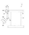
ここで、図8に示すように術具200の処置部203に原点O1が規定されて処置部203の先端側を向く直交座標系である第一のローカル座標系(第一の直交座標系)W1を規定する。すなわち、この第一のローカル座標系W1のZ1軸は、処置部203を起点として処置部203の先端側を向いている。同様に、内視鏡56の観察部56aに原点O2が規定されて光軸C2に沿って先端側を向く直交座標系である第二のローカル座標系(第二の直交座標系)W2を規定する。すなわち、この第二のローカル座標系W2のZ2軸は、観察部56aを起点として光軸C2に沿って先端側を向いている。
第一のローカル座標系W1から第二のローカル座標系W2への変換は、公知のように変換行列Aで表される。
スレーブ制御部63は、マスタマニピュレータ10が発するグローバル座標系W0における目標位置および目標姿勢を表す操作指令を、変換行列Aで変換して変換操作指令を算出し、この変換操作指令に基づいて着脱部駆動部28Aを制御する。Here, as shown in FIG. 8, a first local coordinate system (first orthogonal coordinate system) which is an orthogonal coordinate system in which the origin O1 is defined in the
The conversion of one of the local coordinate system W1 to the second local coordinate system W2 is represented by the transformation matrix A as known.
The
このように構成された本実施形態の手術支援装置2によれば、鉗子部203の位置および姿勢を検出するために必要なセンサの数を低減させることができる。
さらに、内視鏡56の光軸C2の先端側の姿勢と、処置部203の先端側の姿勢とが一致するように座標変換することで、表示部13に表示される画像上に映し出される処置部203の先端(処置部203)の姿勢とマスタマニピュレータ10の姿勢とを対応させやすくなる。したがって、表示部13に表示される画像を見ながらのマスタマニピュレータ10の操作性を向上させることができる。According to the
Further, the treatment displayed on the image displayed on the
なお、本実施形態では、手術支援装置2がスレーブマニピュレータ20Bを備え、スレーブマニピュレータ20Bの着脱部52Bに内視鏡56が着脱可能であるとした。しかし、スレーブマニピュレータ20Bは手術支援装置2に必須の構成ではなく、手術支援装置2が内視鏡56および表示部13を備えていればよい。内視鏡56が何に取り付けられていても、本実施形態と同様の効果を奏することができるからである。
ただし、手術支援装置2がスレーブマニピュレータ20Bを備え、スレーブマニピュレータ20Bに内視鏡56が着脱可能とすることで、内視鏡56の観察部56aの操作性を向上させることができる。In the present embodiment, the
However, the
(第3実施形態)
次に、本発明の第3実施形態について図10および図11を参照しながら説明するが、前記実施形態と同一の部位には同一の符号を付してその説明は省略し、異なる点についてのみ説明する。
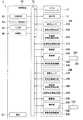
図10および11に示すように、本実施形態の手術支援装置3は、第1実施形態の手術支援装置1の各構成に加えて、術具(第二の術具)210が着脱可能な着脱部52Bを有する本発明のスレーブマニピュレータ(第二の医療用マニピュレータ)20Bを備えている。
すなわち、手術支援装置3は、スレーブマニピュレータ(第一の医療用マニピュレータ)20Aおよびスレーブマニピュレータ20Bの2つのスレーブマニピュレータを備えている。
前述の術具(第一の術具)200の術具挿入部201の先端部には接触センサ(送信部)205が設けられている。
制御装置60には記憶部65が備えられている(図11参照。)。(Third embodiment)
Next, a third embodiment of the present invention will be described with reference to FIG. 10 and FIG. explain.
As shown in FIGS. 10 and 11, the
That is, the
A contact sensor (transmission unit) 205 is provided at the distal end portion of the surgical
The
第二の術具210の構成は硬性であれば特に限定されないが、本実施形態では前述の術具200と同一の鉗子が用いられている。すなわち、第二の術具210は、術具挿入部211の先端部に一対の鉗子片212からなる鉗子部(処置部)213が設けられたものである。
術具200に設けられた接触センサ205は、鉗子部203に外力が加わったことを検出するセンサである。接触センサ205は、術具200の鉗子部203と術具210の鉗子部213とが接触したときに、着脱部52Aの着脱部側電気接点54Aを介してスレーブ制御部63および記憶部65に制御信号を送信する。The configuration of the second
A
スレーブ制御部63は制御信号を受信したときの、基準位置V1に対する鉗子部203の位置および姿勢、および基準位置V2に対する鉗子部213の位置および姿勢から、基準位置V1と基準位置V2との相対的な位置関係を算出する。
記憶部65はメモリなどで構成されていて、スレーブ制御部63で算出された基準位置V1と基準位置V2との相対的な位置関係、すなわちスレーブマニピュレータ20Aとスレーブマニピュレータ20Bの相対位置関係を記憶する。When the
The
次に、以上のように構成された本実施形態の手術支援装置3の動作について説明する。
手術支援装置3を起動し、スレーブマニピュレータ20Aの着脱部52Aに術具200を取り付けるとともに、スレーブマニピュレータ20Bの着脱部52Bに術具210を取り付ける。スレーブアーム21A、21Bを所望の形状に変形させた後で、スレーブアーム21A、21Bをそれぞれ固定モードにする。Next, operation | movement of the
The
使用者Qは、一対のマスタマニピュレータ10を操作してスレーブ制御部63により着脱部駆動部28A、28Bを駆動し、術具200の鉗子部203と術具210の鉗子部213とを接触させる。すると、接触センサ205は鉗子部203に外力が加わったことを検出し、記憶部65に制御信号を送信する。記憶部65は、鉗子部203と鉗子部213とが接触したときの鉗子部203、213の位置および姿勢を、鉗子部203の接触位置および接触姿勢、鉗子部213の接触位置および接触姿勢としてそれぞれ記憶する。The user Q operates the pair of
続いて、使用者Qは、スレーブ制御部63により着脱部駆動部28A、28Bを駆動するが、このとき、スレーブ制御部63は、算出した基準位置V1と基準位置V2との相対的な位置関係を基に、スレーブマニピュレータ20Aおよびスレーブマニピュレータ20Bの動作範囲を算出し、鉗子部203と鉗子部213、あるいはスレーブマニピュレータ20Aとスレーブマニピュレータ20Bが互いに干渉しないように制御する。
具体的には、使用者Qが鉗子部203、213あるいはスレーブマニピュレータ20A、20B同士が接触するような操作指令を発したときには、スレーブ制御部63は、例えば着脱部駆動部28A、28Bの動作を停止させるとともに、警告を意味する表示や音を発して使用者Qに注意を促すことが好ましい。Subsequently, the user Q drives the attachment / detachment
Specifically, when the user Q issues an operation command such that the
このように構成された本実施形態の手術支援装置3によれば、鉗子部203の位置および姿勢を検出するために必要なセンサの数を低減させることができる。
さらに、接触センサ205および記憶部65を備えて前述のようにスレーブ制御部63が制御することで、スレーブ制御部63は鉗子部203と鉗子部213とが接触するときのスレーブマニピュレータ20A、20Bの相対位置を認識することができ、各スレーブマニピュレータ20A、20Bの動作範囲がどのように干渉するかなどを確認することができる。
そして、スレーブマニピュレータ20A、20B同士が接触などの動作干渉が起きないように制御することができる。According to the
In addition, the
The
本実施形態では送信部として接触センサ205を用いたが、術具200の鉗子部203術具210の鉗子部213とが接触したときに、記憶部65に制御信号を送信可能なものであればよい。送信部は、以下に説明するような様々な構成とすることができる。
例えば、術具200の術具挿入部201の先端部に、送信部として微弱振動の発生源と、振動の振幅を検出する振幅検出センサとを備えてもよい。一定の振幅で振動している鉗子部203に鉗子部213が接触すると、鉗子部203の振幅が変化する。このため、鉗子部203に鉗子部213が接触しているか否かを検出することができる。In the present embodiment, the
For example, the distal end portion of the surgical
送信部として、超音波を発生させる超音波発生源と、鉗子部213で反射された超音波を検出する超音波受信部とを備えてもよい。
鉗子部203の周辺の画像をCCDなどの撮像素子で取得し、この画像を公知の画像処理技術により解析することで、鉗子部203に鉗子部213が接触しているか否かを検出してもよい。
また、送信部をスイッチなどで構成してもよい。この場合、鉗子部203の周辺を介助者などが内視鏡により観察し、鉗子部203と鉗子部213とが接触したときに介助者がスイッチを切り替えて記憶部65に制御信号を送信することになる。As a transmission part, you may provide the ultrasonic wave generation source which generates an ultrasonic wave, and the ultrasonic wave reception part which detects the ultrasonic wave reflected by the forceps part 213.
Even if it detects whether the forceps part 213 is contacting the
Further, the transmission unit may be configured by a switch or the like. In this case, an assistant or the like observes the periphery of the
以上、本発明の第1実施形態から第3実施形態について図面を参照して詳述したが、具体的な構成はこの実施形態に限られるものではなく、本発明の要旨を逸脱しない範囲の構成の変更なども含まれる。さらに、各実施形態で示した構成のそれぞれを適宜組み合わせて利用できることは、言うまでもない。
たとえば、前記第1実施形態から第3実施形態では、スレーブマニピュレータ20Aが手術用天板16に固定されているとしたが、図12に示す手術支援装置4のように構成してもよい。すなわち、手術支援装置4では、ロボット用天板71を結合具72により手術台15の手術用天板16に固定するとともに、このロボット用天板71の側面に設けられた一対のガイドレール73にスレーブマニピュレータ20A、20Bを固定している。
なお、図12以下では、説明の便宜のために前述の平行リンクを箱状に描いて示している。The first to third embodiments of the present invention have been described in detail with reference to the drawings. However, the specific configuration is not limited to this embodiment, and the configuration does not depart from the gist of the present invention. Changes are also included. Furthermore, it goes without saying that the configurations shown in the embodiments can be used in appropriate combinations.
For example, in the first to third embodiments, the
In FIG. 12 and subsequent figures, the above-described parallel links are illustrated in a box shape for convenience of explanation.
各ガイドレール73は、図12を表示する表示面に直交するように延びていて、スレーブマニピュレータ20A、20Bはガイドレール73の長手方向の任意の位置にスライドした状態で固定できるようになっている。すなわち、スレーブマニピュレータ20A、20Bの相対位置の情報を、スレーブマニピュレータ20A、20Bの拘束条件として制御装置60の記憶部などに設定できるようになっている。
なお、本変形例では、手術支援装置4に2基のスレーブマニピュレータ20A、20Bが備えられているとしたが、手術支援装置4に備えられるスレーブマニピュレータの数に制限はなく、1基でもよいし、3基以上でもよい。これは、前記第1実施形態から第3実施形態でも同様である。Each
In this modification, the surgery support device 4 is provided with two
図13および14に示す手術支援装置5のように、手術用天板16の側面に設けられた回転機構76を介してスレーブマニピュレータ20A、20Bを固定してもよい。
回転機構76は、公知の構成を有していて、手術用天板16の側面に設けられた一対の支持部材77と、支持部材77により自身の軸線C4周りに回動可能に支持されたベッドレール78とを有している。ベッドレール78は、支持部材77に設けられた不図示の固定機構により、支持部材77に対して軸線C4周りに回動可能な回動モードと、この回動を規制された規制モードとの間で切り替えることができる。
ベッドレール78の一方の端部にはハンドル79が取り付けられている。
スレーブマニピュレータ20Aの台座32A、およびスレーブマニピュレータ20Bの台座32Bは、ベッドレール78に固定されている。The slave manipulators 20 </ b> A and 20 </ b> B may be fixed via a
The
A
The
このように構成された本変形例の手術支援装置5を用いて、術具200をスレーブマニピュレータ20Aに取り付け、患者Pの体腔P3内に術具200を導入して処置を行う。このとき、スレーブアーム21Aは固定モードになり、固定機構は規制モードになっている。
処置を行う間に、場合によっては、緊急的に術具200を患者Pから引き抜く必要がある。
このような場合には、介助者は、体腔P3内から術具200を引き抜いた後で、スレーブマニピュレータ20Aから術具200を取り外し、固定機構を回動モードに切り替える。ハンドル79を把持して、図15に示すようにベッドレール78を軸線C4周りに回動させ、スレーブマニピュレータ20A、およびスレーブマニピュレータ20Bを手術用天板16上から手術用天板16の下方に退避させる。
このように構成された本変形例の手術支援装置5によれば、スレーブマニピュレータ20A、20Bを手術用天板16上から素早く退避させることができる。Using the surgical
In some cases, it is necessary to urgently withdraw the
In such a case, the assistant removes the
According to the surgical
前記第1実施形態から第3実施形態では、位置決めアームが平行リンクを備えるとした。しかし、開腹手術などの場合のように、術具を不動点を通す必要がない場合には、位置決めアームは平行リンクを備えなくてもよい。
また、着脱部の位置および姿勢から着脱部に取り付けられた術具の鉗子部の位置および姿勢が容易に推測できてマスタマニピュレータ10で操作できるような場合などには、処置部位置検出部は備えられなくてもよい。
着脱部52Aを第二の辺要素47Aに設定したが、着脱部52Aは第二の辺要素45A、46Aに設定してもよい。In the first to third embodiments, the positioning arm includes the parallel link. However, when it is not necessary to pass the surgical tool through the fixed point as in the case of open surgery, the positioning arm may not include the parallel link.
In addition, in the case where the position and posture of the forceps portion of the surgical instrument attached to the detachable portion can be easily estimated from the position and posture of the detachable portion and can be operated by the
Although the
スレーブアームを、軸体をボールジョイントで接続することで構成したが、スレーブアームの構成はこれに限定されない。スレーブアームの自由度が3以上であれば、例えば、スレーブアームを複数のリニアガイドや関節部で構成してもよい。Although the slave arm is configured by connecting the shaft bodies with ball joints, the configuration of the slave arm is not limited to this. If the degree of freedom of the slave arm is 3 or more, for example, the slave arm may be composed of a plurality of linear guides or joints.
1、2、3、4、5 手術支援装置
10 マスタマニピュレータ(入力部)
13 表示部
16 手術用天板(ベース)
20A スレーブマニピュレータ(医療用マニピュレータ、第一の医療用マニピュレータ)
20B スレーブマニピュレータ(医療用マニピュレータ、第二の医療用マニピュレータ)
21A、21B スレーブアーム(保持部)
22A 基端部
23A 先端部
24A、24B 位置決めアーム(位置決め部)
27A、27B 姿勢センサ(基準姿勢検出部)
28A、28B 着脱部駆動部
29A、29B 着脱位置検出部
30A 処置部初期位置検出部
31A、31B 処置部位置検出部
51A 固定部
52A、52B 着脱部
53A 着脱部移動機構(処置部駆動部)
56 内視鏡
56a 観察部
63 スレーブ制御部(駆動部制御部)
65 記憶部
200 術具(第一の術具)
203、213 鉗子部(処置部)
205 接触センサ(送信部)
210 術具(第二の術具)
C2 光軸
S 基準平面
V1、V2 基準位置
W1 第一のローカル座標系(第一の直交座標系)
W2 第二のローカル座標系(第二の直交座標系)
θ 角度1, 2, 3, 4, 5
13
20A Slave manipulator (medical manipulator, first medical manipulator)
20B Slave manipulator (medical manipulator, second medical manipulator)
21A, 21B Slave arm (holding part)
22A Base end
27A, 27B Posture sensor (reference posture detection unit)
28A, 28B Attachment /
56
65
203, 213 Forceps part (treatment part)
205 Contact sensor (transmitter)
210 surgical tool (second surgical tool)
C2 Optical axis S Reference plane V1, V2 Reference position W1 First local coordinate system (first orthogonal coordinate system)
W2second local coordinate system (second orthogonal coordinate system)
θ angle
Claims (11)
Translated fromJapanese前記保持部の先端部に固定される固定部、および術具の処置部が前記固定部に対して移動可能に構成された位置決め部と、
前記位置決め部における基準位置の姿勢を検出する基準姿勢検出部と、
前記固定部に対して前記処置部を移動させるための駆動部と、
前記基準位置に対する前記処置部の角度変位を含む移動量を検出し、前記基準姿勢検出部が検出した前記基準位置の姿勢から、自身が検出した角度変位だけ移動させた姿勢を、前記処置部における姿勢として算出する変位検出部と、
を備えることを特徴とする医療用マニピュレータ。A holding portion whose base end is fixed to the base;
A fixing portion fixed to the distal end portion of the holding portion, and a positioning portion configured such that a treatment portion of a surgical instrument is movable with respect to the fixing portion;
A reference posture detection unit for detecting a posture of a reference position in the positioning unit;
A drive unit for moving the treatment unit relative to the fixed unit;
The amount of movement including the angular displacement of the treatment unit with respect to the reference position is detected, and the posture moved by the angular displacement detected by itself from the posture of the reference position detected by the reference posture detection unit in the treatment unit. A displacement detector that calculates the posture;
A medical manipulator comprising:
前記駆動部は、
前記固定部に対して前記着脱部を移動させる着脱部駆動部と、
前記着脱部に対して前記処置部を移動させる処置部駆動部とから構成され、
前記変位検出部は、
前記固定部に対する前記着脱部の角度変位を含む移動量を検出する着脱位置検出部と、
前記着脱部に対する前記処置部の角度変位を含む移動量を検出する処置部位置検出部とを備えることを特徴とする請求項1に記載の医療用マニピュレータ。The positioning part has an attaching / detaching part to which the surgical instrument is attachable / detachable,
The drive unit is
An attaching / detaching unit driving unit for moving the attaching / detaching unit with respect to the fixing unit;
A treatment unit driving unit that moves the treatment unit relative to the attachment / detachment unit;
The displacement detector is
An attachment / detachment position detection unit for detecting a movement amount including an angular displacement of the attachment / detachment unit with respect to the fixing unit;
The medical manipulator according to claim 1, further comprising a treatment portion position detection portion that detects a movement amount including an angular displacement of the treatment portion with respect to the attachment / detachment portion.
前記基端部に対する前記先端部の位置を調節可能な調節モードと、
前記基端部に対する前記先端部の位置を固定した固定モードとの間で切り替え可能である請求項1又は2に記載の医療用マニピュレータ。The holding part is
An adjustment mode capable of adjusting the position of the tip with respect to the base end;
The medical manipulator according to claim 1, wherein the medical manipulator can be switched between a fixed mode in which a position of the distal end portion with respect to the proximal end portion is fixed.
使用者からの入力に基づいて操作指令を発する入力部と、
前記操作指令に基づいて前記駆動部を制御する駆動部制御部と、
を備える手術支援装置であって、
前記変位検出部は、前記基準位置に対する前記処置部の単位時間当たりの位置の変化量を検出し、
前記駆動部制御部は、
前記操作指令に表される前記処置部の前記単位時間当たりの目標位置の変化量を算出する目標変化量算出工程と、
前記処置部が前記単位時間当たりに前記目標位置の変化量だけ移動するように前記駆動部を制御する移動工程と、
を組にして繰り返すことを特徴とする手術支援装置。The medical manipulator according to any one of claims 1 to 5,
An input unit that issues an operation command based on an input from a user;
A drive unit control unit for controlling the drive unit based on the operation command;
A surgical support device comprising:
The displacement detection unit detects a change amount of a position per unit time of the treatment unit with respect to the reference position,
The drive unit controller
A target change amount calculating step of calculating a change amount of the target position per unit time of the treatment unit represented by the operation command;
A moving step of controlling the driving unit so that the treatment unit moves by a change amount of the target position per unit time;
A surgical operation support device characterized by repeating the above as a set.
前記駆動部制御部は、
前記目標変化量算出工程において、前記操作指令に表される前記処置部の前記単位時間当たりの目標姿勢の変化量を算出し、
前記移動工程において、前記処置部が前記単位時間当たりに前記目標姿勢の変化量だけ移動するように前記駆動部を制御することを特徴とする請求項6に記載の手術支援装置。The displacement detection unit detects a change in posture of the treatment unit per unit time with respect to the reference position;
The drive unit controller
In the target change amount calculating step, a change amount of the target posture per unit time of the treatment unit represented by the operation command is calculated,
The operation support apparatus according to claim 6, wherein in the moving step, the driving unit is controlled so that the treatment unit moves by the amount of change in the target posture per unit time.
使用者からの入力に基づいて操作指令を発する入力部と、
前記操作指令に基づいて前記駆動部を制御する駆動部制御部と、
を備える手術支援装置であって、
前記変位検出部は、前記基準位置に対する前記処置部の単位時間当たりの姿勢の変化量を検出し、
前記駆動部制御部は、
前記操作指令に表される前記処置部の前記単位時間当たりの目標姿勢の変化量を算出する目標変化量算出工程と、
前記処置部が前記単位時間当たりに前記目標姿勢の変化量だけ移動するように前記駆動部を制御する移動工程と、
を組にして繰り返すことを特徴とする手術支援装置。The medical manipulator according to any one of claims 1 to 5,
An input unit that issues an operation command based on an input from a user;
A drive unit control unit for controlling the drive unit based on the operation command;
A surgical support device comprising:
The displacement detection unit detects a change in posture of the treatment unit per unit time with respect to the reference position;
The drive unit controller
A target change amount calculating step of calculating a change amount of the target posture per unit time of the treatment unit represented by the operation command;
A moving step of controlling the drive unit so that the treatment unit moves by the amount of change in the target posture per unit time;
A surgical operation support device characterized by repeating the above as a set.
前記画像を表示するための表示部と、
を備え、
前記駆動部制御部は、前記入力部が発する前記操作指令を、
前記処置部の先端側を向く第一の直交座標系から前記観察部の前記光軸に沿って先端側を向く第二の直交座標系に変換する変換行列で変換して変換操作指令を算出し、前記変換操作指令に基づいて前記駆動部を制御することを特徴とする請求項6から8の何れか1項に記載の手術支援装置。An endoscope provided with an observation unit for acquiring an outward image along the optical axis;
A display for displaying the image;
With
The drive unit control unit outputs the operation command issued by the input unit,
A conversion operation command is calculated by converting with a conversion matrix that converts from a first orthogonal coordinate system facing the distal end side of the treatment section to a second orthogonal coordinate system facing the distal end side along the optical axis of the observation section. The operation support apparatus according to claim 6, wherein the drive unit is controlled based on the conversion operation command.
前記術具の前記処置部の位置および姿勢を記憶する記憶部と、
前記記憶部に制御信号を送信可能な送信部と、
を備え、
前記第一の医療用マニピュレータに取り付けられた前記術具である第一の術具の前記処置部と、前記第二の医療用マニピュレータに取り付けられた前記術具である第二の術具の前記処置部と、が接触したときに、前記送信部が前記制御信号を前記記憶部に送信することで、互いに接触した前記第一の術具の前記処置部の位置および姿勢、および前記第二の術具の前記処置部の位置および姿勢から前記第一の医療用マニピュレータと前記第二の医療用マニピュレータとの相対位置を算出し、前記記録部が記録することを特徴とする請求項6から8の何れか1項に記載の手術支援装置。It has the medical manipulator according to any one of claims 1 to 5 as a first medical manipulator and a second medical manipulator,
A storage unit for storing the position and posture of the treatment unit of the surgical instrument;
A transmission unit capable of transmitting a control signal to the storage unit;
With
The treatment section of the first surgical instrument that is the surgical instrument attached to the first medical manipulator, and the second surgical instrument that is the surgical instrument attached to the second medical manipulator. When the treatment unit comes into contact, the transmission unit transmits the control signal to the storage unit, so that the position and posture of the treatment unit of the first surgical instrument that are in contact with each other, and the second 9. The relative position between the first medical manipulator and the second medical manipulator is calculated from the position and posture of the treatment section of a surgical instrument, and the recording section records the relative position. The operation support apparatus according to any one of the above.
それぞれの前記保持部に固定された位置決め部と、を備え、
1つの前記基準姿勢検出部が、それぞれの前記位置決め部に着脱可能に取り付けられることを特徴とする請求項6から10の何れか1項に記載の手術支援装置。A plurality of the holding portions;
A positioning part fixed to each of the holding parts,
The operation support device according to any one of claims 6 to 10, wherein one reference posture detection unit is detachably attached to each positioning unit.
Applications Claiming Priority (3)
| Application Number | Priority Date | Filing Date | Title |
|---|---|---|---|
| US201161515203P | 2011-08-04 | 2011-08-04 | |
| US61/515,203 | 2011-08-04 | ||
| PCT/JP2012/069919WO2013018908A1 (en) | 2011-08-04 | 2012-08-03 | Manipulator for medical use and surgery support device |
Publications (2)
| Publication Number | Publication Date |
|---|---|
| JPWO2013018908A1true JPWO2013018908A1 (en) | 2015-03-05 |
| JP6165057B2 JP6165057B2 (en) | 2017-07-19 |
Family
ID=52696962
Family Applications (3)
| Application Number | Title | Priority Date | Filing Date |
|---|---|---|---|
| JP2013526954AExpired - Fee RelatedJP5855656B2 (en) | 2011-08-04 | 2012-08-02 | Medical manipulator and method of operating the same |
| JP2013526968AActiveJP6010027B2 (en) | 2011-08-04 | 2012-08-03 | Surgical tools and medical manipulators |
| JP2013526973AActiveJP6165057B2 (en) | 2011-08-04 | 2012-08-03 | Surgery support device |
Family Applications Before (2)
| Application Number | Title | Priority Date | Filing Date |
|---|---|---|---|
| JP2013526954AExpired - Fee RelatedJP5855656B2 (en) | 2011-08-04 | 2012-08-02 | Medical manipulator and method of operating the same |
| JP2013526968AActiveJP6010027B2 (en) | 2011-08-04 | 2012-08-03 | Surgical tools and medical manipulators |
Country Status (1)
| Country | Link |
|---|---|
| JP (3) | JP5855656B2 (en) |
Cited By (1)
| Publication number | Priority date | Publication date | Assignee | Title |
|---|---|---|---|---|
| US9232981B2 (en)* | 2013-11-19 | 2016-01-12 | National Taiwan University Of Science And Technology | Surgical holder |
Citations (4)
| Publication number | Priority date | Publication date | Assignee | Title |
|---|---|---|---|---|
| JPS6329810A (en)* | 1986-07-23 | 1988-02-08 | Matsushita Electric Ind Co Ltd | Arm control device |
| JP2003265500A (en)* | 2002-03-15 | 2003-09-24 | Hitachi Ltd | Surgery support device |
| JP2005192743A (en)* | 2004-01-06 | 2005-07-21 | Olympus Corp | Medical appliance retainer and retaining system |
| JP2005283600A (en)* | 2005-06-13 | 2005-10-13 | Kawasaki Heavy Ind Ltd | Position and orientation detection device for movable body |
Family Cites Families (9)
| Publication number | Priority date | Publication date | Assignee | Title |
|---|---|---|---|---|
| JP3339953B2 (en)* | 1993-12-29 | 2002-10-28 | オリンパス光学工業株式会社 | Medical master-slave manipulator |
| JP2001087281A (en)* | 1999-09-20 | 2001-04-03 | Olympus Optical Co Ltd | Multifunctional manipulator |
| JP3613551B2 (en)* | 2000-03-31 | 2005-01-26 | 株式会社東芝 | Medical manipulator |
| EP2298220B1 (en)* | 2001-02-15 | 2016-06-08 | Hansen Medical, Inc. | Flexible instrument |
| JP2006321027A (en)* | 2005-05-20 | 2006-11-30 | Hitachi Ltd | Master / slave manipulator system and its operation input device |
| JP4488312B2 (en)* | 2005-07-08 | 2010-06-23 | オリンパス株式会社 | Medical manipulator system |
| JP2007029274A (en)* | 2005-07-25 | 2007-02-08 | Hitachi Ltd | Surgical device |
| JP4755047B2 (en)* | 2006-08-08 | 2011-08-24 | テルモ株式会社 | Working mechanism and manipulator |
| JP5154961B2 (en)* | 2008-01-29 | 2013-02-27 | テルモ株式会社 | Surgery system |
- 2012
- 2012-08-02JPJP2013526954Apatent/JP5855656B2/ennot_activeExpired - Fee Related
- 2012-08-03JPJP2013526968Apatent/JP6010027B2/enactiveActive
- 2012-08-03JPJP2013526973Apatent/JP6165057B2/enactiveActive
Patent Citations (4)
| Publication number | Priority date | Publication date | Assignee | Title |
|---|---|---|---|---|
| JPS6329810A (en)* | 1986-07-23 | 1988-02-08 | Matsushita Electric Ind Co Ltd | Arm control device |
| JP2003265500A (en)* | 2002-03-15 | 2003-09-24 | Hitachi Ltd | Surgery support device |
| JP2005192743A (en)* | 2004-01-06 | 2005-07-21 | Olympus Corp | Medical appliance retainer and retaining system |
| JP2005283600A (en)* | 2005-06-13 | 2005-10-13 | Kawasaki Heavy Ind Ltd | Position and orientation detection device for movable body |
Cited By (1)
| Publication number | Priority date | Publication date | Assignee | Title |
|---|---|---|---|---|
| US9232981B2 (en)* | 2013-11-19 | 2016-01-12 | National Taiwan University Of Science And Technology | Surgical holder |
Also Published As
| Publication number | Publication date |
|---|---|
| JPWO2013018897A1 (en) | 2015-03-05 |
| JP5855656B2 (en) | 2016-02-09 |
| JP6165057B2 (en) | 2017-07-19 |
| JP6010027B2 (en) | 2016-10-19 |
| JPWO2013018861A1 (en) | 2015-03-05 |
Similar Documents
| Publication | Publication Date | Title |
|---|---|---|
| WO2013018908A1 (en) | Manipulator for medical use and surgery support device | |
| KR102345782B1 (en) | Surgical assistance device, control method therefor, and recording medium | |
| KR102520799B1 (en) | Computer-assisted medical systems and methods | |
| US10993760B2 (en) | Modular surgical robotic tool | |
| US11246670B2 (en) | Modular surgical robotic tool | |
| JP6010225B2 (en) | Medical manipulator | |
| JP5744455B2 (en) | Master / slave manipulator control device and control method thereof | |
| JP7085400B2 (en) | Surgical system | |
| JP6117922B2 (en) | Medical manipulator and method of operating the same | |
| EP2550926A1 (en) | Medical manipulator system | |
| CN108882969B (en) | surgical system | |
| JP2019187995A (en) | Surgery system | |
| JP6546361B1 (en) | Surgery support device | |
| JP6238844B2 (en) | Surgical manipulator operating device and surgical manipulator system | |
| JP2020065910A (en) | Surgery assistance apparatus | |
| JP2006312079A (en) | Medical manipulator | |
| US20250041008A1 (en) | Surgical robot, surgical system, and control method | |
| US20220175479A1 (en) | Surgical operation system and method of controlling surgical operation system | |
| JP6097390B2 (en) | Medical manipulator | |
| US11399910B2 (en) | Medical system | |
| JP6165057B2 (en) | Surgery support device | |
| JP7153335B2 (en) | Surgery support device | |
| US20250025250A1 (en) | Robotic surgical system and control method for robotic surgical system | |
| WO2025049463A1 (en) | Systems and methods for control of a surgical system | |
| WO2022168510A1 (en) | Surgery assistance robot, surgery assistance system, and method for controlling surgery assistance robot |
Legal Events
| Date | Code | Title | Description |
|---|---|---|---|
| A621 | Written request for application examination | Free format text:JAPANESE INTERMEDIATE CODE: A621 Effective date:20150708 | |
| A131 | Notification of reasons for refusal | Free format text:JAPANESE INTERMEDIATE CODE: A131 Effective date:20160628 | |
| A521 | Request for written amendment filed | Free format text:JAPANESE INTERMEDIATE CODE: A523 Effective date:20160826 | |
| A521 | Request for written amendment filed | Free format text:JAPANESE INTERMEDIATE CODE: A821 Effective date:20160829 | |
| A131 | Notification of reasons for refusal | Free format text:JAPANESE INTERMEDIATE CODE: A131 Effective date:20170207 | |
| A521 | Request for written amendment filed | Free format text:JAPANESE INTERMEDIATE CODE: A523 Effective date:20170315 | |
| A521 | Request for written amendment filed | Free format text:JAPANESE INTERMEDIATE CODE: A821 Effective date:20170316 | |
| TRDD | Decision of grant or rejection written | ||
| A01 | Written decision to grant a patent or to grant a registration (utility model) | Free format text:JAPANESE INTERMEDIATE CODE: A01 Effective date:20170530 | |
| A61 | First payment of annual fees (during grant procedure) | Free format text:JAPANESE INTERMEDIATE CODE: A61 Effective date:20170620 | |
| R151 | Written notification of patent or utility model registration | Ref document number:6165057 Country of ref document:JP Free format text:JAPANESE INTERMEDIATE CODE: R151 | |
| R250 | Receipt of annual fees | Free format text:JAPANESE INTERMEDIATE CODE: R250 | |
| R250 | Receipt of annual fees | Free format text:JAPANESE INTERMEDIATE CODE: R250 | |
| R250 | Receipt of annual fees | Free format text:JAPANESE INTERMEDIATE CODE: R250 | |
| R250 | Receipt of annual fees | Free format text:JAPANESE INTERMEDIATE CODE: R250 | |
| R250 | Receipt of annual fees | Free format text:JAPANESE INTERMEDIATE CODE: R250 | |
| R250 | Receipt of annual fees | Free format text:JAPANESE INTERMEDIATE CODE: R250 |