JPWO2012157337A1 - Processing apparatus, charging system, charging method and program - Google Patents
Processing apparatus, charging system, charging method and programDownload PDFInfo
- Publication number
- JPWO2012157337A1 JPWO2012157337A1JP2013515033AJP2013515033AJPWO2012157337A1JP WO2012157337 A1JPWO2012157337 A1JP WO2012157337A1JP 2013515033 AJP2013515033 AJP 2013515033AJP 2013515033 AJP2013515033 AJP 2013515033AJP WO2012157337 A1JPWO2012157337 A1JP WO2012157337A1
- Authority
- JP
- Japan
- Prior art keywords
- charging
- rechargeable battery
- reception
- reception state
- state detection
- Prior art date
- Legal status (The legal status is an assumption and is not a legal conclusion. Google has not performed a legal analysis and makes no representation as to the accuracy of the status listed.)
- Pending
Links
- 238000000034methodMethods0.000titleclaimsdescription40
- 230000035945sensitivityEffects0.000claimsdescription45
- 238000001514detection methodMethods0.000claimsdescription33
- 230000005540biological transmissionEffects0.000abstractdescription40
- 230000006866deteriorationEffects0.000description16
- 238000004891communicationMethods0.000description13
- 230000008054signal transmissionEffects0.000description6
- 230000015556catabolic processEffects0.000description4
- 238000006731degradation reactionMethods0.000description4
- 230000001413cellular effectEffects0.000description3
- 230000000694effectsEffects0.000description3
- 230000005684electric fieldEffects0.000description3
- 238000010586diagramMethods0.000description2
- 230000035807sensationEffects0.000description2
- 238000004904shorteningMethods0.000description2
- HBBGRARXTFLTSG-UHFFFAOYSA-NLithium ionChemical compound[Li+]HBBGRARXTFLTSG-UHFFFAOYSA-N0.000description1
- 230000002411adverseEffects0.000description1
- 238000005516engineering processMethods0.000description1
- 229910001416lithium ionInorganic materials0.000description1
- 230000007257malfunctionEffects0.000description1
- 230000008520organizationEffects0.000description1
Images


Classifications
- H—ELECTRICITY
- H02—GENERATION; CONVERSION OR DISTRIBUTION OF ELECTRIC POWER
- H02J—CIRCUIT ARRANGEMENTS OR SYSTEMS FOR SUPPLYING OR DISTRIBUTING ELECTRIC POWER; SYSTEMS FOR STORING ELECTRIC ENERGY
- H02J50/00—Circuit arrangements or systems for wireless supply or distribution of electric power
- H02J50/70—Circuit arrangements or systems for wireless supply or distribution of electric power involving the reduction of electric, magnetic or electromagnetic leakage fields
- H—ELECTRICITY
- H02—GENERATION; CONVERSION OR DISTRIBUTION OF ELECTRIC POWER
- H02J—CIRCUIT ARRANGEMENTS OR SYSTEMS FOR SUPPLYING OR DISTRIBUTING ELECTRIC POWER; SYSTEMS FOR STORING ELECTRIC ENERGY
- H02J50/00—Circuit arrangements or systems for wireless supply or distribution of electric power
- H02J50/10—Circuit arrangements or systems for wireless supply or distribution of electric power using inductive coupling
- H—ELECTRICITY
- H02—GENERATION; CONVERSION OR DISTRIBUTION OF ELECTRIC POWER
- H02J—CIRCUIT ARRANGEMENTS OR SYSTEMS FOR SUPPLYING OR DISTRIBUTING ELECTRIC POWER; SYSTEMS FOR STORING ELECTRIC ENERGY
- H02J50/00—Circuit arrangements or systems for wireless supply or distribution of electric power
- H02J50/20—Circuit arrangements or systems for wireless supply or distribution of electric power using microwaves or radio frequency waves
- H—ELECTRICITY
- H02—GENERATION; CONVERSION OR DISTRIBUTION OF ELECTRIC POWER
- H02J—CIRCUIT ARRANGEMENTS OR SYSTEMS FOR SUPPLYING OR DISTRIBUTING ELECTRIC POWER; SYSTEMS FOR STORING ELECTRIC ENERGY
- H02J7/00—Circuit arrangements for charging or depolarising batteries or for supplying loads from batteries
- H02J7/00032—Circuit arrangements for charging or depolarising batteries or for supplying loads from batteries characterised by data exchange
- H02J7/00034—Charger exchanging data with an electronic device, i.e. telephone, whose internal battery is under charge
- H—ELECTRICITY
- H04—ELECTRIC COMMUNICATION TECHNIQUE
- H04B—TRANSMISSION
- H04B5/00—Near-field transmission systems, e.g. inductive or capacitive transmission systems
- H04B5/20—Near-field transmission systems, e.g. inductive or capacitive transmission systems characterised by the transmission technique; characterised by the transmission medium
- H04B5/24—Inductive coupling
- H04B5/26—Inductive coupling using coils
- H—ELECTRICITY
- H04—ELECTRIC COMMUNICATION TECHNIQUE
- H04B—TRANSMISSION
- H04B5/00—Near-field transmission systems, e.g. inductive or capacitive transmission systems
- H04B5/70—Near-field transmission systems, e.g. inductive or capacitive transmission systems specially adapted for specific purposes
- H04B5/79—Near-field transmission systems, e.g. inductive or capacitive transmission systems specially adapted for specific purposes for data transfer in combination with power transfer
Landscapes
- Engineering & Computer Science (AREA)
- Computer Networks & Wireless Communication (AREA)
- Power Engineering (AREA)
- Physics & Mathematics (AREA)
- Electromagnetism (AREA)
- Charge And Discharge Circuits For Batteries Or The Like (AREA)
Abstract
Translated fromJapaneseDescription
Translated fromJapanese本発明は、充電池を具備して電波を受信する動作を行う処理装置に関する。 The present invention relates to a processing apparatus that includes a rechargeable battery and performs an operation of receiving radio waves.
現在、携帯電話端末は、充電中においても通信を行うことができるものが一般的となっている。例えば、近年、WPC(ワイヤレスパワーコンソーシアム)等の国際団体による無接点充電方式等で5W以上の携帯電話端末も充電できる無接点充電システムが施行されるようになっている。 At present, mobile phone terminals are generally capable of communicating even during charging. For example, in recent years, a contactless charging system capable of charging a mobile phone terminal of 5 W or more by a contactless charging method by an international organization such as WPC (Wireless Power Consortium) has come into effect.
ところが、このように充電中においても通信を行う携帯電話端末等の処理装置においては、充電中において充電器から発生するノイズが原因となって受信感度が劣化し、その受信、通話の品質が低下するという不具合が生じてしまう。特に、地下室や基地局アンテナから遠い地域等、電界強度が弱い環境においては、その影響が大きく、通信サービスを優先すべき携帯電話端末において、充電中に着信ができなくなるという不具合が生じてしまう。 However, in such a processing device such as a mobile phone terminal that communicates even during charging, the reception sensitivity deteriorates due to noise generated from the charger during charging, and the reception and call quality deteriorate. This will cause a malfunction. In particular, in an environment where the electric field strength is weak, such as in a basement or an area far from the base station antenna, the influence is large, and a mobile phone terminal that should give priority to the communication service may not be able to receive a call during charging.
ところで、上述したような携帯電話端末を充電しながら待受け受信または通信する場合における受信感度の劣化の影響度合いは、通信システムの周波数帯域や、電界強度環境によっても大きく異なるものである。また、その影響度合いがある一定レベル以上にならなければ着信動作や通信動作を致命的に阻害する問題までには至らない。すなわち、ほとんどの場合は、受信感度が劣化するものの着信動作や通信動作を致命的に阻害することはない場合が多い。ただし、着信動作や通信動作を致命的に阻害する場合においては、通信サービスを優先すべき携帯電話端末においては、充電器から発生するノイズによる受信感度劣化は回避すべきである。 By the way, the influence degree of the deterioration of the reception sensitivity when performing standby reception or communication while charging the mobile phone terminal as described above greatly varies depending on the frequency band of the communication system and the electric field strength environment. Further, unless the degree of influence exceeds a certain level, the problem of fatally hindering the incoming call operation and communication operation is not reached. That is, in most cases, although reception sensitivity is deteriorated, there are many cases where the incoming call operation and communication operation are not fatally inhibited. However, when the incoming call operation or the communication operation is fatally hindered, in the mobile phone terminal that should give priority to the communication service, the reception sensitivity deterioration due to the noise generated from the charger should be avoided.
ここで、携帯無線機が受信動作中においては充電動作を停止する技術が考えられている(例えば、特許文献1参照。)。この技術を用いることで、受信動作中にその品質が充電動作によって低下することを回避できるようになる。 Here, a technique for stopping the charging operation while the portable wireless device is receiving is considered (for example, see Patent Document 1). By using this technique, it is possible to avoid degradation of the quality due to the charging operation during the receiving operation.
しかしながら、携帯電話端末で多く利用されているリチウムイオン電池は、上述したように、携帯無線機が受信動作中においては充電動作を停止する等というように、短い周期で繰り返し充電を行った場合、電池の充放電サイクル劣化が原因となって電池の使用寿命を短くさせてしまうという問題点がある。 However, as described above, the lithium ion battery that is often used in the mobile phone terminal is repeatedly charged in a short cycle, such as when the portable wireless device stops the charging operation during the receiving operation, There is a problem in that the service life of the battery is shortened due to deterioration of the charge / discharge cycle of the battery.
本発明は、上述したような技術が有する問題点に鑑みてなされたものであって、充電池を具備して電波を受信する動作を行う処理装置において、充電池の使用寿命が短くなるという弊害を抑制しながらも、充電が原因となる受信、通話の品質の低下を回避することができる処理装置、充電システム、充電方法及びプログラムを提供することを目的とする。 The present invention has been made in view of the problems of the above-described technology, and has the disadvantage that the service life of the rechargeable battery is shortened in a processing apparatus that includes the rechargeable battery and performs the operation of receiving radio waves. It is an object of the present invention to provide a processing device, a charging system, a charging method, and a program capable of avoiding deterioration in reception and call quality caused by charging while suppressing charging.
上記目的を達成するために本発明は、
充電池への充電を行う充電手段と、
電波を受信する電波受信手段と、
前記電波受信手段における電波の受信状態を検出する受信状態検出手段と、
前記充電池に充電が行われていない状態で前記受信状態検出手段にて検出された受信状態と、前記充電池への充電中に前記受信状態検出手段にて検出された受信状態とに基づいて、前記充電手段による前記充電池への充電を制御する制御手段とを有する。In order to achieve the above object, the present invention provides:
A charging means for charging the rechargeable battery;
Radio wave receiving means for receiving radio waves;
Reception state detection means for detecting the reception state of the radio wave in the radio wave reception means;
Based on the reception state detected by the reception state detection means when the rechargeable battery is not charged, and the reception state detected by the reception state detection means during charging of the rechargeable battery And control means for controlling charging of the rechargeable battery by the charging means.
また、処理装置と充電器とを有する充電システムであって、
前記処理装置は、
前記充電器から供給される電力を用いて充電池への充電を行う充電手段と、
電波を受信する電波受信手段と、
前記電波受信手段における電波の受信状態を検出する受信状態検出手段と、
前記充電池に充電が行われていない状態で前記受信状態検出手段にて検出された受信状態と、前記充電池への充電中に前記受信状態検出手段にて検出された受信状態とに基づいて、前記充電池への充電を制御するための制御信号を前記充電器に出力する第1の制御手段とを有し、
前記充電器は、
前記処理装置に電力を供給する電力供給手段と、
前記制御手段から出力された制御信号に応じて前記電力供給手段における前記処理装置への電力の供給を制御する第2の制御手段とを有する。Further, a charging system having a processing device and a charger,
The processor is
Charging means for charging the rechargeable battery using electric power supplied from the charger;
Radio wave receiving means for receiving radio waves;
Reception state detection means for detecting the reception state of the radio wave in the radio wave reception means;
Based on the reception state detected by the reception state detection means when the rechargeable battery is not charged, and the reception state detected by the reception state detection means during charging of the rechargeable battery And a first control means for outputting a control signal for controlling charging to the rechargeable battery to the charger,
The charger is
Power supply means for supplying power to the processing device;
And second control means for controlling supply of power to the processing device in the power supply means in accordance with a control signal output from the control means.
また、充電池を具備する処理装置おける充電方法であって、
前記処理装置が、前記充電池に充電が行われていない状態における電波の受信状態を検出する第1の受信状態検出処理と、
前記処理装置が、前記充電池への充電中における電波の受信状態を検出する第2の受信状態検出処理と、
前記処理装置が、前記第1の受信状態検出処理と前記第2の受信状態検出処理にてそれぞれ検出された受信状態に基づいて、前記充電池への充電を制御する充電制御処理とを有する。Moreover, it is the charge method in the processing apparatus which comprises a rechargeable battery,
A first reception state detection process in which the processing device detects a reception state of radio waves in a state where the rechargeable battery is not charged;
A second reception state detection process in which the processing device detects a reception state of radio waves during charging of the rechargeable battery;
The processing device includes a charge control process for controlling charging of the rechargeable battery based on the reception states detected in the first reception state detection process and the second reception state detection process.
また、充電池を具備する処理装置に実行させるプログラムであって、
前記充電池に充電が行われていない状態における電波の受信状態を検出する第1の受信状態検出手順と、
前記充電池への充電中における電波の受信状態を検出する第2の受信状態検出手順と、
前記第1の受信状態検出手順と前記第2の受信状態検出手順にてそれぞれ検出された受信状態に基づいて、前記充電池への充電を制御する充電制御手順とを実行させる。Moreover, it is a program to be executed by a processing device including a rechargeable battery,
A first reception state detection procedure for detecting a reception state of radio waves in a state where the rechargeable battery is not charged;
A second reception state detection procedure for detecting a reception state of radio waves during charging of the rechargeable battery;
Based on the reception states detected in the first reception state detection procedure and the second reception state detection procedure, a charge control procedure for controlling charging of the rechargeable battery is executed.
本発明は、以上説明したように構成されているので、充電池に対する充電が原因となる受信、通話の品質の低下を回避することができ、その際、充電池の使用寿命が短くなるという弊害を抑制することができる。 Since the present invention is configured as described above, it is possible to avoid degradation of reception and call quality due to charging of the rechargeable battery, and in this case, the adverse effect of shortening the service life of the rechargeable battery. Can be suppressed.
以下に、本発明の実施の形態について図面を参照して説明する。 Embodiments of the present invention will be described below with reference to the drawings.
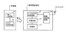
図1は、本発明の処理装置を用いた充電システムの概要を示す図である。 FIG. 1 is a diagram showing an outline of a charging system using the processing apparatus of the present invention.
本発明の充電システムは図1に示すように、処理装置である携帯電話端末1と充電器2とから構成されている。携帯電話端末1は、充電池11と、充電手段となる充電回路12と、電波受信手段となるアンテナ13と、受信状態検出手段となる無線送受信回路14と、第1の制御手段となるベースバンドホスト制御回路15とを有している。また、充電器2は、電力供給手段となる電力供給部21と、第2の制御手段となるホスト制御回路22とを有している。 As shown in FIG. 1, the charging system of the present invention includes a mobile phone terminal 1 and a
上記のように構成された充電システムにおいては、充電器2から供給される電力で携帯電話端末1の充電池11の充電が行われることになる。 In the charging system configured as described above, the
携帯電話端末1においては、アンテナ13にて電波を受信している。そして、無線送受信回路14において、アンテナ13における電波の受信状態を検出する。充電回路12は、充電器2から供給された電力を用いて充電地11に充電を行うが、その制御はベースバンドホスト制御回路15が行う。ベースバンドホスト制御回路15は、充電池11に充電が行われていない状態で無線送受信回路14にて検出された受信状態と、充電池11への充電中に無線送受信回路14にて検出された受信状態とに基づいて、充電回路12による充電池11への充電を制御する。 In the mobile phone terminal 1, the
充電器2においては、電力供給部21から携帯電話端末1に充電池11に充電を行うための電力を供給するが、その制御はホスト制御回路22が行う。 In the
以下に、上記のように構成された充電システムについて具体的な例を挙げて説明する。 Below, a specific example is given and demonstrated about the charging system comprised as mentioned above.
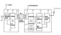
図2は、図1に示した充電システムの実施の一形態を示す図である。 FIG. 2 is a diagram showing an embodiment of the charging system shown in FIG.
本形態は図2に示すように、電波を受信して動作を行う携帯電話端末10と、携帯電話端末10の充電を行う充電器20とから構成されている。 As shown in FIG. 2, this embodiment includes a
携帯電話端末10は、充電池11と、充電回路12と、電波受信手段となるアンテナ13と、受信状態検出手段となる無線送受信回路14と、第1の制御手段となるベースバンドホスト制御回路15と、電源制御回路16と、受電回路17と、受電/信号送信用コイル18とから構成されている。 The
充電回路12は、充電器20から供給された電力を用いて充電池11への充電を行う。 The
アンテナ13は、電波を送受信する。 The
無線送受信回路14は、携帯電話端末10の動作に用いる信号をアンテナ13を介して電波で送受信し、また、アンテナ13における電波の受信状態となる受信感度を検出し、受信感度値をベースバンドホスト制御回路15に出力する。 The radio transmission /
ベースバンドホスト制御回路15は、充電池11に充電が行われていない状態で無線送受信回路14にて検出された第1の受信感度と、充電池11への充電中に無線送受信回路14にて検出された第2の受信感度とに基づいて、充電回路12による充電池11への充電を制御する。具体的には、ベースバンドホスト制御回路15は、無線送受信回路14にて検出されて出力された第1の受信感度と第2の受信感度との差が予め決められた第1の値以上であり、かつ、無線送受信回路14にて検出されて出力された第2の受信感度が予め決められた第2の値以下である場合に、充電池11への充電を制御するための充電器制御信号を受電回路17及び受電/信号送信用コイル18を介して充電器20に出力する。また、ベースバンドホスト制御回路15は、充電回路12による充電池11への充電の停止後、所定時間が経過した場合、またはアンテナ13にて受信する電波の周波数帯域が変化した場合、または携帯電話端末10にて使用するチャネルが変わった場合、充電回路による充電池11への充電が開始されるように、充電器制御信号を受電回路17及び受電/信号送信用コイル18を介して充電器20に出力する。また、ベースバンドホスト制御回路15は、充電池11の充電量が予め決められた量よりも大きな場合、充電器制御信号を充電器20に出力しないことで、充電回路12による充電池11への充電を開始しないように制御する。 The baseband
電源制御回路16は、充電池11に充電された電力を電源として無線送受信回路14及びベースバンドホスト制御回路15に供給する。 The power
受電回路17は、充電器20から供給された電力を受電/信号送信用コイル18を介して受け取り、その電力を充電回路12に与える。 The
充電器20は、電力供給手段となる送電回路23と、第2の制御手段となるホスト制御回路22と、AC/DC電源制御回路24と、送電/信号受信用コイル25と、プラグ26とから構成されている。 The charger 20 includes a
AC/DC電源制御回路24は、コンセントに差し込まれたプラグ26から供給されてくる交流電源を直流電源に変換してホスト制御回路22及び送電回路23に供給する。 The AC / DC power
送電回路23は、AC/DC電源制御回路24から供給された直流電源による電力を送電/信号受信用コイル25を介して携帯電話端末10に供給する。 The
ホスト制御回路22は、携帯電話端末10のベースバンドホスト制御回路15から出力された充電器制御信号に応じて送電回路23からの携帯電話端末10への電力の供給を制御する。 The
以下に、上記のように構成された充電システムにおける携帯電話端末10の充電方法について説明する。 Below, the charge method of the
図3は、図2に示した充電システムにおける携帯電話端末10の充電方法の実施の一形態を説明するためのフローチャートである。 FIG. 3 is a flowchart for explaining an embodiment of a method for charging
携帯電話端末10が充電器20上に置かれていない非充電状態から(ステップ1)、充電器20上に置かれ、携帯電話端末10が充電器20上に置かれたことを判断すると(ステップ2)、まず、ベースバンドホスト制御回路15は、充電器20からの電力の送電を一時停止させるための充電器制御信号を出力する。なお、携帯電話端末10が充電器20上に置かれたと判断することは、例えば、携帯電話端末10と充電器20との通電の検出を用いることが考えられる。本形態のように、充電器20からの携帯電話端末10への電力の供給が、受電/信号送信用コイル18及び送電/信号受信用コイル25を介した無接点充電であるものにおいては、充電器20から供給された電力が受電/信号送信用コイル18を介して携帯電話端末10にて受電された場合に、携帯電話端末10が充電器20上に置かれたと判断することが考えられる。また、物理的な手段によって、携帯電話端末10が充電器20上に置かれたことを判断してもよい。 When the
ベースバンドホスト制御回路15から充電器制御信号が出力されると、受電回路17が、ベースバンドホスト制御回路15から出力された充電器制御信号を受電/信号送信用コイル18を介して充電器20に送信する。 When the charger control signal is output from the baseband
携帯電話端末10から充電器20に送信された充電器制御信号は、充電器20の送電/信号受信用コイル25を介してホスト制御回路22にて受信される。 The charger control signal transmitted from the
すると、ホスト制御回路22は、受信した充電器制御信号に従って、送電回路23からの携帯電話端末10に対する電力の供給を停止させる。それにより、携帯電話端末10は充電器20の上に置かれているものの、充電池11に対して充電が行われていない非充電状態となる。 Then, the
この非充電状態において、携帯電話端末10は、第1の受信状態検出処理として、アンテナ13にて受信される電波の受信感度を無線送受信回路14にて検出する。そして、無線送受信回路14は、検出した電波の受信感度データをベースバンドホスト制御回路15に送り、ベースバンドホスト制御回路15にて非充電時感度値として記憶しておく(ステップ3)。 In this non-charged state, the
その後、携帯電話端末10は、充電池11に充電を行うため、充電器20からの電力の送電を許可する充電器制御信号をベースバンドホスト制御回路15から出力する。 Thereafter, the
ベースバンドホスト制御回路15から充電器制御信号が出力されると、受電回路17が、ベースバンドホスト制御回路15から出力された充電器制御信号を受電/信号送信用コイル18を介して充電器20に送信する。 When the charger control signal is output from the baseband
携帯電話端末10から充電器20に送信された充電器制御信号は、充電器20の送電/信号受信用コイル25を介してホスト制御回路22にて受信される。 The charger control signal transmitted from the
すると、ホスト制御回路22は、受信した充電器制御信号に従って、送電回路23からの携帯電話端末10に対する電力の供給を開始し、この電力が送電/信号受信用コイル25及び受電/信号送信用コイル18を介して受電回路17にて受電される。そして、充電回路12が、受電回路17にて受電された電力を用いて充電地11に試し充電を開始する(ステップ4)。これにより、充電池11に対して充電が行われている充電状態となる。 Then, the
この充電状態において、携帯電話端末10は、第2の受信状態検出処理として、アンテナ13にて受信される電波の受信感度を無線送受信回路14にて検出する。そして、無線送受信回路14は、検出した電波の受信感度データをベースバンドホスト制御回路15に送り、ベースバンドホスト制御回路15にて充電時感度値として記憶する(ステップ5)。 In this charging state, the
ベースバンドホスト制御回路15は、この充電時感度値とステップ3にて記憶した非充電時感度値とを用いて、下記式に基づいて感度劣化値Dを計算する(ステップ6)。 The baseband
感度劣化値D=(非充電時感度値)−(充電時感度値)
そして、ベースバンドホスト制御回路15は、計算した感度劣化値Dが予め決められた第1の値となるD1dB以上であるかどうかを判断する(ステップ7)。Sensitivity deterioration value D = (sensitivity value at non-charging)-(sensitivity value at charging)
Then, the baseband
また、感度劣化値DがD1dB以上である場合は、ベースバンドホスト制御回路15は、充電による感度劣化の影響ありと判断するが、さらに、ステップ5にて記憶した充電時感度値が予め決められた第2の値であるF1dBm以下であるかどうかを判断する(ステップ8)。 If the sensitivity degradation value D is equal to or greater than D1 dB, the baseband
そして、充電感時度値がF1dBm以下であった場合は、ベースバンドホスト制御回路15は、充電器20から発生するノイズが原因となって受信感度が劣化し、その受信、通話が阻害される不具合が発生すると判断し、充電器20からの電力の送電を停止させるための充電器制御信号を出力する。 When the charging time value is less than or equal to F1 dBm, the baseband
ベースバンドホスト制御回路15から充電器制御信号が出力されると、受電回路17が、ベースバンドホスト制御回路15から出力された充電器制御信号を受電/信号送信用コイル18を介して充電器20に送信する。 When the charger control signal is output from the baseband
携帯電話端末10から充電器20に送信された充電器制御信号は、充電器20の送電/信号受信用コイル25を介してホスト制御回路22にて受信される。 The charger control signal transmitted from the
すると、ホスト制御回路22は、受信した充電器制御信号に従って、送電回路23からの携帯電話端末10に対する電力の供給を停止させる。それにより、携帯電話端末10は充電器20の上に置かれているものの、充電池11に対する充電停止状態となり(ステップ9)、充電器20から発生するノイズが抑制される。 Then, the
その後、携帯電話端末10は、一定時間が経過するか、または、通信システム周波数帯域に変化してアンテナ13にて受信する電波の周波数帯域が変化するか、または、携帯電話端末10の使用状態に応じて使用するチャネルが変わるまで、この充電停止状態を維持する(ステップ10)。なお、上述した一定時間においては、この一定時間が周期的に繰り返されても充電池11の充放電サイクル劣化に影響がないほど長い時間間隔とする。 After that, the
充電池11に対する充電停止状態となった後、一定時間が経過するか、または、通信システム周波数帯域に変化してアンテナ13にて受信する電波の周波数帯域が変化するか、または、携帯電話端末10の使用状態に応じて使用するチャネルが変わった場合は、充電器20から発生するノイズによる受信感度の劣化の影響を再評価するため、ステップ3における処理に戻る。 After the charging of the
また、ステップ7における判断において感度劣化値DがD1dB未満であった場合は、ベースバンドホスト制御回路15は、充電器20から発生するノイズが原因となる受信感度の劣化の影響はないと判断し、充電器20からの電力の送電を停止させるための充電器制御信号を出力することはせず、それにより、充電回路12は、充電池11に対する充電を継続して行う(ステップ11)。 If the sensitivity deterioration value D is less than D1 dB in the determination in step 7, the baseband
また、ステップ8における判断において充電感時度値がF1dBmを超えていた場合は、ベースバンドホスト制御回路15は、充電器20から発生するノイズが原因となる受信感度の劣化の影響はあるものの、電波環境が中強電界の環境であるため、携帯電話端末10の受信、通話が阻害される不具合は発生しないと判断し、充電器20からの電力の送電を停止させるための充電器制御信号を出力することはせず、それにより、充電回路12は、ステップ11にて充電池11に対する充電を継続して行う。 Further, when the charge sensitivity value exceeds F1 dBm in the determination in step 8, the baseband
その後、携帯電話端末10は、一定時間が経過するか、または、通信システム周波数帯域に変化してアンテナ13にて受信する電波の周波数帯域が変化するか、または、携帯電話端末10の使用状態に応じて使用するチャネルが変わるまで(ステップ12)、ベースバンドホスト制御回路15が、ステップ5,8における処理と同様に、無線送受信回路14にて検出された充電時の受信感度値を取得し(ステップ13)、その充電時の受信感度値がF1dBm以下であるかどうかを判断する(ステップ14)。 After that, the
そして、充電感時度値がF1dBmを超えている場合は、充電器20から電力が引き続き供給され、充電池11に対する充電が継続される。 When the charge sensation time value exceeds F1 dBm, power is continuously supplied from the charger 20 and charging of the
また、ステップ11にて充電池11に対する充電が継続して行われている状態において、一定時間が経過するか、または、通信システム周波数帯域に変化してアンテナ13にて受信する電波の周波数帯域が変化するか、または、携帯電話端末10の使用状態に応じて使用するチャネルが変わった場合や、充電感時度値がF1dBm以下であった場合は、ステップ9における処理と同様に、ベースバンドホスト制御回路15が、充電器20からの電力の送電を停止させるための充電器制御信号を出力し、これに応じて、送電回路23からの携帯電話端末10に対する電力の供給が停止し、充電池11に対する充電停止状態となる(ステップ15)。そして、充電器20から発生するノイズが原因となる受信感度の劣化の影響を再評価するため、ステップ3における処理に戻る。 In addition, in a state where the charging of the
本形態における携帯電話端末10は、以上説明したように充電器20による充電を行うため、充電動作のノイズによって着信動作や通信動作を致命的に阻害する状況を的確に判断することができ、その場合においてのみ、受信感度劣化による着信動作や通信動作に対する致命的問題を解決することができる。また、充電池11の充放電サイクル劣化による充電池11の使用寿命を短くさせてしまうことを回避することができる。 Since the
(他の実施の形態)
図4は、図2に示した充電システムにおける携帯電話端末10の充電方法の他の実施の形態を説明するためのフローチャートである。(Other embodiments)
FIG. 4 is a flowchart for explaining another embodiment of the method for charging the
本形態における充電方法は、上述した実施の形態にて示したものに対して、上述した充電制御を行う前に、充電池11の充電量を確認し、その充電量が予め決められた量よりも大きな場合に充電制御を行わないようにする点が異なるものである。 The charging method in the present embodiment is to confirm the charge amount of the
本形態においては、携帯電話端末10が非充電状態にて充電器20上に置かれた後(ステップ21,22)、ベースバンドホスト回路15が、充電池11の充電量を確認し(ステップ23)、その充電量が予め決められた量以下である場合にのみ、図3に示したステップ3〜15と同様の充電制御を行う(ステップ24〜36)。 In this embodiment, after the
このように、充電池11の充電量が予め決められた量以下である場合にのみ充電制御を行うことにより、充電状態/非充電状態の切り替え回数を削減し、充電池11の寿命が短くなってしまうことをさらに回避することができる。 In this way, by performing the charge control only when the charge amount of the
また、上述した実施の形態においては、充電器20から供給された電力が、送電/信号受信用コイル25及び受電/信号送信用コイル18を介して携帯電話端末10にて受電される無接点充電方式による充電池11への充電を例に挙げて説明したが、接点方式で充電池11に充電を行うシステムであっても、携帯電話端末10から充電器20による充電状態を制御できるものであれば、本発明を適用することができる。 In the above-described embodiment, the contactless charging in which the power supplied from the charger 20 is received by the
なお、上述したような充電システムは、例えば、WPCに準拠した無接点充電台(トランスミッタ)と無接点充電に対応した携帯端末(レシーバ)からなる無接点充電システムでの携帯電話端末の感度劣化対策に利用することができる。 Note that the charging system as described above is, for example, a countermeasure for sensitivity deterioration of a mobile phone terminal in a non-contact charging system including a WPC-compliant non-contact charging stand (transmitter) and a mobile terminal (receiver) compatible with non-contact charging. Can be used.
また、本発明の処理装置は、電波を受信する動作を行うものであれば、上述したような携帯電話端末に限らず、携帯音楽プレーヤーや携帯ゲーム機、タブレットPCやノートPC等であってもよい。 In addition, the processing apparatus of the present invention is not limited to the above-described mobile phone terminal as long as it performs an operation of receiving radio waves, and may be a portable music player, a portable game machine, a tablet PC, a notebook PC, or the like. Good.
また、本発明においては、携帯電話端末10内の処理は上述の専用のハードウェアに基づいて実現されるもの以外に、その機能を実現するためのプログラムを携帯電話端末10にて読取可能な記録媒体に記録し、この記録媒体に記録されたプログラムを携帯電話端末10に読み込ませ、実行するものであっても良い。携帯電話端末10にて読取可能な記録媒体とは、ICカードやメモリカード、あるいは、フロッピーディスク(登録商標)、光磁気ディスク、DVD、CD等の移設可能な記録媒体の他、携帯電話端末10に内蔵されたHDD等を指す。この記録媒体に記録されたプログラムは、例えば、制御ブロックにて読み込まれ、制御ブロックの制御に基づいて、上述したものと同様の処理が行われる。 In addition, in the present invention, the processing in the
以上、実施例を参照して本願発明を説明したが、本願発明は上記実施例に限定されるものではない。本願発明の構成や詳細には、本願発明のスコープ内で当業者が理解し得る様々な変更をすることができる。 While the present invention has been described with reference to the embodiments, the present invention is not limited to the above embodiments. Various changes that can be understood by those skilled in the art can be made to the configuration and details of the present invention within the scope of the present invention.
この出願は、2011年5月16日に出願された日本出願特願2011−109375を基礎とする優先権を主張し、その開示の全てをここに取り込む。 This application claims the priority on the basis of Japanese application Japanese Patent Application No. 2011-109375 for which it applied on May 16, 2011, and takes in those the indications of all here.
Claims (7)
Translated fromJapanese電波を受信する電波受信手段と、
前記電波受信手段における電波の受信状態を検出する受信状態検出手段と、
前記充電池に充電が行われていない状態で前記受信状態検出手段にて検出された受信状態と、前記充電池への充電中に前記受信状態検出手段にて検出された受信状態とに基づいて、前記充電手段による前記充電池への充電を制御する制御手段とを有する処理装置。A charging means for charging the rechargeable battery;
Radio wave receiving means for receiving radio waves;
Reception state detection means for detecting the reception state of the radio wave in the radio wave reception means;
Based on the reception state detected by the reception state detection means when the rechargeable battery is not charged, and the reception state detected by the reception state detection means during charging of the rechargeable battery And a control unit that controls charging of the rechargeable battery by the charging unit.
前記受信状態検出手段は、前記充電池に充電が行われていない状態における前記受信手段における電波の受信感度となる第1の受信感度と、前記充電池への充電中における前記電波受信手段における電波の受信感度となる第2の受信感度とを検出し、
前記制御手段は、前記第1の受信感度と前記第2の受信感度との差が予め決められた第1の値以上であり、かつ、前記第2の受信感度が予め決められた第2の値以下である場合に、前記充電手段による前記充電池への充電が停止するように制御する処理装置。The processing apparatus according to claim 1,
The reception state detection means includes a first reception sensitivity that is a reception sensitivity of radio waves in the reception means when the rechargeable battery is not charged, and radio waves in the radio wave reception means during charging of the rechargeable battery. Detecting the second receiving sensitivity which is the receiving sensitivity of
The control means is configured such that a difference between the first reception sensitivity and the second reception sensitivity is equal to or greater than a predetermined first value, and the second reception sensitivity is a predetermined second value. The processing apparatus which controls so that the charge to the said rechargeable battery by the said charging means stops when it is below a value.
前記制御手段は、前記充電手段による前記充電池への充電の停止後、所定時間が経過した場合、または前記電波受信手段にて受信する電波の周波数帯域が変化した場合、または前記処理装置にて使用するチャネルが変わった場合、前記充電手段による前記充電池への充電が開始されるように制御する処理装置。The processing apparatus according to claim 2,
The control means may be configured such that when a predetermined time has elapsed after the charging of the rechargeable battery by the charging means has stopped, or when the frequency band of the radio wave received by the radio wave receiving means has changed, or in the processing device A processing device for controlling charging of the rechargeable battery by the charging means when a channel to be used is changed.
前記制御手段は、前記充電池の充電量が予め決められた量よりも大きな場合、前記充電手段による前記充電池への充電を開始しないように制御する処理装置。The processing apparatus according to any one of claims 1 to 3,
The said control means is a processing apparatus which controls not to start charge to the said rechargeable battery by the said charging means, when the charge amount of the said rechargeable battery is larger than the predetermined quantity.
前記処理装置は、
前記充電器から供給される電力を用いて充電池への充電を行う充電手段と、
電波を受信する電波受信手段と、
前記電波受信手段における電波の受信状態を検出する受信状態検出手段と、
前記充電池に充電が行われていない状態で前記受信状態検出手段にて検出された受信状態と、前記充電池への充電中に前記受信状態検出手段にて検出された受信状態とに基づいて、前記充電池への充電を制御するための制御信号を前記充電器に出力する第1の制御手段とを有し、
前記充電器は、
前記処理装置に電力を供給する電力供給手段と、
前記制御手段から出力された制御信号に応じて前記電力供給手段における前記処理装置への電力の供給を制御する第2の制御手段とを有する充電システム。A charging system having a processing device and a charger,
The processor is
Charging means for charging the rechargeable battery using electric power supplied from the charger;
Radio wave receiving means for receiving radio waves;
Reception state detection means for detecting the reception state of the radio wave in the radio wave reception means;
Based on the reception state detected by the reception state detection means when the rechargeable battery is not charged, and the reception state detected by the reception state detection means during charging of the rechargeable battery And a first control means for outputting a control signal for controlling charging to the rechargeable battery to the charger,
The charger is
Power supply means for supplying power to the processing device;
A charging system comprising: second control means for controlling supply of power to the processing device in the power supply means in accordance with a control signal output from the control means.
前記処理装置が、前記充電池に充電が行われていない状態における電波の受信状態を検出する第1の受信状態検出処理と、
前記処理装置が、前記充電池への充電中における電波の受信状態を検出する第2の受信状態検出処理と、
前記処理装置が、前記第1の受信状態検出処理と前記第2の受信状態検出処理にてそれぞれ検出された受信状態に基づいて、前記充電池への充電を制御する充電制御処理とを有する充電方法。A charging method in a processing apparatus including a rechargeable battery,
A first reception state detection process in which the processing device detects a reception state of radio waves in a state where the rechargeable battery is not charged;
A second reception state detection process in which the processing device detects a reception state of radio waves during charging of the rechargeable battery;
Charging including: a charging control process for controlling charging of the rechargeable battery based on the reception states detected by the first reception state detection process and the second reception state detection process, respectively. Method.
前記充電池に充電が行われていない状態における電波の受信状態を検出する第1の受信状態検出手順と、
前記充電池への充電中における電波の受信状態を検出する第2の受信状態検出手順と、
前記第1の受信状態検出手順と前記第2の受信状態検出手順にてそれぞれ検出された受信状態に基づいて、前記充電池への充電を制御する充電制御手順とを実行させるためのプログラム。In a processing device equipped with a rechargeable battery,
A first reception state detection procedure for detecting a reception state of radio waves in a state where the rechargeable battery is not charged;
A second reception state detection procedure for detecting a reception state of radio waves during charging of the rechargeable battery;
A program for executing a charge control procedure for controlling charging of the rechargeable battery based on the reception states detected in the first reception state detection procedure and the second reception state detection procedure, respectively.
Applications Claiming Priority (3)
| Application Number | Priority Date | Filing Date | Title |
|---|---|---|---|
| JP2011109375 | 2011-05-16 | ||
| JP2011109375 | 2011-05-16 | ||
| PCT/JP2012/057429WO2012157337A1 (en) | 2011-05-16 | 2012-03-23 | Processing apparatus, charging system, charging method, and program |
Publications (1)
| Publication Number | Publication Date |
|---|---|
| JPWO2012157337A1true JPWO2012157337A1 (en) | 2014-07-31 |
Family
ID=47176678
Family Applications (1)
| Application Number | Title | Priority Date | Filing Date |
|---|---|---|---|
| JP2013515033APendingJPWO2012157337A1 (en) | 2011-05-16 | 2012-03-23 | Processing apparatus, charging system, charging method and program |
Country Status (4)
| Country | Link |
|---|---|
| US (1) | US20140300313A1 (en) |
| EP (1) | EP2712047A1 (en) |
| JP (1) | JPWO2012157337A1 (en) |
| WO (1) | WO2012157337A1 (en) |
Families Citing this family (4)
| Publication number | Priority date | Publication date | Assignee | Title |
|---|---|---|---|---|
| KR102125507B1 (en)* | 2012-07-02 | 2020-06-23 | 삼성전자주식회사 | Method for charging battery and an electronic device thereof |
| EP3042452B1 (en)* | 2013-08-09 | 2018-10-03 | Intel Corporation | Coil for mobile device context-driven switching and wireless charging |
| KR102126713B1 (en) | 2013-08-13 | 2020-06-25 | 삼성전자주식회사 | Controlling method and apparatus of wireless charging in wireless power transfer system |
| US9407103B2 (en)* | 2014-03-07 | 2016-08-02 | Nissan North America, Inc. | Battery charger noise reduction by variable frequency |
Family Cites Families (7)
| Publication number | Priority date | Publication date | Assignee | Title |
|---|---|---|---|---|
| JP2557408B2 (en)* | 1987-09-14 | 1996-11-27 | 株式会社東芝 | Wireless communication device |
| JPH0787678A (en)* | 1993-09-13 | 1995-03-31 | Casio Comput Co Ltd | Communication device |
| JP4182294B2 (en)* | 2003-07-24 | 2008-11-19 | 京セラ株式会社 | Mobile communication device |
| JP2006340586A (en)* | 2005-06-06 | 2006-12-14 | Nec Access Technica Ltd | Mobile terminal and method for controlling charging of mobile terminal |
| JP2008131812A (en) | 2006-11-22 | 2008-06-05 | Kenwood Corp | Charger for portable radio unit |
| JP2008243001A (en)* | 2007-03-28 | 2008-10-09 | Toshiba Corp | Portable electronic devices |
| JP2011078191A (en)* | 2009-09-30 | 2011-04-14 | Nec Casio Mobile Communications Ltd | Charger, electronic equipment, and program |
- 2012
- 2012-03-23EPEP12785888.4Apatent/EP2712047A1/ennot_activeWithdrawn
- 2012-03-23USUS14/117,526patent/US20140300313A1/ennot_activeAbandoned
- 2012-03-23WOPCT/JP2012/057429patent/WO2012157337A1/enactiveApplication Filing
- 2012-03-23JPJP2013515033Apatent/JPWO2012157337A1/enactivePending
Also Published As
| Publication number | Publication date |
|---|---|
| WO2012157337A1 (en) | 2012-11-22 |
| US20140300313A1 (en) | 2014-10-09 |
| EP2712047A1 (en) | 2014-03-26 |
Similar Documents
| Publication | Publication Date | Title |
|---|---|---|
| US12107443B2 (en) | Electronic device and method for transmission of reason wireless charging is stopping | |
| JP7026646B2 (en) | A wireless power transmission control method in a resonance type wireless power transmission system, a wireless power transmission device using the same, and a wireless power receiving device using the same. | |
| US10651671B2 (en) | Wireless power charging system | |
| CN101919289B (en) | Mobile station device, wireless communication system, mobile station device control method | |
| US9509171B2 (en) | Method and apparatus for optimizing standby power consumption and providing user indications in WPC based wireless charging system | |
| CN104838599B (en) | Parsing is with the communication in the wireless power system of the transmitter in same place | |
| KR101683651B1 (en) | Noise reducing apparatus and method of the wireless charging device | |
| WO2016060988A1 (en) | Audio class-compliant charging accessories for wireless headphones and headsets | |
| JP6231883B2 (en) | Electronic device and electronic device charging system | |
| KR102648609B1 (en) | Electronic device for controlling wireless charging and method for controlling thereof | |
| JP5855968B2 (en) | Mobile communication terminal, communication terminal system, and method for controlling charging by a non-contact charger | |
| CN114128084A (en) | Electronic device and frequency interference elimination method thereof | |
| US8019281B2 (en) | Transmission method and transmission system | |
| US10027156B2 (en) | Electronic apparatus and charging method | |
| WO2012157337A1 (en) | Processing apparatus, charging system, charging method, and program | |
| US20130021003A1 (en) | Communication terminal, charge control program and charge control method | |
| KR101835007B1 (en) | Apparatus and mathod for controlling charge current in portable terminal | |
| US20160197649A1 (en) | Communication system and communication device | |
| JP5732320B2 (en) | Mobile communication terminal and charging system | |
| US10340728B2 (en) | Electronic device and method for charging a battery of the electronic device | |
| KR102237226B1 (en) | Foreign object detection method and apparatus in a wireless power transmission system | |
| JP2012204921A (en) | Electronic equipment | |
| JP2016226076A (en) | Mobile terminal and contactless charger | |
| JP2014103788A (en) | Charger and control program | |
| WO2007001822A2 (en) | Method and apparatus for detecting defective battery cells |