JPWO2012147675A1 - Stent - Google Patents
StentDownload PDFInfo
- Publication number
- JPWO2012147675A1 JPWO2012147675A1JP2013512343AJP2013512343AJPWO2012147675A1JP WO2012147675 A1JPWO2012147675 A1JP WO2012147675A1JP 2013512343 AJP2013512343 AJP 2013512343AJP 2013512343 AJP2013512343 AJP 2013512343AJP WO2012147675 A1JPWO2012147675 A1JP WO2012147675A1
- Authority
- JP
- Japan
- Prior art keywords
- stent
- bulging portion
- stent body
- tubular organ
- axial direction
- Prior art date
- Legal status (The legal status is an assumption and is not a legal conclusion. Google has not performed a legal analysis and makes no representation as to the accuracy of the status listed.)
- Granted
Links
Images


Classifications
- A—HUMAN NECESSITIES
- A61—MEDICAL OR VETERINARY SCIENCE; HYGIENE
- A61F—FILTERS IMPLANTABLE INTO BLOOD VESSELS; PROSTHESES; DEVICES PROVIDING PATENCY TO, OR PREVENTING COLLAPSING OF, TUBULAR STRUCTURES OF THE BODY, e.g. STENTS; ORTHOPAEDIC, NURSING OR CONTRACEPTIVE DEVICES; FOMENTATION; TREATMENT OR PROTECTION OF EYES OR EARS; BANDAGES, DRESSINGS OR ABSORBENT PADS; FIRST-AID KITS
- A61F2/00—Filters implantable into blood vessels; Prostheses, i.e. artificial substitutes or replacements for parts of the body; Appliances for connecting them with the body; Devices providing patency to, or preventing collapsing of, tubular structures of the body, e.g. stents
- A61F2/02—Prostheses implantable into the body
- A61F2/04—Hollow or tubular parts of organs, e.g. bladders, tracheae, bronchi or bile ducts
- A61F2/06—Blood vessels
- A61F2/07—Stent-grafts
- A—HUMAN NECESSITIES
- A61—MEDICAL OR VETERINARY SCIENCE; HYGIENE
- A61F—FILTERS IMPLANTABLE INTO BLOOD VESSELS; PROSTHESES; DEVICES PROVIDING PATENCY TO, OR PREVENTING COLLAPSING OF, TUBULAR STRUCTURES OF THE BODY, e.g. STENTS; ORTHOPAEDIC, NURSING OR CONTRACEPTIVE DEVICES; FOMENTATION; TREATMENT OR PROTECTION OF EYES OR EARS; BANDAGES, DRESSINGS OR ABSORBENT PADS; FIRST-AID KITS
- A61F2/00—Filters implantable into blood vessels; Prostheses, i.e. artificial substitutes or replacements for parts of the body; Appliances for connecting them with the body; Devices providing patency to, or preventing collapsing of, tubular structures of the body, e.g. stents
- A61F2/82—Devices providing patency to, or preventing collapsing of, tubular structures of the body, e.g. stents
- A61F2/86—Stents in a form characterised by the wire-like elements; Stents in the form characterised by a net-like or mesh-like structure
- A61F2/90—Stents in a form characterised by the wire-like elements; Stents in the form characterised by a net-like or mesh-like structure characterised by a net-like or mesh-like structure
- A61F2/91—Stents in a form characterised by the wire-like elements; Stents in the form characterised by a net-like or mesh-like structure characterised by a net-like or mesh-like structure made from perforated sheets or tubes, e.g. perforated by laser cuts or etched holes
- A61F2/915—Stents in a form characterised by the wire-like elements; Stents in the form characterised by a net-like or mesh-like structure characterised by a net-like or mesh-like structure made from perforated sheets or tubes, e.g. perforated by laser cuts or etched holes with bands having a meander structure, adjacent bands being connected to each other
- A—HUMAN NECESSITIES
- A61—MEDICAL OR VETERINARY SCIENCE; HYGIENE
- A61L—METHODS OR APPARATUS FOR STERILISING MATERIALS OR OBJECTS IN GENERAL; DISINFECTION, STERILISATION OR DEODORISATION OF AIR; CHEMICAL ASPECTS OF BANDAGES, DRESSINGS, ABSORBENT PADS OR SURGICAL ARTICLES; MATERIALS FOR BANDAGES, DRESSINGS, ABSORBENT PADS OR SURGICAL ARTICLES
- A61L31/00—Materials for other surgical articles, e.g. stents, stent-grafts, shunts, surgical drapes, guide wires, materials for adhesion prevention, occluding devices, surgical gloves, tissue fixation devices
- A61L31/02—Inorganic materials
- A61L31/022—Metals or alloys
- A—HUMAN NECESSITIES
- A61—MEDICAL OR VETERINARY SCIENCE; HYGIENE
- A61F—FILTERS IMPLANTABLE INTO BLOOD VESSELS; PROSTHESES; DEVICES PROVIDING PATENCY TO, OR PREVENTING COLLAPSING OF, TUBULAR STRUCTURES OF THE BODY, e.g. STENTS; ORTHOPAEDIC, NURSING OR CONTRACEPTIVE DEVICES; FOMENTATION; TREATMENT OR PROTECTION OF EYES OR EARS; BANDAGES, DRESSINGS OR ABSORBENT PADS; FIRST-AID KITS
- A61F2/00—Filters implantable into blood vessels; Prostheses, i.e. artificial substitutes or replacements for parts of the body; Appliances for connecting them with the body; Devices providing patency to, or preventing collapsing of, tubular structures of the body, e.g. stents
- A61F2/82—Devices providing patency to, or preventing collapsing of, tubular structures of the body, e.g. stents
- A61F2/848—Devices providing patency to, or preventing collapsing of, tubular structures of the body, e.g. stents having means for fixation to the vessel wall, e.g. barbs
- A—HUMAN NECESSITIES
- A61—MEDICAL OR VETERINARY SCIENCE; HYGIENE
- A61F—FILTERS IMPLANTABLE INTO BLOOD VESSELS; PROSTHESES; DEVICES PROVIDING PATENCY TO, OR PREVENTING COLLAPSING OF, TUBULAR STRUCTURES OF THE BODY, e.g. STENTS; ORTHOPAEDIC, NURSING OR CONTRACEPTIVE DEVICES; FOMENTATION; TREATMENT OR PROTECTION OF EYES OR EARS; BANDAGES, DRESSINGS OR ABSORBENT PADS; FIRST-AID KITS
- A61F2/00—Filters implantable into blood vessels; Prostheses, i.e. artificial substitutes or replacements for parts of the body; Appliances for connecting them with the body; Devices providing patency to, or preventing collapsing of, tubular structures of the body, e.g. stents
- A61F2/0077—Special surfaces of prostheses, e.g. for improving ingrowth
- A61F2002/009—Special surfaces of prostheses, e.g. for improving ingrowth for hindering or preventing attachment of biological tissue
- A—HUMAN NECESSITIES
- A61—MEDICAL OR VETERINARY SCIENCE; HYGIENE
- A61F—FILTERS IMPLANTABLE INTO BLOOD VESSELS; PROSTHESES; DEVICES PROVIDING PATENCY TO, OR PREVENTING COLLAPSING OF, TUBULAR STRUCTURES OF THE BODY, e.g. STENTS; ORTHOPAEDIC, NURSING OR CONTRACEPTIVE DEVICES; FOMENTATION; TREATMENT OR PROTECTION OF EYES OR EARS; BANDAGES, DRESSINGS OR ABSORBENT PADS; FIRST-AID KITS
- A61F2/00—Filters implantable into blood vessels; Prostheses, i.e. artificial substitutes or replacements for parts of the body; Appliances for connecting them with the body; Devices providing patency to, or preventing collapsing of, tubular structures of the body, e.g. stents
- A61F2/02—Prostheses implantable into the body
- A61F2/04—Hollow or tubular parts of organs, e.g. bladders, tracheae, bronchi or bile ducts
- A61F2/06—Blood vessels
- A61F2/07—Stent-grafts
- A61F2002/072—Encapsulated stents, e.g. wire or whole stent embedded in lining
- A—HUMAN NECESSITIES
- A61—MEDICAL OR VETERINARY SCIENCE; HYGIENE
- A61F—FILTERS IMPLANTABLE INTO BLOOD VESSELS; PROSTHESES; DEVICES PROVIDING PATENCY TO, OR PREVENTING COLLAPSING OF, TUBULAR STRUCTURES OF THE BODY, e.g. STENTS; ORTHOPAEDIC, NURSING OR CONTRACEPTIVE DEVICES; FOMENTATION; TREATMENT OR PROTECTION OF EYES OR EARS; BANDAGES, DRESSINGS OR ABSORBENT PADS; FIRST-AID KITS
- A61F2/00—Filters implantable into blood vessels; Prostheses, i.e. artificial substitutes or replacements for parts of the body; Appliances for connecting them with the body; Devices providing patency to, or preventing collapsing of, tubular structures of the body, e.g. stents
- A61F2/82—Devices providing patency to, or preventing collapsing of, tubular structures of the body, e.g. stents
- A61F2/86—Stents in a form characterised by the wire-like elements; Stents in the form characterised by a net-like or mesh-like structure
- A61F2/90—Stents in a form characterised by the wire-like elements; Stents in the form characterised by a net-like or mesh-like structure characterised by a net-like or mesh-like structure
- A61F2/91—Stents in a form characterised by the wire-like elements; Stents in the form characterised by a net-like or mesh-like structure characterised by a net-like or mesh-like structure made from perforated sheets or tubes, e.g. perforated by laser cuts or etched holes
- A61F2/915—Stents in a form characterised by the wire-like elements; Stents in the form characterised by a net-like or mesh-like structure characterised by a net-like or mesh-like structure made from perforated sheets or tubes, e.g. perforated by laser cuts or etched holes with bands having a meander structure, adjacent bands being connected to each other
- A61F2002/9155—Adjacent bands being connected to each other
- A61F2002/91558—Adjacent bands being connected to each other connected peak to peak
- A—HUMAN NECESSITIES
- A61—MEDICAL OR VETERINARY SCIENCE; HYGIENE
- A61F—FILTERS IMPLANTABLE INTO BLOOD VESSELS; PROSTHESES; DEVICES PROVIDING PATENCY TO, OR PREVENTING COLLAPSING OF, TUBULAR STRUCTURES OF THE BODY, e.g. STENTS; ORTHOPAEDIC, NURSING OR CONTRACEPTIVE DEVICES; FOMENTATION; TREATMENT OR PROTECTION OF EYES OR EARS; BANDAGES, DRESSINGS OR ABSORBENT PADS; FIRST-AID KITS
- A61F2210/00—Particular material properties of prostheses classified in groups A61F2/00 - A61F2/26 or A61F2/82 or A61F9/00 or A61F11/00 or subgroups thereof
- A61F2210/0004—Particular material properties of prostheses classified in groups A61F2/00 - A61F2/26 or A61F2/82 or A61F9/00 or A61F11/00 or subgroups thereof bioabsorbable
- A—HUMAN NECESSITIES
- A61—MEDICAL OR VETERINARY SCIENCE; HYGIENE
- A61F—FILTERS IMPLANTABLE INTO BLOOD VESSELS; PROSTHESES; DEVICES PROVIDING PATENCY TO, OR PREVENTING COLLAPSING OF, TUBULAR STRUCTURES OF THE BODY, e.g. STENTS; ORTHOPAEDIC, NURSING OR CONTRACEPTIVE DEVICES; FOMENTATION; TREATMENT OR PROTECTION OF EYES OR EARS; BANDAGES, DRESSINGS OR ABSORBENT PADS; FIRST-AID KITS
- A61F2230/00—Geometry of prostheses classified in groups A61F2/00 - A61F2/26 or A61F2/82 or A61F9/00 or A61F11/00 or subgroups thereof
- A61F2230/0002—Two-dimensional shapes, e.g. cross-sections
- A61F2230/0028—Shapes in the form of latin or greek characters
- A61F2230/0054—V-shaped
- A—HUMAN NECESSITIES
- A61—MEDICAL OR VETERINARY SCIENCE; HYGIENE
- A61F—FILTERS IMPLANTABLE INTO BLOOD VESSELS; PROSTHESES; DEVICES PROVIDING PATENCY TO, OR PREVENTING COLLAPSING OF, TUBULAR STRUCTURES OF THE BODY, e.g. STENTS; ORTHOPAEDIC, NURSING OR CONTRACEPTIVE DEVICES; FOMENTATION; TREATMENT OR PROTECTION OF EYES OR EARS; BANDAGES, DRESSINGS OR ABSORBENT PADS; FIRST-AID KITS
- A61F2250/00—Special features of prostheses classified in groups A61F2/00 - A61F2/26 or A61F2/82 or A61F9/00 or A61F11/00 or subgroups thereof
- A61F2250/0058—Additional features; Implant or prostheses properties not otherwise provided for
- A61F2250/0059—Additional features; Implant or prostheses properties not otherwise provided for temporary
Landscapes
- Health & Medical Sciences (AREA)
- Life Sciences & Earth Sciences (AREA)
- Veterinary Medicine (AREA)
- Engineering & Computer Science (AREA)
- Biomedical Technology (AREA)
- Public Health (AREA)
- General Health & Medical Sciences (AREA)
- Animal Behavior & Ethology (AREA)
- Heart & Thoracic Surgery (AREA)
- Vascular Medicine (AREA)
- Cardiology (AREA)
- Transplantation (AREA)
- Oral & Maxillofacial Surgery (AREA)
- Gastroenterology & Hepatology (AREA)
- Pulmonology (AREA)
- Physics & Mathematics (AREA)
- Optics & Photonics (AREA)
- Chemical & Material Sciences (AREA)
- Inorganic Chemistry (AREA)
- Surgery (AREA)
- Epidemiology (AREA)
- Media Introduction/Drainage Providing Device (AREA)
- Surgical Instruments (AREA)
Abstract
Translated fromJapaneseDescription
Translated fromJapanese本発明は、例えば、血管、尿管、胆管、気管等の管状器官に留置することにより、管状器官の狭窄や閉塞、動脈瘤の破裂等を防止するステントに関する。 The present invention relates to a stent for preventing stenosis or occlusion of a tubular organ, rupture of an aneurysm, etc. by being placed in a tubular organ such as a blood vessel, a ureter, a bile duct, or a trachea.
近年、血管、尿管、胆管、気管等の人体の管状器官における狭窄部や閉塞部にステントを留置して拡張したり、動脈瘤が生じた箇所にステントを留置して、動脈瘤の破裂を防止したり、等といったステントを用いた治療方法が行われている。 In recent years, stents have been placed and expanded at stenosis or occlusions in human tubular organs such as blood vessels, ureters, bile ducts, and trachea. Treatment methods using stents such as prevention and the like have been performed.
この種のステントは、例えば、カテーテルやシース等の内部に縮径した状態で収容され、その状態で管状器官の所定位置まで移送した後、プッシャ等で押し出すことにより、管状器官の内壁に密接して留置されるようになっている。 This type of stent, for example, is accommodated in a reduced diameter inside a catheter, sheath, etc., and is transferred to a predetermined position of the tubular organ in that state, and then pushed out with a pusher or the like, thereby closely contacting the inner wall of the tubular organ. Are to be detained.
このようにして管状器官内に留置されたステントは、時間の経過に伴って、その内腔が胆汁等の体液によって閉塞してしまうことがあった。この場合、管状器官からステントを取り出して、新しいステントを留置する必要がある。また、治療が終了した場合に、管状器官からステントを取り出したいという要望もある。 As described above, the stent placed in the tubular organ in this way sometimes has its lumen blocked by body fluid such as bile. In this case, it is necessary to remove the stent from the tubular organ and place a new stent. There is also a desire to remove the stent from the tubular organ when treatment is complete.
下記特許文献1には、管状器官内に留置したステントを取出すことができるものとして、ステント製造用合金ワイヤを交差するように編んで多数の菱形空間部を有する中空型円筒状胴体でなり、臓器の内部に挿設されて管路を広げる本体ステントと、生分解性ポリマーで製造された別途の生分解性ポリマーワイヤを互いに交差するように編んで多数の菱形空間部を有する中空型円筒状胴体をなし、その中央部が膨出型に突出した膨出部を有する体内分解性ステントとからなり、前記体内分解性ステントが前記本体ステントの外側面に位置し、前記体内分解性ステントの両端のいずれか一端が本体ステントに連結されて構成される、体内分解性二重構造ステントが記載されている。また、前記膨出部は、体内分解性ステントの全周に亘って、環状に膨出した形状をなしている。 In Patent Document 1 below, a stent placed in a tubular organ can be taken out, and is composed of a hollow cylindrical body having a large number of rhombus spaces knitted so as to cross an alloy wire for stent production. A hollow cylindrical body having a large number of rhombus spaces knitted so as to intersect with each other, a main body stent that is inserted into the inside of the body and expands a duct, and a separate biodegradable polymer wire made of a biodegradable polymer And a biodegradable stent having a bulging portion projecting in a bulging shape at the center thereof, wherein the biodegradable stent is located on the outer surface of the main stent, and is disposed at both ends of the biodegradable stent. A biodegradable dual structure stent is described that is configured with either end connected to a main stent. Moreover, the said bulging part has comprised the shape swelled cyclically | annularly over the perimeter of the biodegradable stent.
そして、管状器官の内壁に体内分解性ステントの膨出部が係止することで、二重構造ステントが管状器官の所定位置に留置される。また、生分解性ポリマーで製造された体内分解性ステントは、体液によって徐々に溶けるようになっている。そのため、体内分解性ステントが溶けてなくなることで、その内側に配置された本体ステントを、管状器官から取り出すことができる。 Then, the bulging portion of the biodegradable stent is locked to the inner wall of the tubular organ, so that the dual structure stent is placed at a predetermined position of the tubular organ. In addition, biodegradable stents made of biodegradable polymers are gradually dissolved by body fluids. Therefore, since the biodegradable stent is not melted, the main body stent arranged on the inner side can be taken out from the tubular organ.
上記特許文献1の二重構造ステントの場合、生分解性ポリマーで製造された体内分解性ステントを利用して、管状器官内に留置しているので、留置期間が長いと、体内分解性ステントが溶けてしまって、管状器官の所定位置から移動する結果となり、長期留置には不向きであった。 In the case of the double-structured stent of the above-mentioned Patent Document 1, since the biodegradable stent manufactured with a biodegradable polymer is used and placed in the tubular organ, if the placement period is long, the biodegradable stent is It melts and results in the tube organ moving from a predetermined position, which is not suitable for long-term placement.
また、管状器官内壁に、体内分解性ステントの全周に亘って設けられた環状の膨出部が係止するようになっているので、管状器官に対する体内分解性ステントの係止力が過度に高く、体内分解性ステントが溶けきる前の短期間で、二重構造ステントを管状器官から取り出すことは難しいと考えられる。 Further, since the annular bulging portion provided over the entire circumference of the biodegradable stent is locked to the inner wall of the tubular organ, the locking force of the biodegradable stent with respect to the tubular organ is excessive. It is expensive and it is considered difficult to remove the dual structure stent from the tubular organ in a short period before the biodegradable stent melts.
したがって、本発明の目的は、管状器官の所定位置に位置ずれなく、長期に亘って正確に留置することができると共に、所望の時期に管状器官内からスムーズに取り出すことができる、ステントを提供することにある。 Accordingly, an object of the present invention is to provide a stent that can be accurately placed over a long period of time without being displaced at a predetermined position of the tubular organ and can be smoothly taken out from the tubular organ at a desired time. There is.
上記目的を達成するため、本発明のステントは、管状器官内に留置されるものであって、金属製のステント本体と、このステント本体の外周の少なくとも一部を覆う樹脂製のカバー部材と、前記ステント本体の外周の、前記カバー部材により覆われた部分に設けられ、前記管状器官の内壁に密接してステントの移動を抑制する膨出部とを備え、前記膨出部は、周方向に所定幅でかつ軸方向に所定長さで伸びると共に、次第に盛り上がり次第に低くなるように滑らかに突出した形状をなすことを特徴とする。 To achieve the above object, the stent of the present invention is placed in a tubular organ, and is made of a metal stent body, and a resin cover member covering at least a part of the outer periphery of the stent body. A bulging portion that is provided on a portion of the outer periphery of the stent body that is covered with the cover member and that restrains the movement of the stent in close contact with the inner wall of the tubular organ. It has a predetermined width and a predetermined length in the axial direction, and has a shape that protrudes smoothly so as to gradually rise and gradually lower.
本発明のステントにおいては、前記膨出部は、前記ステント本体の周方向に沿って所定間隔で複数箇所に、かつ、軸方向に沿っても所定間隔で複数箇所に配置されており、各膨出部がステント本体の端面から軸方向に見たとき重ならない位置に配置されていることが好ましい。 In the stent of the present invention, the bulging portions are disposed at a plurality of locations at predetermined intervals along the circumferential direction of the stent body, and at a plurality of locations at predetermined intervals along the axial direction. It is preferable that the protruding portion is disposed at a position where it does not overlap when viewed in the axial direction from the end face of the stent body.
本発明のステントにおいては、前記膨出部は、前記ステント本体の周方向に沿った幅よりも軸方向に沿った長さの方が、大きくなるように形成されていることが好ましい。 In the stent of the present invention, it is preferable that the bulging portion is formed so that the length along the axial direction is larger than the width along the circumferential direction of the stent body.
本発明のステントにおいては、前記膨出部の内側には、空隙が形成されていることが好ましい。 In the stent of the present invention, it is preferable that a void is formed inside the bulging portion.
本発明のステントにおいては、前記膨出部の前記ステント本体の軸方向に沿った傾斜は、最頂部に対してステントの抜き出し方向となる斜面の傾斜が、その反対側の斜面の傾斜よりも緩やかになるように形成されていることが好ましい。 In the stent according to the present invention, the slope of the bulging portion along the axial direction of the stent body is such that the slope of the slope in the stent extraction direction is gentler than the slope of the slope on the opposite side. It is preferable that it is formed so that.
本発明によれば、カテーテルやシース等を介して管状器官内にステントを留置すると、膨出部が管状器官の内壁に密接するので、ステントの位置ずれを抑制して、管状器官の所定位置に正確に留置することができる。また、膨出部は、次第に盛り上がり次第に低くなるように滑らかに突出した形状をなすので、ステントを取り出す必要が生じた場合でも、管状器官を損傷することなく、比較的スムーズに抜き出すことができる。 According to the present invention, when the stent is placed in the tubular organ through a catheter, a sheath, or the like, the bulging portion is in close contact with the inner wall of the tubular organ, so that the displacement of the stent is suppressed and the tubular organ is placed in a predetermined position. It can be placed accurately. Further, since the bulging portion has a shape that protrudes smoothly so as to gradually rise and gradually lower, even when it becomes necessary to take out the stent, it can be extracted relatively smoothly without damaging the tubular organ.
以下、図1〜8を参照して、本発明のステントの一実施形態について説明する。 Hereinafter, an embodiment of the stent of the present invention will be described with reference to FIGS.
図1及び図2に示すように、この実施形態におけるステント10は、金属製のステント本体20と、このステント本体20の外周の少なくとも一部を覆う樹脂製のカバー部材30と、前記ステント本体20の外周の、前記カバー部材30により覆われる部分に設けられ、管状器官の内壁に密接してステント10の移動を抑制する膨出部40とを有している。 As shown in FIGS. 1 and 2, the
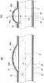
この実施形態の場合、前記ステント本体20は、金属円筒を加工して形成されている。すなわち、図1及び図3(a)に示すように、金属円筒がレーザー加工やエッチング等で加工され、ジグザグ状をなし環状に連結された周方向単位23が形成され、この周方向単位23の屈曲部どうしが連結部25を介して連結されて、複数の周方向単位23が軸方向に配設され、略円筒状のステント本体20が構成されている。 In the case of this embodiment, the
また、ステント本体20としては、図3(b)に示すように、金属円筒が加工され、複数の枠状体22が周方向に連結されてなる周方向単位23が、複数の連結部25を介して軸方向に連結されて、筒状に構成されたものなどであってもよい。 In addition, as shown in FIG. 3B, the
更に、ステント本体20としては、金属線材を織ったり、組んだり、絡ませたり等して、金属線材を編んで筒状に形成されたものを用いることもできる。 Furthermore, the
上記ステント本体20の材質は、特に限定されないが、例えば、ステンレス、Ta、Ti、Pt、Au、W等や、Ni−Ti系合金、Co−Cr系合金、Co−Cr−Ni系合金、Cu−Zn−X(X=Al,Fe等)合金、Ni−Ti−X(X=Fe,Cu,V,Co等)合金等の形状記憶合金などを好ましく用いることができる。 The material of the
なお、上記の形状記憶合金を採用した場合には、金属円筒を拡径させた状態で形状記憶処理を施すことで、変態点以上の温度で拡径した状態となる自己拡張型のステント本体20を得ることができる。なお、ステント本体20はバルーンカテーテルで拡径させるバルーン拡径型のものであってもよい。 When the shape memory alloy is used, a self-expanding
図1、2、4、6に示すように、この実施形態における樹脂製のカバー部材30は、前記ステント本体20の外周に配置される外側カバー31と、同ステント本体20の内周に配置される内側カバー33とからなる。各カバー31,33は、ステント本体20の全長に亘って形成された円筒状をなしており、これらのカバー31,33により、ステント本体20の外周及び内周の全体が覆われるようになっている。 As shown in FIGS. 1, 2, 4, and 6, the
この各カバー31,33の材質としては、例えば、ポリウレタン、シリコーン、天然ゴム、ナイロンエラストマー、ポリエーテルブロックアミド、ポリエチレン、ポリ塩化ビニル、酢酸ビニルや、更には、ポリテトラフルオロエチレン(PTFE)、パーフルオロアルコキシ樹脂(PFA)、四フッ化エチレン−六フッ化プロピレン共重合体(FEP)、四フッ化エチレン−エチレン共重合体(ETFE)等のフッ素系樹脂などを好ましく用いることができる。また、各カバー31,33の更に外周に、ポリブタジエン、スチレン系エラストマー、シリコーン等をコーティングしておくと、加水分解しやすいポリウレタン、ナイロンエラストマー等を保護することができるので好ましい。 Examples of the material of the
ステント本体20の外周には突出部27が突設されており(図1参照)、このステント本体20に樹脂製のカバー部材30が覆われることによって、ステント本体20の外周の外側カバー31により覆われた部分に、ステント本体20の周方向に所定幅でかつ軸方向に所定長さで伸びると共に、次第に盛り上がり次第に低くなるように滑らかに突出した形状をなす膨出部40が設けられるようになっている。すなわち、ステント本体20の外周を覆う樹脂製のカバー部材30の外側カバー31も、前記突出部27によりカバー部材30が内側から押し出され、突出部27の形状に沿って膨出した形状をなしている。以下の説明では、ステント本体20の突出部27とその表面を覆う外側カバー31の膨出した部分とを併せて、膨出部40として説明する。 A
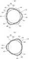
この実施形態では、前記膨出部40は、ステント本体20の周方向に沿って所定間隔で複数箇所に、かつ、軸方向に沿っても所定間隔で複数箇所に配置されており、各膨出部40がステント本体20の端面から軸方向に見たとき重ならない位置に配置されている。具体的には、図2及び図4(a),(b)に示すように、ステント本体20の軸方向一端寄りの箇所に、周方向に均等な間隔で3つの膨出部40が配置されていると共に、ステント本体20の軸方向他端寄りの箇所に、一端寄りの箇所に設けられた膨出部40に重ならないように、周方向に均等な間隔で3つの膨出部40が配置されている。 In this embodiment, the bulging
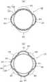
また、図8(a)に示すように、ステント本体20の周方向に対向する箇所に膨出部40,40を設けたり、図8(b)に示すようにステント本体20の周方向に均等な間隔で4つの膨出部40をそれぞれ設けたりしてもよく、これ以上の数の膨出部40を設けてもよい。なお、膨出部40は、ステント本体20の軸方向に所定間隔で複数箇所に設けられることが好ましく、その場合も、図8(a),(b)に示すように、ステント本体20を軸方向端面から見たとき、各膨出部40が重ならない位置に配置されていることが好ましい。 Further, as shown in FIG. 8 (a), bulging
そして、この実施形態における膨出部40は、図2及び図5(a)に示すように、軸方向先端側が尖った先細形状をなすと共に、両側縁43,43が曲線を描きながら軸方向基端側に向けて次第に幅広となるように拡径した、略水滴形状に形成されている。この膨出部40は、先細形状をなす先端側が、ステント10を抜き出すときに抜き出し方向となるように配置される。 As shown in FIGS. 2 and 5 (a), the bulging
図2、図5(b)及び図6に示すように、膨出部40の、ステント本体20の軸方向に沿った部分は、先端側から次第に高く盛り上がって最頂部45(ステント本体20の外周に対して最も高く突出した部分)に至り、この最頂部45から基端側に向けて次第に低くなる形状をなしている。また、図2及び図4(a),(b)に示すように、膨出部40の、ステント本体20の周方向に沿った部分も、周方向一端側から次第に高く盛り上がって最頂部45に至り、最頂部45から周方向他端側に向けて次第に低くなる形状をなしている。そのため、膨出部40は、その周面に角部やエッジ部等のない、全体として滑らかに膨出した形状となっている。 As shown in FIGS. 2, 5 (b), and 6, the portion of the bulging
また、図5(b)及び図6に示すように、膨出部40の、ステント本体20の軸方向に沿った傾斜は、最頂部45に対してステント10の抜き出し方向の斜面、すなわち、先細形状をなした軸方向先端から最頂部45に至るまでの斜面47の傾斜が、その反対側の斜面、すなわち、最頂部45から軸方向基端までの斜面49よりも緩やかになるように形成されている。 Further, as shown in FIGS. 5B and 6, the inclination of the bulging
図5(a)に示すように、膨出部40の、ステント本体20の周方向に沿った幅Wは、ステント本体20の外径Dに対して、5〜60%で形成されていることが好ましく、10〜40%で形成されていることがより好ましい。膨出部40の幅Wがステント本体20の外径Dに対して5%未満の場合は、管状器官の内壁の周方向に対する膨出部40の接触面積が小さく、ステント10が移動しやすくなる傾向があり、幅Wがステント本体20の外径Dに対して60%を超える場合は、管状器官の内壁に対する膨出部40の接触面積が大きすぎて、管状器官内からステント10を取り出しにくくなる傾向がある。 As shown to Fig.5 (a), the width W along the circumferential direction of the stent
また、図5(a)に示すように、膨出部40の、ステント本体20の軸方向に沿った長さLは、前記膨出部40の幅Wよりも大きく形成されていることが好ましい。具体的には、膨出部40の長さLは、膨出部40の幅Wに対して、120〜400%で形成されていることが好ましく、150〜300%で形成されていることがより好ましい。膨出部40の長さLが幅Wに対して120%未満の場合は、ステント10が管状器官の中で移動しやすくなる傾向があり、長さLが幅Wに対して400%を超える場合は、ステント10の柔軟性が低下する傾向がある。 Further, as shown in FIG. 5A, the length L of the bulging
図5(a)に示すように、膨出部40の軸方向先端側の先細部分の角度、すなわち、膨出部40の軸方向先端側における、一方の側縁43に対する他方の側縁43の角度θは、10〜50°であることが好ましく、20〜45°であることがより好ましい。前記θが10°未満の場合は、膨出部40の幅を確保しにくくなり、50°を超える場合は、管状器官内からステント10を取り出すときに抵抗となる傾向がある。 As shown in FIG. 5A, the angle of the tapered portion on the distal end side in the axial direction of the bulging
更に図5(b)に示すように、膨出部40の最頂部45の、ステント本体20の外周からの高さHは、ステント本体20の外径Dに対して、10〜40%で形成されていることが好ましく、15〜30%で形成されていることがより好ましい。膨出部40の最頂部45の高さHがステント本体20の外径Dに対して10%未満の場合は、管状器官内壁に対するアンカー効果が低くなる傾向があり、高さHがステント本体20の外径Dに対して40%を超える場合は、管状器官内壁に膨出部40が強く密接して、管状器官内からステント10を取り出しにくくなる可能性がある。 Further, as shown in FIG. 5 (b), the height H of the
更に、図6に示すように、膨出部40の内側に空隙51が形成されている。この実施形態では、ステント本体20の内周に内側カバー33が配置されているので、この内側カバー33と膨出部40と間に空隙51が形成されている。 Furthermore, as shown in FIG. 6, a
次に上記構造からなるステント10の使用方法の一例について説明する。 Next, an example of a method for using the
図7に示すように、十二指腸V1からは胆管V2や膵管V3が分岐して伸びているが、この実施形態では、胆管V2にステント10を留置する場合について説明する。なお、本発明のステント10は、上記胆管V2以外にも、気管、食道、大腸、血管等の管状器官に留置することもでき、適用する管状器官は特に限定されるものではない。 As shown in FIG. 7, the bile duct V2 and the pancreatic duct V3 branch and extend from the duodenum V1, but in this embodiment, a case where the
まず、ステント10を縮径させて、カテーテルやシース等の図示しない医療用チューブの先端部内周に収容する。このとき、膨出部40の軸方向先端側の先細部分を、医療用チューブの基端側(手元側)に向け、膨出部40の軸方向他端側の拡径部分を、医療用チューブの先端側に向けて、ステント10を医療用チューブの先端部内周に収容する。 First, the diameter of the
そして、周知の方法によって、図示しない内視鏡を口腔や胃等を通して十二指腸V1まで移動させて、内視鏡のルーメンを通して、図示しないガイドワイヤを胆管V2に導入し、その先端部を、胆管V2の狭窄した患部をやや通り越えた位置に到達させる。その後、ガイドワイヤを介して、ステント10を収容した医療用チューブを搬送し、その先端部を胆管V2の患部に到達させる。その状態で医療用チューブからガイドワイヤを引き抜いて、医療用チューブ内にプッシャ等を挿入し、このプッシャ等を介して医療用チューブの先端からステント10を押し出すことで、図7に示すようにステント10が拡径する。 Then, an endoscope (not shown) is moved to the duodenum V1 through the oral cavity, stomach or the like by a well-known method, a guide wire (not shown) is introduced into the bile duct V2 through the lumen of the endoscope, and the distal end thereof is connected to the bile duct V2. To reach a position slightly beyond the constricted affected area. Thereafter, the medical tube containing the
その結果、胆管V2の狭窄した患部がステント10により押し広げられると共に、胆管V2の内壁にステント10の外周が密接し、各膨出部40が胆管V2の内壁に入り込む。このように、本実施形態では胆管V2にステント10を留置することで、胆管V2の内壁にステント10の膨出部40が入り込んで密接するようになっているので、ステント10の位置ずれを抑制して、胆管V2の患部に正確に留置することができる。なお、ステント10は、その一端部を胆管V2の開口からやや突出するように留置することが好ましい(図7参照)。 As a result, the affected part of the bile duct V2 narrowed is expanded by the
このとき、本発明のステント10は、特許文献1の二重構造ステントのように、体内分解性ステントによって管状器官内に留置させる構造とはなっていないので、管状器官内に長期に亘って位置ずれすることなく安定して留置させることができる。 At this time, since the
また、この実施形態では、各膨出部40は、ステント本体20の外周の周方向及び軸方向に所定間隔をおいて複数箇所に配置されているので、バランスよく均一な固定力を付与することができる。更に、図2、図4(a)、及び図7に示すように、膨出部40は、ステント本体20を軸方向端部から見たときに、重ならない位置に配置されているので、ステント10の軸方向移動をより効果的に防止することができる。 Moreover, in this embodiment, since each bulging
そして、ステント10の内腔が胆汁等の体液で閉塞されたり、治療が終了したりして、管状器官からステント10を取り出したい場合には、例えば、ステント10の、胆管V2の開口から突出した部分(図7参照)や、ステント10の所定箇所を、医療用スネアや医療療用クランプ等で把持して、ステント10を引張って胆管V2から抜き出して、十二指腸V1まで移動させた後、カテーテル等を通して引き抜くことで、ステント10を体内から取り出すことができる。 When the lumen of the
このとき、このステント10においては、膨出部40が次第に盛り上がり次第に低くなるように滑らかに突出した形状をなしているので、ステント10が引張られて、膨出部40が胆管V2の内壁に密着しつつ移動しても、胆管V2の内壁の損傷が防止されて、胆管V2から比較的スムーズに抜き出すことができる。 At this time, in the
また、この実施形態では、ステント本体20の外周に外側カバー31が配置されているので、胆管V2の内壁に、ステント本体20が直接密着することが防止されて、ステント本体20の網目間に管状器官内壁が食い込むことを防止することができ、ステント10を管状器官内から抜き出しやすくすることができる。更に、ステント本体20の内周にも内側カバー33が配置されているので、ステント本体20の網目間に、胆汁等の体液が入り込むのを防止することができると共に、流動抵抗を少なくすることができる。 Further, in this embodiment, since the
更に、前記膨出部40は、その内側に空隙51が形成されているので、胆管V2内からステント10を抜き出すべく、ステント10を引張る際に膨出部40が変形しやすくなり、胆管V2からステント10をよりスムーズに抜き出すことができる。 Furthermore, since the void 51 is formed inside the bulging
また、前記膨出部40の、前記ステント本体20の軸方向に沿った傾斜は、最頂部45に対してステント10の抜き出し方向となる斜面47の傾斜が、その反対側の斜面49の傾斜よりも緩やかになるように形成されているので(図5(b)参照)、ステント10を胆管V2から抜き出すときに、膨出部40が胆管V2の内壁に引っ掛かることなく、その内壁に密着しつつ滑るようにして移動させることができ、胆管V2からステント10を、より一層スムーズに抜き出すことができる。 In addition, the slope of the bulging
更に、図5(a)に示すように、この実施形態における膨出部40は、ステント本体20の周方向に沿った幅Wよりも軸方向に沿った長さLの方が、大きくなるように形成されているので、管状器官内壁に対する膨出部40の接触面積を軸方向になるべく大きく確保して、その固定力を高めることができると共に、管状器官内からステント10を抜き出す際には、軸方向に長い膨出部40によって、環状紀堅管状器官の損傷を防ぎつつスムーズに抜き出すことができる。 Furthermore, as shown in FIG. 5A, the bulging
図9には、本発明のステントの他の実施形態について説明する。なお、前記実施形態と実質的に同一部分には同符号を付してその説明を省略する。 FIG. 9 illustrates another embodiment of the stent of the present invention. Note that substantially the same parts as those of the above-described embodiment are denoted by the same reference numerals, and description thereof is omitted.
この実施形態のステント10aは、膨出部40aの形状が前記実施形態と異なっている。図9に示すように、この実施形態における膨出部40aは、ステント本体20の軸方向に沿った長さが周方向に沿った幅よりも大きく形成され、最頂部45に向けて次第に高く盛り上がる軸方向先端側の斜面47と、最頂部45から次第に低くなる軸方向基端側の斜面49とが、同一半径の円弧状をなすと共に、その下部周縁44が楕円状をなしており、全体として略楕円形状となるように滑らかに膨出した形状となっている。 In the
また、前記膨出部40aは、ステント本体20の軸方向一端寄りの箇所に、周方向に均等な間隔で3つの膨出部40aが配置され、ステント本体20の軸方向他端寄りの箇所に、一端寄りの箇所に設けられた膨出部40aに重ならないように、周方向に均等な間隔で3つの膨出部40が配置されている。なお、前記実施形態と同様に、ステント本体20の周方向に対向する箇所に膨出部40aを設けたり、ステント本体20の周方向に均等な間隔で4つの膨出部40aを設けたり、或いはこれ以上の数の膨出部40aを設けたりしてもよい。 In addition, the bulging
また、略楕円形状をなした膨出部40aは、ステント本体20の軸方向に沿った断面形状が円弧状をなすことが好ましい。この場合、円弧の半径は、次のように定めることが好ましい。すなわち、図10(a)に示すように、ステント本体20の膨出部40aの頂点とステント本体20の軸心Cとの距離を半径Rで表したとき、該半径Rよりも大きな半径R1を有する円弧状としたり(膨出部40b)、同図(b)に示すように、該半径Rよりも小さな半径R2を有する円弧状としたり(膨出部40c)、あるいは該半径Rを有する円弧状としたりすることが好ましく、該半径Rよりも大きな半径R1の円弧をなす形状とすることがより好ましい。 Moreover, it is preferable that the cross-sectional shape along the axial direction of the stent
10,10a ステント
20 ステント本体
30 カバー部材
40,40a,40b,40c 膨出部
47,49 斜面
51 空隙10,
Claims (5)
Translated fromJapanese金属製のステント本体と、このステント本体の外周の少なくとも一部を覆う樹脂製のカバー部材と、前記ステント本体の外周の、前記カバー部材により覆われた部分に設けられ、前記管状器官の内壁に密接してステントの移動を抑制する膨出部とを備え、
前記膨出部は、周方向に所定幅でかつ軸方向に所定長さで伸びると共に、次第に盛り上がり次第に低くなるように滑らかに突出した形状をなすことを特徴とするステント。A stent placed in a tubular organ,
A metal stent body, a resin cover member covering at least a part of the outer periphery of the stent body, and a portion of the outer periphery of the stent body covered by the cover member, are provided on the inner wall of the tubular organ. With a bulging portion that closely restrains the movement of the stent,
The bulging portion has a predetermined width in the circumferential direction and a predetermined length in the axial direction, and has a shape that protrudes smoothly so as to gradually rise and gradually lower.
Priority Applications (1)
| Application Number | Priority Date | Filing Date | Title |
|---|---|---|---|
| JP2013512343AJP5795364B2 (en) | 2011-04-27 | 2012-04-23 | Stent |
Applications Claiming Priority (4)
| Application Number | Priority Date | Filing Date | Title |
|---|---|---|---|
| JP2011098892 | 2011-04-27 | ||
| JP2011098892 | 2011-04-27 | ||
| PCT/JP2012/060825WO2012147675A1 (en) | 2011-04-27 | 2012-04-23 | Stent |
| JP2013512343AJP5795364B2 (en) | 2011-04-27 | 2012-04-23 | Stent |
Publications (2)
| Publication Number | Publication Date |
|---|---|
| JPWO2012147675A1true JPWO2012147675A1 (en) | 2014-07-28 |
| JP5795364B2 JP5795364B2 (en) | 2015-10-14 |
Family
ID=47072194
Family Applications (1)
| Application Number | Title | Priority Date | Filing Date |
|---|---|---|---|
| JP2013512343AExpired - Fee RelatedJP5795364B2 (en) | 2011-04-27 | 2012-04-23 | Stent |
Country Status (4)
| Country | Link |
|---|---|
| EP (1) | EP2702964B1 (en) |
| JP (1) | JP5795364B2 (en) |
| CN (1) | CN103547238B (en) |
| WO (1) | WO2012147675A1 (en) |
Families Citing this family (22)
| Publication number | Priority date | Publication date | Assignee | Title |
|---|---|---|---|---|
| CA3009244C (en) | 2009-06-23 | 2020-04-28 | Endospan Ltd. | Vascular prostheses for treating aneurysms |
| CN103945793B (en) | 2011-12-06 | 2016-05-04 | 俄奥梯科创新有限公司 | For device and the using method thereof of repairing in aorta lumen |
| US9993360B2 (en) | 2013-01-08 | 2018-06-12 | Endospan Ltd. | Minimization of stent-graft migration during implantation |
| EP2967930B1 (en)* | 2013-03-13 | 2018-11-28 | Boston Scientific Scimed, Inc. | Anti-migration tissue anchoring system for a fully covered stent |
| WO2014150130A1 (en)* | 2013-03-15 | 2014-09-25 | Merit Medical Systems, Inc. | Esophageal stent |
| US20160270934A1 (en)* | 2013-03-18 | 2016-09-22 | Piolax Medical Devices, Inc. | Stent |
| EP2987464B1 (en)* | 2013-04-18 | 2018-08-22 | National University Corporation Yamagata University | Stent to be placed in bile duct and process for producing same |
| JP5939642B2 (en)* | 2013-05-02 | 2016-06-22 | 日本ライフライン株式会社 | Stent |
| CN105407836B (en)* | 2013-05-23 | 2018-10-02 | 恩都思潘有限公司 | Aorta ascendens holder implanting body system |
| CN105979913B (en) | 2013-06-05 | 2018-09-14 | 俄奥梯科创新有限公司 | Variable sunken holder(VDS)It is grafted component with waveform |
| WO2016054536A1 (en)* | 2014-10-02 | 2016-04-07 | Boston Scientific Scimed, Inc. | Controlled ingrowth feature for antimigration |
| CN106029005B (en) | 2014-12-18 | 2018-01-19 | 恩都思潘有限公司 | The Endovascular stent-graft of horizontal conduit with tired resistance |
| KR101664009B1 (en)* | 2015-02-26 | 2016-10-10 | 전북대학교산학협력단 | Anti migration stent for non vascular and manufacturing method thereof |
| WO2018049111A1 (en)* | 2016-09-09 | 2018-03-15 | W. L. Gore & Associates, Inc. | Total arch concept |
| CN106420126A (en)* | 2016-10-31 | 2017-02-22 | 中山大学附属第医院 | Blood vessel support |
| CN106618817A (en)* | 2016-12-23 | 2017-05-10 | 首都医科大学附属北京儿童医院 | 3D printing endotracheal stent for babies and preparation method and application thereof |
| JP6901869B2 (en)* | 2017-02-27 | 2021-07-14 | 川澄化学工業株式会社 | Covered stent |
| CN108720971A (en)* | 2018-01-28 | 2018-11-02 | 杭州市第人民医院 | A kind of controllable antibacterial trachea bracket |
| US11583393B2 (en) | 2018-12-05 | 2023-02-21 | Acclarent, Inc. | Apparatus and method to maintain patency of dilated anatomical opening |
| WO2021146021A1 (en) | 2020-01-13 | 2021-07-22 | Boston Scientific Scimed, Inc. | Anti-migration stent |
| CN111643220B (en)* | 2020-07-06 | 2025-09-12 | 中南大学湘雅二医院 | A bionic composite artificial trachea and its preparation method |
| WO2023241306A1 (en)* | 2022-06-15 | 2023-12-21 | 微创神通医疗科技(上海)有限公司 | Vascular stent |
Family Cites Families (12)
| Publication number | Priority date | Publication date | Assignee | Title |
|---|---|---|---|---|
| JP2000167063A (en)* | 1998-12-04 | 2000-06-20 | Yuichi Mori | Stent and stent graft |
| US6319278B1 (en)* | 2000-03-03 | 2001-11-20 | Stephen F. Quinn | Low profile device for the treatment of vascular abnormalities |
| US7226474B2 (en)* | 2000-05-01 | 2007-06-05 | Endovascular Technologies, Inc. | Modular graft component junctions |
| US20040015224A1 (en)* | 2002-07-22 | 2004-01-22 | Armstrong Joseph R. | Endoluminal expansion system |
| CN100352406C (en)* | 2004-08-17 | 2007-12-05 | 微创医疗器械(上海)有限公司 | Combined membrane-covered stent capable of being bent in any direction |
| CN100594014C (en)* | 2005-12-23 | 2010-03-17 | 温宁 | Stent valve with radially protruding structure and braiding method for the stent |
| CN2910150Y (en)* | 2006-04-27 | 2007-06-13 | 南京微创医学科技有限公司 | Non-blood vessel coated stand able to prevent complication |
| CN2925418Y (en)* | 2006-05-20 | 2007-07-25 | 张丽云 | Improved gullet stand |
| KR100826664B1 (en)* | 2006-11-01 | 2008-05-02 | 주식회사 엠아이텍 | Stent and method of manufacturing the stent |
| CA2714062A1 (en)* | 2008-01-24 | 2009-07-30 | Medtronic, Inc. | Stents for prosthetic heart valves |
| CN101283937B (en)* | 2008-05-21 | 2010-08-18 | 微创医疗器械(上海)有限公司 | Overlay film frame with an opening and bonding method of the overlay film frame |
| CN201227338Y (en)* | 2008-07-31 | 2009-04-29 | 上海交通大学 | Anti-skid cardia bracket |
- 2012
- 2012-04-23EPEP12776498.3Apatent/EP2702964B1/ennot_activeNot-in-force
- 2012-04-23CNCN201280020779.2Apatent/CN103547238B/ennot_activeExpired - Fee Related
- 2012-04-23WOPCT/JP2012/060825patent/WO2012147675A1/enactiveApplication Filing
- 2012-04-23JPJP2013512343Apatent/JP5795364B2/ennot_activeExpired - Fee Related
Also Published As
| Publication number | Publication date |
|---|---|
| CN103547238B (en) | 2016-01-20 |
| JP5795364B2 (en) | 2015-10-14 |
| CN103547238A (en) | 2014-01-29 |
| EP2702964B1 (en) | 2017-07-19 |
| WO2012147675A1 (en) | 2012-11-01 |
| EP2702964A1 (en) | 2014-03-05 |
| EP2702964A4 (en) | 2015-02-18 |
Similar Documents
| Publication | Publication Date | Title |
|---|---|---|
| JP5795364B2 (en) | Stent | |
| US10952878B2 (en) | Methods and systems for increasing a density of a region of a vascular device | |
| JP5575327B2 (en) | Stent | |
| JP5813230B2 (en) | Stent | |
| JP5719327B2 (en) | Helical stent | |
| JP5921682B2 (en) | Stent | |
| JP6353933B2 (en) | Stent | |
| KR20160079078A (en) | Endoluminal device | |
| CN107106310A (en) | Support with flexible hinge | |
| JP6458165B2 (en) | Stent | |
| WO2014148122A1 (en) | Stent | |
| CN111356420B (en) | Non-invasive spacer bracket | |
| US20200146701A1 (en) | Intraluminal foreign object capturing tool | |
| JP6199181B2 (en) | Stent | |
| JP6605907B2 (en) | Stent | |
| JP7490922B2 (en) | Stents | |
| JP2017070406A (en) | Stent | |
| JP6925869B2 (en) | Stent | |
| JPWO2020045315A1 (en) | Gastrointestinal stent | |
| JP2007125274A (en) | Stent |
Legal Events
| Date | Code | Title | Description |
|---|---|---|---|
| A131 | Notification of reasons for refusal | Free format text:JAPANESE INTERMEDIATE CODE: A131 Effective date:20150317 | |
| A521 | Request for written amendment filed | Free format text:JAPANESE INTERMEDIATE CODE: A523 Effective date:20150518 | |
| TRDD | Decision of grant or rejection written | ||
| A01 | Written decision to grant a patent or to grant a registration (utility model) | Free format text:JAPANESE INTERMEDIATE CODE: A01 Effective date:20150804 | |
| A61 | First payment of annual fees (during grant procedure) | Free format text:JAPANESE INTERMEDIATE CODE: A61 Effective date:20150812 | |
| R150 | Certificate of patent or registration of utility model | Ref document number:5795364 Country of ref document:JP Free format text:JAPANESE INTERMEDIATE CODE: R150 | |
| LAPS | Cancellation because of no payment of annual fees |