JPWO2012127677A1 - Vehicle and vehicle control method - Google Patents
Vehicle and vehicle control methodDownload PDFInfo
- Publication number
- JPWO2012127677A1 JPWO2012127677A1JP2013505744AJP2013505744AJPWO2012127677A1JP WO2012127677 A1JPWO2012127677 A1JP WO2012127677A1JP 2013505744 AJP2013505744 AJP 2013505744AJP 2013505744 AJP2013505744 AJP 2013505744AJP WO2012127677 A1JPWO2012127677 A1JP WO2012127677A1
- Authority
- JP
- Japan
- Prior art keywords
- vehicle
- occupant
- engine
- mode
- instruction
- Prior art date
- Legal status (The legal status is an assumption and is not a legal conclusion. Google has not performed a legal analysis and makes no representation as to the accuracy of the status listed.)
- Pending
Links
Images


Classifications
- B—PERFORMING OPERATIONS; TRANSPORTING
- B60—VEHICLES IN GENERAL
- B60K—ARRANGEMENT OR MOUNTING OF PROPULSION UNITS OR OF TRANSMISSIONS IN VEHICLES; ARRANGEMENT OR MOUNTING OF PLURAL DIVERSE PRIME-MOVERS IN VEHICLES; AUXILIARY DRIVES FOR VEHICLES; INSTRUMENTATION OR DASHBOARDS FOR VEHICLES; ARRANGEMENTS IN CONNECTION WITH COOLING, AIR INTAKE, GAS EXHAUST OR FUEL SUPPLY OF PROPULSION UNITS IN VEHICLES
- B60K6/00—Arrangement or mounting of plural diverse prime-movers for mutual or common propulsion, e.g. hybrid propulsion systems comprising electric motors and internal combustion engines
- B60K6/20—Arrangement or mounting of plural diverse prime-movers for mutual or common propulsion, e.g. hybrid propulsion systems comprising electric motors and internal combustion engines the prime-movers consisting of electric motors and internal combustion engines, e.g. HEVs
- B60K6/42—Arrangement or mounting of plural diverse prime-movers for mutual or common propulsion, e.g. hybrid propulsion systems comprising electric motors and internal combustion engines the prime-movers consisting of electric motors and internal combustion engines, e.g. HEVs characterised by the architecture of the hybrid electric vehicle
- B60K6/44—Series-parallel type
- B60K6/445—Differential gearing distribution type
- B—PERFORMING OPERATIONS; TRANSPORTING
- B60—VEHICLES IN GENERAL
- B60K—ARRANGEMENT OR MOUNTING OF PROPULSION UNITS OR OF TRANSMISSIONS IN VEHICLES; ARRANGEMENT OR MOUNTING OF PLURAL DIVERSE PRIME-MOVERS IN VEHICLES; AUXILIARY DRIVES FOR VEHICLES; INSTRUMENTATION OR DASHBOARDS FOR VEHICLES; ARRANGEMENTS IN CONNECTION WITH COOLING, AIR INTAKE, GAS EXHAUST OR FUEL SUPPLY OF PROPULSION UNITS IN VEHICLES
- B60K35/00—Instruments specially adapted for vehicles; Arrangement of instruments in or on vehicles
- B60K35/10—Input arrangements, i.e. from user to vehicle, associated with vehicle functions or specially adapted therefor
- B—PERFORMING OPERATIONS; TRANSPORTING
- B60—VEHICLES IN GENERAL
- B60K—ARRANGEMENT OR MOUNTING OF PROPULSION UNITS OR OF TRANSMISSIONS IN VEHICLES; ARRANGEMENT OR MOUNTING OF PLURAL DIVERSE PRIME-MOVERS IN VEHICLES; AUXILIARY DRIVES FOR VEHICLES; INSTRUMENTATION OR DASHBOARDS FOR VEHICLES; ARRANGEMENTS IN CONNECTION WITH COOLING, AIR INTAKE, GAS EXHAUST OR FUEL SUPPLY OF PROPULSION UNITS IN VEHICLES
- B60K35/00—Instruments specially adapted for vehicles; Arrangement of instruments in or on vehicles
- B60K35/20—Output arrangements, i.e. from vehicle to user, associated with vehicle functions or specially adapted therefor
- B60K35/21—Output arrangements, i.e. from vehicle to user, associated with vehicle functions or specially adapted therefor using visual output, e.g. blinking lights or matrix displays
- B—PERFORMING OPERATIONS; TRANSPORTING
- B60—VEHICLES IN GENERAL
- B60K—ARRANGEMENT OR MOUNTING OF PROPULSION UNITS OR OF TRANSMISSIONS IN VEHICLES; ARRANGEMENT OR MOUNTING OF PLURAL DIVERSE PRIME-MOVERS IN VEHICLES; AUXILIARY DRIVES FOR VEHICLES; INSTRUMENTATION OR DASHBOARDS FOR VEHICLES; ARRANGEMENTS IN CONNECTION WITH COOLING, AIR INTAKE, GAS EXHAUST OR FUEL SUPPLY OF PROPULSION UNITS IN VEHICLES
- B60K35/00—Instruments specially adapted for vehicles; Arrangement of instruments in or on vehicles
- B60K35/20—Output arrangements, i.e. from vehicle to user, associated with vehicle functions or specially adapted therefor
- B60K35/26—Output arrangements, i.e. from vehicle to user, associated with vehicle functions or specially adapted therefor using acoustic output
- B—PERFORMING OPERATIONS; TRANSPORTING
- B60—VEHICLES IN GENERAL
- B60K—ARRANGEMENT OR MOUNTING OF PROPULSION UNITS OR OF TRANSMISSIONS IN VEHICLES; ARRANGEMENT OR MOUNTING OF PLURAL DIVERSE PRIME-MOVERS IN VEHICLES; AUXILIARY DRIVES FOR VEHICLES; INSTRUMENTATION OR DASHBOARDS FOR VEHICLES; ARRANGEMENTS IN CONNECTION WITH COOLING, AIR INTAKE, GAS EXHAUST OR FUEL SUPPLY OF PROPULSION UNITS IN VEHICLES
- B60K35/00—Instruments specially adapted for vehicles; Arrangement of instruments in or on vehicles
- B60K35/20—Output arrangements, i.e. from vehicle to user, associated with vehicle functions or specially adapted therefor
- B60K35/28—Output arrangements, i.e. from vehicle to user, associated with vehicle functions or specially adapted therefor characterised by the type of the output information, e.g. video entertainment or vehicle dynamics information; characterised by the purpose of the output information, e.g. for attracting the attention of the driver
- B—PERFORMING OPERATIONS; TRANSPORTING
- B60—VEHICLES IN GENERAL
- B60K—ARRANGEMENT OR MOUNTING OF PROPULSION UNITS OR OF TRANSMISSIONS IN VEHICLES; ARRANGEMENT OR MOUNTING OF PLURAL DIVERSE PRIME-MOVERS IN VEHICLES; AUXILIARY DRIVES FOR VEHICLES; INSTRUMENTATION OR DASHBOARDS FOR VEHICLES; ARRANGEMENTS IN CONNECTION WITH COOLING, AIR INTAKE, GAS EXHAUST OR FUEL SUPPLY OF PROPULSION UNITS IN VEHICLES
- B60K35/00—Instruments specially adapted for vehicles; Arrangement of instruments in or on vehicles
- B60K35/20—Output arrangements, i.e. from vehicle to user, associated with vehicle functions or specially adapted therefor
- B60K35/29—Instruments characterised by the way in which information is handled, e.g. showing information on plural displays or prioritising information according to driving conditions
- B—PERFORMING OPERATIONS; TRANSPORTING
- B60—VEHICLES IN GENERAL
- B60L—PROPULSION OF ELECTRICALLY-PROPELLED VEHICLES; SUPPLYING ELECTRIC POWER FOR AUXILIARY EQUIPMENT OF ELECTRICALLY-PROPELLED VEHICLES; ELECTRODYNAMIC BRAKE SYSTEMS FOR VEHICLES IN GENERAL; MAGNETIC SUSPENSION OR LEVITATION FOR VEHICLES; MONITORING OPERATING VARIABLES OF ELECTRICALLY-PROPELLED VEHICLES; ELECTRIC SAFETY DEVICES FOR ELECTRICALLY-PROPELLED VEHICLES
- B60L9/00—Electric propulsion with power supply external to the vehicle
- B—PERFORMING OPERATIONS; TRANSPORTING
- B60—VEHICLES IN GENERAL
- B60Q—ARRANGEMENT OF SIGNALLING OR LIGHTING DEVICES, THE MOUNTING OR SUPPORTING THEREOF OR CIRCUITS THEREFOR, FOR VEHICLES IN GENERAL
- B60Q1/00—Arrangement of optical signalling or lighting devices, the mounting or supporting thereof or circuits therefor
- B—PERFORMING OPERATIONS; TRANSPORTING
- B60—VEHICLES IN GENERAL
- B60W—CONJOINT CONTROL OF VEHICLE SUB-UNITS OF DIFFERENT TYPE OR DIFFERENT FUNCTION; CONTROL SYSTEMS SPECIALLY ADAPTED FOR HYBRID VEHICLES; ROAD VEHICLE DRIVE CONTROL SYSTEMS FOR PURPOSES NOT RELATED TO THE CONTROL OF A PARTICULAR SUB-UNIT
- B60W50/00—Details of control systems for road vehicle drive control not related to the control of a particular sub-unit, e.g. process diagnostic or vehicle driver interfaces
- B60W50/08—Interaction between the driver and the control system
- B60W50/14—Means for informing the driver, warning the driver or prompting a driver intervention
- F—MECHANICAL ENGINEERING; LIGHTING; HEATING; WEAPONS; BLASTING
- F01—MACHINES OR ENGINES IN GENERAL; ENGINE PLANTS IN GENERAL; STEAM ENGINES
- F01L—CYCLICALLY OPERATING VALVES FOR MACHINES OR ENGINES
- F01L1/00—Valve-gear or valve arrangements, e.g. lift-valve gear
- F01L1/34—Valve-gear or valve arrangements, e.g. lift-valve gear characterised by the provision of means for changing the timing of the valves without changing the duration of opening and without affecting the magnitude of the valve lift
- F—MECHANICAL ENGINEERING; LIGHTING; HEATING; WEAPONS; BLASTING
- F02—COMBUSTION ENGINES; HOT-GAS OR COMBUSTION-PRODUCT ENGINE PLANTS
- F02D—CONTROLLING COMBUSTION ENGINES
- F02D13/00—Controlling the engine output power by varying inlet or exhaust valve operating characteristics, e.g. timing
- F02D13/02—Controlling the engine output power by varying inlet or exhaust valve operating characteristics, e.g. timing during engine operation
- F—MECHANICAL ENGINEERING; LIGHTING; HEATING; WEAPONS; BLASTING
- F02—COMBUSTION ENGINES; HOT-GAS OR COMBUSTION-PRODUCT ENGINE PLANTS
- F02N—STARTING OF COMBUSTION ENGINES; STARTING AIDS FOR SUCH ENGINES, NOT OTHERWISE PROVIDED FOR
- F02N11/00—Starting of engines by means of electric motors
- F02N11/08—Circuits specially adapted for starting of engines
- F02N11/0803—Circuits specially adapted for starting of engines characterised by means for initiating engine start or stop
- B—PERFORMING OPERATIONS; TRANSPORTING
- B60—VEHICLES IN GENERAL
- B60K—ARRANGEMENT OR MOUNTING OF PROPULSION UNITS OR OF TRANSMISSIONS IN VEHICLES; ARRANGEMENT OR MOUNTING OF PLURAL DIVERSE PRIME-MOVERS IN VEHICLES; AUXILIARY DRIVES FOR VEHICLES; INSTRUMENTATION OR DASHBOARDS FOR VEHICLES; ARRANGEMENTS IN CONNECTION WITH COOLING, AIR INTAKE, GAS EXHAUST OR FUEL SUPPLY OF PROPULSION UNITS IN VEHICLES
- B60K2360/00—Indexing scheme associated with groups B60K35/00 or B60K37/00 relating to details of instruments or dashboards
- B60K2360/16—Type of output information
- B—PERFORMING OPERATIONS; TRANSPORTING
- B60—VEHICLES IN GENERAL
- B60W—CONJOINT CONTROL OF VEHICLE SUB-UNITS OF DIFFERENT TYPE OR DIFFERENT FUNCTION; CONTROL SYSTEMS SPECIALLY ADAPTED FOR HYBRID VEHICLES; ROAD VEHICLE DRIVE CONTROL SYSTEMS FOR PURPOSES NOT RELATED TO THE CONTROL OF A PARTICULAR SUB-UNIT
- B60W50/00—Details of control systems for road vehicle drive control not related to the control of a particular sub-unit, e.g. process diagnostic or vehicle driver interfaces
- B60W50/08—Interaction between the driver and the control system
- B60W50/14—Means for informing the driver, warning the driver or prompting a driver intervention
- B60W2050/146—Display means
- G—PHYSICS
- G16—INFORMATION AND COMMUNICATION TECHNOLOGY [ICT] SPECIALLY ADAPTED FOR SPECIFIC APPLICATION FIELDS
- G16Z—INFORMATION AND COMMUNICATION TECHNOLOGY [ICT] SPECIALLY ADAPTED FOR SPECIFIC APPLICATION FIELDS, NOT OTHERWISE PROVIDED FOR
- G16Z99/00—Subject matter not provided for in other main groups of this subclass
- Y—GENERAL TAGGING OF NEW TECHNOLOGICAL DEVELOPMENTS; GENERAL TAGGING OF CROSS-SECTIONAL TECHNOLOGIES SPANNING OVER SEVERAL SECTIONS OF THE IPC; TECHNICAL SUBJECTS COVERED BY FORMER USPC CROSS-REFERENCE ART COLLECTIONS [XRACs] AND DIGESTS
- Y02—TECHNOLOGIES OR APPLICATIONS FOR MITIGATION OR ADAPTATION AGAINST CLIMATE CHANGE
- Y02T—CLIMATE CHANGE MITIGATION TECHNOLOGIES RELATED TO TRANSPORTATION
- Y02T10/00—Road transport of goods or passengers
- Y02T10/60—Other road transportation technologies with climate change mitigation effect
- Y02T10/62—Hybrid vehicles
Landscapes
- Engineering & Computer Science (AREA)
- Mechanical Engineering (AREA)
- Transportation (AREA)
- Chemical & Material Sciences (AREA)
- Combustion & Propulsion (AREA)
- Automation & Control Theory (AREA)
- General Engineering & Computer Science (AREA)
- Human Computer Interaction (AREA)
- Life Sciences & Earth Sciences (AREA)
- Sustainable Development (AREA)
- Sustainable Energy (AREA)
- Power Engineering (AREA)
- Hybrid Electric Vehicles (AREA)
- Electric Propulsion And Braking For Vehicles (AREA)
- Control Of Vehicle Engines Or Engines For Specific Uses (AREA)
- Instrument Panels (AREA)
Abstract
Translated fromJapaneseDescription
Translated fromJapanese本発明は、回転電機と内燃機関とが搭載された車両の制御に関する。 The present invention relates to control of a vehicle on which a rotating electrical machine and an internal combustion engine are mounted.
特開2007−23919号公報(特許文献1)に開示されたエンジン始動制御システムによれば、車両の走行中に何らかの要因によりエンジンが停止した場合、プッシュスイッチが押下されたときはブレーキペダルが踏み込まれていなくてもエンジンを再始動させる技術が開示されている。 According to the engine start control system disclosed in Japanese Patent Application Laid-Open No. 2007-23919 (Patent Document 1), when the engine is stopped for some reason while the vehicle is traveling, the brake pedal is depressed when the push switch is pressed. A technique for restarting the engine even if it is not disclosed is disclosed.
また、近年、環境問題対策の1つとして、モータジェネレータとエンジンとを搭載したハイブリッド車が注目されている。このようなハイブリッド車としては、たとえば、駆動輪、エンジンおよびモータジェネレータの各要素が機械的に連結される車両が公知である。 In recent years, a hybrid vehicle equipped with a motor generator and an engine has attracted attention as one countermeasure for environmental problems. As such a hybrid vehicle, for example, a vehicle in which elements of a drive wheel, an engine, and a motor generator are mechanically connected is known.
ところで、上述したようなハイブリッド車においては、走行中に乗員の誤操作によって車両のシステムが停止される場合がある。このような場合に、停止状態のシステムを再起動させる操作が乗員によって行なわれた場合、乗員がシステムの再起動状況を認識できないという問題がある。これは、システムを再起動させる操作が受け付けられたか否かが不明であるためである。 By the way, in the hybrid vehicle as described above, the vehicle system may be stopped by an occupant's erroneous operation during traveling. In such a case, when an operation for restarting the stopped system is performed by the occupant, there is a problem that the occupant cannot recognize the system restart status. This is because it is unknown whether an operation for restarting the system has been accepted.
本発明の目的は、システムの再起動状況を乗員に認識させる車両および車両用制御方法を提供することである。 An object of the present invention is to provide a vehicle and a vehicle control method that allow an occupant to recognize a system restart state.
この発明のある局面に係る車両は、車両のシステムの起動状態を乗員に告知するための告知部と、車両のシステムの停止指示および起動指示を乗員から受けるための入力部と、車両の走行中に停止指示を入力部に受けた後に起動指示を入力部に受けた場合には、第1態様で起動指示を受け付けたことを告知部を用いて乗員に告知するための制御部とを含む。 A vehicle according to an aspect of the present invention includes a notification unit for notifying an occupant of an activation state of a vehicle system, an input unit for receiving an instruction to stop and start the vehicle system from the occupant, and a vehicle traveling And a control unit for notifying the occupant using the notification unit that the activation instruction has been received in the first mode when the input unit receives a start instruction after receiving the stop instruction.
さらに好ましくは、車両は、内燃機関をさらに含む。第1態様は、内燃機関を始動させるために必要な機器が作動可能な状態であることを乗員に告知するための態様である。 More preferably, the vehicle further includes an internal combustion engine. The first mode is a mode for notifying the occupant that the equipment necessary for starting the internal combustion engine is in an operable state.
さらに好ましくは、第1態様は、車両が走行準備状態であることを乗員に告知するための態様である。制御部は、走行中に停止指示を入力部に受けた後に、起動指示を入力部に受けた場合であって、かつ、内燃機関の始動が要求される場合には、内燃機関が始動するまで第1態様で起動指示を受け付けたことを告知部を用いて乗員に告知する。 More preferably, the first mode is a mode for notifying an occupant that the vehicle is in a traveling preparation state. When the control unit receives a start instruction from the input unit after receiving a stop instruction during traveling, and when the start of the internal combustion engine is required, until the internal combustion engine starts The occupant is notified using the notification unit that the activation instruction has been accepted in the first mode.
さらに好ましくは、車両は、駆動用回転電機と内燃機関とをさらに含む。制御部は、走行中に停止指示を入力部に受けた後に、起動指示を入力部に受けた場合であって、かつ、内燃機関を停止させた状態で駆動用回転電機によって車両が走行する場合には、第1態様と異なる第2態様で告知部を用いて乗員に告知する。 More preferably, the vehicle further includes a drive rotating electrical machine and an internal combustion engine. When the control unit receives a stop instruction from the input unit during traveling and then receives an activation instruction from the input unit, and the vehicle is driven by the drive rotating electrical machine with the internal combustion engine stopped Is notified to the occupant using the notification unit in a second mode different from the first mode.
さらに好ましくは、第1態様は、予め定められた形状のマークを点滅させる態様である。第2態様は、マークを常時点灯させる態様である。 More preferably, a 1st aspect is an aspect which blinks the mark of a predetermined shape. In the second mode, the mark is always lit.
さらに好ましくは、第1態様は、音によって起動指示を受け付けたことを乗員に認識させる態様である。第2態様は、音によって車両が走行可能状態であることを乗員に認識させる態様である。 More preferably, the first mode is a mode in which the occupant recognizes that the activation instruction is received by sound. A 2nd aspect is an aspect which makes a passenger | crew recognize that a vehicle is a driveable state with a sound.
さらに好ましくは、告知部は、乗員からの起動指示を入力部に受けたことに応じて、起動指示を受け付けたことを第1態様で乗員に表示するための第1表示部と、第1表示部とは異なる位置に設けられ、車両が走行可能状態であることを第2態様で乗員に表示するための第2表示部とを含む。 More preferably, the notification unit receives a start instruction from the occupant at the input unit, and displays a first display unit for displaying to the occupant in the first mode that the start instruction has been received, and a first display A second display unit that is provided at a position different from the unit and for displaying to the occupant in a second manner that the vehicle is in a travelable state.
さらに好ましくは、車両は、駆動輪を回転させるための駆動軸と、内燃機関と、第1回転電機と、駆動軸、内燃機関の出力軸および第1回転電機の回転軸の三要素の各々を機械的に連結し、三要素のうちのいずれか一つを反力要素とすることによって、他の2つの要素間での動力伝達が可能な動力伝達装置とをさらに含む。 More preferably, the vehicle includes a drive shaft for rotating the drive wheels, an internal combustion engine, a first rotating electrical machine, a drive shaft, an output shaft of the internal combustion engine, and a rotational shaft of the first rotating electrical machine. It further includes a power transmission device that is mechanically coupled and that allows any one of the three elements to be a reaction force element so that power can be transmitted between the other two elements.
この発明の他の局面に係る車両用制御方法は、車両のシステムの起動状態を乗員に告知するための告知部が搭載された車両に用いられる車両用制御方法である。この車両用制御方法は、車両のシステムの停止指示および起動指示のうちのいずれか一方の指示を乗員から受けたか否かを判定するステップと、車両の走行中に停止指示を受けた後に起動指示を受けた場合には、第1態様で起動指示を受け付けたことを告知部を用いて乗員に告知するステップとを含む。 A vehicle control method according to another aspect of the present invention is a vehicle control method used for a vehicle equipped with a notification unit for notifying an occupant of a startup state of a vehicle system. The vehicle control method includes a step of determining whether one of a vehicle system stop instruction and a start instruction is received from an occupant, and a start instruction after receiving a stop instruction while the vehicle is running. In the case of receiving, the step of notifying the occupant using the notification unit that the start instruction has been received in the first mode is included.
本発明によると、走行中に車両のシステムが停止した後に再起動が要求された場合に、告知部を用いた第1態様の告知によって、乗員は、起動指示が受け付けられたことを認識することができる。したがって、システムの再起動状況を乗員に認識させる車両および車両用制御方法を提供することができる。 According to the present invention, when a restart is requested after the system of the vehicle is stopped during traveling, the occupant recognizes that the start instruction has been received by the notification of the first mode using the notification unit. Can do. Therefore, it is possible to provide a vehicle and a vehicle control method that allow the occupant to recognize the system restart status.
以下、図面を参照しつつ、本発明の実施の形態について説明される。以下の説明では、同一の部品には同一の符号を付されている。それらの名称および機能も同じである。したがってそれらについての詳細な説明は繰返されない。 Hereinafter, embodiments of the present invention will be described with reference to the drawings. In the following description, the same parts are denoted by the same reference numerals. Their names and functions are also the same. Therefore, detailed description thereof will not be repeated.
図1を参照して、本実施の形態に係る車両1の全体ブロック図が説明される。車両1は、エンジン10と、駆動軸16と、第1モータジェネレータ(以下、第1MGと記載する)20と、第2モータジェネレータ(以下、第2MGと記載する)30と、動力分割装置40と、減速機58と、PCU(Power Control Unit)60と、バッテリ70と、駆動輪80と、スタートスイッチ150と、ECU(Electronic Control Unit)200と、メータ300と、告知装置320とを含む。 With reference to FIG. 1, an overall block diagram of a
この車両1は、エンジン10および第2MG30の少なくとも一方から出力される駆動力によって走行する。エンジン10が発生する動力は、動力分割装置40によって2経路に分割される。2経路のうちの一方の経路は減速機58を介して駆動輪80へ伝達される経路であり、他方の経路は第1MG20へ伝達される経路である。 The
第1MG20および第2MG30は、たとえば、三相交流回転電機である。第1MG20および第2MG30は、PCU60によって駆動される。 First MG 20 and second MG 30 are, for example, three-phase AC rotating electric machines. First MG 20 and second MG 30 are driven by PCU 60.
第1MG20は、動力分割装置40によって分割されたエンジン10の動力を用いて発電してPCU60を経由してバッテリ70を充電するジェネレータとしての機能を有する。また、第1MG20は、バッテリ70からの電力を受けてエンジン10の出力軸であるクランク軸を回転させる。このように、第1MG20は、エンジン10を始動するスタータとしての機能を有する。 The first MG 20 has a function as a generator that generates power using the power of the
第2MG30は、バッテリ70に蓄えられた電力および第1MG20により発電された電力の少なくともいずれか一方を用いて駆動輪80に駆動力を与える駆動用モータとしての機能を有する。また、第2MG30は、回生制動によって発電された電力を用いてPCU60を経由してバッテリ70を充電するためのジェネレータとしての機能を有する。 Second MG 30 has a function as a driving motor that applies driving force to driving
エンジン10は、たとえば、ガソリンエンジンやディーゼルエンジン等の内燃機関である。エンジン10は、複数の気筒102と、複数の気筒102の各々に燃料を供給する燃料噴射装置104と、複数の気筒102内の燃料を点火させるための点火装置106とを含む。燃料噴射装置104は、ECU200からの制御信号S1に基づいて、各気筒に対して適切な時期に適切な量の燃料を噴射したり、各気筒に対する燃料の噴射を停止したりする。点火装置106は、ECUからの制御信号S1に基づいて、適切な時期に各気筒に設けられる点火プラグをスパークさせる。 The
さらに、エンジン10には、エンジン10のクランク軸の回転速度(以下、エンジン回転速度と記載する)Neを検出するためのエンジン回転速度センサ11が設けられる。エンジン回転速度センサ11は、検出されたエンジン回転速度Neを示す信号をECU200に送信する。 Furthermore, the
動力分割装置40は、駆動輪80を回転させるための駆動軸16、エンジン10の出力軸および第1MG20の回転軸の三要素の各々を機械的に連結する。動力分割装置40は、上述の三要素のうちのいずれか一つを反力要素とすることによって、他の2つの要素間での動力の伝達を可能とする。第2MG30の回転軸は、駆動軸16に連結される。
動力分割装置40は、サンギヤ50と、ピニオンギヤ52と、キャリア54と、リングギヤ56とを含む遊星歯車機構である。ピニオンギヤ52は、サンギヤ50およびリングギヤ56の各々に噛み合わされる。キャリア54は、ピニオンギヤ52を自転可能に支持するとともに、エンジン10のクランク軸に連結される。サンギヤ50は、第1MG20の回転軸に連結される。リングギヤ56は、駆動軸16を介在して第2MG30の回転軸および減速機58に連結される。
減速機58は、動力分割装置40や第2MG30からの動力を駆動輪80に伝達する。また、減速機58は、駆動輪80が受けた路面からの反力を動力分割装置40や第2MG30に伝達する。
PCU60は、バッテリ70に蓄えられた直流電力を第1MG20および第2MG30を駆動するための交流電力に変換する。PCU60は、ECU200からの制御信号S2に基づいて制御されるコンバータおよびインバータ(いずれも図示せず)を含む。コンバータは、バッテリ70から受けた直流電力の電圧を昇圧してインバータに出力する。インバータは、コンバータが出力した直流電力を交流電力に変換して第1MG20および/または第2MG30に出力する。これにより、バッテリ70に蓄えられた電力を用いて第1MG20および/または第2MG30が駆動される。また、インバータは、第1MG20および/または第2MG30によって発電される交流電力を直流電力に変換してコンバータに出力する。コンバータは、インバータが出力した直流電力の電圧を降圧してバッテリ70へ出力する。これにより、第1MG20および/または第2MG30により発電された電力を用いてバッテリ70が充電される。なお、コンバータは、省略されてもよい。
バッテリ70は、蓄電装置であり、再充電可能な直流電源である。バッテリ70としては、たとえば、ニッケル水素やリチウムイオン等の二次電池が用いられる。バッテリ70の電圧は、たとえば200V程度である。バッテリ70は、上述したように第1MG20および/または第2MG30により発電された電力を用いて充電される他、外部電源(図示せず)から供給される電力を用いて充電されてもよい。なお、バッテリ70は、二次電池に限らず、直流電圧を生成できるもの、たとえば、キャパシタ、太陽電池、燃料電池等であってもよい。 The
バッテリ70には、バッテリ70の電池温度TBを検出するための電池温度センサ156と、バッテリ70の電流IBを検出するための電流センサ158と、バッテリ70の電圧VBを検出するための電圧センサ160とが設けられる。 The
電池温度センサ156は、電池温度TBを示す信号をECU200に送信する。電流センサ158は、電流IBを示す信号をECU200に送信する。電圧センサ160は、電圧VBを示す信号をECU200に送信する。
スタートスイッチ150は、たとえば、プッシュ式スイッチである。スタートスイッチ150は、キーをキーシリンダに差し込んで所定の位置まで回転させるものであってもよい。スタートスイッチ150は、ECU200に接続される。運転者等の乗員がスタートスイッチ150を操作することに応じて、スタートスイッチ150は、信号STをECU200に送信する。 The
ECU200は、たとえば、車両1のシステムが停止状態である場合に信号STを受信した場合に、起動指示を受けたと判断して、車両1のシステムを停止状態から起動状態に移行させる。また、ECU200は、車両1のシステムが起動状態である場合に信号STを受信した場合に、停止指示を受けたと判断して、車両1のシステムを起動状態から停止状態に移行させる。以下の説明において、車両1のシステムが起動状態である場合に乗員がスタートスイッチ150を操作することをIGオフ操作といい、車両1のシステムが停止状態である場合に乗員がスタートスイッチ150を操作することをIGオン操作という。また、車両1のシステムが起動状態に移行した場合には、車両1が走行するために必要な複数の機器に電力が供給されるなどして、複数の機器は作動可能な状態となる。一方、車両1のシステムが停止状態に移行した場合には、車両1が走行するために必要な複数の機器のうちの一部への電力の供給が停止されるなどして、一部の機器が作動停止状態となる。 For example, when the signal ST is received when the system of the
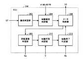
メータ300は、図2に示すように、予め定められた形状のマークを表示するための第1表示部302と、燃料の残量を表示するための第2表示部304と、車両1の速度を表示するための第3表示部306と、燃費を表示するための第4表示部308と、その他の車両1の情報を表示するための第5表示部310とを含む。本実施の形態において、予め定められた形状のマークは、「READY」マークである。 As shown in FIG. 2, the
第1表示部302は、第1態様および第2態様のうちのいずれか一方の態様で乗員に対して車両の状態を告知する。具体的には、第1表示部302は、「READY」マークを点滅状態とする態様を第1態様として、車両1が走行準備状態であることを乗員に告知する。さらに、第1表示部302は、「READY」マークを常時点灯状態とする態様を第2態様として、車両1が走行可能状態であることを乗員に告知する。 The
なお、車両1が走行可能状態であるとは、たとえば、乗員がアクセルペダルを踏み込むことによって車両1が走行を開始できる状態をいう。車両1が走行準備状態であるとは、車両1において走行可能状態とするための動作が行なわれている状態であり、たとえば、スタートスイッチ150に対してIGオン操作がされたことに応じて車両1のシステムの異常の有無のチェックが行なわれている状態である。車両1が走行準備状態である場合において、エンジン10を始動させるために必要な機器は、作動可能な状態となっている。なお、メータ300の構成としては、図2に示す構成に限定されるものではない。 In addition, the
第1表示部302−第5表示部310の各々は、ECU200からの制御信号S3に基づいて点灯したり、消灯したり、あるいは情報を表示したり、表示していた情報を更新したりする。 Each of the
告知装置320は、たとえば、音発生装置あるいは表示装置である。音発生装置は、たとえば、音声を発生させるものであってもよいし、警告音を発生させるものであってもよい。表示装置は、たとえば、メータ300であってもよいし、メータ300と異なる位置に設けられたLCD(Liquid Crystal Display)であってもよいし、メータ300と異なる位置に設けられたインジケータであってもよい。 The
告知装置320は、たとえば、スタートスイッチ150に設けられ、スタートスイッチ150に対する操作に応じて表示色を変化させるインジケータであってもよい。たとえば、インジケータは、IGオフ時において消灯あるいはACCオンで所定色に点灯し、IGオン時に前述の所定色と異なる色に点灯するように表示色を変化させるものであってもよい。告知装置320は、ECU200からの制御信号S4に基づいて所定の態様で乗員に各種情報を告知する。所定の態様とは、たとえば、インジケータの常時点灯状態、インジケータの点滅状態、インジケータの消灯状態、音声による警告、警告の表示等を含む。 The
第1レゾルバ12は、第1MG20の回転速度Nm1を検出する。第1レゾルバ12は、検出された回転速度Nm1を示す信号をECU200に送信する。第2レゾルバ13は、第2MG30の回転速度Nm2を検出する。第2レゾルバ13は、検出された回転速度Nm2を示す信号をECU200に送信する。 The
車輪速センサ14は、駆動輪80の回転速度Nwを検出する。車輪速センサ14は、検出された回転速度Nwを示す信号をECU200に送信する。ECU200は、受信した回転速度Nwに基づいて車速Vを算出する。なお、ECU200は、回転速度Nwに代えて第2MG30の回転速度Nm2に基づいて車速Vを算出するようにしてもよい。 The wheel speed sensor 14 detects the rotational speed Nw of the
ECU200は、エンジン10を制御するための制御信号S1を生成し、その生成した制御信号S1をエンジン10へ出力する。また、ECU200は、PCU60を制御するための制御信号S2を生成し、その生成した制御信号S2をPCU60へ出力する。
ECU200は、エンジン10およびPCU60等を制御することによって車両1が最も効率よく運行できるようにハイブリッドシステム全体、すなわち、バッテリ70の充放電状態、エンジン10、第1MG20および第2MG30の動作状態を制御する。 The
ECU200は、運転席に設けられたアクセルペダル(図示せず)の踏込み量に対応する要求パワーを算出する。ECU200は、算出された要求パワーに応じて、第1MG20および第2MG30のトルクと、エンジン10の出力とを制御する。
上述したような構成を有する車両1においては、発進時や低速走行時等であってエンジン10の効率が悪い場合には、第2MG30のみによる走行が行なわれる。また、通常走行時には、たとえば動力分割装置40によりエンジン10の動力が2経路の動力に分けられる。一方の動力で駆動輪80が直接的に駆動される。他方の動力で第1MG20を駆動して発電が行なわれる。このとき、ECU200は、発電された電力を用いて第2MG30を駆動させる。このように第2MG30を駆動させることにより駆動輪80の駆動補助が行なわれる。 In the
車両1の減速時には、駆動輪80の回転に従動する第2MG30がジェネレータとして機能して回生制動が行なわれる。回生制動によって回収した電力は、バッテリ70に蓄えられる。なお、ECU200は、蓄電装置の残容量(以下の説明においては、SOC(State of Charge)と記載する)が低下し、充電が特に必要な場合には、エンジン10の出力を増加させて第1MG20による発電量を増加させる。これにより、バッテリ70のSOCが増加させられる。また、ECU200は、低速走行時でも必要に応じてエンジン10からの駆動力を増加させる制御を行なう場合もある。たとえば、上述のようにバッテリ70の充電が必要な場合や、エアコン等の補機が駆動される場合や、エンジン10の冷却水の温度を所定温度まで上げる場合等である。 When the
ECU200は、バッテリ70の充電量および放電量を制御する際に、電池温度TBおよび現在のSOCに基づいて、バッテリ70の充電時に許容される入力電力(以下の説明においては、「充電電力上限値Win」と記載する)およびバッテリ70の放電時に許容される出力電力(以下の説明においては、「放電電力上限値Wout」と記載する)を設定する。たとえば、現在のSOCが低下すると、放電電力上限値Woutは徐々に低く設定される。一方、現在のSOCが高くなると、充電電力上限値Winは徐々に低下するように設定される。 When controlling the amount of charge and the amount of discharge of the
また、バッテリ70として用いられる二次電池は、低温時に内部抵抗が上昇する温度依存性を有する。また、高温時には、さらなる発熱によって温度が過上昇することを防止する必要がある。このため、電池温度TBの低温時および高温時には、放電電力上限値Woutおよび充電電力上限値Winの各々が低下させられることが好ましい。ECU200は、電池温度TBおよび現在SOCに応じて、たとえば、マップ等を用いることによって、充電電力上限値Winおよび放電電力上限値Woutを設定する。 Further, the secondary battery used as the
上述した構成を有する車両1において、走行中に乗員により誤ってIGオフ操作が行なわれて車両1のシステムが停止する場合がある。停止状態のシステムを再起動させる操作が乗員によって行なわれた場合、乗員がシステムの再起動状況を認識できない場合がある。これは、システムを再起動させる操作が受け付けられたか否かが不明であるためである。 In the
そこで、本実施の形態においては、ECU200が車両1の走行中にスタートスイッチ150に停止指示を受けた後に起動指示を受けた場合には、第1態様で起動指示を受け付けたことをメータ300あるいは告知装置320を用いて乗員に告知する点に特徴を有する。 Therefore, in the present embodiment, when
図3に、本実施の形態に係る車両1に搭載されたECU200の機能ブロック図を示す。ECU200は、要求判定部202と、始動要否判定部204と、メータ制御部206と、回転速度判定部208と、始動可否判定部210と、始動完了判定部212とを含む。 FIG. 3 shows a functional block diagram of
要求判定部202は、車両1の走行中に車両1のシステムの再起動の要求を受けたか否かを判定する。具体的には、要求判定部202は、スタートスイッチ150からのST信号に基づいて車両1の走行中にIGオフ操作された後にIGオン操作がされたか否かを判定する。なお、要求判定部202は、たとえば、車両1の走行中に車両1のシステムの再起動の要求を受けた場合に、再起動要求判定フラグをオンするようにしてもよい。 The
始動要否判定部204は、要求判定部202によって車両1のシステムの再起動の要求を受けたと判定された場合に、エンジン10の始動が必要であるか否かを判定する。 The start
始動要否判定部204は、たとえば、要求パワーあるいはバッテリ70のSOC等によってエンジン10の始動が必要であるか否かを判定する。要求パワーは、上述のアクセルペダルの踏み込み量に加えて、車速V等に基づいて算出される。要求パワーは、たとえば、車速Vとアクセルペダルの踏み込み量と要求パワーとの関係を示すマップから算出されてもよい。 The start
始動要否判定部204は、算出された要求パワーを第2MG30の出力で満足できない場合には、エンジン10の始動が必要であると判定する。あるいは、始動要否判定部204は、バッテリ70のSOCがエンジン10の始動の要否を決めるためのしきい値を下回る場合に、第1MG20を用いた発電を行なうためにエンジン10の始動が必要であると判定する。 The start
なお、始動要否判定部204は、たとえば、再起動要求判定フラグがオン状態である場合に、エンジン10の始動が必要であるか否かを判定し、エンジン10の始動が必要であると判定された場合に、始動要否判定フラグをオンするようにしてもよい。 The start
メータ制御部206は、始動要否判定部204の判定結果に基づいて起動指示を受け付けたことを乗員に告知するために第1表示部302の「READY」マークに対する点灯制御を実行する。メータ制御部206は、始動要否判定部204の判定結果に基づいて制御信号S3を生成して、メータ300に送信する。 The
メータ制御部206は、始動要否判定部204によってエンジン10の始動が必要でないと判定された場合には、「READY」マークが常時点灯状態になるようにメータ300を制御する。 When the start
メータ制御部206は、始動要否判定部204によってエンジン10の始動が必要であると判定された場合には、「READY」マークが点滅状態になるようにメータ300を制御する。 When the start
メータ制御部206は、後述する始動完了判定部212によってエンジン10の始動が完了したと判定された場合に、「READY」マークを点滅状態から常時点灯状態に移行させる。メータ制御部206は、たとえば、後述する始動完了判定フラグがオフ状態からオン状態となる場合に、「READY」マークを点滅状態から常時点灯状態に移行させてもよい。 The
なお、メータ制御部206は、たとえば、始動要否判定フラグがオフ状態である場合に、「READY」マークが常時点灯状態となり、始動要否判定フラグがオン状態である場合に、「READY」マークが点滅状態となるようにメータ300を制御してもよい。 For example, the
回転速度判定部208は、エンジン10の回転速度Neが所定回転速度Ne(0)以下であるか否かを判定する。所定回転速度Ne(0)以下とは、第1MG20を用いてクランキングができないエンジン10の回転速度領域内であることをいう。 The rotational
高速走行中に何らかの要因によりエンジン10が停止した場合には、直ちにエンジンを再始動できない場合がある。例えば、図4の共線図に記載された実線に示すように、車両1が高速走行している場合が想定される。 If the
なお、図4に示す共線図の三本の縦軸のうちの左側の縦軸がサンギヤ50の回転速度、すなわち、第1MG20の回転速度Nm1を示す。また、図4に示す共線図の中央の縦軸がキャリア54の回転速度、すなわち、エンジン回転速度Neを示す。また、図4に示す共線図の右側の縦軸がリングギヤ56の回転速度、すなわち、第2MG30の回転速度Nm2を示す。なお、図4の共線図の各縦軸の矢印の方向が正回転方向を示し、矢印の方向と逆方向が負回転方向を示す。 Note that the left vertical axis of the three vertical axes in the alignment chart shown in FIG. 4 indicates the rotational speed of the
車両1の走行時においては、第1MG20の回転速度Nm1と、エンジン回転速度Neと、第2MG30の回転速度Nm2とは、図4の共線図上で1本の直線で結ばれる関係を維持するように各要素の回転速度Nm1,Ne,Nm2が変化する。 When the
図4の実線に示すように、第1MG20の回転速度Nm1がNm1(0)であって、エンジン回転速度NeがNe(1)であって、かつ、第2MG30の回転速度Nm2がNm2(0)であるとする。 As shown by the solid line in FIG. 4, the rotation speed Nm1 of the
車両1の高速走行中にIGオフ操作がされた場合に、エンジン10の回転が停止した場合には、車両1は、図2の破線に示す状態となる。このとき、第1MG20を用いてエンジン10を始動させる場合が想定される。この場合、第1MG20の回転速度Nm1をNm1(1)からNm1(0)に引き上げることによって、エンジン回転速度Neを初爆可能な最低エンジン回転速度よりも上昇させる必要がある。 When the IG OFF operation is performed while the
そのため、第1MG20の回転方向(負回転方向)と反対の正回転方向のトルクを生じさせる必要がある。しかしながら、第1MG20の回転速度をNm1(1)からNm1(0)まで上昇させる過程において、第1MG20は発電する。そのため、バッテリ70のSOCが通常のSOC範囲よりも高いことによって充電が制限される場合、すなわち、SOCが通常のSOC範囲内である場合よりも充電電力上限値Winが低下している場合には、第1MG20において発電を行なうことができない場合がある。その結果、エンジン10を直ちに再始動することができない場合がある。 Therefore, it is necessary to generate a torque in the positive rotation direction opposite to the rotation direction (negative rotation direction) of the
そのため、エンジン回転速度Neが所定回転速度Ne(0)以下であるか否かの判定は、第1MG20を用いてエンジン10を直ちに始動できるか否かの判定を意味する。エンジン回転速度Neが所定回転速度Ne(0)以下であるとは、第1MG20を用いてエンジン10を直ちに始動できないことを意味する。所定回転速度Ne(0)は、第1MG20を用いてエンジン10を直ちに始動できるか否かを判定するためのエンジン回転速度Neのしきい値である。 Therefore, the determination of whether or not the engine rotational speed Ne is equal to or lower than the predetermined rotational speed Ne (0) means the determination of whether or not the
なお、回転速度判定部208は、たとえば、始動要否判定フラグがオン状態である場合に、エンジン回転速度Neが所定回転速度Ne(0)以下であるか否かを判定し、エンジン回転速度Neが所定回転速度Ne(0)以下である場合、回転速度判定フラグをオンするようにしてもよい。 Note that the rotational
始動可否判定部210は、エンジン10の始動が可能であるか否かを判定する。具体的には、始動可否判定部210は、車速Vが第1MG20を用いてエンジン10を始動できる速度領域内であるか否か(すなわち、車速Vがしきい値V(0)以下であるか否か)を判定する。始動可否判定部210は、車速Vが第1MG20を用いてエンジン10を始動できる速度領域内である場合に、エンジン10の始動が可能であると判定する。始動可否判定部210は、たとえば、エンジン10の始動が可能である場合に始動可能判定フラグをオンするようにしてもよい。 The
始動完了判定部212は、エンジン10の始動が完了したか否かを判定する。具体的には、始動完了判定部212は、エンジン回転速度Neがエンジン10が始動していることを示す所定回転速度Ne(2)よりも高い場合に、エンジン10の始動が完了したと判定する。なお、始動完了判定部212は、たとえば、エンジン10の始動が完了した場合には、完了判定フラグをオンするようにしてもよい。エンジン10が始動していることを示す所定回転速度Ne(2)とは、たとえば、エンジン10が完爆可能な(自立運転可能な)回転速度である。 The start
本実施の形態において、要求判定部202と、始動要否判定部204と、メータ制御部206と、回転速度判定部208と、始動可否判定部210と、始動完了判定部212とは、いずれもECU200のCPUがメモリに記憶されたプログラムを実行することにより実現される、ソフトウェアとして機能するものとして説明するが、ハードウェアにより実現されるようにしてもよい。なお、このようなプログラムは記憶媒体に記録されて車両に搭載される。 In the present embodiment, the
図5を参照して、本実施の形態に係る車両1に搭載されたECU200で実行されるプログラムの制御構造について説明される。 With reference to FIG. 5, a control structure of a program executed by
ステップ(以下、ステップをSと記載する)100にて、ECU200は、車両1の走行中にシステムの再起動要求があるか否かを判定する。車両1の走行中に車両1のシステムの再起動要求がある場合(S100にてYES)、処理はS102に移される。もしそうでない場合(S100にてNO)、処理はS100に戻される。 In step (hereinafter, step is described as S) 100,
S102にて、ECU200は、エンジン10の始動が必要であるか否かを判定する。エンジン10の始動が必要であるか否かを判定する方法については、上述したとおりであるため、その詳細な説明は繰返されない。エンジン10の始動が必要である場合(S102にてYES)、処理はS104に移される。もしそうでない場合(S102にてNO)、処理はS116に移される。 In S102,
S104にて、ECU200は、第1表示部302の「READY」マークが点滅状態になるようにメータ300を制御する。S106にて、ECU200は、エンジン回転速度Neが所定回転速度Ne(0)以下であるか否かを判定する。エンジン回転速度Neが所定回転速度Ne(0)以下である場合(S106にてYES)、処理はS108に移される。もしそうでない場合(S106にてNO)、処理はS110に移される。 In S104,
S108にて、ECU200は、エンジン10の始動が可能であるか否かを判定する。具体的には、ECU200は、車速Vが所定車速V(0)以下である場合にエンジン10の始動が可能であると判定する。エンジン10の始動が可能である場合(S108にてYES)、処理はS110に移される。もしそうでない場合(S108にてNO)、処理はS108に戻される。 In S108,
S110にて、ECU200は、エンジン10を始動させる。具体的には、ECU200は、第1MG20を用いてエンジン10を初爆可能な回転速度まで上昇させるとともに、燃料噴射制御および点火制御を実行する。 In S110,
S112にて、ECU200は、エンジン10の始動が完了したか否かを判定する。エンジン10の始動が完了したと判定された場合(S112にてYES)、処理はS114に移される。もしそうでない場合(S112にてNO)、処理はS112に戻される。 In S112,
S114にて、ECU200は、「READY」マークを点滅状態から常時点灯状態に移行するようにメータ300を制御する。S116にて、ECU200は、「READY」マークが常時点灯状態になるようにメータ300を制御する。 In S114,
以上のような構造およびフローチャートに基づく本実施の形態に係る車両に搭載されたECUの動作について図6を参照して説明される。 The operation of the ECU mounted on the vehicle according to the present embodiment based on the above-described structure and flowchart will be described with reference to FIG.
図6に示すように、たとえば、システムが起動した状態(IGオン状態)で車両1が走行している場合が想定される。このとき、第1表示部302の「READY」マークは常時点灯状態となる。なお、車速Vは、V(0)よりも高い状態であって、かつ、エンジン回転速度Neは、Ne(2)よりも高い場合が想定される。 As shown in FIG. 6, for example, it is assumed that the
時間T(0)にて、乗員によってスタートスイッチ150に対してIGオフ操作が行なわれる場合には、「READY」マークは消灯し、エンジン10に対してフューエルカット制御が実行される。そのため、車速Vおよびエンジン回転速度Neは、時間の経過とともに低下していく。 When an IG off operation is performed on
時間T(1)にて、乗員によってスタートスイッチ150に対してIGオン操作が行なわれる場合には(S100にてYES)、エンジン10の始動が必要であると判定されると(S102にてYES)、「READY」マークが点滅状態となる(S104)。このとき、乗員は、スタートスイッチ150に対するIGオン操作が受け付けられたことを認識できる。 If it is determined at time T (1) that an IG-on operation is performed on
時間T(1)において、エンジン回転速度NeがNe(0)以下になるまで低下していても(S106にてYES)、車速VがV(0)よりも高い状態である場合には、エンジン10の始動は行なわれない(S108にてNO)。 At time T (1), even if the engine speed Ne has decreased to Ne (0) or less (YES in S106), if the vehicle speed V is higher than V (0), the
時間T(2)にて、車速VがV(0)よりも低下した場合には、エンジン10の始動が可能であると判定されるため(S108にてYES)、エンジン10の始動が行なわれる(S110)。 If vehicle speed V falls below V (0) at time T (2), it is determined that
時間T(3)にて、エンジン回転速度NeがNe(1)以上となることによって、エンジン10の始動が完了した場合(S112にてYES)、第1表示部302の「READY」マークが点滅状態から常時点灯状態に移行する(S114)。 When engine rotation speed Ne is equal to or higher than Ne (1) at time T (3) and
なお、エンジン10の始動が必要であると判定され(S102にてYES)、エンジン回転速度NeがNe(0)よりも高い場合には(S106にてNO)、直ちにエンジン10の始動が行なわれる(S110)。
また、エンジン10の始動が必要でないと判定される場合には(S102にてNO)、第1表示部302の「READY」マークが常時点灯状態となり(S116)、車両1は、エンジン10を停止させた状態で第2MG30を用いて走行する。If it is determined that
If it is determined that the
以上のようにして、本実施の形態に係る車両によると、走行中に車両1のシステムの停止とともにエンジン10が停止した後に再起動が要求された場合に、直ちにエンジン10がかからない場合でも、第1表示部302の「READY」マークが点滅状態となることによって、車両1のシステムの再起動の要求が受け付けられたことを乗員が認識することができる。したがって、システムの再起動状況を乗員に認識させる車両および車両用制御方法を提供することができる。 As described above, according to the vehicle according to the present embodiment, when the
なお、図1では、駆動輪80を前輪とする車両1を一例として示したが、特にこのような駆動方式に限定されるものではない。たとえば、車両1は、後輪を駆動輪とするものであってもよい。あるいは、車両1は、図1の第2MG30が省略された車両であってもよい。または、車両1は、図1の第2MG30が前輪の駆動軸16に代えて、後輪を駆動するための駆動軸に連結される車両であってもよい。また、駆動軸16と減速機58との間あるいは駆動軸16と第2MG30との間に変速機構が設けられてもよい。 In addition, in FIG. 1, although the
あるいは、車両1は、第2MG30を省略し、第1MG20の回転軸をエンジン10の出力軸に直結させ、動力分割装置40に代えて、クラッチを有する変速機を含む構成とされてもよい。 Alternatively,
また、図1においてECU200は、1個のECUであるとして説明したが、2個以上のECUが用いられてもよい。たとえば、図1のECU200の動作を、エンジン10を制御するためのエンジンECUと、PCU60を制御するためのハイブリッドECUとに分担させてもよい。 In FIG. 1, the
さらに、図3のメータ制御部206は、第1表示部302に代えて告知装置320を用いて起動指示を受け付けたことを乗員に告知するようにしてもよい。メータ制御部206は、たとえば、告知装置320が音発生装置である場合には警告音あるいは音声を発生させて起動指示を受け付けたことを乗員に告知してもよい。 Further, the
メータ制御部206は、告知装置320がインジケータ等の表示装置である場合にはインジケータの点灯色を通常(車両1の停車中に起動指示をした場合)の色と異なる所定の色に変化させて起動指示を受け付けたことを乗員に告知してもよい。メータ制御部206は、表示装置の輝度を連続的あるいは段階的に増減させて起動指示を受け付けたことを乗員に告知してもよい。メータ制御部206は、LCDに起動指示を受け付けたことを表示して乗員にその旨を告知してもよい。 When the
この場合、メータ制御部206は、始動要否判定部204の判定結果に基づいて制御信号S4を生成して、告知装置320に送信してもよい。あるいは、メータ制御部206は、走行中に車両1のシステムの起動指示を受け付けたことをメータ300および告知装置320の各々を用いて乗員に告知するようにしてもよい。 In this case, the
さらに、本実施の形態において、走行中に車両1のシステムの起動指示を受けた場合であって、かつ、エンジン10の始動が必要である場合には、エンジン10の始動が完了するまで第1表示部302の「READY」マークを点滅状態とするとして説明したが、たとえば、システムの起動状況にあわせて点滅速度を変化させるようにしてもよい。 Further, in the present embodiment, when the start instruction of the system of the
たとえば、エンジン10の始動が必要であると判定されてからエンジン10の始動が可能であると判定されるまでの間における第1の点滅速度と、エンジン10の始動が可能であると判定されてからエンジン10の始動が完了するまでの間における第2の点滅速度とを異なるようにしてもよい。たとえば、第1の点滅速度を第2の点滅速度よりも速くしたり遅くしたりすることによって、乗員は、システムの起動処理が進行していることを認識することができる。 For example, the first blinking speed from when it is determined that the
また、図3の回転速度判定部208は、エンジン回転速度Neが所定回転速度Ne(0)以下であるか否かによってエンジン10の始動が可能であるか否かを判定するとして説明したが、たとえば、現在の車速においてエンジン10を始動させる場合に発生する発電電力の予測値が、バッテリ70において受け入れ可能な充電電力の範囲内であるか否かによってエンジン10の始動が可能であるか否かを判定してもよい。回転速度判定部208は、たとえば、現在の車速においてエンジン10を始動させる場合に発生する発電電力の予測値が、バッテリ70において受け入れ可能な充電電力の範囲内である場合にエンジン10の始動が可能であると判定する。 3 has been described as determining whether or not the
また、本実施の形態において、ECU200は、走行中に車両1のシステムの再起動が要求された場合には、システムのチェックを行なわずに、エンジン10の始動の必要の有無に応じて「READY」マークを常時点灯状態または点滅状態とすると説明したが、特にこのような動作に限定されない。たとえば、ECU200は、走行中に車両1のシステムの再起動が要求された場合には、「READY]マークを点滅状態とするとともに、車両1のシステムのチェックを行なった後に、エンジン10の始動の必要の有無に応じて「READY」マークを常時点灯状態または点滅状態の継続を行なってもよい。 Further, in the present embodiment, when a restart of the system of the
今回開示された実施の形態はすべての点で例示であって制限的なものではないと考えられるべきである。本発明の範囲は上記した説明ではなくて請求の範囲によって示され、請求の範囲と均等の意味および範囲内でのすべての変更が含まれることが意図される。 The embodiment disclosed this time should be considered as illustrative in all points and not restrictive. The scope of the present invention is defined by the terms of the claims, rather than the description above, and is intended to include any modifications within the scope and meaning equivalent to the terms of the claims.
1 車両、10 エンジン、11 エンジン回転速度センサ、12,13 レゾルバ、14 車輪速センサ、16 駆動軸、20,30 MG、40 動力分割装置、50 サンギヤ、52 ピニオンギヤ、54 キャリア、56 リングギヤ、58 減速機、60 PCU、70 バッテリ、80 駆動輪、102 気筒、104 燃料噴射装置、106 点火装置、150 スタートスイッチ、156 電池温度センサ、158 電流センサ、160 電圧センサ、200 ECU、、202 要求判定部、204 要否判定部、206 メータ制御部、208 回転速度判定部、210 始動可否判定部、212 始動完了判定部、300 メータ、302,304,306,308,310 表示部、320 告知装置。 1 vehicle, 10 engine, 11 engine rotation speed sensor, 12, 13 resolver, 14 wheel speed sensor, 16 drive shaft, 20, 30 MG, 40 power split device, 50 sun gear, 52 pinion gear, 54 carrier, 56 ring gear, 58 deceleration Machine, 60 PCU, 70 battery, 80 driving wheel, 102 cylinder, 104 fuel injection device, 106 ignition device, 150 start switch, 156 battery temperature sensor, 158 current sensor, 160 voltage sensor, 200 ECU, 202 request determination unit, 204 Necessity determination unit, 206 Meter control unit, 208 Rotational speed determination unit, 210 Start availability determination unit, 212 Start completion determination unit, 300 Meter, 302, 304, 306, 308, 310 Display unit, 320 Notification device.
要求判定部202は、車両1の走行中に車両1のシステムの再起動の要求を受けたか否かを判定する。具体的には、要求判定部202は、スタートスイッチ150からの信号STに基づいて車両1の走行中にIGオフ操作された後にIGオン操作がされたか否かを判定する。なお、要求判定部202は、たとえば、車両1の走行中に車両1のシステムの再起動の要求を受けた場合に、再起動要求判定フラグをオンするようにしてもよい。The
1 車両、10 エンジン、11 エンジン回転速度センサ、12,13 レゾルバ、14 車輪速センサ、16 駆動軸、20,30 MG、40 動力分割装置、50 サンギヤ、52 ピニオンギヤ、54 キャリア、56 リングギヤ、58 減速機、60 PCU、70 バッテリ、80 駆動輪、102 気筒、104 燃料噴射装置、106 点火装置、150 スタートスイッチ、156 電池温度センサ、158 電流センサ、160 電圧センサ、200 ECU、、202 要求判定部、204始動要否判定部、206 メータ制御部、208 回転速度判定部、210 始動可否判定部、212 始動完了判定部、300 メータ、302,304,306,308,310 表示部、320 告知装置。1 vehicle, 10 engine, 11 engine rotation speed sensor, 12, 13 resolver, 14 wheel speed sensor, 16 drive shaft, 20, 30 MG, 40 power split device, 50 sun gear, 52 pinion gear, 54 carrier, 56 ring gear, 58 deceleration Machine, 60 PCU, 70 battery, 80 driving wheel, 102 cylinder, 104 fuel injection device, 106 ignition device, 150 start switch, 156 battery temperature sensor, 158 current sensor, 160 voltage sensor, 200 ECU, 202 request determination unit, 204start necessity determination unit, 206 meter control unit, 208 rotational speed determination unit, 210 start possibility determination unit, 212 start completion determination unit, 300 meter, 302, 304, 306, 308, 310 display unit, 320 notification device.
Claims (9)
Translated fromJapanese前記車両(1)の前記システムの停止指示および起動指示を前記乗員から受けるための入力部(150)と、
前記車両(1)の走行中に前記停止指示を前記入力部(150)に受けた後に前記起動指示を前記入力部(150)に受けた場合には、第1態様で前記起動指示を受け付けたことを前記告知部(300、320)を用いて前記乗員に告知するための制御部(200)とを含む、車両。A notification unit (300, 302) for notifying the occupant of the activation state of the system of the vehicle (1);
An input unit (150) for receiving an instruction to stop and start the system of the vehicle (1) from the occupant;
When the start instruction is received by the input unit (150) after the stop instruction is received by the input unit (150) while the vehicle (1) is traveling, the start instruction is received in the first mode. And a control unit (200) for notifying the passenger using the notification unit (300, 320).
前記第1態様は、前記内燃機関(10)を始動させるために必要な機器が作動可能な状態であることを前記乗員に告知するための態様である、請求項1に記載の車両。The vehicle (1) further includes an internal combustion engine (10),
The vehicle according to claim 1, wherein the first mode is a mode for notifying the occupant that a device necessary for starting the internal combustion engine (10) is operable.
前記制御部(200)は、前記走行中に前記停止指示を前記入力部(150)に受けた後に、前記起動指示を前記入力部(150)に受けた場合であって、かつ、前記内燃機関(10)の始動が要求される場合には、前記内燃機関(10)が始動するまで前記第1態様で前記起動指示を受け付けたことを前記告知部(300、320)を用いて前記乗員に告知する、請求項2に記載の車両。The first aspect is an aspect for notifying the occupant that the vehicle (1) is in a traveling preparation state,
The control unit (200) receives the start instruction from the input unit (150) after receiving the stop instruction from the input unit (150) during the traveling, and the internal combustion engine When the start of (10) is required, the notification section (300, 320) is used to notify the occupant that the start instruction has been received in the first mode until the internal combustion engine (10) is started. The vehicle according to claim 2 which announces.
前記制御部(200)は、前記走行中に前記停止指示を前記入力部(150)に受けた後に、前記起動指示を前記入力部(150)に受けた場合であって、かつ、前記内燃機関(10)を停止させた状態で前記駆動用回転電機(30)によって前記車両(1)が走行する場合には、前記第1態様と異なる第2態様で前記告知部(300、320)を用いて前記乗員に告知する、請求項1に記載の車両。The vehicle (1) further includes a drive rotating electrical machine (30) and an internal combustion engine (10),
The control unit (200) receives the start instruction from the input unit (150) after receiving the stop instruction from the input unit (150) during the traveling, and the internal combustion engine When the vehicle (1) travels by the driving rotating electrical machine (30) with the (10) stopped, the notification unit (300, 320) is used in a second mode different from the first mode. The vehicle according to claim 1, wherein the vehicle is notified to the occupant.
前記第2態様は、前記マークを常時点灯させる態様である、請求項4に記載の車両。The first mode is a mode of blinking a mark having a predetermined shape,
The vehicle according to claim 4, wherein the second aspect is an aspect in which the mark is always lit.
前記第2態様は、音によって前記車両(1)が走行可能状態であることを前記乗員に認識させる態様である、請求項4に記載の車両。The first aspect is an aspect in which the occupant recognizes that the activation instruction is received by sound,
The vehicle according to claim 4, wherein the second mode is a mode in which the occupant recognizes that the vehicle (1) is in a travelable state by sound.
前記乗員からの前記起動指示を前記入力部(150)に受けたことに応じて、前記起動指示を受け付けたことを前記第1態様で前記乗員に表示するための第1表示部(300)と、
前記第1表示部(300)とは異なる位置に設けられ、前記車両(1)が走行可能状態であることを前記第2態様で前記乗員に表示するための第2表示部(320)とを含む、請求項4に記載の車両。The notification unit (300, 320)
A first display unit (300) for displaying to the occupant in the first mode that the activation instruction has been received in response to receiving the activation instruction from the occupant at the input unit (150); ,
A second display unit (320) provided at a position different from the first display unit (300) for displaying to the occupant in the second mode that the vehicle (1) is in a travelable state; The vehicle according to claim 4, comprising:
駆動輪(80)を回転させるための駆動軸(16)と、
内燃機関(10)と、
第1回転電機(20)と、
前記駆動軸(16)、前記内燃機関(10)の出力軸および前記第1回転電機(20)の回転軸の三要素の各々を機械的に連結し、前記三要素のうちのいずれか一つを反力要素とすることによって、他の2つの要素間での動力伝達が可能な動力伝達装置(40)とをさらに含む、請求項1に記載の車両。The vehicle (1)
A drive shaft (16) for rotating the drive wheel (80);
An internal combustion engine (10);
A first rotating electrical machine (20);
Each of the three elements of the drive shaft (16), the output shaft of the internal combustion engine (10), and the rotation shaft of the first rotating electrical machine (20) is mechanically connected, and any one of the three elements The vehicle according to claim 1, further comprising: a power transmission device (40) capable of transmitting power between the other two elements by using as a reaction force element.
前記車両(1)の前記システムの停止指示および起動指示のうちのいずれか一方の指示を前記乗員から受けたか否かを判定するステップと、
前記車両(1)の走行中に前記停止指示を受けた後に前記起動指示を受けた場合には、第1態様で前記起動指示を受け付けたことを前記告知部(300、320)を用いて前記乗員に告知するステップとを含む、車両用制御方法。A vehicle control method used for the vehicle (1) equipped with a notification unit (300, 320) for notifying an occupant of the activation state of the system of the vehicle (1),
Determining whether one of a stop instruction and a start instruction of the system of the vehicle (1) has been received from the occupant;
When the activation instruction is received after receiving the stop instruction while the vehicle (1) is traveling, the notification unit (300, 320) uses the notification unit (300, 320) to accept that the activation instruction is received in the first mode. A vehicle control method including a step of notifying an occupant.
Applications Claiming Priority (1)
| Application Number | Priority Date | Filing Date | Title |
|---|---|---|---|
| PCT/JP2011/057151WO2012127677A1 (en) | 2011-03-24 | 2011-03-24 | Vehicle and control method for vehicle |
Publications (1)
| Publication Number | Publication Date |
|---|---|
| JPWO2012127677A1true JPWO2012127677A1 (en) | 2014-07-24 |
Family
ID=46878870
Family Applications (1)
| Application Number | Title | Priority Date | Filing Date |
|---|---|---|---|
| JP2013505744APendingJPWO2012127677A1 (en) | 2011-03-24 | 2011-03-24 | Vehicle and vehicle control method |
Country Status (4)
| Country | Link |
|---|---|
| US (1) | US20140002256A1 (en) |
| JP (1) | JPWO2012127677A1 (en) |
| CN (1) | CN103442926A (en) |
| WO (1) | WO2012127677A1 (en) |
Families Citing this family (9)
| Publication number | Priority date | Publication date | Assignee | Title |
|---|---|---|---|---|
| JP5665231B2 (en)* | 2011-06-28 | 2015-02-04 | 本田技研工業株式会社 | Engine speed display device |
| JP5878430B2 (en)* | 2012-06-08 | 2016-03-08 | トヨタ自動車株式会社 | vehicle |
| WO2015052777A1 (en)* | 2013-10-08 | 2015-04-16 | 日産自動車株式会社 | Device for controlling hybrid vehicle |
| JP6319113B2 (en)* | 2015-01-19 | 2018-05-09 | 株式会社デンソー | Power control device |
| TWI577981B (en)* | 2015-08-27 | 2017-04-11 | 久朝企業有限公司 | Instant detection system of vehicle |
| DE102017207436B4 (en)* | 2017-05-03 | 2019-03-14 | Volkswagen Aktiengesellschaft | Method for operating a lighting of a motor vehicle and motor vehicle for carrying out the method |
| KR102490735B1 (en)* | 2017-10-30 | 2023-01-20 | 현대자동차주식회사 | Display device of a vehicle |
| JP7011568B2 (en) | 2018-11-26 | 2022-01-26 | 本田技研工業株式会社 | In-vehicle device |
| US20250262936A1 (en)* | 2024-02-20 | 2025-08-21 | Ford Global Technologies, Llc | System and method for dimming displays in automotive vehicle |
Citations (3)
| Publication number | Priority date | Publication date | Assignee | Title |
|---|---|---|---|---|
| JP2000080957A (en)* | 1998-09-07 | 2000-03-21 | Daihatsu Motor Co Ltd | Signal judging method of turning angle sensor |
| JP2002332942A (en)* | 2001-05-10 | 2002-11-22 | Toyota Motor Corp | Motor vehicle with engine start signal means |
| JP2007203835A (en)* | 2006-01-31 | 2007-08-16 | Toyota Motor Corp | Control device for hybrid vehicle |
Family Cites Families (23)
| Publication number | Priority date | Publication date | Assignee | Title |
|---|---|---|---|---|
| US6275231B1 (en)* | 1997-08-01 | 2001-08-14 | American Calcar Inc. | Centralized control and management system for automobiles |
| US7253746B2 (en)* | 2004-03-10 | 2007-08-07 | Fujitsu Ten Limited | Vehicle-presence notifying apparatus and vehicle-presence notifying method |
| JP4437468B2 (en)* | 2004-12-06 | 2010-03-24 | 富士通テン株式会社 | Electronic control device for vehicle |
| JP4250149B2 (en)* | 2005-05-10 | 2009-04-08 | 株式会社デンソー | Engine start control system |
| JP4528238B2 (en)* | 2005-09-30 | 2010-08-18 | 株式会社クボタ | Speed control structure of work vehicle |
| JP4155321B2 (en)* | 2006-09-25 | 2008-09-24 | トヨタ自動車株式会社 | Hybrid vehicle display device, hybrid vehicle, and hybrid vehicle display method |
| JP4987551B2 (en)* | 2007-04-19 | 2012-07-25 | 富士通テン株式会社 | Eco-run system, control program, and eco-run status notification device |
| CN101092140A (en)* | 2007-07-12 | 2007-12-26 | 奇瑞汽车有限公司 | Control system of weak mixed dynamical car |
| JP4321648B2 (en)* | 2007-11-08 | 2009-08-26 | トヨタ自動車株式会社 | Hybrid vehicle and control method thereof |
| DE102008039588B4 (en)* | 2007-12-12 | 2016-02-04 | GM Global Technology Operations LLC (n. d. Ges. d. Staates Delaware) | Hybrid machine control system and method for controlling the same |
| US20110017533A1 (en)* | 2009-07-24 | 2011-01-27 | International Truck Intellectual Property Company, Llc | Hybrid traction motor initiated remote start-stop system |
| WO2011125186A1 (en)* | 2010-04-07 | 2011-10-13 | トヨタ自動車株式会社 | Hybrid-vehicle control device and hybrid vehicle provided therewith |
| CN103282255B (en)* | 2010-12-24 | 2016-01-06 | 丰田自动车株式会社 | Vehicle and control method for vehicle |
| CN103282256A (en)* | 2010-12-27 | 2013-09-04 | 丰田自动车株式会社 | Hybrid vehicle and control method therefor |
| JP5598555B2 (en)* | 2011-01-27 | 2014-10-01 | トヨタ自動車株式会社 | Vehicle and vehicle control method |
| US9216726B2 (en)* | 2011-01-27 | 2015-12-22 | Toyota Jidosha Kabushiki Kaisha | Vehicle and control method for vehicle |
| US20130311015A1 (en)* | 2011-02-03 | 2013-11-21 | Toyota Jidosha Kabushiki Kaisha | Vehicle and control method for vehicle |
| EP2672149B1 (en)* | 2011-02-04 | 2017-08-09 | Toyota Jidosha Kabushiki Kaisha | Vehicle control device |
| JP5472527B2 (en)* | 2011-03-10 | 2014-04-16 | トヨタ自動車株式会社 | Vehicle control device |
| WO2013021504A1 (en)* | 2011-08-11 | 2013-02-14 | トヨタ自動車株式会社 | Hybrid vehicle control device |
| US9169786B2 (en)* | 2011-09-02 | 2015-10-27 | Toyota Jidosha Kabushiki Kaisha | Vehicle engine control device |
| JP5871692B2 (en)* | 2012-03-29 | 2016-03-01 | 本田技研工業株式会社 | Vehicle traction control display device |
| JP6024584B2 (en)* | 2013-04-19 | 2016-11-16 | トヨタ自動車株式会社 | Hybrid vehicle |
- 2011
- 2011-03-24JPJP2013505744Apatent/JPWO2012127677A1/enactivePending
- 2011-03-24WOPCT/JP2011/057151patent/WO2012127677A1/ennot_activeCeased
- 2011-03-24CNCN2011800695594Apatent/CN103442926A/enactivePending
- 2011-03-24USUS14/006,632patent/US20140002256A1/ennot_activeAbandoned
Patent Citations (3)
| Publication number | Priority date | Publication date | Assignee | Title |
|---|---|---|---|---|
| JP2000080957A (en)* | 1998-09-07 | 2000-03-21 | Daihatsu Motor Co Ltd | Signal judging method of turning angle sensor |
| JP2002332942A (en)* | 2001-05-10 | 2002-11-22 | Toyota Motor Corp | Motor vehicle with engine start signal means |
| JP2007203835A (en)* | 2006-01-31 | 2007-08-16 | Toyota Motor Corp | Control device for hybrid vehicle |
Also Published As
| Publication number | Publication date |
|---|---|
| WO2012127677A1 (en) | 2012-09-27 |
| US20140002256A1 (en) | 2014-01-02 |
| CN103442926A (en) | 2013-12-11 |
Similar Documents
| Publication | Publication Date | Title |
|---|---|---|
| CN105579311B (en) | The control device and control method of motor vehicle driven by mixed power | |
| JPWO2012127677A1 (en) | Vehicle and vehicle control method | |
| US20140288757A1 (en) | Hybrid vehicle | |
| CN101583526A (en) | Vehicle and its control method | |
| JP5598555B2 (en) | Vehicle and vehicle control method | |
| CN101687507A (en) | Hybrid vehicle and hybrid vehicle control method | |
| JP5825115B2 (en) | Plug-in hybrid vehicle | |
| JP5652479B2 (en) | Vehicle and vehicle control method | |
| JP6947051B2 (en) | Hybrid car | |
| JP2015231796A (en) | Hybrid vehicle | |
| JP2013141858A (en) | Controller for hybrid vehicle | |
| JP5644868B2 (en) | Vehicle and vehicle control method | |
| JP5565256B2 (en) | Hybrid vehicle and information output method | |
| JP5652546B2 (en) | Vehicle and vehicle control method | |
| JP4957298B2 (en) | Hybrid vehicle and control method thereof | |
| JP2015231757A (en) | Hybrid vehicle | |
| JP2012162097A (en) | Vehicle | |
| JP5810580B2 (en) | Vehicle and vehicle control method | |
| JP5700053B2 (en) | Vehicle and vehicle control method | |
| JP7437364B2 (en) | display control device | |
| WO2012105019A1 (en) | Vehicle and method for controlling vehicle | |
| JP7403920B2 (en) | Electric vehicle control device | |
| JP2024008640A (en) | display control device | |
| JP2013132945A (en) | Control device of hybrid vehicle | |
| JP2012236470A (en) | Damping control device of vehicle |
Legal Events
| Date | Code | Title | Description |
|---|---|---|---|
| A131 | Notification of reasons for refusal | Free format text:JAPANESE INTERMEDIATE CODE: A131 Effective date:20140729 | |
| A521 | Request for written amendment filed | Free format text:JAPANESE INTERMEDIATE CODE: A523 Effective date:20140924 | |
| A02 | Decision of refusal | Free format text:JAPANESE INTERMEDIATE CODE: A02 Effective date:20150120 |