JPWO2012101728A1 - Battery module and assembled battery used therefor - Google Patents
Battery module and assembled battery used thereforDownload PDFInfo
- Publication number
- JPWO2012101728A1 JPWO2012101728A1JP2012520610AJP2012520610AJPWO2012101728A1JP WO2012101728 A1JPWO2012101728 A1JP WO2012101728A1JP 2012520610 AJP2012520610 AJP 2012520610AJP 2012520610 AJP2012520610 AJP 2012520610AJP WO2012101728 A1JPWO2012101728 A1JP WO2012101728A1
- Authority
- JP
- Japan
- Prior art keywords
- connection terminal
- battery
- case
- connection
- unit cells
- Prior art date
- Legal status (The legal status is an assumption and is not a legal conclusion. Google has not performed a legal analysis and makes no representation as to the accuracy of the status listed.)
- Pending
Links
Images


Classifications
- H—ELECTRICITY
- H01—ELECTRIC ELEMENTS
- H01M—PROCESSES OR MEANS, e.g. BATTERIES, FOR THE DIRECT CONVERSION OF CHEMICAL ENERGY INTO ELECTRICAL ENERGY
- H01M50/00—Constructional details or processes of manufacture of the non-active parts of electrochemical cells other than fuel cells, e.g. hybrid cells
- H01M50/50—Current conducting connections for cells or batteries
- H01M50/543—Terminals
- H—ELECTRICITY
- H01—ELECTRIC ELEMENTS
- H01M—PROCESSES OR MEANS, e.g. BATTERIES, FOR THE DIRECT CONVERSION OF CHEMICAL ENERGY INTO ELECTRICAL ENERGY
- H01M50/00—Constructional details or processes of manufacture of the non-active parts of electrochemical cells other than fuel cells, e.g. hybrid cells
- H01M50/50—Current conducting connections for cells or batteries
- H01M50/528—Fixed electrical connections, i.e. not intended for disconnection
- H01M50/529—Intercell connections through partitions, e.g. in a battery casing
- H—ELECTRICITY
- H01—ELECTRIC ELEMENTS
- H01M—PROCESSES OR MEANS, e.g. BATTERIES, FOR THE DIRECT CONVERSION OF CHEMICAL ENERGY INTO ELECTRICAL ENERGY
- H01M50/00—Constructional details or processes of manufacture of the non-active parts of electrochemical cells other than fuel cells, e.g. hybrid cells
- H01M50/20—Mountings; Secondary casings or frames; Racks, modules or packs; Suspension devices; Shock absorbers; Transport or carrying devices; Holders
- H01M50/204—Racks, modules or packs for multiple batteries or multiple cells
- H01M50/207—Racks, modules or packs for multiple batteries or multiple cells characterised by their shape
- H01M50/213—Racks, modules or packs for multiple batteries or multiple cells characterised by their shape adapted for cells having curved cross-section, e.g. round or elliptic
- H—ELECTRICITY
- H01—ELECTRIC ELEMENTS
- H01M—PROCESSES OR MEANS, e.g. BATTERIES, FOR THE DIRECT CONVERSION OF CHEMICAL ENERGY INTO ELECTRICAL ENERGY
- H01M50/00—Constructional details or processes of manufacture of the non-active parts of electrochemical cells other than fuel cells, e.g. hybrid cells
- H01M50/20—Mountings; Secondary casings or frames; Racks, modules or packs; Suspension devices; Shock absorbers; Transport or carrying devices; Holders
- H01M50/296—Mountings; Secondary casings or frames; Racks, modules or packs; Suspension devices; Shock absorbers; Transport or carrying devices; Holders characterised by terminals of battery packs
- H—ELECTRICITY
- H01—ELECTRIC ELEMENTS
- H01M—PROCESSES OR MEANS, e.g. BATTERIES, FOR THE DIRECT CONVERSION OF CHEMICAL ENERGY INTO ELECTRICAL ENERGY
- H01M50/00—Constructional details or processes of manufacture of the non-active parts of electrochemical cells other than fuel cells, e.g. hybrid cells
- H01M50/50—Current conducting connections for cells or batteries
- H01M50/531—Electrode connections inside a battery casing
- H—ELECTRICITY
- H01—ELECTRIC ELEMENTS
- H01M—PROCESSES OR MEANS, e.g. BATTERIES, FOR THE DIRECT CONVERSION OF CHEMICAL ENERGY INTO ELECTRICAL ENERGY
- H01M6/00—Primary cells; Manufacture thereof
- H01M6/42—Grouping of primary cells into batteries
- Y—GENERAL TAGGING OF NEW TECHNOLOGICAL DEVELOPMENTS; GENERAL TAGGING OF CROSS-SECTIONAL TECHNOLOGIES SPANNING OVER SEVERAL SECTIONS OF THE IPC; TECHNICAL SUBJECTS COVERED BY FORMER USPC CROSS-REFERENCE ART COLLECTIONS [XRACs] AND DIGESTS
- Y02—TECHNOLOGIES OR APPLICATIONS FOR MITIGATION OR ADAPTATION AGAINST CLIMATE CHANGE
- Y02E—REDUCTION OF GREENHOUSE GAS [GHG] EMISSIONS, RELATED TO ENERGY GENERATION, TRANSMISSION OR DISTRIBUTION
- Y02E60/00—Enabling technologies; Technologies with a potential or indirect contribution to GHG emissions mitigation
- Y02E60/10—Energy storage using batteries
Landscapes
- Chemical & Material Sciences (AREA)
- Chemical Kinetics & Catalysis (AREA)
- Electrochemistry (AREA)
- General Chemical & Material Sciences (AREA)
- Engineering & Computer Science (AREA)
- Manufacturing & Machinery (AREA)
- Battery Mounting, Suspending (AREA)
- Connection Of Batteries Or Terminals (AREA)
Abstract
Translated fromJapaneseDescription
Translated fromJapanese本発明は、複数の電池からなる組電池が複数個積層された構成の電池モジュール、及びそれに用いる組電池に関する。 The present invention relates to a battery module having a configuration in which a plurality of assembled batteries made of a plurality of batteries are stacked, and an assembled battery used therefor.
複数の電池をケースに収容して、所定の電圧及び容量を出力できるようにした電池パックは、種々の機器、車両等の電源として広く使用されている。中でも、汎用的な電池を並列・直列接続して、所定の電圧及び容量を出力する組電池をモジュール化し、この電池モジュールを種々組み合わせることによって、多種多様な用途に対応可能とする技術が採用され始めている。このモジュール化技術は、電池モジュールに収容する電池を高性能化することによって、電池モジュール自身の小型・軽量化が図られるため、電池パックを組み立てる際の作業性が向上するとともに、車両等の限られた空間へ搭載する際の自由度が向上するなど、様々なメリットも有する。 A battery pack in which a plurality of batteries are accommodated in a case so as to output a predetermined voltage and capacity is widely used as a power source for various devices and vehicles. In particular, a technology is adopted that can support a wide variety of applications by connecting general-purpose batteries in parallel and in series, modularizing assembled batteries that output a predetermined voltage and capacity, and combining these battery modules in various ways. I'm starting. This modularization technology improves the workability when assembling the battery pack and improves the performance of the battery stored in the battery module by improving the performance of the battery accommodated in the battery module. There are various advantages, such as an improved degree of freedom when mounted in a designated space.
例えば車両用の電源として、リチウムイオン二次電池を用いた電池モジュールの開発が行われているが、リチウムイオン二次電池に限らず、電池の種類によって最適な高出力および高容量特性を得るため、複数の組電池を直列接続や並列接続を行った電池モジュールを形成することが必要になる。 For example, a battery module using a lithium ion secondary battery has been developed as a power source for vehicles. However, not only a lithium ion secondary battery, but also to obtain optimum high output and high capacity characteristics depending on the type of battery. It is necessary to form a battery module in which a plurality of assembled batteries are connected in series or in parallel.
特許文献1には、複数の電池がケースに収容された組電池の組み立てとして、各ケースの周縁部に貫通孔を設け、各貫通孔にボルトを挿入して、ケース同士を互いに締結して、電池モジュールを構成する方法が記載されている。 In
しかしながら特許文献1に開示された技術は、組電池同士を相互に締結して電池モジュールを構成しているため、組電池の位置決めが難しく、電池モジュールの組立てや分解が煩雑になる。また、組電池同士をボルトで締結するため、活電部(電極端子)が組電池の外部に存在するため、接触による感電に気を配りしながら、電池モジュールの組み立て作業を行わなければならない。 However, since the technique disclosed in
本発明は、組電池同士の組合せによる組立てや分解が容易で、かつ、活電部の接触による感電を防ぐことのできる電池モジュールを提供することを目的とする。 An object of the present invention is to provide a battery module that can be easily assembled and disassembled by a combination of assembled batteries and can prevent an electric shock due to contact of a live part.
本発明に係る電池モジュールは、複数の組電池が積層された電池モジュールであって、組電池は、複数の素電池を、一方の極を揃えて収容する絶縁性のケースと、複数の素電池の一方の極を並列接続する第1の接続板と、複数の素電池の他方の極を並列接続する第2の接続板とを備え、第1の接続板及び第2の接続板は、素電池に対して、互いに反対方向に配設されており、第1の接続板は、第2の接続板と反対方向に延出する第1の接続端子を有し、第2の接続板は、第1の接続端子と同じ方向に延出する第2の接続端子を有し、第1の接続端子は、ケース外に突出しており、第2の接続端子は、ケース内に埋設しており、積層方向に隣接する組電池は、一方の組電池の第1の接続端子と、他方の組電池の第2の接続端子が、互いに嵌合して直列接続しており、一方の組電池の第1の接続端子は、他方の組電池のケース内に埋設している。 The battery module according to the present invention is a battery module in which a plurality of assembled batteries are stacked, and the assembled battery includes an insulating case that accommodates a plurality of unit cells with one electrode aligned, and a plurality of unit cells. A first connection plate for connecting one of the electrodes in parallel, and a second connection plate for connecting the other of the plurality of unit cells in parallel, wherein the first connection plate and the second connection plate include: The first connection plate has first connection terminals extending in the opposite direction to the second connection plate, and the second connection plate is disposed in opposite directions with respect to the battery. A second connection terminal extending in the same direction as the first connection terminal, the first connection terminal protrudes out of the case, and the second connection terminal is embedded in the case; In the assembled battery adjacent in the stacking direction, the first connection terminal of one assembled battery and the second connection terminal of the other assembled battery are fitted together. And connected in series, a first connection terminal of one battery pack is embedded in the other of the battery pack case.
このような構成により、一方の組電池の第1の接続端子と他方の組電池の第2の接続端子とを、ケース内で直列接続させることができるので、組電池同士の組立てが容易になるともに、活電部の接触による感電を防ぐことができる。 With such a configuration, the first connection terminal of one assembled battery and the second connection terminal of the other assembled battery can be connected in series within the case, so that assembly of the assembled batteries is facilitated. In both cases, electric shock due to contact of the live parts can be prevented.
本発明によれば、組電池同士の組合せによる組立てや分解が容易で、かつ、活電部の接触による感電を防ぐことのできる電池モジュールを提供することができる。 ADVANTAGE OF THE INVENTION According to this invention, the battery module which can be easily assembled and disassembled by the combination of assembled batteries, and can prevent the electric shock by the contact of a live part can be provided.
以下、本発明の実施形態を図面に基づいて詳細に説明する。なお、本発明は、以下の実施形態に限定されるものではない。また、本発明の効果を奏する範囲を逸脱しない範囲で、適宜変更は可能である。さらに、他の実施形態との組み合わせも可能である。 Hereinafter, embodiments of the present invention will be described in detail with reference to the drawings. In addition, this invention is not limited to the following embodiment. Moreover, it can change suitably in the range which does not deviate from the range which has the effect of this invention. Furthermore, combinations with other embodiments are possible.
図1は、本発明の一実施形態における組電池に使用する電池(以下、「素電池」という)100の構成を模式的に示した断面図である。 FIG. 1 is a cross-sectional view schematically showing a configuration of a battery (hereinafter referred to as “unit cell”) 100 used for an assembled battery according to an embodiment of the present invention.
本発明における組電池を構成する素電池100は、例えば、図1に示すような、円筒形のリチウムイオン二次電池を採用することができる。 For example, a cylindrical lithium ion secondary battery as shown in FIG. 1 can be adopted as the
このリチウムイオン二次電池は、ノート型パソコン等の携帯用電子機器の電源として使用される汎用電池であってもよい。この場合、高性能の汎用電池を、電池モジュールの素電池として使用することができるため、電池モジュールの高性能化、低コスト化をより容易に図ることができる。また、素電池100は、内部短絡等の発生により電池内の圧力が上昇したとき、ガスを電池外に放出する安全機構を備えている。以下、図1を参照しながら、素電池100の具体的な構成を説明する。 This lithium ion secondary battery may be a general-purpose battery used as a power source for portable electronic devices such as notebook computers. In this case, since a high-performance general-purpose battery can be used as a unit cell of the battery module, it is possible to easily improve the performance and cost of the battery module. In addition, the
図1に示すように、正極1と負極2とがセパレータ3を介して捲回された電極群4が、非水電解液とともに、電池ケース7に収容されている。電極群4の上下には、絶縁板9、10が配され、正極1は、正極リード5を介してフィルタ12に接合され、負極2は、負極リード6を介して負極端子を兼ねる電池ケース7の底部に接合されている。 As shown in FIG. 1, an electrode group 4 in which a
フィルタ12は、インナーキャップ13に接続され、インナーキャップ13の突起部は、金属製の弁体14に接合されている。さらに、弁体14は、正極端子を兼ねる端子板8に接続されている。そして、端子板8、弁体14、インナーキャップ13、及びフィルタ12が一体となって、ガスケット11を介して、電池ケース7の開口部が封口されている。 The
素電池100に内部短絡等が発生して、素電池100内の圧力が上昇すると、弁体14が端子板8に向かって膨れ、インナーキャップ13と弁体14との接合がはずれると、電流経路が遮断される。さらに素電池100内の圧力が上昇すると、弁体14が破断する。これによって、素電池100内に発生したガスは、フィルタ12の貫通孔12a、インナーキャップ13の貫通孔13a、弁体14の裂け目、そして、端子板8の開放部8aを介して、外部へ排出される。 When an internal short circuit or the like occurs in the
なお、素電池100内に発生したガスを外部に排出する安全機構は、図1に示した構造に限定されず、他の構造のものであってもよい。 In addition, the safety mechanism which discharges | emits the gas generated in the
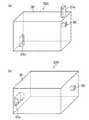
次に、図2(a)、(b)、及び図3(a)、(b)を参照しながら、本発明の一実施形態における組電池200の構成を説明する。ここで、図2(a)は、組電池200の上面図、図2(b)は、図2(a)のB−B断面図である。また、図3(a)は、組電池200の上方から見た斜視図、図3(b)は組電池200の下方から見た斜視図である。 Next, the configuration of the assembled
図2(a)、(b)に示すように、組電池200は、複数の素電池100を、一方の極を揃えて絶縁性のケース30に収容されている。そして、複数の素電池100の正極端子8は、正極接続板(第1の接続板)21によって並列接続されている。また、複数の素電池100の負極端子(電池ケース7の底部)は、負極接続板(第2の接続板)22によって並列接続されている。また、正極接続板21及び負極接続板22は、素電池100に対して、互いに反対方向に配設されている。 As shown in FIGS. 2A and 2B, the assembled
ここで、正極接続板21は、負極接続板22と反対方向(素電池100の負極端子側から正極端子側の方向)に延出する正極接続端子(第1の接続端子)21aを有し、負極接続板22は、正極接続端子21aと同じ方向に延出する負極接続端子(第2の接続端子)を有している。そして、図3(a)、(b)に示すように、正極接続端子21aは、ケース30外に突出しており、負極接続端子22aは、ケース30内に埋設している。 Here, the positive
図2(a)、(b)、及び図3(a)、(b)を参照しながら、本実施形態における組電池200の構成をさらに詳しく説明する。 With reference to FIGS. 2A and 2B and FIGS. 3A and 3B, the configuration of the assembled
図2(a)に示すように、複数の素電池(筒状電池)100が、千鳥配列(図では、5個、4個、5個からなる3列で配列)して、ケース30内に収容されて、組電池200を構成している。ここで、素電池100の正極端子8は同一方向に揃って配列され、複数の素電池100は電気的に並列に接続されている。これにより、複数の組電池200を集合した電池モジュール(さらには、複数の電池モジュールを集合した電池パック)において、万一、組電池200を構成する素電池100の一つが故障しても、電池モジュール(さらには電池パック)の電流供給を確保することができる。 As shown in FIG. 2A, a plurality of unit cells (tubular batteries) 100 are arranged in a staggered arrangement (in the figure, arranged in three rows of five, four, and five) in the
具体的には、図2(b)に示すように、ケース30内で素電池100の上下を挟むように、正極接続板21と負極接続板22とを配置している。正極接続板21は各素電池100の正極端子8と接続している。また、負極接続板22は各素電池100の負極端子(電池ケース7の底部)と接続している。これにより、各素電池100は、正極接続板21及び負極接続板22によって電気的に並列接続されている。 Specifically, as shown in FIG. 2B, the positive
正極接続板21及び負極接続板22は電気的導通性のある金属、例えば、銅(Cu)、ニッケル(Ni)などで構成されている。そして、正極接続板21は凸状(筒状)で、ケース30外に突出した正極接続端子21aを有し、負極接続板22は凹状(中空筒状)で、ケース30内に埋設した負極接続端子22aを有している。 The positive
正極接続板21は、素電池100の一端部(本実施形態では、正極端子8側)に密着して配設され、正極接続板21とケース30の蓋40との間に、排気ダクト50が形成されている。また、素電池100の開放部8aは、正極接続板21に形成された開口部21bを介して、排気ダクト50に連通している。これにより、素電池100の開放部8aから排出される高温ガスは、正極接続板21に形成された開口部21bを介して排気ダクト50に排出される。また、排気ダクト50は、複数の素電池100に対して略密閉状態で区画されているため、排気ダクト50に排出された高温ガスを、周辺の素電池100に曝されることなく、蓋40に設けられた排出口40aから組電池200外に放出させることができる。 The positive
図3(a)、(b)に示すように、組電池200は、ケース30の上部に凸状(筒状)の正極接続端子21aと、ケース30の下部に凹状(中空筒状)の負極接続端子22aとを有している。正極接続端子21aと負極接続端子22aとは、複数の組電池200を積層して電気的接続ができるように、正極接続端子21aの外径と負極接続端子22aの内径は略同一である。 As shown in FIGS. 3A and 3B, the assembled
正極接続端子21aと負極接続端子22aは、図面の左右の位置で反対の位置に配置している。こうすることにより、正極接続端子21a、素電池100、負極接続端子22aの電流の経路が、全ての素電池100においてほぼ同一の距離になる。それゆえ、全ての素電池100の消耗度合を均一にすることができる。 The positive
ケース30は、熱伝導性の樹脂で形成されている。そのため、組電池200は、正極接続端子21aと負極接続端子22a以外は、電気的に絶縁になっており、接触による感電を防止することができる。 The
また、計測用端子60がケース30の側面に埋め込まれていてもよい。計測用端子60は、組電池200の温度や電圧を計測するための端子で、組電池200の正極接続板21若しくは負極接続板22に接続されている。組電池200の温度や電圧は、計測用端子60に測定機器の外部端子を接続して測定することができる。これにより、計測用端子60の活電部もケース30内に隠れた状態となっている。 Further, the
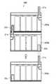
次に、図4を参照ながら、本実施形態における電池モジュール300の構成を説明する。ここで、図4は、本実施形態における電池モジュール300の構成を示した断面図で、組電池200aと組電池200bとは既に組み合わされた状態を、組電池200cは、組み合わされる前の状態を、それぞれ示している。 Next, the configuration of the
図4に示すように、本実施形態における電池モジュール300は、複数の組電池200a〜200cが積層された構成をなす。本実施形態において、積層方向に隣接する組電池は、一方の組電池200aの正極接続端子(第1の接続端子)21aと、他方の組電池200bの負極接続端子(第2の接続端子)22aが、互いに嵌合して直列接続している。これにより、一方の組電池200aの正極接続端子21aは、他方の組電池200bのケース30内に埋設している。なお、組電池200bと組電池200cとの積層も、同様に行われる。 As shown in FIG. 4, the
このような構成により、一方の組電池200aの正極接続端子21aと、他方の組電池200bの負極接続端子22aとを、ケース30内で直列接続させることができるので、組電池同士の組立てが容易になるともに、ケース30外に突出した正極接続端子21a(活電部)の接触による感電を防ぐことができる。これにより、組電池200同士の組合せによる組立てや分解が容易で、かつ、活電部の接触による感電を防ぐことのできる電池モジュール300を実現することができる。 With such a configuration, the positive
ここで、正極接続端子21a及び負極接続端子22aの形状は特に制限されないが、例えば、正極接続端子21aを筒状に、負極接続端子22aを中空筒状にした場合、正極接続端子21aの外周面は、負極接続端子22aの内周面に嵌合して直列接続される。 Here, the shapes of the positive
また、正極接続端子21a及び負極接続端子22aの少なくとも一方の接続端子は、弾性変形して、他方の接続端子に嵌合していることが好ましい。これにより、正極接続端子21a及び負極接続端子22aの接触面積を増大させることができ、接触抵抗を低減できる。 Moreover, it is preferable that at least one of the
また、正極接続端子21a及び負極接続端子22aは、それぞれ、正極接続板21及びと負極接続板22と一体形成されていてもよい。これにより、部品点数を低減でき、組立て工数、及び組立てコストを低減できる。ここで、正極接続板21(または負極接続板22)と正極接続端子21a(または負極接続端子22a)との一体成形は、例えば、深絞り加工を用いて行うことができる。 The positive
また、複数の素電池100の配列の仕方は特に制限されないが、図2(a)に示したように、m個の素電池の配列と、m−1個の素電池の配列とを交互に千鳥配置して、ケース30内に収容することが好ましい。この場合、正極接続端子21a及び負極接続端子22aは、m−1個の素電池の配列における両端部にそれぞれ配置することができる。これにより、組電池200の容積を増大することなく、正極接続端子21a及び負極接続端子22aを配設することができる。 The arrangement of the plurality of
図4を参照しながら、本実施形態における電池モジュール300の構成をさらに詳しく説明する。 With reference to FIG. 4, the configuration of the
図4に示すように、複数の組電池200a〜200cを、正極及び負極の方向(図面の上下方向)は同じ向きに配置して、正極接続端子21a及び負極接続端子22aを交互に反対方向(図面の左右方向)に配置する。このような配置にすることにより、組電池200aの負極接続端子22aと、組電池200bの正極接続端子21aとを組合せでき、組電池200bの負極接続端子22aと、組電池200cの正極接続端子21aとを組合せできる。このように、正極接続端子21aと負極接続端子22aとの組合せを行うことで、組電池200同士を容易に組立てることができる。また、正極接続端子21aと負極接続端子22aとの組合せを解除することで、組電池200同士を容易に分解することができる。 As shown in FIG. 4, the plurality of assembled
また、複数の組電池200を正極接続端子21aと負極接続端子22aで組み合わせることにより、複数の組電池200を直列接続することができる。そして、複数の組電池200を組合せたとき、正極接続端子21aと負極接続端子22aとが絶縁性のケース30の内部で組み合わされているので、組電池200の活電部を電池ケースの内部に収納することができる。これにより、活電部の接触による感電を防ぐことができる。 Moreover, the some assembled
また、組電池200の計測用端子60もケース30の内部に埋め込まれているので、計測用端子60による活電部の接触による感電も防ぐことができる。そして、計測用端子60は電池モジュール300の側面に配置されているので、容易に測定機器の外部端子を接続することができる。 Moreover, since the
複数の組電池200を組合させた電池モジュール300において、組電池200aの正極接続端子21aと組電池200cの負極接続端子22aのみが、活電部として露出されている。これら組電池200aの正極接続端子21aと組電池200cの負極接続端子22aを、電池モジュール300を接続する機器の正極及び負極の端子に各々接続することで、機器に電力を供給することができる。 In the
正極接続端子21aと負極接続端子22aは、ファストン端子、或いは、スロットインコネクターと同様の機能を示す構成としている。これにより、組電池200同士を電気的に接続すると共に、構造的にも容易に組合せすることが可能となる。 The positive
かかる構成によれば、正極接続板21の正極接続端子21aと、負極接続板22の負極接続端子22aを組合せ構造とし、正極接続端子21aと負極接続端子22aのみを樹脂製のケース30から露出させることで、組電池200同士を簡単に組合せすることができると共に、活電部を組電池200の外部に存在させないので、活電部の接触による感電を防ぐことができる。 According to this configuration, the positive
以上、本発明を好適な実施形態により説明してきたが、こうした記述は限定事項ではなく、勿論、種々の改変が可能である。例えば、上記実施形態では、図2(b)に示したように、正極接続端子(第1の接続端子)21aを、ケース30外に突出させたが、負極接続端子(第2の接続端子)22aと同様に、ケース30内に埋設させてもよい。この場合、図5に示すように、積層方向に隣接する組電池200a、200bにおいて、正極接続端子21a及び負極接続端子22aは、共に中空筒状をなしており、正極接続端子21a及び負極接続端子22aの内周面と当接する外周面を有する筒状の連結部材23を介して、互いに嵌合して直列接続している。このとき、正極接続端子21aの内径と、負極接続端子22aの内径とは、略同一である。 As mentioned above, although this invention was demonstrated by suitable embodiment, such description is not a limitation matter and of course various modifications are possible. For example, in the above embodiment, as shown in FIG. 2B, the positive electrode connection terminal (first connection terminal) 21a protrudes outside the
また、上記実施形態では、図2(a)に示したように、正極接続端子21a及び負極接続端子22aを、半円柱形状としたが、例えば、図6に示すように、円柱形状としてもよい。なお、正極接続端子21aは、中空筒状であっても、中実筒状であってもよい。 Moreover, in the said embodiment, as shown to Fig.2 (a), although the positive electrode connecting terminal 21a and the negative electrode connecting terminal 22a were made into the semicylindrical shape, it is good also as a cylindrical shape as shown, for example in FIG. . The positive
また、上記実施形態では、ケース30を熱伝導性の樹脂で構成したが、表面を樹脂層で覆った金属板としてもよい。これにより、ケースの強度を向上させると共に、熱伝導を向上させることができる。 Moreover, in the said embodiment, although
また、上記実施形態では、図2(a)に示したように、正極接続端子21a及び負極接続端子22aを、真ん中の素電池100の列(4個の素電池100の列)の両端に1個ずつ設けたが、列中央部の素電池100を取り除いて、組電池200の中央部に、正極接続端子21a及び負極接続端子22aを設けてもよい。これにより、排気ダクト50を介して素電池100からの排気ガスを排気する排出口40aや、計測用端子60を同一方向に揃えることができる。なお、この場合、正極接続端子21a、素電池100、負極接続端子22aの電流の経路が、中央と周辺で少し異なるが、その差は、組電池200の外形の1/2の長さ以下に止まる。 Moreover, in the said embodiment, as shown to Fig.2 (a), the positive electrode connecting terminal 21a and the negative electrode connecting terminal 22a are set to 1 in the both ends of the row | line | column of the middle cell 100 (4
また、正極接続端子21a及び負極接続端子22aを、真ん中の素電池100の列の両端に1個ずつ設けたが、真ん中の素電池100の列の両端に2個ずつ設けてもよい。これにより、組電池200の組合せ強度が向上できるとともに、電流経路を2倍にすることができる、その結果、正極接続板21や負極接続板22での発熱を防ぐことができる。 Further, one positive
本発明における電池モジュールは、自動車、電動バイク又は電動遊具等の駆動用電源として有用である。 The battery module in the present invention is useful as a driving power source for automobiles, electric motorcycles, electric playground equipment and the like.
1 正極
2 負極
3 セパレータ
4 電極群
5 正極リード
6 負極リード
7 電池ケース
8 正極端子(端子板)
8a 開放部
9、10 絶縁板
11 ガスケット
12 フィルタ
12a、13a 貫通孔
13 インナーキャップ
14 弁体
21 正極接続板 (第1の接続板)
21a 正極接続端子 (第1の接続端子)
21b 開口部
22 負極接続板 (第2の接続板)
22a 負極接続端子(第2の接続端子)
23 連結部材
30 ケース
40 蓋
40a 排出口
50 排気ダクト
60 計測用端子
100 素電池
200 組電池
300 電池モジュール1 Positive electrode
2 Negative electrode
3 Separator
4 Electrode group
5 Positive lead
6 Negative lead
7 Battery case
8 Positive terminal (terminal plate)
8a Open part
9, 10 Insulation plate
11 Gasket
12 Filter
12a, 13a Through hole
13 Inner cap
14 Disc
21 Positive connection plate (first connection plate)
21a Positive connection terminal (first connection terminal)
21b opening
22 Negative connection plate (second connection plate)
22a Negative connection terminal (second connection terminal)
23 Connecting member
30 cases
40 lids
40a outlet
50 Exhaust duct
60 Measuring terminal
100 unit cells
200 batteries
300 Battery module
Claims (11)
Translated fromJapanese前記組電池は、
複数の素電池を、一方の極を揃えて収容する絶縁性のケースと、
前記複数の素電池の一方の極を並列接続する第1の接続板と、
前記複数の素電池の他方の極を並列接続する第2の接続板と、
を備え、
前記第1の接続板及び前記第2の接続板は、前記素電池に対して、互いに反対方向に配設されており、
前記第1の接続板は、前記第2の接続板と反対方向に延出する第1の接続端子を有し、
前記第2の接続板は、前記第1の接続端子と同じ方向に延出する第2の接続端子を有し、
前記第1の接続端子は、前記ケース外に突出しており、
前記第2の接続端子は、前記ケース内に埋設しており、
積層方向に隣接する前記組電池は、一方の組電池の第1の接続端子と、他方の組電池の第2の接続端子が、互いに嵌合して直列接続しており、
前記一方の組電池の第1の接続端子は、前記他方の組電池のケース内に埋設している、電池モジュール。A battery module in which a plurality of assembled batteries are stacked,
The assembled battery is
An insulating case for accommodating a plurality of unit cells with one pole aligned;
A first connecting plate for connecting one pole of the plurality of unit cells in parallel;
A second connection plate for connecting in parallel the other pole of the plurality of unit cells;
With
The first connection plate and the second connection plate are arranged in opposite directions with respect to the unit cell,
The first connection plate has a first connection terminal extending in a direction opposite to the second connection plate,
The second connection plate has a second connection terminal extending in the same direction as the first connection terminal,
The first connection terminal protrudes outside the case;
The second connection terminal is embedded in the case;
In the battery pack adjacent in the stacking direction, the first connection terminal of one battery pack and the second connection terminal of the other battery pack are fitted together and connected in series.
The battery module, wherein the first connection terminal of the one assembled battery is embedded in the case of the other assembled battery.
前記第2の接続端子は、中空筒状をなしており、
前記第1の接続端子の外周面が、前記第2の接続端子の内周面に嵌合している、請求項1に記載の電池モジュール。The first connection terminal has a cylindrical shape,
The second connection terminal has a hollow cylindrical shape,
The battery module according to claim 1, wherein an outer peripheral surface of the first connection terminal is fitted to an inner peripheral surface of the second connection terminal.
前記第2の接続端子は、前記第2の接続板と一体成形されている、請求項1に記載の電池モジュール。The first connection terminal is integrally formed with the first connection plate,
The battery module according to claim 1, wherein the second connection terminal is formed integrally with the second connection plate.
前記第1の接続端子及び前記第2の接続端子は、m−1個の素電池の配列における両端部にそれぞれ配置されている、請求項1に記載の電池モジュール。The plurality of unit cells are accommodated in the case in which an array of m unit cells and an array of m-1 unit cells are alternately arranged in a staggered manner,
2. The battery module according to claim 1, wherein the first connection terminal and the second connection terminal are respectively disposed at both ends of an array of m−1 unit cells.
前記第1の接続端子は、中空筒状をなしており、
前記第2の接続端子は、中空筒状をなしており、
前記第1の接続端子と、前記第2の接続端子とは、前記第1の接続端子及び前記第2の接続端子の内周面と当接する外周面を有する筒状の連結部材を介して、互いに嵌合して直列接続している、請求項1に記載の電池モジュール。Instead of projecting out of the case, the first connection terminal is embedded in the case,
The first connection terminal has a hollow cylindrical shape,
The second connection terminal has a hollow cylindrical shape,
The first connection terminal and the second connection terminal are connected to each other via a cylindrical connecting member having an outer peripheral surface that comes into contact with an inner peripheral surface of the first connection terminal and the second connection terminal. The battery module according to claim 1, wherein the battery modules are fitted and connected in series.
前記組電池は、
複数の素電池を、一方の極を揃えて収容する絶縁性のケースと、
前記複数の素電池の一方の極を並列接続する第1の接続板と、
前記複数の素電池の他方の極を並列接続する第2の接続板と、
を備え、
前記第1の接続板及び前記第2の接続板は、前記素電池に対して、互いに反対方向に配設されており、
前記第1の接続板は、前記第2の接続板と反対方向に延出する第1の接続端子を有し、
前記第2の接続板は、前記第1の接続端子と同じ方向に延出する第2の接続端子を有し、
前記第1の接続端子は、前記ケース外に突出しており、
前記第2の接続端子は、前記ケース内に埋設している、組電池。An assembled battery used for the battery module of claim 1,
The assembled battery is
An insulating case for accommodating a plurality of unit cells with one pole aligned;
A first connecting plate for connecting one pole of the plurality of unit cells in parallel;
A second connection plate for connecting in parallel the other pole of the plurality of unit cells;
With
The first connection plate and the second connection plate are arranged in opposite directions with respect to the unit cell,
The first connection plate has a first connection terminal extending in a direction opposite to the second connection plate,
The second connection plate has a second connection terminal extending in the same direction as the first connection terminal,
The first connection terminal protrudes outside the case;
The assembled battery, wherein the second connection terminal is embedded in the case.
前記第2の接続端子は、中空筒状をなしており、
前記第1の接続端子の外径は、前記第2の接続端子の内径と、略同一である、請求項7に記載の組電池。The first connection terminal has a cylindrical shape,
The second connection terminal has a hollow cylindrical shape,
The assembled battery according to claim 7, wherein an outer diameter of the first connection terminal is substantially the same as an inner diameter of the second connection terminal.
前記第2の接続端子は、前記第2の接続板と一体成形されている、請求項7に記載の組電池。The first connection terminal is integrally formed with the first connection plate,
The assembled battery according to claim 7, wherein the second connection terminal is integrally formed with the second connection plate.
前記第1の接続端子及び前記第2の接続端子は、m−1個の素電池の列における両端部にそれぞれ配置されている、請求項7に記載の組電池。The plurality of unit cells are housed in the case in which a row of m unit cells and a row of m-1 unit cells are alternately arranged in a staggered manner,
The assembled battery according to claim 7, wherein the first connection terminal and the second connection terminal are respectively disposed at both ends of a row of m−1 unit cells.
前記第1の接続端子は、中空筒状をなしており、
前記第2の接続端子は、中空筒状をなしており、
前記第1の接続端子の内径と、前記第2の接続端子の内径とは、略同一である、請求項7に記載の組電池。Instead of projecting out of the case, the first connection terminal is embedded in the case,
The first connection terminal has a hollow cylindrical shape,
The second connection terminal has a hollow cylindrical shape,
The assembled battery according to claim 7, wherein an inner diameter of the first connection terminal and an inner diameter of the second connection terminal are substantially the same.
Applications Claiming Priority (3)
| Application Number | Priority Date | Filing Date | Title |
|---|---|---|---|
| JP2011012598 | 2011-01-25 | ||
| JP2011012598 | 2011-01-25 | ||
| PCT/JP2011/007295WO2012101728A1 (en) | 2011-01-25 | 2011-12-27 | Battery module and battery assembly used therein |
Publications (1)
| Publication Number | Publication Date |
|---|---|
| JPWO2012101728A1true JPWO2012101728A1 (en) | 2014-06-30 |
Family
ID=46580341
Family Applications (1)
| Application Number | Title | Priority Date | Filing Date |
|---|---|---|---|
| JP2012520610APendingJPWO2012101728A1 (en) | 2011-01-25 | 2011-12-27 | Battery module and assembled battery used therefor |
Country Status (5)
| Country | Link |
|---|---|
| US (1) | US20130136969A1 (en) |
| JP (1) | JPWO2012101728A1 (en) |
| KR (1) | KR20120114308A (en) |
| CN (1) | CN102792483A (en) |
| WO (1) | WO2012101728A1 (en) |
Families Citing this family (445)
| Publication number | Priority date | Publication date | Assignee | Title |
|---|---|---|---|---|
| US20070084897A1 (en) | 2003-05-20 | 2007-04-19 | Shelton Frederick E Iv | Articulating surgical stapling instrument incorporating a two-piece e-beam firing mechanism |
| US9060770B2 (en) | 2003-05-20 | 2015-06-23 | Ethicon Endo-Surgery, Inc. | Robotically-driven surgical instrument with E-beam driver |
| US9072535B2 (en) | 2011-05-27 | 2015-07-07 | Ethicon Endo-Surgery, Inc. | Surgical stapling instruments with rotatable staple deployment arrangements |
| US8215531B2 (en) | 2004-07-28 | 2012-07-10 | Ethicon Endo-Surgery, Inc. | Surgical stapling instrument having a medical substance dispenser |
| US11998198B2 (en) | 2004-07-28 | 2024-06-04 | Cilag Gmbh International | Surgical stapling instrument incorporating a two-piece E-beam firing mechanism |
| US11890012B2 (en) | 2004-07-28 | 2024-02-06 | Cilag Gmbh International | Staple cartridge comprising cartridge body and attached support |
| US10159482B2 (en) | 2005-08-31 | 2018-12-25 | Ethicon Llc | Fastener cartridge assembly comprising a fixed anvil and different staple heights |
| US11484312B2 (en) | 2005-08-31 | 2022-11-01 | Cilag Gmbh International | Staple cartridge comprising a staple driver arrangement |
| US9237891B2 (en) | 2005-08-31 | 2016-01-19 | Ethicon Endo-Surgery, Inc. | Robotically-controlled surgical stapling devices that produce formed staples having different lengths |
| US7934630B2 (en) | 2005-08-31 | 2011-05-03 | Ethicon Endo-Surgery, Inc. | Staple cartridges for forming staples having differing formed staple heights |
| US11246590B2 (en) | 2005-08-31 | 2022-02-15 | Cilag Gmbh International | Staple cartridge including staple drivers having different unfired heights |
| US7669746B2 (en) | 2005-08-31 | 2010-03-02 | Ethicon Endo-Surgery, Inc. | Staple cartridges for forming staples having differing formed staple heights |
| US20070106317A1 (en) | 2005-11-09 | 2007-05-10 | Shelton Frederick E Iv | Hydraulically and electrically actuated articulation joints for surgical instruments |
| US8186555B2 (en) | 2006-01-31 | 2012-05-29 | Ethicon Endo-Surgery, Inc. | Motor-driven surgical cutting and fastening instrument with mechanical closure system |
| US20120292367A1 (en) | 2006-01-31 | 2012-11-22 | Ethicon Endo-Surgery, Inc. | Robotically-controlled end effector |
| US7753904B2 (en) | 2006-01-31 | 2010-07-13 | Ethicon Endo-Surgery, Inc. | Endoscopic surgical instrument with a handle that can articulate with respect to the shaft |
| US11224427B2 (en) | 2006-01-31 | 2022-01-18 | Cilag Gmbh International | Surgical stapling system including a console and retraction assembly |
| US11793518B2 (en) | 2006-01-31 | 2023-10-24 | Cilag Gmbh International | Powered surgical instruments with firing system lockout arrangements |
| US8820603B2 (en) | 2006-01-31 | 2014-09-02 | Ethicon Endo-Surgery, Inc. | Accessing data stored in a memory of a surgical instrument |
| US20110295295A1 (en) | 2006-01-31 | 2011-12-01 | Ethicon Endo-Surgery, Inc. | Robotically-controlled surgical instrument having recording capabilities |
| US7845537B2 (en) | 2006-01-31 | 2010-12-07 | Ethicon Endo-Surgery, Inc. | Surgical instrument having recording capabilities |
| US20110024477A1 (en) | 2009-02-06 | 2011-02-03 | Hall Steven G | Driven Surgical Stapler Improvements |
| US11278279B2 (en) | 2006-01-31 | 2022-03-22 | Cilag Gmbh International | Surgical instrument assembly |
| US8708213B2 (en) | 2006-01-31 | 2014-04-29 | Ethicon Endo-Surgery, Inc. | Surgical instrument having a feedback system |
| US8992422B2 (en) | 2006-03-23 | 2015-03-31 | Ethicon Endo-Surgery, Inc. | Robotically-controlled endoscopic accessory channel |
| US8322455B2 (en) | 2006-06-27 | 2012-12-04 | Ethicon Endo-Surgery, Inc. | Manually driven surgical cutting and fastening instrument |
| US10568652B2 (en) | 2006-09-29 | 2020-02-25 | Ethicon Llc | Surgical staples having attached drivers of different heights and stapling instruments for deploying the same |
| US7506791B2 (en) | 2006-09-29 | 2009-03-24 | Ethicon Endo-Surgery, Inc. | Surgical stapling instrument with mechanical mechanism for limiting maximum tissue compression |
| US11980366B2 (en) | 2006-10-03 | 2024-05-14 | Cilag Gmbh International | Surgical instrument |
| US8652120B2 (en) | 2007-01-10 | 2014-02-18 | Ethicon Endo-Surgery, Inc. | Surgical instrument with wireless communication between control unit and sensor transponders |
| US8684253B2 (en) | 2007-01-10 | 2014-04-01 | Ethicon Endo-Surgery, Inc. | Surgical instrument with wireless communication between a control unit of a robotic system and remote sensor |
| US8632535B2 (en) | 2007-01-10 | 2014-01-21 | Ethicon Endo-Surgery, Inc. | Interlock and surgical instrument including same |
| US11291441B2 (en) | 2007-01-10 | 2022-04-05 | Cilag Gmbh International | Surgical instrument with wireless communication between control unit and remote sensor |
| US11039836B2 (en) | 2007-01-11 | 2021-06-22 | Cilag Gmbh International | Staple cartridge for use with a surgical stapling instrument |
| US20080169333A1 (en) | 2007-01-11 | 2008-07-17 | Shelton Frederick E | Surgical stapler end effector with tapered distal end |
| US7673782B2 (en) | 2007-03-15 | 2010-03-09 | Ethicon Endo-Surgery, Inc. | Surgical stapling instrument having a releasable buttress material |
| US8893946B2 (en) | 2007-03-28 | 2014-11-25 | Ethicon Endo-Surgery, Inc. | Laparoscopic tissue thickness and clamp load measuring devices |
| US8931682B2 (en) | 2007-06-04 | 2015-01-13 | Ethicon Endo-Surgery, Inc. | Robotically-controlled shaft based rotary drive systems for surgical instruments |
| US11564682B2 (en) | 2007-06-04 | 2023-01-31 | Cilag Gmbh International | Surgical stapler device |
| US7753245B2 (en) | 2007-06-22 | 2010-07-13 | Ethicon Endo-Surgery, Inc. | Surgical stapling instruments |
| US11849941B2 (en) | 2007-06-29 | 2023-12-26 | Cilag Gmbh International | Staple cartridge having staple cavities extending at a transverse angle relative to a longitudinal cartridge axis |
| US8758391B2 (en) | 2008-02-14 | 2014-06-24 | Ethicon Endo-Surgery, Inc. | Interchangeable tools for surgical instruments |
| US9179912B2 (en) | 2008-02-14 | 2015-11-10 | Ethicon Endo-Surgery, Inc. | Robotically-controlled motorized surgical cutting and fastening instrument |
| US8636736B2 (en) | 2008-02-14 | 2014-01-28 | Ethicon Endo-Surgery, Inc. | Motorized surgical cutting and fastening instrument |
| US7866527B2 (en) | 2008-02-14 | 2011-01-11 | Ethicon Endo-Surgery, Inc. | Surgical stapling apparatus with interlockable firing system |
| US7819298B2 (en) | 2008-02-14 | 2010-10-26 | Ethicon Endo-Surgery, Inc. | Surgical stapling apparatus with control features operable with one hand |
| US8573465B2 (en) | 2008-02-14 | 2013-11-05 | Ethicon Endo-Surgery, Inc. | Robotically-controlled surgical end effector system with rotary actuated closure systems |
| US11986183B2 (en) | 2008-02-14 | 2024-05-21 | Cilag Gmbh International | Surgical cutting and fastening instrument comprising a plurality of sensors to measure an electrical parameter |
| JP5410110B2 (en) | 2008-02-14 | 2014-02-05 | エシコン・エンド−サージェリィ・インコーポレイテッド | Surgical cutting / fixing instrument with RF electrode |
| US9585657B2 (en) | 2008-02-15 | 2017-03-07 | Ethicon Endo-Surgery, Llc | Actuator for releasing a layer of material from a surgical end effector |
| US11272927B2 (en) | 2008-02-15 | 2022-03-15 | Cilag Gmbh International | Layer arrangements for surgical staple cartridges |
| US9386983B2 (en) | 2008-09-23 | 2016-07-12 | Ethicon Endo-Surgery, Llc | Robotically-controlled motorized surgical instrument |
| US9005230B2 (en) | 2008-09-23 | 2015-04-14 | Ethicon Endo-Surgery, Inc. | Motorized surgical instrument |
| US11648005B2 (en) | 2008-09-23 | 2023-05-16 | Cilag Gmbh International | Robotically-controlled motorized surgical instrument with an end effector |
| US8210411B2 (en) | 2008-09-23 | 2012-07-03 | Ethicon Endo-Surgery, Inc. | Motor-driven surgical cutting instrument |
| US8608045B2 (en) | 2008-10-10 | 2013-12-17 | Ethicon Endo-Sugery, Inc. | Powered surgical cutting and stapling apparatus with manually retractable firing system |
| US8517239B2 (en) | 2009-02-05 | 2013-08-27 | Ethicon Endo-Surgery, Inc. | Surgical stapling instrument comprising a magnetic element driver |
| US8444036B2 (en) | 2009-02-06 | 2013-05-21 | Ethicon Endo-Surgery, Inc. | Motor driven surgical fastener device with mechanisms for adjusting a tissue gap within the end effector |
| RU2525225C2 (en) | 2009-02-06 | 2014-08-10 | Этикон Эндо-Серджери, Инк. | Improvement of drive surgical suturing instrument |
| US8851354B2 (en) | 2009-12-24 | 2014-10-07 | Ethicon Endo-Surgery, Inc. | Surgical cutting instrument that analyzes tissue thickness |
| US8220688B2 (en) | 2009-12-24 | 2012-07-17 | Ethicon Endo-Surgery, Inc. | Motor-driven surgical cutting instrument with electric actuator directional control assembly |
| US8783543B2 (en) | 2010-07-30 | 2014-07-22 | Ethicon Endo-Surgery, Inc. | Tissue acquisition arrangements and methods for surgical stapling devices |
| US11925354B2 (en) | 2010-09-30 | 2024-03-12 | Cilag Gmbh International | Staple cartridge comprising staples positioned within a compressible portion thereof |
| US11812965B2 (en) | 2010-09-30 | 2023-11-14 | Cilag Gmbh International | Layer of material for a surgical end effector |
| US9386988B2 (en) | 2010-09-30 | 2016-07-12 | Ethicon End-Surgery, LLC | Retainer assembly including a tissue thickness compensator |
| US9364233B2 (en) | 2010-09-30 | 2016-06-14 | Ethicon Endo-Surgery, Llc | Tissue thickness compensators for circular surgical staplers |
| US12213666B2 (en) | 2010-09-30 | 2025-02-04 | Cilag Gmbh International | Tissue thickness compensator comprising layers |
| US9788834B2 (en) | 2010-09-30 | 2017-10-17 | Ethicon Llc | Layer comprising deployable attachment members |
| US11298125B2 (en) | 2010-09-30 | 2022-04-12 | Cilag Gmbh International | Tissue stapler having a thickness compensator |
| US9232941B2 (en) | 2010-09-30 | 2016-01-12 | Ethicon Endo-Surgery, Inc. | Tissue thickness compensator comprising a reservoir |
| US9351730B2 (en) | 2011-04-29 | 2016-05-31 | Ethicon Endo-Surgery, Llc | Tissue thickness compensator comprising channels |
| US9629814B2 (en) | 2010-09-30 | 2017-04-25 | Ethicon Endo-Surgery, Llc | Tissue thickness compensator configured to redistribute compressive forces |
| US9016542B2 (en) | 2010-09-30 | 2015-04-28 | Ethicon Endo-Surgery, Inc. | Staple cartridge comprising compressible distortion resistant components |
| US10945731B2 (en) | 2010-09-30 | 2021-03-16 | Ethicon Llc | Tissue thickness compensator comprising controlled release and expansion |
| US8695866B2 (en) | 2010-10-01 | 2014-04-15 | Ethicon Endo-Surgery, Inc. | Surgical instrument having a power control circuit |
| AU2012250197B2 (en) | 2011-04-29 | 2017-08-10 | Ethicon Endo-Surgery, Inc. | Staple cartridge comprising staples positioned within a compressible portion thereof |
| US11207064B2 (en) | 2011-05-27 | 2021-12-28 | Cilag Gmbh International | Automated end effector component reloading system for use with a robotic system |
| US9044230B2 (en) | 2012-02-13 | 2015-06-02 | Ethicon Endo-Surgery, Inc. | Surgical cutting and fastening instrument with apparatus for determining cartridge and firing motion status |
| BR112014024098B1 (en) | 2012-03-28 | 2021-05-25 | Ethicon Endo-Surgery, Inc. | staple cartridge |
| JP6224070B2 (en) | 2012-03-28 | 2017-11-01 | エシコン・エンド−サージェリィ・インコーポレイテッドEthicon Endo−Surgery,Inc. | Retainer assembly including tissue thickness compensator |
| MX358135B (en) | 2012-03-28 | 2018-08-06 | Ethicon Endo Surgery Inc | Tissue thickness compensator comprising a plurality of layers. |
| US9101358B2 (en) | 2012-06-15 | 2015-08-11 | Ethicon Endo-Surgery, Inc. | Articulatable surgical instrument comprising a firing drive |
| US9282974B2 (en) | 2012-06-28 | 2016-03-15 | Ethicon Endo-Surgery, Llc | Empty clip cartridge lockout |
| US9408606B2 (en) | 2012-06-28 | 2016-08-09 | Ethicon Endo-Surgery, Llc | Robotically powered surgical device with manually-actuatable reversing system |
| JP6290201B2 (en) | 2012-06-28 | 2018-03-07 | エシコン・エンド−サージェリィ・インコーポレイテッドEthicon Endo−Surgery,Inc. | Lockout for empty clip cartridge |
| US11278284B2 (en) | 2012-06-28 | 2022-03-22 | Cilag Gmbh International | Rotary drive arrangements for surgical instruments |
| US20140001231A1 (en) | 2012-06-28 | 2014-01-02 | Ethicon Endo-Surgery, Inc. | Firing system lockout arrangements for surgical instruments |
| US9289256B2 (en) | 2012-06-28 | 2016-03-22 | Ethicon Endo-Surgery, Llc | Surgical end effectors having angled tissue-contacting surfaces |
| US20140005718A1 (en) | 2012-06-28 | 2014-01-02 | Ethicon Endo-Surgery, Inc. | Multi-functional powered surgical device with external dissection features |
| BR112014032776B1 (en) | 2012-06-28 | 2021-09-08 | Ethicon Endo-Surgery, Inc | SURGICAL INSTRUMENT SYSTEM AND SURGICAL KIT FOR USE WITH A SURGICAL INSTRUMENT SYSTEM |
| US12383267B2 (en) | 2012-06-28 | 2025-08-12 | Cilag Gmbh International | Robotically powered surgical device with manually-actuatable reversing system |
| KR101999403B1 (en)* | 2013-01-17 | 2019-07-11 | 삼성에스디아이 주식회사 | Battery pack |
| BR112015021082B1 (en) | 2013-03-01 | 2022-05-10 | Ethicon Endo-Surgery, Inc | surgical instrument |
| RU2672520C2 (en) | 2013-03-01 | 2018-11-15 | Этикон Эндо-Серджери, Инк. | Hingedly turnable surgical instruments with conducting ways for signal transfer |
| JP5610012B2 (en) | 2013-03-08 | 2014-10-22 | 株式会社豊田自動織機 | Battery module |
| US9808244B2 (en) | 2013-03-14 | 2017-11-07 | Ethicon Llc | Sensor arrangements for absolute positioning system for surgical instruments |
| US9629629B2 (en) | 2013-03-14 | 2017-04-25 | Ethicon Endo-Surgey, LLC | Control systems for surgical instruments |
| US9826976B2 (en) | 2013-04-16 | 2017-11-28 | Ethicon Llc | Motor driven surgical instruments with lockable dual drive shafts |
| BR112015026109B1 (en) | 2013-04-16 | 2022-02-22 | Ethicon Endo-Surgery, Inc | surgical instrument |
| WO2014178565A1 (en)* | 2013-04-29 | 2014-11-06 | 주식회사 엘지화학 | Battery module comprised in battery pack for motor vehicle |
| KR101512088B1 (en) | 2013-04-29 | 2015-04-14 | 주식회사 엘지화학 | Inner case of battery module assembly for vehicle's battery pack |
| WO2014178566A1 (en)* | 2013-04-29 | 2014-11-06 | 주식회사 엘지화학 | Battery module aggregate included in battery pack for vehicle |
| MX369362B (en) | 2013-08-23 | 2019-11-06 | Ethicon Endo Surgery Llc | Firing member retraction devices for powered surgical instruments. |
| US9775609B2 (en) | 2013-08-23 | 2017-10-03 | Ethicon Llc | Tamper proof circuit for surgical instrument battery pack |
| JP6323006B2 (en)* | 2013-12-27 | 2018-05-16 | 株式会社Gsユアサ | Power storage device |
| US9962161B2 (en) | 2014-02-12 | 2018-05-08 | Ethicon Llc | Deliverable surgical instrument |
| JP6462004B2 (en) | 2014-02-24 | 2019-01-30 | エシコン エルエルシー | Fastening system with launcher lockout |
| US10013049B2 (en) | 2014-03-26 | 2018-07-03 | Ethicon Llc | Power management through sleep options of segmented circuit and wake up control |
| BR112016021943B1 (en) | 2014-03-26 | 2022-06-14 | Ethicon Endo-Surgery, Llc | SURGICAL INSTRUMENT FOR USE BY AN OPERATOR IN A SURGICAL PROCEDURE |
| US10004497B2 (en) | 2014-03-26 | 2018-06-26 | Ethicon Llc | Interface systems for use with surgical instruments |
| US20150272580A1 (en) | 2014-03-26 | 2015-10-01 | Ethicon Endo-Surgery, Inc. | Verification of number of battery exchanges/procedure count |
| US12232723B2 (en) | 2014-03-26 | 2025-02-25 | Cilag Gmbh International | Systems and methods for controlling a segmented circuit |
| DE102014206903A1 (en)* | 2014-04-10 | 2015-10-15 | Robert Bosch Gmbh | Energy storage unit comprising a plurality of energy storage subunits and energy storage system with a plurality of energy storage units |
| CN106456159B (en) | 2014-04-16 | 2019-03-08 | 伊西康内外科有限责任公司 | Fastener Cartridge Assembly and Nail Retainer Cover Arrangement |
| US20150297225A1 (en) | 2014-04-16 | 2015-10-22 | Ethicon Endo-Surgery, Inc. | Fastener cartridges including extensions having different configurations |
| CN106456176B (en) | 2014-04-16 | 2019-06-28 | 伊西康内外科有限责任公司 | Fastener Cartridge Including Extensions With Different Configurations |
| US10327764B2 (en) | 2014-09-26 | 2019-06-25 | Ethicon Llc | Method for creating a flexible staple line |
| BR112016023825B1 (en) | 2014-04-16 | 2022-08-02 | Ethicon Endo-Surgery, Llc | STAPLE CARTRIDGE FOR USE WITH A SURGICAL STAPLER AND STAPLE CARTRIDGE FOR USE WITH A SURGICAL INSTRUMENT |
| US10470768B2 (en) | 2014-04-16 | 2019-11-12 | Ethicon Llc | Fastener cartridge including a layer attached thereto |
| BR112017004361B1 (en) | 2014-09-05 | 2023-04-11 | Ethicon Llc | ELECTRONIC SYSTEM FOR A SURGICAL INSTRUMENT |
| US10135242B2 (en) | 2014-09-05 | 2018-11-20 | Ethicon Llc | Smart cartridge wake up operation and data retention |
| US11311294B2 (en) | 2014-09-05 | 2022-04-26 | Cilag Gmbh International | Powered medical device including measurement of closure state of jaws |
| US10105142B2 (en) | 2014-09-18 | 2018-10-23 | Ethicon Llc | Surgical stapler with plurality of cutting elements |
| US11523821B2 (en) | 2014-09-26 | 2022-12-13 | Cilag Gmbh International | Method for creating a flexible staple line |
| CN107427300B (en) | 2014-09-26 | 2020-12-04 | 伊西康有限责任公司 | Surgical suture buttresses and auxiliary materials |
| US10076325B2 (en) | 2014-10-13 | 2018-09-18 | Ethicon Llc | Surgical stapling apparatus comprising a tissue stop |
| US9924944B2 (en) | 2014-10-16 | 2018-03-27 | Ethicon Llc | Staple cartridge comprising an adjunct material |
| US10517594B2 (en) | 2014-10-29 | 2019-12-31 | Ethicon Llc | Cartridge assemblies for surgical staplers |
| US11141153B2 (en) | 2014-10-29 | 2021-10-12 | Cilag Gmbh International | Staple cartridges comprising driver arrangements |
| US9844376B2 (en) | 2014-11-06 | 2017-12-19 | Ethicon Llc | Staple cartridge comprising a releasable adjunct material |
| US10736636B2 (en) | 2014-12-10 | 2020-08-11 | Ethicon Llc | Articulatable surgical instrument system |
| US9844374B2 (en) | 2014-12-18 | 2017-12-19 | Ethicon Llc | Surgical instrument systems comprising an articulatable end effector and means for adjusting the firing stroke of a firing member |
| US10188385B2 (en) | 2014-12-18 | 2019-01-29 | Ethicon Llc | Surgical instrument system comprising lockable systems |
| MX389118B (en) | 2014-12-18 | 2025-03-20 | Ethicon Llc | SURGICAL INSTRUMENT WITH AN ANVIL THAT CAN BE SELECTIVELY MOVED ON A DISCRETE, NON-MOBILE AXIS RELATIVE TO A STAPLE CARTRIDGE. |
| US9844375B2 (en) | 2014-12-18 | 2017-12-19 | Ethicon Llc | Drive arrangements for articulatable surgical instruments |
| US9943309B2 (en) | 2014-12-18 | 2018-04-17 | Ethicon Llc | Surgical instruments with articulatable end effectors and movable firing beam support arrangements |
| US9987000B2 (en) | 2014-12-18 | 2018-06-05 | Ethicon Llc | Surgical instrument assembly comprising a flexible articulation system |
| US10085748B2 (en) | 2014-12-18 | 2018-10-02 | Ethicon Llc | Locking arrangements for detachable shaft assemblies with articulatable surgical end effectors |
| CN105895848A (en)* | 2015-01-22 | 2016-08-24 | 国家电网公司 | Storage battery convenient to connect in group |
| US10159483B2 (en)* | 2015-02-27 | 2018-12-25 | Ethicon Llc | Surgical apparatus configured to track an end-of-life parameter |
| US10180463B2 (en) | 2015-02-27 | 2019-01-15 | Ethicon Llc | Surgical apparatus configured to assess whether a performance parameter of the surgical apparatus is within an acceptable performance band |
| US11154301B2 (en) | 2015-02-27 | 2021-10-26 | Cilag Gmbh International | Modular stapling assembly |
| US10441279B2 (en) | 2015-03-06 | 2019-10-15 | Ethicon Llc | Multiple level thresholds to modify operation of powered surgical instruments |
| US9993248B2 (en) | 2015-03-06 | 2018-06-12 | Ethicon Endo-Surgery, Llc | Smart sensors with local signal processing |
| US10548504B2 (en) | 2015-03-06 | 2020-02-04 | Ethicon Llc | Overlaid multi sensor radio frequency (RF) electrode system to measure tissue compression |
| US10687806B2 (en) | 2015-03-06 | 2020-06-23 | Ethicon Llc | Adaptive tissue compression techniques to adjust closure rates for multiple tissue types |
| US9924961B2 (en) | 2015-03-06 | 2018-03-27 | Ethicon Endo-Surgery, Llc | Interactive feedback system for powered surgical instruments |
| US10617412B2 (en) | 2015-03-06 | 2020-04-14 | Ethicon Llc | System for detecting the mis-insertion of a staple cartridge into a surgical stapler |
| US10245033B2 (en) | 2015-03-06 | 2019-04-02 | Ethicon Llc | Surgical instrument comprising a lockable battery housing |
| US9808246B2 (en) | 2015-03-06 | 2017-11-07 | Ethicon Endo-Surgery, Llc | Method of operating a powered surgical instrument |
| JP2020121162A (en) | 2015-03-06 | 2020-08-13 | エシコン エルエルシーEthicon LLC | Time dependent evaluation of sensor data to determine stability element, creep element and viscoelastic element of measurement |
| US9901342B2 (en) | 2015-03-06 | 2018-02-27 | Ethicon Endo-Surgery, Llc | Signal and power communication system positioned on a rotatable shaft |
| US10433844B2 (en) | 2015-03-31 | 2019-10-08 | Ethicon Llc | Surgical instrument with selectively disengageable threaded drive systems |
| US10835249B2 (en) | 2015-08-17 | 2020-11-17 | Ethicon Llc | Implantable layers for a surgical instrument |
| US10105139B2 (en) | 2015-09-23 | 2018-10-23 | Ethicon Llc | Surgical stapler having downstream current-based motor control |
| US10363036B2 (en) | 2015-09-23 | 2019-07-30 | Ethicon Llc | Surgical stapler having force-based motor control |
| US10327769B2 (en) | 2015-09-23 | 2019-06-25 | Ethicon Llc | Surgical stapler having motor control based on a drive system component |
| US10238386B2 (en) | 2015-09-23 | 2019-03-26 | Ethicon Llc | Surgical stapler having motor control based on an electrical parameter related to a motor current |
| US10299878B2 (en) | 2015-09-25 | 2019-05-28 | Ethicon Llc | Implantable adjunct systems for determining adjunct skew |
| US10980539B2 (en) | 2015-09-30 | 2021-04-20 | Ethicon Llc | Implantable adjunct comprising bonded layers |
| US11890015B2 (en) | 2015-09-30 | 2024-02-06 | Cilag Gmbh International | Compressible adjunct with crossing spacer fibers |
| US10433846B2 (en) | 2015-09-30 | 2019-10-08 | Ethicon Llc | Compressible adjunct with crossing spacer fibers |
| US10478188B2 (en) | 2015-09-30 | 2019-11-19 | Ethicon Llc | Implantable layer comprising a constricted configuration |
| US10292704B2 (en) | 2015-12-30 | 2019-05-21 | Ethicon Llc | Mechanisms for compensating for battery pack failure in powered surgical instruments |
| US10368865B2 (en) | 2015-12-30 | 2019-08-06 | Ethicon Llc | Mechanisms for compensating for drivetrain failure in powered surgical instruments |
| US10265068B2 (en) | 2015-12-30 | 2019-04-23 | Ethicon Llc | Surgical instruments with separable motors and motor control circuits |
| BR112018016098B1 (en) | 2016-02-09 | 2023-02-23 | Ethicon Llc | SURGICAL INSTRUMENT |
| US10413291B2 (en) | 2016-02-09 | 2019-09-17 | Ethicon Llc | Surgical instrument articulation mechanism with slotted secondary constraint |
| US11213293B2 (en) | 2016-02-09 | 2022-01-04 | Cilag Gmbh International | Articulatable surgical instruments with single articulation link arrangements |
| US11224426B2 (en) | 2016-02-12 | 2022-01-18 | Cilag Gmbh International | Mechanisms for compensating for drivetrain failure in powered surgical instruments |
| US10258331B2 (en) | 2016-02-12 | 2019-04-16 | Ethicon Llc | Mechanisms for compensating for drivetrain failure in powered surgical instruments |
| US10448948B2 (en) | 2016-02-12 | 2019-10-22 | Ethicon Llc | Mechanisms for compensating for drivetrain failure in powered surgical instruments |
| CA2921925A1 (en)* | 2016-02-25 | 2017-08-25 | Hydro-Quebec | Electric battery assembly |
| DE102016204681A1 (en)* | 2016-03-22 | 2017-09-28 | Robert Bosch Gmbh | Battery and method of manufacturing a battery |
| US10784545B2 (en)* | 2016-03-25 | 2020-09-22 | Xing Power Inc. | Submerged cell modular battery system |
| US10617413B2 (en) | 2016-04-01 | 2020-04-14 | Ethicon Llc | Closure system arrangements for surgical cutting and stapling devices with separate and distinct firing shafts |
| US10413297B2 (en) | 2016-04-01 | 2019-09-17 | Ethicon Llc | Surgical stapling system configured to apply annular rows of staples having different heights |
| KR102564972B1 (en)* | 2016-04-06 | 2023-08-07 | 에스케이온 주식회사 | Secondary battery and secondary battery stack |
| US11179150B2 (en) | 2016-04-15 | 2021-11-23 | Cilag Gmbh International | Systems and methods for controlling a surgical stapling and cutting instrument |
| US10426467B2 (en) | 2016-04-15 | 2019-10-01 | Ethicon Llc | Surgical instrument with detection sensors |
| US10828028B2 (en) | 2016-04-15 | 2020-11-10 | Ethicon Llc | Surgical instrument with multiple program responses during a firing motion |
| US10335145B2 (en) | 2016-04-15 | 2019-07-02 | Ethicon Llc | Modular surgical instrument with configurable operating mode |
| US10492783B2 (en) | 2016-04-15 | 2019-12-03 | Ethicon, Llc | Surgical instrument with improved stop/start control during a firing motion |
| US10357247B2 (en) | 2016-04-15 | 2019-07-23 | Ethicon Llc | Surgical instrument with multiple program responses during a firing motion |
| US10405859B2 (en) | 2016-04-15 | 2019-09-10 | Ethicon Llc | Surgical instrument with adjustable stop/start control during a firing motion |
| US11607239B2 (en) | 2016-04-15 | 2023-03-21 | Cilag Gmbh International | Systems and methods for controlling a surgical stapling and cutting instrument |
| US10456137B2 (en) | 2016-04-15 | 2019-10-29 | Ethicon Llc | Staple formation detection mechanisms |
| US20170296173A1 (en) | 2016-04-18 | 2017-10-19 | Ethicon Endo-Surgery, Llc | Method for operating a surgical instrument |
| US10363037B2 (en) | 2016-04-18 | 2019-07-30 | Ethicon Llc | Surgical instrument system comprising a magnetic lockout |
| US11317917B2 (en) | 2016-04-18 | 2022-05-03 | Cilag Gmbh International | Surgical stapling system comprising a lockable firing assembly |
| CN106058093B (en)* | 2016-07-07 | 2019-01-01 | 浙江杜氏新能源科技有限公司 | A kind of safety battery packet of adjustable voltage |
| US10500000B2 (en) | 2016-08-16 | 2019-12-10 | Ethicon Llc | Surgical tool with manual control of end effector jaws |
| US11090048B2 (en) | 2016-12-21 | 2021-08-17 | Cilag Gmbh International | Method for resetting a fuse of a surgical instrument shaft |
| JP6983893B2 (en) | 2016-12-21 | 2021-12-17 | エシコン エルエルシーEthicon LLC | Lockout configuration for surgical end effectors and replaceable tool assemblies |
| US10898186B2 (en) | 2016-12-21 | 2021-01-26 | Ethicon Llc | Staple forming pocket arrangements comprising primary sidewalls and pocket sidewalls |
| CN110087565A (en) | 2016-12-21 | 2019-08-02 | 爱惜康有限责任公司 | Surgical stapling system |
| US10980536B2 (en) | 2016-12-21 | 2021-04-20 | Ethicon Llc | No-cartridge and spent cartridge lockout arrangements for surgical staplers |
| US10568625B2 (en) | 2016-12-21 | 2020-02-25 | Ethicon Llc | Staple cartridges and arrangements of staples and staple cavities therein |
| US11419606B2 (en) | 2016-12-21 | 2022-08-23 | Cilag Gmbh International | Shaft assembly comprising a clutch configured to adapt the output of a rotary firing member to two different systems |
| US10542982B2 (en) | 2016-12-21 | 2020-01-28 | Ethicon Llc | Shaft assembly comprising first and second articulation lockouts |
| JP7010957B2 (en) | 2016-12-21 | 2022-01-26 | エシコン エルエルシー | Shaft assembly with lockout |
| US10695055B2 (en) | 2016-12-21 | 2020-06-30 | Ethicon Llc | Firing assembly comprising a lockout |
| JP7010956B2 (en) | 2016-12-21 | 2022-01-26 | エシコン エルエルシー | How to staple tissue |
| US11134942B2 (en) | 2016-12-21 | 2021-10-05 | Cilag Gmbh International | Surgical stapling instruments and staple-forming anvils |
| US10813638B2 (en) | 2016-12-21 | 2020-10-27 | Ethicon Llc | Surgical end effectors with expandable tissue stop arrangements |
| US10426471B2 (en) | 2016-12-21 | 2019-10-01 | Ethicon Llc | Surgical instrument with multiple failure response modes |
| US10485543B2 (en) | 2016-12-21 | 2019-11-26 | Ethicon Llc | Anvil having a knife slot width |
| MX2019007295A (en) | 2016-12-21 | 2019-10-15 | Ethicon Llc | Surgical instrument system comprising an end effector lockout and a firing assembly lockout. |
| US10758229B2 (en) | 2016-12-21 | 2020-09-01 | Ethicon Llc | Surgical instrument comprising improved jaw control |
| US20180168625A1 (en) | 2016-12-21 | 2018-06-21 | Ethicon Endo-Surgery, Llc | Surgical stapling instruments with smart staple cartridges |
| US10582928B2 (en) | 2016-12-21 | 2020-03-10 | Ethicon Llc | Articulation lock arrangements for locking an end effector in an articulated position in response to actuation of a jaw closure system |
| US20180168615A1 (en) | 2016-12-21 | 2018-06-21 | Ethicon Endo-Surgery, Llc | Method of deforming staples from two different types of staple cartridges with the same surgical stapling instrument |
| US10973516B2 (en) | 2016-12-21 | 2021-04-13 | Ethicon Llc | Surgical end effectors and adaptable firing members therefor |
| JP2020501815A (en) | 2016-12-21 | 2020-01-23 | エシコン エルエルシーEthicon LLC | Surgical stapling system |
| KR102110543B1 (en)* | 2017-03-22 | 2020-05-13 | 주식회사 엘지화학 | Battery pack |
| JP2018206495A (en) | 2017-05-31 | 2018-12-27 | 株式会社日立製作所 | Secondary battery module |
| US11090046B2 (en) | 2017-06-20 | 2021-08-17 | Cilag Gmbh International | Systems and methods for controlling displacement member motion of a surgical stapling and cutting instrument |
| US10980537B2 (en) | 2017-06-20 | 2021-04-20 | Ethicon Llc | Closed loop feedback control of motor velocity of a surgical stapling and cutting instrument based on measured time over a specified number of shaft rotations |
| US10888321B2 (en) | 2017-06-20 | 2021-01-12 | Ethicon Llc | Systems and methods for controlling velocity of a displacement member of a surgical stapling and cutting instrument |
| US10368864B2 (en) | 2017-06-20 | 2019-08-06 | Ethicon Llc | Systems and methods for controlling displaying motor velocity for a surgical instrument |
| US10779820B2 (en) | 2017-06-20 | 2020-09-22 | Ethicon Llc | Systems and methods for controlling motor speed according to user input for a surgical instrument |
| US10624633B2 (en) | 2017-06-20 | 2020-04-21 | Ethicon Llc | Systems and methods for controlling motor velocity of a surgical stapling and cutting instrument |
| USD890784S1 (en) | 2017-06-20 | 2020-07-21 | Ethicon Llc | Display panel with changeable graphical user interface |
| US10307170B2 (en) | 2017-06-20 | 2019-06-04 | Ethicon Llc | Method for closed loop control of motor velocity of a surgical stapling and cutting instrument |
| US11517325B2 (en) | 2017-06-20 | 2022-12-06 | Cilag Gmbh International | Closed loop feedback control of motor velocity of a surgical stapling and cutting instrument based on measured displacement distance traveled over a specified time interval |
| US10390841B2 (en) | 2017-06-20 | 2019-08-27 | Ethicon Llc | Control of motor velocity of a surgical stapling and cutting instrument based on angle of articulation |
| US11653914B2 (en) | 2017-06-20 | 2023-05-23 | Cilag Gmbh International | Systems and methods for controlling motor velocity of a surgical stapling and cutting instrument according to articulation angle of end effector |
| US10881396B2 (en) | 2017-06-20 | 2021-01-05 | Ethicon Llc | Surgical instrument with variable duration trigger arrangement |
| USD879809S1 (en) | 2017-06-20 | 2020-03-31 | Ethicon Llc | Display panel with changeable graphical user interface |
| US10327767B2 (en) | 2017-06-20 | 2019-06-25 | Ethicon Llc | Control of motor velocity of a surgical stapling and cutting instrument based on angle of articulation |
| US11382638B2 (en) | 2017-06-20 | 2022-07-12 | Cilag Gmbh International | Closed loop feedback control of motor velocity of a surgical stapling and cutting instrument based on measured time over a specified displacement distance |
| USD879808S1 (en) | 2017-06-20 | 2020-03-31 | Ethicon Llc | Display panel with graphical user interface |
| US10646220B2 (en) | 2017-06-20 | 2020-05-12 | Ethicon Llc | Systems and methods for controlling displacement member velocity for a surgical instrument |
| US10881399B2 (en) | 2017-06-20 | 2021-01-05 | Ethicon Llc | Techniques for adaptive control of motor velocity of a surgical stapling and cutting instrument |
| US10813639B2 (en) | 2017-06-20 | 2020-10-27 | Ethicon Llc | Closed loop feedback control of motor velocity of a surgical stapling and cutting instrument based on system conditions |
| US11071554B2 (en) | 2017-06-20 | 2021-07-27 | Cilag Gmbh International | Closed loop feedback control of motor velocity of a surgical stapling and cutting instrument based on magnitude of velocity error measurements |
| DE102017210357A1 (en) | 2017-06-21 | 2018-12-27 | Audi Ag | Battery device, battery system and method for mounting a battery system |
| US10856869B2 (en) | 2017-06-27 | 2020-12-08 | Ethicon Llc | Surgical anvil arrangements |
| US10772629B2 (en) | 2017-06-27 | 2020-09-15 | Ethicon Llc | Surgical anvil arrangements |
| US11324503B2 (en) | 2017-06-27 | 2022-05-10 | Cilag Gmbh International | Surgical firing member arrangements |
| US10993716B2 (en) | 2017-06-27 | 2021-05-04 | Ethicon Llc | Surgical anvil arrangements |
| US11266405B2 (en) | 2017-06-27 | 2022-03-08 | Cilag Gmbh International | Surgical anvil manufacturing methods |
| US11090049B2 (en) | 2017-06-27 | 2021-08-17 | Cilag Gmbh International | Staple forming pocket arrangements |
| EP3420947B1 (en) | 2017-06-28 | 2022-05-25 | Cilag GmbH International | Surgical instrument comprising selectively actuatable rotatable couplers |
| US10758232B2 (en) | 2017-06-28 | 2020-09-01 | Ethicon Llc | Surgical instrument with positive jaw opening features |
| USD854151S1 (en) | 2017-06-28 | 2019-07-16 | Ethicon Llc | Surgical instrument shaft |
| USD906355S1 (en) | 2017-06-28 | 2020-12-29 | Ethicon Llc | Display screen or portion thereof with a graphical user interface for a surgical instrument |
| US11564686B2 (en) | 2017-06-28 | 2023-01-31 | Cilag Gmbh International | Surgical shaft assemblies with flexible interfaces |
| US10765427B2 (en) | 2017-06-28 | 2020-09-08 | Ethicon Llc | Method for articulating a surgical instrument |
| US11246592B2 (en) | 2017-06-28 | 2022-02-15 | Cilag Gmbh International | Surgical instrument comprising an articulation system lockable to a frame |
| US11259805B2 (en) | 2017-06-28 | 2022-03-01 | Cilag Gmbh International | Surgical instrument comprising firing member supports |
| US10903685B2 (en) | 2017-06-28 | 2021-01-26 | Ethicon Llc | Surgical shaft assemblies with slip ring assemblies forming capacitive channels |
| US11484310B2 (en) | 2017-06-28 | 2022-11-01 | Cilag Gmbh International | Surgical instrument comprising a shaft including a closure tube profile |
| USD869655S1 (en) | 2017-06-28 | 2019-12-10 | Ethicon Llc | Surgical fastener cartridge |
| USD851762S1 (en) | 2017-06-28 | 2019-06-18 | Ethicon Llc | Anvil |
| US10716614B2 (en) | 2017-06-28 | 2020-07-21 | Ethicon Llc | Surgical shaft assemblies with slip ring assemblies with increased contact pressure |
| US10211586B2 (en) | 2017-06-28 | 2019-02-19 | Ethicon Llc | Surgical shaft assemblies with watertight housings |
| US10398434B2 (en) | 2017-06-29 | 2019-09-03 | Ethicon Llc | Closed loop velocity control of closure member for robotic surgical instrument |
| US10932772B2 (en) | 2017-06-29 | 2021-03-02 | Ethicon Llc | Methods for closed loop velocity control for robotic surgical instrument |
| US10258418B2 (en) | 2017-06-29 | 2019-04-16 | Ethicon Llc | System for controlling articulation forces |
| US11007022B2 (en) | 2017-06-29 | 2021-05-18 | Ethicon Llc | Closed loop velocity control techniques based on sensed tissue parameters for robotic surgical instrument |
| US10898183B2 (en) | 2017-06-29 | 2021-01-26 | Ethicon Llc | Robotic surgical instrument with closed loop feedback techniques for advancement of closure member during firing |
| US11974742B2 (en) | 2017-08-03 | 2024-05-07 | Cilag Gmbh International | Surgical system comprising an articulation bailout |
| US11471155B2 (en) | 2017-08-03 | 2022-10-18 | Cilag Gmbh International | Surgical system bailout |
| US11944300B2 (en) | 2017-08-03 | 2024-04-02 | Cilag Gmbh International | Method for operating a surgical system bailout |
| US11304695B2 (en) | 2017-08-03 | 2022-04-19 | Cilag Gmbh International | Surgical system shaft interconnection |
| USD907647S1 (en) | 2017-09-29 | 2021-01-12 | Ethicon Llc | Display screen or portion thereof with animated graphical user interface |
| USD917500S1 (en) | 2017-09-29 | 2021-04-27 | Ethicon Llc | Display screen or portion thereof with graphical user interface |
| US10729501B2 (en) | 2017-09-29 | 2020-08-04 | Ethicon Llc | Systems and methods for language selection of a surgical instrument |
| USD907648S1 (en) | 2017-09-29 | 2021-01-12 | Ethicon Llc | Display screen or portion thereof with animated graphical user interface |
| US10796471B2 (en) | 2017-09-29 | 2020-10-06 | Ethicon Llc | Systems and methods of displaying a knife position for a surgical instrument |
| US10765429B2 (en) | 2017-09-29 | 2020-09-08 | Ethicon Llc | Systems and methods for providing alerts according to the operational state of a surgical instrument |
| US11399829B2 (en) | 2017-09-29 | 2022-08-02 | Cilag Gmbh International | Systems and methods of initiating a power shutdown mode for a surgical instrument |
| US10743872B2 (en) | 2017-09-29 | 2020-08-18 | Ethicon Llc | System and methods for controlling a display of a surgical instrument |
| US11134944B2 (en) | 2017-10-30 | 2021-10-05 | Cilag Gmbh International | Surgical stapler knife motion controls |
| US11090075B2 (en) | 2017-10-30 | 2021-08-17 | Cilag Gmbh International | Articulation features for surgical end effector |
| US10842490B2 (en) | 2017-10-31 | 2020-11-24 | Ethicon Llc | Cartridge body design with force reduction based on firing completion |
| US10779903B2 (en) | 2017-10-31 | 2020-09-22 | Ethicon Llc | Positive shaft rotation lock activated by jaw closure |
| US11197670B2 (en) | 2017-12-15 | 2021-12-14 | Cilag Gmbh International | Surgical end effectors with pivotal jaws configured to touch at their respective distal ends when fully closed |
| US10828033B2 (en) | 2017-12-15 | 2020-11-10 | Ethicon Llc | Handheld electromechanical surgical instruments with improved motor control arrangements for positioning components of an adapter coupled thereto |
| US10687813B2 (en) | 2017-12-15 | 2020-06-23 | Ethicon Llc | Adapters with firing stroke sensing arrangements for use in connection with electromechanical surgical instruments |
| US10779826B2 (en) | 2017-12-15 | 2020-09-22 | Ethicon Llc | Methods of operating surgical end effectors |
| US10966718B2 (en) | 2017-12-15 | 2021-04-06 | Ethicon Llc | Dynamic clamping assemblies with improved wear characteristics for use in connection with electromechanical surgical instruments |
| US10743875B2 (en) | 2017-12-15 | 2020-08-18 | Ethicon Llc | Surgical end effectors with jaw stiffener arrangements configured to permit monitoring of firing member |
| US10743874B2 (en) | 2017-12-15 | 2020-08-18 | Ethicon Llc | Sealed adapters for use with electromechanical surgical instruments |
| US10869666B2 (en) | 2017-12-15 | 2020-12-22 | Ethicon Llc | Adapters with control systems for controlling multiple motors of an electromechanical surgical instrument |
| US11071543B2 (en) | 2017-12-15 | 2021-07-27 | Cilag Gmbh International | Surgical end effectors with clamping assemblies configured to increase jaw aperture ranges |
| US11006955B2 (en) | 2017-12-15 | 2021-05-18 | Ethicon Llc | End effectors with positive jaw opening features for use with adapters for electromechanical surgical instruments |
| US10779825B2 (en) | 2017-12-15 | 2020-09-22 | Ethicon Llc | Adapters with end effector position sensing and control arrangements for use in connection with electromechanical surgical instruments |
| US11033267B2 (en) | 2017-12-15 | 2021-06-15 | Ethicon Llc | Systems and methods of controlling a clamping member firing rate of a surgical instrument |
| US10835330B2 (en) | 2017-12-19 | 2020-11-17 | Ethicon Llc | Method for determining the position of a rotatable jaw of a surgical instrument attachment assembly |
| US11045270B2 (en) | 2017-12-19 | 2021-06-29 | Cilag Gmbh International | Robotic attachment comprising exterior drive actuator |
| USD910847S1 (en) | 2017-12-19 | 2021-02-16 | Ethicon Llc | Surgical instrument assembly |
| US10716565B2 (en) | 2017-12-19 | 2020-07-21 | Ethicon Llc | Surgical instruments with dual articulation drivers |
| US10729509B2 (en) | 2017-12-19 | 2020-08-04 | Ethicon Llc | Surgical instrument comprising closure and firing locking mechanism |
| US11020112B2 (en) | 2017-12-19 | 2021-06-01 | Ethicon Llc | Surgical tools configured for interchangeable use with different controller interfaces |
| US11076853B2 (en) | 2017-12-21 | 2021-08-03 | Cilag Gmbh International | Systems and methods of displaying a knife position during transection for a surgical instrument |
| US11179151B2 (en) | 2017-12-21 | 2021-11-23 | Cilag Gmbh International | Surgical instrument comprising a display |
| US11311290B2 (en) | 2017-12-21 | 2022-04-26 | Cilag Gmbh International | Surgical instrument comprising an end effector dampener |
| US11129680B2 (en) | 2017-12-21 | 2021-09-28 | Cilag Gmbh International | Surgical instrument comprising a projector |
| US12336705B2 (en) | 2017-12-21 | 2025-06-24 | Cilag Gmbh International | Continuous use self-propelled stapling instrument |
| US11039834B2 (en) | 2018-08-20 | 2021-06-22 | Cilag Gmbh International | Surgical stapler anvils with staple directing protrusions and tissue stability features |
| US11291440B2 (en) | 2018-08-20 | 2022-04-05 | Cilag Gmbh International | Method for operating a powered articulatable surgical instrument |
| US10779821B2 (en) | 2018-08-20 | 2020-09-22 | Ethicon Llc | Surgical stapler anvils with tissue stop features configured to avoid tissue pinch |
| US10856870B2 (en) | 2018-08-20 | 2020-12-08 | Ethicon Llc | Switching arrangements for motor powered articulatable surgical instruments |
| US10912559B2 (en) | 2018-08-20 | 2021-02-09 | Ethicon Llc | Reinforced deformable anvil tip for surgical stapler anvil |
| US11324501B2 (en) | 2018-08-20 | 2022-05-10 | Cilag Gmbh International | Surgical stapling devices with improved closure members |
| US11083458B2 (en) | 2018-08-20 | 2021-08-10 | Cilag Gmbh International | Powered surgical instruments with clutching arrangements to convert linear drive motions to rotary drive motions |
| US11045192B2 (en) | 2018-08-20 | 2021-06-29 | Cilag Gmbh International | Fabricating techniques for surgical stapler anvils |
| US20200054321A1 (en) | 2018-08-20 | 2020-02-20 | Ethicon Llc | Surgical instruments with progressive jaw closure arrangements |
| USD914878S1 (en) | 2018-08-20 | 2021-03-30 | Ethicon Llc | Surgical instrument anvil |
| US11253256B2 (en) | 2018-08-20 | 2022-02-22 | Cilag Gmbh International | Articulatable motor powered surgical instruments with dedicated articulation motor arrangements |
| US10842492B2 (en) | 2018-08-20 | 2020-11-24 | Ethicon Llc | Powered articulatable surgical instruments with clutching and locking arrangements for linking an articulation drive system to a firing drive system |
| US11207065B2 (en) | 2018-08-20 | 2021-12-28 | Cilag Gmbh International | Method for fabricating surgical stapler anvils |
| KR102301196B1 (en)* | 2018-10-04 | 2021-09-09 | 주식회사 엘지에너지솔루션 | Battery Pack Having Connecting Plate |
| DE102018125283B4 (en)* | 2018-10-12 | 2025-09-04 | Powerco Se | Battery module |
| KR102313023B1 (en) | 2018-11-29 | 2021-10-13 | 주식회사 엘지에너지솔루션 | Battery Pack Having Battery Module |
| US11147553B2 (en) | 2019-03-25 | 2021-10-19 | Cilag Gmbh International | Firing drive arrangements for surgical systems |
| US11147551B2 (en) | 2019-03-25 | 2021-10-19 | Cilag Gmbh International | Firing drive arrangements for surgical systems |
| US11172929B2 (en) | 2019-03-25 | 2021-11-16 | Cilag Gmbh International | Articulation drive arrangements for surgical systems |
| US11696761B2 (en) | 2019-03-25 | 2023-07-11 | Cilag Gmbh International | Firing drive arrangements for surgical systems |
| CN111799405A (en)* | 2019-04-09 | 2020-10-20 | 太普动力新能源(常熟)股份有限公司 | Battery module |
| US11471157B2 (en) | 2019-04-30 | 2022-10-18 | Cilag Gmbh International | Articulation control mapping for a surgical instrument |
| US11903581B2 (en) | 2019-04-30 | 2024-02-20 | Cilag Gmbh International | Methods for stapling tissue using a surgical instrument |
| US11648009B2 (en) | 2019-04-30 | 2023-05-16 | Cilag Gmbh International | Rotatable jaw tip for a surgical instrument |
| US11452528B2 (en) | 2019-04-30 | 2022-09-27 | Cilag Gmbh International | Articulation actuators for a surgical instrument |
| US11253254B2 (en) | 2019-04-30 | 2022-02-22 | Cilag Gmbh International | Shaft rotation actuator on a surgical instrument |
| US11426251B2 (en) | 2019-04-30 | 2022-08-30 | Cilag Gmbh International | Articulation directional lights on a surgical instrument |
| US11432816B2 (en) | 2019-04-30 | 2022-09-06 | Cilag Gmbh International | Articulation pin for a surgical instrument |
| US11219455B2 (en) | 2019-06-28 | 2022-01-11 | Cilag Gmbh International | Surgical instrument including a lockout key |
| US11684434B2 (en) | 2019-06-28 | 2023-06-27 | Cilag Gmbh International | Surgical RFID assemblies for instrument operational setting control |
| US11523822B2 (en) | 2019-06-28 | 2022-12-13 | Cilag Gmbh International | Battery pack including a circuit interrupter |
| US11771419B2 (en) | 2019-06-28 | 2023-10-03 | Cilag Gmbh International | Packaging for a replaceable component of a surgical stapling system |
| US11399837B2 (en) | 2019-06-28 | 2022-08-02 | Cilag Gmbh International | Mechanisms for motor control adjustments of a motorized surgical instrument |
| US11298127B2 (en) | 2019-06-28 | 2022-04-12 | Cilag GmbH Interational | Surgical stapling system having a lockout mechanism for an incompatible cartridge |
| US11660163B2 (en) | 2019-06-28 | 2023-05-30 | Cilag Gmbh International | Surgical system with RFID tags for updating motor assembly parameters |
| US12004740B2 (en) | 2019-06-28 | 2024-06-11 | Cilag Gmbh International | Surgical stapling system having an information decryption protocol |
| US11291451B2 (en) | 2019-06-28 | 2022-04-05 | Cilag Gmbh International | Surgical instrument with battery compatibility verification functionality |
| US11298132B2 (en) | 2019-06-28 | 2022-04-12 | Cilag GmbH Inlernational | Staple cartridge including a honeycomb extension |
| US11497492B2 (en) | 2019-06-28 | 2022-11-15 | Cilag Gmbh International | Surgical instrument including an articulation lock |
| US11478241B2 (en) | 2019-06-28 | 2022-10-25 | Cilag Gmbh International | Staple cartridge including projections |
| US11553971B2 (en) | 2019-06-28 | 2023-01-17 | Cilag Gmbh International | Surgical RFID assemblies for display and communication |
| US11259803B2 (en) | 2019-06-28 | 2022-03-01 | Cilag Gmbh International | Surgical stapling system having an information encryption protocol |
| US11051807B2 (en) | 2019-06-28 | 2021-07-06 | Cilag Gmbh International | Packaging assembly including a particulate trap |
| US11241235B2 (en) | 2019-06-28 | 2022-02-08 | Cilag Gmbh International | Method of using multiple RFID chips with a surgical assembly |
| US11627959B2 (en) | 2019-06-28 | 2023-04-18 | Cilag Gmbh International | Surgical instruments including manual and powered system lockouts |
| US11246678B2 (en) | 2019-06-28 | 2022-02-15 | Cilag Gmbh International | Surgical stapling system having a frangible RFID tag |
| US11376098B2 (en) | 2019-06-28 | 2022-07-05 | Cilag Gmbh International | Surgical instrument system comprising an RFID system |
| US11638587B2 (en) | 2019-06-28 | 2023-05-02 | Cilag Gmbh International | RFID identification systems for surgical instruments |
| US11464601B2 (en) | 2019-06-28 | 2022-10-11 | Cilag Gmbh International | Surgical instrument comprising an RFID system for tracking a movable component |
| US11426167B2 (en) | 2019-06-28 | 2022-08-30 | Cilag Gmbh International | Mechanisms for proper anvil attachment surgical stapling head assembly |
| US11224497B2 (en) | 2019-06-28 | 2022-01-18 | Cilag Gmbh International | Surgical systems with multiple RFID tags |
| US11291447B2 (en) | 2019-12-19 | 2022-04-05 | Cilag Gmbh International | Stapling instrument comprising independent jaw closing and staple firing systems |
| US11529139B2 (en) | 2019-12-19 | 2022-12-20 | Cilag Gmbh International | Motor driven surgical instrument |
| US11446029B2 (en) | 2019-12-19 | 2022-09-20 | Cilag Gmbh International | Staple cartridge comprising projections extending from a curved deck surface |
| US11504122B2 (en) | 2019-12-19 | 2022-11-22 | Cilag Gmbh International | Surgical instrument comprising a nested firing member |
| US11844520B2 (en) | 2019-12-19 | 2023-12-19 | Cilag Gmbh International | Staple cartridge comprising driver retention members |
| US11607219B2 (en) | 2019-12-19 | 2023-03-21 | Cilag Gmbh International | Staple cartridge comprising a detachable tissue cutting knife |
| US11234698B2 (en) | 2019-12-19 | 2022-02-01 | Cilag Gmbh International | Stapling system comprising a clamp lockout and a firing lockout |
| US11529137B2 (en) | 2019-12-19 | 2022-12-20 | Cilag Gmbh International | Staple cartridge comprising driver retention members |
| US11304696B2 (en) | 2019-12-19 | 2022-04-19 | Cilag Gmbh International | Surgical instrument comprising a powered articulation system |
| US12035913B2 (en) | 2019-12-19 | 2024-07-16 | Cilag Gmbh International | Staple cartridge comprising a deployable knife |
| US11931033B2 (en) | 2019-12-19 | 2024-03-19 | Cilag Gmbh International | Staple cartridge comprising a latch lockout |
| US11576672B2 (en) | 2019-12-19 | 2023-02-14 | Cilag Gmbh International | Surgical instrument comprising a closure system including a closure member and an opening member driven by a drive screw |
| US11701111B2 (en) | 2019-12-19 | 2023-07-18 | Cilag Gmbh International | Method for operating a surgical stapling instrument |
| US11559304B2 (en) | 2019-12-19 | 2023-01-24 | Cilag Gmbh International | Surgical instrument comprising a rapid closure mechanism |
| US11464512B2 (en) | 2019-12-19 | 2022-10-11 | Cilag Gmbh International | Staple cartridge comprising a curved deck surface |
| US11911032B2 (en) | 2019-12-19 | 2024-02-27 | Cilag Gmbh International | Staple cartridge comprising a seating cam |
| CN111584813A (en)* | 2020-04-26 | 2020-08-25 | 武汉中原长江科技发展有限公司 | Underwater robot emergency module power supply and cascade power supply |
| USD975851S1 (en) | 2020-06-02 | 2023-01-17 | Cilag Gmbh International | Staple cartridge |
| USD974560S1 (en) | 2020-06-02 | 2023-01-03 | Cilag Gmbh International | Staple cartridge |
| USD976401S1 (en) | 2020-06-02 | 2023-01-24 | Cilag Gmbh International | Staple cartridge |
| USD966512S1 (en) | 2020-06-02 | 2022-10-11 | Cilag Gmbh International | Staple cartridge |
| USD967421S1 (en) | 2020-06-02 | 2022-10-18 | Cilag Gmbh International | Staple cartridge |
| USD975850S1 (en) | 2020-06-02 | 2023-01-17 | Cilag Gmbh International | Staple cartridge |
| USD975278S1 (en) | 2020-06-02 | 2023-01-10 | Cilag Gmbh International | Staple cartridge |
| US11871925B2 (en) | 2020-07-28 | 2024-01-16 | Cilag Gmbh International | Surgical instruments with dual spherical articulation joint arrangements |
| US11534259B2 (en) | 2020-10-29 | 2022-12-27 | Cilag Gmbh International | Surgical instrument comprising an articulation indicator |
| US11517390B2 (en) | 2020-10-29 | 2022-12-06 | Cilag Gmbh International | Surgical instrument comprising a limited travel switch |
| US11717289B2 (en) | 2020-10-29 | 2023-08-08 | Cilag Gmbh International | Surgical instrument comprising an indicator which indicates that an articulation drive is actuatable |
| US11617577B2 (en) | 2020-10-29 | 2023-04-04 | Cilag Gmbh International | Surgical instrument comprising a sensor configured to sense whether an articulation drive of the surgical instrument is actuatable |
| US11779330B2 (en) | 2020-10-29 | 2023-10-10 | Cilag Gmbh International | Surgical instrument comprising a jaw alignment system |
| US11931025B2 (en) | 2020-10-29 | 2024-03-19 | Cilag Gmbh International | Surgical instrument comprising a releasable closure drive lock |
| US11896217B2 (en) | 2020-10-29 | 2024-02-13 | Cilag Gmbh International | Surgical instrument comprising an articulation lock |
| US11844518B2 (en) | 2020-10-29 | 2023-12-19 | Cilag Gmbh International | Method for operating a surgical instrument |
| US11452526B2 (en) | 2020-10-29 | 2022-09-27 | Cilag Gmbh International | Surgical instrument comprising a staged voltage regulation start-up system |
| USD1013170S1 (en) | 2020-10-29 | 2024-01-30 | Cilag Gmbh International | Surgical instrument assembly |
| USD980425S1 (en) | 2020-10-29 | 2023-03-07 | Cilag Gmbh International | Surgical instrument assembly |
| US12053175B2 (en) | 2020-10-29 | 2024-08-06 | Cilag Gmbh International | Surgical instrument comprising a stowed closure actuator stop |
| US11849943B2 (en) | 2020-12-02 | 2023-12-26 | Cilag Gmbh International | Surgical instrument with cartridge release mechanisms |
| US11944296B2 (en) | 2020-12-02 | 2024-04-02 | Cilag Gmbh International | Powered surgical instruments with external connectors |
| US11653920B2 (en) | 2020-12-02 | 2023-05-23 | Cilag Gmbh International | Powered surgical instruments with communication interfaces through sterile barrier |
| US11737751B2 (en) | 2020-12-02 | 2023-08-29 | Cilag Gmbh International | Devices and methods of managing energy dissipated within sterile barriers of surgical instrument housings |
| US11890010B2 (en) | 2020-12-02 | 2024-02-06 | Cllag GmbH International | Dual-sided reinforced reload for surgical instruments |
| US11653915B2 (en) | 2020-12-02 | 2023-05-23 | Cilag Gmbh International | Surgical instruments with sled location detection and adjustment features |
| US11744581B2 (en) | 2020-12-02 | 2023-09-05 | Cilag Gmbh International | Powered surgical instruments with multi-phase tissue treatment |
| US11678882B2 (en) | 2020-12-02 | 2023-06-20 | Cilag Gmbh International | Surgical instruments with interactive features to remedy incidental sled movements |
| US11627960B2 (en) | 2020-12-02 | 2023-04-18 | Cilag Gmbh International | Powered surgical instruments with smart reload with separately attachable exteriorly mounted wiring connections |
| US11749877B2 (en) | 2021-02-26 | 2023-09-05 | Cilag Gmbh International | Stapling instrument comprising a signal antenna |
| US11925349B2 (en) | 2021-02-26 | 2024-03-12 | Cilag Gmbh International | Adjustment to transfer parameters to improve available power |
| US11980362B2 (en) | 2021-02-26 | 2024-05-14 | Cilag Gmbh International | Surgical instrument system comprising a power transfer coil |
| US11730473B2 (en) | 2021-02-26 | 2023-08-22 | Cilag Gmbh International | Monitoring of manufacturing life-cycle |
| US11812964B2 (en) | 2021-02-26 | 2023-11-14 | Cilag Gmbh International | Staple cartridge comprising a power management circuit |
| US11950777B2 (en) | 2021-02-26 | 2024-04-09 | Cilag Gmbh International | Staple cartridge comprising an information access control system |
| US11696757B2 (en) | 2021-02-26 | 2023-07-11 | Cilag Gmbh International | Monitoring of internal systems to detect and track cartridge motion status |
| US11723657B2 (en) | 2021-02-26 | 2023-08-15 | Cilag Gmbh International | Adjustable communication based on available bandwidth and power capacity |
| US11793514B2 (en) | 2021-02-26 | 2023-10-24 | Cilag Gmbh International | Staple cartridge comprising sensor array which may be embedded in cartridge body |
| US11701113B2 (en) | 2021-02-26 | 2023-07-18 | Cilag Gmbh International | Stapling instrument comprising a separate power antenna and a data transfer antenna |
| US11744583B2 (en) | 2021-02-26 | 2023-09-05 | Cilag Gmbh International | Distal communication array to tune frequency of RF systems |
| US12108951B2 (en) | 2021-02-26 | 2024-10-08 | Cilag Gmbh International | Staple cartridge comprising a sensing array and a temperature control system |
| US11751869B2 (en) | 2021-02-26 | 2023-09-12 | Cilag Gmbh International | Monitoring of multiple sensors over time to detect moving characteristics of tissue |
| US11950779B2 (en) | 2021-02-26 | 2024-04-09 | Cilag Gmbh International | Method of powering and communicating with a staple cartridge |
| US12324580B2 (en) | 2021-02-26 | 2025-06-10 | Cilag Gmbh International | Method of powering and communicating with a staple cartridge |
| US11826012B2 (en) | 2021-03-22 | 2023-11-28 | Cilag Gmbh International | Stapling instrument comprising a pulsed motor-driven firing rack |
| US11826042B2 (en) | 2021-03-22 | 2023-11-28 | Cilag Gmbh International | Surgical instrument comprising a firing drive including a selectable leverage mechanism |
| US11737749B2 (en) | 2021-03-22 | 2023-08-29 | Cilag Gmbh International | Surgical stapling instrument comprising a retraction system |
| US11723658B2 (en) | 2021-03-22 | 2023-08-15 | Cilag Gmbh International | Staple cartridge comprising a firing lockout |
| US11759202B2 (en) | 2021-03-22 | 2023-09-19 | Cilag Gmbh International | Staple cartridge comprising an implantable layer |
| US11717291B2 (en) | 2021-03-22 | 2023-08-08 | Cilag Gmbh International | Staple cartridge comprising staples configured to apply different tissue compression |
| US11806011B2 (en) | 2021-03-22 | 2023-11-07 | Cilag Gmbh International | Stapling instrument comprising tissue compression systems |
| US11786243B2 (en) | 2021-03-24 | 2023-10-17 | Cilag Gmbh International | Firing members having flexible portions for adapting to a load during a surgical firing stroke |
| US12102323B2 (en) | 2021-03-24 | 2024-10-01 | Cilag Gmbh International | Rotary-driven surgical stapling assembly comprising a floatable component |
| US11849945B2 (en) | 2021-03-24 | 2023-12-26 | Cilag Gmbh International | Rotary-driven surgical stapling assembly comprising eccentrically driven firing member |
| US11849944B2 (en) | 2021-03-24 | 2023-12-26 | Cilag Gmbh International | Drivers for fastener cartridge assemblies having rotary drive screws |
| US11896219B2 (en) | 2021-03-24 | 2024-02-13 | Cilag Gmbh International | Mating features between drivers and underside of a cartridge deck |
| US11944336B2 (en) | 2021-03-24 | 2024-04-02 | Cilag Gmbh International | Joint arrangements for multi-planar alignment and support of operational drive shafts in articulatable surgical instruments |
| US11744603B2 (en) | 2021-03-24 | 2023-09-05 | Cilag Gmbh International | Multi-axis pivot joints for surgical instruments and methods for manufacturing same |
| US11793516B2 (en) | 2021-03-24 | 2023-10-24 | Cilag Gmbh International | Surgical staple cartridge comprising longitudinal support beam |
| US11903582B2 (en) | 2021-03-24 | 2024-02-20 | Cilag Gmbh International | Leveraging surfaces for cartridge installation |
| US11896218B2 (en) | 2021-03-24 | 2024-02-13 | Cilag Gmbh International | Method of using a powered stapling device |
| US11786239B2 (en) | 2021-03-24 | 2023-10-17 | Cilag Gmbh International | Surgical instrument articulation joint arrangements comprising multiple moving linkage features |
| US11832816B2 (en) | 2021-03-24 | 2023-12-05 | Cilag Gmbh International | Surgical stapling assembly comprising nonplanar staples and planar staples |
| US11857183B2 (en) | 2021-03-24 | 2024-01-02 | Cilag Gmbh International | Stapling assembly components having metal substrates and plastic bodies |
| WO2022198609A1 (en)* | 2021-03-26 | 2022-09-29 | 东莞新能安科技有限公司 | Energy storage system and electrical device |
| CN115347280A (en)* | 2021-05-14 | 2022-11-15 | 中创新航科技股份有限公司 | Batteries, batteries and packs |
| US11826047B2 (en) | 2021-05-28 | 2023-11-28 | Cilag Gmbh International | Stapling instrument comprising jaw mounts |
| JP6989047B1 (en)* | 2021-06-08 | 2022-01-05 | Tdk株式会社 | Battery case and storage battery system using it |
| US11980363B2 (en) | 2021-10-18 | 2024-05-14 | Cilag Gmbh International | Row-to-row staple array variations |
| US12239317B2 (en) | 2021-10-18 | 2025-03-04 | Cilag Gmbh International | Anvil comprising an arrangement of forming pockets proximal to tissue stop |
| US11877745B2 (en) | 2021-10-18 | 2024-01-23 | Cilag Gmbh International | Surgical stapling assembly having longitudinally-repeating staple leg clusters |
| US11957337B2 (en) | 2021-10-18 | 2024-04-16 | Cilag Gmbh International | Surgical stapling assembly with offset ramped drive surfaces |
| US11937816B2 (en) | 2021-10-28 | 2024-03-26 | Cilag Gmbh International | Electrical lead arrangements for surgical instruments |
| US12089841B2 (en) | 2021-10-28 | 2024-09-17 | Cilag CmbH International | Staple cartridge identification systems |
| US12432790B2 (en) | 2021-10-28 | 2025-09-30 | Cilag Gmbh International | Method and device for transmitting UART communications over a security short range wireless communication |
| EP4280369A4 (en)* | 2021-11-12 | 2025-01-08 | Contemporary Amperex Technology (Hong Kong) Limited | Battery cell, battery, electrical apparatus, and battery preparation method and apparatus |
Family Cites Families (11)
| Publication number | Priority date | Publication date | Assignee | Title |
|---|---|---|---|---|
| US5496657A (en)* | 1994-03-16 | 1996-03-05 | Dixon, Jr.; Alfred R. | Modular battery system comprising individual interconnected modules |
| FR2792776B1 (en)* | 1999-04-23 | 2002-09-06 | Oldham France Sa | DIRECT CURRENT SUPPLY SOURCE FOR ELECTRIC MOTOR VEHICLE |
| JP4079572B2 (en)* | 2000-04-14 | 2008-04-23 | 松下電器産業株式会社 | Battery pack |
| JP4570888B2 (en)* | 2004-03-18 | 2010-10-27 | 富士重工業株式会社 | Power storage device |
| JP4961695B2 (en) | 2004-10-22 | 2012-06-27 | 日産自動車株式会社 | Assembled battery and assembled battery assembly method |
| CN2793941Y (en)* | 2005-05-16 | 2006-07-05 | 钟馨稼 | Conductive and connected lithium battery with big capacity |
| JP2007048637A (en)* | 2005-08-10 | 2007-02-22 | Nissan Motor Co Ltd | Battery pack and battery pack case |
| US7705559B2 (en)* | 2006-01-27 | 2010-04-27 | Stryker Corporation | Aseptic battery with a removal cell cluster, the cell cluster configured for charging in a socket that receives a sterilizable battery |
| JP2008181734A (en)* | 2007-01-24 | 2008-08-07 | Calsonic Kansei Corp | Cooling system for battery for vehicle |
| WO2011007533A1 (en)* | 2009-07-17 | 2011-01-20 | パナソニック株式会社 | Battery module and battery pack using the same |
| US20110117408A1 (en)* | 2009-11-13 | 2011-05-19 | Lennox Stuart B | Battery Assembly |
- 2011
- 2011-12-27JPJP2012520610Apatent/JPWO2012101728A1/enactivePending
- 2011-12-27USUS13/576,293patent/US20130136969A1/ennot_activeAbandoned
- 2011-12-27CNCN2011800073952Apatent/CN102792483A/enactivePending
- 2011-12-27KRKR1020127018748Apatent/KR20120114308A/ennot_activeCeased
- 2011-12-27WOPCT/JP2011/007295patent/WO2012101728A1/enactiveApplication Filing
Also Published As
| Publication number | Publication date |
|---|---|
| WO2012101728A1 (en) | 2012-08-02 |
| US20130136969A1 (en) | 2013-05-30 |
| CN102792483A (en) | 2012-11-21 |
| KR20120114308A (en) | 2012-10-16 |
Similar Documents
| Publication | Publication Date | Title |
|---|---|---|
| JPWO2012101728A1 (en) | Battery module and assembled battery used therefor | |
| JP5345648B2 (en) | Secondary battery and battery module | |
| JP4990422B1 (en) | Battery module and battery pack | |
| JP5296884B2 (en) | Battery pack | |
| JP5606851B2 (en) | Battery and battery module | |
| JP4749514B2 (en) | Battery pack and battery module | |
| JPWO2012101981A1 (en) | Battery module and assembled battery used therefor | |
| JP5222351B2 (en) | Battery pack | |
| JP4923314B1 (en) | Battery block and battery module | |
| JP5502760B2 (en) | Battery with multiple individual cells | |
| US20140178723A1 (en) | Battery block and battery module comprising same | |
| US20140220396A1 (en) | Battery pack | |
| JP5364204B2 (en) | Battery module | |
| WO2012164982A1 (en) | Secondary cell device | |
| JP2011171192A (en) | Connection structure of secondary battery, and battery pack equipped with the same | |
| JP2013134828A (en) | Battery module | |
| JP2017216114A (en) | Power storage module | |
| WO2012093456A1 (en) | Cell module | |
| JP2012212558A (en) | Battery module | |
| JP2012234698A (en) | Power storage device | |
| JP2010238653A (en) | Square sealed battery | |
| CN107086283B (en) | Equipped with the moving body of battery | |
| JP2020053152A (en) | Power storage device | |
| JP2020009565A (en) | Power storage device |