JPWO2012008108A1 - Communication apparatus and communication method - Google Patents
Communication apparatus and communication methodDownload PDFInfo
- Publication number
- JPWO2012008108A1 JPWO2012008108A1JP2012524414AJP2012524414AJPWO2012008108A1JP WO2012008108 A1JPWO2012008108 A1JP WO2012008108A1JP 2012524414 AJP2012524414 AJP 2012524414AJP 2012524414 AJP2012524414 AJP 2012524414AJP WO2012008108 A1JPWO2012008108 A1JP WO2012008108A1
- Authority
- JP
- Japan
- Prior art keywords
- communication
- terminal device
- information
- proximity wireless
- unit
- Prior art date
- Legal status (The legal status is an assumption and is not a legal conclusion. Google has not performed a legal analysis and makes no representation as to the accuracy of the status listed.)
- Pending
Links
Images


Classifications
- H—ELECTRICITY
- H04—ELECTRIC COMMUNICATION TECHNIQUE
- H04W—WIRELESS COMMUNICATION NETWORKS
- H04W4/00—Services specially adapted for wireless communication networks; Facilities therefor
- H04W4/80—Services using short range communication, e.g. near-field communication [NFC], radio-frequency identification [RFID] or low energy communication
- H—ELECTRICITY
- H04—ELECTRIC COMMUNICATION TECHNIQUE
- H04M—TELEPHONIC COMMUNICATION
- H04M1/00—Substation equipment, e.g. for use by subscribers
- H04M1/72—Mobile telephones; Cordless telephones, i.e. devices for establishing wireless links to base stations without route selection
- H04M1/724—User interfaces specially adapted for cordless or mobile telephones
- H04M1/72403—User interfaces specially adapted for cordless or mobile telephones with means for local support of applications that increase the functionality
- H04M1/72406—User interfaces specially adapted for cordless or mobile telephones with means for local support of applications that increase the functionality by software upgrading or downloading
- H—ELECTRICITY
- H04—ELECTRIC COMMUNICATION TECHNIQUE
- H04M—TELEPHONIC COMMUNICATION
- H04M1/00—Substation equipment, e.g. for use by subscribers
- H04M1/72—Mobile telephones; Cordless telephones, i.e. devices for establishing wireless links to base stations without route selection
- H04M1/724—User interfaces specially adapted for cordless or mobile telephones
- H04M1/72403—User interfaces specially adapted for cordless or mobile telephones with means for local support of applications that increase the functionality
- H04M1/72409—User interfaces specially adapted for cordless or mobile telephones with means for local support of applications that increase the functionality by interfacing with external accessories
- H04M1/72412—User interfaces specially adapted for cordless or mobile telephones with means for local support of applications that increase the functionality by interfacing with external accessories using two-way short-range wireless interfaces
- H—ELECTRICITY
- H04—ELECTRIC COMMUNICATION TECHNIQUE
- H04W—WIRELESS COMMUNICATION NETWORKS
- H04W4/00—Services specially adapted for wireless communication networks; Facilities therefor
- H04W4/20—Services signaling; Auxiliary data signalling, i.e. transmitting data via a non-traffic channel
- H—ELECTRICITY
- H04—ELECTRIC COMMUNICATION TECHNIQUE
- H04M—TELEPHONIC COMMUNICATION
- H04M2250/00—Details of telephonic subscriber devices
- H04M2250/04—Details of telephonic subscriber devices including near field communication means, e.g. RFID
Landscapes
- Engineering & Computer Science (AREA)
- Computer Networks & Wireless Communication (AREA)
- Signal Processing (AREA)
- Human Computer Interaction (AREA)
- Telephonic Communication Services (AREA)
- Telephone Function (AREA)
- Mobile Radio Communication Systems (AREA)
Abstract
Translated fromJapaneseDescription
Translated fromJapanese本発明は、RFIDなどを利用した近接無線通信によって通信端末装置と近接無線通信を行い、当該通信端末装置から受信する情報をソフトウェアにより処理する通信装置及び通信方法に関するものである。 The present invention relates to a communication device and a communication method for performing proximity wireless communication with a communication terminal device by proximity wireless communication using RFID or the like, and processing information received from the communication terminal device by software.
非接触情報媒体を利用して、最低限の顧客情報によりユーザの匿名性を確保しつつマーケティング支援を行う顧客管理支援システムが開示されている(例えば、特許文献1参照)。 A customer management support system that uses a non-contact information medium and performs marketing support while ensuring user anonymity with minimum customer information is disclosed (for example, see Patent Document 1).
本特許文献1では、非接触情報媒体の固有のカード識別情報と必要最小限のユーザ情報とをネットワークを介して管理センターで顧客情報として登録し、ユーザがこの非接触情報媒体を各所の施設に配置されたリーダ部にかざしてリーダ部から当該施設の利用情報をネットワークを介して管理センターで受信し、ユーザ情報に当該利用情報を追加登録する顧客管理支援システムが開示されている。具体的には、顧客管理支援システムは、管理センターの処理部が、顧客情報をカード識別情報に基づいてデータベース化して記憶部に登録し、利用情報に関して既登録の顧客情報からカード識別情報と関連するユーザ情報にリーダ識別情報及びそのときの時刻を関連付けて登録し、さらに各施設の端末装置に対して当該施設の利用動向情報を送信する。 In this patent document 1, the card identification information unique to the non-contact information medium and the minimum necessary user information are registered as customer information in the management center via the network, and the user can use this non-contact information medium in each facility. A customer management support system is disclosed in which usage information of a facility is received from a reader unit over a reader unit via a network by a management center, and the usage information is additionally registered in user information. Specifically, in the customer management support system, the processing unit of the management center creates a database of customer information based on the card identification information, registers it in the storage unit, and relates the usage information from the registered customer information to the card identification information. The user identification information is registered in association with the reader identification information and the time at that time, and the usage trend information of the facility is transmitted to the terminal device of each facility.
また、非接触ICタグを利用した情報配信システムにおける、その入会手続が簡単な非接触ICタグの配布方法及び配布装置が開示されている(例えば、特許文献2参照)。 In addition, a non-contact IC tag distribution method and distribution apparatus in an information distribution system using a non-contact IC tag that has a simple membership procedure are disclosed (for example, see Patent Document 2).
本特許文献2では、以下の内容が開示されている。まず、携帯端末装置が通信インタフェースに接続されると、配布される非接触ICタグの会員IDがリーダによって読み出される。そして、この会員IDを記載した電子メールをサーバへ送信するように、通信インタフェースを通じて、制御部によって携帯端末装置が制御される。また、サーバでは、電子メールを携帯端末装置より受信すると、携帯端末装置に割り当てられたメールアドレスと電子メールに記載された会員IDとから、ユーザ登録を行う。 In this patent document 2, the following contents are disclosed. First, when the portable terminal device is connected to the communication interface, the member ID of the non-contact IC tag to be distributed is read by the reader. Then, the portable terminal device is controlled by the control unit through the communication interface so as to transmit the e-mail describing the member ID to the server. When the server receives an electronic mail from the mobile terminal device, the server performs user registration from the mail address assigned to the mobile terminal device and the member ID described in the electronic mail.
しかしながら、上記従来の構成では、ICタグを備えるカード型媒体をリーダライタにかざすことによって、ICタグに記録されているユーザ情報がネットワークを介して接続されるサーバ機器に登録されることが開示されているが、ICタグから読み出した情報を処理するためのアプリケーションが、リーダライタに備えられ起動されていることを前提としているため、携帯電話などをリーダライタとして利用する場合には、アプリケーションがインストールされていない場合があり、ユーザがインストールして起動するなど煩雑な操作を要する。 However, the above conventional configuration discloses that user information recorded in an IC tag is registered in a server device connected via a network by holding a card-type medium including the IC tag over a reader / writer. However, since it is assumed that an application for processing information read from the IC tag is provided and activated in the reader / writer, the application must be installed when using a mobile phone or the like as the reader / writer. In some cases, a complicated operation such as installation and activation by the user is required.
本発明は、上記従来の課題を解決するもので、近接無線通信を介して通信端末装置から受信した情報を、ユーザの煩雑な操作を必要とすることなく処理することができる通信装置及び通信方法を提供することを目的とする。 The present invention solves the above-described conventional problems, and can communicate information received from a communication terminal device via close proximity wireless communication without requiring a complicated operation by a user. The purpose is to provide.
上記従来の課題を解決するために、本発明の一態様に係る通信装置は、通信端末装置と近接無線通信を行い、前記通信端末装置から受信する情報をソフトウェアにより処理する通信装置であって、前記通信端末装置からの電波を受信するアンテナ部と、前記アンテナ部を介して前記通信端末装置と近接無線通信を行い、前記通信端末装置から受信する情報を処理するソフトウェアを識別するソフトウェア識別情報を、前記通信端末装置から受信する近接無線通信部と、受信された前記ソフトウェア識別情報に対応するソフトウェアである対応ソフトウェアを取得し、取得した前記対応ソフトウェアを起動させる制御部とを備える。 In order to solve the above-described conventional problems, a communication device according to an aspect of the present invention is a communication device that performs proximity wireless communication with a communication terminal device and processes information received from the communication terminal device by software, An antenna unit that receives radio waves from the communication terminal device, and software identification information that identifies software for performing proximity wireless communication with the communication terminal device via the antenna unit and processing information received from the communication terminal device A proximity wireless communication unit that receives from the communication terminal device, and a control unit that acquires corresponding software that is software corresponding to the received software identification information and activates the acquired corresponding software.
本構成によれば、近接無線通信によって、通信端末装置から受信する情報を処理するソフトウェアを識別するソフトウェア識別情報を受信し、当該ソフトウェア識別情報に対応する対応ソフトウェアを取得して、対応ソフトウェアを起動させる。つまり、通信端末装置と通信装置との近接無線通信を確立させるだけで、受信した情報を処理するためのソフトウェアを起動させることができる。このため、近接無線通信を介して通信端末装置から受信した情報を、ユーザの煩雑な操作を必要とすることなく処理することができる。 According to this configuration, the software identification information for identifying the software that processes the information received from the communication terminal device is received by the proximity wireless communication, the corresponding software corresponding to the software identification information is acquired, and the corresponding software is activated. Let That is, the software for processing the received information can be activated simply by establishing close proximity wireless communication between the communication terminal device and the communication device. For this reason, the information received from the communication terminal device via the proximity wireless communication can be processed without requiring a complicated operation by the user.
また、好ましくは、さらに、1以上のソフトウェアを記憶している記憶部を備え、前記制御部は、前記記憶部に前記対応ソフトウェアが記憶されている場合に、前記記憶部から前記対応ソフトウェアを取得し、取得した前記対応ソフトウェアを起動させる。 Preferably, the information processing apparatus further includes a storage unit storing one or more pieces of software, and the control unit acquires the corresponding software from the storage unit when the corresponding software is stored in the storage unit. Then, the acquired corresponding software is activated.
本構成によれば、記憶部に対応ソフトウェアが記憶されている場合に、記憶部から対応ソフトウェアを取得し、当該対応ソフトウェアを起動させる。つまり、通信端末装置と通信装置との近接無線通信を確立させるだけで、記憶部に記憶されているソフトウェアが自動的に起動して、受信した情報を処理する。このため、近接無線通信を介して通信端末装置から受信した情報を、ユーザの煩雑な操作を必要とすることなく処理することができる。 According to this configuration, when corresponding software is stored in the storage unit, the corresponding software is acquired from the storage unit, and the corresponding software is activated. That is, only by establishing close proximity wireless communication between the communication terminal device and the communication device, the software stored in the storage unit is automatically activated to process the received information. For this reason, the information received from the communication terminal device via the proximity wireless communication can be processed without requiring a complicated operation by the user.
また、好ましくは、前記通信装置は、前記対応ソフトウェアを含む1以上のソフトウェアを記憶している記憶装置と通信ネットワークを介して接続されており、前記通信装置は、さらに、前記記憶装置と通信する通信部を備え、前記制御部は、前記ソフトウェア識別情報を用いて、前記記憶部に前記対応ソフトウェアが記憶されているか否かを判定し、前記記憶部に前記対応ソフトウェアが記憶されていると判定した場合には、前記記憶部から前記対応ソフトウェアを取得し、取得した前記対応ソフトウェアを起動させ、前記記憶部に前記対応ソフトウェアが記憶されていないと判定した場合には、前記通信部を介して、前記対応ソフトウェアを送信するよう依頼するソフトウェア送信依頼信号を前記記憶装置に送信することで前記記憶装置から前記対応ソフトウェアを取得し、取得した前記対応ソフトウェアを起動させる。 Preferably, the communication device is connected to a storage device storing at least one software including the corresponding software via a communication network, and the communication device further communicates with the storage device. A communication unit, and the control unit determines whether the corresponding software is stored in the storage unit using the software identification information, and determines that the corresponding software is stored in the storage unit In the case where the corresponding software is acquired from the storage unit, the acquired corresponding software is activated, and when it is determined that the corresponding software is not stored in the storage unit, via the communication unit And transmitting the software transmission request signal for requesting transmission of the corresponding software to the storage device. Acquires et the corresponding software activates the obtained the corresponding software.
本構成によれば、記憶部に対応ソフトウェアが記憶されていないと判定した場合には、通信部を介して、外部のサーバ機器である記憶装置から対応ソフトウェアを取得し、当該対応ソフトウェアを起動させる。つまり、通信端末装置と通信装置との近接無線通信を確立させるだけで、通信装置に所定のソフトウェアが記憶されていない場合においても、通信装置を操作することなく自動的に所定のソフトウェアを起動させて、受信した情報を処理する。このため、近接無線通信を介して通信端末装置から受信した情報を、ユーザの煩雑な操作を必要とすることなく処理することができる。 According to this configuration, when it is determined that the corresponding software is not stored in the storage unit, the corresponding software is acquired from the storage device that is an external server device via the communication unit, and the corresponding software is activated. . In other words, by simply establishing close proximity wireless communication between the communication terminal device and the communication device, even if the predetermined software is not stored in the communication device, the predetermined software is automatically activated without operating the communication device. Process the received information. For this reason, the information received from the communication terminal device via the proximity wireless communication can be processed without requiring a complicated operation by the user.
また、好ましくは、前記近接無線通信部は、前記通信端末装置から、前記記憶装置を識別する記憶装置識別情報をさらに受信し、前記制御部は、前記記憶部に前記対応ソフトウェアが記憶されていないと判定した場合には、前記通信部を介して、受信された前記記憶装置識別情報で示される記憶装置に、前記ソフトウェア識別情報と前記通信装置を識別する通信装置識別情報とが含まれる前記ソフトウェア送信依頼信号を送信することで、前記記憶装置から前記対応ソフトウェアを取得し、取得した前記対応ソフトウェアを起動させる。 Preferably, the close proximity wireless transfer unit further receives storage device identification information for identifying the storage device from the communication terminal device, and the control unit does not store the corresponding software in the storage unit The software including the software identification information and the communication device identification information for identifying the communication device in the storage device indicated by the storage device identification information received via the communication unit. By transmitting a transmission request signal, the corresponding software is acquired from the storage device, and the acquired corresponding software is activated.
本構成によれば、通信端末装置から記憶装置識別情報を受信して、記憶装置識別情報で示される記憶装置に、ソフトウェア識別情報と通信装置識別情報とが含まれるソフトウェア送信依頼信号を送信することで、記憶装置から対応ソフトウェアを取得して起動させる。つまり、記憶装置のアドレスなどの記憶装置へのアクセス情報を通信端末装置から受信することで、簡易に記憶装置にアクセスすることができ、ソフトウェア識別情報を記憶装置に送付することで、簡易に記憶装置から対応ソフトウェアを取得することができる。このため、複雑な処理を行うことなく、近接無線通信を介して通信端末装置から受信した情報を処理することができる。 According to this configuration, the storage device identification information is received from the communication terminal device, and the software transmission request signal including the software identification information and the communication device identification information is transmitted to the storage device indicated by the storage device identification information. The corresponding software is acquired from the storage device and activated. In other words, it is possible to easily access the storage device by receiving the access information to the storage device such as the address of the storage device from the communication terminal device, and to easily store the software identification information to the storage device. Corresponding software can be acquired from the device. For this reason, the information received from the communication terminal device via the proximity wireless communication can be processed without performing complicated processing.
また、好ましくは、前記通信装置は、情報を登録するための登録装置と通信ネットワークを介して接続されており、前記近接無線通信部は、前記通信端末装置から、前記登録装置を識別する登録装置識別情報と前記通信端末装置を識別する端末識別情報とをさらに受信し、前記制御部は、前記通信端末装置から受信する情報の登録を行うための前記対応ソフトウェアを起動させることで、受信された前記端末識別情報を少なくとも含む情報を、前記通信装置を識別する通信装置識別情報に関連付けて、前記登録装置識別情報で示される登録装置に送信する。 Preferably, the communication device is connected to a registration device for registering information via a communication network, and the proximity wireless communication unit identifies the registration device from the communication terminal device. Identification information and terminal identification information for identifying the communication terminal device are further received, and the control unit is received by activating the corresponding software for registering information received from the communication terminal device. Information including at least the terminal identification information is associated with the communication device identification information for identifying the communication device and transmitted to the registration device indicated by the registration device identification information.
本構成によれば、対応ソフトウェアを起動させることで、端末識別情報を少なくとも含む情報を通信装置識別情報に関連付けて、登録装置識別情報で示される登録装置へ送信する。つまり、通信端末装置と通信装置との近接無線通信を確立させるだけで、受信した情報を処理するソフトウェアを自動で起動し、さらに、端末識別情報を通信装置識別情報に関連付けて外部のサーバ機器である登録装置に送信する。このため、ユーザによる1度のタッチ操作によって、近接無線通信を介して通信端末装置から受信した情報を処理して、外部のサーバ機器に通信端末装置の情報を登録することができる。 According to this configuration, by starting the corresponding software, information including at least the terminal identification information is associated with the communication device identification information and transmitted to the registration device indicated by the registration device identification information. In other words, by simply establishing close proximity wireless communication between the communication terminal device and the communication device, the software for processing the received information is automatically started, and the terminal identification information is associated with the communication device identification information by an external server device. Send to a registered device. For this reason, the information received from the communication terminal device via the proximity wireless communication can be processed and the information of the communication terminal device can be registered in an external server device by a single touch operation by the user.
また、好ましくは、前記近接無線通信部は、前記通信端末装置にポーリング信号を送信し、前記通信端末装置からポーリング応答を受信して近接無線通信が確立した場合に、前記通信端末装置に前記ソフトウェア識別情報の送信を要求することで、前記通信端末装置から前記ソフトウェア識別情報を受信する。 Preferably, the close proximity wireless communication unit transmits a polling signal to the communication terminal device, receives a polling response from the communication terminal device, and establishes close proximity wireless communication to the communication terminal device. The software identification information is received from the communication terminal device by requesting transmission of the identification information.
本構成によれば、近接無線通信部が、通信端末装置にポーリング信号を送信して近接無線通信を確立させることで、通信端末装置からソフトウェア識別情報を受信する。つまり、通信端末装置がタグ機器の場合に、通信装置をリーダライタ機器として動作させることで、通信端末装置と通信装置との近接無線通信を確立させ、ソフトウェア識別情報を受信することができる。 According to this configuration, the proximity wireless communication unit receives the software identification information from the communication terminal device by transmitting a polling signal to the communication terminal device to establish the proximity wireless communication. That is, when the communication terminal device is a tag device, by operating the communication device as a reader / writer device, close proximity wireless communication between the communication terminal device and the communication device can be established and software identification information can be received.
また、好ましくは、前記近接無線通信部は、前記通信端末装置からポーリング信号を受信した場合に、前記通信端末装置にポーリング応答を送信することで近接無線通信を確立させ、前記通信端末装置から前記ソフトウェア識別情報を受信する。 Preferably, when the proximity wireless communication unit receives a polling signal from the communication terminal device, the proximity wireless communication unit transmits a polling response to the communication terminal device to establish proximity wireless communication, and the communication terminal device Receive software identification information.
本構成によれば、近接無線通信部が、通信端末装置にポーリング応答を送信して近接無線通信を確立させることで、通信端末装置からソフトウェア識別情報を受信する。つまり、通信端末装置がリーダライタ機器の場合に、通信装置をタグ機器として動作させることで、通信端末装置と通信装置との近接無線通信を確立させ、ソフトウェア識別情報を受信することができる。 According to this configuration, the proximity wireless communication unit receives the software identification information from the communication terminal device by transmitting a polling response to the communication terminal device to establish the proximity wireless communication. That is, when the communication terminal device is a reader / writer device, by operating the communication device as a tag device, close proximity wireless communication between the communication terminal device and the communication device can be established and software identification information can be received.
また、好ましくは、前記近接無線通信部は、前記近接無線通信部がリーダライタ機能を有するリーダライタ機器と近接無線通信を行うリーダライタモードと、前記近接無線通信部がICタグ機能を有するタグ機器と近接無線通信を行うタグモードとを切り替える通信モード切替部を備え、前記通信モード切替部は、前記通信端末装置がリーダライタ機器の場合に、前記近接無線通信部をリーダライタモードに切り替え、前記通信端末装置がタグ機器の場合に、前記近接無線通信部をタグモードに切り替える。 Preferably, the proximity wireless communication unit includes a reader / writer mode in which the proximity wireless communication unit performs proximity wireless communication with a reader / writer device having a reader / writer function, and a tag device in which the proximity wireless communication unit has an IC tag function. And a communication mode switching unit that switches between a tag mode for performing proximity wireless communication, and the communication mode switching unit switches the proximity wireless communication unit to a reader / writer mode when the communication terminal device is a reader / writer device, When the communication terminal device is a tag device, the proximity wireless communication unit is switched to the tag mode.
本構成によれば、通信端末装置がリーダライタ機器の場合に、近接無線通信部をリーダライタモードに切り替え、通信端末装置がタグ機器の場合に、近接無線通信部をタグモードに切り替える。つまり、通信装置にリーダライタ機器またはタグ機器を近づけることによって、通信装置と当該リーダライタ機器またはタグ機器との近接無線通信を確立し、自動的に所定のソフトウェアを起動させることができる。このため、通信端末装置がリーダライタ機器であってもタグ機器であっても、近接無線通信を介して通信端末装置から受信した情報を、ユーザの煩雑な操作を必要とすることなく処理することができる。 According to this configuration, the proximity wireless communication unit is switched to the reader / writer mode when the communication terminal device is a reader / writer device, and the proximity wireless communication unit is switched to the tag mode when the communication terminal device is a tag device. That is, by bringing the reader / writer device or tag device closer to the communication device, it is possible to establish close proximity wireless communication between the communication device and the reader / writer device or tag device, and to automatically activate predetermined software. Therefore, regardless of whether the communication terminal device is a reader / writer device or a tag device, information received from the communication terminal device via close proximity wireless communication is processed without requiring a complicated operation by the user. Can do.
また、本発明は、このような通信装置として実現できるだけでなく、当該通信装置を構成する各処理部を備える集積回路として実現したり、当該各処理部の処理をステップとする通信方法として実現したりすることができる。さらに、本発明は、それらステップをコンピュータに実行させるプログラムとして実現したり、そのプログラムを記録したコンピュータ読み取り可能なCD−ROMなどの記録媒体として実現したり、そのプログラムを示す情報、データまたは信号として実現したりすることもできる。そして、それらプログラム、情報、データ及び信号は、インターネット等の通信ネットワークを介して配信してもよい。 In addition, the present invention can be realized not only as such a communication device but also as an integrated circuit including each processing unit constituting the communication device, or as a communication method using the processing of each processing unit as a step. Can be. Furthermore, the present invention can be realized as a program for causing a computer to execute these steps, as a recording medium such as a computer-readable CD-ROM in which the program is recorded, or as information, data, or a signal indicating the program. It can also be realized. These programs, information, data, and signals may be distributed via a communication network such as the Internet.
本発明に係る通信装置及び通信方法によれば、近接無線通信を介して通信端末装置から受信した情報を、ユーザの煩雑な操作を必要とすることなく処理することができる。 According to the communication device and the communication method according to the present invention, it is possible to process information received from a communication terminal device via close proximity wireless communication without requiring a complicated operation by the user.
以下、本発明の一実施形態について、図面を参照しながら説明する。 Hereinafter, an embodiment of the present invention will be described with reference to the drawings.
(実施の形態1)
本実施の形態では、近接無線通信機能を有する端末機器と、端末機器と近接無線通信を行う中継機器と、中継機器とインターネットや携帯電話網などの汎用のネットワークを介して接続されるサーバ機器とから構成される通信システムであって、端末機器のセンシング情報などを中継機器を介してサーバ機器のデータベースに登録する通信システムについて、図面を用いて詳細に説明する。(Embodiment 1)
In the present embodiment, a terminal device having a proximity wireless communication function, a relay device that performs proximity wireless communication with the terminal device, and a server device that is connected to the relay device via a general-purpose network such as the Internet or a mobile phone network, A communication system configured to register sensing information of a terminal device in a database of a server device via a relay device will be described in detail with reference to the drawings.
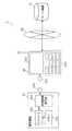
図1は、本実施の形態1における通信システム1の全体像を表した概念図である。 FIG. 1 is a conceptual diagram showing an overall image of a communication system 1 according to the first embodiment.
同図に示すように、通信システム1は、端末機器10と、中継機器20と、ネットワーク30と、サーバ機器31とを備えている。なお、端末機器10は、請求の範囲に記載の「通信端末装置」に相当し、中継機器20は、請求の範囲に記載の「通信装置」に相当する。また、中継機器20は、例えばスマートフォンなどの携帯端末である。 As illustrated in FIG. 1, the communication system 1 includes a
端末機器10と中継機器20とは、近接無線通信によって通信可能である。本実施の形態における近接無線通信とは、電磁誘導方式の13.56MHz帯(HF帯)や電波方式の52〜954MHz帯(UHF帯)などのRFID(Radio Frequency Identification、ISO 14443)タグとリーダライタとの通信や、13.56MHz帯のNFC(Near Field Communication、ISO/IEC 21481)による通信を想定している。通常、HF帯では数10cm、UHF帯では数cmの通信距離に限られるため、端末機器10に中継機器20をかざす(あるいはタッチする)ことによって通信を確立する。 The
本実施の形態では、端末機器10側にリーダライタ機能を実装し、中継機器20側にICタグ機能を有する構成であってもよいし、本実施の形態の主眼は、端末機器10と中継機器20とが互いに近接無線通信によって情報のやりとりができる構成であればよいので、端末機器10側にICタグ機能を実装し、中継機器20側にリーダライタ機能を有する構成であってもよい。また、NFCでは、Peer−to−Peer通信機能や、タグエミュレーション、リーダライタエミュレーションが規格化されており、この場合には、ICタグとリーダライタとの関係はどちらでもよいことになる。 In the present embodiment, the reader / writer function may be mounted on the
(中継機器20の構成の説明)
中継機器20は、ループアンテナ201と、表示部202と、入力部203とを備えている。(Description of the configuration of the relay device 20)
The
ループアンテナ201は、端末機器10のICタグまたはリーダライタと近接無線通信を行うためのアンテナである。つまり、ループアンテナ201は、端末機器10から発せられる電波を受信するアンテナである。なお、ループアンテナ201は、請求の範囲に記載の「アンテナ部」に相当する。 The
表示部202は、端末機器10との近接無線通信の結果や、サーバ機器31からの送信データを表示する部分であり、液晶ディスプレイなどで構成される。 The
入力部203は、中継機器20をユーザが操作するためのインタフェースである。 The
なお、中継機器20の詳細な説明は、後述する。 A detailed description of the
(端末機器10の構成の説明)
端末機器10は、コントローラ101と、メモリ102と、近接無線通信部103と、ループアンテナ104とを備えている。(Description of the configuration of the terminal device 10)
The
コントローラ101は、端末機器10のシステムコントローラであるCPUであり、少なくとも端末機器10の近接無線通信以外のシステムコントロールを行う部分である。 The
メモリ102は、コントローラ101で動作するための制御ソフトや、端末機器10でセンシングするあらゆるデータを記憶可能な不揮発性メモリを含むメモリである。なお、メモリ102は、コントローラ101のLSI内部に実装されていてもよく、外付けメモリであってもよい。メモリ102は、内部に、書き換え不可能なROM領域と、書き換え可能なRAM領域と、コントローラ101の制御手順を記したファームウェア(FW)を格納したFW領域とを具備している。 The
図2は、本実施の形態1におけるメモリ102に記憶される情報を示した概念図である。 FIG. 2 is a conceptual diagram showing information stored in the
同図に示すように、ROM領域には、端末機器固有情報1001、サーバアクセス情報1002、及びアプリケーション識別情報1003などが記録されている。 As shown in the figure, terminal device
端末機器固有情報1001は、端末機器10を識別可能な端末装置識別情報(製造番号)や端末装置型番(製造品番)、製造メーカ識別情報、生産ロット識別情報生産日などの情報である。 The terminal device
サーバアクセス情報1002は、サーバアドレス(URL(Uniform Resource Locator))やサーバ認証情報(アカウント,パスワード)などの情報である。 The
アプリケーション識別情報1003は、中継機器20から受信する情報を処理するアプリケーションを識別する情報である。なお、アプリケーション識別情報1003は、請求の範囲に記載の「ソフトウェア識別情報」に包含される。 The
なお、これらの情報は、端末機器10の生産工程の中で記録される。これによって、A社製の端末機器情報がA社とは別のB社のサーバに転送されるということを回避することが可能となる。 These pieces of information are recorded during the production process of the
つまり、メーカとしては、自社製品のユーザ使用履歴などは、他社へ漏洩させたくない貴重なデータであるため、端末機器10に応じたサーバに接続することが重要となり、メモリ102のROM領域にサーバアクセス情報1002を記録することで、端末機器10に応じたサーバへの接続を実現することができる。そして、端末機器10は、これらの情報を、中継機器20を介してサーバ機器31に送信することによって、メーカ側で端末機器10を識別することが可能となる。 In other words, for the manufacturer, since the user usage history of the company's product is valuable data that should not be leaked to other companies, it is important to connect to a server corresponding to the
RAM領域には、端末機器10の使用履歴情報やエラー情報などが記録される。 In the RAM area, usage history information and error information of the
FW領域には、コントローラ101の制御手順であるファームウェアが記録される。FW領域は、ROMメモリでも構わないし、RAMメモリでも構わない。 Firmware that is a control procedure of the
図1に戻り、近接無線通信部103は、中継機器20に実装されているリーダライタまたはICタグと通信を行う部分であり、ICタグへの転送データを変調したり、ICタグからの転送データを復調したりする部分である。 Returning to FIG. 1, the proximity
なお、中継機器20にリーダライタが実装されていれば、リーダライタへの転送データを変調したり、リーダライタからの転送データを復調したりする。また、近接無線通信部103は、中継機器20のリーダライタから受信した電波に基づいて、少なくとも近接無線通信を確立するための電力生起を行ったり、リーダライタからの電波に基づいてクロック信号を抽出したりする。 If a reader / writer is mounted on the
よって、端末機器10の少なくとも近接無線通信部103は、リーダライタからの電波で電力生起を行ったりクロック信号を抽出したりするので、端末機器10の主電源がオフの状態においても、中継機器20と近接無線通信を行うことが可能である。 Therefore, since at least the close proximity
ループアンテナ104は、中継機器20のリーダライタまたはICタグと近接無線通信を行うためのループアンテナである。例えば、端末機器10は、ループアンテナ104を介して、中継機器20に備えられるICタグに向けてポーリングを行い、通信が確立した時点で、中継機器20から情報を読み出したり、中継機器20へ情報を書き込んだりする。 The
ここで、コントローラ101の動作を詳細に説明する。 Here, the operation of the
コントローラ101は、端末機器10のループアンテナ104に中継機器20のループアンテナ201が近接し、端末機器10と中継機器20との間で近接無線通信が確立したことを検出すると、メモリ102に格納されている端末機器固有情報1001、サーバアクセス情報1002及びアプリケーション識別情報1003を読み出し、中継機器20へ送信する。 When the
(サーバ機器31の構成の説明)
サーバ機器31は、データベース等を記憶している記憶装置を備えたサーバであり、中継機器20と通信ネットワークを介して接続されている。サーバ機器31は、通常は、データベースをもったWEBサーバである。サーバ機器31は、中継機器20から転送されてくる情報をデータベースに登録して、その結果情報を、中継機器20に転送し、表示部202に表示させる。なお、サーバ機器31は、請求の範囲に記載の「登録装置」の機能を包含する。(Description of configuration of server device 31)
The
以上のような通信システム1の構成によって、端末機器10でセンシングした情報を中継機器20を介して、サーバ機器31のデータベースに登録することができる。 With the configuration of the communication system 1 as described above, information sensed by the
例えば、端末機器10から製造番号や型番、メーカ識別情報といった端末機器を唯一に識別可能な情報を近接無線通信で中継機器20に転送する。そして、中継機器20では、近接無線通信を介して端末機器10から受信した情報に、中継機器20が保持しているユーザや中継機器20そのものを特定するための情報(メールアドレス、電話番号、携帯識別情報、SIM(Subscriber Identity Module Card)カードID等)や、中継機器20が位置情報をセンシングできる場合には位置を特定するための情報(GPS(Global Positioning System)情報、A−GPS(Assisted−GPS)情報、携帯網の基地局から推定される位置情報等)とともにサーバ機器31に転送する。そして、サーバ機器31でこれらの情報をデータベース登録することによって、ユーザに様々な情報の入力負担を無くし、実質、中継機器20を端末機器10にかざすだけで、端末機器10のサーバ機器31への愛用者登録などを行うことができる。 For example, information that can uniquely identify a terminal device such as a manufacturing number, a model number, and manufacturer identification information is transferred from the
また、端末機器10のセンシング情報として、不具合発生状況や使用履歴情報を送ることによって、メーカでは、特定ロットの初期不良を迅速に判断し、対処できる他、使用履歴情報からユーザごとに使用されている機能を導き、次期商品開発に利用するなどのメーカメリットを得ることが可能となる。 In addition, by sending failure occurrence status and usage history information as sensing information of the
(中継機器20の詳細な説明)
次に、本発明の実施の形態1における中継機器20について、図面を用いて詳細に説明する。(Detailed description of relay device 20)
Next, the
図3は、本実施の形態1における中継機器20の構成を示したブロック図である。 FIG. 3 is a block diagram illustrating a configuration of the
中継機器20は、携帯電話なら携帯電話機能、パーソナルコンピュータ(PC)ならPC機能を果たす部分である。本実施の形態の中継機器20は、携帯電話端末、PCのすべてを対象とする。よって、本実施の形態では、ひとつひとつの機器の説明は省略し、それぞれに共通の機能のみを説明する。 The
同図に示すように、中継機器20は、ループアンテナ201の他に、近接無線通信部204と、コントローラ205と、メモリ206と、通信部207とを備えている。 As shown in the figure, the
近接無線通信部204は、端末機器10が具備する近接無線通信部103と同等の処理部である。具体的には、近接無線通信部204は、ループアンテナ201を介して端末機器10と近接無線通信を行い、端末機器10からの情報を受信する。 The near
ここで、近接無線通信部204が端末機器10から受信する情報は、メモリ102に記憶されている端末機器固有情報1001、サーバアクセス情報1002、及び端末機器10に関する処理を行うアプリケーションを識別するアプリケーション識別情報1003などである。 Here, the information received from the
なお、端末機器固有情報1001または端末機器固有情報1001に含まれる情報は、請求の範囲に記載の「端末識別情報」に相当する。また、サーバアクセス情報1002は、請求の範囲に記載の「記憶装置識別情報」に包含される。 Note that the terminal device
コントローラ205は、少なくとも近接無線通信部204の動作を制御したり、取得した情報をメモリ206へ格納したりするように指示するシステムコントローラであり、所謂、マイコンやCPUで構成される。 The
具体的には、コントローラ205は、近接無線通信部204が受信したアプリケーション識別情報1003に対応するアプリケーションである対応ソフトウェアを取得し、取得した当該対応ソフトウェアを起動させる。さらに具体的には、コントローラ205は、メモリ206に対応ソフトウェアが記憶されている場合に、メモリ206から対応ソフトウェアを取得し、当該対応ソフトウェアを起動させる。 Specifically, the
また、コントローラ205は、対応ソフトウェアを起動させるとともに、近接無線通信部204が受信した端末機器固有情報1001を少なくとも含む情報を、中継機器20を識別する通信装置識別情報に関連付けて、サーバ機器31へ送信する。なお、コントローラ205は、請求の範囲に記載の「制御部」に相当する。 In addition, the
メモリ206は、内部に書き換え不可能なROM領域と、書き換え可能なRAM領域と、コントローラ205の制御手順を記したファームウェア(FW)を格納したFW領域とを備えている。なお、メモリ206は、請求の範囲に記載の「記憶部」に相当する。 The
図4は、本実施の形態1におけるメモリ206に記憶される情報を示した概念図である。 FIG. 4 is a conceptual diagram showing information stored in the
同図に示すように、ROM領域には、中継機器20の製造時に工程にて書き込まれる中継機器識別情報(製造番号)2011と、中継機器20を使用する人を識別可能な使用者識別情報(SIMカードID等)2012と、中継機器型番(製造品番)2013などが記憶されている。なお、中継機器識別情報2011、使用者識別情報2012及び中継機器型番2013は、請求の範囲に記載の「通信装置識別情報」に包含される。 As shown in the figure, in the ROM area, relay device identification information (manufacturing number) 2011 written in the process when the
なお、本ROM領域の情報は、中継機器20の生産時に書き込まれている。また、本ROM領域は、物理的には書き換え可能なフラッシュメモリなどで構成されていても構わないが、その場合は、端末機器10のリーダライタからはリードオンリーの領域として管理される。これによって、不正に識別情報を書き換えて成りすましをしたり、不正なサーバアクセス情報に書き換えたりするなどの悪意ある操作を防止することができ、セキュリティを向上させることが可能である。 The information in this ROM area is written when the
RAM領域には、例えば端末機器10の愛用者登録などを行うためのアプリケーションソフト2014や、サーバアクセス情報2015が記録される。ここで、サーバアクセス情報2015は、端末機器10から近接無線通信を介して読み出されたサーバアクセス情報1002が記憶された情報であり、中継機器20を介してサーバ機器31に転送される情報である。 In the RAM area, for example,
また、サーバアクセス情報2015には、サーバアドレス(URL)2016及びサーバ認証情報(アカウント、パスワード)が含まれる。なお、サーバアドレス(URL)2016は、請求の範囲に記載の「登録装置識別情報」に包含される。 The
FW領域には、コントローラ205の制御手順であるファームウェアが記録されている。なお、FW領域は、ROMメモリでも構わないし、RAMメモリでも構わない。ただし、FW領域は、後述するファームウェアの更新機能を具備させるためにはRAMメモリが望ましいため、本実施の形態ではRAMメモリとして説明する。 Firmware that is a control procedure of the
図3に戻り、通信部207は、サーバ機器31とインターネットや携帯電話網などの汎用のネットワークを介して通信を行う処理部であり、所定のデータを送信または受信したり、アプリケーションソフト2014をダウンロードしたりする際に使用される。 Returning to FIG. 3, the
次に、中継機器20の動作について、説明する。 Next, the operation of the
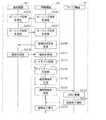
図5は、本実施の形態1における中継機器20の動作の一例を示すフローチャートである。 FIG. 5 is a flowchart illustrating an example of the operation of the
同図に示すように、まず、近接無線通信部204は、ループアンテナ201を介して端末機器10と近接無線通信を行い、端末機器10からの情報を受信する(S102)。 As shown in the figure, first, the proximity
そして、コントローラ205は、近接無線通信部204が受信した情報に含まれるアプリケーション識別情報1003に対応する対応ソフトウェアがメモリ206に記憶されている場合に、メモリ206から当該対応ソフトウェアを取得し、起動させる(S104)。 Then, when the corresponding software corresponding to the
ここで、端末機器10、中継機器20及びサーバ機器31の動作の関係について、より詳細に説明する。 Here, the operation relationship among the
図6Aは、本実施の形態1における端末機器10、中継機器20及びサーバ機器31の動作の一例を示すシーケンス図である。具体的には、同図は、端末機器10がICタグ機能を実装し、中継機器20がリーダライタ機能を有する構成の場合の端末機器10、中継機器20及びサーバ機器31の動作の一例を示すシーケンス図である。 FIG. 6A is a sequence diagram illustrating an example of operations of the
同図に示すように、まず、中継機器20の近接無線通信部204は、ループアンテナ201を介して、端末機器10へポーリング信号を送信する(S201)。なお、中継機器20は、一定時間間隔でポーリング信号を送信することにしてもよいし、端末機器10からのポーリング信号を受信しない場合にポーリング信号を送信することにしてもよいし、ユーザからの操作に基づいてポーリング信号を送信することにしてもよい。また、中継機器20がICタグ機能の動作を行っている場合には、中継機器20がICタグ機能からリーダライタ機能への切り替えを行う、または、ユーザの設定によってリーダライタ機能へ切り替えられることで、ポーリング信号を送信することにしてもよい。 As shown in the figure, first, the near
そして、端末機器10の近接無線通信部103は、中継機器20からのポーリング信号を受信し(S203)、中継機器20へポーリング応答を送信する(S205)。そして、中継機器20の近接無線通信部204は、端末機器10からのポーリング応答を受信し(S207)、端末機器10との近接無線通信を確立する。 Then, the close proximity
このように、中継機器20が端末機器10に対してポーリング信号を送信することで中継機器20と端末機器10との近接無線通信が確立した場合は、中継機器20がリーダライタ機能を有する機器として動作し、端末機器10がICタグ機能を有するタグ機器として動作する。つまり、この場合には、中継機器20は、端末機器10がタグ機器であると判断し、リーダライタ機器として動作する。 As described above, when the proximity wireless communication between the
近接無線通信が確立すると、中継機器20の近接無線通信部204は、端末機器10に、端末機器固有情報1001、サーバアクセス情報1002及びアプリケーション識別情報1003を少なくとも含む情報の送信を要求する(S209)。 When the proximity wireless communication is established, the proximity
これにより、端末機器10の近接無線通信部103は、ループアンテナ104を介して中継機器20に当該情報を送信し(S210)、中継機器20の近接無線通信部204は、ループアンテナ201を介して端末機器10から当該情報を受信する(S212)。このように、端末機器10がタグ機器の場合には、中継機器20をリーダライタ機器として動作させることで、端末機器10と中継機器20との近接無線通信を確立させ、当該情報を受信することができる。 Thereby, the proximity
そして、中継機器20のコントローラ205は、近接無線通信部204が受信した情報をメモリ206に記憶させる(S214)。ここでは、コントローラ205は、端末機器固有情報1001及びアプリケーション識別情報1003をメモリ206に一時的に記憶させるとともに、サーバアクセス情報1002をメモリ206のサーバアクセス情報2015に書き込む。 Then, the
そして、コントローラ205は、メモリ206に記憶されているアプリケーションソフト2014から、アプリケーション識別情報1003に対応するアプリケーションを取得し、取得したアプリケーションを起動させる(S216)。ここで、起動されるアプリケーションは、端末機器10の愛用者登録を行うためのアプリケーションである。なお、本実施の形態では、アプリケーションソフト2014に、アプリケーション識別情報1003に対応するアプリケーションが含まれていることとする。 Then, the
次に、コントローラ205は、起動されたアプリケーションの動作に従って、メモリ206に記憶されている中継機器識別情報2011、使用者識別情報2012及び中継機器型番2013の少なくとも1つと端末機器固有情報1001とを少なくとも含む情報を、通信情報として生成する(S218)。 Next, the
そして、中継機器20の通信部207は、当該アプリケーションの動作に従って、サーバアクセス情報2015のサーバアドレス(URL)2016を参照して、サーバアドレス(URL)2016で示されるサーバ機器31に接続して、当該通信情報を送信する(S220)。 Then, the
通信情報を受信したサーバ機器31は、当該通信情報に含まれる中継機器識別情報2011、使用者識別情報2012または中継機器型番2013に対応付けて、端末機器固有情報1001をデータベースに登録する(S222)。これにより、端末機器10の愛用者登録を行うことができる。 The
そして、サーバ機器31は、登録完了通知を中継機器20に送信し(S224)、登録完了通知を受信した中継機器20は、表示部202に登録完了の表示をさせ(S226)、処理を終了する。 Then, the
(実施の形態1の変形例)
次に、実施の形態1の変形例について、説明する。上記実施の形態1では、図6Aにおいて、端末機器10がICタグ機能を実装し、中継機器20がリーダライタ機能を有する構成であることとした。しかし、本変形例では、端末機器10がリーダライタ機能を実装し、中継機器20がICタグ機能を有する構成であることとする。(Modification of Embodiment 1)
Next, a modification of the first embodiment will be described. In the first embodiment, in FIG. 6A, the
図6Bは、本実施の形態1の変形例における端末機器10、中継機器20及びサーバ機器31の動作の一例を示すシーケンス図である。具体的には、同図は、端末機器10がリーダライタ機能を実装し、中継機器20がICタグ機能を有する構成の場合の端末機器10、中継機器20及びサーバ機器31の動作の一例を示すシーケンス図である。 FIG. 6B is a sequence diagram illustrating an example of operations of the
同図に示すように、まず、端末機器10の近接無線通信部103は、ループアンテナ104を介して、中継機器20へポーリング信号を送信する(S202)。なお、端末機器10は、一定時間間隔でポーリング信号を送信することにしてもよいし、中継機器20からのポーリング信号を受信しない場合にポーリング信号を送信することにしてもよいし、ユーザからの操作に基づいてポーリング信号を送信することにしてもよい。また、端末機器10がICタグ機能の動作を行っている場合には、端末機器10がICタグ機能からリーダライタ機能への切り替えを行う、または、ユーザの設定によってリーダライタ機能へ切り替えられることで、ポーリング信号を送信することにしてもよい。 As shown in the figure, first, the close proximity
そして、中継機器20の近接無線通信部204は、端末機器10からのポーリング信号を受信し(S204)、端末機器10へポーリング応答を送信する(S206)。そして、端末機器10の近接無線通信部103は、中継機器20からのポーリング応答を受信し(S208)、中継機器20との近接無線通信を確立する。 The proximity
このように、端末機器10が中継機器20に対してポーリング信号を送信することで端末機器10と中継機器20との近接無線通信が確立した場合は、端末機器10がリーダライタ機能を有する機器として動作し、中継機器20がICタグ機能を有するタグ機器として動作する。つまり、この場合には、中継機器20は、端末機器10がリーダライタ機器であると判断し、タグ機器として動作する。 As described above, when the close proximity wireless communication between the
近接無線通信が確立すると、端末機器10の近接無線通信部103は、ループアンテナ104を介して中継機器20に端末機器固有情報1001、サーバアクセス情報1002及びアプリケーション識別情報1003を少なくとも含む情報を送信し(S210)、中継機器20の近接無線通信部204は、ループアンテナ201を介して端末機器10から当該情報を受信する(S212)。このように、端末機器10がリーダライタ機器の場合に、中継機器20をタグ機器として動作させることで、端末機器10と中継機器20との近接無線通信を確立させ、当該情報を受信することができる。 When the proximity wireless communication is established, the proximity
そして、以降の処理(S214〜S226)が行われるが、これらの処理については、図6Aに示した処理(図6AのS214〜S226)と同じ処理であるため、詳細な説明は省略する。 Then, the subsequent processes (S214 to S226) are performed. Since these processes are the same as the processes shown in FIG. 6A (S214 to S226 in FIG. 6A), detailed description thereof is omitted.
なお、当該処理(S214〜S226)の間に、中継機器20がタグ機器からリーダライタ機器に切り替わることで、端末機器10がポーリング信号を送信し続けなくともよくなるため、電力の消費を低減することができる。例えば、中継機器20は、アプリケーションを起動(S216)する際に、タグ機器からリーダライタ機器への切り替えを行う。 In addition, since the
以上の構成により、次のような場合に有効に機能する。 The above configuration functions effectively in the following cases.
例えば、ユーザが端末機器10のループアンテナ104に中継機器20のループアンテナ201を近接させ、端末機器10と中継機器20との間で近接無線通信が確立すると、端末機器10は、メモリ102に格納されている端末機器固有情報1001、サーバアクセス情報1002及びアプリケーション識別情報1003を、中継機器20へ送信する。 For example, when the user brings the
これにより、例え中継機器20側で格納されたアプリケーションが予め起動されていなくても、アプリケーション識別情報1003を基に所定のアプリケーションが起動し、所望の端末機器固有情報1001と中継機器識別情報2011と使用者識別情報2012と中継機器型番2013等の情報を、サーバアクセス情報1002に記載された場所にあるサーバ機器31へ送信することが可能となる。すなわち、ユーザは、中継機器20でわざわざアプリケーションを起動させることなく、端末機器10の情報をサーバ機器31へ登録することができる。 Thereby, even if the application stored on the
つまり本実施の形態及びその変形例に係る中継機器20によれば、近接無線通信によって、情報を処理するためのアプリケーションを識別するアプリケーション識別情報1003を受信し、当該アプリケーション識別情報1003に対応するアプリケーションを取得して、起動させる。つまり、端末機器10と中継機器20との近接無線通信を確立させるだけで、受信した情報を処理するためのアプリケーションを起動させることができる。このため、近接無線通信を介して端末機器10から受信した情報を、ユーザの煩雑な操作を必要とすることなく処理することができる。また、中継機器20に常に当該アプリケーションを起動させておく必要がないので、使用電力の低減を行うことができる。 In other words, according to the
また、アプリケーション識別情報1003に対応するアプリケーションがメモリ206に記憶されている場合に、メモリ206から当該アプリケーションを取得し、起動させる。つまり、端末機器10と中継機器20との近接無線通信を確立させるだけで、メモリ206に記憶されているアプリケーションが自動的に起動して、受信した情報を処理する。このため、近接無線通信を介して端末機器10から受信した情報を、ユーザの煩雑な操作を必要とすることなく処理することができる。 When an application corresponding to the
また、端末機器10と中継機器20との近接無線通信を確立させるだけで、端末機器10の識別情報を少なくとも含む情報を中継機器20の識別情報に関連付けて、サーバ機器31へ送信する。このため、ユーザによる1度のタッチ操作によって、近接無線通信を介して端末機器10から受信した情報を処理して、外部のサーバ機器31に端末機器10の情報を登録することができる。 In addition, information including at least the identification information of the
なお、本実施の形態及びその変形例では、端末機器10のループアンテナ104と中継機器20のループアンテナ201とを近接させた際に、端末機器固有情報1001とサーバアクセス情報1002とアプリケーション識別情報1003とを端末機器10が中継機器20へ送信しているが、アプリケーション識別情報1003のみを送信することにしてもよい。 In the present embodiment and its modifications, when the
この場合、コントローラ101は近接無線通信部103をICタグモードに切り替え、中継機器20のコントローラ205は所定のアプリケーションを起動し、さらに近接無線通信部204をリーダライタモードに切り替え、その後はアプリケーションの動作に従い、中継機器20が端末機器固有情報1001やサーバアクセス情報1002を読み出すことができる。これにより、端末機器10と中継機器20とが1度にやりとりする情報量が少なくて済む。 In this case, the
なお、本実施の形態の変形例において、近接無線通信部103を起動し、中継機器20に対して近接無線通信を行うためのポーリング動作を開始するボタンを、端末機器10に設けてもよい。通常、ポーリング動作は、不特定の相手に対して電波を出し続けるので、バッテリ駆動の携帯機器等では電池寿命の観点で負担が生じる。従って、ポーリング動作を行わせるための専用ボタンを配置すれば、無駄なポーリング動作を行わせないことができる。 In the modification of the present embodiment, the
(実施の形態2)
次に、本発明における実施の形態2について、図面を用いて詳細に説明する。上記実施の形態1では、中継機器20には、アプリケーション識別情報1003に対応したアプリケーションが予めインストールされており、当該アプリケーションが自動起動されることとした。しかし、本実施の形態2では、当該アプリケーションが予めインストールされていない場合でも、サーバ機器31から当該アプリケーションを受信し、起動する。(Embodiment 2)
Next, a second embodiment of the present invention will be described in detail with reference to the drawings. In the first embodiment, an application corresponding to the
ここで、本実施の形態2における通信システムは、実施の形態1における図1に示された通信システム1の中継機器20の代わりに携帯機器5000を備えている。このため、以下では、携帯機器5000の構成について、詳細に説明する。 Here, the communication system according to the second embodiment includes a
図7は、本実施の形態2における中継機器である携帯電話などの携帯機器5000の構成を示すブロック図である。 FIG. 7 is a block diagram illustrating a configuration of a
同図に示すように、携帯機器5000は、端末部5001と近接無線通信部5002とを備えており、端末部5001と近接無線通信部5002とは、端末部5001のシステムコントローラ5010により接続される。なお、携帯機器5000は、請求の範囲に記載の「通信装置」に相当し、例えばスマートフォンなどの携帯端末である。 As shown in the figure, the
端末部5001は、インターネットや携帯移動網を介して、サーバ機器31と接続されるとともに、近接無線通信部5002と、シリアルインタフェースや内部バスによって接続される部分である。 The
端末部5001は、システムコントローラ5010、メモリ部5011、アプリ管理部5015及び通信部5019を備えている。なお、システムコントローラ5010及びアプリ管理部5015は、請求の範囲に記載の「制御部」に包含される。 The
システムコントローラ5010は、端末部5001のシステムコントローラであり、近接無線通信部5002と接続されているとともに、端末部5001の各構成要素の制御を行う。システムコントローラ5010が行う制御の詳細な説明については、後述する。 A
メモリ部5011は、アプリメモリ5012、機器情報メモリ5013及び汎用メモリ5014を含むメモリである。なお、メモリ部5011は、請求の範囲に記載の「記憶部」に相当する。 The
アプリメモリ5012は、端末部5001にインストールされているアプリケーションを記憶する部分であり、不揮発性メモリで構成される。 The
機器情報メモリ5013は、後述する端末部5001の機器情報を記憶する部分である。詳細は後述するが、機器情報とは携帯機器5000の端末識別情報、電話番号、メールアドレス、契約者IDなどにより構成される情報である。 The
汎用メモリ5014は、近接無線通信で受信した端末通信情報や、通信部5019でサーバ機器31から受信した情報を、一時的に記憶するメモリで構成される。 The general-
アプリ管理部5015は、端末部5001にインストールされるアプリケーションを管理する処理部であり、アプリインストール部5016、アプリ判定部5017及びアプリ起動部5018を備えている。 The
アプリ判定部5017は、近接無線通信部5002を介して受信した端末通信情報に含まれるアプリ識別情報に基づいて、端末部5001のアプリメモリ5012に、当該アプリ識別情報に対応するアプリケーションが記憶されているか否かを判定する。ここで、アプリ識別情報とは、端末機器10から受信する情報を処理するためのソフトウェアを識別する識別情報である。 Based on the application identification information included in the terminal communication information received via the proximity
アプリインストール部5016は、アプリ識別情報に対応するアプリケーションがアプリメモリ5012に記憶されていないとアプリ判定部5017が判定した場合には、近接無線通信部5002が受信する端末通信情報で示されるアプリダウンロードURLに基づいて、アプリケーションが格納されているサーバ機器31に接続する。 If the
ここで、サーバ機器31は、情報登録用のデータベースに加え、ソフトウェア(アプリケーション)を記憶している。つまり、サーバ機器31は、請求の範囲に記載の「記憶装置」及び「登録装置」の機能を包含する。なお、通信システム1は、ソフトウェアを記憶しているサーバ機器(請求の範囲に記載の「記憶装置」に相当)と、情報を登録するためのサーバ機器(請求の範囲に記載の「登録装置」に相当)の2つのサーバ機器を備えていることにしてもよい。 Here, the
そして、アプリインストール部5016は、通信部5019を介して、接続したサーバ機器31に、当該アプリケーションを送信するよう依頼するソフトウェア送信依頼信号を送信することで、サーバ機器31から当該アプリケーションを取得する。そして、アプリインストール部5016は、当該アプリケーションをダウンロードして、アプリメモリ5012にインストールする。なお、ソフトウェア送信依頼信号には、アプリ識別情報と携帯機器5000を識別する識別情報とが含まれる。 Then, the
アプリ起動部5018は、近接無線通信部5002を介して受信した端末通信情報に含まれるアプリ識別情報に基づいて、端末部5001のアプリメモリ5012に格納されているアプリケーションを起動する。アプリ起動部5018は、アプリ判定部5017によって、受信したアプリ識別情報に対応するアプリケーションが、アプリメモリ5012にインストールされていると判定された場合にのみ、動作を行う。 The
具体的には、アプリ起動部5018は、アプリメモリ5012にアプリ識別情報に対応するアプリケーションが記憶されているとアプリ判定部5017が判定した場合には、アプリメモリ5012から当該アプリケーションを取得し、起動する。 Specifically, when the
また、アプリ起動部5018は、アプリメモリ5012にアプリ識別情報に対応するアプリケーションが記憶されていないとアプリ判定部5017が判定した場合には、アプリインストール部5016がサーバ機器31からダウンロードしてアプリメモリ5012にインストールしたアプリケーションを取得し、起動する。 If the
通信部5019は、近接無線通信部5002で受信した端末通信情報に含まれるサーバ機器31のURLに応じて、URLの示すサーバ機器31に接続して、サーバ機器31から情報を受信したり、サーバ機器31へ情報を送信したりする処理部である。通信部5019は、下記の2つの動作モードを備える。 The
第1のモードは、アプリケーションのインストールモードである。 The first mode is an application installation mode.
このモードでは、近接無線通信部5002が受信した端末通信情報に含まれるアプリ識別情報で示される通信部5019は、アプリケーションがアプリメモリ5012にインストールされていないとアプリ判定部5017によって判定された場合、端末通信情報に含まれるアプリダウンロードURLが示すサーバ機器31に接続する。そして、通信部5019は、当該サーバ機器31から、アプリ識別情報が示すアプリケーションをダウンロードして、アプリインストール部5016に送信する。 In this mode, when the
なお、アプリインストール部5016は、ダウンロードしたアプリケーションを受信すると、アプリメモリ5012に当該アプリケーションのインストールを行う。 When the
また、通信部5019の第2のモードは、サーバ機器31への登録モードである。 The second mode of the
このモードでは、通信部5019は、アプリ起動部5018がアプリ識別情報で示されるアプリケーションを起動後、近接無線通信部5002で受信され汎用メモリ5014に記憶されている端末通信情報のアクセス情報が示す登録データベースURLに基づいて、サーバ機器31に接続する。そして、通信部5019は、端末通信情報に含まれている端末機器10を識別する端末情報に、機器情報メモリ5013に記憶されている通信機器情報を対応させて、携帯通信情報を生成し、サーバ機器31に送信する。 In this mode, the
次に、携帯機器5000の近接無線通信部5002について説明する。本近接無線通信部5002は、端末機器10と近接無線通信を行う部分であり、ループアンテナ5021、近接通信制御部5022、近接通信メモリ5023及び通信モード切替部5024を備えている。 Next, the proximity
なお、近接無線通信部5002は、一般的なNFC(Near Field Communication)を用いた通信部であり、13.56MHz帯で数十センチの距離で通信を行う処理部である。 The close proximity
また、NFCは、ICカードをエミュレーションするICカードエミュレーションモードと、ICカードのリーダライタをエミュレーションするリーダライタエミュレーションモードとを有する。 NFC also has an IC card emulation mode for emulating an IC card and a reader / writer emulation mode for emulating an IC card reader / writer.
ICカードエミュレーションモードとリーダライタエミュレーションモードとの大きな違いは、ポーリングという呼びかけ動作を行うかどうかである。ポーリングは、不特定のICカードに呼びかけを行うため、絶えず、電波を発する必要がある。一方、ICカードエミュレーションモードは、リーダライタからのポーリングを電波として受信し、受信した電波から生起した電力、クロックで動作を行う。従って、リーダライタとは異なり、絶えず電波を出力することはない。 A major difference between the IC card emulation mode and the reader / writer emulation mode is whether or not a call operation called polling is performed. Since polling calls an unspecified IC card, it is necessary to constantly emit radio waves. On the other hand, in the IC card emulation mode, polling from the reader / writer is received as a radio wave, and the operation is performed with the power and clock generated from the received radio wave. Therefore, unlike a reader / writer, radio waves are not constantly output.
また、一般的な携帯電話に内蔵される近接通信モジュールも、ICカードエミュレーションモードとリーダライタエミュレーションモードとを備える。しかしながら、リーダライタエミュレーションモードで動作させる場合にのみ、携帯電話のアプリケーションを起動することによって、明示的にリーダライタエミュレーションモードに切り替えることが必要となる。アプリケーションの起動がない場合には、通常、ICカードエミュレーションモードで動作する。 A proximity communication module built in a general mobile phone also has an IC card emulation mode and a reader / writer emulation mode. However, only when operating in the reader / writer emulation mode, it is necessary to explicitly switch to the reader / writer emulation mode by activating the application of the mobile phone. When the application is not activated, it normally operates in an IC card emulation mode.
ループアンテナ5021は、外部のリーダライタ機能を有する端末機器10からのポーリング信号を受信し、当該ポーリング信号を出力している端末機器10にポーリング応答を送信することによって、端末機器10との近接無線通信を確立する。なお、ループアンテナ5021は、請求の範囲に記載の「アンテナ部」に相当する。 The
近接通信制御部5022は、ループアンテナ5021が受信した信号を復調したり、ループアンテナ5021を介して端末機器10に送信する情報を変調したりする。 The near field
近接通信メモリ5023は、不揮発性メモリを含み、記憶している内容を外部の端末機器10からのコマンドに応じて、ループアンテナ5021を介して送信したり、ループアンテナ5021で受信した信号を一時的に記憶したりする。また、近接通信メモリ5023には、ROM(Read Only Memory)領域が含まれ、当該領域に近接無線通信部5002固有の識別情報が記録されている。 The near
通信モード切替部5024は、端末部5001からのコマンドによって、近接無線通信部5002をICカードエミュレーションモードからリーダライタエミュレーションモードに切り替える。 The communication
つまり、通信モード切替部5024は、近接無線通信部5002がリーダライタ機能を有するリーダライタ機器と近接無線通信を行うリーダライタエミュレーションモードと、近接無線通信部5002がICタグ機能を有するタグ機器と近接無線通信を行うICカードエミュレーションモードとを切り替える。具体的には、通信モード切替部5024は、端末機器10がリーダライタ機器の場合に、近接無線通信部5002をリーダライタエミュレーションモードに切り替え、端末機器10がタグ機器の場合に、近接無線通信部5002をICカードエミュレーションモードに切り替える。 That is, the communication
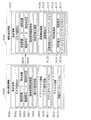
図8は、本発明の実施の形態2における携帯機器5000が受信する端末通信情報6000と携帯機器5000が送信する携帯通信情報6100との構成を示す図である。具体的には、同図は、携帯機器5000が近接無線通信を介して外部の端末機器10から受信する端末通信情報6000と、携帯機器5000から通信部5019を介してサーバ機器31に送信する携帯通信情報6100との構成を示した概念図である。 FIG. 8 is a diagram showing configurations of
同図に示すように、端末通信情報6000には、端末情報6001、アプリアクセス情報6009及びアクセス情報6012が含まれる。 As shown in the figure, the
端末情報6001には、端末機器10の近接無線通信部103ごとに固有のICタグ個別ID6002、端末機器10の種別を識別可能な端末型番6003、端末機器10の個体を識別可能な端末品番6004、端末機器10の製造メーカを特定可能な製造者ID6005、端末機器10の製造年月日6006、端末機器10がユーザに操作された使用履歴情報を示す端末使用履歴情報6007及び端末機器に生じている不具合を特定するための端末不具合情報6008が含まれる。なお、端末情報6001または端末情報6001に含まれる情報は、請求の範囲に記載の「端末識別情報」に相当する。 The
アプリアクセス情報6009には、携帯機器5000にインストールされるべきアプリケーションのアプリ識別情報6010及びアプリケーションをダウンロードするサーバ機器31を示すアプリダウンロードURL6011が含まれる。なお、アプリ識別情報6010は、請求の範囲に記載の「ソフトウェア識別情報」に包含される。また、アプリダウンロードURL6011は、請求の範囲に記載の「記憶装置識別情報」に包含される。 The
アクセス情報6012には、端末情報6001などを、携帯機器5000を介してサーバ機器31に登録するための、サーバアドレスを示した登録データベースURL6013が含まれる。なお、登録データベースURL6013は、請求の範囲に記載の「登録装置識別情報」に包含される。 The
一方、携帯通信情報6100は、携帯機器5000とインターネットや携帯移動網を介して接続されるサーバ機器31に、携帯機器5000から送信される情報であり、端末情報6101及び通信機器情報6109が含まれる。 On the other hand, the
端末情報6101は、端末通信情報6000の端末情報6001と同等の情報であり、近接無線通信を介して受信した端末通信情報6000が一時的に記憶される汎用メモリ5014から呼び出されて使用される。 The
また、通信機器情報6109は、機器情報メモリ5013に予め記憶されている情報であり、携帯機器5000ごとに固有に識別可能な情報である通信機器ID6110、図示しないGPS(Global Positioning System)で受信した位置情報6111、インストールされているアプリケーションのバージョン情報であるアプリバージョン6112及び利用者情報6113が含まれる。なお、通信機器情報6109または通信機器情報6109に含まれる情報は、請求の範囲に記載の「通信装置識別情報」に相当する。 The
利用者情報6113は、携帯機器5000を使用するユーザを識別可能な情報として、携帯機器5000のSIMカードに記録されている契約者ID6114、携帯機器5000の電話番号6115、携帯機器のメールアドレス6116及び登録データベースのサーバで利用者を識別するためのサービスアカウント6117が含まれる。 The
次に、携帯機器5000の代表的な動作を説明する。 Next, typical operations of the
図9は、本実施の形態2における携帯機器5000の動作の一例を示すフローチャートである。 FIG. 9 is a flowchart illustrating an example of the operation of the
同図に示すように、まず、近接無線通信部5002は、ループアンテナ5021を介して端末機器10と近接無線通信を行い、端末機器10から端末通信情報6000を受信する(S302)。 As shown in the figure, first, the proximity
具体的には、近接無線通信部5002は、外部のリーダライタ機能を有する端末機器10からのポーリング信号を受信すると、ポーリング信号を出力した端末機器10に対してポーリング応答を返し、近接無線通信を確立する。そして、近接無線通信が確立すると、端末機器10から端末通信情報6000を受信し、受信した端末通信情報6000を一旦、近接通信メモリ5023に一時記憶する。 Specifically, when receiving a polling signal from the
そして、端末通信情報6000の一時記憶が完了すると、端末部5001のシステムコントローラ5010は、近接通信メモリ5023に記憶されている端末通信情報6000を、メモリ部5011の汎用メモリ5014に記憶させる。 When the temporary storage of the
次に、システムコントローラ5010は、端末通信情報6000のアプリアクセス情報6009に示されているアプリ識別情報6010を読み出し、アプリ判定部5017に対して、アプリ識別情報6010が示すアプリケーションがアプリメモリ5012に既にインストールされているか否かを判定させる(S304)。 Next, the
そして、アプリ判定部5017の判定結果、当該アプリケーションがインストールされていると判定された場合には(S304でYES)、システムコントローラ5010は、アプリ起動部5018によって、アプリ識別情報6010の示すアプリケーションをアプリメモリ5012から呼び出し、起動させる(S310)。 If the
一方、アプリ判定部5017の判定結果、当該アプリケーションがインストールされていないと判定された場合には(S304でNO)、システムコントローラ5010は、通信部5019に、端末通信情報6000のアプリアクセス情報6009のアプリダウンロードURL6011に示されているサーバ機器31に接続させる(S306)。 On the other hand, if the determination result of the
そして、システムコントローラ5010は、アプリアクセス情報6009のアプリ識別情報6010の示すアプリケーションを、通信部5019を介してダウンロードして、アプリメモリ5012にインストールを行う(S308)。 Then, the
インストールが完了すれば、システムコントローラ5010は、アプリ起動部5018によって、アプリ識別情報6010の示すアプリケーションをアプリメモリ5012から呼び出し、起動させる(S310)。 When the installation is completed, the
アプリケーションが起動すると、そのアプリケーション動作として、汎用メモリ5014に記憶されている端末通信情報6000のアクセス情報6012から、登録データベースURL6013が読み出され、通信部5019を介して、登録データベースURL6013に示されたサーバ機器31に接続される。そして、当該アプリケーション動作として、端末通信情報6000の端末情報6001に、機器情報メモリ5013に記憶されている通信機器情報6109を対応付けた携帯通信情報6100が生成されて、当該携帯通信情報6100がサーバ機器31に送信される。 When the application is activated, the
次に、端末機器10、携帯機器5000及びサーバ機器31の動作の関係について、より詳細に説明する。 Next, the relationship between operations of the
図10Aは、本実施の形態2における端末機器10、携帯機器5000及びサーバ機器31の動作の一例を示すシーケンス図である。具体的には、同図は、端末機器10がICタグ機能を実装し、携帯機器5000がリーダライタ機能を有する構成の場合の端末機器10、携帯機器5000及びサーバ機器31の動作の一例を示すシーケンス図である。 FIG. 10A is a sequence diagram illustrating an example of operations of the
同図に示すように、まず、携帯機器5000の近接無線通信部5002は、ループアンテナ5021を介して、端末機器10へポーリング信号を送信する(S401)。なお、携帯機器5000は、一定時間間隔でポーリング信号を送信することにしてもよいし、端末機器10からのポーリング信号を受信しない場合にポーリング信号を送信することにしてもよいし、ユーザからの操作に基づいてポーリング信号を送信することにしてもよい。また、携帯機器5000がICタグ機能の動作を行っている場合には、携帯機器5000がICタグ機能からリーダライタ機能への切り替えを行う、または、ユーザの設定によってリーダライタ機能へ切り替えられることで、ポーリング信号を送信することにしてもよい。 As shown in the figure, first, the near
そして、端末機器10の近接無線通信部103は、携帯機器5000からのポーリング信号を受信し(S403)、携帯機器5000へポーリング応答を送信する(S405)。そして、携帯機器5000の近接無線通信部5002は、端末機器10からのポーリング応答を受信し(S407)、端末機器10との近接無線通信を確立する。 Then, the close proximity
このように、携帯機器5000が端末機器10に対してポーリング信号を送信することで携帯機器5000と端末機器10との近接無線通信が確立した場合は、携帯機器5000がリーダライタ機能を有する機器として動作し、端末機器10がICタグ機能を有するタグ機器として動作する。つまり、この場合には、携帯機器5000は、端末機器10がタグ機器であると判断し、リーダライタ機器として動作する。具体的には、携帯機器5000の通信モード切替部5024は、端末機器10がタグ機器の場合に、近接無線通信部5002をICカードエミュレーションモードに切り替える。 As described above, when the wireless communication between the
近接無線通信が確立すると、携帯機器5000の近接無線通信部5002は、端末機器10に、端末情報6001、アプリアクセス情報6009及びアクセス情報6012を含む端末通信情報6000の送信を要求する(S409)。 When the close proximity wireless communication is established, the close proximity
これにより、端末機器10の近接無線通信部103は、ループアンテナ104を介して携帯機器5000に当該情報を送信し(S410)、携帯機器5000の近接無線通信部5002は、ループアンテナ201を介して端末機器10から当該情報を受信する(S412)。このように、端末機器10がタグ機器の場合には、携帯機器5000をリーダライタ機器として動作させることで、端末機器10と携帯機器5000との近接無線通信を確立させ、当該情報を受信することができる。 Thereby, the proximity
そして、携帯機器5000のシステムコントローラ5010は、近接無線通信部5002が受信した端末通信情報6000を、汎用メモリ5014に一時的に記憶させる(S414)。 Then, the
次に、アプリ判定部5017は、汎用メモリ5014に記憶された端末通信情報6000のアプリアクセス情報6009のアプリ識別情報6010に基づいて、アプリメモリ5012にアプリ識別情報6010で示されたアプリケーションがインストールされているか否かを判定する(S416)。 Next, the
そして、アプリ判定部5017によりアプリ識別情報6010が示すアプリケーションがアプリメモリ5012にインストールされていないと判定された場合には、アプリインストール部5016は、汎用メモリ5014に記憶された端末通信情報6000のアプリアクセス情報6009のアプリダウンロードURL6011に基づいて、アプリケーションをダウンロードするためのサーバ機器31に接続する(S418)。 If the
そして、アプリインストール部5016は、通信部5019を介して、接続したサーバ機器31に、当該アプリケーションを送信するよう依頼するソフトウェア送信依頼信号を送信する(S420)。ここで、ソフトウェア送信依頼信号には、アプリ識別情報6010と、通信機器ID6110などの携帯機器5000を識別する情報とが含まれる。 Then, the
そして、サーバ機器31は、ソフトウェア送信依頼信号に含まれるアプリ識別情報6010で示されるアプリケーションの登録状況を確認し(S422)、通信機器ID6110などの携帯機器5000を識別する情報で示される携帯機器5000に、当該アプリケーションを送信する(S424)。 Then, the
そして、アプリインストール部5016は、サーバ機器31からアプリ識別情報6010で示されるアプリケーションをダウンロードして、ダウンロードしたアプリケーションをアプリメモリ5012にインストールする(S426)。 Then, the
次に、アプリ起動部5018は、アプリメモリ5012から当該アプリケーションを取得し、起動する(S428)。なお、同図では図示していないが、アプリ識別情報6010が示すアプリケーションがアプリメモリ5012にインストールされているとアプリ判定部5017が判定した場合は、アプリケーションのダウンロード及びインストールは行われずに、アプリ起動部5018は、アプリ識別情報6010で示されるアプリケーションを起動する(S428)。 Next, the
そして、アプリケーションが起動すれば、当該アプリケーションの動作に従って、通信部5019は、携帯通信情報6100を生成し、送信する(S430)。 And if an application starts, according to the operation | movement of the said application, the
具体的には、通信部5019は、汎用メモリ5014に記憶されている端末通信情報6000の端末情報6001を端末情報6101として、機器情報メモリ5013に記憶されている通信機器情報6109と対応付けて、携帯通信情報6100を生成する。 Specifically, the
また、通信部5019は、携帯通信情報6100を生成すれば、汎用メモリ5014に記憶されている端末通信情報6000のアクセス情報6012に示されている登録データベースURL6013を参照して、端末情報6101を登録するサーバ機器に接続して、携帯通信情報6100をサーバに送信する。ここでは、端末情報6101を登録するサーバ機器は、サーバ機器31であることとするが、サーバ機器31と異なるサーバ機器に端末情報6101を登録させることにしてもよい。 If the
そして、携帯通信情報6100を受信したサーバ機器31は、携帯通信情報6100に含まれる通信機器情報6109に対応付けて、端末情報6101をデータベースに登録する(S432)。通信機器情報6109には、ユーザを特定するための利用者情報が含まれるので、これに対応付けて端末情報6101を登録することによって、端末機器10の愛用者登録を行うことが可能となる。 Then, the
そして、サーバ機器31から登録完了通知を受信した携帯機器5000は、表示部に登録完了の表示をさせ(S434)、処理を終了する。 Then, the
ここで、従来の愛用者登録では、ユーザ自身がハガキやウェブサイトに直接、ユーザの個人情報や購入した端末機器ごとにその製造番号、製品番号を入力する必要があった。そのため、愛用者登録が目論見通り増加することなく、本来の目的を達成するに至らなかった。 Here, in the conventional user registration, it is necessary for the user himself / herself to directly input the serial number and product number of each user's personal information and purchased terminal device on a postcard or website. As a result, the number of user registrations did not increase as expected, and the original purpose was not achieved.
しかしながら、本発明を利用すれば、ユーザは、ワンタッチという簡単操作で、端末機器の愛用者登録を完了することが可能となる。 However, if the present invention is used, the user can complete the user registration of the terminal device with a simple operation of one touch.
また、一般的な携帯電話には、近接通信モジュールが具備されているが、愛用者登録のためのアプリケーションをインストールしたり、アプリケーションを起動してからタッチしたりするなど煩雑な操作が必要であった。 In addition, a general mobile phone is equipped with a proximity communication module, but complicated operations such as installing an application for registering a user or starting the application and then touching it are necessary. It was.
しかしながら、本発明を利用すれば、通常、アプリケーションの起動の必要のないICカードエミュレーションモードで携帯電話の近接通信モジュールを利用することが可能となるとともに、起動すべきアプリケーションがインストールされていないと判定された場合には、近接無線通信を介して、読み出した情報からアプリケーションのダウンロード先を入手して、アプリケーションのインストールを自動化することが可能となる。 However, if the present invention is used, it is possible to use the proximity communication module of the mobile phone in an IC card emulation mode that does not normally require the activation of the application, and it is determined that the application to be activated is not installed. In this case, the application download destination can be obtained from the read information via the proximity wireless communication, and the installation of the application can be automated.
また、インストールが完了すれば、インストールしたアプリケーション動作として、近接無線通信を介して読み出した端末情報を、利用者情報を含む携帯機器の通信機器情報に対応付けて、愛用者登録データベースに送信することによって、ワンタッチという簡単操作で、アプリケーションのインストールから、愛用者登録までの一連の処理を、自動的に行うことが可能となる。 When the installation is completed, as the installed application operation, the terminal information read via the proximity wireless communication is associated with the communication device information of the mobile device including the user information and transmitted to the user registration database. Thus, a series of processing from application installation to user registration can be automatically performed with a simple operation of one touch.
(実施の形態2の変形例)
次に、実施の形態2の変形例について、説明する。上記実施の形態2では、図10Aにおいて、端末機器10がICタグ機能を実装し、携帯機器5000がリーダライタ機能を有する構成であることとした。しかし、本変形例では、端末機器10がリーダライタ機能を実装し、携帯機器5000がICタグ機能を有する構成であることとする。(Modification of Embodiment 2)
Next, a modification of the second embodiment will be described. In the second embodiment, in FIG. 10A, the
図10Bは、本実施の形態2の変形例における端末機器10、携帯機器5000及びサーバ機器31の動作の一例を示すシーケンス図である。具体的には、同図は、端末機器10がリーダライタ機能を実装し、携帯機器5000がICタグ機能を有する構成の場合の端末機器10、携帯機器5000及びサーバ機器31の動作の一例を示すシーケンス図である。 FIG. 10B is a sequence diagram illustrating an example of operations of the
同図に示すように、まず、端末機器10の近接無線通信部103は、ループアンテナ104を介して、携帯機器5000へポーリング信号を送信する(S402)。なお、端末機器10は、一定時間間隔でポーリング信号を送信することにしてもよいし、携帯機器5000からのポーリング信号を受信しない場合にポーリング信号を送信することにしてもよいし、ユーザからの操作に基づいてポーリング信号を送信することにしてもよい。また、端末機器10がICタグ機能の動作を行っている場合には、端末機器10がICタグ機能からリーダライタ機能への切り替えを行う、または、ユーザの設定によってリーダライタ機能へ切り替えられることで、ポーリング信号を送信することにしてもよい。 As shown in the figure, first, the close proximity
そして、携帯機器5000の近接無線通信部5002は、端末機器10からのポーリング信号を受信し(S404)、端末機器10へポーリング応答を送信する(S406)。そして、端末機器10の近接無線通信部103は、携帯機器5000からのポーリング応答を受信し(S408)、携帯機器5000との近接無線通信を確立する。 The proximity
このように、端末機器10が携帯機器5000に対してポーリング信号を送信することで端末機器10と携帯機器5000との近接無線通信が確立した場合は、端末機器10がリーダライタ機能を有する機器として動作し、携帯機器5000がICタグ機能を有するタグ機器として動作する。つまり、この場合には、携帯機器5000は、端末機器10がリーダライタ機器であると判断し、タグ機器として動作する。具体的には、携帯機器5000の通信モード切替部5024は、端末機器10がリーダライタ機器の場合に、近接無線通信部5002をリーダライタエミュレーションモードに切り替える。 As described above, when the wireless communication between the
近接無線通信が確立すると、端末機器10の近接無線通信部103は、ループアンテナ104を介して携帯機器5000に端末情報6001、アプリアクセス情報6009及びアクセス情報6012を含む端末通信情報6000を送信し(S410)、携帯機器5000の近接無線通信部5002は、ループアンテナ5021を介して端末機器10から当該情報を受信する(S412)。このように、端末機器10がリーダライタ機器の場合に、携帯機器5000をタグ機器として動作させることで、端末機器10と携帯機器5000との近接無線通信を確立させ、当該情報を受信することができる。 When the close proximity wireless communication is established, the close proximity
そして、以降の処理(S414〜S434)が行われるが、これらの処理については、図10Aに示した処理(図10AのS414〜S434)と同じ処理であるため、詳細な説明は省略する。 Then, the subsequent processes (S414 to S434) are performed. Since these processes are the same as the processes shown in FIG. 10A (S414 to S434 in FIG. 10A), detailed description thereof is omitted.
なお、当該処理(S414〜S434)の間に、携帯機器5000がタグ機器からリーダライタ機器に切り替わることで、端末機器10がポーリング信号を送信し続けなくともよくなるため、電力の消費を低減することができる。例えば、アプリケーションの起動(S428)に応じて、携帯機器5000をICカードエミュレーションモードからリーダライタエミュレーションモードに切り替える。これによって、端末機器10側をリーダライタエミュレーションモードからICカードエミュレーションモードに切り替えることが可能となり、明示的に端末機器10のポーリング動作を終了させることが可能となり、端末機器10の消費電力を削減することが可能となる。携帯機器5000は、アプリケーションの終了操作に応じてリーダライタエミュレーションモードからICカードエミュレーションモードへ切り替えて、ポーリング動作を終了することが可能となる。 In addition, since the
以上のように、本実施の形態2及びその変形例における携帯機器5000によれば、アプリ識別情報6010に対応するアプリケーションがアプリメモリ5012に記憶されていない場合であっても、外部のサーバ機器から当該アプリケーションを取得し、起動させる。つまり、端末機器10と携帯機器5000との近接無線通信を確立させるだけで、携帯機器5000に所定のアプリケーションが記憶されていない場合においても、携帯機器5000を操作することなく自動的に所定のアプリケーションを起動させて、受信した情報を処理する。このため、近接無線通信を介して端末機器10から受信した情報を、ユーザの煩雑な操作を必要とすることなく処理することができる。また、携帯機器5000のメモリに多くのアプリケーションを保存させておく必要がないので、大きな容量のメモリを必要とせず、メモリ容量の低減を図ることができる。 As described above, according to the
また、端末機器10からアプリダウンロードURL6011を受信して、アプリダウンロードURL6011で示されるサーバ機器に、アプリ識別情報6010を含むソフトウェア送信依頼信号を送信することで、サーバ機器からアプリケーションを取得して起動させる。つまり、サーバ機器へのアクセス情報を端末機器10から受信することで、簡易にサーバ機器にアクセスすることができ、アプリ識別情報6010をサーバ機器に送付することで、簡易にサーバ機器からアプリケーションを取得することができる。このため、複雑な処理を行うことなく、近接無線通信を介して端末機器10から受信した情報を処理することができる。 In addition, the
また、端末機器10がリーダライタ機器の場合に、近接無線通信部5002をリーダライタモードに切り替え、端末機器10がタグ機器の場合に、近接無線通信部5002をタグモードに切り替える。つまり、携帯機器5000にリーダライタ機器またはタグ機器を近づけることによって、携帯機器5000と当該リーダライタ機器またはタグ機器との近接無線通信を確立し、自動的に所定のアプリケーションを起動させることができる。このため、端末機器10がリーダライタ機器であってもタグ機器であっても、近接無線通信を介して端末機器10から受信した情報を、ユーザの煩雑な操作を必要とすることなく処理することができる。 When the
以上、本発明に係る通信装置である中継機器20及び携帯機器5000について、上記実施の形態及びその変形例を用いて説明したが、本発明は、これに限定されるものではない。 As described above, the
つまり、今回開示された実施の形態及びその変形例はすべての点で例示であって制限的なものではないと考えられるべきである。本発明の範囲は上記した説明ではなくて請求の範囲によって示され、請求の範囲と均等の意味及び範囲内でのすべての変更が含まれることが意図される。 In other words, it should be considered that the embodiment and its modification disclosed this time are illustrative and not restrictive in all respects. The scope of the present invention is defined by the terms of the claims, rather than the description above, and is intended to include any modifications within the scope and meaning equivalent to the terms of the claims.
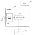
例えば、上記実施の形態1及びその変形例では、図3に示されたように、中継機器20は、ループアンテナ201と近接無線通信部204とコントローラ205とメモリ206と通信部207とを備えていることとした。しかし、図11に示すように、中継機器21は、少なくとも、ループアンテナ201と近接無線通信部204とコントローラ205とを備えていればよく、メモリ206と通信部207とは中継機器21の外部に備えられていてもよい。つまり、近接無線通信部204は、ループアンテナ201を介して端末機器10と近接無線通信を行い、端末機器10から受信する情報を処理するソフトウェアを識別するソフトウェア識別情報を端末機器10から受信し、コントローラ205は、外部のメモリ206または通信部207から、ソフトウェア識別情報に対応するソフトウェアを取得し、起動させることにしてもよい。 For example, in the first embodiment and the modification thereof, as illustrated in FIG. 3, the
また、本発明は、このような通信装置として実現できるだけでなく、当該通信装置を構成する各処理部を備える集積回路として実現したり、当該各処理部の処理をステップとする通信方法として実現したりすることができる。さらに、本発明は、それらステップをコンピュータに実行させるプログラムとして実現したり、そのプログラムを記録したコンピュータ読み取り可能なCD−ROMなどの記録媒体として実現したり、そのプログラムを示す情報、データまたは信号として実現したりすることもできる。そして、それらプログラム、情報、データ及び信号は、インターネット等の通信ネットワークを介して配信してもよい。 In addition, the present invention can be realized not only as such a communication device but also as an integrated circuit including each processing unit constituting the communication device, or as a communication method using the processing of each processing unit as a step. Can be. Furthermore, the present invention can be realized as a program for causing a computer to execute these steps, as a recording medium such as a computer-readable CD-ROM in which the program is recorded, or as information, data, or a signal indicating the program. It can also be realized. These programs, information, data, and signals may be distributed via a communication network such as the Internet.
本発明に係る通信装置は、近接無線機能を有し、例えば不具合に至った使用履歴情報を近接無線通信によって自動的に取得することで、故障時の不再現課題を解決するシステム等として有用である。 The communication device according to the present invention has a proximity wireless function, and is useful as a system that solves a non-reproduction problem at the time of failure by automatically acquiring, for example, usage history information that has led to a failure by proximity wireless communication. is there.
1 通信システム
10 端末機器
20、21 中継機器
30 ネットワーク
31 サーバ機器
101 コントローラ
102 メモリ
103 近接無線通信部
104 ループアンテナ
201 ループアンテナ
202 表示部
203 入力部
204 近接無線通信部
205 コントローラ
206 メモリ
207 通信部
1001 端末機器固有情報
1002 サーバアクセス情報
1003 アプリケーション識別情報
2011 中継機器識別情報(製造番号)
2012 使用者識別情報(SIMカードID等)
2013 中継機器型番(製造品番)
2014 アプリケーションソフト
2015 サーバアクセス情報
2016 サーバアドレス(URL)
5000 携帯機器
5001 端末部
5002 近接無線通信部
5010 システムコントローラ
5011 メモリ部
5012 アプリメモリ
5013 機器情報メモリ
5014 汎用メモリ
5015 アプリ管理部
5016 アプリインストール部
5017 アプリ判定部
5018 アプリ起動部
5019 通信部
5021 ループアンテナ
5022 近接通信制御部
5023 近接通信メモリ
5024 通信モード切替部
6000 端末通信情報
6001 端末情報
6002 ICタグ個別ID
6003 端末型番
6004 端末品番
6005 製造者ID
6006 製造年月日
6007 端末使用履歴情報
6008 端末不具合情報
6009 アプリアクセス情報
6010 アプリ識別情報
6011 アプリダウンロードURL
6012 アクセス情報
6013 登録データベースURL
6100 携帯通信情報
6101 端末情報
6109 通信機器情報
6110 通信機器ID
6111 位置情報(GPS)
6112 アプリバージョン
6113 利用者情報
6114 契約者ID
6115 電話番号
6116 メールアドレス
6117 サービスアカウントDESCRIPTION OF SYMBOLS 1
2012 User identification information (SIM card ID, etc.)
2013 Relay equipment model number (manufactured product number)
2014
5000
6003
6006 Date of
6012
6100
6111 Location information (GPS)
6112
6115
Claims (9)
Translated fromJapanese前記通信端末装置からの電波を受信するアンテナ部と、
前記アンテナ部を介して前記通信端末装置と近接無線通信を行い、前記通信端末装置から受信する情報を処理するソフトウェアを識別するソフトウェア識別情報を、前記通信端末装置から受信する近接無線通信部と、
受信された前記ソフトウェア識別情報に対応するソフトウェアである対応ソフトウェアを取得し、取得した前記対応ソフトウェアを起動させる制御部と
を備える通信装置。A communication device that performs proximity wireless communication with a communication terminal device and processes information received from the communication terminal device by software,
An antenna unit for receiving radio waves from the communication terminal device;
Proximity wireless communication with the communication terminal device via the antenna unit, software identification information for identifying software for processing information received from the communication terminal device, a proximity wireless communication unit that receives from the communication terminal device,
A communication apparatus comprising: a control unit that acquires corresponding software that is software corresponding to the received software identification information, and activates the acquired corresponding software.
1以上のソフトウェアを記憶している記憶部を備え、
前記制御部は、前記記憶部に前記対応ソフトウェアが記憶されている場合に、前記記憶部から前記対応ソフトウェアを取得し、取得した前記対応ソフトウェアを起動させる
請求項1に記載の通信装置。further,
A storage unit storing at least one software;
The communication device according to claim 1, wherein the control unit acquires the corresponding software from the storage unit and activates the acquired corresponding software when the corresponding software is stored in the storage unit.
前記通信装置は、さらに、
前記記憶装置と通信する通信部を備え、
前記制御部は、
前記ソフトウェア識別情報を用いて、前記記憶部に前記対応ソフトウェアが記憶されているか否かを判定し、
前記記憶部に前記対応ソフトウェアが記憶されていると判定した場合には、前記記憶部から前記対応ソフトウェアを取得し、取得した前記対応ソフトウェアを起動させ、
前記記憶部に前記対応ソフトウェアが記憶されていないと判定した場合には、前記通信部を介して、前記対応ソフトウェアを送信するよう依頼するソフトウェア送信依頼信号を前記記憶装置に送信することで前記記憶装置から前記対応ソフトウェアを取得し、取得した前記対応ソフトウェアを起動させる
請求項2に記載の通信装置。The communication device is connected via a communication network to a storage device storing one or more software including the corresponding software.
The communication device further includes:
A communication unit that communicates with the storage device;
The controller is
Using the software identification information, determine whether the corresponding software is stored in the storage unit,
When it is determined that the corresponding software is stored in the storage unit, the corresponding software is acquired from the storage unit, and the acquired corresponding software is activated,
If it is determined that the corresponding software is not stored in the storage unit, a software transmission request signal for requesting transmission of the corresponding software is transmitted to the storage device via the communication unit. The communication device according to claim 2, wherein the corresponding software is acquired from a device, and the acquired corresponding software is activated.
前記制御部は、前記記憶部に前記対応ソフトウェアが記憶されていないと判定した場合には、前記通信部を介して、受信された前記記憶装置識別情報で示される記憶装置に、前記ソフトウェア識別情報と前記通信装置を識別する通信装置識別情報とが含まれる前記ソフトウェア送信依頼信号を送信することで、前記記憶装置から前記対応ソフトウェアを取得し、取得した前記対応ソフトウェアを起動させる
請求項3に記載の通信装置。The proximity wireless communication unit further receives storage device identification information for identifying the storage device from the communication terminal device,
When the control unit determines that the corresponding software is not stored in the storage unit, the software identification information is stored in the storage device indicated by the received storage device identification information via the communication unit. 4. The corresponding software is acquired from the storage device by transmitting the software transmission request signal including communication device identification information for identifying the communication device, and the acquired corresponding software is activated. Communication equipment.
前記近接無線通信部は、前記通信端末装置から、前記登録装置を識別する登録装置識別情報と前記通信端末装置を識別する端末識別情報とをさらに受信し、
前記制御部は、前記通信端末装置から受信する情報の登録を行うための前記対応ソフトウェアを起動させることで、受信された前記端末識別情報を少なくとも含む情報を、前記通信装置を識別する通信装置識別情報に関連付けて、前記登録装置識別情報で示される登録装置に送信する
請求項1〜4のいずれか1項に記載の通信装置。The communication device is connected to a registration device for registering information via a communication network,
The proximity wireless communication unit further receives registration device identification information for identifying the registration device and terminal identification information for identifying the communication terminal device from the communication terminal device,
The control unit activates the corresponding software for registering information received from the communication terminal device, thereby identifying the communication device with information including at least the received terminal identification information. The communication apparatus according to any one of claims 1 to 4, wherein the communication apparatus transmits the information to a registration apparatus indicated by the registration apparatus identification information in association with information.
請求項1〜5のいずれか1項に記載の通信装置。The proximity wireless communication unit transmits a polling signal to the communication terminal device, and when the proximity wireless communication is established by receiving a polling response from the communication terminal device, transmits the software identification information to the communication terminal device. The communication device according to any one of claims 1 to 5, wherein the software identification information is received from the communication terminal device by making a request.
請求項1〜5のいずれか1項に記載の通信装置。The proximity wireless communication unit, when receiving a polling signal from the communication terminal device, establishes proximity wireless communication by transmitting a polling response to the communication terminal device, and receives the software identification information from the communication terminal device The communication device according to any one of claims 1 to 5.
前記通信モード切替部は、前記通信端末装置がリーダライタ機器の場合に、前記近接無線通信部をリーダライタモードに切り替え、前記通信端末装置がタグ機器の場合に、前記近接無線通信部をタグモードに切り替える
請求項1〜5のいずれか1項に記載の通信装置。The proximity wireless communication unit performs proximity wireless communication with a reader / writer mode in which the proximity wireless communication unit performs proximity wireless communication with a reader / writer device having a reader / writer function, and a proximity wireless communication with a tag device in which the proximity wireless communication unit has an IC tag function. A communication mode switching unit that switches between tag modes to be performed,
The communication mode switching unit switches the proximity wireless communication unit to a reader / writer mode when the communication terminal device is a reader / writer device, and sets the proximity wireless communication unit to a tag mode when the communication terminal device is a tag device. The communication apparatus according to any one of claims 1 to 5.
前記アンテナ部を介して前記通信端末装置と近接無線通信を行い、前記通信端末装置から受信する情報を処理するソフトウェアを識別するソフトウェア識別情報を、前記通信端末装置から受信する近接無線通信ステップと、
受信された前記ソフトウェア識別情報に対応するソフトウェアである対応ソフトウェアを取得し、取得した前記対応ソフトウェアを起動させる制御ステップと
を含む通信方法。A communication method for performing proximity wireless communication with a communication terminal device, and processing information received from the communication terminal device via an antenna by software,
Proximity wireless communication with the communication terminal device via the antenna unit, and receiving software identification information for identifying software for processing information received from the communication terminal device from the communication terminal device;
And a control step of acquiring corresponding software that is software corresponding to the received software identification information and starting the acquired corresponding software.
Applications Claiming Priority (3)
| Application Number | Priority Date | Filing Date | Title |
|---|---|---|---|
| JP2010158252 | 2010-07-12 | ||
| JP2010158252 | 2010-07-12 | ||
| PCT/JP2011/003759WO2012008108A1 (en) | 2010-07-12 | 2011-06-30 | Communication device and communication method |
Publications (1)
| Publication Number | Publication Date |
|---|---|
| JPWO2012008108A1true JPWO2012008108A1 (en) | 2013-09-05 |
Family
ID=45469128
Family Applications (1)
| Application Number | Title | Priority Date | Filing Date |
|---|---|---|---|
| JP2012524414APendingJPWO2012008108A1 (en) | 2010-07-12 | 2011-06-30 | Communication apparatus and communication method |
Country Status (5)
| Country | Link |
|---|---|
| US (1) | US8886124B2 (en) |
| EP (1) | EP2595364A1 (en) |
| JP (1) | JPWO2012008108A1 (en) |
| CN (1) | CN102484661A (en) |
| WO (1) | WO2012008108A1 (en) |
Families Citing this family (65)
| Publication number | Priority date | Publication date | Assignee | Title |
|---|---|---|---|---|
| US20070218837A1 (en)* | 2006-03-14 | 2007-09-20 | Sony Ericsson Mobile Communications Ab | Data communication in an electronic device |
| US10798540B2 (en)* | 2017-02-14 | 2020-10-06 | Panasonic Intellectual Property Management Co., Ltd. | Information apparatus, communication apparatus, and communication method for information apparatus |
| DE102011003920A1 (en)* | 2011-02-10 | 2012-08-16 | Siemens Aktiengesellschaft | Mobile radio operated electronic access system |
| US9727879B2 (en)* | 2011-03-30 | 2017-08-08 | Nokia Technologies Oy | Method and apparatus for providing tag-based content installation |
| US20130040561A1 (en)* | 2011-08-12 | 2013-02-14 | Ivo Conde e Silva | System and method for launching and/or downloading applications with near field communication tags |
| EP2590107B1 (en)* | 2011-11-03 | 2019-08-21 | STMicroelectronics Application GmbH | Method of managing incoming commands related to contactless applications within a wireless apparatus such as a NFC enabled mobile phone |
| US9143402B2 (en)* | 2012-02-24 | 2015-09-22 | Qualcomm Incorporated | Sensor based configuration and control of network devices |
| FR2987479A1 (en)* | 2012-02-29 | 2013-08-30 | Nghia Phan | METHOD AND DEVICE FOR IDENTIFYING COMMUNICABLE PORTABLE ELECTRONIC DEVICES. |
| JP6019676B2 (en) | 2012-03-30 | 2016-11-02 | ブラザー工業株式会社 | Communication device |
| JP6019675B2 (en) | 2012-03-30 | 2016-11-02 | ブラザー工業株式会社 | Function execution device |
| US20130316645A1 (en)* | 2012-05-23 | 2013-11-28 | Health & Life Co., Ltd. | Near field communication enabled medical device system |
| JP5867319B2 (en) | 2012-07-03 | 2016-02-24 | ブラザー工業株式会社 | Communication device |
| WO2014007710A1 (en)* | 2012-07-06 | 2014-01-09 | Telefonaktiebolaget L M Ericsson (Publ) | Data transfer using near field communications |
| JP5900228B2 (en)* | 2012-08-06 | 2016-04-06 | ブラザー工業株式会社 | Communication device |
| JP6056002B2 (en)* | 2012-08-08 | 2017-01-11 | パナソニックIpマネジメント株式会社 | Washing machine communication system |
| KR101974820B1 (en)* | 2012-09-10 | 2019-08-23 | 삼성전자주식회사 | Method for controlling a device and device performing the same |
| JP6015265B2 (en)* | 2012-09-13 | 2016-10-26 | ヤマハ株式会社 | Proximity communication system |
| TWI502887B (en)* | 2012-09-27 | 2015-10-01 | Hon Hai Prec Ind Co Ltd | Power source control device and control method |
| WO2014097755A1 (en)* | 2012-12-20 | 2014-06-26 | ソニー株式会社 | Communication device, communication method, communication system, and computer program |
| KR102050815B1 (en)* | 2013-01-07 | 2020-01-08 | 삼성전자주식회사 | Apparatus and method for providing a function of a near field communication in a poratable terminal |
| JP6164857B2 (en) | 2013-02-12 | 2017-07-19 | キヤノン株式会社 | Power feeding device, power feeding device control method, power receiving device, power receiving device control method, program |
| JP6265606B2 (en)* | 2013-02-22 | 2018-01-24 | キヤノン株式会社 | Printing apparatus, control method therefor, and program |
| JP5838987B2 (en) | 2013-03-28 | 2016-01-06 | ブラザー工業株式会社 | Communication device |
| KR102077824B1 (en)* | 2013-06-03 | 2020-02-14 | 휴렛-팩커드 디벨롭먼트 컴퍼니, 엘.피. | Method and Apparatus for image forming using near field communication |
| WO2014204369A1 (en)* | 2013-06-20 | 2014-12-24 | Telefonaktiebolaget L M Ericsson (Publ) | Electronic device, grid of communication points and methods for providing assistance to an electronic device |
| JP6128986B2 (en)* | 2013-06-24 | 2017-05-17 | 任天堂株式会社 | COMMUNICATION SYSTEM, COMMUNICATION TERMINAL DEVICE, COMMUNICATION PROGRAM, AND COMMUNICATION METHOD |
| US9824545B2 (en)* | 2013-06-28 | 2017-11-21 | Ncr Corporation | Information provision |
| US20150061836A1 (en)* | 2013-09-03 | 2015-03-05 | Adam Eikman | Assignable switch for portable devices |
| CN105556492B (en) | 2013-09-11 | 2018-07-17 | 惠普发展公司,有限责任合伙企业 | Near-field communication(NFC)Data transmission |
| WO2015037422A1 (en)* | 2013-09-11 | 2015-03-19 | 株式会社リコー | Wireless communication apparatus and portable apparatus |
| JP6264815B2 (en) | 2013-09-30 | 2018-01-24 | ブラザー工業株式会社 | Communication device |
| JP6338494B2 (en)* | 2013-11-28 | 2018-06-06 | パナソニック インテレクチュアル プロパティ コーポレーション オブ アメリカPanasonic Intellectual Property Corporation of America | Control method, program, program providing method, communication terminal, and control system |
| US20150162956A1 (en)* | 2013-12-06 | 2015-06-11 | Raveeshkumar Bhat | Near field communication based data transfer |
| CN103716070B (en)* | 2013-12-27 | 2016-07-06 | 深圳市国华光电科技有限公司 | A kind of method of outputting alarm prompt, device, equipment and system |
| CN203933626U (en)* | 2014-01-29 | 2014-11-05 | 上海诺司纬光电仪器有限公司 | The wireless control system of the leveling instrument |
| US9444518B2 (en)* | 2014-01-31 | 2016-09-13 | Sony Corporation | One touch product information on mobile communication device using near field communication |
| US10846749B1 (en) | 2014-03-12 | 2020-11-24 | Groupon, Inc. | Method and system for offering promotion impressions using application programs |
| US10891651B1 (en)* | 2014-03-12 | 2021-01-12 | Groupon, Inc. | Method and system for launching application programs using promotion impressions |
| US10269043B1 (en) | 2014-03-12 | 2019-04-23 | Groupon, Inc. | Method and system for distribution of application program for promotion and marketing service |
| US10937062B1 (en)* | 2014-03-12 | 2021-03-02 | Groupon, Inc. | Method and system for facilitating download of application programs on mobile computing device |
| US11010793B1 (en)* | 2014-03-12 | 2021-05-18 | Groupon, Inc. | Method and system for determining user profile data for promotion and marketing service using mobile application program information |
| US11042904B1 (en)* | 2014-03-12 | 2021-06-22 | Groupon, Inc. | Method and system for detecting application programs on mobile computing device |
| US20150280786A1 (en)* | 2014-03-31 | 2015-10-01 | Raveeshkumar Bhat | Near field communication based data transfer |
| JP2015200974A (en)* | 2014-04-04 | 2015-11-12 | 敬治 姫野 | emergency contact system |
| JP6402494B2 (en) | 2014-05-30 | 2018-10-10 | ブラザー工業株式会社 | Function execution system, function execution device, and communication terminal |
| JP2016010117A (en)* | 2014-06-26 | 2016-01-18 | カシオ計算機株式会社 | Wireless communication apparatus, wireless communication system, wireless communication method, and program |
| CN105376138B (en)* | 2014-08-28 | 2019-11-19 | 腾讯科技(深圳)有限公司 | Method for adding contacts, method for data transmission, and user equipment |
| EP3018913B1 (en)* | 2014-11-10 | 2018-10-03 | Nxp B.V. | Media player |
| US9438317B2 (en)* | 2014-12-19 | 2016-09-06 | Intel Corporation | Card detect architecture for near field communications |
| WO2016139865A1 (en)* | 2015-03-02 | 2016-09-09 | 京セラドキュメントソリューションズ株式会社 | Communication system, communication method, and image forming device |
| US9445396B1 (en)* | 2015-03-13 | 2016-09-13 | Toshiba Global Commerce Solutions Holdings Corporation | Signage acknowledgement tied to personal computer device |
| JP6394449B2 (en)* | 2015-03-17 | 2018-09-26 | セイコーエプソン株式会社 | Device control apparatus, communication system, and device control apparatus control method |
| US10525342B2 (en)* | 2015-05-21 | 2020-01-07 | Sharp Kabushiki Kaisha | Information processing device and recording medium |
| JP6052438B2 (en)* | 2016-01-06 | 2016-12-27 | ブラザー工業株式会社 | Communication device |
| JP6168201B2 (en)* | 2016-06-23 | 2017-07-26 | ブラザー工業株式会社 | Communication device |
| CN107809755A (en)* | 2016-09-06 | 2018-03-16 | 中兴通讯股份有限公司 | Terminal control method and device |
| WO2018198748A1 (en)* | 2017-04-26 | 2018-11-01 | サトーホールディングス株式会社 | Communication method and packing box |
| US10547996B2 (en)* | 2017-09-25 | 2020-01-28 | Kabushiki Kaisha Toshiba | Information processing apparatus, storage medium, and information processing method |
| JP6508291B2 (en)* | 2017-11-01 | 2019-05-08 | ブラザー工業株式会社 | Communication device |
| CN107659921B (en)* | 2017-11-08 | 2023-12-26 | 上海坤锐电子科技有限公司 | NFC universal realization circuit and chip |
| CN110099403B (en)* | 2019-05-17 | 2022-07-19 | 腾讯科技(深圳)有限公司 | A data transmission method, device, equipment and storage medium |
| US11026051B2 (en)* | 2019-07-29 | 2021-06-01 | Apple Inc. | Wireless communication modes based on mobile device orientation |
| EP3859526A1 (en)* | 2020-01-30 | 2021-08-04 | Hewlett-Packard Development Company, L.P. | Error information storage |
| JP7411960B2 (en)* | 2020-03-25 | 2024-01-12 | パナソニックIpマネジメント株式会社 | Control device, control system, control method, and program |
| CN117395639B (en)* | 2023-12-12 | 2024-05-14 | 荣耀终端有限公司 | Device search method and electronic device |
Citations (4)
| Publication number | Priority date | Publication date | Assignee | Title |
|---|---|---|---|---|
| JP2004030168A (en)* | 2002-06-25 | 2004-01-29 | Aruze Corp | Member registration method and member registration system |
| JP2006505182A (en)* | 2002-11-01 | 2006-02-09 | ノキア コーポレイション | Disposable mini application |
| JP2006191540A (en)* | 2004-12-09 | 2006-07-20 | Ntt Docomo Inc | Service providing system, portable terminal and portable terminal control program |
| JP2010066928A (en)* | 2008-09-09 | 2010-03-25 | Olympus Corp | Server system, electronic equipment, communication terminal, and authentication method |
Family Cites Families (8)
| Publication number | Priority date | Publication date | Assignee | Title |
|---|---|---|---|---|
| JP2003234840A (en)* | 2002-02-12 | 2003-08-22 | Seiko Epson Corp | Communication support device, communication support program, and communication support method |
| JP4162464B2 (en) | 2002-10-22 | 2008-10-08 | 大日本印刷株式会社 | Non-contact IC tag distribution device and non-contact IC tag distribution method |
| US8376216B2 (en)* | 2005-02-25 | 2013-02-19 | Kyocera Corporation | Reader device with reading time counting unit |
| JP4562550B2 (en)* | 2005-02-25 | 2010-10-13 | 京セラ株式会社 | IDENTIFICATION INFORMATION READING DEVICE AND INFORMATION PROVIDING SYSTEM |
| JP2009087314A (en) | 2007-09-14 | 2009-04-23 | Soriton Syst:Kk | Customer management support system |
| EP2106107B1 (en)* | 2008-03-27 | 2012-04-18 | Motorola Mobility, Inc. | Method and apparatus for automatic near field communication application selection in an electronic device |
| WO2010036017A2 (en)* | 2008-09-24 | 2010-04-01 | Lg Electronics Inc. | Method and apparatus for communicating with external device using contactless interface |
| US8060627B2 (en)* | 2008-09-30 | 2011-11-15 | Apple Inc. | Device-to-device workflows |
- 2011
- 2011-06-30JPJP2012524414Apatent/JPWO2012008108A1/enactivePending
- 2011-06-30WOPCT/JP2011/003759patent/WO2012008108A1/enactiveApplication Filing
- 2011-06-30USUS13/395,132patent/US8886124B2/enactiveActive
- 2011-06-30EPEP11806445.0Apatent/EP2595364A1/ennot_activeWithdrawn
- 2011-06-30CNCN2011800037602Apatent/CN102484661A/enactivePending
Patent Citations (4)
| Publication number | Priority date | Publication date | Assignee | Title |
|---|---|---|---|---|
| JP2004030168A (en)* | 2002-06-25 | 2004-01-29 | Aruze Corp | Member registration method and member registration system |
| JP2006505182A (en)* | 2002-11-01 | 2006-02-09 | ノキア コーポレイション | Disposable mini application |
| JP2006191540A (en)* | 2004-12-09 | 2006-07-20 | Ntt Docomo Inc | Service providing system, portable terminal and portable terminal control program |
| JP2010066928A (en)* | 2008-09-09 | 2010-03-25 | Olympus Corp | Server system, electronic equipment, communication terminal, and authentication method |
Also Published As
| Publication number | Publication date |
|---|---|
| WO2012008108A1 (en) | 2012-01-19 |
| CN102484661A (en) | 2012-05-30 |
| US8886124B2 (en) | 2014-11-11 |
| US20120171952A1 (en) | 2012-07-05 |
| EP2595364A1 (en) | 2013-05-22 |
Similar Documents
| Publication | Publication Date | Title |
|---|---|---|
| JPWO2012008108A1 (en) | Communication apparatus and communication method | |
| CN102742256B (en) | Communicator, communication means and communication system | |
| EP3716656B1 (en) | Profile generation method, profile acquisition method, and related device and storage medium | |
| US8855563B2 (en) | Communication apparatus and communication method | |
| US8811897B2 (en) | Near field communication device and method of controlling the same | |
| EP3794431B1 (en) | Electronic device including electronic pen and method of controlling communication connection between electronic device and electronic pen | |
| US11395132B2 (en) | Method for transferring subscription and electronic device for supporting the same | |
| US11283909B2 (en) | Electronic device supporting multiple SIMs and operation method thereof | |
| CN109634990B (en) | Information processing method and system, electronic device, computer-readable storage medium | |
| CN104185980A (en) | Information processing device, wireless communication device, and communication system | |
| KR20190066989A (en) | Electronic device transmitting data obtained from an external device based on identification information of a cover device to the cover device and control method thereof | |
| US20150142937A1 (en) | Method and system for remote equipment data installation | |
| US12355877B2 (en) | Method for signing key management by electronic device, and electronic device therefor | |
| US10772157B2 (en) | Method for performing relay communication and electronic device thereof | |
| JP5724701B2 (en) | IC chip, processing method in IC chip, IC chip processing program, and portable terminal | |
| KR20140142996A (en) | Method for processing data of applet included in a plurity of secure element and apparatus for the same | |
| KR20210127503A (en) | Low power rcs communication electronic device and method thereof | |
| JP2007251275A (en) | Mobile phone and communication terminal |
Legal Events
| Date | Code | Title | Description |
|---|---|---|---|
| A621 | Written request for application examination | Free format text:JAPANESE INTERMEDIATE CODE: A621 Effective date:20140415 | |
| A711 | Notification of change in applicant | Free format text:JAPANESE INTERMEDIATE CODE: A711 Effective date:20140606 | |
| A131 | Notification of reasons for refusal | Free format text:JAPANESE INTERMEDIATE CODE: A131 Effective date:20150901 | |
| A521 | Request for written amendment filed | Free format text:JAPANESE INTERMEDIATE CODE: A523 Effective date:20151008 | |
| A02 | Decision of refusal | Free format text:JAPANESE INTERMEDIATE CODE: A02 Effective date:20160510 |