JPWO2011036700A1 - Exhaust pipe parts and exhaust system for internal combustion engine - Google Patents
Exhaust pipe parts and exhaust system for internal combustion engineDownload PDFInfo
- Publication number
- JPWO2011036700A1 JPWO2011036700A1JP2011532785AJP2011532785AJPWO2011036700A1JP WO2011036700 A1JPWO2011036700 A1JP WO2011036700A1JP 2011532785 AJP2011532785 AJP 2011532785AJP 2011532785 AJP2011532785 AJP 2011532785AJP WO2011036700 A1JPWO2011036700 A1JP WO2011036700A1
- Authority
- JP
- Japan
- Prior art keywords
- pipe
- exhaust
- tail pipe
- short
- exhaust pipe
- Prior art date
- Legal status (The legal status is an assumption and is not a legal conclusion. Google has not performed a legal analysis and makes no representation as to the accuracy of the status listed.)
- Granted
Links
Images


Classifications
- F—MECHANICAL ENGINEERING; LIGHTING; HEATING; WEAPONS; BLASTING
- F01—MACHINES OR ENGINES IN GENERAL; ENGINE PLANTS IN GENERAL; STEAM ENGINES
- F01N—GAS-FLOW SILENCERS OR EXHAUST APPARATUS FOR MACHINES OR ENGINES IN GENERAL; GAS-FLOW SILENCERS OR EXHAUST APPARATUS FOR INTERNAL-COMBUSTION ENGINES
- F01N13/00—Exhaust or silencing apparatus characterised by constructional features
- F01N13/02—Exhaust or silencing apparatus characterised by constructional features having two or more separate silencers in series
- F—MECHANICAL ENGINEERING; LIGHTING; HEATING; WEAPONS; BLASTING
- F01—MACHINES OR ENGINES IN GENERAL; ENGINE PLANTS IN GENERAL; STEAM ENGINES
- F01N—GAS-FLOW SILENCERS OR EXHAUST APPARATUS FOR MACHINES OR ENGINES IN GENERAL; GAS-FLOW SILENCERS OR EXHAUST APPARATUS FOR INTERNAL-COMBUSTION ENGINES
- F01N1/00—Silencing apparatus characterised by method of silencing
- F01N1/02—Silencing apparatus characterised by method of silencing by using resonance
- F01N1/023—Helmholtz resonators
- F—MECHANICAL ENGINEERING; LIGHTING; HEATING; WEAPONS; BLASTING
- F01—MACHINES OR ENGINES IN GENERAL; ENGINE PLANTS IN GENERAL; STEAM ENGINES
- F01N—GAS-FLOW SILENCERS OR EXHAUST APPARATUS FOR MACHINES OR ENGINES IN GENERAL; GAS-FLOW SILENCERS OR EXHAUST APPARATUS FOR INTERNAL-COMBUSTION ENGINES
- F01N1/00—Silencing apparatus characterised by method of silencing
- F01N1/06—Silencing apparatus characterised by method of silencing by using interference effect
- F—MECHANICAL ENGINEERING; LIGHTING; HEATING; WEAPONS; BLASTING
- F01—MACHINES OR ENGINES IN GENERAL; ENGINE PLANTS IN GENERAL; STEAM ENGINES
- F01N—GAS-FLOW SILENCERS OR EXHAUST APPARATUS FOR MACHINES OR ENGINES IN GENERAL; GAS-FLOW SILENCERS OR EXHAUST APPARATUS FOR INTERNAL-COMBUSTION ENGINES
- F01N1/00—Silencing apparatus characterised by method of silencing
- F01N1/08—Silencing apparatus characterised by method of silencing by reducing exhaust energy by throttling or whirling
- F—MECHANICAL ENGINEERING; LIGHTING; HEATING; WEAPONS; BLASTING
- F01—MACHINES OR ENGINES IN GENERAL; ENGINE PLANTS IN GENERAL; STEAM ENGINES
- F01N—GAS-FLOW SILENCERS OR EXHAUST APPARATUS FOR MACHINES OR ENGINES IN GENERAL; GAS-FLOW SILENCERS OR EXHAUST APPARATUS FOR INTERNAL-COMBUSTION ENGINES
- F01N1/00—Silencing apparatus characterised by method of silencing
- F01N1/16—Silencing apparatus characterised by method of silencing by using movable parts
- F01N1/161—Silencing apparatus characterised by method of silencing by using movable parts for adjusting resonance or dead chambers or passages to resonance or dead chambers
- F01N1/163—Silencing apparatus characterised by method of silencing by using movable parts for adjusting resonance or dead chambers or passages to resonance or dead chambers by means of valves
- F—MECHANICAL ENGINEERING; LIGHTING; HEATING; WEAPONS; BLASTING
- F01—MACHINES OR ENGINES IN GENERAL; ENGINE PLANTS IN GENERAL; STEAM ENGINES
- F01N—GAS-FLOW SILENCERS OR EXHAUST APPARATUS FOR MACHINES OR ENGINES IN GENERAL; GAS-FLOW SILENCERS OR EXHAUST APPARATUS FOR INTERNAL-COMBUSTION ENGINES
- F01N1/00—Silencing apparatus characterised by method of silencing
- F01N1/16—Silencing apparatus characterised by method of silencing by using movable parts
- F01N1/166—Silencing apparatus characterised by method of silencing by using movable parts for changing the flow path through the silencer or for adjusting the dimensions of a chamber or a pipe
- F—MECHANICAL ENGINEERING; LIGHTING; HEATING; WEAPONS; BLASTING
- F01—MACHINES OR ENGINES IN GENERAL; ENGINE PLANTS IN GENERAL; STEAM ENGINES
- F01N—GAS-FLOW SILENCERS OR EXHAUST APPARATUS FOR MACHINES OR ENGINES IN GENERAL; GAS-FLOW SILENCERS OR EXHAUST APPARATUS FOR INTERNAL-COMBUSTION ENGINES
- F01N13/00—Exhaust or silencing apparatus characterised by constructional features
- F01N13/08—Other arrangements or adaptations of exhaust conduits
- F01N13/082—Other arrangements or adaptations of exhaust conduits of tailpipe, e.g. with means for mixing air with exhaust for exhaust cooling, dilution or evacuation
- F—MECHANICAL ENGINEERING; LIGHTING; HEATING; WEAPONS; BLASTING
- F01—MACHINES OR ENGINES IN GENERAL; ENGINE PLANTS IN GENERAL; STEAM ENGINES
- F01N—GAS-FLOW SILENCERS OR EXHAUST APPARATUS FOR MACHINES OR ENGINES IN GENERAL; GAS-FLOW SILENCERS OR EXHAUST APPARATUS FOR INTERNAL-COMBUSTION ENGINES
- F01N2210/00—Combination of methods of silencing
- F01N2210/02—Resonance and interference
- F—MECHANICAL ENGINEERING; LIGHTING; HEATING; WEAPONS; BLASTING
- F01—MACHINES OR ENGINES IN GENERAL; ENGINE PLANTS IN GENERAL; STEAM ENGINES
- F01N—GAS-FLOW SILENCERS OR EXHAUST APPARATUS FOR MACHINES OR ENGINES IN GENERAL; GAS-FLOW SILENCERS OR EXHAUST APPARATUS FOR INTERNAL-COMBUSTION ENGINES
- F01N2470/00—Structure or shape of exhaust gas passages, pipes or tubes
- F01N2470/20—Dimensional characteristics of tubes, e.g. length, diameter
- F—MECHANICAL ENGINEERING; LIGHTING; HEATING; WEAPONS; BLASTING
- F01—MACHINES OR ENGINES IN GENERAL; ENGINE PLANTS IN GENERAL; STEAM ENGINES
- F01N—GAS-FLOW SILENCERS OR EXHAUST APPARATUS FOR MACHINES OR ENGINES IN GENERAL; GAS-FLOW SILENCERS OR EXHAUST APPARATUS FOR INTERNAL-COMBUSTION ENGINES
- F01N2470/00—Structure or shape of exhaust gas passages, pipes or tubes
- F01N2470/24—Concentric tubes or tubes being concentric to housing, e.g. telescopically assembled
Landscapes
- Engineering & Computer Science (AREA)
- Chemical & Material Sciences (AREA)
- Combustion & Propulsion (AREA)
- Mechanical Engineering (AREA)
- General Engineering & Computer Science (AREA)
- Exhaust Silencers (AREA)
Abstract
Translated fromJapaneseDescription
Translated fromJapanese本発明は、排気管部品および内燃機関の排気装置に関し、特に、排気ガスの排気方向の最下流に設けられた排気管の気柱共鳴による排気騒音を低減するようにした排気管部品および内燃機関の排気装置に関する。 The present invention relates to an exhaust pipe part and an exhaust device for an internal combustion engine, and more particularly to an exhaust pipe part and an internal combustion engine that reduce exhaust noise due to air column resonance in an exhaust pipe provided at the most downstream in the exhaust direction of exhaust gas. The present invention relates to an exhaust device.
自動車等の車両に用いられる内燃機関の排気装置としては、図32に示すようなものが知られている(例えば、特許文献1参照)。図32において、内燃機関としてのエンジン1から排気マニホールド2に排気される排気ガスは、触媒コンバータ3によって浄化された後に、排気装置4に導入される。 As an exhaust device for an internal combustion engine used in a vehicle such as an automobile, one as shown in FIG. 32 is known (see, for example, Patent Document 1). In FIG. 32, exhaust gas exhausted from the
排気装置4は、触媒コンバータ3に連結されたフロントパイプ5、フロントパイプ5に連結されたセンターパイプ6、センターパイプ6に連結された消音器としてのメインマフラ7、メインマフラ7に連結されたテールパイプ8およびテールパイプ8に介装されたサブマフラ9から構成されている。 The exhaust device 4 includes a
メインマフラ7は、内部に排気ガスを拡張して消音するための拡張室と、ヘルムホルツ共鳴によって特定の周波数の排気音を消音するための共鳴室とが設けられている。具体的には、共鳴室は、共鳴室の容積を大きくしたり、共鳴室内に突出するセンターパイプ6の突出長さを長くすることにより、共鳴周波数を低周波数側にチューニングすることができるとともに、共鳴室の容積を小さくしたり、共鳴室内に突出するセンターパイプ6の突出部分の長さを短くすることにより、共鳴周波数を高周波数側にチューニングすることができるようになっている。 The
サブマフラ9は、エンジン1の運転時の排気脈動によってテールパイプ8内でテールパイプ8の管長に対応した気柱共鳴が発生したときに、この気柱共鳴の音圧レベルを低減するようになっている。 When the air column resonance corresponding to the length of the
一般に、排気ガスの排気方向上流側および下流側にそれぞれ上流開口端および下流開口端を有するパイプは、エンジンの運転時の排気脈動による入射波がパイプの上流開口端および下流開口端で反射することにより、パイプの管長を半波長とした周波数の気柱共鳴を基本成分として、その半波長の自然数倍の波長の気柱共鳴が発生する。 In general, in a pipe having an upstream opening end and a downstream opening end on the upstream side and downstream side of the exhaust gas in the exhaust direction, incident waves due to exhaust pulsation during engine operation are reflected at the upstream opening end and the downstream opening end of the pipe. Thus, air column resonance having a wavelength that is a natural number multiple of the half wavelength is generated with air column resonance having a frequency with the pipe length of the half wavelength as a basic component.
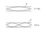
例えば、サブマフラ9が設けられていないテールパイプ8がメインマフラ7から後方に延在している場合を例にすると、図33に示すように、基本振動(一次成分)の気柱共鳴の波長λ1は、テールパイプ8の管長Lの略2倍となり、二次成分の気柱共鳴の波長λ2は、管長Lの略1倍となる。このように、テールパイプ8内には上流開口端8aおよび下流開口端8bが定在波の音圧分布の節となるような定在波ができる。 For example, in the case where the
また、テールパイプ8の気柱共鳴周波数fmは、下記の式(1)で表される。 The air column resonance frequency fm of the
fm=(c/2L)・m............(1)
但し、c:音速、L:テールパイプの管長、m:次数
上記の式(1)から明らかなように、テールパイプ8の管長Lが長い程、気柱共鳴周波数fmがエンジン1の回転数が低い低周波数領域に移行してしまうことが知られている。
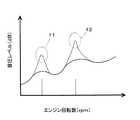
また、図34に示すように、エンジン1の排気脈動の周波数は、エンジン1の回転数が増大するのに伴って増大するようになっており、エンジン1の回転数に対応した気柱共鳴による排気音の一次成分f1と二次成分f2とで排気音の音圧レベル(dB)が高くなることが知られている。fm = (c / 2L) · m (1)
However, c: sound velocity, L: length of tail pipe, m: order As is clear from the above formula (1), the longer the pipe length L of the
Further, as shown in FIG. 34, the frequency of the exhaust pulsation of the
したがって、管長が長いテールパイプ8(例えば、テールパイプ8の管長が1.5m以上)を用いる場合には、エンジン回転数が低い常用回転域(2000rpm〜5000rpm)で気柱共鳴が発生してしまうことがあり、排気騒音が悪化してしまい、運転者に不快感を与えてしまうことになる。 Therefore, when the
特に、図32に示すように、気柱共鳴の一次成分f1の音圧のピーク(音圧分布の腹の幅)は、二次成分f2の音圧のピークよりも大きいため、常用回転域でこもり音と呼ばれる不快な騒音が発生してしまい、排気騒音の悪化の原因となる。 In particular, as shown in FIG. 32, since the peak of the sound pressure of the primary component f1 of the air column resonance (the antinode width of the sound pressure distribution) is larger than the peak of the sound pressure of the secondary component f2, An unpleasant noise called a booming noise is generated, which causes the exhaust noise to deteriorate.
このため、テールパイプ8の管長が長い場合には、図32に示す音圧レベルが高い定在波の腹の部分で、かつ、気柱共鳴による排気音の一次成分f1、二次成分f2のそれぞれの腹に対して最適な位置に、メインマフラ7より容量の小さなサブマフラ9を設けることにより、エンジン1の常用回転域において排気騒音を低減して、運転者に不快感を与えてしまうのを防止するようにしている。 Therefore, when the pipe length of the
しかしながら、このような従来のエンジン1の排気装置にあっては、気柱共鳴の音圧レベルを低減するために、テールパイプ8のサブマフラ9を設ける必要があるため、サブマフラ9を設ける分だけ排気装置4の重量が増大してしまうとともに、排気装置4の製造コストが増大してしまう。 However, in such an exhaust system of the
また、サブマフラ9を廃止して、テールパイプ8の気柱共鳴をメインマフラ7の共鳴室によって低減した場合に、共鳴室の容積を大きくする必要があるため、メインマフラ7が大型化してしまい、メインマフラ7の大型化に伴って排気装置4の重量が増大してしまうとともに、排気装置4の製造コストが増大してしまう。 Further, when the
本発明は、上述のような従来の問題を解決するためになされたもので、従来用いられていたマフラを廃止するとともに排気管の一端部に設けられた消音器を小型化して排気騒音を低減することができ、排気装置の重量を低減することができるとともに、排気装置の製造コストを低減することができる排気管部品および内燃機関の排気装置を提供することを目的とする。 The present invention has been made to solve the above-described conventional problems. The muffler used in the past is eliminated, and the silencer provided at one end of the exhaust pipe is miniaturized to reduce exhaust noise. An object of the present invention is to provide an exhaust pipe component and an exhaust device for an internal combustion engine that can reduce the weight of the exhaust device and reduce the manufacturing cost of the exhaust device.
本発明に係る排気管部品は、上記目的を達成するため、(1)一端部に内燃機関から排出された排気ガスの排気方向上流側の消音器に接続される上流開口端を有するとともに、他端部に排気ガスを大気に排出するための下流開口端を有する排気管に取付けられ、前記排気管の一部を構成する排気管部品であって、前記排気管内に生じる気柱共鳴の音圧分布の節を含んだ領域に位置するようにして前記排気管の軸線方向に連接される中空部材と、前記中空部材の内部に設けられ、前記排気管の軸線方向に沿って所定長延在する短管とを備え、前記短管は、軸線方向一端に閉口端を有するとともに軸線方向他端に開口端を有し、前記閉口端が前記排気管内で発生する気柱共鳴の定在波の音圧分布の節と略同位置に位置するものから構成されている。 In order to achieve the above object, an exhaust pipe component according to the present invention has (1) an upstream opening end connected to a silencer on the upstream side in the exhaust direction of exhaust gas exhausted from an internal combustion engine at one end. An exhaust pipe component which is attached to an exhaust pipe having a downstream opening end for discharging exhaust gas to the atmosphere at an end and forms a part of the exhaust pipe, and which generates sound pressure of air column resonance generated in the exhaust pipe A hollow member connected in the axial direction of the exhaust pipe so as to be located in a region including the distribution nodes, and a short member provided inside the hollow member and extending a predetermined length along the axial direction of the exhaust pipe The short pipe has a closed end at one end in the axial direction and an open end at the other end in the axial direction, and the closed end has a sound pressure of standing wave of air column resonance generated in the exhaust pipe. Consists of those located approximately the same as the distribution nodes
この構成により、排気管部品を備えた排気管は、気柱共鳴の発生時に、音圧分布の節の位置において、排気管内の気柱共鳴が有するポテンシャルエネルギーを短管内に蓄積して排気管内のポテンシャルエネルギーを短管内と短管を除いた排気管内に分散することができる。
すなわち、気柱共鳴が発生する系が有する力学的エネルギーは、運動エネルギーとポテンシャルエネルギーの和で表され、力学的エネルギーは、保存される。With this configuration, the exhaust pipe having the exhaust pipe components accumulates the potential energy of the air column resonance in the exhaust pipe in the position of the sound pressure distribution at the position of the sound pressure distribution at the time of occurrence of the air column resonance. Potential energy can be dispersed in the short pipe and in the exhaust pipe excluding the short pipe.
That is, the mechanical energy possessed by the system in which air column resonance occurs is represented by the sum of kinetic energy and potential energy, and the mechanical energy is preserved.
音圧分布の節の位置は、音圧が最小となる反面、粒子速度が最大となるので、排気管内の気柱共鳴が有するポテンシャルエネルギーは、音圧が低い位置に設けられた短管内に蓄積され、このポテンシャルエネルギーは、外部に放出されない。 The position of the nodes in the sound pressure distribution minimizes the sound pressure, but maximizes the particle velocity, so the potential energy of the air column resonance in the exhaust pipe accumulates in the short pipe provided at the position where the sound pressure is low. This potential energy is not released to the outside.
このため、排気管内のポテンシャルエネルギーを、短管内のポテンシャルエネルギーと、短管を除いた排気管内のポテンシャルエネルギーとに分散して、短管を除いた排気管内のポテンシャルエネルギーのみを外部に放出することができる。このため、音圧のピークを下げて音圧レベルを低減することができ、排気騒音を低減することができる。 Therefore, the potential energy in the exhaust pipe is dispersed into the potential energy in the short pipe and the potential energy in the exhaust pipe excluding the short pipe, and only the potential energy in the exhaust pipe excluding the short pipe is released to the outside. Can do. For this reason, the sound pressure level can be reduced by lowering the peak of the sound pressure, and the exhaust noise can be reduced.
一方、中空部材の内部に、排気管の軸線方向に沿って所定長延在する短管が設けられるので、中空部材の内部の排気通路を絞るようにした場合に、気柱共鳴の定在波の粒子速度が最大となる音圧分布の節の位置において、粒子速度を上昇させることができる。 On the other hand, since a short pipe extending a predetermined length along the axial direction of the exhaust pipe is provided inside the hollow member, when the exhaust passage inside the hollow member is restricted, the standing wave of air column resonance The particle velocity can be increased at the node of the sound pressure distribution where the particle velocity is maximum.
排気管内の気柱共鳴が持つポテンシャルエネルギーは、排気管内のポテンシャルエネルギーと短管内のポテンシャルエネルギーに分散されているが、ポテンシャルエネルギーは、全体として変化がないのに対して、運動エネルギーを飛躍的に増大させることができるため、力学的エネルギーを増加させることができる。このため、排気管を擬似的に長くすることができ、気柱共鳴周波数を管長が長い排気管と同等の気柱共鳴周波数に下げることができる。 The potential energy of the air column resonance in the exhaust pipe is distributed between the potential energy in the exhaust pipe and the potential energy in the short pipe, but the potential energy does not change as a whole, while the kinetic energy is dramatically increased. Since it can be increased, the mechanical energy can be increased. For this reason, the exhaust pipe can be made pseudo-long, and the air column resonance frequency can be lowered to an air column resonance frequency equivalent to that of the exhaust pipe having a long tube length.
また、排気管が擬似的に長くなると、短管の内部に蓄積していたポテンシャルエネルギーを除いた排気管内のポテンシャルエネルギーは、排気管の伸び代分だけ排気管全体に分散されるため、力学的エネルギーの観点からは、排気管の内径が細くなったものと等価となり、気柱共鳴の音圧のピークをさらに低減して気柱共鳴の音圧レベルをさらに低減することができる。 In addition, when the exhaust pipe becomes pseudo-long, the potential energy in the exhaust pipe, excluding the potential energy accumulated inside the short pipe, is dispersed throughout the exhaust pipe by the amount of expansion of the exhaust pipe. From an energy point of view, this is equivalent to a case where the inner diameter of the exhaust pipe is reduced, and the sound pressure level of the air column resonance can be further reduced by further reducing the sound pressure peak of the air column resonance.
この結果、排気騒音を大幅に低減することができ、排気管部品を排気管と消音器とを備えた排気装置に設けた場合に、従来用いられていたマフラを廃止するとともに排気管の一端部に設けられた消音器を小型化して排気騒音を低減することができ、排気装置の重量を低減することができるとともに、排気装置の製造コストを低減することができる。 As a result, exhaust noise can be greatly reduced, and when an exhaust pipe component is provided in an exhaust system equipped with an exhaust pipe and a silencer, the conventionally used muffler is eliminated and one end of the exhaust pipe is removed. It is possible to reduce the exhaust noise by reducing the size of the silencer provided in the exhaust device, to reduce the weight of the exhaust device, and to reduce the manufacturing cost of the exhaust device.
上記(1)に記載の排気管部品において、(2)前記排気管の排気通路の単位長さ当たりの体積に対して前記中空部材の排気通路の単位長さ当たりの体積が小さくなるように、前記短管と前記中空部材の間の排気通路が絞られるものから構成されている。 In the exhaust pipe component according to (1) above, (2) the volume per unit length of the exhaust passage of the hollow member is smaller than the volume per unit length of the exhaust passage of the exhaust pipe. The exhaust passage between the short pipe and the hollow member is configured to be throttled.
この構成により、排気管部品を備えた排気管は、気柱共鳴の定在波の粒子速度が最大となる音圧分布の節の位置において、粒子速度を上昇させることができ、排気管全体のポテンシャルエネルギーに対して運動エネルギーを飛躍的に増大させることができる。このため、力学的エネルギーを増加させて、排気管を擬似的に長くすることができ、気柱共鳴周波数を管長が長い排気管と同等の気柱共鳴周波数に下げることができる。 With this configuration, the exhaust pipe having the exhaust pipe components can increase the particle velocity at the position of the node of the sound pressure distribution where the particle velocity of the standing wave of air column resonance is maximized. The kinetic energy can be dramatically increased with respect to the potential energy. For this reason, the mechanical energy can be increased to make the exhaust pipe pseudo-long, and the air column resonance frequency can be lowered to an air column resonance frequency equivalent to that of the exhaust pipe having a long tube length.
また、排気管が擬似的に長くなると、短管の内部に蓄積していたポテンシャルエネルギーを除いた排気管内のポテンシャルエネルギーは、排気管の伸び代分だけ排気管全体に分散されるため、力学的エネルギーの観点からは、排気管の内径が細くなったものと等価となり、気柱共鳴の音圧のピークを低減することができる。 In addition, when the exhaust pipe becomes pseudo-long, the potential energy in the exhaust pipe, excluding the potential energy accumulated inside the short pipe, is dispersed throughout the exhaust pipe by the amount of expansion of the exhaust pipe. From the standpoint of energy, this is equivalent to the exhaust pipe having a narrow inner diameter, and the sound pressure peak of air column resonance can be reduced.
上記(1)または(2)に記載の排気管部品において、(3)前記中空部材は、前記排気管の内径と略同一の内径を有するものから構成されている。
この排気管部品を備えた排気管は、排気管の内径と略同一の内径を有する中空部材が排気管に取付けられるので、すなわち、直管に、短管を有する排気管部品が取付けられるので、排気管の排気通路の単位長さ当たりの体積に対して中空部材の排気通路の単位長さ当たりの体積を小さくして短管と中空部材の間の排気通路を絞ることができ、粒子速度が最大となる音圧分布の節で粒子速度を上昇させることができる。In the exhaust pipe component according to the above (1) or (2), (3) the hollow member is configured to have an inner diameter substantially the same as the inner diameter of the exhaust pipe.
Since the exhaust pipe provided with this exhaust pipe part has a hollow member having an inner diameter substantially the same as the inner diameter of the exhaust pipe attached to the exhaust pipe, that is, the exhaust pipe part having a short pipe is attached to the straight pipe. By reducing the volume per unit length of the exhaust passage of the hollow member relative to the volume per unit length of the exhaust passage of the exhaust pipe, the exhaust passage between the short pipe and the hollow member can be throttled, and the particle velocity can be reduced. The particle velocity can be increased at the node of the maximum sound pressure distribution.
上記(1)ないし(3)に記載の排気管部品において、(4)前記中空部材は、前記中空部材の軸線方向一端が、前記排気管の前記上流開口端および前記下流開口端の少なくとも一方を構成するように、前記排気管の前記一端部および前記他端部の少なくとも一方に設けられるものから構成されている。 In the exhaust pipe component according to the above (1) to (3), (4) in the hollow member, one end in the axial direction of the hollow member has at least one of the upstream opening end and the downstream opening end of the exhaust pipe. As comprised, it is comprised from what is provided in at least one of the said one end part and the said other end part of the said exhaust pipe.
この構成により、排気管部品を備えた排気管は、気柱共鳴の定在波の音圧分布の節となる排気管の上流開口端または下流開口端を構成するように排気管の一端部または他端部を排気管部品から構成すれば、気柱共鳴の音圧のピークが最も大きい一次成分の音圧のピークを確実に低減することができるとともに、一次成分の気柱共鳴周波数を管長が長い排気管と同等の気柱共鳴周波数に下げることができる。この結果、排気騒音をより一層低減することができる。 With this configuration, the exhaust pipe provided with the exhaust pipe component is configured so that one end of the exhaust pipe or the downstream open end of the exhaust pipe that constitutes a node of the sound pressure distribution of the standing wave of air column resonance constitutes one end of the exhaust pipe or If the other end portion is composed of an exhaust pipe component, the peak of the sound pressure of the primary component having the largest sound pressure peak of the air column resonance can be reliably reduced, and the air column resonance frequency of the primary component can be reduced by the tube length. The air column resonance frequency can be reduced to the same level as a long exhaust pipe. As a result, exhaust noise can be further reduced.
これに加えて、気柱共鳴の一次成分を基本とした二次成分以上の音圧のピークも低減することができるため、内燃機関の常用回転域において排気騒音をより一層低減することができる。 In addition to this, it is possible to reduce the peak of the sound pressure higher than the secondary component based on the primary component of the air column resonance, so that the exhaust noise can be further reduced in the normal rotation range of the internal combustion engine.
上記(1)ないし(4)に記載の排気管部品において、(5)前記短管が設けられていない場合の前記排気管の排気通路全体の体積に対して、前記短管が設けられた前記中空部材および前記排気管の排気通路全体の体積減少量が2.5%以上となるように前記短管の大きさが設定されるものから構成されている。 In the exhaust pipe component according to the above (1) to (4), (5) the short pipe is provided with respect to the entire volume of the exhaust passage of the exhaust pipe when the short pipe is not provided. The size of the short pipe is set so that the volume reduction amount of the hollow member and the whole exhaust passage of the exhaust pipe is 2.5% or more.
この構成により、排気管部品を備えた排気管は、排気管の排気通路全体の体積減少量が2.5%以上となるように短管の大きさが設定された排気管を用いてスピーカ加振試験を行った結果、気柱共鳴周波数を管長が長い排気管と同等の気柱共鳴周波数に下げることができるとともに、音圧のピークを低減できることが確認された。 With this configuration, the exhaust pipe provided with the exhaust pipe parts is connected to the speaker by using the exhaust pipe whose size is set to be 2.5% or more so that the volume reduction amount of the entire exhaust passage of the exhaust pipe is 2.5% or more. As a result of the vibration test, it was confirmed that the air column resonance frequency can be lowered to an air column resonance frequency equivalent to that of an exhaust pipe having a long tube length, and the peak of sound pressure can be reduced.
上記(1)ないし(5)に記載の排気管部品において、(6)前記短管は、前記気柱共鳴の定在波の波長λに対して1/8・λm(但し、mは、次数)以下の長さに設定されるものから構成されている。 In the exhaust pipe component according to the above (1) to (5), (6) the short pipe is 1/8 · λm (where m is the order) with respect to the wavelength λ of the standing wave of the air column resonance. ) It is composed of the following lengths.
この構成により、排気管部品を備えた排気管は、短管を気柱共鳴の定在波の粒子速度が大きい位置に短管を位置させることができ、ポテンシャルエネルギーの減少量に対して排気管内の排気ガスの運動エネルギーをより効果的に大きくすることができる。 With this configuration, the exhaust pipe provided with exhaust pipe components can position the short pipe at a position where the particle velocity of the standing wave of the air column resonance is large, and the exhaust pipe can be disposed in the exhaust pipe with respect to the potential energy reduction amount. The kinetic energy of the exhaust gas can be increased more effectively.
上記(1)ないし(6)に記載の排気管部品において、(7)前記短管が、前記中空部材の軸線方向一端から前記排気管の中心軸に向かって折り曲げられた閉口端と、前記閉口端から前記中空部材の軸線方向他端に向かって折り曲げられて前記中空部材と平行に延在する環状部材とを備えたものから構成されている。 In the exhaust pipe component according to the above (1) to (6), (7) a closed end where the short pipe is bent from one axial end of the hollow member toward a central axis of the exhaust pipe, and the closed pipe It is comprised from what was bent toward the axial direction other end of the said hollow member from the end, and the annular member extended in parallel with the said hollow member.
この構成により、排気管部品を備えた排気管は、中空部材の軸線方向一端部を折り曲げることで短管を容易に成形することができ、中空部材の製造コストを低減することができ、結果的に排気管の製造コストを低減することができる。 With this configuration, the exhaust pipe provided with the exhaust pipe parts can be easily formed into a short pipe by bending one end of the hollow member in the axial direction, thereby reducing the manufacturing cost of the hollow member. In addition, the manufacturing cost of the exhaust pipe can be reduced.
上記(1)ないし(7)に記載の排気管部品において、(8)前記中空部材が前記排気管の一端部に設けられ、前記短管の軸線方向一端側の断面積が軸線方向他端側の断面積よりも小さく形成されるものから構成されている。 In the exhaust pipe component according to the above (1) to (7), (8) the hollow member is provided at one end of the exhaust pipe, and a cross-sectional area of one end in the axial direction of the short pipe is the other end in the axial direction. It is comprised from what is formed smaller than the cross-sectional area of this.
この構成により、排気管部品を備えた排気管は、中空部材の内部の排気方向上流側の排気通路を下流側の排気通路よりも大きくすることができるため、短管が排気ガスの抵抗になるのを防止して、排気管内を流れる排気ガスの背圧が上昇するのを防止することができる。また、排気ガスを短管の上流側の外周部から下流側の外周部に向かって整流することができ、排気ガスの乱流が発生するのを防止して気流音が発生するのを防止することができる。 With this configuration, the exhaust pipe provided with the exhaust pipe component can make the exhaust passage upstream in the exhaust direction inside the hollow member larger than the exhaust passage downstream, so that the short pipe becomes the resistance of the exhaust gas. It is possible to prevent the back pressure of the exhaust gas flowing in the exhaust pipe from increasing. Further, the exhaust gas can be rectified from the outer peripheral portion on the upstream side of the short pipe toward the outer peripheral portion on the downstream side, thereby preventing the turbulent flow of the exhaust gas and preventing the generation of airflow noise. be able to.
上記(1)ないし(8)に記載の排気管部品において、(9)前記中空部材が前記排気管の他端部に設けられ、前記短管の軸線方向一端側の断面積が軸線方向他端側の断面積よりも大きく形成されるものから構成されている。 In the exhaust pipe component according to the above (1) to (8), (9) the hollow member is provided at the other end of the exhaust pipe, and a cross-sectional area of one end in the axial direction of the short pipe is the other end in the axial direction. It is comprised from what is formed larger than the cross-sectional area of the side.
この構成により、排気管部品を備えた排気管は、気柱共鳴の定在波の音圧分布の節と略同位置に位置する短管の軸線方向一端側の断面積を大きくすることができるため、気柱共鳴の定在波の粒子速度をより一層大きくして、排気ガスの運動エネルギーをより効果的に大きくすることができる。 With this configuration, the exhaust pipe provided with the exhaust pipe components can increase the cross-sectional area of one end in the axial direction of the short pipe positioned substantially at the same position as the node of the sound pressure distribution of the standing wave of air column resonance. Therefore, the particle velocity of the standing wave of air column resonance can be further increased, and the kinetic energy of the exhaust gas can be increased more effectively.
上記(1)ないし(9)に記載の排気管部品において、(10)前記閉口端を構成する前記短管の底板を開閉弁から構成し、前記開閉弁は、前記短管内を流れる排気流の流量が所定流量以上のときに、前記排気流を受けて開放されるものから構成されている。 In the exhaust pipe component according to the above (1) to (9), (10) a bottom plate of the short pipe constituting the closed end is constituted by an on-off valve, and the on-off valve is configured to prevent an exhaust flow flowing in the short pipe. When the flow rate is equal to or higher than a predetermined flow rate, the exhaust flow is received and opened.
この構成により、排気管部品を備えた排気管は、排気ガスの流量が少ない内燃機関の低回転時に開閉弁を閉塞させて短管の底板を構成することができ、短管内にポテンシャルエネルギーを蓄積することができる。 With this configuration, an exhaust pipe equipped with exhaust pipe components can be configured to form a bottom plate of a short pipe by closing the on-off valve when the internal combustion engine has a low exhaust gas flow rate, and accumulates potential energy in the short pipe. can do.
また、排気ガスの流量が多いときには、開閉弁を開放させて短管を通して排気ガスを排出することができるため、内燃機関の高回転時に排気ガスの背圧が上昇するのを防止することができ、排気性能が低下するのを防止することができる。 Also, when the exhaust gas flow rate is high, the on-off valve can be opened to exhaust the exhaust gas through the short pipe, so that the back pressure of the exhaust gas can be prevented from increasing during high revolutions of the internal combustion engine. It is possible to prevent the exhaust performance from deteriorating.
上記(1)ないし(10)に記載の排気管部品において、(11)前記中空部材の内径が前記排気管の内径よりも拡径されたものから構成されている。 In the exhaust pipe component according to the above (1) to (10), (11) the hollow member is configured such that the inner diameter of the hollow member is larger than the inner diameter of the exhaust pipe.
この構成により、排気管部品を備えた排気管は、排気管の排気通路の断面積と中空部材の排気通路の断面積が同じになるように拡径部が拡径された場合には、排気管内のポテンシャルエネルギーを、短管内のポテンシャルエネルギーと、短管を除いた排気管内のポテンシャルエネルギーとに分散して短管を除いた排気管内のポテンシャルエネルギーのみを外部に放出することができ、音圧のピークを下げて排気騒音を低減することができる。 With this configuration, the exhaust pipe provided with the exhaust pipe parts can be used when the diameter-expanded portion is expanded so that the cross-sectional area of the exhaust passage of the exhaust pipe is equal to the cross-sectional area of the exhaust passage of the hollow member. The potential energy in the pipe is dispersed into the potential energy in the short pipe and the potential energy in the exhaust pipe excluding the short pipe, and only the potential energy in the exhaust pipe excluding the short pipe can be released to the outside. The exhaust noise can be reduced by lowering the peak.
また、排気管の単位長さ当たりの体積に対して中空部材の単位長さ当たりの体積が小さくなるように、中空部材が拡径される場合には、中空部材の内部の排気通路を絞ることができるため、排気管内のポテンシャルエネルギーを分散して音圧のピークを下げる効果に加えて、気柱共鳴の定在波の粒子速度が最大となる音圧分布の節の位置において粒子速度を上昇させることができ、排気管を擬似的に長くして、気柱共鳴周波数を管長が長い排気管と同等の気柱共鳴周波数に下げることができるとともに、音圧のピークをより一層低減できる。 In addition, when the hollow member is expanded so that the volume per unit length of the hollow member is smaller than the volume per unit length of the exhaust pipe, the exhaust passage inside the hollow member is throttled. Therefore, in addition to the effect of dispersing the potential energy in the exhaust pipe and lowering the sound pressure peak, the particle velocity is increased at the position of the node of the sound pressure distribution where the particle velocity of the standing wave of the air column resonance is maximum. In addition, the exhaust pipe can be made pseudo-long and the air column resonance frequency can be lowered to an air column resonance frequency equivalent to that of the exhaust pipe having a long tube length, and the sound pressure peak can be further reduced.
本発明に係る内燃機関の排気装置は、(12)一端部に内燃機関から排出された排気ガスの排気方向上流側の消音器に接続される上流開口端を有するとともに、他端部に排気ガスを大気に排出するための下流開口端を有する排気管を備えた内燃機関の排気装置において、前記排気管が、上記(1)ないし(11)の排気管部品を有するものから構成されている。 An exhaust system for an internal combustion engine according to the present invention has (12) an upstream opening connected to a silencer on the upstream side in the exhaust direction of exhaust gas discharged from the internal combustion engine at one end, and an exhaust gas at the other end In the exhaust system for an internal combustion engine provided with an exhaust pipe having a downstream opening end for discharging the exhaust gas to the atmosphere, the exhaust pipe is constituted by one having the exhaust pipe parts (1) to (11).
この構成により、排気装置は、排気管内のポテンシャルエネルギーを、短管内のポテンシャルエネルギーと、短管を除いた排気管内のポテンシャルエネルギーとに分散して、短管を除いた排気管内のポテンシャルエネルギーのみを外部に放出することができ、音圧のピークを下げて音圧レベルを低減することができる。この結果、排気騒音を低減することができる。 With this configuration, the exhaust system distributes the potential energy in the exhaust pipe into the potential energy in the short pipe and the potential energy in the exhaust pipe excluding the short pipe, and only the potential energy in the exhaust pipe excluding the short pipe is distributed. The sound pressure level can be reduced by lowering the peak of the sound pressure. As a result, exhaust noise can be reduced.
また、排気管を擬似的に長くして気柱共鳴周波数を管長が長い排気管と同等の気柱共鳴周波数に下げることができるとともに、ポテンシャルエネルギーを排気管の伸び代分だけ排気管全体に分散させて排気管の内径を擬似的に細くすることができ、気柱共鳴の音圧のピークをさらに低減して気柱共鳴の音圧レベルをさらに低減することができる。 In addition, the exhaust pipe can be made pseudo-long to lower the air column resonance frequency to the same air column resonance frequency as an exhaust pipe with a long tube length, and the potential energy is distributed over the entire exhaust pipe by the amount of the expansion of the exhaust pipe. In this way, the inner diameter of the exhaust pipe can be artificially reduced, and the sound pressure level of air column resonance can be further reduced by further reducing the peak of sound pressure of air column resonance.
この結果、排気騒音を大幅に低減することができ、排気管部品を排気管と消音器とを備えた排気装置に設けた場合に、従来用いられていたマフラを廃止するとともに排気管の一端部に設けられた消音器を小型化して排気騒音を低減することができ、排気装置の重量を低減することができるとともに、排気装置の製造コストを低減することができる。 As a result, exhaust noise can be greatly reduced, and when an exhaust pipe component is provided in an exhaust system equipped with an exhaust pipe and a silencer, the conventionally used muffler is eliminated and one end of the exhaust pipe is removed. It is possible to reduce the exhaust noise by reducing the size of the silencer provided in the exhaust device, to reduce the weight of the exhaust device, and to reduce the manufacturing cost of the exhaust device.
上記(12)に記載の内燃機関の排気装置において、(13)前記排気管および前記中空部材が一体成形されるものから構成されている。
この構成により、排気装置は、排気管と排気管部品を別々に製造して排気管に排気管部品を取付ける必要がないため、排気管の製造を容易に行うことができるとともに、排気管の製造コストを低減することができる。In the exhaust device for an internal combustion engine according to (12), (13) the exhaust pipe and the hollow member are integrally formed.
With this configuration, the exhaust device can manufacture the exhaust pipe easily because it is not necessary to manufacture the exhaust pipe and the exhaust pipe parts separately and attach the exhaust pipe parts to the exhaust pipe. Cost can be reduced.
本発明によれば、従来用いられていたマフラを廃止するとともに排気管の一端部に設けられた消音器を小型化して排気騒音を低減することができ、排気装置の重量を低減することができるとともに、排気装置の製造コストを低減することができる排気管部品および内燃機関の排気装置を提供することができる。 According to the present invention, the conventionally used muffler can be eliminated, the silencer provided at one end of the exhaust pipe can be downsized to reduce exhaust noise, and the weight of the exhaust device can be reduced. In addition, an exhaust pipe component and an exhaust device for an internal combustion engine that can reduce the manufacturing cost of the exhaust device can be provided.
以下、本発明に係る排気管部品および内燃機関の排気装置の実施の形態について、図面を用いて説明する。
(第1の実施の形態)
図1〜図17は、本発明に係る排気管部品および内燃機関の排気装置の第1の実施の形態を示す図である。
まず、構成を説明する。
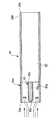
図1において、例えば、直列4気筒の内燃機関としてのエンジン21には排気マニホールド22が接続されており、この排気マニホールド22には排気装置23が接続されている。Embodiments of an exhaust pipe component and an exhaust device for an internal combustion engine according to the present invention will be described below with reference to the drawings.
(First embodiment)
FIGS. 1-17 is a figure which shows 1st Embodiment of the exhaust pipe component which concerns on this invention, and the exhaust apparatus of an internal combustion engine.
First, the configuration will be described.
In FIG. 1, for example, an exhaust manifold 22 is connected to an
なお、エンジン21は、直列4気筒に限らず、直列3気筒または直列5気筒以上であってもよく、左右に分割されたそれぞれのバンクに3気筒以上の気筒を有するV型エンジンであってもよい。 The
排気マニホールド22は、エンジン21の第1気筒から第4気筒にそれぞれ連通する排気ポートにそれぞれ接続される4つの排気枝管22a(図示1つ)と、排気枝管22aの下流側を集合させる排気集合管22bとから構成されており、エンジン21の各気筒から排気される排気ガスが排気枝管22aを介して排気集合管22bに導入されるようになっている。 The exhaust manifold 22 collects four
排気装置23は、触媒コンバータ24、円筒状のフロントパイプ25、円筒状のセンターパイプ26、消音器としてのマフラ27および円筒状のテールパイプ28を備えており、この排気装置23は、車体の床下に弾性的に垂下されるようにしてエンジン21の排気ガスの排気方向下流側に設置されている。
なお、上流とは排気ガスの排気方向の上流を示し、下流とは排気ガスの排気方向の下流を示すものである。The
The upstream indicates the upstream in the exhaust direction of the exhaust gas, and the downstream indicates the downstream in the exhaust direction of the exhaust gas.
触媒コンバータ24の上流端は、排気集合管22bの下流端に接続されており、触媒コンバータ24の下流端は、フロントパイプ25に接続されている。この触媒コンバータ24は、ハニカム基材または粒状の活性アルミナ製担体に白金、パラジウム等の触媒を付着させたものが本体ケースに収納されたものから構成され、NOxの還元やCO、HCの酸化を行うようになっている。 The upstream end of the
また、フロントパイプ25の下流端にはセンターパイプ26の上流端が接続されており、センターパイプ26の下流側は、排気音の消音を行うマフラ27に接続されている。 Further, the upstream end of the
図2において、マフラ27は、中空筒状に形成されたアウタシェル31と、アウタシェル31の両端を閉塞するエンドプレート32、33とを備えている。
アウタシェル31内には仕切板34が設けられており、この仕切板34によってアウタシェル31内は、排気ガスを拡張して消音するための拡張室35およびヘルムホルツ共鳴によって特定の周波数の排気音を消音するための共鳴室36に区画されている。In FIG. 2, the
A
また、エンドプレート32と仕切板34にはそれぞれ挿通孔32a、34aが形成されており、この挿通孔32a、34aにはセンターパイプ26の下流側(以下、センターパイプ26の下流側をインレットパイプ部26Aという)が挿通されている。 The
このインレットパイプ部26Aは、拡張室35および共鳴室36に収納されるようにしてエンドプレート32および仕切板34に支持されており、下流開口端26bが共鳴室36に開口している。 The
また、インレットパイプ部26Aにはインレットパイプ部26Aの軸線方向(排気ガスの排気方向)および周方向に複数の小孔26aが形成されており、インレットパイプ部26Aの内部と拡張室35とは、小孔26aを介して連通している。 The
したがって、センターパイプ26のインレットパイプ部26Aを通してマフラ27に導入される排気ガスは、小孔26aを介して拡張室35に導入されるとともに、インレットパイプ部26Aの下流開口端26bから共鳴室36に導入される。 Therefore, the exhaust gas introduced into the
そして、共鳴室36に導入される排気ガスは、ヘルムホルツ共鳴によって特定の周波数の排気音が消音される。具体的には、共鳴室36は、共鳴室36の容積を大きくしたり、共鳴室36内に突出するセンターパイプ26の突出長さを長くすることにより、共鳴周波数を低周波数側にチューニングすることができ、共鳴室36の容積を小さくしたり、共鳴室36内に突出するセンターパイプ26の突出部分の長さを短くすることにより、共鳴周波数を高周波数側にチューニングすることができるようになっている。 The exhaust gas introduced into the
また、仕切板34とエンドプレート33にはそれぞれ挿通孔34b、33aが形成されており、この挿通孔34b、33aにはテールパイプ28の上流部(一端部)28Aが挿通されている。 Further, insertion holes 34b and 33a are formed in the
テールパイプ28の上流部28Aの上流端には上流開口端28aが設けられており、テールパイプ28の上流部28Aは、上流開口端28aが拡張室35に開口するようにして挿通孔34b、33aに挿通されることにより、マフラ27に接続されている。 An upstream opening
また、テールパイプ28の下流部(他端部)28Bの下流端には下流開口端28bが形成されており、この下流開口端28bは、大気に連通している。このため、マフラ27の拡張室35からテールパイプ28の上流開口端28aに導入された排気ガスは、テールパイプ28を通して下流開口端28bから大気に排出される。 A downstream opening
すなわち、本実施の形態のテールパイプ28は、上流部28Aにエンジン21から排出された排気ガスの排気方向上流側のマフラ27に接続される上流開口端28aを有するとともに、下流部28Bに排気ガスを大気に排出するための下流開口端28bを有している。 That is, the
ここで、テールパイプ28の上流部28Aおよび下流部28Bは、上流開口端28aおよび下流開口端28bを含んで所定の長さを有するテールパイプ28の上流側と下流側の部分を示す。 Here, the
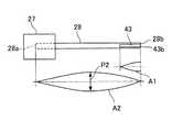
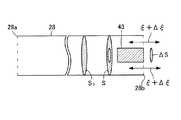
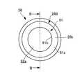
また、図3〜図5に示すように、テールパイプ28は、パイプ本体40と排気管部品41とを備えており、このパイプ本体40と排気管部品41とが一体化されたものから構成されている。すなわち、排気管部品41は、テールパイプ28の一部であるテールパイプ28の下流部28Bを構成している。
排気管部品41は、中空部材42と、短管43と、中空部材42と短管43の間に介装されたブラケット44a、44bとから構成されている。As shown in FIGS. 3 to 5, the
The
中空部材42の上流開口端(中空部材の軸線方向他端)42aは、パイプ本体40の外径よりも大径の内径を有する拡径部を構成しており、この上流開口端42aがパイプ本体40の下流端40aの外周部に溶接等によって固定されることで中空部材42がパイプ本体40に固定される。 The upstream opening end (the other axial end of the hollow member) 42a of the
すなわち、本実施の形態の中空部材42は、パイプ本体40の軸線方向に連接されている。なお、中空部材42をパイプ本体40に取付ける方法としては、溶接以外にボルト等を用いてもよい。また、中空部材42は、パイプ本体40の内径と同一の内径を有しており、テールパイプ28は、軸線方向に亘って同一の内径を有している。 That is, the
また、短管43の外周部は、板状のブラケット44a、44bの内周部に溶接等によって固定されており、このブラケット44a、44bの外周部は、中空部材42の内周部に溶接等によって固定されている。このため、短管43は、ブラケット44a、44bを介して中空部材42に取付けられている。 The outer periphery of the
また、短管43は、軸線方向他端を構成する上流端に開口端43aを有するとともに、軸線方向一端を構成する下流端に閉口端である底板43bを有しており、有底筒状に形成されている。 The
また、短管43の断面積は、軸線方向に亘って均一になっており、短管43の軸線方向中心軸は、テールパイプ28の軸線方向中心軸と同一の中心軸となるようにテールパイプ28の中心軸線上に設置されている。 Further, the cross-sectional area of the
本実施の形態の排気管部品41は、パイプ本体40に取付けられてパイプ本体40と共にテールパイプ28を構成するため、中空部材42の下流開口端(軸線方向他端)42bがテールパイプ28の下流開口端28bを構成するようになっている。 Since the
また、短管43の底板43bは、中空部材42の下流開口端(中空部材42の軸線方向一端)であるテールパイプ28の下流開口端28bと同一面上に位置しており、短管43の開口端43aは、底板43bからパイプ本体40側に向かって所定の長さで延在している。 The
本実施の形態では、短管43の底板43bが、テールパイプ28の下流開口端28bと同一面上に位置しているため、短管43の底板43bがテールパイプ28内で発生する気柱共鳴の音圧分布の定在波の節に位置している。なお、短管43の底板43bは、気柱共鳴の音圧分布の定在波の節から、上流側または下流側に若干量だけずれていてもよい。 In the present embodiment, since the
ここで、テールパイプ28内に発生する気柱共鳴の定在波は、テールパイプ28の管長Lと定在波の波長λとが特定の関係にあるとき、振幅が著しく大きくなり、気柱共鳴が生じる。この気柱共鳴は、テールパイプ28の管長Lを半波長とした周波数を基本として、その半波長の自然数倍の波長の気柱共鳴が発生して音圧が増大する。 Here, the standing wave of the air column resonance generated in the
具体的には、図6にテールパイプ28内で発生する気柱共鳴の定在波の粒子速度分布を示すように、基本振動(一次成分)の気柱共鳴の波長λ1は、テールパイプ28の管長Lの略2倍となり、二次成分の気柱共鳴の波長λ2は、管長Lの略1倍となる。 Specifically, as shown in FIG. 6 showing the particle velocity distribution of the standing wave of air column resonance generated in the
図6から明らかなように、それぞれの定在波は、テールパイプ28の上流開口端28aおよび下流開口端28bが粒子速度の腹となり、この粒子速度は、上流開口端28aおよび下流開口端28bで最大となる。 As is clear from FIG. 6, each standing wave has antinodes of the particle velocity at the upstream opening
また、一次成分および二次成分の気柱共鳴の定在波の音圧分布は、図7に示すように、粒子速度分布の腹と節とがそれぞれ逆となってテールパイプ28の上流開口端28aおよび下流開口端28bが音圧分布の節となり、音圧は、上流開口端28aおよび下流開口端28bで最小となる。 Further, as shown in FIG. 7, the sound pressure distribution of the standing wave of the air column resonance of the primary component and the secondary component is such that the antinodes and nodes of the particle velocity distribution are reversed, and the upstream opening end of the
また、短管43は、テールパイプ28内に生じる気柱共鳴の定在波の波長λに対して1/8・λm(但し、mは、次数)以下の長さに設定されている。本実施の形態では、短管43がテールパイプ28の下流部28Bに設けられており、図6に示すように、λ1=2Lであるため、短管43の長さは、テールパイプ28の管長Lの1/4の長さに設定されている。
なお、短管43は、気柱共鳴の定在波の波長λに対して1/8・λm以下の長さ、すなわち、テールパイプ28の管長Lの1/4以下の長さに設定してもよい。Further, the
The
また、本実施の形態では、同一の内径を有する直管のテールパイプ28の下流部28Bに軸線方向に沿ってテールパイプ28の管長Lの1/4の長さで延在する短管43が設けられるため、テールパイプ28の排気通路45の単位長さ当たりの体積に対して下流部28Bの排気通路45aの単位長さ当たりの体積が小さくなるように、短管43と下流部28Bの間の排気通路45の体積が小さくなっている。 In the present embodiment, a
このため、図6、図7に示すように、気柱共鳴の定在波の音圧分布の節において気柱共鳴の粒子速度が最大となることを利用して、テールパイプ28の下流部28Bの単位長さ当たり体積を小さくすることにより、テールパイプ28の下流部28Bの気柱共鳴の粒子速度を上昇させることができる。 Therefore, as shown in FIGS. 6 and 7, the
また、短管43は、短管43が取付けられていない状態のテールパイプ28の排気通路45の体積に対して、短管43をテールパイプ28に取付けたときのテールパイプ28の排気通路45の体積の減少量が2.5%以上となるような大きさに設定されている。
なお、本実施の形態では、テールパイプ28の下流部28Bにブラケット44a、44bを設けているが、ブラケット44a、44bは板状であるため、ブラケット44a、44bの断面積は、短管43の断面積よりも小さい。このため、排気通路45の体積の減少量は、短管43の断面積に大きく依存される。Further, the
In the present embodiment, the
なお、この短管43の大きさとは、短管43を中実軸と見なした場合の短管43の体積を表し、短管43が取付けられていない状態のテールパイプ28の排気通路45の体積に対して、短管43の体積は、2.5%以上となる。 The size of the
ここで、排気通路45は、テールパイプ28、すなわち、パイプ本体40と中空部材42とによって囲まれる空間の全てであり、排気通路45の中で短管43の外周部と中空部材42とによって囲まれる空間が排気通路45aを構成している。 Here, the
次に、作用を説明する。
エンジン21の運転時にエンジン21の各気筒から排気される排気ガスは、排気マニホールド22から触媒コンバータ24に導入され、触媒コンバータ24によってNOxの還元やCO、HCの酸化が行われる。Next, the operation will be described.
Exhaust gas exhausted from each cylinder of the
触媒コンバータ24から排気される排気ガスは、フロントパイプ25およびセンターパイプ26を通してマフラ27に導入される。マフラ27に導入される排気ガスは、インレットパイプ部26Aの小孔26aを介して拡張室35に導入されるとともに、インレットパイプ部26Aの下流開口端26bから共鳴室36に導入され、共鳴室36に導入される排気ガスは、ヘルムホルツ共鳴によって特定の周波数の排気音が消音される。 Exhaust gas exhausted from the
拡張室35に導入された排気ガスは、テールパイプ28の上流開口端28aを通してテールパイプ28内に導入された後、テールパイプ28の下流開口端28bを通して大気に排出される。 The exhaust gas introduced into the
また、エンジン21の運転時にテールパイプ28に導入される排気ガスの排気音は、エンジン21の回転数に応じて変化する排気脈動の入射波であり、この入射波は、エンジン21の回転数が増大するにつれて周波数が大きくなるものである。 Further, the exhaust sound of the exhaust gas introduced into the
エンジン21の運転時の排気脈動による入射波がテールパイプ28に導入されると、この入射波がテールパイプ28の下流開口端28bで、所謂、開口端反射する。この反射波は、入射波と同じ位相で入射波と逆向きとなる。また、この反射波は、再び上流開口端28aでこの反射波と同位相で逆向きに開口端反射を行う。この反射波が今度は入射波となり、上流開口端28aで反射波となる。 When an incident wave due to exhaust pulsation during operation of the
開口端反射が起こる理由としては、テールパイプ28内を流れる排気ガスの圧力は高く、テールパイプ28の下流開口端28bの外側は圧力が低いため、入射波が勢いよく大気に飛び出すことで下流開口端28b内の排気ガスの圧力が低くなり、この低圧部がテールパイプ28を上流開口端28aに向かって進行し始めるからである。 The reason for the reflection at the opening end is that the pressure of the exhaust gas flowing in the
したがって、反射波は、入射波と同位相で逆向きとなるのである。また、上流開口端28a側で反射波が発生する理由も下流開口端28bで反射波が発生する理由と同様である。 Therefore, the reflected wave has the same phase as the incident wave and reverse direction. The reason why the reflected wave is generated on the upstream opening
そして、下流開口端28bに向かう入射波と下流開口端28bと逆向きの反射とが干渉することで、図6に示すように、テールパイプ28の上流開口端28aおよび下流開口端28bにおいて粒子速度が最大となるような定在波ができる。 Then, the incident wave traveling toward the downstream opening
また、この定在波は、テールパイプ28の管長Lと定在波の波長λとが特定の関係にあるとき、振幅が著しく大きくなり、気柱共鳴が生じる。この気柱共鳴は、テールパイプ28の管長Lを半波長とした周波数を基本として、その半波長の自然数倍の波長の気柱共鳴が発生して音圧が増大する。 Further, when the standing
ここで、音速をc、テールパイプ28の長さをL、次数をmとしたときのテールパイプ28の気柱共鳴周波数fmは、
fm=(c/2L)・m............(2)
で表される。Here, the air column resonance frequency fm of the
fm = (c / 2L) · m (2)
It is represented by
また、図8に示すように、エンジン21の排気脈動の周波数は、エンジン21の回転数が増大するのに伴って増大するようになっており、エンジン21の回転数に対応した気柱共鳴による排気音の一次成分f1と二次成分f2とで排気音の音圧レベル(dB)が高くなる。 Further, as shown in FIG. 8, the frequency of the exhaust pulsation of the
したがって、管長が長いテールパイプ28(例えば、テールパイプ28の管長が1.5m以上)を用いる場合には、エンジン21の回転数が低い常用回転域(2000rpm〜5000rpm)で気柱共鳴が発生してしまうことがある。 Therefore, when the
特に、気柱共鳴の一次成分f1の音圧のピーク(音圧分布の腹の幅)は、二次成分f2の音圧のピークよりも大きいため、常用回転域でこもり音と呼ばれる不快な騒音が発生してしまい、排気騒音の悪化の原因となり、運転者に不快感を与えてしまうことになる。 In particular, since the peak of the sound pressure of the primary component f1 of the air column resonance (the width of the antinode of the sound pressure distribution) is larger than the peak of the sound pressure of the secondary component f2, the unpleasant noise called a booming sound in the normal rotation range. Will occur, causing exhaust noise to become worse and discomforting the driver.
そこで、本実施の形態は、エンジン21の常用回転域において気柱共鳴周波数の一次成分f1および二次成分f2の気柱共鳴の音圧のレベルを低減し、排気騒音を低減して運転者に不快感を与えるのを防止するようにした。 Therefore, the present embodiment reduces the level of sound pressure of air column resonance of the primary component f1 and the secondary component f2 of the air column resonance frequency in the normal rotation region of the
まず、気柱共鳴の音圧レベルを低減することができる理由を説明する。
短管43が設けられていないテールパイプ28内に気柱共鳴が発生しているときの気柱共鳴の定在波の一次成分f1の音圧分布を図9に示すと、テールパイプ28の上流開口端28aおよび下流開口端28bが気柱共鳴の定在波の音圧分布の節となるため、上流開口端28aおよび下流開口端28bにおいて、気柱共鳴の定在波の音圧が最小となる。また、中央部が気柱共鳴の定在波の音圧分布の腹となるため、中央部において、気柱共鳴の定在波の音圧がピークP1となる。First, the reason why the sound pressure level of air column resonance can be reduced will be described.
The sound pressure distribution of the primary component f1 of the standing wave of air column resonance when air column resonance is generated in the
また、テールパイプ28内に気柱共鳴が発生しているときの気柱共鳴の一次成分f1の定在波の粒子速度分布を図10に示すと、テールパイプ28の上流開口端28aおよび下流開口端28bが気柱共鳴の定在波の流速度分布の腹となるため、上流開口端28aおよび下流開口端28bで定在波の粒子速度が最大となる。また、中央部が気柱共鳴の定在波の粒子速度分布の節となるため、中央部では粒子が移動しない。 Moreover, when the particle velocity distribution of the standing wave of the primary component f1 of the air column resonance when the air column resonance is generated in the
本実施の形態では、テールパイプ28の下流部28Bの内部に、開口端43aと閉口端である底板43bを有する有底筒状の短管43を設け、この底板43bを、テールパイプ28内で発生する気柱共鳴の定在波の音圧分布の節に位置させたので、気柱共鳴の発生時に、定在波の粒子速度が最大となる音圧分布の節の位置において、テールパイプ28内の気柱共鳴が有するポテンシャルエネルギーを短管43に内に蓄積することができる。 In the present embodiment, a bottomed cylindrical
すなわち、気柱共鳴が発生する系が有する力学的エネルギーは、運動エネルギーとポテンシャルエネルギー(排気ガスの質量)の和で表され、力学的エネルギーは、保存されることが知られている。 That is, it is known that the mechanical energy possessed by the system in which air column resonance occurs is represented by the sum of kinetic energy and potential energy (exhaust gas mass), and the mechanical energy is preserved.
このポテンシャルエネルギーについて考察する。
音圧分布の節の位置は、音圧が最小となる反面、粒子速度が最大となるので、テールパイプ28内の気柱共鳴が有するポテンシャルエネルギーは、図11に示すように、音圧が低い位置に設けられた短管43内に蓄積され、底板43b側の音圧が開口端43a側の音圧に比べて高いモードとなるポテンシャルエネルギーA1となり、このポテンシャルエネルギーA1は、外部に放出されない。Consider this potential energy.
The position of the nodes of the sound pressure distribution has the lowest sound pressure but the highest particle velocity. Therefore, the potential energy of the air column resonance in the
この短管43内に蓄積されるポテンシャルエネルギーA1は、テールパイプ内の排気ガスが持つポテンシャルエネルギーによって行われるため、系としては、ポテンシャルエネルギーの変化が生じないが、力学的エネルギーの保存則により、図9に示すテールパイプ28内のポテンシャルエネルギーAは、短管43内のポテンシャルエネルギーA1と、短管43を除いたテールパイプ28内のポテンシャルエネルギーA2とに分散されて、短管43を除いたテールパイプ28内のポテンシャルエネルギーA2のみが外部に放出されることになる。 Since the potential energy A1 accumulated in the
すなわち、図12に示すように、テールパイプ28内のポテンシャルエネルギーAから短管43内のポテンシャルエネルギーA1(ハッチングで示す)を差し引いた残りのポテンシャルエネルギーA2(ハッチングで示す)がテールパイプ28から外部に放出される。 That is, as shown in FIG. 12, the remaining potential energy A2 (indicated by hatching) obtained by subtracting the potential energy A1 (indicated by hatching) in the
気柱共鳴による音圧レベルは、ポテンシャルエネルギーによって決まるため、ポテンシャルエネルギーを少なくすることにより、すなわち、テールパイプ28のポテンシャルエネルギーをポテンシャルエネルギーA2のみとすることにより、音圧のピークをピークP1からピークP2(図11参照)に下げて音圧レベルを低減することができる。この結果、ポテンシャルエネルギーの減少分だけ、排気騒音を低減することができる。 Since the sound pressure level due to the air column resonance is determined by the potential energy, the peak of the sound pressure is peaked from the peak P1 by reducing the potential energy, that is, by setting the potential energy of the
次に、排気ガスの運動エネルギーにおいて考えると、本実施の形態では、テールパイプ28の下流部28Bに、テールパイプ28の軸線方向に沿って延在する短管43を設け、テールパイプ28の排気通路45の単位長さ当たりの体積に対して下流部28Bの内部の排気通路45aの単位長さ当たりの体積を小さくしているため、図10に示すように、テールパイプ28内の粒子速度Bは、下流部28B内において実線で示す粒子速度B1から破線で示すB2まで上昇する。 Next, considering the kinetic energy of the exhaust gas, in the present embodiment, a
この粒子速度を運動エネルギーで考えると、運動エネルギーは、速度の二乗に比例することから、テールパイプ28の排気通路45内の運動エネルギーは、増えた粒子速度の二乗分だけ増加する。図12に運動エネルギーの増加レベルを示すと、運動エネルギーは、B1で示す位置からB3で示す位置まで飛躍的に増加する。 Considering this particle velocity in terms of kinetic energy, the kinetic energy is proportional to the square of the velocity. Therefore, the kinetic energy in the
テールパイプ28内の気柱共鳴が持つポテンシャルエネルギーAは、テールパイプ28内のポテンシャルエネルギーA2と短管43内のポテンシャルエネルギーA1に分散されているが、ポテンシャルエネルギーAは、全体として変化がないのに対して、運動エネルギーを飛躍的に増大させることができるため、ポテンシャルエネルギーと運動エネルギーの和である力学的エネルギーを増加させることができる。 The potential energy A possessed by the air column resonance in the
したがって、テールパイプ28内の気柱共鳴が持つ力学的エネルギーが保存されるようにテールパイプ28が擬似的に長くなり、気柱共鳴周波数を管長が長いテールパイプと同等の気柱共鳴周波数に下げることができる。 Therefore, the
具体的にテールパイプ28が擬似的に長くなる理由を説明する。
図13に示すように、断面積S0、管長Lのテールパイプ28の下流部28Bに短管43を設けていない場合に、このテールパイプ28内に気柱共鳴が発生した場合には、テールパイプ28の下流部28Bの定在波の粒子速度は、ξとなる。The reason why the
As shown in FIG. 13, in the case where the
次に、図14に示すように、断面積S0、長さLのテールパイプ28の上流開口端28aを原点とし、テールパイプ28の軸線方向にX軸をとり、テールパイプ28の下流部28Bに断面積ΔSの短管43を取付けて下流部28Bの断面積を小さくし、下流部28Bの断面積をS=S0−ΔSのように表した場合を考える。但し、断面積の変化ΔSは微小とする。このとき、テールパイプ28の下流部28Bの定在波の粒子速度は、ξ+Δξとなる。Next, as shown in FIG. 14, the upstream opening
なお、本実施の形態では、下記の数式を説明するための便宜上、下流部28Bの断面積をS=S0+ΔSとした場合(すなわち、拡径した場合)について説明を行う。
このテールパイプ28の下流部28BをS=S0+ΔSとする修正によってテールパイプ28内の気柱共鳴周波数が変化し、この気柱共鳴周波数の変化をテールパイプ28の長さの変化ΔLとして求めると、下記の式(3)で表すことができる。In the present embodiment, for the sake of convenience in explaining the following mathematical formula, the case where the cross-sectional area of the
By modifying the

ここで、mは、気柱共鳴周波数の一次成分、二次成分、三次成分......を表す。
テールパイプ28内に気柱共鳴が発生しているときには、気柱の各部分は圧縮および膨張を繰り返してそれぞれ異なる運動状態にあるが、気柱全体としては、力学的エネルギーが一定に保たれている。したがって、上記の式(3)が導かれる。Here, m represents a primary component, a secondary component, a tertiary component,...
When air column resonance is generated in the
次に、上記の式(3)の導出方法を説明する。
まず、運動エネルギーTを求める。単位時間当たりにテールパイプ28内のある断面を通過する空気の体積をXとすると、粒子速度は、ξ=X/Sである。空気の密度をρ0で表すと、テールパイプ28内の空気全体の運動エネルギーは、下記の式(4)で表される。Next, the derivation method of said Formula (3) is demonstrated.
First, the kinetic energy T is obtained. If the volume of air passing through a certain cross section in the
ところで、テールパイプ28内に気柱共鳴が発生しているときには、テールパイプ28内の空気全体の力学的エネルギーは、一定に保たれていると考えられる。すなわち、T+V=const、あるいは下記の式(8)となる。 By the way, when air column resonance occurs in the
本実施の形態では、短管43が収納されるテールパイプ28の下流部28Bの排気通路45aの単位長さ当たりの体積が、下流部28Bを除いたテールパイプ28の排気通路45の単位当たりの体積に対して小さくなっている。 In the present embodiment, the volume per unit length of the
すなわち、テールパイプ28の下流部28Bに短管43が設けられてテールパイプ28の下流部28Bの排気通路45aの断面積が、排気通路45の断面積よりも小さくなっているため、ΔSが−(マイナス)となる。 That is, since the
したがって、テールパイプ28の長さがΔLだけ長くなったものと等価となり、テールパイプ28が長くなった分だけ、気柱共鳴周波数の波長を長くすることができ、テールパイプ28の気柱共鳴周波数を管長が長いテールパイプと同等の気柱共鳴周波数に下げることができる。 Accordingly, this is equivalent to the length of the
そして、テールパイプ28が擬似的に長くなると、短管43の内部に蓄積していたポテンシャルエネルギーA1を除いたテールパイプ28内のポテンシャルエネルギーA2は、テールパイプ28が長くなった分だけ(伸び代ΔL分だけ)、テールパイプ28全体に分散されるため、力学的エネルギーの観点からは、テールパイプ28の内径が細くなったものと等価となる。 When the
したがって、テールパイプ28が有する気柱共鳴のポテンシャルエネルギーは、テールパイプ28の内径が擬似的に細くなった分だけ、最終的に、図12のA3のハッチングで示す大きさとなる。すなわち、気柱共鳴の音圧のピークを図12のピークAからピークA3までさらに低減することができ、音圧レベルをさらに低減することができる。 Therefore, the potential energy of air column resonance possessed by the
図15は、短管43が取付けられたときの排気通路45の体積の減少量が12.5%のテールパイプを用いてスピーカ加振試験を行ったときの排気脈動の周波数と排気音の音圧レベル(dB)との測定結果を示す図である。 FIG. 15 shows the frequency of exhaust pulsation and the sound of exhaust sound when a speaker excitation test is performed using a tail pipe with a volume reduction of 12.5% when the
図15においては、実線は、短管43が設けられていないテールパイプ28の排気脈動を示し、破線は、短管43が設けられた本実施の形態のテールパイプ28の排気脈動を示すものである。 In FIG. 15, the solid line indicates the exhaust pulsation of the
本実施の形態では、図15に示すように、テールパイプ28内に発生する気柱共鳴の一次成分f1の周波数を下げることができるとともに、一次成分f1の音圧レベルを確実に低減できることが確認された。 In the present embodiment, as shown in FIG. 15, it is confirmed that the frequency of the primary component f1 of the air column resonance generated in the
また、スピーカ加振試験を行った結果、音圧のピークの低減と気柱共鳴周波数を下げることが可能なテールパイプ28の排気通路45の体積の減少量の最低値は、2.5%であり、体積の減少量が2.5%未満の場合には音圧を低減する効果を期待できないことが確認された。 As a result of the speaker vibration test, the minimum value of the volume reduction of the
このように本実施の形態では、テールパイプ28の一部を構成するようにテールパイプ28に排気管部品41を設け、排気管部品41が、テールパイプ28内に生じる気柱共鳴の音圧分布の節を含んだ領域に位置するようにしてテールパイプ28の軸線方向に連接される中空部材42と、中空部材42の内部にテールパイプ28の軸線方向に沿って所定長延在し、上流端に開口端43aを有するとともに、下流端に気柱共鳴の定在波の音圧分布の節に位置する閉口端としての底板43bを有する短管43とから構成したので、気柱共鳴の発生時に、定在波の粒子速度が最大となる音圧分布の節の位置において、テールパイプ28内の気柱共鳴が有するポテンシャルエネルギーAを、短管43内のポテンシャルエネルギーA1と、短管43を除いたテールパイプ28内のポテンシャルエネルギーA2とに分散して、短管43を除いたテールパイプ28内のポテンシャルエネルギーA2のみを外部に放出することができ、音圧のピークを低減することができる。このため、排気騒音を低減することができる。 As described above, in the present embodiment, the
また、本実施の形態では、テールパイプ28の排気通路45の単位長さ当たりの体積に対して下流部28Bの排気通路45aの単位長さ当たりの体積が小さくなるように、短管43と下流部28Bの間の排気通路45を絞るようにしたので、テールパイプ28を擬似的に長くして気柱共鳴周波数を管長が長いテールパイプと同等の気柱共鳴周波数に下げることができるとともに、短管43に蓄積されたポテンシャルエネルギーA1を除いたポテンシャルエネルギーA2をテールパイプ28の伸び代分だけテールパイプ28全体に分散させてテールパイプ28の内径を擬似的に細くすることができる。このため、気柱共鳴の音圧のピークをさらに低減して気柱共鳴の音圧レベルをさらに低減することができる。 Further, in the present embodiment, the
したがって、テールパイプ28内に発生する気柱共鳴周波数を、管長が長いテールパイプと同等の気柱共鳴周波数に下げることができるため、気柱共鳴周波数を、低周波になる程に聞こえ難いA特性(人の耳に近い特性)を利用して実質的に下げることができる(図16参照)。 Therefore, since the air column resonance frequency generated in the
また、気柱共鳴周波数を管長が長いテールパイプと同等の気柱共鳴周波数に下げることができるため、気柱共鳴の発生時に、音源となるエンジン21の回転数をエンジン21の回転振動が小さい低回転域に下げることができる。これに加えて、気柱共鳴発生時の音圧レベルを大幅に低減することができるので、結果的に、排気騒音を大幅に低減することができる。 Further, since the air column resonance frequency can be lowered to an air column resonance frequency equivalent to that of a tail pipe having a long tube length, the rotation speed of the
特に、本実施の形態では、気柱共鳴の定在波の音圧分布の節となるテールパイプ28の下流開口端28bを排気管部品41から構成したので、気柱共鳴の音圧のピークが最も大きい一次成分f1の音圧のピークを確実に低減することができるとともに、一次成分f1の気柱共鳴周波数を管長が長いテールパイプ28と同等の気柱共鳴周波数に下げることができるため、排気騒音をより一層低減することができる。 In particular, in the present embodiment, since the downstream opening
これに加えて、気柱共鳴の一次成分f1を基本とした二次成分f2の音圧のピークも低減することができるため、エンジン21の常用回転域において排気騒音をより一層低減することができる。すなわち、図8に示すように、気柱共鳴の一次成分f1と一次成分の倍音である気柱共鳴の二次成分f2の音圧のピークを点線で示す位置から実線で示す位置に低減することができるため、排気騒音を大幅に低減することができる。 In addition, since the peak of the sound pressure of the secondary component f2 based on the primary component f1 of the air column resonance can be reduced, the exhaust noise can be further reduced in the normal rotation region of the
したがって、従来用いられていたマフラを廃止することができるとともに、大容量の共鳴室36を不要にしてマフラ27を小型化することができる。このため、排気装置23の重量を低減することができるとともに、排気装置23の製造コストを低減することができる。 Therefore, the conventionally used muffler can be eliminated, and the
また、本実施の形態では、短管43を、テールパイプ28内に生じる気柱共鳴の定在波の波長λに対して1/8・λmの長さに設定し、短管43の底板43bを、テールパイプ28内に生じる気柱共鳴の定在波の音圧分布の節に位置させたので、短管43を気柱共鳴の定在波の粒子速度が大きい位置に位置させることができ、ポテンシャルエネルギーの減少量に対してテールパイプ28内の排気ガスの運動エネルギーをより効果的に大きくすることができる。 Further, in the present embodiment, the
これに対して、短管43を気柱共鳴の定在波の波長λに対して1/8・λmを越える長さに設定すると、ポテンシャルエネルギーが大きく粒子速度の小さい位置に短管43の一部が位置してしまうことになるので、テールパイプ28内のポテンシャルエネルギーの減少量に対してテールパイプ28内の運動エネルギーの増加量を大きくすることができないため、結果的に、テールパイプ28内の力学的エネルギーが減少してしまう。 On the other hand, when the length of the
このため、テールパイプ28が擬似的に短くなって、気柱共鳴周波数を上げてしまうことになるので、好ましくない。したがって、短管43の長さは、気柱共鳴の定在波の波長λに対して1/8・λm以下の長さに設定するのが好ましい。 For this reason, the
なお、本実施の形態では、テールパイプ28をパイプ本体40と排気管部品41とから構成しているが、テールパイプを、パイプ本体40と排気管部品41が一体成形された1本のテールパイプから構成してもよい。このようにすれば、パイプ本体40と排気管部品41を別々に製造してパイプ本体40に排気管部品41を取付ける必要がないため、テールパイプの製造を容易に行うことができるとともに、テールパイプの製造コストを低減することができる。 In the present embodiment, the
また、本実施の形態では、排気管部品41をテールパイプ28の下流部28Bから構成しているが、これに限らず、図17に示すように、一体成形されたテールパイプ28の上流部28Aと下流部28Bの内部、すなわち、気柱共鳴の音圧分布の節を含んだ領域に短管43、46に収納してもよい。 Further, in the present embodiment, the
この場合には、短管46の底板46bを、テールパイプ28内で発生する気柱共鳴の定在波の音圧分布の節に位置させ、短管46の開口端46aを底板46bから下流開口端28bに向かって所定延在させることにより、テールパイプ28の上流部28Aの排気通路45aの単位長さ当たりの体積を、テールパイプ28の排気通路45の単位体積当たりの体積通路よりも小さくすることができる。 In this case, the
このように、テールパイプ28の上流部28Aおよび下流部28Bの両方の単位長さ当たりの体積を小さくするようにすれば、テールパイプ28内に発生する気柱共鳴が持つポテンシャルエネルギーをより一層低減することができるとともに、テールパイプ28の上流部28Aおよび下流部28Bの両方で気柱共鳴の定在波の粒子速度を上昇させて力学的エネルギーをより一層増加させることができる。 Thus, if the volume per unit length of both the
また、テールパイプ28の上流部28Aの内部のみに短管46を設け、テールパイプ28の上流部28Aの排気通路45aの単位長さ当たりの体積を、テールパイプ28の排気通路45の単位体積当たりの体積通路よりも小さくしてもよい。このようにしてもテールパイプ28の下流部28Bに短管43を設けたものと同様の効果を得ることができる。 In addition, the
また、本実施の形態では、テールパイプ28の上流部28Aをパイプ本体40と別体の排気管部品41から構成し、この排気管部品41の中空部材42の上流開口端がテールパイプ28の上流開口端28aを構成するようにしてもよい。 Further, in the present embodiment, the
(第2の実施の形態)
図18、図19は、本発明に係る排気管部品および内燃機関の排気装置の第2の実施の形態を示す図であり、第1の実施の形態と同一の構成には同一番号を付して説明を省略する。(Second Embodiment)
18 and 19 are views showing a second embodiment of an exhaust pipe component and an exhaust device for an internal combustion engine according to the present invention. The same components as those in the first embodiment are denoted by the same reference numerals. The description is omitted.
図18、図19において、短管61は、テールパイプ28の下流部28Bの下流開口端28bからテールパイプ28の中心軸Cに向かって折り曲げられた閉口端である底板61aと、底板61aからテールパイプ28の上流開口端28aに向かって折り曲げられてテールパイプ28と平行に延在し、上流端においてテールパイプ28の下流部28Bと共に開口端61cを構成する環状部材61bとを備えている。したがって、短管61は、下流部28Bと一体の有底筒状に形成されている。 18 and 19, a
本実施の形態のテールパイプ28は、下流部28Bが中空部材を構成している。中空部材および短管61は、テールパイプ28と一体成形されたものであり、テールパイプ28は、1本のパイプから構成されている。 In the
なお、テールパイプ28の下流部28Bをテールパイプ28と別体の中空部材から構成することにより、中空部材からなる下流部28Bと短管61とによって排気管部品を構成し、この排気管部品をテールパイプ28に後付けするようにしてもよい。 By forming the
すなわち、下流部28Bを排気管部品から構成する場合には、下流部28Bをテールパイプ28から取り外した状態において、下流部28Bの軸線方向一端からテールパイプ28の中心軸Cに向かって折り曲げられた閉口端である底板61aと、底板61aから下流部28Bの軸線方向他端に向かって折り曲げられて下流部28Bと平行に延在する環状部材61bを備えたものとなる。 That is, when the
一方、短管61の軸線方向一端である底板61aは、下流開口端28bと同一面上に位置しており、短管61の環状部材61bは、底板61aから上流開口端28aに向かって延在している。本実施の形態の短管61は、テールパイプ28内に生じる気柱共鳴の定在波の波長λに対して1/8・λmの長さ、すなわち、テールパイプ28の管長Lの1/4の長さに設定されている。 On the other hand, the
なお、短管61は、気柱共鳴の定在波の波長λに対して1/8・λm以下の長さ、すなわち、テールパイプ28の管長Lの1/4以下の長さに設定してもよい。 The
また、本実施の形態では、短管61の底板61aが下流開口端28bと同一面上に位置しているため、短管61の底板61aは、テールパイプ28内で発生する気柱共鳴の音圧分布の定在波の節に位置している。なお、短管61の底板61aは、音圧分布の節の位置に対して上流側または下流側に若干ずれていてもよい。 In the present embodiment, since the
また、テールパイプ28の排気通路62の単位長さ当たりの体積に対して、下流部28Bの排気通路62aの単位長さ当たりの体積が小さくなるように排気通路62aの体積が小さくなっている。 Further, the volume of the
具体的には、短管61は、短管61が取付けられていない状態のテールパイプ28の排気通路62の体積に対して、短管61をテールパイプ28に取付けたときのテールパイプ28の排気通路62の体積の減少量が2.5%以上となるような大きさに設定されている。 Specifically, the
また、排気通路62は、テールパイプ28によって囲まれる空間の全てであり、排気通路62の中で環状部材61bの内周部によって囲まれる空間が排気通路62aを構成している。 The
このような構成の短管61を有するテールパイプ28にあっても、テールパイプ28内のポテンシャルエネルギーAを、短管61内のポテンシャルエネルギーA1と、短管61を除いたテールパイプ28内のポテンシャルエネルギーA2とに分散させて、短管61を除いたテールパイプ28内のポテンシャルエネルギーA2のみを外部に放出して、音圧のピークを下げることができる。 Even in the
また、テールパイプ28を擬似的に長くして気柱共鳴周波数を管長が長いテールパイプと同等の気柱共鳴周波数に下げることができるとともに、ポテンシャルエネルギーをテールパイプ28の伸び代分だけテールパイプ28全体に分散させてテールパイプ28の内径を擬似的に細くすることができ、気柱共鳴の音圧のピークをさらに低減して気柱共鳴の音圧レベルをさらに低減することができる。 In addition, the
この結果、第1の実施の形態と同様に排気騒音を低減することができ、従来用いられていたマフラを廃止するとともにマフラ27を小型化して、排気装置23の重量を低減することができるとともに、排気装置23の製造コストを低減することができる。 As a result, the exhaust noise can be reduced as in the first embodiment, the conventionally used muffler can be eliminated, the
また、本実施の形態では、短管61をテールパイプ28の下流開口端28bから折り曲げられた底板61aと環状部材61bとから構成したので、短管61をテールパイプ28の内周部に取付けるためのブラケットを不要にすることができ、テールパイプ28の製造コストを低減することができるとともに、テールパイプ28の軽量化を図ることができる。 Further, in the present embodiment, the
なお、本実施の形態では、短管61をテールパイプ28の下流部28Bに設けているが、これに限らず、短管61のテールパイプ28の上流部28Aに設けてもよく、図20に示すように、上流部28Aと下流部28Bの両方に設けてもよい。 In the present embodiment, the
特に、テールパイプ28の上流部28Aと下流部28Bの両方に短管61を設ければ、テールパイプ28内に発生する気柱共鳴のポテンシャルエネルギーをより一層低減することができるとともに、テールパイプ28の上流部28Aおよび下流部28Bの両方で気柱共鳴の定在波の粒子速度を上昇させて力学的エネルギーをより一層増加させることができる。 In particular, if the
(第3の実施の形態)
図21、図22は、本発明に係る排気管部品および内燃機関の排気装置の第3の実施の形態を示す図であり、第1の実施の形態と同一の構成には同一番号を付して説明を省略する。(Third embodiment)
FIGS. 21 and 22 are views showing a third embodiment of the exhaust pipe component and the exhaust device of the internal combustion engine according to the present invention. The same components as those in the first embodiment are denoted by the same reference numerals. The description is omitted.
図21、図22において、テールパイプ28の上流部28Aの内部には短管65が設けられており、この短管65は、ブラケット66a、66bを介してテールパイプ28の上流部28Aに取付けられている。このため、短管65の軸線方向中心軸は、テールパイプ28の軸線方向中心軸と同一の中心軸となるようにテールパイプ28の中心軸線上に設置されている。 21 and 22, a
また、短管65は、軸線方向他端を構成する下流端に開口端65aを有するとともに、軸線方向一端を構成する上流端に閉口端である底板65bを有し、テールパイプ28の軸線方向に沿って所定長の長さで延在する有底筒状に形成されている。 The
また、短管65の底板65bは、球面または放物面に形成されており、短管65は、底板65b側の断面積が、開口端65a側の断面積よりも小さく形成されている。 Further, the
本実施の形態のテールパイプ28は、上流部28Aが中空部材を構成している。この中空部材は、テールパイプ28と一体成形されたものであり、テールパイプ28は、1本のパイプから構成されている。 In the
なお、テールパイプ28の上流部28Aをテールパイプ28と別体の中空部材から構成することにより、中空部材からなる上流部28Aと短管65とによって排気管部品を構成し、この排気管部品をテールパイプ28に後付けするようにしてもよい。 By configuring the
また、本実施の形態では、短管65の底板65bが上流開口端28aと同一面上に位置しているため、短管65の底板65bは、テールパイプ28内で発生する気柱共鳴の音圧分布の定在波の節に位置している。なお、短管65の底板65bは、音圧分布の節の位置に対して上流側または下流側に若干ずれていてもよい。 In the present embodiment, since the
また、本実施の形態の短管65は、テールパイプ28内に生じる気柱共鳴の定在波の波長λに対して1/8・λmの長さ、すなわち、テールパイプ28の管長Lの1/4の長さに設定されている。
なお、短管65は、気柱共鳴の定在波の波長λに対して1/8・λm以下の長さ、すなわち、テールパイプ28の管長Lの1/4以下の長さに設定してもよい。Further, the
The
また、本実施の形態では、テールパイプ28の排気通路67の単位長さ当たりの体積に対して、下流部28Bの排気通路67aの単位長さ当たりの体積が小さくなるように排気通路67aの体積が小さくなっている。 In the present embodiment, the volume of the
具体的には、短管65は、短管65が取付けられていない状態のテールパイプ28の排気通路67の体積に対して、短管65をテールパイプ28に取付けたときのテールパイプ28の排気通路67の体積の減少量が2.5%以上となるような大きさに設定されている。 Specifically, the
また、排気通路67は、テールパイプ28によって囲まれる空間の全てであり、排気通路67の中で短管65の外周部と下流部28Bの内周部とによって囲まれる空間が排気通路67aを構成している。 The
このような構成の短管65を有するテールパイプ28にあっても、テールパイプ28内のポテンシャルエネルギーAを、短管65内のポテンシャルエネルギーA1と、短管65を除いたテールパイプ28内のポテンシャルエネルギーA2とに分散させて、短管65を除いたテールパイプ28内のポテンシャルエネルギーA2のみを外部に放出して、音圧のピークを下げることができる。 Even in the
また、テールパイプ28を擬似的に長くして気柱共鳴周波数を管長が長いテールパイプと同等の気柱共鳴周波数に下げることができるとともに、ポテンシャルエネルギーをテールパイプ28の伸び代分だけテールパイプ28全体に分散させてテールパイプ28の内径を擬似的に細くすることができ、気柱共鳴の音圧のピークをさらに低減して気柱共鳴の音圧レベルをさらに低減することができる。 In addition, the
この結果、第1の実施の形態と同様に排気騒音を低減することができ、従来用いられていたマフラを廃止するとともにマフラ27を小型化して、排気装置23の重量を低減することができるとともに、排気装置23の製造コストを低減することができる。 As a result, the exhaust noise can be reduced as in the first embodiment, the conventionally used muffler can be eliminated, the
また、本実施の形態では、短管65の底板65bを球面または放物面に形成しているため、図22に矢印で示すように、短管65の底板65bに衝突した排気ガスを球面または放物面に沿って排気通路67aに案内することができ、短管65が排気ガスの抵抗になるのを防止して、テールパイプ28内を流れる排気ガスの背圧が上昇するのを防止することができる。また、排気ガスを短管65の上流側の外周部から下流側の外周部に向かって整流することができ、排気ガスの乱流が発生するのを防止して気流音が発生するのを防止することができる。 Further, in the present embodiment, since the
(第4の実施の形態)
図23、図24は、本発明に係る排気管部品および内燃機関の排気装置の第4の実施の形態を示す図であり、第1の実施の形態と同一の構成には同一番号を付して説明を省略する。(Fourth embodiment)
FIGS. 23 and 24 are views showing a fourth embodiment of an exhaust pipe component and an exhaust device for an internal combustion engine according to the present invention. The same components as those in the first embodiment are denoted by the same reference numerals. The description is omitted.
図23、図24において、テールパイプ28の下流部28Bの内部には短管71が設けられており、この短管71は、ブラケット72a、72bを介してテールパイプ28の下流部28Bに取付けられている。このため、短管71の軸線方向中心軸は、テールパイプ28の軸線方向中心軸と同一の中心軸となるようにテールパイプ28の中心軸線上に設置されている。 23 and 24, a
また、短管71は、軸線方向他端を構成する上流端に開口端71aを有するとともに、軸線方向一端を構成する下流端に閉口端である底板71bを有し、テールパイプ28の軸線方向に沿って所定長の長さで延在する有底筒状に形成されている。 The
また、短管71は、底板71b側の断面積が開口端71a側の断面積よりも大きく形成されている。本実施の形態の短管71は、底板71bから開口端71aに向かって断面積が漸次大きく形成されている。 Further, the
本実施の形態のテールパイプ28は、下流部28Bが中空部材を構成している。この中空部材は、テールパイプ28と一体成形されたものであり、テールパイプ28は、1本のパイプから構成されている。 In the
なお、テールパイプ28の下流部28Bをテールパイプ28と別体の中空部材から構成することにより、中空部材からなる下流部28Bと短管71とによって排気管部品を構成し、この排気管部品をテールパイプ28に後付けするようにしてもよい。 By forming the
また、本実施の形態では、短管71の底板71bが下流開口端28bと同一面上に位置しているため、短管71の底板71bは、テールパイプ28内で発生する気柱共鳴の音圧分布の定在波の節に位置している。なお、短管71の底板71bは、音圧分布の節の位置に対して上流側または下流側に若干ずれていてもよい。 In the present embodiment, since the
また、本実施の形態の短管71は、テールパイプ28内に生じる気柱共鳴の定在波の波長λに対して1/8・λmの長さ、すなわち、テールパイプ28の管長Lの1/4の長さに設定されている。
なお、短管71は、気柱共鳴の定在波の波長λに対して1/8・λm以下の長さ、すなわち、テールパイプ28の管長Lの1/4以下の長さに設定してもよい。Further, the
The
本実施の形態では、短管71が設けられるテールパイプ28の下流部28Bの排気通路73aの単位長さ当たりの体積は、下流部28Bを除いたテールパイプ28の排気通路73の単位当たりの体積に対して小さくなっている。 In the present embodiment, the volume per unit length of the
具体的には、短管71は、短管71が取付けられていない状態のテールパイプ28の排気通路73の体積に対して、短管71をテールパイプ28に取付けたときのテールパイプ28の排気通路73の体積の減少量が2.5%以上となるような大きさに設定されている。 Specifically, the
また、排気通路73は、テールパイプ28によって囲まれる空間の全てであり、排気通路73の中で短管71の外周部と下流部28Bの内周部とによって囲まれる空間が排気通路73aを構成している。 The
このような構成の短管71を有するテールパイプ28にあっても、テールパイプ28内のポテンシャルエネルギーAを、短管71内のポテンシャルエネルギーA1と、短管71を除いたテールパイプ28内のポテンシャルエネルギーA2とに分散させて、短管71を除いたテールパイプ28内のポテンシャルエネルギーA2のみを外部に放出して、音圧のピークを下げることができる。 Even in the
また、テールパイプ28を擬似的に長くして気柱共鳴周波数を管長が長いテールパイプと同等の気柱共鳴周波数に下げることができるとともに、ポテンシャルエネルギーをテールパイプ28の伸び代分だけテールパイプ28全体に分散させてテールパイプ28の内径を擬似的に細くすることができ、気柱共鳴の音圧のピークをさらに低減して気柱共鳴の音圧レベルをさらに低減することができる。 In addition, the
この結果、第1の実施の形態と同様に排気騒音を低減することができ、従来用いられていたマフラを廃止するとともにマフラ27を小型化して、排気装置23の重量を低減することができるとともに、排気装置23の製造コストを低減することができる。 As a result, the exhaust noise can be reduced as in the first embodiment, the conventionally used muffler can be eliminated, the
また、本実施の形態では、底板71bから開口端71aに向かって短管71の断面積を漸次大きくしているので、テールパイプ28の下流部28Bにおいて、排気通路73aの上流側の断面積を排気通路73aの下流側に断面積よりも大きくすることができる。このため、短管65が排気ガスの抵抗になるのを防止して、テールパイプ28内を流れる排気ガスの背圧が上昇するのを防止することができる。 In the present embodiment, since the cross-sectional area of the
(第5の実施の形態)
図25、図26は、本発明に係る排気管部品および内燃機関の排気装置の第5の実施の形態を示す図であり、第1の実施の形態と同一の構成には同一番号を付して説明を省略する。(Fifth embodiment)
FIGS. 25 and 26 are views showing a fifth embodiment of the exhaust pipe part and the exhaust device of the internal combustion engine according to the present invention. The same components as those in the first embodiment are denoted by the same reference numerals. The description is omitted.
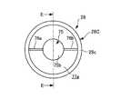
図25、図26において、テールパイプ28の下流部28Cは、拡径されており、下流部28Cの内部には短管75が設けられている。この短管75は、ブラケット76a、76bを介してテールパイプ28の下流部28Cに取付けられている。このため、短管75の軸線方向中心軸は、テールパイプ28の軸線方向中心軸と同一の中心軸となるようにテールパイプ28の中心軸線上に設置されている。 25 and 26, the
また、短管75は、軸線方向他端を構成する上流端に開口端75aを有するとともに、軸線方向一端を構成する下流端に閉口端である底板75bを有し、テールパイプ28の軸線方向に沿って所定長の長さで延在する有底筒状に形成されている。 The
本実施の形態のテールパイプ28は、下流部28Cが中空部材を構成している。この中空部材は、テールパイプ28と一体成形されたものであり、テールパイプ28は、1本のパイプから構成されている。 In the
なお、テールパイプ28の下流部28Cをテールパイプ28と別体の中空部材から構成することにより、中空部材からなる下流部28Cと短管75とによって排気管部品を構成し、この排気管部品をテールパイプ28に後付けするようにしてもよい。 By forming the
また、本実施の形態では、短管75の底板75bが下流開口端28cと同一面上に位置しているため、短管75の底板75bは、テールパイプ28内で発生する気柱共鳴の音圧分布の定在波の節に位置している。なお、短管75の底板75bは、音圧分布の節の位置に対して上流側または下流側に若干ずれていてもよい。 In the present embodiment, since the
また、本実施の形態の短管75は、テールパイプ28内に生じる気柱共鳴の定在波の波長λに対して1/8・λmの長さ、すなわち、テールパイプ28の管長Lの1/4の長さに設定されている。
なお、短管75は、気柱共鳴の定在波の波長λに対して1/8・λm以下の長さ、すなわち、テールパイプ28の管長Lの1/4以下の長さに設定してもよい。Further, the
The
また、本実施の形態では、短管75が設けられるテールパイプ28の下流部28Cの排気通路77aの断面積が、下流部28Cを除いたテールパイプ28の排気通路77の断面積と同じ大きさになるように下流部28Cが拡径されている。なお、下流部28Cの一部は、テーパ形状を有しているため、テーパによって囲まれる排気通路の断面積は除く。 In the present embodiment, the cross-sectional area of the
なお、排気通路77は、テールパイプ28によって囲まれる空間の全てであり、排気通路77の中で短管75の外周部と他端部28Cの内周部とによって囲まれる空間が排気通路77aを構成している。 The
このような構成の短管75を有するテールパイプ28にあっては、テールパイプ28内のポテンシャルエネルギーAを、短管75内のポテンシャルエネルギーA1と、短管75を除いたテールパイプ28内のポテンシャルエネルギーA2とに分散させて、短管75を除いたテールパイプ28内のポテンシャルエネルギーA2のみを外部に放出して、音圧のピークを下げることができ、音圧レベルを低減することができる。 In the
このようにしても、排気騒音を低減することができ、従来用いられていたマフラを廃止するとともにマフラ27を小型化して、排気装置23の重量を低減することができるとともに、排気装置23の製造コストを低減することができる。 Even in this case, the exhaust noise can be reduced, the conventionally used muffler can be eliminated, the
なお、本実施の形態では、短管75が設けられるテールパイプ28の下流部28Cの排気通路77aの断面積が、下流部28Cを除いたテールパイプ28の排気通路77の断面積と同じ大きさになるように下流部28Cが拡径されているが、短管75が設けられるテールパイプ28の下流部28Cの排気通路77aの単位長さ当たりの体積が、下流部28Cを除いたテールパイプ28の排気通路77の単位当たりの体積に対して小さくなるように下流部28Cが拡径されていてもよい。 In the present embodiment, the cross-sectional area of the
この場合には、短管75の大きさを、短管75が取付けられていない状態のテールパイプ28の排気通路77の体積に対して、短管75をテールパイプ28に取付けたときのテールパイプ28の排気通路77の体積の減少量が2.5%以上となるような大きさに設定すればよい。 In this case, the size of the
このようにすれば、テールパイプ28を擬似的に長くして気柱共鳴周波数を管長が長いテールパイプと同等の気柱共鳴周波数に下げることができるとともに、ポテンシャルエネルギーをテールパイプ28の伸び代分だけテールパイプ28全体に分散させてテールパイプ28の内径を擬似的に細くすることができ、気柱共鳴の音圧のピークをさらに低減して気柱共鳴の音圧レベルをさらに低減することができ、第1の実施の形態と同様の効果を得ることができる。 In this way, the
なお、本実施形態では、テールパイプ28の下流部28Cを拡径しているが、上流部28Aを拡径してもよく、上流部28Aと下流部28Cの両方を拡径してもよい。 In the present embodiment, the
(第6の実施の形態)
図27〜図29は、本発明に係る排気管部品および内燃機関の排気装置の第6の実施の形態を示す図であり、第1の実施の形態と同一の構成には同一番号を付して説明を省略する。(Sixth embodiment)
27 to 29 are views showing a sixth embodiment of the exhaust pipe part and the exhaust device of the internal combustion engine according to the present invention. The same reference numerals are given to the same components as those of the first embodiment. The description is omitted.
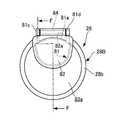
図27〜図29において、テールパイプ28の下流部28Bの内部には短管81が設けられており、この短管81の軸線方向中心軸は、テールパイプ28の軸線方向中心軸に対して上方にずれている。
短管81の一側面は、テールパイプ28の内周面に沿った円部81aが形成されており、円部81aがテールパイプ28の下流部28Bの内周部に溶接等によって固定されている。27 to 29, a
One side surface of the
また、短管81は、軸線方向他端を構成する上流端に開口端81bを有するとともに、軸線方向一端に閉口端および底板を構成する開閉弁82を有し、テールパイプ28の軸線方向に沿って所定長の長さで延在する有底筒状に形成されている。 The
本実施の形態のテールパイプ28は、下流部28Bが中空部材を構成している。この中空部材は、テールパイプ28と一体成形されたものであり、テールパイプ28は、1本のパイプから構成されている。 In the
なお、テールパイプ28の下流部28Bをテールパイプ28と別体の中空部材から構成することにより、中空部材からなる下流部28Bと短管81とによって排気管部品を構成し、この排気管部品をテールパイプ28に後付けするようにしてもよい。 By forming the
また、短管81の開閉弁82は、下流開口端28bと同一面上に位置しており、開閉弁82がテールパイプ28内で発生する気柱共鳴の定在波の音圧分布の節に位置している。 The on-off
また、本実施の形態の短管81は、テールパイプ28内に生じる気柱共鳴の定在波の波長λに対して1/8・λmの長さ、すなわち、テールパイプ28の管長Lの1/4の長さに設定されている。 Further, the
また、テールパイプ28の排気通路83の単位長さ当たりの体積に対して、下流部28Bの排気通路83aの単位長さ当たりの体積が小さくなるように排気通路83aの体積が小さくなっている。 Further, the volume of the
具体的には、短管81は、短管81が取付けられていない状態のテールパイプ28の排気通路83の体積に対して、短管81をテールパイプ28に取付けたときのテールパイプ28の排気通路83の体積の減少量が2.5%以上となるような大きさに設定されている。 Specifically, the
なお、排気通路83は、テールパイプ28によって囲まれる空間の全てであり、排気通路83の中で短管81の外周部と下流部28Bの内周部とによって囲まれる空間が排気通路83aを構成している。 The
一方、短管81の下流端には短管81の幅方向両端部から上方に突出する突出部81c、81dが形成されており、この突出部81c、81dは、一定間隔離隔している。この突出部81c、81dには軸部材84が固定されており、この軸部材84は、開閉弁82の上部に形成された挿通孔82aに挿通されている。 On the other hand, projecting
開閉弁82は、軸部材84に対して揺動自在に取付けられている。この開閉弁82は、短管81内を流れる排気ガスの流量が所定流量以上(例えば、エンジン21が高回転のときの流量)のときに、この排気流を受けて短管81を図29に仮想線で示すように開放し、排気ガスの流量が所定流量未満のときに、短管81を図29に実線で示すように閉塞して短管81の閉口端である底板を構成するようになっている。 The on-off
このような構成の短管81を有するテールパイプ28にあっても、テールパイプ28内のポテンシャルエネルギーAを、短管81内のポテンシャルエネルギーA1と、短管81を除いたテールパイプ28内のポテンシャルエネルギーA2とに分散させて、短管81を除いたテールパイプ28内のポテンシャルエネルギーA2のみを外部に放出して、音圧のピークを下げることができる。 Even in the
また、テールパイプ28を擬似的に長くして気柱共鳴周波数を管長が長いテールパイプと同等の気柱共鳴周波数に下げることができるとともに、ポテンシャルエネルギーをテールパイプ28の伸び代分だけテールパイプ28全体に分散させてテールパイプ28の内径を擬似的に細くすることができ、気柱共鳴の音圧のピークをさらに低減して気柱共鳴の音圧レベルをさらに低減することができる。 In addition, the
この結果、第1の実施の形態と同様に排気騒音を低減することができ、従来用いられていたマフラを廃止するとともにマフラ27を小型化して、排気装置23の重量を低減することができるとともに、排気装置23の製造コストを低減することができる。 As a result, the exhaust noise can be reduced as in the first embodiment, the conventionally used muffler can be eliminated, the
また、本実施の形態では、短管81の閉口端を構成する底板を開閉弁82から構成し、短管81内を流れる排気流の流量が所定流量以上のときに、この排気流を受けて開閉弁82を開放するようにしたので、排気ガスの流量が少ないエンジン21の低回転時に開閉弁82を閉塞させて短管81の底板を構成することができ、短管81内にポテンシャルエネルギーを蓄積することができる。 In the present embodiment, the bottom plate constituting the closed end of the
また、排気ガスの流量が多いときには、開閉弁82を開放させて短管81を通して排気ガスを排出することができるため、エンジン21の高回転時に排気ガスの背圧が上昇するのを防止することができ、排気性能が低下するのを防止することができる。 In addition, when the flow rate of the exhaust gas is large, the on-off
(第7の実施の形態)
図30、図31は、本発明に係る排気管部品および内燃機関の排気装置の第7の実施の形態を示す図であり、第1の実施の形態と同一の構成には同一番号を付して説明を省略する。(Seventh embodiment)
FIGS. 30 and 31 are views showing a seventh embodiment of the exhaust pipe component and the exhaust device of the internal combustion engine according to the present invention. The same components as those in the first embodiment are denoted by the same reference numerals. The description is omitted.
図30、図31において、テールパイプ28の下流部28Bには仕切板91が設けられており、この仕切板91の中心軸は、テールパイプ28の中心軸上に設けられ、下流部28Bの排気通路を上下に区画している。本実施の形態では、この仕切板91と仕切板91の下方に位置するテールパイプ28の下流部28Bの下半分(以下、半円部92という)によって短管93が構成されている。 30 and 31, a
この短管93は、軸線方向他端に開口端93aを有するとともに軸線方向一端に閉口端および底板を構成する開閉弁94を有しており、短管93の軸線方向中心軸は、テールパイプ28の軸線方向中心軸に対して下方にずれている。
また、短管93の開閉弁94は、下流開口端28bと同一面上に位置しており、開閉弁94がテールパイプ28内で発生する気柱共鳴の定在波の音圧分布の節に位置している。The
Further, the on-off
本実施の形態のテールパイプ28は、下流部28Bが中空部材を構成している。この中空部材は、テールパイプ28と一体成形されたものであり、テールパイプ28は、1本のパイプから構成されている。 In the
なお、テールパイプ28の下流部28Bをテールパイプ28と別体の中空部材から構成することにより、中空部材からなる下流部28Bと仕切板91とによって排気管部品を構成し、この排気管部品をテールパイプ28に後付けするようにしてもよい。 By forming the
また、本実施の形態の短管93は、テールパイプ28内に生じる気柱共鳴の定在波の波長λに対して1/8・λmの長さ、すなわち、テールパイプ28の管長Lの1/4の長さに設定されている。 Further, the
また、テールパイプ28の排気通路95の単位長さ当たりの体積に対して、下流部28Bの排気通路95aの単位長さ当たりの体積が小さくなるように排気通路95aの体積が小さくなっている。 Further, the volume of the
具体的には、短管93は、短管93が取付けられていない状態のテールパイプ28の排気通路95の体積に対して、短管93をテールパイプ28に取付けたときのテールパイプ28の排気通路95の体積の減少量が2.5%以上となるような大きさに設定されている。 Specifically, the
なお、排気通路95は、テールパイプ28によって囲まれる空間の全てであり、排気通路95の中で仕切板91と半円部92の内周部とによって囲まれる空間が排気通路95aを構成している。 The
一方、仕切板91の下流端には仕切板91の幅方向両端部から上方に突出する突出部91a、91bが形成されており、この突出部91a、91bは、一定間隔離隔している。この突出部91a、91bには軸部材96が固定されており、この軸部材96は、開閉弁94の上部に形成された挿通孔94aに挿通されている。 On the other hand, projecting
したがって、開閉弁94は、軸部材96に対して揺動自在に取付けられている。この開閉弁94は、短管93内を流れる排気ガスの流量が所定流量以上(例えば、エンジン21が高回転のときの流量)のときに、この排気流を受けて短管93を図31に仮想線で示すように開放し、排気ガスの流量が所定流量未満のときに、短管93を図31に実線で示すように閉塞して短管93の閉口端である底板を構成するようになっている。 Therefore, the on-off
このような構成の短管93を有するテールパイプ28にあっても、テールパイプ28内のポテンシャルエネルギーAを、短管93内のポテンシャルエネルギーA1と、短管93を除いたテールパイプ28内のポテンシャルエネルギーA2とに分散させて、短管93を除いたテールパイプ28内のポテンシャルエネルギーA2のみを外部に放出して、音圧のピークを下げることができる。 Even in the
また、テールパイプ28を擬似的に長くして気柱共鳴周波数を管長が長いテールパイプと同等の気柱共鳴周波数に下げることができるとともに、ポテンシャルエネルギーをテールパイプ28の伸び代分だけテールパイプ28全体に分散させてテールパイプ28の内径を擬似的に細くすることができ、気柱共鳴の音圧のピークをさらに低減して気柱共鳴の音圧レベルをさらに低減することができる。 In addition, the
この結果、第1の実施の形態と同様に排気騒音を低減することができ、従来用いられていたマフラを廃止するとともにマフラ27を小型化して、排気装置23の重量を低減することができるとともに、排気装置23の製造コストを低減することができる。 As a result, the exhaust noise can be reduced as in the first embodiment, the conventionally used muffler can be eliminated, the
また、本実施の形態では、短管93の閉口端を構成する底板を開閉弁94から構成し、短管93内を流れる排気流の流量が所定流量以上のときに、この排気流を受けて開閉弁94を開放するようにしたので、排気ガスの流量が少ないエンジン21の低回転時に開閉弁94を閉塞させて短管93の底板を構成することができ、短管93内にポテンシャルエネルギーを蓄積することができる。 In the present embodiment, the bottom plate constituting the closed end of the
また、排気ガスの流量が多いときには、開閉弁94を開放させて短管93を通して排気ガスを排出することができるため、エンジン21の高回転時に排気ガスの背圧が上昇するのを防止することができ、排気性能が低下するのを防止することができる。 Further, when the flow rate of the exhaust gas is large, the on-off
これに加えて、本実施の形態では、テールパイプ28に単体の短管を取付けるのに代えて、短管93の一部を、テールパイプ28の下流部28Bの一部である半円部92から構成したので、テールパイプ28の軽量化を図ることができる。 In addition, in this embodiment, instead of attaching a single short pipe to the
なお、上記各実施の形態では、短管43、46、61、65、71、75、81、93をテールパイプ28の少なくとも上流部28Aと下流部28Bの何れか一方に設けるようにしているが、気柱共鳴の二次成分f2の音圧分布の節に短管を追加してもよい。 In each of the above embodiments, the
この場合、追加された短管の長さは、テールパイプ28内に生じる気柱共鳴の定在波の波長λに対して1/8・λm以下の長さに設定する。すなわち、二次成分f2の波長λ2は、λ2=Lであるため、短管の長さをテールパイプ28の管長Lの1/8以下の長さに設定し、短管の上流端または下流端が音圧分布の節に位置するようにすればよい。 In this case, the length of the added short tube is set to a length of 1/8 · λm or less with respect to the wavelength λ of the standing column resonance wave generated in the
また、今回開示された実施の形態は、全ての点で例示であってこの実施の形態に制限されるものではない。本発明の範囲は、上記した実施の形態のみの説明ではなくて特許請求の範囲によって示され、特許請求の範囲と均等の意味および範囲内での全ての変更が含まれることが意図される。 The embodiment disclosed this time is illustrative in all respects and is not limited to this embodiment. The scope of the present invention is shown not by the above description of the embodiments but by the scope of the claims, and is intended to include all modifications within the meaning and scope equivalent to the scope of the claims.
以上のように、本発明に係る排気管部品および内燃機関の排気装置は、従来用いられていたマフラを廃止するとともに排気管の一端部に設けられた消音器を小型化して排気騒音を低減することができ、排気装置の重量を低減することができるとともに、排気装置の製造コストを低減することができるという効果を有し、排気ガスの排気方向の最下流に設けられた排気管の気柱共鳴による排気騒音を低減するようにした排気管部品および内燃機関の排気装置等として有用である。 As described above, the exhaust pipe part and the exhaust system for an internal combustion engine according to the present invention eliminate the muffler that has been conventionally used and reduce the size of the silencer provided at one end of the exhaust pipe to reduce the exhaust noise. The exhaust column is provided at the most downstream side in the exhaust direction of the exhaust gas, and the weight of the exhaust device can be reduced and the manufacturing cost of the exhaust device can be reduced. This is useful as an exhaust pipe component that reduces exhaust noise due to resonance, an exhaust system of an internal combustion engine, and the like.
21 エンジン(内燃機関)
23 排気装置
27 マフラ(消音器)
28 テールパイプ(排気管)
28A 上流部(一端部)
28B、28C 下流部(他端部)
28a 上流開口端
28b、28c 下流開口端
41 排気管部品
42b 下流開口端(軸線方向一端)
43、46 短管
43a 開口端
43b 底板(閉口端)
45、45a 排気通路
45a 排気通路
61 短管
61a 底板(閉口端)
61b 環状部材
62、62a 排気通路
65 短管
65a 開口端
65b 底板(閉口端)
67、67a 排気通路
71 短管
71a 開口端
71b 底板(閉口端)
73、73a 排気通路
75 短管
75a 開口端
75b 底板(閉口端)
77、77a 排気通路
81 短管
82 開閉弁(底板、閉口端)
83、83a 排気通路
91 仕切板
93 短管
93a 開口端
94 開閉弁(底板、閉口端)
95、95a 排気通路21 Engine (Internal combustion engine)
23
28 Tail pipe (exhaust pipe)
28A upstream part (one end)
28B, 28C Downstream part (other end part)
28a
43, 46
45,
67,
73,
77,
83,
95, 95a Exhaust passage
【0004】
[0017]
本発明に係る排気管部品は、上記目的を達成するため、(1)一端部に内燃機関から排出された排気ガスの排気方向上流側の消音器に接続される上流開口端を有するとともに、他端部に排気ガスを大気に排出するための下流開口端を有する排気管に取付けられ、前記排気管の一部を構成する排気管部品であって、前記排気管内に生じる気柱共鳴の音圧分布の節を含んだ領域に位置するようにして前記排気管の軸線方向に連接される中空部材と、前記中空部材の内部に設けられ、前記排気管の軸線方向に沿って所定長延在する短管とを備え、前記短管は、軸線方向一端に閉口端を有するとともに軸線方向他端に開口端を有し、前記閉口端が前記排気管内で発生する気柱共鳴の定在波の音圧分布の節と略同位置に位置し、前記短管は、前記気柱共鳴の定在波の波長λに対して1/8・λ以下の長さに設定されるものから構成されている。
[0018]
この構成により、排気管部品を備えた排気管は、気柱共鳴の発生時に、音圧分布の節の位置において、排気管内の気柱共鳴が有するポテンシャルエネルギーを短管内に蓄積して排気管内のポテンシャルエネルギーを短管内と短管を除いた排気管内に分散することができる。
すなわち、気柱共鳴が発生する系が有する力学的エネルギーは、運動エネルギーとポテンシャルエネルギーの和で表され、力学的エネルギーは、保存される。
[0019]
音圧分布の節の位置は、音圧が最小となる反面、粒子速度が最大となるので、排気管内の気柱共鳴が有するポテンシャルエネルギーは、音圧が低い位置に設けられた短管内に蓄積され、このポテンシャルエネルギーは、外部に放出されない。
[0020]
このため、排気管内のポテンシャルエネルギーを、短管内のポテンシャルエネルギーと、短管を除いた排気管内のポテンシャルエネルギーとに分散して、短管を除いた排気管内のポテンシャルエネルギーのみを外部に放出することができる。このため、音圧のピークを下げて音圧レベルを低減することができ、排気騒音を低減することができる。
[0021]
一方、中空部材の内部に、排気管の軸線方向に沿って所定長延在する短管が設けられるので、中空部材の内部の排気通路を絞るようにした場合に、気[0004]
[0017]
In order to achieve the above object, an exhaust pipe component according to the present invention has (1) an upstream opening end connected to a silencer on the upstream side in the exhaust direction of exhaust gas exhausted from an internal combustion engine at one end. An exhaust pipe component which is attached to an exhaust pipe having a downstream opening end for discharging exhaust gas to the atmosphere at an end and forms a part of the exhaust pipe, and which generates sound pressure of air column resonance generated in the exhaust pipe A hollow member connected in the axial direction of the exhaust pipe so as to be located in a region including the distribution nodes, and a short member provided inside the hollow member and extending a predetermined length along the axial direction of the exhaust pipe The short pipe has a closed end at one end in the axial direction and an open end at the other end in the axial direction, and the closed end has a sound pressure of standing wave of air column resonance generated in the exhaust pipe. The short pipe is located at the same position as the distribution node, and the air column And a shall be set to 1/8 · lambda less in length to the wavelength lambda of the standing wave.
[0018]
With this configuration, the exhaust pipe having the exhaust pipe components accumulates the potential energy of the air column resonance in the exhaust pipe in the position of the sound pressure distribution at the position of the sound pressure distribution at the time of occurrence of the air column resonance. Potential energy can be dispersed in the short pipe and in the exhaust pipe excluding the short pipe.
That is, the mechanical energy possessed by the system in which air column resonance occurs is represented by the sum of kinetic energy and potential energy, and the mechanical energy is preserved.
[0019]
The position of the nodes in the sound pressure distribution minimizes the sound pressure, but maximizes the particle velocity, so the potential energy of the air column resonance in the exhaust pipe accumulates in the short pipe provided at the position where the sound pressure is low. This potential energy is not released to the outside.
[0020]
Therefore, the potential energy in the exhaust pipe is dispersed into the potential energy in the short pipe and the potential energy in the exhaust pipe excluding the short pipe, and only the potential energy in the exhaust pipe excluding the short pipe is released to the outside. Can do. For this reason, the sound pressure level can be reduced by lowering the peak of the sound pressure, and the exhaust noise can be reduced.
[0021]
On the other hand, since a short pipe extending a predetermined length along the axial direction of the exhaust pipe is provided inside the hollow member, when the exhaust passage inside the hollow member is throttled, the air
【0005】
柱共鳴の定在波の粒子速度が最大となる音圧分布の節の位置において、粒子速度を上昇させることができる。
[0022]
排気管内の気柱共鳴が持つポテンシャルエネルギーは、排気管内のポテンシャルエネルギーと短管内のポテンシャルエネルギーに分散されているが、ポテンシャルエネルギーは、全体として変化がないのに対して、運動エネルギーを飛躍的に増大させることができるため、力学的エネルギーを増加させることができる。このため、排気管を擬似的に長くすることができ、気柱共鳴周波数を管長が長い排気管と同等の気柱共鳴周波数に下げることができる。
[0023]
また、排気管が擬似的に長くなると、短管の内部に蓄積していたポテンシャルエネルギーを除いた排気管内のポテンシャルエネルギーは、排気管の伸び代分だけ排気管全体に分散されるため、力学的エネルギーの観点からは、排気管の内径が細くなったものと等価となり、気柱共鳴の音圧のピークをさらに低減して気柱共鳴の音圧レベルをさらに低減することができる。
[0024]
この結果、排気騒音を大幅に低減することができ、排気管部品を排気管と消音器とを備えた排気装置に設けた場合に、従来用いられていたマフラを廃止するとともに排気管の一端部に設けられた消音器を小型化して排気騒音を低減することができ、排気装置の重量を低減することができるとともに、排気装置の製造コストを低減することができる。
特に、短管を、気柱共鳴の定在波の波長λに対して1/8・λ以下の長さに設定したので、短管を気柱共鳴の定在波の粒子速度が大きい位置に短管を位置させることができ、ポテンシャルエネルギーの減少量に対して排気管内の排気ガスの運動エネルギーをより効果的に大きくすることができる。
[0025]
また、本発明に係る排気管部品は、上記目的を達成するため、(2)一端部に内燃機関から排出された排気ガスの排気方向上流側の消音器に接続される上流開口端を有するとともに、他端部に排気ガスを大気に排出するための下流開口端を有する排気管に取付けられ、前記排気管の一部を構成する排気管部品であって、前記排気管内に生じる気柱共鳴の音圧分布の節を含んだ領域に位置するようにして前記排気管の軸線方向に連接される中空部材と、前記中空部材の内部に設けられ、前記排気管の軸線方向に沿って所定長延在する短管とを備え、前記短管は、軸線方向一端に閉口端を有するとともに軸線方向他端に開口端を有し、前記閉口端が前記排気管内で発生する気柱共鳴の定在波の音圧分布の節と略同位置に位置し、前記短管は、前記排気管の長さの1/4以下の長さに設定されるものから構成されている。このようにしても上述した排気管部品と同一の作用効果を得ることができる。
本発明では、特に、排気管の長さの1/4以下の長さに設定したので、短管を気柱共鳴の定在波の粒子速度が大きい位置に短管を位置させることができ、ポテンシャルエネルギーの減少量に対して排気管内の排気ガスの運動エネルギーをより効果的に大きくすることができる。
上記(1)または(2)に記載の排気管部品において、(3)前記排気管の排気通路の単位長さ当たりの体積に対して前記中空部材の排気通路の単位長さ当たりの体積が小さくなるように、前記短管と前記中空部材の間の排気通路が絞られるものから構成されている。
[0026]
この構成により、排気管部品を備えた排気管は、気柱共鳴の定在波の粒子速度が最大となる音圧分布の節の位置において、粒子速度を上昇させることができ、排気管全体のポテンシャルエネルギーに対して運動エネルギーを飛躍的に増大させることができる。このため、力学的エネルギーを増加させて、排気管を擬似的に長くすることができ、気柱共鳴周波数を管長が長い排気[0005]
The particle velocity can be increased at the position of the node of the sound pressure distribution where the particle velocity of the standing wave of the column resonance is maximized.
[0022]
The potential energy of the air column resonance in the exhaust pipe is distributed between the potential energy in the exhaust pipe and the potential energy in the short pipe, but the potential energy does not change as a whole, while the kinetic energy is dramatically increased. Since it can be increased, the mechanical energy can be increased. For this reason, the exhaust pipe can be made pseudo-long, and the air column resonance frequency can be lowered to an air column resonance frequency equivalent to that of the exhaust pipe having a long tube length.
[0023]
In addition, when the exhaust pipe becomes pseudo-long, the potential energy in the exhaust pipe, excluding the potential energy accumulated inside the short pipe, is dispersed throughout the exhaust pipe by the amount of expansion of the exhaust pipe. From an energy point of view, this is equivalent to a case where the inner diameter of the exhaust pipe is reduced, and the sound pressure level of the air column resonance can be further reduced by further reducing the sound pressure peak of the air column resonance.
[0024]
As a result, exhaust noise can be greatly reduced, and when an exhaust pipe component is provided in an exhaust system equipped with an exhaust pipe and a silencer, the conventionally used muffler is eliminated and one end of the exhaust pipe is removed. It is possible to reduce the exhaust noise by reducing the size of the silencer provided in the exhaust device, to reduce the weight of the exhaust device, and to reduce the manufacturing cost of the exhaust device.
In particular, since the short tube is set to a length of 1/8 · λ or less with respect to the wavelength λ of the standing wave of the air column resonance, the short tube is placed at a position where the particle velocity of the standing wave of the air column resonance is large. The short pipe can be positioned, and the kinetic energy of the exhaust gas in the exhaust pipe can be increased more effectively with respect to the amount of decrease in potential energy.
[0025]
In order to achieve the above object, the exhaust pipe component according to the present invention has (2) an upstream opening end connected to a silencer on the upstream side in the exhaust direction of the exhaust gas discharged from the internal combustion engine at one end. An exhaust pipe component which is attached to an exhaust pipe having a downstream opening end for discharging exhaust gas to the atmosphere at the other end and constitutes a part of the exhaust pipe, A hollow member connected in the axial direction of the exhaust pipe so as to be located in a region including a node of the sound pressure distribution, and provided inside the hollow member and extending a predetermined length along the axial direction of the exhaust pipe The short pipe has a closed end at one end in the axial direction and an open end at the other end in the axial direction, and the closed end of the standing wave of air column resonance generated in the exhaust pipe Located at the same position as the nodes of the sound pressure distribution, the short pipe is And an shall be set to 1/4 or less of the length of the length of the trachea. Even if it does in this way, the same effect as the exhaust pipe component mentioned above can be acquired.
In the present invention, in particular, since the length of the exhaust pipe is set to 1/4 or less, the short pipe can be positioned at a position where the particle velocity of the standing wave of air column resonance is large, The kinetic energy of the exhaust gas in the exhaust pipe can be increased more effectively with respect to the decrease amount of the potential energy.
In the exhaust pipe component according to the above (1) or (2), (3) the volume per unit length of the exhaust passage of the hollow member is smaller than the volume per unit length of the exhaust passage of the exhaust pipe. In this way, the exhaust passage between the short pipe and the hollow member is restricted.
[0026]
With this configuration, the exhaust pipe having the exhaust pipe components can increase the particle velocity at the position of the node of the sound pressure distribution where the particle velocity of the standing wave of air column resonance is maximized. The kinetic energy can be dramatically increased with respect to the potential energy. For this reason, the mechanical energy can be increased and the exhaust pipe can be made longer in a pseudo manner, and the air column resonance frequency can be increased with the longer pipe length.
【0006】
管と同等の気柱共鳴周波数に下げることができる。
[0027]
また、排気管が擬似的に長くなると、短管の内部に蓄積していたポテンシャルエネルギーを除いた排気管内のポテンシャルエネルギーは、排気管の伸び代分だけ排気管全体に分散されるため、力学的エネルギーの観点からは、排気管の内径が細くなったものと等価となり、気柱共鳴の音圧のピークを低減することができる。
[0028]
上記(1)ないし(3)に記載の排気管部品において、(4)前記中空部材は、前記排気管の内径と略同一の内径を有するものから構成されている。
この排気管部品を備えた排気管は、排気管の内径と略同一の内径を有する中空部材が排気管に取付けられるので、すなわち、直管に、短管を有する排気管部品が取付けられるので、排気管の排気通路の単位長さ当たりの体積に対して中空部材の排気通路の単位長さ当たりの体積を小さくして短管と中空部材の間の排気通路を絞ることができ、粒子速度が最大となる音圧分布の節で粒子速度を上昇させることができる。
[0029]
上記(1)ないし(4)に記載の排気管部品において、(5)前記中空部材は、前記中空部材の軸線方向一端が、前記排気管の前記上流開口端および前記下流開口端の少なくとも一方を構成するように、前記排気管の前記一端部および前記他端部の少なくとも一方に設けられるものから構成されている。
[0030]
この構成により、排気管部品を備えた排気管は、気柱共鳴の定在波の音圧分布の節となる排気管の上流開口端または下流開口端を構成するように排気管の一端部または他端部を排気管部品から構成すれば、気柱共鳴の音圧のピークが最も大きい一次成分の音圧のピークを確実に低減することができるとともに、一次成分の気柱共鳴周波数を管長が長い排気管と同等の気柱共鳴周波数に下げることができる。この結果、排気騒音をより一層低減することができる。
[0031]
これに加えて、気柱共鳴の一次成分を基本とした二次成分以上の音圧のピークも低減することができるため、内燃機関の常用回転域において排気騒音[0006]
The air column resonance frequency can be lowered to the same level as the tube.
[0027]
In addition, when the exhaust pipe becomes pseudo-long, the potential energy in the exhaust pipe, excluding the potential energy accumulated inside the short pipe, is dispersed throughout the exhaust pipe by the amount of expansion of the exhaust pipe. From the standpoint of energy, this is equivalent to the exhaust pipe having a narrow inner diameter, and the sound pressure peak of air column resonance can be reduced.
[0028]
In the exhaust pipe component according to the above (1) to (3), (4) the hollow member is configured to have an inner diameter substantially the same as the inner diameter of the exhaust pipe.
Since the exhaust pipe provided with this exhaust pipe part has a hollow member having an inner diameter substantially the same as the inner diameter of the exhaust pipe attached to the exhaust pipe, that is, the exhaust pipe part having a short pipe is attached to the straight pipe. By reducing the volume per unit length of the exhaust passage of the hollow member relative to the volume per unit length of the exhaust passage of the exhaust pipe, the exhaust passage between the short pipe and the hollow member can be throttled, and the particle velocity can be reduced. The particle velocity can be increased at the node of the maximum sound pressure distribution.
[0029]
In the exhaust pipe component according to the above (1) to (4), (5) the hollow member has at least one of the upstream opening end and the downstream opening end of the exhaust pipe at one end in the axial direction of the hollow member. As comprised, it is comprised from what is provided in at least one of the said one end part and the said other end part of the said exhaust pipe.
[0030]
With this configuration, the exhaust pipe provided with the exhaust pipe component is configured so that one end of the exhaust pipe or the downstream open end of the exhaust pipe that constitutes a node of the sound pressure distribution of the standing wave of air column resonance constitutes one end of the exhaust pipe or If the other end portion is composed of an exhaust pipe component, the peak of the sound pressure of the primary component having the largest sound pressure peak of the air column resonance can be reliably reduced, and the air column resonance frequency of the primary component can be reduced by the tube length. The air column resonance frequency can be reduced to the same level as a long exhaust pipe. As a result, exhaust noise can be further reduced.
[0031]
In addition to this, it is possible to reduce the peak of the sound pressure higher than the secondary component based on the primary component of the air column resonance.
【0007】
をより一層低減することができる。
[0032]
上記(1)ないし(5)に記載の排気管部品において、(6)前記短管が設けられていない場合の前記排気管の排気通路全体の体積に対して、前記短管が設けられた前記中空部材および前記排気管の排気通路全体の体積減少量が2.5%以上となるように前記短管の大きさが設定されるものから構成されている。
[0033]
この構成により、排気管部品を備えた排気管は、排気管の排気通路全体の体積減少量が2.5%以上となるように短管の大きさが設定された排気管を用いてスピーカ加振試験を行った結果、気柱共鳴周波数を管長が長い排気管と同等の気柱共鳴周波数に下げることができるとともに、音圧のピークを低減できることが確認された。
[0034]
[0035]
[0036]
上記(1)ないし(6)に記載の排気管部品において、(7)前記短管が、前記中空部材の軸線方向一端から前記排気管の中心軸に向かって折り曲げられた閉口端と、前記閉口端から前記中空部材の軸線方向他端に向かって折り曲げられて前記中空部材と平行に延在する環状部材とを備えたものから構成されている。
[0037]
この構成により、排気管部品を備えた排気管は、中空部材の軸線方向一端部を折り曲げることで短管を容易に成形することができ、中空部材の製造コストを低減することができ、結果的に排気管の製造コストを低減することができる。
[0038]
上記(1)ないし(7)に記載の排気管部品において、(8)前記中空部[0007]
Can be further reduced.
[0032]
In the exhaust pipe component according to the above (1) to (5), (6) the short pipe is provided with respect to the entire volume of the exhaust pipe when the short pipe is not provided. The size of the short pipe is set so that the volume reduction amount of the hollow member and the whole exhaust passage of the exhaust pipe is 2.5% or more.
[0033]
With this configuration, the exhaust pipe provided with the exhaust pipe parts is connected to the speaker by using the exhaust pipe whose size is set to 2.5% or more so that the volume reduction amount of the entire exhaust passage of the exhaust pipe is 2.5% or more. As a result of the vibration test, it was confirmed that the air column resonance frequency can be lowered to an air column resonance frequency equivalent to that of an exhaust pipe having a long tube length, and the peak of sound pressure can be reduced.
[0034]
[0035]
[0036]
In the exhaust pipe component according to the above (1) to (6), (7) a closed end where the short pipe is bent from one axial end of the hollow member toward a central axis of the exhaust pipe, and the closed pipe It is comprised from what was bent toward the axial direction other end of the said hollow member from the end, and the annular member extended in parallel with the said hollow member.
[0037]
With this configuration, the exhaust pipe provided with the exhaust pipe parts can be easily formed into a short pipe by bending one end of the hollow member in the axial direction, thereby reducing the manufacturing cost of the hollow member. In addition, the manufacturing cost of the exhaust pipe can be reduced.
[0038]
In the exhaust pipe component according to the above (1) to (7), (8) the hollow portion
【0018】
テールパイプ28の管長Lの略2倍となり、二次成分の気柱共鳴の波長λ2は、管長Lの略1倍となる。
[0083]
図6から明らかなように、それぞれの定在波は、テールパイプ28の上流開口端28aおよび下流開口端28bが粒子速度の腹となり、この粒子速度は、上流開口端28aおよび下流開口端28bで最大となる。
[0084]
また、一次成分および二次成分の気柱共鳴の定在波の音圧分布は、図7に示すように、粒子速度分布の腹と節とがそれぞれ逆となってテールパイプ28の上流開口端28aおよび下流開口端28bが音圧分布の節となり、音圧は、上流開口端28aおよび下流開口端28bで最小となる。
[0085]
また、短管43は、テールパイプ28内に生じる気柱共鳴の定在波の波長λに対して1/8・λ以下の長さに設定されている。本実施の形態では、短管43がテールパイプ28の下流部28Bに設けられており、図6に示すように、λ1=2Lであるため、短管43の長さは、テールパイプ28の管長Lの1/4の長さに設定されている。
なお、短管43は、気柱共鳴の定在波の波長λに対して1/8・λ以下の長さ、すなわち、テールパイプ28の管長Lの1/4以下の長さに設定してもよい。
[0086]
また、本実施の形態では、同一の内径を有する直管のテールパイプ28の下流部28Bに軸線方向に沿ってテールパイプ28の管長Lの1/4の長さで延在する短管43が設けられるため、テールパイプ28の排気通路45の単位長さ当たりの体積に対して下流部28Bの排気通路45aの単位長さ当たりの体積が小さくなるように、短管43と下流部28Bの間の排気通路45の体積が小さくなっている。
[0087]
このため、図6、図7に示すように、気柱共鳴の定在波の音圧分布の節において気柱共鳴の粒子速度が最大となることを利用して、テールパイプ28の下流部28Bの単位長さ当たり体積を小さくすることにより、テールパイプ28の下流部28Bの気柱共鳴の粒子速度を上昇させることができる。
[0088]
また、短管43は、短管43が取付けられていない状態のテールパイプ2[0018]
The tube length L of the
[0083]
As is clear from FIG. 6, each standing wave has antinodes of the particle velocity at the upstream opening
[0084]
Further, as shown in FIG. 7, the sound pressure distribution of the standing wave of the air column resonance of the primary component and the secondary component is such that the antinodes and nodes of the particle velocity distribution are reversed, and the upstream opening end of the
[0085]
The
The
[0086]
In the present embodiment, a
[0087]
Therefore, as shown in FIGS. 6 and 7, the
[0088]
Further, the
【0030】
気柱共鳴の一次成分f1と一次成分の倍音である気柱共鳴の二次成分f2の音圧のピークを点線で示す位置から実線で示す位置に低減することができるため、排気騒音を大幅に低減することができる。
[0146]
したがって、従来用いられていたマフラを廃止することができるとともに、大容量の共鳴室36を不要にしてマフラ27を小型化することができる。このため、排気装置23の重量を低減することができるとともに、排気装置23の製造コストを低減することができる。
[0147]
また、本実施の形態では、短管43を、テールパイプ28内に生じる気柱共鳴の定在波の波長λに対して1/8・λの長さに設定し、短管43の底板43bを、テールパイプ28内に生じる気柱共鳴の定在波の音圧分布の節に位置させたので、短管43を気柱共鳴の定在波の粒子速度が大きい位置に位置させることができ、ポテンシャルエネルギーの減少量に対してテールパイプ28内の排気ガスの運動エネルギーをより効果的に大きくすることができる。
[0148]
これに対して、短管43を気柱共鳴の定在波の波長λに対して1/8・λを越える長さに設定すると、ポテンシャルエネルギーが大きく粒子速度の小さい位置に短管43の一部が位置してしまうことになるので、テールパイプ28内のポテンシャルエネルギーの減少量に対してテールパイプ28内の運動エネルギーの増加量を大きくすることができないため、結果的に、テールパイプ28内の力学的エネルギーが減少してしまう。
[0149]
このため、テールパイプ28が擬似的に短くなって、気柱共鳴周波数を上げてしまうことになるので、好ましくない。したがって、短管43の長さは、気柱共鳴の定在波の波長λに対して1/8・λ以下の長さに設定するのが好ましい。
[0150]
なお、本実施の形態では、テールパイプ28をパイプ本体40と排気管部品41とから構成しているが、テールパイプを、パイプ本体40と排気管部品41が一体成形された1本のテールパイプから構成してもよい。このようにすれば、パイプ本体40と排気管部品41を別々に製造してパイプ本体4[0030]
Since the peak of the sound pressure of the primary component f1 of the air column resonance and the secondary component f2 of the air column resonance that is a harmonic of the primary component can be reduced from the position indicated by the dotted line to the position indicated by the solid line, the exhaust noise is greatly increased. Can be reduced.
[0146]
Therefore, the conventionally used muffler can be eliminated, and the
[0147]
Further, in the present embodiment, the
[0148]
On the other hand, when the
[0149]
For this reason, the
[0150]
In the present embodiment, the
【0032】
[0156]
(第2の実施の形態)
図18、図19は、本発明に係る排気管部品および内燃機関の排気装置の第2の実施の形態を示す図であり、第1の実施の形態と同一の構成には同一番号を付して説明を省略する。
[0157]
図18、図19において、短管61は、テールパイプ28の下流部28Bの下流開口端28bからテールパイプ28の中心軸Cに向かって折り曲げられた閉口端である底板61aと、底板61aからテールパイプ28の上流開口端28aに向かって折り曲げられてテールパイプ28と平行に延在し、上流端においてテールパイプ28の下流部28Bと共に開口端61cを構成する環状部材61bとを備えている。したがって、短管61は、下流部28Bと一体の有底筒状に形成されている。
[0158]
本実施の形態のテールパイプ28は、下流部28Bが中空部材を構成している。中空部材および短管61は、テールパイプ28と一体成形されたものであり、テールパイプ28は、1本のパイプから構成されている。
[0159]
なお、テールパイプ28の下流部28Bをテールパイプ28と別体の中空部材から構成することにより、中空部材からなる下流部28Bと短管61とによって排気管部品を構成し、この排気管部品をテールパイプ28に後付けするようにしてもよい。
[0160]
すなわち、下流部28Bを排気管部品から構成する場合には、下流部28Bをテールパイプ28から取り外した状態において、下流部28Bの軸線方向一端からテールパイプ28の中心軸Cに向かって折り曲げられた閉口端である底板61aと、底板61aから下流部28Bの軸線方向他端に向かって折り曲げられて下流部28Bと平行に延在する環状部材61bを備えたものとなる。
[0161]
一方、短管61の軸線方向一端である底板61aは、下流開口端28bと同一面上に位置しており、短管61の環状部材61bは、底板61aから上流開口端28aに向かって延在している。本実施の形態の短管61は、テールパイプ28内に生じる気柱共鳴の定在波の波長λに対して1/8・λの[0032]
[0156]
(Second Embodiment)
18 and 19 are views showing a second embodiment of an exhaust pipe component and an exhaust device for an internal combustion engine according to the present invention. The same components as those in the first embodiment are denoted by the same reference numerals. The description is omitted.
[0157]
18 and 19, a
[0158]
In the
[0159]
By forming the
[0160]
That is, when the
[0161]
On the other hand, the
【0033】
長さ、すなわち、テールパイプ28の管長Lの1/4の長さに設定されている。
[0162]
なお、短管61は、気柱共鳴の定在波の波長λに対して1/8・λ以下の長さ、すなわち、テールパイプ28の管長Lの1/4以下の長さに設定してもよい。
[0163]
また、本実施の形態では、短管61の底板61aが下流開口端28bと同一面上に位置しているため、短管61の底板61aは、テールパイプ28内で発生する気柱共鳴の音圧分布の定在波の節に位置している。なお、短管61の底板61aは、音圧分布の節の位置に対して上流側または下流側に若干ずれていてもよい。
[0164]
また、テールパイプ28の排気通路62の単位長さ当たりの体積に対して、下流部28Bの排気通路62aの単位長さ当たりの体積が小さくなるように排気通路62aの体積が小さくなっている。
[0165]
具体的には、短管61は、短管61が取付けられていない状態のテールパイプ28の排気通路62の体積に対して、短管61をテールパイプ28に取付けたときのテールパイプ28の排気通路62の体積の減少量が2.5%以上となるような大きさに設定されている。
[0166]
また、排気通路62は、テールパイプ28によって囲まれる空間の全てであり、排気通路62の中で環状部材61bの内周部によって囲まれる空間が排気通路62aを構成している。
[0167]
このような構成の短管61を有するテールパイプ28にあっても、テールパイプ28内のポテンシャルエネルギーAを、短管61内のポテンシャルエネルギーA1と、短管61を除いたテールパイプ28内のポテンシャルエネルギーA2とに分散させて、短管61を除いたテールパイプ28内のポテンシャルエネルギーA2のみを外部に放出して、音圧のピークを下げることができる。
[0168]
また、テールパイプ28を擬似的に長くして気柱共鳴周波数を管長が長いテールパイプと同等の気柱共鳴周波数に下げることができるとともに、ポテ[0033]
The length is set to ¼ of the pipe length L of the
[0162]
The
[0163]
In the present embodiment, since the
[0164]
Further, the volume of the
[0165]
Specifically, the
[0166]
The
[0167]
Even in the
[0168]
In addition, the
【0035】
してテールパイプ28の上流部28Aに取付けられている。このため、短管65の軸線方向中心軸は、テールパイプ28の軸線方向中心軸と同一の中心軸となるようにテールパイプ28の中心軸線上に設置されている。
[0175]
また、短管65は、軸線方向他端を構成する下流端に開口端65aを有するとともに、軸線方向一端を構成する上流端に閉口端である底板65bを有し、テールパイプ28の軸線方向に沿って所定長の長さで延在する有底筒状に形成されている。
[0176]
また、短管65の底板65bは、球面または放物面に形成されており、短管65は、底板65b側の断面積が、開口端65a側の断面積よりも小さく形成されている。
[0177]
本実施の形態のテールパイプ28は、上流部28Aが中空部材を構成している。この中空部材は、テールパイプ28と一体成形されたものであり、テールパイプ28は、1本のパイプから構成されている。
[0178]
なお、テールパイプ28の上流部28Aをテールパイプ28と別体の中空部材から構成することにより、中空部材からなる上流部28Aと短管65とによって排気管部品を構成し、この排気管部品をテールパイプ28に後付けするようにしてもよい。
[0179]
また、本実施の形態では、短管65の底板65bが上流開口端28aと同一面上に位置しているため、短管65の底板65bは、テールパイプ28内で発生する気柱共鳴の音圧分布の定在波の節に位置している。なお、短管65の底板65bは、音圧分布の節の位置に対して上流側または下流側に若干ずれていてもよい。
[0180]
また、本実施の形態の短管65は、テールパイプ28内に生じる気柱共鳴の定在波の波長λに対して1/8・λの長さ、すなわち、テールパイプ28の管長Lの1/4の長さに設定されている。
なお、短管65は、気柱共鳴の定在波の波長λに対して1/8・λ以下の長さ、すなわち、テールパイプ28の管長Lの1/4以下の長さに設定してもよい。[0035]
The
[0175]
The
[0176]
Further, the
[0177]
In the
[0178]
By configuring the
[0179]
In the present embodiment, since the
[0180]
Further, the
The
【0038】
するようにしてもよい。
[0194]
また、本実施の形態では、短管71の底板71bが下流開口端28bと同一面上に位置しているため、短管71の底板71bは、テールパイプ28内で発生する気柱共鳴の音圧分布の定在波の節に位置している。なお、短管71の底板71bは、音圧分布の節の位置に対して上流側または下流側に若干ずれていてもよい。
[0195]
また、本実施の形態の短管71は、テールパイプ28内に生じる気柱共鳴の定在波の波長λに対して1/8・λの長さ、すなわち、テールパイプ28の管長Lの1/4の長さに設定されている。
なお、短管71は、気柱共鳴の定在波の波長λに対して1/8・λ以下の長さ、すなわち、テールパイプ28の管長Lの1/4以下の長さに設定してもよい。
[0196]
本実施の形態では、短管71が設けられるテールパイプ28の下流部28Bの排気通路73aの単位長さ当たりの体積は、下流部28Bを除いたテールパイプ28の排気通路73の単位当たりの体積に対して小さくなっている。
[0197]
具体的には、短管71は、短管71が取付けられていない状態のテールパイプ28の排気通路73の体積に対して、短管71をテールパイプ28に取付けたときのテールパイプ28の排気通路73の体積の減少量が2.5%以上となるような大きさに設定されている。
[0198]
また、排気通路73は、テールパイプ28によって囲まれる空間の全てであり、排気通路73の中で短管71の外周部と下流部28Bの内周部とによって囲まれる空間が排気通路73aを構成している。
[0199]
このような構成の短管71を有するテールパイプ28にあっても、テールパイプ28内のポテンシャルエネルギーAを、短管71内のポテンシャルエネルギーA1と、短管71を除いたテールパイプ28内のポテンシャルエネルギーA2とに分散させて、短管71を除いたテールパイプ28内のポテンシャルエネルギーA2のみを外部に放出して、音圧のピークを下げることが[0038]
You may make it do.
[0194]
In the present embodiment, since the
[0195]
Further, the
The
[0196]
In the present embodiment, the volume per unit length of the
[0197]
Specifically, the
[0198]
The
[0199]
Even in the
【0040】
るとともに、軸線方向一端を構成する下流端に閉口端である底板75bを有し、テールパイプ28の軸線方向に沿って所定長の長さで延在する有底筒状に形成されている。
[0206]
本実施の形態のテールパイプ28は、下流部28Cが中空部材を構成している。この中空部材は、テールパイプ28と一体成形されたものであり、テールパイプ28は、1本のパイプから構成されている。
[0207]
なお、テールパイプ28の下流部28Cをテールパイプ28と別体の中空部材から構成することにより、中空部材からなる下流部28Cと短管75とによって排気管部品を構成し、この排気管部品をテールパイプ28に後付けするようにしてもよい。
[0208]
また、本実施の形態では、短管75の底板75bが下流開口端28cと同一面上に位置しているため、短管75の底板75bは、テールパイプ28内で発生する気柱共鳴の音圧分布の定在波の節に位置している。なお、短管75の底板75bは、音圧分布の節の位置に対して上流側または下流側に若干ずれていてもよい。
[0209]
また、本実施の形態の短管75は、テールパイプ28内に生じる気柱共鳴の定在波の波長λに対して1/8・λの長さ、すなわち、テールパイプ28の管長Lの1/4の長さに設定されている。
なお、短管75は、気柱共鳴の定在波の波長λに対して1/8・λ以下の長さ、すなわち、テールパイプ28の管長Lの1/4以下の長さに設定してもよい。
[0210]
また、本実施の形態では、短管75が設けられるテールパイプ28の下流部28Cの排気通路77aの断面積が、下流部28Cを除いたテールパイプ28の排気通路77の断面積と同じ大きさになるように下流部28Cが拡径されている。なお、下流部28Cの一部は、テーパ形状を有しているため、テーパによって囲まれる排気通路の断面積は除く。
[0211]
なお、排気通路77は、テールパイプ28によって囲まれる空間の全てであり、排気通路77の中で短管75の外周部と他端部28Cの内周部とによ[0040]
In addition, a
[0206]
In the
[0207]
By forming the
[0208]
In the present embodiment, since the
[0209]
Further, the
The
[0210]
In the present embodiment, the cross-sectional area of the
[0211]
The
【0043】
[0224]
また、本実施の形態の短管81は、テールパイプ28内に生じる気柱共鳴の定在波の波長λに対して1/8・λの長さ、すなわち、テールパイプ28の管長Lの1/4の長さに設定されている。
[0225]
また、テールパイプ28の排気通路83の単位長さ当たりの体積に対して、下流部28Bの排気通路83aの単位長さ当たりの体積が小さくなるように排気通路83aの体積が小さくなっている。
[0226]
具体的には、短管81は、短管81が取付けられていない状態のテールパイプ28の排気通路83の体積に対して、短管81をテールパイプ28に取付けたときのテールパイプ28の排気通路83の体積の減少量が2.5%以上となるような大きさに設定されている。
[0227]
なお、排気通路83は、テールパイプ28によって囲まれる空間の全てであり、排気通路83の中で短管81の外周部と下流部28Bの内周部とによって囲まれる空間が排気通路83aを構成している。
[0228]
一方、短管81の下流端には短管81の幅方向両端部から上方に突出する突出部81c、81dが形成されており、この突出部81c、81dは、一定間隔離隔している。この突出部81c、81dには軸部材84が固定されており、この軸部材84は、開閉弁82の上部に形成された挿通孔82aに挿通されている。
[0229]
開閉弁82は、軸部材84に対して揺動自在に取付けられている。この開閉弁82は、短管81内を流れる排気ガスの流量が所定流量以上(例えば、エンジン21が高回転のときの流量)のときに、この排気流を受けて短管81を図29に仮想線で示すように開放し、排気ガスの流量が所定流量未満のときに、短管81を図29に実線で示すように閉塞して短管81の閉口端である底板を構成するようになっている。
[0230]
このような構成の短管81を有するテールパイプ28にあっても、テールパイプ28内のポテンシャルエネルギーAを、短管81内のポテンシャルエネルギーA1と、短管81を除いたテールパイプ28内のポテンシャルエネルギーA2とに分散させて、短管81を除いたテールパイプ28内のポテン[0043]
[0224]
Further, the
[0225]
Further, the volume of the
[0226]
Specifically, the
[0227]
The
[0228]
On the other hand, projecting
[0229]
The on-off
[0230]
Even in the
【0045】
軸上に設けられ、下流部28Bの排気通路を上下に区画している。本実施の形態では、この仕切板91と仕切板91の下方に位置するテールパイプ28の下流部28Bの下半分(以下、半円部92という)によって短管93が構成されている。
[0237]
この短管93は、軸線方向他端に開口端93aを有するとともに軸線方向一端に閉口端および底板を構成する開閉弁94を有しており、短管93の軸線方向中心軸は、テールパイプ28の軸線方向中心軸に対して下方にずれている。
また、短管93の開閉弁94は、下流開口端28bと同一面上に位置しており、開閉弁94がテールパイプ28内で発生する気柱共鳴の定在波の音圧分布の節に位置している。
[0238]
本実施の形態のテールパイプ28は、下流部28Bが中空部材を構成している。この中空部材は、テールパイプ28と一体成形されたものであり、テールパイプ28は、1本のパイプから構成されている。
[0239]
なお、テールパイプ28の下流部28Bをテールパイプ28と別体の中空部材から構成することにより、中空部材からなる下流部28Bと仕切板91とによって排気管部品を構成し、この排気管部品をテールパイプ28に後付けするようにしてもよい。
[0240]
また、本実施の形態の短管93は、テールパイプ28内に生じる気柱共鳴の定在波の波長λに対して1/8・λの長さ、すなわち、テールパイプ28の管長Lの1/4の長さに設定されている。
[0241]
また、テールパイプ28の排気通路95の単位長さ当たりの体積に対して、下流部28Bの排気通路95aの単位長さ当たりの体積が小さくなるように排気通路95aの体積が小さくなっている。
[0242]
具体的には、短管93は、短管93が取付けられていない状態のテールパイプ28の排気通路95の体積に対して、短管93をテールパイプ28に取付けたときのテールパイプ28の排気通路95の体積の減少量が2.5%以上となるような大きさに設定されている。[0045]
Provided on the shaft, the exhaust passage of the
[0237]
The
Further, the on-off
[0238]
In the
[0239]
By forming the
[0240]
Further, the
[0241]
Further, the volume of the
[0242]
Specifically, the
【0047】
装置23の重量を低減することができるとともに、排気装置23の製造コストを低減することができる。
[0249]
また、本実施の形態では、短管93の閉口端を構成する底板を開閉弁94から構成し、短管93内を流れる排気流の流量が所定流量以上のときに、この排気流を受けて開閉弁94を開放するようにしたので、排気ガスの流量が少ないエンジン21の低回転時に開閉弁94を閉塞させて短管93の底板を構成することができ、短管93内にポテンシャルエネルギーを蓄積することができる。
[0250]
また、排気ガスの流量が多いときには、開閉弁94を開放させて短管93を通して排気ガスを排出することができるため、エンジン21の高回転時に排気ガスの背圧が上昇するのを防止することができ、排気性能が低下するのを防止することができる。
[0251]
これに加えて、本実施の形態では、テールパイプ28に単体の短管を取付けるのに代えて、短管93の一部を、テールパイプ28の下流部28Bの一部である半円部92から構成したので、テールパイプ28の軽量化を図ることができる。
[0252]
なお、上記各実施の形態では、短管43、46、61、65、71、75、81、93をテールパイプ28の少なくとも上流部28Aと下流部28Bの何れか一方に設けるようにしているが、気柱共鳴の二次成分f2の音圧分布の節に短管を追加してもよい。
[0253]
この場合、追加された短管の長さは、テールパイプ28内に生じる気柱共鳴の定在波の波長λに対して1/8・λ以下の長さに設定する。すなわち、二次成分f2の波長λ2は、λ2=Lであるため、短管の長さをテールパイプ28の管長Lの1/8以下の長さに設定し、短管の上流端または下流端が音圧分布の節に位置するようにすればよい。
[0254]
また、今回開示された実施の形態は、全ての点で例示であってこの実施の形態に制限されるものではない。本発明の範囲は、上記した実施の形態のみの説明ではなくて特許請求の範囲によって示され、特許請求の範囲と均等の[0047]
The weight of the
[0249]
In the present embodiment, the bottom plate constituting the closed end of the
[0250]
Further, when the flow rate of the exhaust gas is large, the on-off
[0251]
In addition, in this embodiment, instead of attaching a single short pipe to the
[0252]
In each of the above embodiments, the
[0253]
In this case, the length of the added short tube is set to a length of 1/8 · λ or less with respect to the wavelength λ of the standing wave of air column resonance generated in the
[0254]
The embodiment disclosed this time is illustrative in all respects and is not limited to this embodiment. The scope of the present invention is shown not by the above description of the embodiments but by the scope of claims, and is equivalent to the scope of claims.
Claims (13)
Translated fromJapanese前記排気管内に生じる気柱共鳴の音圧分布の節を含んだ領域に位置するようにして前記排気管の軸線方向に連接される中空部材と、前記中空部材の内部に設けられ、前記排気管の軸線方向に沿って所定長延在する短管とを備え、
前記短管は、軸線方向一端に閉口端を有するとともに軸線方向他端に開口端を有し、前記閉口端が前記排気管内で発生する気柱共鳴の定在波の音圧分布の節と略同位置に位置することを特徴とする排気管部品。An exhaust pipe having an upstream opening end connected to a silencer on the upstream side in the exhaust direction of exhaust gas discharged from the internal combustion engine at one end and a downstream opening end for discharging the exhaust gas to the atmosphere at the other end And an exhaust pipe component that constitutes a part of the exhaust pipe,
A hollow member connected in the axial direction of the exhaust pipe so as to be located in a region including a node of a sound pressure distribution of air column resonance generated in the exhaust pipe, and provided in the hollow member; A short tube extending a predetermined length along the axial direction of
The short pipe has a closed end at one end in the axial direction and an open end at the other end in the axial direction, and the closed end is substantially the same as the node of the sound pressure distribution of the standing wave of air column resonance generated in the exhaust pipe. An exhaust pipe component characterized by being located at the same position.
前記排気管が、請求項1ないし請求項11のいずれか1の請求項に記載の排気管部品を有することを特徴とする内燃機関の排気装置。An exhaust pipe having an upstream opening end connected to a silencer on the upstream side in the exhaust direction of exhaust gas discharged from the internal combustion engine at one end and a downstream opening end for discharging the exhaust gas to the atmosphere at the other end In an exhaust system for an internal combustion engine comprising:
An exhaust system for an internal combustion engine, wherein the exhaust pipe has the exhaust pipe component according to any one of claims 1 to 11.
The exhaust device for an internal combustion engine according to claim 12, wherein the exhaust pipe and the hollow member are integrally formed.
Applications Claiming Priority (1)
| Application Number | Priority Date | Filing Date | Title |
|---|---|---|---|
| PCT/JP2009/004799WO2011036700A1 (en) | 2009-09-24 | 2009-09-24 | Exhaust pipe part and exhaust device for internal combustion engine |
Publications (2)
| Publication Number | Publication Date |
|---|---|
| JPWO2011036700A1true JPWO2011036700A1 (en) | 2013-02-14 |
| JP5282825B2 JP5282825B2 (en) | 2013-09-04 |
Family
ID=43795475
Family Applications (1)
| Application Number | Title | Priority Date | Filing Date |
|---|---|---|---|
| JP2011532785AExpired - Fee RelatedJP5282825B2 (en) | 2009-09-24 | 2009-09-24 | Exhaust pipe parts and exhaust system for internal combustion engine |
Country Status (6)
| Country | Link |
|---|---|
| US (1) | US8453791B2 (en) |
| EP (1) | EP2481897B1 (en) |
| JP (1) | JP5282825B2 (en) |
| CN (1) | CN102575539B (en) |
| BR (1) | BR112012007406A2 (en) |
| WO (1) | WO2011036700A1 (en) |
Families Citing this family (10)
| Publication number | Priority date | Publication date | Assignee | Title |
|---|---|---|---|---|
| EP2520775B1 (en)* | 2009-12-28 | 2016-04-06 | Toyota Jidosha Kabushiki Kaisha | Exhaust apparatus for internal combustion engine |
| JP5566556B1 (en)* | 2013-12-27 | 2014-08-06 | 株式会社小松製作所 | Work vehicle |
| US9890952B2 (en)* | 2014-04-25 | 2018-02-13 | Noritz Corporation | Exhaust structure for combustion apparatus and construction method thereof |
| DE102015118573A1 (en)* | 2015-10-30 | 2017-05-04 | Eberspächer Exhaust Technology GmbH & Co. KG | Silencer for an exhaust system of an internal combustion engine |
| WO2017126083A1 (en)* | 2016-01-21 | 2017-07-27 | フタバ産業株式会社 | Muffler |
| US10287937B2 (en) | 2016-06-17 | 2019-05-14 | Ford Global Technologies, Llc | Exhaust system for an engine |
| WO2019074802A1 (en)* | 2017-10-13 | 2019-04-18 | Out of the Box Audio, LLC | Thin film resonators |
| JP2022095467A (en)* | 2020-12-16 | 2022-06-28 | フタバ産業株式会社 | Exhaust pipe |
| JP7695691B2 (en)* | 2021-05-25 | 2025-06-19 | 株式会社ニチリン | Variable interference length silencer |
| JP2023035173A (en)* | 2021-08-31 | 2023-03-13 | 株式会社ニチリン | Muffler |
Family Cites Families (18)
| Publication number | Priority date | Publication date | Assignee | Title |
|---|---|---|---|---|
| US3112007A (en)* | 1961-11-01 | 1963-11-26 | Arvin Ind Inc | Silencing element for exhaust gas conduit |
| US3429397A (en)* | 1967-09-26 | 1969-02-25 | Walker Mfg Co | Laminated conduit and acoustic silencer |
| US3884323A (en)* | 1974-07-11 | 1975-05-20 | Du Pont | Device for gas-exit ducts to convert vortical gas flow to sound-attenuated axial gas flow |
| JPS5924801Y2 (en)* | 1979-04-24 | 1984-07-23 | 株式会社荏原製作所 | Silencer |
| JPS61194726A (en) | 1985-02-22 | 1986-08-29 | Fujitsu Ltd | Plasma processing unit |
| JPH0748660B2 (en) | 1986-09-25 | 1995-05-24 | 富士通株式会社 | Free-running frequency calibration circuit for phase-locked oscillator |
| JPH01105714U (en) | 1988-01-07 | 1989-07-17 | ||
| JPH033912A (en) | 1989-05-31 | 1991-01-10 | Nissan Motor Co Ltd | Engine exhaust noise reduction device |
| US4966253A (en)* | 1989-08-23 | 1990-10-30 | Howard Stephens | Muffler device for exhaust systems |
| SE502786C2 (en)* | 1991-11-26 | 1996-01-15 | Volvo Ab | Noise damping arrangement for IC engine exhaust gas system |
| US5881555A (en)* | 1997-05-21 | 1999-03-16 | Brunswick Corporation | Exhaust pressure pulsation control apparatus for marine propulsion system |
| CN2436655Y (en)* | 2000-01-28 | 2001-06-27 | 王法源 | Wide-frequency multi-section silencer |
| CN2441979Y (en)* | 2000-08-04 | 2001-08-08 | 毛毳 | Double tube silencer for engine |
| JP4573463B2 (en) | 2001-04-04 | 2010-11-04 | フタバ産業株式会社 | Muffler for internal combustion engine |
| JP4241134B2 (en)* | 2003-03-27 | 2009-03-18 | いすゞ自動車株式会社 | Silencer |
| JP4392592B2 (en) | 2003-12-12 | 2010-01-06 | トヨタ自動車株式会社 | Exhaust silencer |
| JP4759700B2 (en) | 2004-08-02 | 2011-08-31 | トヨタ自動車株式会社 | Exhaust structure |
| JP4508224B2 (en) | 2007-09-06 | 2010-07-21 | トヨタ自動車株式会社 | Exhaust silencer for internal combustion engine |
- 2009
- 2009-09-24EPEP09849732.4Apatent/EP2481897B1/ennot_activeNot-in-force
- 2009-09-24WOPCT/JP2009/004799patent/WO2011036700A1/ennot_activeCeased
- 2009-09-24USUS13/391,581patent/US8453791B2/ennot_activeExpired - Fee Related
- 2009-09-24JPJP2011532785Apatent/JP5282825B2/ennot_activeExpired - Fee Related
- 2009-09-24BRBR112012007406Apatent/BR112012007406A2/ennot_activeApplication Discontinuation
- 2009-09-24CNCN200980161594.1Apatent/CN102575539B/ennot_activeExpired - Fee Related
Also Published As
| Publication number | Publication date |
|---|---|
| EP2481897B1 (en) | 2014-12-31 |
| CN102575539B (en) | 2014-12-31 |
| BR112012007406A2 (en) | 2016-12-06 |
| JP5282825B2 (en) | 2013-09-04 |
| EP2481897A4 (en) | 2013-09-04 |
| US8453791B2 (en) | 2013-06-04 |
| CN102575539A (en) | 2012-07-11 |
| WO2011036700A1 (en) | 2011-03-31 |
| US20120168245A1 (en) | 2012-07-05 |
| EP2481897A1 (en) | 2012-08-01 |
Similar Documents
| Publication | Publication Date | Title |
|---|---|---|
| JP5282825B2 (en) | Exhaust pipe parts and exhaust system for internal combustion engine | |
| JP5472321B2 (en) | Exhaust device for internal combustion engine | |
| JP5298202B2 (en) | Exhaust device for internal combustion engine | |
| JP5229391B2 (en) | Exhaust device for internal combustion engine | |
| JP5257517B2 (en) | Exhaust device for internal combustion engine | |
| US20110303786A1 (en) | Silencer for an auxiliary power unit of an aircraft | |
| JP2020073801A (en) | Noise eliminator | |
| JP5912221B2 (en) | Muffler for internal combustion engine | |
| JP4459218B2 (en) | Vehicle exhaust silencer | |
| JP2002235522A (en) | Exhaust silencer | |
| JP4573463B2 (en) | Muffler for internal combustion engine | |
| JP2006207378A (en) | Noise reduction device for exhaust system and exhaust system having the same | |
| JP2013108368A (en) | Variable valve mechanism | |
| JP5119230B2 (en) | Exhaust device for internal combustion engine | |
| JP2000227019A (en) | Exhaust silencer and communication pipe for exhaust silencer | |
| JP2011069244A (en) | Exhaust pipe part and exhaust device of internal combustion engine | |
| JP5067411B2 (en) | Exhaust device for internal combustion engine | |
| JPS6221702Y2 (en) | ||
| JP2003138931A (en) | Exhaust gas purification device | |
| JP2001164921A (en) | Exhaust silencer | |
| JP2004060523A (en) | Muffler | |
| WO2012090238A1 (en) | Exhaust device | |
| JP2023090105A (en) | vehicle exhaust pipe | |
| JP2011047340A (en) | Exhaust system for internal combustion engine | |
| JP2013087677A (en) | Variable valve mechanism |
Legal Events
| Date | Code | Title | Description |
|---|---|---|---|
| TRDD | Decision of grant or rejection written | ||
| A01 | Written decision to grant a patent or to grant a registration (utility model) | Free format text:JAPANESE INTERMEDIATE CODE: A01 Effective date:20130430 | |
| A61 | First payment of annual fees (during grant procedure) | Free format text:JAPANESE INTERMEDIATE CODE: A61 Effective date:20130513 | |
| R151 | Written notification of patent or utility model registration | Ref document number:5282825 Country of ref document:JP Free format text:JAPANESE INTERMEDIATE CODE: R151 | |
| LAPS | Cancellation because of no payment of annual fees |