JPWO2010140199A1 - Video data transmission method - Google Patents
Video data transmission methodDownload PDFInfo
- Publication number
- JPWO2010140199A1 JPWO2010140199A1JP2011518086AJP2011518086AJPWO2010140199A1JP WO2010140199 A1JPWO2010140199 A1JP WO2010140199A1JP 2011518086 AJP2011518086 AJP 2011518086AJP 2011518086 AJP2011518086 AJP 2011518086AJP WO2010140199 A1JPWO2010140199 A1JP WO2010140199A1
- Authority
- JP
- Japan
- Prior art keywords
- video
- area
- video data
- format
- data
- Prior art date
- Legal status (The legal status is an assumption and is not a legal conclusion. Google has not performed a legal analysis and makes no representation as to the accuracy of the status listed.)
- Pending
Links
Images


Classifications
- H—ELECTRICITY
- H04—ELECTRIC COMMUNICATION TECHNIQUE
- H04N—PICTORIAL COMMUNICATION, e.g. TELEVISION
- H04N21/00—Selective content distribution, e.g. interactive television or video on demand [VOD]
- H04N21/40—Client devices specifically adapted for the reception of or interaction with content, e.g. set-top-box [STB]; Operations thereof
- H04N21/45—Management operations performed by the client for facilitating the reception of or the interaction with the content or administrating data related to the end-user or to the client device itself, e.g. learning user preferences for recommending movies, resolving scheduling conflicts
- H04N21/454—Content or additional data filtering, e.g. blocking advertisements
- H—ELECTRICITY
- H04—ELECTRIC COMMUNICATION TECHNIQUE
- H04L—TRANSMISSION OF DIGITAL INFORMATION, e.g. TELEGRAPHIC COMMUNICATION
- H04L65/00—Network arrangements, protocols or services for supporting real-time applications in data packet communication
- H04L65/60—Network streaming of media packets
- H04L65/61—Network streaming of media packets for supporting one-way streaming services, e.g. Internet radio
- H04L65/612—Network streaming of media packets for supporting one-way streaming services, e.g. Internet radio for unicast
- H—ELECTRICITY
- H04—ELECTRIC COMMUNICATION TECHNIQUE
- H04L—TRANSMISSION OF DIGITAL INFORMATION, e.g. TELEGRAPHIC COMMUNICATION
- H04L65/00—Network arrangements, protocols or services for supporting real-time applications in data packet communication
- H04L65/60—Network streaming of media packets
- H04L65/75—Media network packet handling
- H04L65/756—Media network packet handling adapting media to device capabilities
- H—ELECTRICITY
- H04—ELECTRIC COMMUNICATION TECHNIQUE
- H04L—TRANSMISSION OF DIGITAL INFORMATION, e.g. TELEGRAPHIC COMMUNICATION
- H04L65/00—Network arrangements, protocols or services for supporting real-time applications in data packet communication
- H04L65/80—Responding to QoS
- H—ELECTRICITY
- H04—ELECTRIC COMMUNICATION TECHNIQUE
- H04L—TRANSMISSION OF DIGITAL INFORMATION, e.g. TELEGRAPHIC COMMUNICATION
- H04L69/00—Network arrangements, protocols or services independent of the application payload and not provided for in the other groups of this subclass
- H04L69/24—Negotiation of communication capabilities
- H—ELECTRICITY
- H04—ELECTRIC COMMUNICATION TECHNIQUE
- H04N—PICTORIAL COMMUNICATION, e.g. TELEVISION
- H04N21/00—Selective content distribution, e.g. interactive television or video on demand [VOD]
- H04N21/40—Client devices specifically adapted for the reception of or interaction with content, e.g. set-top-box [STB]; Operations thereof
- H04N21/41—Structure of client; Structure of client peripherals
- H04N21/4104—Peripherals receiving signals from specially adapted client devices
- H04N21/4122—Peripherals receiving signals from specially adapted client devices additional display device, e.g. video projector
- H—ELECTRICITY
- H04—ELECTRIC COMMUNICATION TECHNIQUE
- H04N—PICTORIAL COMMUNICATION, e.g. TELEVISION
- H04N21/00—Selective content distribution, e.g. interactive television or video on demand [VOD]
- H04N21/40—Client devices specifically adapted for the reception of or interaction with content, e.g. set-top-box [STB]; Operations thereof
- H04N21/43—Processing of content or additional data, e.g. demultiplexing additional data from a digital video stream; Elementary client operations, e.g. monitoring of home network or synchronising decoder's clock; Client middleware
- H04N21/436—Interfacing a local distribution network, e.g. communicating with another STB or one or more peripheral devices inside the home
- H04N21/4363—Adapting the video stream to a specific local network, e.g. a Bluetooth® network
- H04N21/43637—Adapting the video stream to a specific local network, e.g. a Bluetooth® network involving a wireless protocol, e.g. Bluetooth, RF or wireless LAN [IEEE 802.11]
- H—ELECTRICITY
- H04—ELECTRIC COMMUNICATION TECHNIQUE
- H04N—PICTORIAL COMMUNICATION, e.g. TELEVISION
- H04N21/00—Selective content distribution, e.g. interactive television or video on demand [VOD]
- H04N21/40—Client devices specifically adapted for the reception of or interaction with content, e.g. set-top-box [STB]; Operations thereof
- H04N21/43—Processing of content or additional data, e.g. demultiplexing additional data from a digital video stream; Elementary client operations, e.g. monitoring of home network or synchronising decoder's clock; Client middleware
- H04N21/44—Processing of video elementary streams, e.g. splicing a video clip retrieved from local storage with an incoming video stream or rendering scenes according to encoded video stream scene graphs
- H04N21/4402—Processing of video elementary streams, e.g. splicing a video clip retrieved from local storage with an incoming video stream or rendering scenes according to encoded video stream scene graphs involving reformatting operations of video signals for household redistribution, storage or real-time display
- H—ELECTRICITY
- H04—ELECTRIC COMMUNICATION TECHNIQUE
- H04N—PICTORIAL COMMUNICATION, e.g. TELEVISION
- H04N21/00—Selective content distribution, e.g. interactive television or video on demand [VOD]
- H04N21/40—Client devices specifically adapted for the reception of or interaction with content, e.g. set-top-box [STB]; Operations thereof
- H04N21/45—Management operations performed by the client for facilitating the reception of or the interaction with the content or administrating data related to the end-user or to the client device itself, e.g. learning user preferences for recommending movies, resolving scheduling conflicts
- H04N21/4508—Management of client data or end-user data
- H04N21/4516—Management of client data or end-user data involving client characteristics, e.g. Set-Top-Box type, software version or amount of memory available
- H—ELECTRICITY
- H04—ELECTRIC COMMUNICATION TECHNIQUE
- H04N—PICTORIAL COMMUNICATION, e.g. TELEVISION
- H04N21/00—Selective content distribution, e.g. interactive television or video on demand [VOD]
- H04N21/60—Network structure or processes for video distribution between server and client or between remote clients; Control signalling between clients, server and network components; Transmission of management data between server and client, e.g. sending from server to client commands for recording incoming content stream; Communication details between server and client
- H04N21/63—Control signaling related to video distribution between client, server and network components; Network processes for video distribution between server and clients or between remote clients, e.g. transmitting basic layer and enhancement layers over different transmission paths, setting up a peer-to-peer communication via Internet between remote STB's; Communication protocols; Addressing
- H04N21/643—Communication protocols
- H—ELECTRICITY
- H04—ELECTRIC COMMUNICATION TECHNIQUE
- H04N—PICTORIAL COMMUNICATION, e.g. TELEVISION
- H04N7/00—Television systems
- H04N7/16—Analogue secrecy systems; Analogue subscription systems
- H04N7/162—Authorising the user terminal, e.g. by paying; Registering the use of a subscription channel, e.g. billing
- H04N7/163—Authorising the user terminal, e.g. by paying; Registering the use of a subscription channel, e.g. billing by receiver means only
Landscapes
- Engineering & Computer Science (AREA)
- Multimedia (AREA)
- Signal Processing (AREA)
- Computer Networks & Wireless Communication (AREA)
- Databases & Information Systems (AREA)
- Computer Security & Cryptography (AREA)
- Two-Way Televisions, Distribution Of Moving Picture Or The Like (AREA)
Abstract
Translated fromJapaneseDescription
Translated fromJapanese本発明は、映像データの伝送方法、当該映像データを送信するソース機器、当該映像データを受信するシンク機器、並びに当該ソース機器及びシンク機器を備えた無線通信システムに関し、特に、ソース機器からテレビジョン装置などのシンク機器に、HD(High Definition:高精細の)解像度よりも高解像度の映像データを無線伝送するための映像データの伝送方法、当該映像データを送信するソース機器、当該映像データを受信するシンク機器、並びに当該ソース機器及びシンク機器を備えた無線通信システムに関する。 The present invention relates to a video data transmission method, a source device that transmits the video data, a sink device that receives the video data, and a wireless communication system including the source device and the sink device, and more particularly, from a source device to a television. Video data transmission method for wirelessly transmitting video data with a resolution higher than HD (High Definition) resolution to a sink device such as a device, a source device for transmitting the video data, and receiving the video data And a wireless communication system including the source device and the sink device.
音声及び映像機器(以下、AV(Audio and Visual)機器という。)間で非圧縮のベースバンド映像信号とデジタル音声信号をワイヤレス伝送するための標準規格であるワイヤレスHD(WirelessHD)が策定されている。ワイヤレスHDはデジタルビデオレコーダやセットトップボックス、パーソナルコンピュータなどのソース機器に蓄えられた高精細の動画データを、ソース機器をシンク機器にケーブル接続することなくハイビジョンテレビなどのシンク機器で視聴するための技術仕様である。また、双方向のコントロール信号も含んでいるので、テレビジョン装置とデジタルビデオレコーダを連動させるように制御することや、複数のAV機器を用いてホームシアターなどを構成してこれらのAV機器を一元的に制御することができ、これらの制御のためのプロトコルが定義されている。加えて、ワイヤレスHDは高品質のコンテンツの伝送が可能であるために、提供されるコンテンツが不正に再生されたり、違法にコピーされたりしないように、コンテンツ保護方式としてDTCP(Digital Transmission Content Protection)が定義されている。 Wireless HD (Wireless HD), which is a standard for wireless transmission of uncompressed baseband video signals and digital audio signals between audio and video equipment (hereinafter referred to as AV (Audio and Visual) equipment), has been established. . Wireless HD is for viewing high-definition video data stored in a source device such as a digital video recorder, set-top box, or personal computer on a sink device such as a high-definition TV without connecting the source device to the sink device. Technical specifications. In addition, since bidirectional control signals are included, it is possible to control the television apparatus and the digital video recorder so that they are linked together, or to configure a home theater or the like using a plurality of AV devices so that these AV devices are integrated. Protocols for these controls are defined. In addition, since wireless HD is capable of transmitting high-quality content, DTCP (Digital Transmission Content Protection) is used as a content protection method to prevent content being provided from being illegally reproduced or illegally copied. Is defined.
従来技術に係るワイヤレスHDの無線伝送方法については、例えば、特許文献1〜3及び非特許文献1に記載されている。また、従来技術に係るAVデータの無線伝送方法については、特許文献4及び5に記載されている。 The wireless HD wireless transmission method according to the prior art is described in, for example,
近年、例えば、1920ピクセルの有効水平画素数と1080ピクセルの有効垂直画素数とを有する従来の高精細解像度の映像データよりも高い解像度を有する次世代の映像データが普及してきた。このような次世代の映像データは、3840ピクセル又は4096ピクセルの有効水平画素数と、2160ピクセルの有効垂直画素数とを有しており、4k2k映像データと呼ばれている。特許文献6〜8は、4k2k映像データのシリアル伝送方法を開示している。しかしながら、従来、ワイヤレスHDにおいて4k2k映像データを無線伝送する方法は策定されておらず、4k2k映像データを無線伝送できなかった。 In recent years, for example, next-generation video data having a higher resolution than conventional high-definition video data having an effective horizontal pixel number of 1920 pixels and an effective vertical pixel number of 1080 pixels has become widespread. Such next-generation video data has an effective horizontal pixel number of 3840 pixels or 4096 pixels and an effective vertical pixel number of 2160 pixels, and is called 4k2k video data.
本発明の目的は以上の問題点を解決し、4k2k映像データを無線伝送できる映像データの伝送方法、当該4k2k映像データを送信するソース機器、当該4k2k映像データを受信するシンク機器、並びに当該ソース機器及びシンク機器を備えた無線通信システムを提供することにある。 The object of the present invention is to solve the above problems and to transmit video data capable of wirelessly transmitting 4k2k video data, a source device that transmits the 4k2k video data, a sink device that receives the 4k2k video data, and the source device And providing a wireless communication system including a sink device.
第1の発明に係るシンク機器は、ソース機器からシンク機器に映像データを無線伝送する無線通信システムのためのシンク機器において、
(a)上記シンク機器において表示可能な映像データの映像フォーマットを識別する少なくとも1つの映像フォーマット識別コードを含む映像情報メッセージと、(b)映像データを圧縮するための圧縮用パラメータを含む圧縮映像情報メッセージとを含むデバイス能力応答メッセージを上記ソース機器に無線送信する第1の制御手段を備え、
上記少なくとも1つの映像フォーマット識別コードは、3840ピクセル又は4096ピクセルの有効水平画素数と2160ピクセルの有効垂直画素数とを有する4k2k映像データの少なくとも1つの映像フォーマット識別コードを含むことを特徴とする。A sink device according to a first invention is a sink device for a wireless communication system that wirelessly transmits video data from a source device to a sink device.
(A) a video information message including at least one video format identification code for identifying a video format of video data that can be displayed on the sink device; and (b) compressed video information including a compression parameter for compressing the video data. A first control means for wirelessly transmitting a device capability response message including a message to the source device;
The at least one video format identification code includes at least one video format identification code of 4k2k video data having an effective horizontal pixel number of 3840 pixels or 4096 pixels and an effective vertical pixel number of 2160 pixels.
上記シンク機器において、
上記ソース機器は、送信する第1の映像データの映像フォーマットを識別する映像フォーマット識別コードと、上記第1の映像データが圧縮されているか否かを示すデータとを含むストリーム開始通知メッセージを上記シンク機器に無線送信した後に、上記第1の映像データを上記シンク機器に無線送信し、
上記第1の制御手段は、
上記ソース機器から上記ストリーム開始通知メッセージを無線受信し、上記無線受信されたストリーム開始通知メッセージに基づいて、上記第1の映像データの映像フォーマット識別コード及び上記第1の映像データが圧縮されているか否かを識別し、
上記第1の映像データを無線受信し、
上記第1の映像データが圧縮されているときは、上記第1の映像データを伸張して、上記伸張後の第1の映像データを上記識別された映像フォーマット識別コードに基づいてデコードする一方、上記第1の映像データが圧縮されていないときは、上記第1の映像データを上記識別された映像フォーマット識別コードに基づいてデコードすることを特徴とする。In the above sink device,
The source device transmits a stream start notification message including a video format identification code for identifying a video format of first video data to be transmitted and data indicating whether or not the first video data is compressed. After wirelessly transmitting to the device, the first video data is wirelessly transmitted to the sink device,
The first control means includes
Whether the stream start notification message is wirelessly received from the source device, and the video format identification code of the first video data and the first video data are compressed based on the wirelessly received stream start notification message Identify whether or not
Wirelessly receiving the first video data;
When the first video data is compressed, the first video data is decompressed, and the decompressed first video data is decoded based on the identified video format identification code, When the first video data is not compressed, the first video data is decoded based on the identified video format identification code.
また、上記シンク機器において、
上記ソース機器は、上記第1の映像データの映像フォーマットが変更されたときに、上記変更後の映像フォーマットを識別する映像フォーマット識別コードと、上記変更後の映像フォーマットを有する第2の映像データが圧縮されているか否かを示すデータとを含む出力フォーマット通知メッセージを上記シンク機器に無線送信した後に、上記第2の映像データを上記シンク機器に無線送信し、
上記第1の制御手段は、
上記ソース機器から上記出力フォーマット通知メッセージを無線受信し、上記無線受信された出力フォーマット通知メッセージに基づいて、上記第2の映像データの映像フォーマット識別コード及び上記第2の映像データが圧縮されているか否かを識別し、
上記第2の映像データを無線受信し、
上記第2の映像データが圧縮されているときは、上記第2の映像データを伸張して、上記伸張後の第2の映像データを上記識別された映像フォーマット識別コードに基づいてデコードする一方、上記第2の映像データが圧縮されていないときは、上記第2の映像データを上記識別された映像フォーマット識別コードに基づいてデコードすることを特徴とする。In the sink device,
When the video format of the first video data is changed, the source device has a video format identification code for identifying the video format after the change and second video data having the video format after the change. Wirelessly transmitting an output format notification message including data indicating whether or not compressed to the sink device, then wirelessly transmitting the second video data to the sink device,
The first control means includes
Whether the output format notification message is wirelessly received from the source device, and the video format identification code of the second video data and the second video data are compressed based on the wirelessly received output format notification message Identify whether or not
Wirelessly receiving the second video data;
When the second video data is compressed, the second video data is decompressed and the decompressed second video data is decoded based on the identified video format identification code, When the second video data is not compressed, the second video data is decoded based on the identified video format identification code.
第2の発明に係るソース機器は、ソース機器からシンク機器に映像データを無線伝送する無線通信システムのためのソース機器において、
送信する第1の映像データの映像フォーマットを識別する映像フォーマット識別コードと、上記第1の映像データが圧縮されているか否かを示すデータとを含むストリーム開始通知メッセージを、上記シンク機器に無線送信した後に、上記第1の映像データを上記シンク機器に無線送信する第2の制御手段を備え、
上記第1の映像データの映像フォーマットを識別する映像フォーマット識別コードは、3840ピクセル又は4096ピクセルの有効水平画素数と2160ピクセルの有効垂直画素数とを有する4k2k映像データの少なくとも1つの映像フォーマット識別コードの中から選択されたことを特徴とする。A source device according to a second invention is a source device for a wireless communication system for wirelessly transmitting video data from a source device to a sink device.
A stream start notification message including a video format identification code for identifying the video format of the first video data to be transmitted and data indicating whether or not the first video data is compressed is wirelessly transmitted to the sink device. And second control means for wirelessly transmitting the first video data to the sink device,
The video format identification code for identifying the video format of the first video data is at least one video format identification code of 4k2k video data having an effective horizontal pixel number of 3840 pixels or 4096 pixels and an effective vertical pixel number of 2160 pixels. It is selected from among the above.
上記ソース機器において、上記第2の制御手段は、
(a)上記シンク機器において表示可能な映像データの映像フォーマットを識別する少なくとも1つの映像フォーマット識別コードを含む映像情報メッセージと、(b)映像データを圧縮するための圧縮用パラメータを含む圧縮映像情報メッセージとを含むデバイス能力応答メッセージを、上記シンク機器から無線受信し、
上記デバイス能力応答メッセージに含まれる映像フォーマット識別コードの中から1つの映像フォーマット識別コードを選択し、上記選択された映像フォーマット識別コードに基づいて上記第1の映像データを生成し、上記生成された第1の映像データを上記圧縮用パラメータを用いて圧縮し、上記圧縮された第1の映像データを上記シンク機器に無線送信することを特徴とする。In the source device, the second control means is
(A) a video information message including at least one video format identification code for identifying a video format of video data that can be displayed on the sink device; and (b) compressed video information including a compression parameter for compressing the video data. A device capability response message including a message is wirelessly received from the sink device,
One video format identification code is selected from the video format identification codes included in the device capability response message, and the first video data is generated based on the selected video format identification code. The first video data is compressed using the compression parameter, and the compressed first video data is wirelessly transmitted to the sink device.
また、上記ソース機器において、上記第2の制御手段は、
上記第1の映像データの映像フォーマットが変更されたときに、上記変更後の映像フォーマットを識別する映像フォーマット識別コードと、上記変更後の映像フォーマットを有する第2の映像データが圧縮されているか否かを示すデータとを含む出力フォーマット通知メッセージを上記シンク機器に無線送信した後に、上記第2の映像データを上記シンク機器に無線送信することを特徴とする。In the source device, the second control means is
Whether the video format identification code for identifying the video format after the change and the second video data having the video format after the change are compressed when the video format of the first video data is changed. The second video data is wirelessly transmitted to the sink device after wirelessly transmitting an output format notification message including such data to the sink device.
第3の発明に係る無線通信システムは、ソース機器からシンク機器に映像データを無線伝送する無線通信システムにおいて、
上記シンク機器と、
上記ソース機器とを備えたことを特徴とする。A wireless communication system according to a third invention is a wireless communication system for wirelessly transmitting video data from a source device to a sink device.
The sink device,
The above-mentioned source device is provided.
第4の発明に係る映像データの伝送方法は、ソース機器からシンク機器に映像データを無線伝送する映像データの伝送方法において、
上記シンク機器により、(a)上記シンク機器において表示可能な映像データの映像フォーマットを識別する少なくとも1つの映像フォーマット識別コードを含む映像情報メッセージと、(b)映像データを圧縮するための圧縮用パラメータを含む圧縮映像情報メッセージとを含むデバイス能力応答メッセージを上記ソース機器に無線送信するステップと、
上記ソース機器により、上記デバイス能力応答メッセージを無線受信し、上記デバイス能力応答メッセージに含まれる映像フォーマット識別コードの中から1つの映像フォーマット識別コードを選択し、上記選択された映像フォーマット識別コードに基づいて第1の映像データを生成し、上記生成された第1の映像データを上記圧縮用パラメータを用いて圧縮するステップと、
上記ソース機器により、上記選択された映像フォーマット識別コードと、上記第1の映像データが圧縮されているか否かを示すデータとを含むストリーム開始通知メッセージを、上記シンク機器に無線送信した後に、上記圧縮された第1の映像データを上記シンク機器に無線送信するステップと、
上記シンク機器により、上記ストリーム開始通知メッセージを無線受信し、上記無線受信されたストリーム開始通知メッセージに基づいて、上記第1の映像データの映像フォーマット識別コード及び上記第1の映像データが圧縮されているか否かを識別するステップと、
上記シンク機器により、上記第1の映像データを無線受信し、上記第1の映像データが圧縮されているときは、上記第1の映像データを伸張して、上記伸張後の第1の映像データを上記識別された映像フォーマット識別コードに基づいてデコードする一方、上記第1の映像データが圧縮されていないときは、上記第1の映像データを上記識別された映像フォーマット識別コードに基づいてデコードするステップとを含み、
上記少なくとも1つの映像フォーマット識別コードは、3840ピクセル又は4096ピクセルの有効水平画素数と2160ピクセルの有効垂直画素数とを有する4k2k映像データの少なくとも1つの映像フォーマット識別コードを含むことを特徴とする。A video data transmission method according to a fourth invention is a video data transmission method for wirelessly transmitting video data from a source device to a sink device.
(A) a video information message including at least one video format identification code for identifying a video format of video data that can be displayed on the sink device; and (b) a compression parameter for compressing the video data. Wirelessly transmitting to the source device a device capability response message including a compressed video information message including:
The source device wirelessly receives the device capability response message, selects one video format identification code from the video format identification codes included in the device capability response message, and based on the selected video format identification code Generating first video data and compressing the generated first video data using the compression parameters;
After wirelessly transmitting a stream start notification message including the selected video format identification code and data indicating whether or not the first video data is compressed by the source device to the sink device, the source device Wirelessly transmitting the compressed first video data to the sink device;
The sink device wirelessly receives the stream start notification message, and the video format identification code of the first video data and the first video data are compressed based on the wirelessly received stream start notification message. Identifying whether or not
When the first video data is wirelessly received by the sink device and the first video data is compressed, the first video data is decompressed and the decompressed first video data Is decoded based on the identified video format identification code, and when the first video data is not compressed, the first video data is decoded based on the identified video format identification code. Including steps,
The at least one video format identification code includes at least one video format identification code of 4k2k video data having an effective horizontal pixel number of 3840 pixels or 4096 pixels and an effective vertical pixel number of 2160 pixels.
上記映像データの伝送方法において、上記ソース機器により、上記第1の映像データの映像フォーマットが変更されたときに、上記変更後の映像フォーマットを識別する映像フォーマット識別コードと、上記変更後の映像フォーマットを有する第2の映像データが圧縮されているか否かを示すデータとを含む出力フォーマット通知メッセージを上記シンク機器に無線送信した後に、上記第2の映像データを上記シンク機器に無線送信するステップと、
上記シンク機器により、上記出力フォーマット通知メッセージを無線受信し、上記無線受信された出力フォーマット通知メッセージに基づいて、上記第2の映像データの映像フォーマット識別コード及び上記第2の映像データが圧縮されているか否かを識別するステップと、
上記シンク機器により、上記第2の映像データを無線受信するステップと、
上記シンク機器により、上記第2の映像データが圧縮されているときは、上記第2の映像データを伸張して、上記伸張後の第2の映像データを上記識別された映像フォーマット識別コードに基づいてデコードする一方、上記第2の映像データが圧縮されていないときは、上記第2の映像データを上記識別された映像フォーマット識別コードに基づいてデコードするステップとをさらに含むことを特徴とする。In the video data transmission method, when the video format of the first video data is changed by the source device, the video format identification code for identifying the changed video format, and the changed video format Wirelessly transmitting to the sink device an output format notification message including data indicating whether or not the second video data having data is compressed; and wirelessly transmitting the second video data to the sink device; ,
The sink device wirelessly receives the output format notification message, and the video format identification code of the second video data and the second video data are compressed based on the wirelessly received output format notification message. Identifying whether or not
Wirelessly receiving the second video data by the sink device;
When the second video data is compressed by the sink device, the second video data is decompressed, and the decompressed second video data is based on the identified video format identification code. And decoding the second video data based on the identified video format identification code when the second video data is not compressed.
本発明に係る映像データの伝送方法、当該映像データを送信するソース機器、当該映像データを受信するシンク機器、並びに当該ソース機器及びシンク機器を備えた無線通信システムによれば、シンク機器は、シンク機器において表示可能な映像データの映像フォーマットを識別する少なくとも1つの映像フォーマット識別コードを含む映像情報メッセージと、(b)映像データを圧縮するための圧縮用パラメータを含む圧縮映像情報メッセージとを含むデバイス能力応答メッセージをソース機器に無線送信する一方、ソース機器は、送信する第1の映像データの映像フォーマットを識別する映像フォーマット識別コードと、第1の映像データが圧縮されているか否かを示すデータとを含むストリーム開始通知メッセージを、シンク機器に無線送信した後に、第1の映像データを上記シンク機器に無線送信し、第1の映像データの映像フォーマットを識別する映像フォーマット識別コードは、3840ピクセル又は4096ピクセルの有効水平画素数と2160ピクセルの有効垂直画素数とを有する4k2k映像データの少なくとも1つの映像フォーマット識別コードの中から選択されるので、4k2k映像データを無線伝送できる。 According to the video data transmission method, the source device that transmits the video data, the sink device that receives the video data, and the wireless communication system including the source device and the sink device according to the present invention, the sink device A device including a video information message including at least one video format identification code for identifying a video format of video data that can be displayed on a device, and (b) a compressed video information message including a compression parameter for compressing video data While the capability response message is wirelessly transmitted to the source device, the source device transmits a video format identification code for identifying the video format of the first video data to be transmitted and data indicating whether or not the first video data is compressed. A stream start notification message containing After the transmission, the first video data is wirelessly transmitted to the sink device, and the video format identification code for identifying the video format of the first video data is an effective horizontal pixel number of 3840 pixels or 4096 pixels and an effective number of 2160 pixels. Since 4k2k video data having the number of vertical pixels is selected from at least one video format identification code, 4k2k video data can be transmitted wirelessly.
以下、本発明に係る実施形態について図面を参照して説明する。なお、以下の各実施形
態において、同様の構成要素については同一の符号を付している。Hereinafter, embodiments according to the present invention will be described with reference to the drawings. In addition, in each following embodiment, the same code | symbol is attached | subjected about the same component.
第1の実施形態.
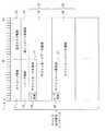
図1は、本発明の第1の実施形態に係る映像データの伝送方法を用いて映像データを伝送する無線通信システムの構成を示すブロック図である。また、図2、図3及び図4は、図1のVICテーブル115t及び127tを示す表である。なお、図1のソース機器110及びシンク機器120の各構成は、以下の第1〜第17の実施形態に適用される。First embodiment.
FIG. 1 is a block diagram illustrating a configuration of a wireless communication system that transmits video data using the video data transmission method according to the first embodiment of the present invention. 2, 3 and 4 are tables showing the VIC tables 115t and 127t in FIG. Each configuration of the source device 110 and the
図1において、本実施形態に係る無線通信システムは、ワイヤレスHDに準拠している。AVコンテンツデータのソース機器として機能するソース機器110は、映像音声再生装置112と、パケット処理回路113と、アンテナ116を備えたパケット無線送受信回路114と、VICテーブル115tをあらかじめ格納するメモリ115と、これらの装置及び回路112〜115の動作を制御するコントローラ111とを備えて構成される。映像音声再生装置112は、例えばDVDプレーヤであって、外部の記憶装置又はMD、DVDなどの記録媒体から映像データ及び音声データを再生してパケット処理回路113に出力する。ここで、映像データは従来の高精細解像度の映像データ(以下、HD映像データという。)、又は3840ピクセル又は4096ピクセルの有効水平画素数と2160ピクセルの有効垂直画素数とを有する4k2k映像データである。パケット処理回路113は入力される映像データ及び音声データを、ワイヤレスHDによって定義されたパケットの形式のデジタル信号に変換してパケット無線送受信回路114に出力する。このとき、パケット処理回路113は、入力される映像データがHD映像データであるときには当該HD映像データを圧縮せずに上記デジタル信号に変換する一方、入力される映像データが4k2k映像データであるときには当該4k2k映像データを所定の第1の圧縮方法で圧縮して上記デジタル信号に変換する。パケット無線送受信回路114は入力されるデジタル信号に従って搬送波信号をデジタル変調し、変調後の無線信号を、アンテナ116を介してシンク機器120のパケット無線送受信回路122に無線送信する。一方、シンク機器120から無線送信される無線信号はアンテナ116を介してパケット無線送受信回路114によって受信され、パケット無線送受信回路114は受信された無線信号をベースバンド信号に復調した後、パケット処理回路113に出力する。パケット処理回路113は、入力されるベースバンド信号から所定のパケット分離処理により所定の制御コマンドのみを取り出した後にコントローラ111に出力する。 In FIG. 1, the wireless communication system according to the present embodiment is compliant with wireless HD. The source device 110 that functions as a source device for AV content data includes a video /
また、図1において、シンク機器120は、アンテナ128を備えたパケット無線送受信回路122と、パケット処理回路123と、映像音声処理回路124と、スピーカ125と、映像データを表示するディスプレイ126と、EDID(Extended Display Identification Data)データ127d及びVICテーブル127tをあらかじめ格納するメモリ127と、これらの回路等122〜124,127の動作を制御するコントローラ121と、バッファ129とを備えて構成される。また、コントローラ121は、無線ネットワークの使用帯域及び信号送出のタイミング制御を管理する帯域管理部121bを備えて構成される。パケット無線送受信回路122は、アンテナ128を介して受信された無線信号をベースバンド信号に復調した後、パケット処理回路123に出力する。パケット処理回路123は、入力されるデジタル信号から所定のパケット分離処理により映像データ、音声データ及び所定の制御コマンドのみを取り出すことにより受信されたパケットをデコードし、映像データ及び音声データを映像音声処理回路124に出力する一方、制御コマンドをコントローラ121に出力する。ここで、パケット処理回路123は、取り出された映像データが圧縮されている場合には、バッファ129を用いて当該映像データを伸張する。映像音声処理回路124は入力される音声データを所定の信号処理やD/A変換処理を実行した後、スピーカ125に出力して音声の出力を行う一方、入力される映像データを所定の信号処理やD/A変換処理を実行した後、ディスプレイ126に出力して表示する。 In FIG. 1, the
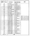
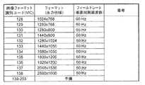
図2〜図4において、VICテーブル115t及び127tはそれぞれ、映像データの映像フォーマットを識別するための映像フォーマット識別子(VIC)を含む。ここで、映像フォーマットは映像データの出力仕様のフォーマットを表し、映像データの有効垂直画素数及び有効水平画素数、走査方法(プログレッシブ(p)又はインターレース(i))、並びに垂直同期周波数(フィールドレートともいう。)の各情報を含む。本実施形態において、48から52の各VICは、4k2k映像データの映像フォーマット(以下、4k2k映像フォーマットという。)に対して、以下のように割り当てられている。 2 to 4, each of the VIC tables 115t and 127t includes a video format identifier (VIC) for identifying the video format of the video data. Here, the video format represents a format of the output specification of the video data, the number of effective vertical pixels and the number of effective horizontal pixels of the video data, the scanning method (progressive (p) or interlace (i)), and the vertical synchronization frequency (field rate). Each information). In the present embodiment, each of the
(a)VICの48は、3840ピクセルの有効水平画素数と、2160ピクセルの有効垂直画素数と、プログレッシブスキャンである走査方法と、23.97Hz又は24Hzのフィールドレートとを有する4k2k映像フォーマットに割り当てられている。
(b)VICの49は、3840ピクセルの有効水平画素数と、2160ピクセルの有効垂直画素数と、プログレッシブスキャンである走査方法と、25Hzのフィールドレートとを有する4k2k映像フォーマットに割り当てられている。
(c)VICの50は、3840ピクセルの有効水平画素数と、2160ピクセルの有効垂直画素数と、プログレッシブスキャンである走査方法と、29.97Hz又は30Hzのフィールドレートとを有する4k2k映像フォーマットに割り当てられている。
(d)VICの51は、4096ピクセルの有効水平画素数と、2160ピクセルの有効垂直画素数と、プログレッシブスキャンである走査方法と、23.97Hz又は24Hzのフィールドレートとを有する4k2k映像フォーマットに割り当てられている。
(e)VICの52は、4096ピクセルの有効水平画素数と、2160ピクセルの有効垂直画素数と、プログレッシブスキャンである走査方法と、25Hzのフィールドレートとを有する4k2k映像フォーマットに割り当てられている。(A)
(B)
(C)
(D)
(E)
なお、図2〜図4のVICのうち、「a」を付加したVICのモードは、出力インターフェースが複製された画素(replicated pixel)を必要とするときに用いられる。これらのVICを送信機(ソース機器110である。)で用いること及び受信機(シンク機器120である。)で映像画素の複製を行うことは、実装者の責任のもとで行われる。 2 to 4, the VIC mode to which “a” is added is used when the output interface requires a replicated pixel. The use of these VICs in the transmitter (which is the source device 110) and the copying of the video pixels in the receiver (which is the sink device 120) are performed under the responsibility of the implementer.
図1において、EDIDデータ127dは、VICテーブル127tに含まれるVICのうちディスプレイ126を用いて表示可能な映像データの各VIC、ディスプレイ126の製品情報及び製造者名、映像符号化方式(例えば、RGB、YCbCr4:4:4又はYCbCr4:2:2)及び音声出力サンプリング等の音声出力仕様(以下、音声フォーマットという。)等のデータを含む。 In FIG. 1,
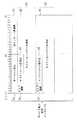
図5は、図1の無線通信システムの動作を示すシーケンス図である。まず始めに、ソース機器110とシンク機器120との間で、シンク機器120がサポートする映像フォーマットの情報及び音声フォーマットの情報をソース機器110が取得するためのデバイス能力取得処理(入力フォーマット取得処理)が実行される。デバイス能力取得処理において、ソース機器110は、シンク機器120のデバイス能力の情報を要求するデバイス能力要求(DEVICE_CAPABILITY_REQUEST)メッセージ(デバイス情報要求メッセージともいう。)1をシンク機器120に無線送信する。これに応答して、シンク機器120は、シンク機器120のデバイス能力の情報を含むデバイス能力応答(DEVICE_CAPABILITY_RESPONSE)メッセージ(デバイス情報応答メッセージともいう。)2をソース機器110に無線送信する。 FIG. 5 is a sequence diagram showing an operation of the wireless communication system of FIG. First, device capability acquisition processing (input format acquisition processing) for the source device 110 to acquire video format information and audio format information supported by the
次に、図5において、ソース機器110とシンク機器120との間で、機器接続処理が行われる。本実施形態では、ソース機器110が機器接続処理、ポート予約処理及び帯域予約処理を起動(イニシエート)する。機器接続処理において、始めに、ソース機器110はワイヤレスHDに準拠した接続要求(CONNECT_REQUEST)メッセージ6をシンク機器120に無線送信することにより、AVデータをシンク機器120に送信するか否かを確認する。このとき、接続要求メッセージ6のSビットは0にセットされ、ポート領域はソースポートを表すデータを格納する。シンク機器120は、接続要求メッセージ6を受信すると、ソース機器110からの接続要求に対する結果の情報を含むワイヤレスHDに準拠した接続応答(CONNECT_RESPONSE)メッセージ7をソース機器110に無線送信する。ここで、シンク機器120は、ソース機器110からの接続要求を受け入れるときは、接続応答メッセージ7の結果コード領域に「成功」を表すデータを格納し、シンクポート領域にAVデータ伝送のために予約されたシンクポートのデータを格納する。接続要求メッセージ6のRFビットに1がセットされている場合には、シンク機器120は、接続応答メッセージ7の所定の領域(総データ長領域、フォーマットタイプ領域、データ長領域及びフォーマットデータ領域)に、サポートされるフォーマットの情報を格納する。接続要求メッセージ6のRFビットに0がセットされている場合には、シンク機器120は、接続応答メッセージ7の総データ長領域に0を格納する。シンク機器120は、ソース機器110からの接続要求を拒否するときは、接続応答メッセージ7の結果コード領域に適切な理由を有する「失敗」を表すデータを格納する。 Next, in FIG. 5, device connection processing is performed between the source device 110 and the
図5において、ソース機器110は、「成功」を示す接続応答メッセージ7を無線受信すると、ソース機器110からシンク機器120に映像データ及び音声データを含むAVコンテンツデータを伝送するための伝送帯域を確保するためのワイヤレスHDに準拠した帯域(リソース)予約処理を行う。帯域予約処理において、ソース機器110は、AVデータを送信するための帯域を要求して予約するために帯域要求コマンドをシンク機器120に無線送信する。これに応答して、シンク機器120の帯域管理部121bは、ソース機器110からシンク機器120にAVコンテンツデータを送信するために必要な予約期間を割り当て、割り当てた予約期間の情報を含む期間指定コマンドをソース機器110に無線送信する。 In FIG. 5, when the source device 110 wirelessly receives the
さらに、図5において、ソース機器110は帯域予約処理を正常に終了すると、ストリーム開始通知メッセージ8をシンク機器120に無線送信する。このとき、ストリーム開始通知メッセージ8の結果コード領域82(図16参照。)には「成功」を表すデータが格納される。なお、ソース機器110は帯域予約処理に失敗すると、「失敗」を表すデータを格納した結果コード領域82を含むストリーム開始通知メッセージ8をシンク機器120に無線送信する。なお、詳細後述するように、ストリーム開始通知メッセージ8は、シンク機器120に送信するAVデータの映像フォーマットの情報及び音声フォーマットの情報を含む。HRP(High Rate Physical layer)ストリームが割り当てられると、ソース機器110は、シンク機器120から当該シンク機器120がデータを有するHRPストリームのHRPパケットを受信する準備ができたことを表すACK(Acknowledgement)信号を受信するまで、PHY(Physical layer)ヘッダ及びMAC(Medium Access Control)ヘッダのみを含むHRPパケットをシンク機器120に無線送信する。ソース機器110は、上記ACK信号を受信すると、HRPパケットにAVデータを挿入してシンク機器120に無線送信する。 Further, in FIG. 5, when the source device 110 normally ends the bandwidth reservation process, the source device 110 wirelessly transmits the stream
また、図5において、ソース機器110は、AVデータの映像フォーマット及び音声フォーマットのうちの少なくとも一方が変更されたときに、当該変更された映像フォーマット及び音声フォーマットのAVデータをシンク機器120に無線送信する前に、変更された映像フォーマット及び音声フォーマットの情報を含む出力フォーマット通知メッセージ(OUTPUT_FORMAT_NOTIFY)メッセージ10を、シンク機器120に無線送信する。 Further, in FIG. 5, when at least one of the video format and audio format of AV data is changed, the source device 110 wirelessly transmits AV data of the changed video format and audio format to the
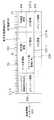
図6は、図5のデバイス能力要求メッセージ1のフォーマットを示す図である。図6において、デバイス能力要求メッセージ1は、以下の各領域を含む。
(1)デバイス能力要求メッセージ1のタイプを表すデータを格納するオペコード領域11。図6において、オペコード領域11は、このデバイス能力要求メッセージ1がデバイス能力要求メッセージであることを表すデータを格納する。
(2)シンク機器120に対して要求するデバイス能力のタイプを表すビットマップデータを格納する要求タイプ領域12。
(3)将来の利用のために予約されたリザーブ領域13。
(4)デバイス能力要求メッセージ1から、オペコード領域11と、要求タイプ領域12と、リザーブ領域13と、総メッセージ長領域14とを除いた領域のデータ長を表すデータを格納する総メッセージ長領域14。
(5)タイプ領域16と、サブメッセージ長領域17と、サブメッセージデータ領域18とをそれぞれ含む少なくとも1つのサブメッセージ15。FIG. 6 is a diagram showing a format of the device
(1) An
(2) A
(3) A reserved
(4) Total
(5) At least one
ただし、サブメッセージ15において、タイプ領域16はサブメッセージデータ領域18に格納されるデータのタイプを表すデータを格納し、サブメッセージ長領域17はサブメッセージデータ領域18に格納されるデータのデータ長を表すデータを格納し、サブメッセージデータ領域18は、タイプ領域16に格納されたタイプのデータを格納する。さらに、デバイス能力要求メッセージ1には、デバイス能力要求メッセージ1の宛先機器のID及び送信元のソース機器110のIDのデータを含むヘッダ(図示せず。)が付加される。 However, in the
図7は、図6の要求タイプ領域12を用いて要求されるデバイス能力のタイプを示す表である。図7に示すように、要求タイプ領域12を用いて要求されるデバイス能力のタイプは、デバイス情報と、デバイス名と、MACアドレスと、入力フォーマット(サポートされるフォーマット(suppurted format))情報と、ベンダー定義とを含む。例えば、ソース機器110は、シンク機器120に対して入力フォーマット情報を要求するときに、要求タイプ領域12に格納されるビットマップデータの入力フォーマット情報に対応するビットに1をセットする。 FIG. 7 is a table showing the types of device capabilities required using the
図8は、図5のデバイス能力応答メッセージ2のフォーマットを示す図である。図8において、デバイス能力応答メッセージ2は以下の各領域を含む。
(1)デバイス能力応答メッセージ2のタイプを表すデータを格納するオペコード領域21。図8において、オペコード領域21は、このデバイス能力応答メッセージ2がデバイス能力応答メッセージであることを表すデータを格納する。
(2)デバイス能力応答メッセージ2から、オペコード領域21と総メッセージ長領域22とを除いた領域のデータ長を表すデータを格納する総メッセージ長領域22。
(3)タイプ領域24と、サブメッセージ長領域25と、サブメッセージデータ領域26とをそれぞれ含む少なくとも1つのサブメッセージ23。FIG. 8 is a diagram showing a format of the device
(1) An
(2) A total
(3) At least one
ただし、サブメッセージ23において、タイプ領域24はサブメッセージデータ領域26に格納されるデータのタイプを表すデータを格納し、サブメッセージ長領域25はサブメッセージデータ領域26に格納されるデータのデータ長を表すデータを格納し、サブメッセージデータ領域26は、タイプ領域24に格納されたタイプのデータを格納する。以下、デバイス情報に対応するデータを格納するタイプ領域24を含むサブメッセージ23をデバイス情報メッセージ3といい、入力フォーマット情報に対応するデータを格納するタイプ領域24を含むサブメッセージ23を入力フォーマット情報メッセージ5という。なお、デバイス能力応答メッセージ2には、デバイス能力応答メッセージ2の宛先機器のID及び送信元のシンク機器120のIDを含むヘッダ(図示せず。)が付加される。 However, in the
図9は、図5のデバイス能力応答メッセージ2と、デバイス情報メッセージ3と、入力フォーマット情報メッセージ5との関係を示す図である。シンク機器120は、受信したデバイス能力要求メッセージ1の要求タイプ領域12に格納されたビットマップデータのデバイス情報に対応するビットが1にセットされているとき、デバイス能力応答メッセージ2の1つのサブメッセージ23のタイプ領域24にデバイス情報に対応するデータを格納し、当該サブメッセージ23をデバイス情報メッセージ3としてソース機器110に無線送信する。また、シンク機器120は、受信したデバイス能力要求メッセージ1の要求タイプ領域12に格納されたビットマップデータの入力フォーマット情報に対応するビットが1にセットされているとき、デバイス能力応答メッセージ2の1つのサブメッセージ23のタイプ領域24に入力フォーマット情報に対応するデータを格納し、当該サブメッセージ23を入力フォーマット情報メッセージ5としてソース機器110に無線送信する。 FIG. 9 is a diagram showing the relationship among the device
図10は、図9のデバイス情報メッセージ3のフォーマットを示す図である。図10において、デバイス情報メッセージ3は、以下の各領域を含む。
(1)デバイス情報に対応するデータを格納するタイプ領域24。
(2)デバイス情報メッセージ3からタイプ領域24とサブメッセージ長領域25とを除いた領域のデータ長を表すデータを格納するサブメッセージ長領域25。
(3)テレビジョン放送受信機、DVDプレーヤ及びセットトップボックスなどのデバイスカテゴリを表すデータを格納するデバイスカテゴリ領域31。
(4)規格のバージョンを表すデータを格納するバージョン領域32。例えば、バージョン1.0又は1.0aの場合は、バージョン領域32は1を格納し、バージョン1.1の場合はバージョン領域32には2を格納する。
(5)A/Vタイプを表すビットマップデータを格納するA/Vタイプ領域33。A/Vタイプを表すビットマップデータのビット0(LSB:Least Significant Bit)は映像ソース機器の機能に割り当てられ、ビット1は映像シンク機器の機能に割り当てられ、ビット2は音声ソース機器の機能に割り当てられ、ビット3は音声シンク機器の機能に割り当てられている。ビットマップデータのビットの値が1にセットされているとき、機器が当該ビットに対応する機能をサポートしていることを示す一方、ビットの値が0にセットされているとき、機器が当該ビットに対応する機能をサポートしていないことを示す。
(6)高速送受信が可能な無線タイプなどの無線タイプを表すデータを格納する無線タイプ領域34。
(7)ソース機器110が高速接続機能(fast connect sequence:ファーストコネクトシーケンス)をサポートしているか否かを表すデータを格納するFC(Fast Connect)領域35。FC領域35は、ソース機器110が高速接続機能をサポートしているときに1を格納する一方、サポートしていないときに0を格納する。
(8)ソース機器110が所定の高速映像フォーマット適応機能(fast video adaptatiion:ファーストビデオアダプテーション)をサポートしているか否かを表すデータを格納するFV(Fast Video)領域36。FV領域36は、ソース機器110が所定の高速映像フォーマット適応機能をサポートしているときに1を格納する一方、サポートしていないときに0を格納する。
(9)ソース機器110が所定の高速音声フォーマット適応機能(fast audio adaptatiion:ファーストオーディオアダプテーション)をサポートしているか否かを表すデータを格納するFA(Fast Audio)領域37。FV領域37は、ソース機器110が所定の高速音声フォーマット適応機能をサポートしているときに1を格納する一方、サポートしていないときに0を格納する。
(10)機器がHDMI(High−Definition Multimedia Interface)において規定されているパススルーモードをサポートしているか否かを表すデータを格納するPT(Pass Through)領域38。PT領域38は、機器がパススルーモードをサポートしているときに1を格納する一方、サポートしていないときに0を格納する。
(11)機器がシンク機器でありかつ所定のコンテンツタイプ通知機能をサポートしているか否かを表すデータを格納するCF(Content Flag)領域39。CF領域39は、機器がコンテンツタイプ通知機能をサポートしているときに1を格納する一方、サポートしていないときに0を格納する。
(12)機器がデバイス制御機能(DEVCTRL)をサポートしているか否かを表すデータを格納するDC(Device Control)領域40。DC領域40は、機器がデバイス制御機能をサポートしているときに1を格納する一方、サポートしていないときに0を格納する。
(13)機器が所定の色分割(クロマパーティショニング)をサポートしているか否かを表すデータを格納するCR(Chroma)領域41。CR領域41は、機器が色分割をサポートしているときに1を格納する一方、サポートしていないときに0を格納する。
(14)将来の利用のために予約されたリザーブ領域43。FIG. 10 is a diagram showing a format of the
(1) A
(2) A sub
(3) A
(4) A
(5) An A /
(6) A
(7) An FC (Fast Connect)
(8) An FV (Fast Video)
(9) A FA (Fast Audio)
(10) A PT (Pass Through)
(11) A CF (Content Flag)
(12) A DC (Device Control)
(13) A CR (Chroma)
(14) A reserved
図11は、図9の入力フォーマット情報メッセージ5のフォーマットを示す図である。図11において、入力フォーマット情報メッセージ5は、以下の各領域を含む。
(1)入力フォーマット情報に対応するデータを格納するタイプ領域24。
(2)入力フォーマット情報メッセージ5からタイプ領域24とサブメッセージ長領域25とを除いた領域のデータ長を表すデータを格納するサブメッセージ長領域25。
(3)将来の利用のために予約されたリザーブ領域53。
(4)フォーマットタイプ領域55と、データ長領域56と、フォーマットデータ領域57とをそれぞれ含む少なくとも1つのフォーマットデータメッセージ54。FIG. 11 is a diagram showing the format of the input
(1) A
(2) A sub
(3) A reserved
(4) At least one
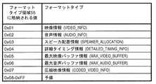
ここで、各フォーマットデータメッセージ54において、フォーマットタイプ領域55はフォーマットデータ領域57に格納されるデータのタイプを表すデータを格納し、データ長領域56はフォーマットデータ領域57に格納されるデータのデータ長を表すデータを格納し、フォーマットデータ領域57はフォーマットタイプ領域55に格納されたフォーマットタイプのデータを格納する。 Here, in each
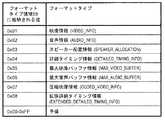
図12は、図11のフォーマットタイプ領域55に格納される値とフォーマットタイプとの関係を示す表である。図12に示すように、フォーマットタイプ領域55に格納される各値に対応するフォーマットタイプは、映像情報(VIDEO_INFO)と、音声情報(AUDIO_INFO)と、スピーカ配置情報(SPEAKER_ALLOCATION)と、詳細タイミング情報(DETAILED_TIMING_INFO)と、最大映像バッファ情報(MAXIMUM_VIDEO_BUFFER)と、最大音声バッファ情報(MAXIMUM_AUDIO_BUFFER)と、圧縮映像情報(CODED_VIDEO_INFO)とを含む。以下、映像情報に対応する値(0x01)を格納するフォーマットタイプ領域55を含むフォーマットデータメッセージ54を映像情報メッセージ200といい、詳細タイミング情報に対応する値(0x04)を格納するフォーマットタイプ領域55を含むフォーマットデータメッセージ54を詳細タイミング情報メッセージ300といい、圧縮映像情報に対応する値(0x07)を格納するフォーマットタイプ領域55を含むフォーマットデータメッセージ54を圧縮映像情報メッセージ400という(図9参照。)。なお、本明細書において、0xから始まる数値は16進数を表し、0bから始まる数値は2進数を表す。 FIG. 12 is a table showing the relationship between values stored in the
図13は、図9の映像情報メッセージ200のフォーマットを示す図である。図13において、映像情報メッセージ200は、以下の各領域を含む。
(1)映像情報に対応する値(0x01)を格納するフォーマットタイプ領域55。
(2)映像情報メッセージ200からフォーマットタイプ領域55とデータ長領域56とを除いた領域のデータ長を表すデータを格納するデータ長領域56。
(3)サポートされる色空間を表すビットマップデータを格納する色空間領域201。色空間領域201に格納されるビットマップデータのビット0はRGBに割り当てられ、ビット1はYCbCr422に割り当てられ、ビット2はYCbCr444に割り当てられ、ビット3は予備ビットである。ビットマップデータのビットの値が1にセットされているとき、当該ビットに対応する色空間がサポートされていることを示す一方、ビットの値が0にセットされているとき、当該ビットに対応する色空間がサポートされていないことを示す。
(4)機器がフルレンジ及びリミテッドレンジのRGB量子化のうちのいずれをサポートするか、及び機器がフルレンジ及びリミテッドレンジのYCrCb量子化のうちのいずれをサポートするかを表すビットマップデータを格納する量子化範囲(QC)領域202。量子化範囲の値はIEC61966−2−1によって定義されている。量子化範囲領域202に格納されたビットマップデータのビット0が1であるときは、機器がフルレンジのRGB量子化をサポートしていることを示す一方、0であるときは、機器がリミテッドレンジのRGB量子化をサポートしていることを示す。また、量子化範囲領域202に格納されたビットマップデータのビット1が1であるときは、機器がフルレンジのYCrCb量子化をサポートしていることを示す一方、0であるときは、機器がリミテッドレンジのYCrCb量子化をサポートしていることを示す。量子化範囲領域202に格納されたビットマップデータのビット2及び3は予備ビットである。ソース機器110は、フルレンジのデータをサポートしていないシンク機器に対してフルレンジのデータを送信しない。アドビ(Adobe)601及びsYCC601は、常にフルレンジである。
(5)サポートされるアスペクト比を表すビットマップデータを格納するAR(Aspect Ratio)領域203。AR領域203に格納されるビットマップデータのビット0は4:3のアスペクト比に割り当てられ、ビット1は16:9のアスペクト比に割り当てられている。ビットマップデータのビットの値が1にセットされているとき、当該ビットに対応するアスペクト比がサポートされていることを示す一方、ビットの値が0にセットされているとき、当該ビットに対応するアスペクト比がサポートされていないことを示す。
(6)サポートされる色深度を表すビットマップデータを格納する色深度領域204。色深度領域204に格納されるビットマップデータのビット0は24ビットの色深度に割り当てられ、ビット1は30ビットの色深度に割り当てられ、ビット2は36ビットの色深度に割り当てられ、ビット3は48ビットの色深度に割り当てられ、ビット4及び5は予備ビットである。ビットマップデータのビットの値が1にセットされているとき、当該ビットに対応する色深度がサポートされていることを示す一方、ビットの値が0にセットされているとき、当該ビットに対応する色深度がサポートされていないことを示す。
(7)サポートされるカラリメトリ(Colorimetry)を表すデータを格納するカラリメトリ領域205。カラリメトリ領域205に格納されるビットマップデータのビット0はITU601/SMPTE170Mに割り当てられ、ビット1はITU709に割り当てられ、ビット2は標準の解像度の原色を用いるIEC61966−2−4をサポートするためにxvYCC601に割り当てられ、ビット3は高精細の原色を用いるIEC61966−2−4をサポートするためにxvYCC709に割り当てられ、ビット4は静止画像の原色を用いるIEC61966−2−1−am1をサポートするためにsYCC601に割り当てられ、ビット5は静止画像の原色を用いるIEC61966−2−5(CVD)をサポートするためにアドビYCC601に割り当てられ、ビット6はアドビRGBに割り当てられ、ビット7は予備ビットである。ただし、シンク機器がRGB色空間をサポートしていないときは、カラリメトリ領域205に格納されるビットマップデータのビット6は0にセットされ、シンク機器がYCbCr色空間をサポートしていないときは、ビット2は0にセットされる。
(8)シンク機器120がサポートする映像フォーマットの総数N(Nは1以上の整数である。)を格納するフォーマット数領域206。
(9)シンク機器120がサポートする映像フォーマットのVICをそれぞれ格納するN個のVIC領域207−1〜207−N。
(10)映像情報メッセージ200のメッセージ長を所定のデータ長の単位(本実施形態において、32ビットである。)の整数倍に揃えるために設けられるパディング領域208。FIG. 13 is a diagram showing a format of the
(1) A
(2) A
(3) A
(4) Quantities that store bitmap data indicating whether the device supports full range or limited range RGB quantization and whether the device supports full range or limited range YCrCb quantization Range (QC) region 202. The value of the quantization range is defined by IEC 61966-2-1. When
(5) An AR (Aspect Ratio) area 203 for storing bitmap data representing a supported aspect ratio.
(6) A
(7) A
(8) A
(9) N VIC areas 207-1 to 207-N each storing VICs of video formats supported by the
(10) A
図14は、図9の詳細タイミング情報メッセージ300のフォーマットを示す図である。図14において、詳細タイミング情報メッセージ300は、以下の各領域を含む。
(1)詳細タイミング情報に対応する値(0x04)を格納するフォーマットタイプ領域55。
(2)詳細タイミング情報メッセージ300からフォーマットタイプ領域55とデータ長領域56とを除いた領域のデータ長を表すデータを格納するデータ長領域56。
(3)詳細タイミング情報(Detailed Timing Info)のID番号を格納するID領域302。
(4)ピクセルクロック周波数を格納するピクセルクロック領域304。
(5)水平有効期間Hactiveの有効画素数を格納する水平有効期間領域305。
(6)水平ブランキング期間(ブランク期間)Hblankの画素数を格納する水平ブランキング期間領域307。
(7)垂直有効期間Vactiveの有効画素数を格納する垂直有効期間領域309。
(8)垂直ブランキング期間Vblankの画素数を格納する垂直ブランキング期間領域311。
(9)水平同期パルスHsyncの水平ブランキング期間Hblankの先頭からのオフセット期間である水平同期パルス前駆期間(水平同期オフセット期間)Hfrontの長さを画素数で表した値を格納する水平同期オフセット領域313。
(10)垂直同期パルスVsyncの垂直ブランキング期間Vblankの先頭からのオフセット期間である垂直同期パルス前駆期間(垂直同期オフセット期間)Vfrontの長さを画素数で表した値を格納する垂直同期オフセット領域314。
(11)水平同期パルスHsyncのパルス幅を画素数で表した値を格納する水平同期パルス幅領域315。
(12)垂直同期パルスVsyncのパルス幅を画素数で表した値を格納する垂直同期パルス幅領域316。
(13)画像の水平方向のサイズをミリメートル単位で表した値を格納する水平画像サイズ領域317。
(14)画像の垂直方向のサイズをミリメートル単位で表した値を格納する垂直画像サイズ領域319。
(15)水平方向の境界を表すデータを格納する水平境界領域321。
(16)垂直方向の境界を表すデータを格納する垂直境界領域322。
(17)ステレオ映像に関わる情報を格納するフラグ領域323。
(18)将来の利用のために予約されたリザーブ領域301,303,306,308,310,312,318,320及び324。FIG. 14 is a diagram showing a format of the detailed
(1) A
(2) A
(3) An
(4) A pixel clock area 304 for storing the pixel clock frequency.
(5) A horizontal effective period area 305 for storing the number of effective pixels in the horizontal effective period Hactive.
(6) Horizontal blanking period (blank period) A horizontal blanking period area 307 for storing the number of pixels of Hblank.
(7) A vertical effective period area 309 for storing the number of effective pixels in the vertical effective period Vactive.
(8) A vertical blanking period region 311 for storing the number of pixels in the vertical blanking period Vblank.
(9) Horizontal sync offset area for storing a value representing the length of the horizontal sync pulse precursor period (horizontal sync offset period) Hfront, which is an offset period from the head of the horizontal blanking period Hblank of the horizontal sync pulse Hsync, in terms of the number of pixels. 313.
(10) Vertical synchronization offset region for storing a value representing the length of the vertical synchronization pulse precursor period (vertical synchronization offset period) Vfront, which is an offset period from the head of the vertical blanking period Vblank of the vertical synchronization pulse Vsync, in terms of the number of pixels 314.
(11) A horizontal synchronization
(12) A vertical synchronization pulse width region 316 for storing a value representing the pulse width of the vertical synchronization pulse Vsync in terms of the number of pixels.
(13) A horizontal image size area 317 for storing a value representing the horizontal size of the image in millimeters.
(14) A vertical image size area 319 for storing a value representing the vertical size of the image in millimeters.
(15) A horizontal boundary region 321 for storing data representing a horizontal boundary.
(16) A vertical boundary region 322 for storing data representing a boundary in the vertical direction.
(17) A flag area 323 for storing information related to stereo video.
(18) Reserved areas 301, 303, 306, 308, 310, 312, 318, 320, and 324 reserved for future use.
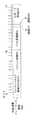
図15は、水平有効期間Hactive、水平ブランキング期間Hblank、水平周波数Hfreq、垂直有効期間Vactive、垂直ブランキング期間Vblank及び垂直周波数Vfreqの各定義を示すタイミングチャートであり、図16は、水平同期パルス前駆期間Hfront、水平同期パルスHsync、水平同期パルス後駆期間Hback、垂直同期パルス前駆期間Vfront、垂直同期パルスVsync、及び垂直同期パルス後駆期間Vbackの各定義を示すタイミングチャートである。図16において、データイネーブル信号(Data Enable)は有効画素の開始及び終了タイミングを示し、水平同期信号HSは水平同期パルスHsyncを伝送し、垂直同期信号VSは垂直同期パルスVsyncを伝送する。また、水平同期パルス前駆期間Hfrontは水平ブランキング期間Hblankの中の水平同期信号HSがハイレベルになる前の期間であり、水平同期パルスHsyncは水平同期信号HSがハイレベルを有する期間であり、水平同期パルス後駆期間Hbackは水平ブランキング期間Hblankの中の水平同期パルスHsyncの後の水平同期信号HSがローレベルを有する期間である。さらに、垂直同期パルス前駆期間Vfrontは垂直ブランキング期間Vblankの中で垂直同期信号VSがハイレベルになる前の期間であり、水力同期パルスVsync垂直同期信号VSがハイレベルを有する期間であり、垂直同期パルス後駆期間Vbackは垂直ブランキング期間Vblankの中の垂直同期パルスVsyncの後の垂直同期信号VSがローレベルを有する期間である。 FIG. 15 is a timing chart showing definitions of a horizontal effective period Hactive, a horizontal blanking period Hblank, a horizontal frequency Hfreq, a vertical effective period Vactive, a vertical blanking period Vblank, and a vertical frequency Vfreq. FIG. 10 is a timing chart showing definitions of a precursor period Hfront, a horizontal sync pulse Hsync, a horizontal sync pulse follow-up period Hback, a vertical sync pulse precursor period Vfront, a vertical sync pulse Vsync, and a vertical sync pulse follow-up period Vback. In FIG. 16, a data enable signal (Data Enable) indicates the start and end timing of an effective pixel, the horizontal synchronization signal HS transmits a horizontal synchronization pulse Hsync, and the vertical synchronization signal VS transmits a vertical synchronization pulse Vsync. The horizontal synchronization pulse precursor period Hfront is a period before the horizontal synchronization signal HS in the horizontal blanking period Hblank becomes high level, and the horizontal synchronization pulse Hsync is a period in which the horizontal synchronization signal HS has high level. The horizontal synchronization pulse follow-up period Hback is a period in which the horizontal synchronization signal HS after the horizontal synchronization pulse Hsync in the horizontal blanking period Hblank has a low level. Further, the vertical synchronization pulse precursor period Vfront is a period before the vertical synchronization signal VS becomes high level in the vertical blanking period Vblank, and is a period in which the hydraulic synchronization pulse Vsync vertical synchronization signal VS has high level. The synchronization pulse follow-up period Vback is a period in which the vertical synchronization signal VS after the vertical synchronization pulse Vsync in the vertical blanking period Vblank has a low level.
図17は、図9の圧縮映像情報メッセージ400のフォーマットを示す図である。図17において、圧縮映像情報メッセージ400は、以下の各領域を含む。
(1)圧縮映像情報に対応する値(0x07)を格納するフォーマットタイプ領域55。
(2)圧縮映像情報メッセージ400からフォーマットタイプ領域55とデータ長領域56とを除いた領域のデータ長を表すデータを格納するデータ長領域56。
(3)将来の利用のために予約されたリザーブ領域401。
(4)シンク機器120において処理可能な最小のサブスライスサイズを表すデータをオクテット単位で格納する最小サブスライスサイズ(Minimum Sub−Slice Size)領域402。
(5)シンク機器120がバッファリング可能なスライス数の最大値を表すデータを格納する最大未処理スライス数(Maximum Slices Outstanding)領域403。
(6)圧縮された映像データのために割り当てられたシンク機器120のバッファ129の最大サイズを表すデータをオクテット単位で格納する最大総圧縮映像バッファサイズ(Maximum Total Coded Video Buffer Size)領域404。
(7)シンク機器120が圧縮された映像データのためにバッファリング可能な最大の時間長を表すデータを格納する最大総圧縮映像バッファ時間(Maximum Total Coded Video Buffer Time)領域405。FIG. 17 is a diagram showing a format of the compressed
(1) A
(2) A
(3) A reserved area 401 reserved for future use.
(4) The minimum sub-slice size (Minimum Sub-Slice Size) area 402 that stores data representing the minimum sub-slice size that can be processed by the
(5) The maximum number of unprocessed slices (Maximum Slicings Outstanding) area 403 that stores data representing the maximum number of slices that can be buffered by the
(6) Maximum Total Coded Video Buffer area 404 for storing data representing the maximum size of the
(7) Maximum Total Coded Video Buffer Time area 405 for storing data representing the maximum time length that can be buffered by the
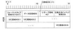
図17において、領域402〜405にそれぞれ格納される各パラメータは、ソース機器110において映像データを所定の第1の圧縮方法で圧縮するときに用いられる圧縮用パラメータである。なお、シンク機器120は、圧縮映像データを伸張できるときには圧縮映像情報メッセージ400をソース機器110に送信する一方、圧縮映像データを伸張できないときには圧縮映像情報メッセージ400をソース機器110に送信しない。 In FIG. 17, each parameter stored in each of regions 402 to 405 is a compression parameter used when the video data is compressed by the predetermined first compression method in the source device 110. The
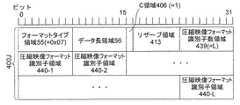
図18は、図5のストリーム開始通知メッセージ8のフォーマットを示す図である。ストリーム開始通知メッセージ8は、ソース機器110からシンク機器120に対して図5の帯域予約処理の結果及びAVデータの出力フォーマット(すなわち、AVデータに含まれる映像データの映像フォーマット及び音声データの音声フォーマットである。)を通知するために用いられる。図18において、ストリーム開始通知メッセージ8は、以下の各領域を含む。
(1)ストリーム開始通知メッセージ8のオペレーションコードを格納するオペコード領域81。
(2)図5の帯域予約処理が成功したか否か(ストリームの送信が正常に開始されるか否か)を表すデータを格納する結果コード領域82。
(3)図5の帯域予約処理においてMAC層から得られた(又は、割り当てられた)ストリームインデックスを格納するストリームインデックス領域83。
(4)AVデータの伝送のために予約されたシンクポート番号を格納するシンクポート領域84。
(5)シンクポート及びソースポートが映像データのために用いられるときには1を格納し、シンクポート及びソースポートが映像データのために用いられないときには0を格納するVP領域85。
(6)シンクポート及びソースポートが音声データのために用いられるときには1を格納し、シンクポート及びソースポートが音声データのために用いられないときには0を格納するAP領域86。
(7)AVデータの伝送のために予約されたソースポート番号を格納するソースポート領域87。
(8)将来の利用ために予約されたリザーブ領域88。
(9)ストリーム開始通知メッセージ8からオペコード領域81と総データ長領域89とを除いた領域のデータ長を表すデータを格納する総データ長領域89。
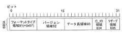
(10)フォーマットタイプ領域91と、バージョン領域92と、データ長領域93と、フォーマットデータ領域94とをそれぞれ含む少なくとも1つのフォーマット領域90。FIG. 18 is a diagram showing the format of the stream
(1) An operation code area 81 for storing the operation code of the stream
(2) A result code area 82 for storing data indicating whether or not the bandwidth reservation process of FIG. 5 is successful (whether or not transmission of the stream is normally started).
(3) A stream index area 83 for storing a stream index obtained (or allocated) from the MAC layer in the bandwidth reservation process of FIG.
(4) A sync port area 84 for storing a sync port number reserved for AV data transmission.
(5) A VP area 85 that stores 1 when the sink port and the source port are used for video data, and
(6) AP area 86 that stores 1 when the sink port and the source port are used for audio data, and
(7) A source port area 87 for storing a source port number reserved for AV data transmission.
(8) A reserved
(9) A total data length area 89 for storing data representing the data length of the area excluding the operation code area 81 and the total data length area 89 from the stream
(10) At least one
ここで、各フォーマット領域90において、フォーマットタイプ領域91はフォーマットデータ領域94に格納されるデータのタイプを表すデータを格納し、バージョン領域92はフォーマットデータ領域94の規格のバージョン番号を格納し、データ長領域93はフォーマットデータ領域94に格納されるデータのデータ長を表すデータを格納し、フォーマットデータ領域94はフォーマットタイプ領域91に格納されたフォーマットタイプのデータを格納する。 Here, in each
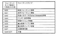
図19は、図18のフォーマットタイプ領域91に格納される値とフォーマットタイプとの関係を示す表である。図19に示すように、フォーマットタイプ領域91に格納される各値に対応するフォーマットタイプは、映像フォーマット情報と、音声フォーマット情報と、色域メタデータ(Gamut Metadata)情報と、ベンダー依存情報と、詳細タイミング情報と、最大映像バッファ情報と、最大音声バッファ情報と、圧縮映像情報とを含む。以下、映像フォーマット情報に対応する値(0x01)を格納するフォーマットタイプ領域91を含むフォーマット領域90を映像フォーマット領域500といい、圧縮映像情報に対応する値(0x07)を格納するフォーマットタイプ領域91を含むフォーマット領域90を圧縮映像フォーマット領域600という。 FIG. 19 is a table showing the relationship between values stored in the format type area 91 of FIG. 18 and format types. As shown in FIG. 19, the format type corresponding to each value stored in the format type area 91 includes video format information, audio format information, gamut metadata information, vendor-dependent information, Detailed timing information, maximum video buffer information, maximum audio buffer information, and compressed video information are included. Hereinafter, a
図20は、図18のストリーム開始通知メッセージ8にフォーマット領域90として含まれる映像フォーマット領域500のフォーマットを示す図である。図20において、映像フォーマット領域500は、以下の各領域を含む。
(1)映像フォーマット情報に対応する値(0x00)を格納するフォーマットタイプ領域91。
(2)以下の領域501〜512の規格のバージョン番号を格納するバージョン領域92。
(3)映像フォーマット領域500からフォーマットタイプ領域91と、バージョン領域92と、データ長領域93とを除いた領域のデータ長を表すデータを格納するデータ長領域93。
(4)送信される映像データの映像フォーマットを表すVICを格納するVIC領域501。
(5)送信される映像データのカラーフォーマットのタイプを表すデータを格納するCS(Color Space:色空間)領域502。CS領域502は、カラーフォーマットのタイプがRGBであるときは0を格納し、YCbCr422であるときは1を格納し、YCbCr444であるときは2を格納する。3から7までの間の値は、予備の値である。
(6)送信される映像データの色深度のビット数を格納するCD(Color Depth:色深度)領域503。CD領域503は、色深度が24ビットであるときは0を格納し、30ビットであるときは1を格納し、36ビットであるときは2を格納し、48ビットであるときは3を格納する。4から7までの間の値は、予備の値である。
(7)送信される映像のアスペクト比を表すデータを格納するPAR(Picture Aspect Ratio:映像アスペクト比)領域504。PAR領域504は、映像アスペクト比が4:3であるときは9を格納し、16:9であるときは10を格納し、14:9であるときは11を格納する。1から8までの間の値及び12から15までの間の値は、予備の値である。FIG. 20 is a diagram showing the format of the
(1) A format type area 91 for storing a value (0x00) corresponding to video format information.
(2) A version area 92 for storing the version numbers of the standards of the following areas 501 to 512.
(3) A data length area 93 that stores data representing the data length of an area excluding the format type area 91, the version area 92, and the data length area 93 from the
(4) A VIC area 501 for storing a VIC representing a video format of video data to be transmitted.
(5) A CS (Color Space) area 502 for storing data representing the type of color format of video data to be transmitted. The CS area 502
(6) A CD (Color Depth) area 503 for storing the number of bits of color depth of transmitted video data. The CD area 503
(7) A PAR (Picture Aspect Ratio) area 504 for storing data representing the aspect ratio of the transmitted video. The PAR area 504
(8)送信される映像データのカラリメトリ情報(ITUBT.601及びBT.709など。)を格納するCM(Colorimetry:カラリメトリ)領域205。CM領域205は、カラリメトリのデータがないときは0を格納し、カラリメトリがITU601/SMPTE170Mであるときは1を格納し、ITU709であるときは2を格納し、xvYCC601であるときは3を格納し、xvYCC709であるときは4を格納し、sYCC601であるときは8を格納し、アドビYCC601であるときは9を格納し、アドビRGBであるときは10を格納する。5から7までの間の値及び11から15までの間の値は、予備の値である。
ソース機器110は、典型的には、送信される映像フォーマットに関する所定のデフォルトのカラリメトリを用いる。CM領域205にカラリメトリを表す値が格納されていない場合、送信される信号のカラリメトリは送信される映像フォーマットに関するデフォルトのカラリメトリと一致する。
図2〜図4のVICテーブル115t,127t内の、480ライン、576ライン、240ライン及び288ラインの映像フォーマットのデフォルトのカラリメトリはSMPTE170Mに基づく。図2〜図4のVICテーブル115t,127t内の720ライン及び1080ラインの高精細の映像フォーマットのデフォルトのカラリメトリはITU709に基づく。その他の映像フォーマットのデフォルトのカラリメトリはsRGBに基づく。
シンク機器120がxvYCC601、xvYCC709又はsYCC601をサポートしていないときは、ソース機器110はできるだけxvYCCで符号化された映像データ又はsYCC601の映像データを送信せず、CM領域205にxvYCC601、xvYCC709及びsYCC601を表す値を格納しない。
CS領域502にYCbCr444又はYCbCr422を表すデータが格納されるときは、ソース機器110はCM領域205にアドビRGBを表す値を格納しない。
後述するCF(Content Flag)領域507において定義される写真モードのデフォルトのカラリメトリはsYCC601に基づいており、sYCC601、アドビYCC601及びアドビRGBのうちから選択される1つのカラリメトリである。アドビRGBはRGB色空間の構成要素であるが、CS領域502に格納された値が0であるときは、アドビRGBを表す値が選択される。
シンク機器120がアドビYCC601又はアドビRGBをサポートしていないときには、ソース機器110はアドビのカラリメトリで符号化された写真ソースデータを送信せず、CM領域205にアドビYCC601及びアドビRGBを表す値を格納しない。(8) A CM (Colorimetry)
The source device 110 typically uses a predetermined default colorimetry regarding the video format to be transmitted. When a value representing colorimetry is not stored in the
The default colorimetry of the video formats of 480 lines, 576 lines, 240 lines and 288 lines in the VIC tables 115t and 127t of FIGS. 2 to 4 is based on SMPTE 170M. The default colorimetry of the high-definition video format of 720 lines and 1080 lines in the VIC tables 115t and 127t of FIGS. 2 to 4 is based on ITU709. The default colorimetry for other video formats is based on sRGB.
When the
When data representing YCbCr444 or YCbCr422 is stored in the CS area 502, the source device 110 does not store a value representing Adobe RGB in the
The default colorimetry of the photo mode defined in a CF (Content Flag) area 507, which will be described later, is based on sYCC601, and is one colorimetry selected from sYCC601, Adobe YCC601, and Adobe RGB. Adobe RGB is a component of the RGB color space, but when the value stored in the CS area 502 is 0, a value representing Adobe RGB is selected.
When the
(9)送信される映像データの有効画素のアスペクト比を表すデータを格納するAFAR(Active Format Aspect Ratio)領域506。AFAR領域506は、映像データの有効画素のアスペクト比が4:3であるときは0を格納し、16:9であるときは10を格納し、14:9であるときは11を格納する。0から8までの間の値及び12から15までの間の値は、予備の値である。(9) An AFAR (Active Format Aspect Ratio) area 506 for storing data representing the aspect ratio of effective pixels of transmitted video data. The AFAR area 506
(10)サポートされるコンテンツの分類(タイプ)を表すデータを格納するCF(Content Flag)領域507。CF領域507は、映像データのコンテンツがデフォルトであるときは0を格納し、テキスト(Text)であるときは8を格納し、写真(Photo)であるときは9を格納し、映画(Cinema)であるときは10を格納し、ゲーム(Game)であるときは11を格納する。1から7までの間の値及び12から15までの間の値は予備の値である。
CF領域507に格納される値は、コンテンツに基づいており、機器のタイプには基づいていない。例えば、動画を再生できるディジタルスチルカメラ、録画されたテレビジョン放送の番組を再生できるDVDプレーヤ及び映画を再生できるゲーム機が存在する。しかしながら、CF領域507に格納されるコンテンツのタイプは以下のように定義される。
テキスト:ビットマップテキストを示す。シンク機器120は、フィルタされていないアナログの再構築(analog reconstruction)なしの結果を表示する。
写真:静止画像を示す。CF領域507が写真を表す値を格納しているとき、CM領域505はsYCC601、アドビ601又はアドビRGBを表す値を格納し、後述するQR(Quantization Range)領域508はフルレンジを表す値を格納する。ソース機器110は、シンク機器120によってサポートされていないカラリメトリを有するコンテンツのデータをシンク機器120に送信しない。シンク機器120は、シンク機器120の画像強調(picture enhancement)の度合いを減少させる。このとき、スケーリングはディスプレイの解像度以下である。
映画:映画ソースデータを示す。シンク機器120は、シンク機器120の画像強調の度合いを減少させる。音声はAVアンプ又はテレビジョン放送受信機のスピーカにリンクされる。
ゲーム:ゲームソースデータを示す。シンク機器120は、シンク機器120の画像強調の度合いを減少させる。音声のレイテンシは最小化される。(10) A CF (Content Flag) area 507 for storing data indicating the classification (type) of supported content. The CF area 507
The value stored in the CF area 507 is based on the content, not based on the device type. For example, there are digital still cameras capable of reproducing moving images, DVD players capable of reproducing recorded television broadcast programs, and game machines capable of reproducing movies. However, the type of content stored in the CF area 507 is defined as follows.
Text: Indicates bitmap text. The
Photo: Shows a still image. When the CF area 507 stores a value representing a photograph, the CM area 505 stores a value representing sYCC 601, Adobe 601, or Adobe RGB, and a QR (Quantization Range) area 508 described later stores a value representing a full range. . The source device 110 does not transmit content data having colorimetry that is not supported by the
Movie: Indicates movie source data. The
Game: Indicates game source data. The
(11)送信される映像データの量子化(ビット)範囲を表すデータを格納するQR(Quantization Range:量子化範囲)領域508。QR領域508は、量子化範囲が映像フォーマットに応じて決められたデフォルトの量子化範囲であるときは0を格納し、リミテッドレンジであるときは1を格納し、フルレンジであるときは2を格納する。
3は予備の値である。
ソース機器110は、シンク機器120によってサポートされていない量子化範囲の映像データをシンク機器120に送信しない。幾つかの映像フォーマットにおいて、使用可能なQR領域508に格納可能な量子化範囲は以下のように制限されている。
RGB映像フォーマット:「リミテッドレンジ」又は「フルレンジ」。
YCbCr映像フォーマット:「リミテッドレンジ」。
VGA(640×480)、sYCC601及びアドビ601映像フォーマット:「フルレンジ」。(11) A QR (Quantization Range) region 508 that stores data representing a quantization (bit) range of video data to be transmitted. The QR area 508
3 is a reserve value.
The source device 110 does not transmit video data in the quantization range that is not supported by the
RGB video format: “Limited range” or “Full range”.
YCbCr video format: “Limited range”.
VGA (640 × 480), sYCC 601 and Adobe 601 video format: “full range”.
(12)送信される映像データのタイミング情報として詳細タイミング情報(DETAILED_TIMING_INFO)が用いられるときは1を格納する一方、用いられないときは0を格納するD(Detailed Timing Information)領域509。
(13)D領域509に1が格納されているときには詳細タイミング情報のIDを格納する一方、0が格納されているときには0を格納するID(ID of Detailed Timing Information領域510。
(14)映像フォーマットのパーティションモードを表すデータを格納するPM(Partition Mode)領域511。PM領域511は、パーティションモードが2x2であるときは0b000を格納し、1x1であるときは0b001を格納し1x2であるときは0b010を格納し、2x1であるときは0b011を格納し、2x4であるときは0b100を格納し、4x2であるときは0b101を格納し、4x4であるときは0b110を格納し、2x2クロマであるときは0b111を格納する。
(15)将来の利用ために予約されたリザーブ領域512。(12) A D (Detailed Timing Information) area 509 that stores 1 when detailed timing information (DETAILED_TIMING_INFO) is used as timing information of video data to be transmitted, and
(13) The ID of the detailed timing information is stored when 1 is stored in the D area 509, while the ID (ID of Detailed Timing Information area 510
(14) A PM (Partition Mode) area 511 for storing data representing the partition mode of the video format. The PM area 511 stores 0b000 when the partition mode is 2x2, stores 0b001 when it is 1x1, stores 0b010 when it is 1x2, stores 0b011 when it is 2x1, and is 2x4. 0b100 is stored, 0b101 is stored when it is 4x2, 0b110 is stored when it is 4x4, and 0b111 is stored when it is 2x2 chroma.
(15) A reserved area 512 reserved for future use.
図21は、図18のストリーム開始通知メッセージ8にフォーマット領域90として含まれる圧縮映像フォーマット領域600のフォーマットを示す図である。図21において、圧縮映像フォーマット領域600は、以下の各領域を含む。
(1)圧縮映像フォーマット情報に対応する値(0x07)を格納するフォーマットタイプ領域91。
(2)バージョン番号0x01を格納するバージョン領域92。
(3)以下の領域601〜603の総データ長を表すデータを格納するデータ長領域93。
(4)送信される映像データが圧縮されているときに1を格納する一方、送信される映像データが圧縮されていないときに0を格納するA(Active)領域601。
(5)パーティショニングモードが用いられるときに1を格納し、用いられない時に0を格納するP(Partition Mode)領域602。
(6)将来の利用ために予約されたリザーブ領域603。FIG. 21 is a diagram showing the format of the compressed video format area 600 included as the
(1) A format type area 91 for storing a value (0x07) corresponding to the compressed video format information.
(2) A version area 92 for storing the version number 0x01.
(3) A data length area 93 for storing data representing the total data length of the following areas 601 to 603.
(4) An A (Active) area 601 that stores 1 when the transmitted video data is compressed, and
(5) A P (Partition Mode) area 602 that stores 1 when the partitioning mode is used and
(6) A reserved area 603 reserved for future use.
図22は、図5の出力フォーマット通知メッセージ10のフォーマットを示す図である。ソース機器110は、AVデータをシンク機器120に送信する前に、及び、AVデータの映像フォーマット及び音声フォーマットのうちの少なくとも一方が変化されたときに、送信するAVデータの映像フォーマット及び音声フォーマットを含む出力フォーマット通知メッセージ10を、シンク機器120に送信する。図22において、出力フォーマット通知メッセージ10は、以下の各領域を含む。
(1)出力フォーマット通知メッセージ10のオペレーションコードを格納するオペコード領域101。
(2)AVデータの伝送のために予約されたシンクポート番号を格納するシンクポート領域102。
(3)シンクポート及びソースポートが映像データのために用いられるときには1を格納し、シンクポート及びソースポートが映像データのために用いられないときには0を格納するVP領域103。
(4)シンクポート及びソースポートが音声データのために用いられるときには1を格納し、シンクポート及びソースポートが音声データのために用いられないときには0を格納するAP領域104。
(5)AVデータの伝送のために予約されたソースポート番号を格納するソースポート領域105。
(6)出力フォーマット通知メッセージ10からオペコード領域101と総データ長領域107を除いた領域のデータ長を表すデータを格納する総データ長領域107。
(7)将来の利用ために予約されたリザーブ領域106及び108。
(8)フォーマットタイプ領域91と、バージョン領域92と、データ長領域93と、フォーマットデータ領域94とをそれぞれ含む少なくとも1つのフォーマット領域90。なお、図22において、フォーマット領域90は、図8のストリーム開始通知メッセージ8のフォーマット領域90と同様に構成される。FIG. 22 is a diagram showing the format of the output
(1) An operation code area 101 for storing an operation code of the output
(2) A sync port area 102 for storing a sync port number reserved for AV data transmission.
(3) A VP area 103 that stores 1 when the sink port and the source port are used for video data, and
(4) AP area 104 that stores 1 when the sink port and the source port are used for audio data, and
(5) A source port area 105 for storing a source port number reserved for AV data transmission.
(6) A total data length area 107 for storing data representing the data length of the area excluding the operation code area 101 and the total data length area 107 from the output
(7) Reserved areas 106 and 108 reserved for future use.
(8) At least one
次に、図5を参照して、ソース機器110がシンク機器120に圧縮映像データを含むAVデータを送信するときの図1の無線通信システムの動作を説明する。まず、ソース機器110は、デバイス能力要求メッセージ1の1つのサブメッセージ15のタイプ領域16に「入力フォーマット情報」を表すデータを格納して(図6及び図7参照。)シンク機器120に送信することにより、シンク機器120に対してシンク機器120がサポートする入力フォーマットの情報を要求する。これに応答して、シンク機器120は、映像情報メッセージ200と圧縮映像情報メッセージ400とを含む入力フォーマット情報メッセージ5を含むデバイス能力応答メッセージ2(図9参照。)をソース機器110に送信する。ここで、映像情報メッセージ200は、EDIDデータ127dに含まれるシンク機器120がサポートする映像フォーマットのVICを含む。また、圧縮映像情報メッセージ400は、ソース機器110において映像データを所定の第1の圧縮方法で圧縮するときに用いられる圧縮用パラメータを含む。ここで、圧縮用パラメータは、シンク機器120において処理可能な最小のサブスライスサイズと、シンク機器120がバッファリング可能なスライス数の最大値と、圧縮された映像データのために割り当てられたシンク機器120のバッファ129の最大サイズを表すデータと、シンク機器120が圧縮された映像データのためにバッファリング可能な最大の時間長とを含む。 Next, the operation of the wireless communication system of FIG. 1 when the source device 110 transmits AV data including compressed video data to the
さらに、図5において、ソース機器110はデバイス能力応答メッセージ2を受信すると、受信されたデバイス能力応答メッセージ2の映像情報メッセージ200に含まれるVICの中から1つのVICを選択し、VICテーブル115tを参照して、選択されたVICの映像フォーマットを識別する。また、ソース機器110は、デバイス能力応答メッセージ2が圧縮映像情報メッセージ400を含むか否かに基づいて、シンク機器120において圧縮映像データを伸張できるか否かを判断する。そして、パケット処理回路113は、映像音声再生装置112からの映像データに基づいて、識別された映像フォーマットの映像データを生成する。さらに、パケット処理回路113は、生成された映像データを、受信された圧縮映像情報メッセージ400に含まれる圧縮用パラメータを用いて所定の第1の圧縮方法で圧縮して圧縮映像データを生成する。そして、パケット処理回路113は、圧縮映像データ及び入力される音声データを、ワイヤレスHDによって定義されたパケットの形式のデジタル信号に変換してパケット無線送受信回路114に出力する。 Further, in FIG. 5, when the source device 110 receives the device
さらに、図5において、帯域予約処理の後に、ソース機器110は、(a)送信する圧縮映像データの映像フォーマットを識別するVICを格納したVIC領域501を含む映像フォーマット領域500(図20参照。)と、(b)送信する映像データが圧縮されていることを表す値(1である。)を格納するA領域601を含む圧縮映像フォーマット領域600(図21参照。)とを含むストリーム開始通知メッセージ8(図18参照。)を、シンク機器120に送信する。そして、ソース機器110は、パケット無線送受信回路114に対して、パケット処理回路113からのデジタル信号を、AVデータD1としてシンク機器120に向けて無線送信するように制御する。 Further, in FIG. 5, after the bandwidth reservation process, the source device 110 (a) a
一方、シンク機器120は、受信したストリーム開始通知メッセージ8内の映像フォーマット領域500に基づいて、受信される映像データのVICを識別し、識別されたVICに基づいてVICテーブル127tを参照して、受信される映像データの映像フォーマットを識別する。さらに、シンク機器120は、ストリーム開始通知メッセージ8内の圧縮映像フォーマット領域600に基づいて、受信される映像データが所定の第1の圧縮方法で圧縮されていることを識別する。そして、シンク機器120において、パケット処理回路123は、ソース機器110から受信されたデジタル信号から所定のパケット分離処理により圧縮映像データ及び音声データを取り出し、圧縮映像データをソース機器110において用いられた所定の第1の圧縮方法に対応する所定の伸長方法で伸張する。さらに、パケット処理回路123は、伸張された映像データを識別された映像フォーマットに従ってデコードしてディスプレイ125に出力する。 On the other hand, the
また、ソース機器110は、AVデータD1の映像フォーマット及び音声フォーマットのうちの少なくとも一方が変更されときに、当該変更後映像フォーマット及び音声フォーマットを有するAVデータD2をシンク機器120に送信する前に、(a)送信する圧縮映像データの映像フォーマットを識別するVICを格納したVIC領域501を含む映像フォーマット領域500(図20参照。)と、(b)映像データが圧縮されていることを示す値(1である。)を格納するA領域601を含む圧縮映像フォーマット領域600(図21参照。)とを含む出力フォーマット通知メッセージ10を、シンク機器120に無線送信する。これに応答して、シンク機器120は、出力フォーマット通知メッセージ10に基づいて、受信される映像データのVICを識別し、受信される映像データが所定の第1の圧縮方法で圧縮されていることを識別する。そして、シンク機器120において、パケット処理回路123は、ソース機器110から受信されたデジタル信号から所定のパケット分離処理により圧縮映像データ及び音声データを取り出し、圧縮映像データをソース機器110において用いられた所定の第1の圧縮方法に対応する所定の伸長方法で伸張する。さらに、パケット処理回路123は、伸張された映像データを識別されたVICの映像フォーマットに従ってデコードしてディスプレイ125に出力する。 In addition, when at least one of the video format and the audio format of the AV data D1 is changed, the source device 110 transmits the AV data D2 having the changed video format and audio format to the
従来技術に係るワイヤレスHDでは、VICは4k2k映像データに割り当てられていなかったので、シンク機器120はデバイス能力応答メッセージ2に含まれる映像情報メッセージ200を用いて、4k2k映像データを表示可能であることをソース機器110に通知できなかった。また、ソース機器110は、ストリーム開始通知メッセージ8又は出力フォーマット通知メッセージ10を用いて、送信する映像データの映像フォーマットは4k2k映像フォーマットであるということをシンク機器120に通知できなかった。従って、ソース機器110からシンク機器120に4k2k映像データを無線送信できなかった。 In the wireless HD according to the related art, since the VIC is not assigned to the 4k2k video data, the
しかしながら、本実施形態によれば、VICの48から52を4k2k映像フォーマットに割り当てたので、シンク機器120はデバイス能力応答メッセージ2に含まれる映像情報メッセージ200を用いて、4k2k映像データを表示可能であることをソース機器110に通知できる。さらに、ソース機器110は、ストリーム開始通知メッセージ8又は出力フォーマット通知メッセージ10を用いて、送信する映像データの映像フォーマットは4k2k映像フォーマットであるということをシンク機器120に通知できる。このため、ソース機器110からシンク機器120に4k2k映像データを無線送信できる。 However, according to the present embodiment, since the
また、従来技術に係るワイヤレスHDは非圧縮の映像データを伝送するために策定された。しかしながら、無線通信の帯域幅などの制約により、4k2k映像データをワイヤレスHDに従ってそのまま圧縮せずに送信することは困難であり、映像データを圧縮する必要がある。本実施形態によれば、従来技術に比較して、入力フォーマット情報メッセージのフォーマットタイプ領域55に格納される値に圧縮映像情報を表す値(0x07)を追加した(図12参照。)ので、シンク機器120は、ソース機器110において映像データを所定の第1の圧縮方法で圧縮する時に用いられる圧縮用パラメータを含む圧縮映像情報メッセージ400を含むデバイス能力応答メッセージ2を、シンク機器120に対して送信できる。これにより、ソース機器110は受信された圧縮用パラメータを用いて映像データを圧縮できる。さらに、従来技術に比較して、ストリーム開始通知メッセージ8及び出力フォーマット通知メッセージ10のフォーマットタイプ領域91に格納される値に圧縮映像情報を表す値(0x07)を追加した(図19参照。)ので、ソース機器110は、圧縮映像フォーマット領域600を含むストリーム開始通知メッセージ8又は出力フォーマット通知メッセージ10を用いて、映像データが圧縮されていることをシンク機器120に通知できる。これに応答して、シンク機器120は受信された圧縮映像データを伸張できる。従って、ソース機器110からシンク機器120に圧縮された4k2k映像データを無線送信できる。 Further, the wireless HD according to the prior art has been formulated for transmitting uncompressed video data. However, due to restrictions such as the bandwidth of wireless communication, it is difficult to transmit 4k2k video data without compression as it is according to the wireless HD, and it is necessary to compress the video data. According to this embodiment, compared to the prior art, the value (0x07) representing the compressed video information is added to the value stored in the
第2の実施形態.
図23は、本発明の第2の実施形態に係る圧縮映像情報メッセージ400Aのフォーマットを示す図である。図23において、圧縮映像情報メッセージ400Aは、以下の各領域を含む。
(1)圧縮映像情報に対応する値(0x07)を格納するフォーマットタイプ領域55。
(2)圧縮映像情報メッセージ400からフォーマットタイプ領域55とデータ長領域56とを除いた領域のデータ長を表すデータを格納するデータ長領域56。
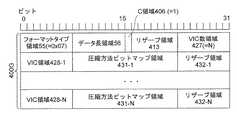
(3)VICテーブル127tに含まれるVICのうちの少なくとも1つの所定の必須の(マンダトリ)VICの映像データが第1、第2又は第3の圧縮方法で圧縮されているときに、シンク機器120が当該圧縮された映像データを伸張できるか否かを表すフラグデータを格納するC領域406。なお、本実施形態及び以下の各実施形態において、必須のVICは4k2k映像フォーマットのVIC(48,49,50,51及び52)である。
(4)将来の利用のために予約されたリザーブ領域407。
(5)シンク機器120がサポートする圧縮方法(コーデック)を表す8ビットのビットマップデータを格納する圧縮方法ビットマップ領域408。圧縮方法を表すビットマップデータのビット0は第1の圧縮方法に割り当てられ、ビット1は第2の圧縮方法に割り当てられ、ビット2は第3の圧縮方法に割り当てられている。ビット3からビット8は予備ビットである。圧縮方法を表すビットマップデータのビットの値が1にセットされているとき、当該ビットに対応する圧縮方法で圧縮された圧縮映像データをシンク機器120が伸張できることを示す一方、ビットの値が0にセットされているとき、当該ビットに対応する圧縮方法で圧縮された圧縮映像データをシンク機器120が伸張できないことを示す。Second embodiment.
FIG. 23 is a diagram showing a format of a compressed
(1) A
(2) A
(3) When the video data of at least one predetermined essential (mandatory) VIC among the VICs included in the VIC table 127t is compressed by the first, second, or third compression method, the sink device 120 C area 406 for storing flag data indicating whether or not the compressed video data can be decompressed. In this embodiment and each of the following embodiments, the essential VIC is a VIC (48, 49, 50, 51 and 52) in a 4k2k video format.
(4) A reserved area 407 reserved for future use.
(5) A compression method bitmap area 408 for storing 8-bit bitmap data representing a compression method (codec) supported by the
シンク機器120は、第1の実施形態係る圧縮映像情報メッセージ400を用いて、伸張できる圧縮映像データのVIC及び圧縮方法をソース機器110に通知できない。しかしながら、本実施形態によれば、圧縮映像情報メッセージ400はC領域406と圧縮方法ビットマップ領域408とを含むので、シンク機器120は、C領域406に格納されるフラグデータの値を1にセットすることにより、上述した必須のVICの映像データを第1〜第3の圧縮方法で圧縮した各圧縮映像データをそれぞれ伸張できるか否かを、ソース機器110に通知できる。 The
第3の実施形態.
図24は、本発明の第3の実施形態に係る圧縮映像情報メッセージ400Bのフォーマットを示す図である。本実施形態に係る圧縮映像情報メッセージBは、第2の実施形態に係る圧縮映像情報メッセージ400Aに比較して、圧縮方法ビットマップ408に格納されたビットマップデータによって示されたシンク機器120がサポートする圧縮方法で圧縮された圧縮映像データのうち、シンク機器120が伸張可能な圧縮映像データのVICをそれぞれ格納するVIC領域409−1,409−2,…,409−N(Nは1以上の整数である。)をさらに含むことを特徴としている。なお、図24において、C領域406は、VICテーブル127tに含まれるVICのうちの少なくとも1つのVICの第1、第2又は第3の圧縮方法で圧縮された圧縮映像データをシンク機器120が伸張できるときにフラグデータ(1)を格納し、VICテーブル127tに含まれる全てのVICの第1、第2又は第3の圧縮方法で圧縮された圧縮映像データをシンク機器120が伸張できないときにフラグデータ(0)を格納する。Third embodiment.
FIG. 24 is a diagram showing a format of a compressed
第2の実施形態では、シンク機器120は、圧縮映像情報メッセージ400Aを用いて、シンク機器120において伸張可能な必須のVICの圧縮映像データの圧縮方法のみをソース機器110に通知できたが、本実施形態によれば、シンク機器120は、圧縮映像情報メッセージ400Bを用いて、シンク機器120において伸張可能なVICテーブル127tに含まれる任意のVICの圧縮映像データの圧縮方法をソース機器110に通知することができる。 In the second embodiment, the
第4の実施形態.
図25は、本発明の第4の実施形態に係る圧縮映像情報メッセージ400Cのフォーマットを示す図である。本実施形態に係る圧縮映像情報メッセージ400Cは、第3の実施形態に係る圧縮映像情報メッセージ400Bに比較して、以下の点が異なる。
(1)リザーブ領域407及び圧縮方法ビットマップ領域408に代えて、将来の利用のために予約されたリザーブ領域410を含む。
(2)VIC領域409−1〜409−Nに代えて、N個のVIC領域411−n(n=1,2,…,N)と、各VIC領域411−nに対応して設けられた圧縮方法ビットマップ領域412−n(n=1,2,…,N)とを含む。Fourth embodiment.
FIG. 25 is a diagram showing a format of a compressed
(1) Instead of the reserved area 407 and the compression method bitmap area 408, a reserved area 410 reserved for future use is included.
(2) Instead of the VIC regions 409-1 to 409 -N, N VIC regions 411-n (n = 1, 2,..., N) and the VIC regions 411-n are provided correspondingly. Compression method bitmap area 412-n (n = 1, 2,..., N).
なお、図25において、C領域406は、シンク機器120が圧縮映像データを伸張できるときにフラグデータ(1)を格納し、伸張できないときにフラグデータ(0)を格納する。また、各圧縮方法ビットマップ領域412−nは、対応するVIC領域411−nに格納されたVICの圧縮映像データのシンク機器120がサポートする圧縮方法を表すビットマップデータを格納する。ここで、VIC領域411−nに格納されるビットマップデータは、図21及び図22の圧縮方法ビットマップ領域408に格納されるビットマップデータと同様に構成される。 In FIG. 25, the C area 406 stores flag data (1) when the
本実施形態に係る圧縮映像情報メッセージ400Cは、第3の実施形態に比較して、N組のVIC領域411−n及び圧縮方法ビットマップ領域412−nをさらに含むので、シンク機器120がVIC毎に異なる圧縮方法をサポートしている場合でも、シンク機器120がサポートする全ての圧縮映像データのVIC及び圧縮方法の組み合わせをソース機器110に通知できる。 Compared to the third embodiment, the compressed
第5の実施形態.
図26は、本発明の第5の実施形態に係る圧縮映像情報メッセージ400Dの、C領域に1が格納されかつ圧縮フォーマット数領域414に0が格納されたときのフォーマットを示す図である。また、図27は、本発明の第5の実施形態に係る圧縮映像情報メッセージ400Dの、C領域に1が格納され圧縮フォーマット数領域414にNが格納されたときのフォーマットを示す図である。図26及び図27において、圧縮映像情報メッセージ400Dは、図25の圧縮映像情報メッセージ400Cのフォーマットタイプ領域55と、データ長領域56と、C領域406とに加えて、以下の各領域を含む。Fifth embodiment.
FIG. 26 is a diagram showing a format when 1 is stored in the C area and 0 is stored in the compression format number area 414 of the compressed
(1)将来の利用のために予約されたリザーブ領域413。
(2)シンク機器120において伸張可能な圧縮映像データのVICと圧縮方法の組み合わせの総数Nを格納する圧縮フォーマット数領域414。
(3)N組のVIC領域415−n(n=1,2,…,N)と、各VIC領域415−nに対応して設けられた圧縮方法識別子領域416−n及びリザーブ領域417−n。ここで、VIC領域415−nは、シンク機器120において伸張可能な圧縮映像データのVICを格納する。また、圧縮方法識別子領域416−nは、VIC領域415−nに格納されたVICの圧縮映像データの圧縮方法のうちシンク機器120がサポートする圧縮方法を識別する圧縮方法識別子を格納する。(1) A reserved
(2) A compression format number area 414 for storing the total number N of combinations of VIC and compression methods of compressed video data that can be decompressed by the
(3) N sets of VIC areas 415-n (n = 1, 2,..., N), compression method identifier areas 416-n and reserved areas 417-n provided corresponding to the respective VIC areas 415-n. . Here, the VIC area 415-n stores a VIC of compressed video data that can be decompressed by the
ここで、圧縮方法識別子は以下のように定義される。
圧縮せず:圧縮方法識別子=0b0000;
第1の圧縮方法:圧縮方法識別子=0b0001;
第2の圧縮方法:圧縮方法識別子=0b0010;
第3の圧縮方法:圧縮方法識別子=0b0011;
圧縮方法識別子0b0100〜0b1111は将来のための予備の圧縮方法識別子である。Here, the compression method identifier is defined as follows.
Not compressed: compression method identifier = 0b0000;
First compression method: compression method identifier = 0b0001;
Second compression method: compression method identifier = 0b0010;
Third compression method: compression method identifier = 0b0011;
The compression method identifiers 0b0100 to 0b1111 are spare compression method identifiers for the future.
シンク機器120が圧縮映像データを伸張できない場合には、C領域406には0がセットされる。また、シンク機器120が所定の必須の圧縮方法で圧縮された上述した必須のVICの圧縮映像データのみを伸張できる場合には、図26に示すように、C領域406に1がセットされ、かつ圧縮フォーマット数領域414に0がセットされる。ここで、本実施形態及び以下の各実施形態において、必須の圧縮方法は第1の圧縮方法である。 If the
さらに、シンク機器120が必須の圧縮方法で圧縮された圧縮映像データ及びその他のオプションとして規定された第2又は第3の圧縮方法で圧縮された圧縮映像データを伸張できる場合には、図27に示すように、圧縮フォーマット数領域414は、1以上の整数Nを格納する。 Furthermore, when the
以上説明したように、本実施形態によれば、シンク機器120は、圧縮映像情報メッセージ400Dを用いて、圧縮映像データを伸張できること、及び、伸張可能な全ての圧縮映像データのVIC及び圧縮方法識別子の組み合わせを、ソース機器110に対して通知することができる。 As described above, according to the present embodiment, the
第6の実施形態.
図28は、本発明の第6の実施形態に係る圧縮映像情報メッセージ400Eの、CMM(Compression Method Multiple)領域418に0b01が格納されたときのフォーマットを示す図である。また、図29は、本発明の第6の実施形態に係る圧縮映像情報メッセージ400Eの、CMM領域418に0b11が格納されたときのフォーマットを示す図である。Sixth embodiment.
FIG. 28 is a diagram showing a format when 0b01 is stored in a CMM (Compression Method Multiple) area 418 of the compressed
本実施形態に係る圧縮映像情報メッセージ400Eは、第5の実施形態に係る圧縮映像情報メッセージ400Dに比較して、以下の点が異なる。
(1)リザーブ領域413に代えて、圧縮映像情報メッセージ400Eが以下のVICビットマップ領域426を含むか否かを表すデータを格納するCMM領域418と、リザーブ領域419とを含む。
(2)CMM領域418に0b01が格納されているときに圧縮方法識別子ビットマップ領域424及びリザーブ領域425をさらに含み、CMM領域418に0b11が格納されているときに圧縮方法識別子ビットマップ領域424、リザーブ領域425及びVICビットマップ領域426をさらに含むこと。The compressed
(1) Instead of the reserved
(2) It further includes a compression method identifier bitmap area 424 and a reserve area 425 when 0b01 is stored in the CMM area 418, and a compression method identifier bitmap area 424 when 0b11 is stored in the CMM area 418. Further include a reserve area 425 and a VIC bitmap area 426.
図28に示すようにCMM領域1101に0b01が格納された場合は、圧縮方法識別子ビットマップ領域424は、全てのVIC領域415−1〜415−Nに格納されるVICの圧縮映像データについて、共通にサポートされる圧縮方法を表すビットマップデータを格納する。ここで、圧縮方法識別子ビットマップ領域424に格納されるビットマップデータの各ビットには、上述した各圧縮方法識別子が割り当てられる。また、ビットマップデータのビットの値が1にセットされているとき、当該ビットに対応する圧縮方法がサポートされていることを示す一方、ビットの値が0にセットされているとき、当該ビットに対応する圧縮方法がサポートされていないことを示す。 As shown in FIG. 28, when 0b01 is stored in the CMM area 1101, the compression method identifier bitmap area 424 is common to the compressed video data of the VIC stored in all the VIC areas 415-1 to 415-N. Stores bitmap data representing the compression methods supported. Here, each compression method identifier described above is assigned to each bit of the bitmap data stored in the compression method identifier bitmap area 424. Further, when the bit value of the bitmap data is set to 1, it indicates that the compression method corresponding to the bit is supported, while when the bit value is set to 0, the bit is set to the bit. Indicates that the corresponding compression method is not supported.
また、図29に示すように、CMM領域1101に0b11が格納された場合は、圧縮映像情報メッセージ400EはVICビットマップ領域426をさらに含む。ここで、VICビットマップ領域426は、圧縮方法ビットマップ領域424に格納されたビットマップデータの1にセットされた各ビットに対応する各圧縮方法で圧縮された圧縮映像データについて、共通にサポートされるVICを表すビットマップデータを格納する。ここで、VICビットマップ領域426に格納されるビットマップデータの各ビットには、VICテーブル127tに含まれるVICの値(図2、図3及び図4参照)が降順に割り当てられる。このとき、シンク機器120は、図29の圧縮映像情報メッセージ400Eを用いて、VICビットマップ領域426内で1にセットされた各ビットに対応するVICの映像データに対して、圧縮方法ビットマップ領域424で1にセットされた各圧縮方法がサポートされることを、ソース機器110に通知する。 Also, as shown in FIG. 29, when 0b11 is stored in the CMM area 1101, the compressed
以上説明したように、本実施形態によれば、シンク機器120は、圧縮映像情報メッセージ400Eを用いて、シンク機器120がソース機器110に対して、圧縮映像データを伸張できること、及び、伸張可能な全ての圧縮映像データのVIC及び圧縮方法識別子の組み合わせを通知することができる。 As described above, according to the present embodiment, the
第7の実施形態.
図30は、本発明の第7の実施形態に係る圧縮映像情報メッセージ400Fのフォーマットを示す図である。本実施形態に係る圧縮映像情報メッセージ400Fは、第5の実施形態に係る圧縮映像情報メッセージ400D(図27参照。)に比較して、以下の点が異なる。
(1)圧縮フォーマット数領域414に代えて、シンク機器120において伸張可能な圧縮映像データのVICの総数Nを格納するVIC数領域427を含む。
(2)N組のVIC領域415−n、圧縮方法識別子領域416−n及びリザーブ領域417−nに代えて、シンク機器120において伸張可能な圧縮映像データのN個のVICをそれぞれ格納するVIC領域428−1,…,428−Nと、VIC領域428−1,…,428−Nに対応して設けられた圧縮方法識別子数領域429−1,…,429−Nと、各圧縮方法識別子数領域429−1,…,429−Nの後に設けられかつ各圧縮方法識別子数領域429−1,…,429−Nに格納された数M1,…,MNと同数の圧縮方法識別子領域430−1−1,…,430−1−M1,…,430−N−1,…,430−N−MNとを含む。Seventh embodiment.
FIG. 30 is a diagram showing a format of a compressed
(1) Instead of the compression format number area 414, a VIC number area 427 for storing the total number N of VICs of compressed video data that can be expanded in the
(2) VIC areas for storing N VICs of compressed video data that can be decompressed by the
図30において、VIC数領域427は、シンク機器120において伸張可能な圧縮映像データのVICの総数Nを格納する。また、VIC領域428−1,…,428−Nはそれぞれ、シンク機器120において伸張可能な圧縮映像データのVICを格納する。各圧縮方法識別子数領域429−n(n=1,2,…,N)は、後に続く圧縮方法識別子の数を示す値Mnを格納する。各圧縮方法識別子領域430−n−mn(m=1,2,…,M)は、VIC領域428−nに格納されたVICの圧縮映像データのうちシンク機器120がサポートする圧縮方法の圧縮方法識別子をそれぞれ格納する。なお、本実施形態において圧縮方法識別子は第5の実施形態と同様に定義される。 In FIG. 30, the VIC number area 427 stores the total number N of VICs of compressed video data that can be decompressed by the
以上説明したように、本実施形態によれば、シンク機器120は、圧縮映像情報メッセージ400Fを用いて、シンク機器120がソース機器110に対して、圧縮映像データを伸張できること、及び、伸張可能な全ての圧縮映像データのVIC及び圧縮方法識別子の組み合わせを通知することができる。 As described above, according to the present embodiment, the
第8の実施形態.
図31は、本発明の第8の実施形態に係る圧縮映像情報メッセージ400Gのフォーマットを示す図である。本実施形態に係る圧縮映像情報メッセージ400Gは、第7の実施形態に係る圧縮映像情報メッセージ400Fに比較して、圧縮方法識別子数領域429−n(n=1,2,…,N)及び圧縮方法識別子領域430−n−mn(m=1,2,…,M)に代えて、VIC領域428−1,…,428−Nに対応して設けられた圧縮方法ビットマップ領域431−1,…,431−N及びリザーブ領域432−1,…,432−Nを含む点が異なる。Eighth embodiment.
FIG. 31 is a diagram showing a format of a compressed
図31において、各圧縮方法ビットマップ領域431−n(n=1,2,…,N)は、VIC領域428−nに格納されたVICの圧縮映像データの圧縮方法のうちシンク機器120がサポートする圧縮方法を表すビットマップデータを格納する。圧縮方法ビットマップ領域431−nに格納されるビットマップデータは、図25の圧縮方法ビットマップ領域412−nと同様に構成される。 In FIG. 31, each compression method bitmap area 431-n (n = 1, 2,..., N) is supported by the
以上説明したように、本実施形態によれば、シンク機器120は、圧縮映像情報メッセージ400Gを用いて、シンク機器120がソース機器110に対して、圧縮映像データを伸張できること、及び、伸張可能な全ての圧縮映像データのVIC及び圧縮方法識別子の組み合わせを通知することができる。 As described above, according to the present embodiment, the
第9の実施形態.
図32は、本発明の第9の実施形態に係る圧縮映像情報メッセージ400Hのフォーマットを示す図である。本実施形態は第5の実施形態に係る圧縮映像情報メッセージ400Dに比較して、以下の点が異なる。
(1)圧縮フォーマット数領域414に代えて、シンク機器120において伸張可能な圧縮映像データの圧縮方法の総数Mを格納する圧縮方法数領域433を含む。
(2)N組のVIC領域415−n、圧縮方法識別子領域416−n及びリザーブ領域417−nに代えて、シンク機器120において伸張可能な圧縮映像データの圧縮方法の圧縮方法識別子をそれぞれ格納する圧縮方法識別子領域434−1,…,434−Mと、圧縮方法識別子領域434−1,…,434−Mに対応して設けられたリザーブ領域435−1,…,435−Mと、圧縮方法識別子領域434−1,…,434−Mに対応して設けられたVIC数領域436−1,…,436−Mと、各VIC数領域436−1,…,436−Mの後に設けられかつ各VIC数領域436−1,…,436−Mに格納された数M1,…,MNと同数のVIC領域437−1−1,…,437−1−M1,…,437−N−1,…,437−N−MNとを含む。Ninth embodiment.
FIG. 32 is a diagram showing a format of a compressed
(1) Instead of the compression format number area 414, a compression method number area 433 for storing the total number M of compression methods of compressed video data that can be decompressed by the
(2) Instead of the N sets of VIC areas 415-n, compression method identifier areas 416-n, and reserve areas 417-n, the compression method identifiers of compression methods of compressed video data that can be decompressed by the
図32において、圧縮方法数領域433は、シンク機器120において伸張可能な圧縮映像データの圧縮方法の総数Mを格納する。また、各圧縮方法識別子領域434−mは、シンク機器120において伸張可能な圧縮映像データの圧縮方法の第5の実施形態と同様に定義された圧縮方法識別子を格納する。各VIC数領域436−mは、対応する圧縮方法識別子領域434−mに格納された値に対応する圧縮方法によって圧縮された圧縮映像データのうちシンク機器120がサポートするVICの総数Mnを格納する。さらに、各VIC領域437−m−mnは、圧縮方法識別子領域434−mに格納された値に対応する圧縮方法によって圧縮された圧縮映像データのうちシンク機器120がサポートするVIC。 In FIG. 32, a compression method number area 433 stores the total number M of compression methods of compressed video data that can be decompressed by the
以上説明したように、本実施形態によれば、シンク機器120は、圧縮映像情報メッセージ400Hを用いて、シンク機器120がソース機器110に対して、圧縮映像データを伸張できること、及び、伸張可能な全ての圧縮映像データのVIC及び圧縮方法識別子の組み合わせを通知することができる。 As described above, according to the present embodiment, the
第10の実施形態.
図33は、本発明の第10の実施形態に係る圧縮映像情報メッセージ400Iのフォーマットを示す図である。本実施形態は第9の実施形態に係る圧縮映像情報メッセージ400Hに比較して、圧縮方法識別子領域434−m(m=1,2,…,M)に対応して設けられたリザーブ領域439−m及びVICビットマップ領域438−mを含む点が異なる。Tenth embodiment.
FIG. 33 is a diagram showing a format of a compressed video information message 400I according to the tenth embodiment of the present invention. Compared with the compressed
図33において、各VICビットマップ領域438−mは、対応する圧縮方法識別子領域434−mに格納された値に対応する圧縮方法によって圧縮された圧縮映像データのうちシンク機器120がサポートするVICを表すビットマップデータを格納する。ここで、VICビットマップ領域438−mに格納されるビットマップデータは、第6の実施形態のVICビットマップ領域426(図29参照。)に格納されるビットマップデータと同様に構成さる。 In FIG. 33, each VIC bitmap area 438-m indicates a VIC supported by the
以上説明したように、本実施形態によれば、シンク機器120は、圧縮映像情報メッセージ400Iを用いて、シンク機器120がソース機器110に対して、圧縮映像データを伸張できること、及び、伸張可能な全ての圧縮映像データのVIC及び圧縮方法識別子の組み合わせを通知することができる。 As described above, according to the present embodiment, the
第11の実施形態.
図34は、本発明の第11の実施形態に係る圧縮映像情報メッセージ400Jのフォーマットを示す図である。本実施形態は第5の実施形態に係る圧縮映像情報メッセージ400Dに比較して、以下の点が異なる。
(1)圧縮フォーマット数領域414に代えて、シンク機器120において伸張可能な圧縮映像データの圧縮方法とVICとの組み合わせの総数Lを格納する圧縮映像フォーマット識別子数領域439を含む。
(2)N組のVIC領域415−n、圧縮方法識別子領域416−n及びリザーブ領域417−nに代えて、圧縮方法とVICとの組み合わせを識別する圧縮映像フォーマット識別子(以下、圧縮VICという。)をそれぞれ格納する圧縮映像フォーマット識別子数領域440−1,…,440−Lを含むこと。Eleventh embodiment.
FIG. 34 is a diagram showing a format of a compressed
(1) Instead of the compressed format number area 414, a compressed video format
(2) Instead of N sets of VIC areas 415-n, compression method identifier areas 416-n, and reserve areas 417-n, compressed video format identifiers (hereinafter referred to as compression VICs) for identifying combinations of compression methods and VICs. ), Each of which includes a compressed video format identifier number area 440-1,.
本実施形態において、圧縮方法とVICとの組み合わせ毎に1つの圧縮VICを割り当てる。本実施形態において、圧縮VICは以下のように定義される。
圧縮VIC=「1」:圧縮方法は第1の圧縮方法でありVICは48(3840x2160p、23.97/24Hz)である。
圧縮VIC=「2」:圧縮方法は第1の圧縮方法でありVICは49(3840x2160p、25Hz)である。
圧縮VIC=「3」:圧縮方法は第1の圧縮方法でありVICは50(3840x2160p、29.97/30Hz)である。
圧縮VIC=「4」:圧縮方法は第1の圧縮方法でありVICは51(4096x2160p、23.97/24Hz)である。
圧縮VIC=「5」:圧縮方法は第1の圧縮方法でありVICは52(4096x2160p、25Hz)である。In the present embodiment, one compression VIC is assigned for each combination of compression method and VIC. In the present embodiment, the compressed VIC is defined as follows.
Compression VIC = “1”: The compression method is the first compression method, and the VIC is 48 (3840 × 2160p, 23.97 / 24 Hz).
Compression VIC = “2”: The compression method is the first compression method, and the VIC is 49 (3840 × 2160p, 25 Hz).
Compression VIC = “3”: The compression method is the first compression method, and VIC is 50 (3840 × 2160p, 29.97 / 30 Hz).
Compression VIC = “4”: The compression method is the first compression method, and the VIC is 51 (4096 × 2160p, 23.97 / 24 Hz).
Compression VIC = “5”: The compression method is the first compression method, and the VIC is 52 (4096 × 2160p, 25 Hz).
シンク機器120は、上記圧縮VICのうち、サポートするL個の圧縮VICの値を圧縮VIC領域440−1,…,440−Lにそれぞれ格納する。 The
また、圧縮VICを図2、図3及び図4のVICとして定義しなおしてもよい。例えば、VICの48から52を、第1の圧縮方法で圧縮された映像データのVICにそれぞれ割り当ててもよい。例えば、圧縮映像データのVICとしては以下のように割り当ててもよい。 Further, the compressed VIC may be redefined as the VIC in FIGS. 2, 3, and 4. For example,
VIC=「48」:3840x2160p、23.97/24Hz、第1の圧縮方法;
VIC=「49」:3840x2160p、25Hz、第1の圧縮方法;
VIC=「50」:3840x2160p、29.97/30Hz、第1の圧縮方法;
VIC=「51」:4096x2160p、23.97/24Hz、第1の圧縮方法;
VIC=「52」:4096x2160p、25Hz、第1の圧縮方法。VIC = “48”: 3840 × 2160p, 23.97 / 24 Hz, first compression method;
VIC = “49”: 3840 × 2160p, 25 Hz, first compression method;
VIC = “50”: 3840 × 2160p, 29.97 / 30 Hz, first compression method;
VIC = “51”: 4096 × 2160p, 23.97 / 24 Hz, first compression method;
VIC = “52”: 4096 × 2160p, 25 Hz, first compression method.
この場合、シンク機器120は第1の圧縮方法をサポートしている場合、デバイス能力応答メッセージ2内の映像情報メッセージ200に含まれるVIC領域207−1,207−2,…,208−N(図13参照。)に48から52までの値をそれぞれ格納し、ソース機器110に送信する。ソース機器110は、デバイス能力応答メッセージ2内の映像情報メッセージ200のVIC領域207−1,207−2,…,208−Nに48から52が格納されていることを検出し、ソース機器110からシンク機器120に第1の圧縮方法で圧縮されたコンテンツデータの圧縮映像データを送信する。 In this case, when the
以上説明したように、本実施形態によれば、シンク機器120は、圧縮映像情報メッセージ400Jを用いて、シンク機器120がソース機器110に対して、圧縮映像データを伸張できること、及び、伸張可能な全ての圧縮映像データのVIC及び圧縮方法識別子の組み合わせを通知することができる。 As described above, according to the present embodiment, the
第12の実施形態.
図35は、本発明の第12の実施形態に係る詳細タイミング情報メッセージ300Aのフォーマットを示す図である。また、図36は、本発明の第12及び第13の実施形態において用いられる4k2k映像フォーマットのVICと各タイミング値との関係を示す表である。なお、図36の4つのVICは、図2〜図4のVICテーブル115t及び127tの予備のVICに割り当てられている。また、図36の各タイミング値は、ソース機器110とシンク機器120との間又はシンク機器120内の各IC(Integrated Circuit)間で4k2k映像データを伝送するときに用いられる。本実施形態に係る詳細タイミング情報メッセージ300Aは、第1の実施形態に係る詳細タイミング情報メッセージ300(図14参照。)に比較して、リザーブ領域301に代えて拡張領域325とリザーブ領域326とを含み、リザーブ領域306に代えて水平有効期間上位ビット領域327を含む点が異なる。Twelfth embodiment.
FIG. 35 is a diagram showing a format of a detailed
図35において、拡張領域325は、水平有効期間Hactiveの有効画素数を格納する水平有効期間領域305を水平有効期間上位ビット領域327まで拡張するか否か(水平有効期間上位ビット領域327に格納されたデータが有効か否か)を表すデータを格納する。拡張領域325に0が格納されたときは、水平有効期間領域305は水平有効期間上位ビット領域327まで拡張されず、水平有効期間領域305は水平有効期間Hactiveの有効画素数を12ビットのデータとして格納し、水平有効期間上位ビット領域327に格納されるデータは無視される。一方、拡張領域325に1が格納されたときは、水平有効期間領域305は水平有効期間上位ビット領域327まで拡張され、水平有効期間領域305は水平有効期間Hactiveの有効画素数の下位12ビットのデータを格納し、水平有効期間上位ビット領域327は水平有効期間Hactiveの有効画素数の上位4ビットのデータを格納する。 In FIG. 35, the extension area 325 indicates whether or not the horizontal effective period area 305 storing the number of effective pixels in the horizontal effective period Hactive is extended to the horizontal effective period upper bit area 327 (stored in the horizontal effective period upper bit area 327). Data representing whether or not the data is valid). When 0 is stored in the extension area 325, the horizontal effective period area 305 is not extended to the horizontal effective period
第1の実施形態に係る詳細タイミング情報メッセージ300によれば、水平有効期間領域301のサイズは12ビットであるので、シンク機器120はソース機器110に対して、0ピクセルから4095ピクセルまでの値を有する水平有効期間Hactiveの有効画素数しか通知できなかった。このため、図36のVIC(D)の4k2k映像フォーマットのように水平有効期間の有効画素数が4096であるときには、当該有効画素数を、詳細タイミング情報メッセージ300を用いてシンク機器120からソース機器110に通知できなかった。しかしながら、本実施形態によれば、4096を2進数で表現した13ビットの数値「1000000000000(下位12ビットが0である。)」の下位12ビットの数値「000000000000(12個の0である。)」は水平有効期間領域305に格納され、上位ビットの数値「0001(上位3ビットが0で、最下位ビットが1)」は水平有効期間上位ビット領域327に格納される。このため、本実施形態によれば、水平有効期間Hactiveの有効画素数のビット数が13ビット以上であっても、シンク機器120はソース機器110に当該有効画素数を通知できる。 According to the detailed
第13の実施形態.
図37は、本発明の第13の実施形態に係る詳細タイミング情報メッセージ300Bのフォーマットを示す図である。また、図38は、図37の拡張領域ID領域331−1〜331−Jに格納される拡張領域IDと領域名との関係を示す表である。本実施形態に係る詳細タイミング情報メッセージ300Bは、第1の実施形態に係る詳細タイミング情報メッセージ300(図14参照。)に比較して、以下の点が異なる。
(1)リザーブ領域301に代えて、詳細タイミング情報メッセージ300Bの領域304,305,307,309,311,313,314,315,316,317,319,321,322,323のうちの少なくとも1つの領域が拡張されるときに1を格納する一方、全ての領域304,305,307,309,311,313,314,315,316,317,319,321,322,323が拡張されないときに0を格納する拡張領域328と、リザーブ領域326とを含む。
(2)リザーブ領域303に代えて、詳細タイミング情報を格納する領域304,305,307,309,311,313,314,315,316,317,319,321,322,323のうち拡張される領域の数J(Jは1以上の整数である。)を格納する拡張領域数領域329とリザーブ領域330とを含む。
(3)拡張される領域のIDを格納する拡張領域ID領域331−j(j=1,2,…,J)と、拡張領域ID領域331−jに対応して設けられ、かつ拡張される領域に格納されるデータの上位ビットのデータを格納する拡張領域上位ビット領域332−jとをさらに含む。
(4)詳細タイミング情報メッセージ300Bのメッセージ長を32ビットの整数倍に揃えるためのパディングビット領域333をさらに含む。Thirteenth embodiment.
FIG. 37 is a diagram showing a format of the detailed
(1) Instead of the reserve area 301, at least one of the
(2) Instead of the reserved area 303, an area to be expanded among the
(3) An extended area ID area 331-j (j = 1, 2,..., J) for storing the ID of the area to be extended and an extended area ID area 331-j are provided and extended. It further includes an extended area upper bit area 332-j for storing upper bit data of the data stored in the area.
(4) It further includes a padding bit area 333 for aligning the message length of the detailed
図38に示すように、領域304,305,307,309,311,313,314,315,316,317,319,321,322,323には、固有の拡張領域ID1〜14がそれぞれ割り当てられている。 As shown in FIG. 38, the
シンク機器120が図36のVIC(D)の詳細タイミング情報を、詳細タイミング情報メッセージ300Bを用いてソース機器110に送信するときの、図1の無線通信システムの動作を説明する。この場合、拡張されるべき領域は、水平有効期間Hactiveの有効画素数(4096である。)を格納する水平有効期間領域305のみである。このとき、拡張領域328は1を格納し、拡張領域数領域329は1を格納し、拡張領域ID領域331−1は拡張領域ID2(図38参照。)を格納する。さらに、水平有効期間領域305は、4096を2進数で表現した13ビットの数値「1000000000000(下位12ビットが0である。)」の下位12ビットの数値「000000000000(12個の0である。)」を格納し、拡張領域上位ビット領域332−1は、4096を2進数で表現した13ビットの数値の上位ビットの数値「000000000001(上位11ビットが0であり、最下位ビットが1である。)」を格納する。従って、シンク機器120は、詳細タイミング情報メッセージ300Bを用いて、水平有効期間Hactiveの有効画素数を、24ビットのデータ「000000000001000000000000(上位11ビットが0であり、12ビット目が1であり、下位12ビットが0である。)」としてソース機器110に送信できる。 The operation of the wireless communication system of FIG. 1 when the
第12の実施形態に係る詳細タイミング情報メッセージ300Aでは、水平有効期間領域305のみが拡張された。しかしながら、水平同期オフセット領域313のサイズは10ビットであるので、シンク機器120はソース機器110に対して、0ピクセルから1023ピクセルまでの値を有する水平同期パルス前駆期間(水平同期オフセット期間)Hfrontの画素数しか通知できなかった。本実施形態は、第12の実施形態に比較して、詳細タイミング情報を格納する全ての領域304,305,307,309,311,313,314,315,316,317,319,321,322,323を拡張できるという特有の作用効果を有する。 In the detailed
第14の実施形態.
図39は、本発明の第14の実施形態において、図11の入力フォーマット情報メッセージ5のフォーマットタイプ領域55に格納される値とフォーマットタイプとの関係を示す表である。また、図40は、本発明の第14の実施形態に係る拡張詳細タイミング情報メッセージ700のフォーマットを示す図である。図39に示すように、本実施形態は、第1の実施形態(図12参照。)に比較して、入力フォーマット情報メッセージ5のフォーマットタイプ領域55に格納されるフォーマットタイプのデータに、拡張詳細タイミング情報(EXTENDED_DETAILED_TIMING_INFO)を表す値(0x08)を追加したことを特徴としている。ここで、本実施形態において、拡張詳細タイミング情報に対応する値(0x08)を格納するフォーマットタイプ領域55を含むフォーマットデータメッセージ54を、拡張詳細タイミング情報メッセージ7000という。Fourteenth embodiment.
FIG. 39 is a table showing the relationship between values stored in the
図40において、拡張詳細タイミング情報メッセージ700は、以下の各領域を含む。
(1)拡張詳細タイミング情報に対応する値(0x08)を格納するフォーマットタイプ領域55。
(2)拡張詳細タイミング情報メッセージ700からフォーマットタイプ領域55とデータ長領域56とを除いた領域のデータ長を表すデータを格納するデータ長領域56。
(3)将来のために予約されたリザーブ領域701。
(4)拡張詳細タイミング情報のID番号を格納するID領域702。
(5)映像データのスキャン方法がインタレーススキャン及びプログレッシブスキャンのうちのいずれであるかを示すビットデータを格納するIP領域703。
(6)将来のために予約されたリザーブ領域704。
(7)映像データのリフレッシュレート(フィールドレート)を0.01Hzの単位で表した値を格納するリフレッシュレート領域705。
(8)水平有効期間Hactiveの有効画素数を格納する水平有効期間領域706。
(9)垂直有効期間Vactiveの有効画素数を格納する垂直有効期間領域707。
なお、領域705〜707はそれぞれ、16ビットのサイズを有する。In FIG. 40, the extended detailed timing information message 700 includes the following areas.
(1) A
(2) A
(3) A reserved area 701 reserved for the future.
(4) An
(5) An IP area 703 for storing bit data indicating whether the video data scanning method is interlaced scanning or progressive scanning.
(6) A reserved area 704 reserved for the future.
(7) A refresh rate area 705 for storing a value representing the refresh rate (field rate) of the video data in units of 0.01 Hz.
(8) A horizontal effective period area 706 that stores the number of effective pixels of the horizontal effective period Hactive.
(9) A vertical effective period area 707 for storing the number of effective pixels in the vertical effective period Vactive.
Each of the areas 705 to 707 has a size of 16 bits.
第12の実施形態では、第1の実施形態に係る詳細タイミング情報メッセージ300の水平有効期間領域305を拡張することにより、4k2k映像フォーマットの詳細タイミング情報を送信した。また、第13の実施形態では、第1の実施形態に係る詳細タイミング情報メッセージ300の領域304,305,307,309,311,313,314,315,316,317,319,321,322,323のうちの任意の領域を拡張することにより、4k2k映像フォーマットの詳細タイミング情報を送信した。本実施形態は、第12及び第13の実施形態に比較して、リフレッシュレートと、水平有効期間Hactiveの有効画素数と、垂直有効期間Vactiveの有効画素数とをそれぞれ16ビットのデータとしてシンク機器120からソース機器110に通知するための拡張詳細タイミング情報フォーマット700を新たに定義した点が異なる。図36に示すように、4k2k映像データのリフレッシュレートと、水平有効期間Hactiveの有効画素数と、垂直有効期間Vactiveの有効画素数とを16ビットの数値でそれぞれ表現できるので、本実施形態によれば、4k2k映像データのリフレッシュレートと、水平有効期間Hactiveの有効画素数と、垂直有効期間Vactiveの有効画素数とをシンク機器120からソース機器110に送信できる。 In the twelfth embodiment, the detailed timing information in the 4k2k video format is transmitted by extending the horizontal effective period region 305 of the detailed
第15の実施形態.
図41は、本発明の第15の実施形態において、図11の入力フォーマット情報メッセージ5のフォーマットタイプ領域55に格納される値とフォーマットタイプとの関係を示す表である。また、図42は、本発明の第15の実施形態に係る拡張解像度詳細タイミング情報メッセージ800のフォーマットを示す図である。図41に示すように、本実施形態は、第1の実施形態(図12参照。)に比較して、入力フォーマット情報メッセージ5のフォーマットタイプ領域55に格納されるフォーマットタイプのデータから圧縮映像情報の値を削除し、拡張解像度詳細タイミング情報(EXTENDED_RESOLUTION_DETAILED_TIMING_INFO)を表す値(0x07)を追加したことを特徴としている。ここで、本実施形態において、拡張解像度詳細タイミング情報に対応する値(0x07)を格納するフォーマットタイプ領域55を含むフォーマットデータメッセージ54を、拡張解像度詳細タイミング情報メッセージ800という。Fifteenth embodiment.
FIG. 41 is a table showing the relationship between values stored in the
図42において、拡張解像度詳細タイミング情報メッセージ800は、以下の各領域を含む。
(1)拡張解像度詳細タイミング情報に対応する値(0x07)を格納するフォーマットタイプ領域55。
(2)拡張解像度詳細タイミング情報メッセージ800からフォーマットタイプ領域55とデータ長領域56とを除いた領域のデータ長を表すデータを格納するデータ長領域56。
(3)将来のために予約されたリザーブ領域801。
(4)拡張解像度詳細タイミング情報のID番号を格納するID領域802。
(5)将来のために予約されたリザーブ領域803。
(6)ピクセルクロック周波数を格納するピクセルクロック領域804。
(7)水平有効期間Hactiveの有効画素数を格納する水平有効期間領域805。
(8)水平ブランキング期間(ブランク期間)Hblankの画素数を格納する水平ブランキング期間領域806。
(9)水平同期パルス前駆期間Hfrontの長さを画素数で表した値を格納する水平同期ブランキングフロント領域807。
(10)水平同期パルスHsyncのパルス幅を画素数で表した値を格納する水平同期パルス幅領域808。
(11)水平同期パルス後駆期間Hbackの長さを画素数で表した値を格納する水平同期ブランキングバック領域809。
(12)将来のために予約されたリザーブ領域810。
(13)垂直有効期間Vactiveの有効画素数を格納する垂直有効期間領域811。
(14)垂直ブランキング期間Vblankの画素数を格納する垂直ブランキング期間領域812。
(15)垂直同期パルス前駆期間Vfrontの長さを画素数で表した値を格納する垂直同期ブランキングフロント領域813。
(16)垂直同期パルスVsyncのパルス幅を画素数で表した値を格納する垂直同期パルス幅領域814。
(17)垂直同期パルス後駆期間Vbackの長さを画素数で表した値を格納する垂直同期ブランキングバック領域815。
(18)将来のために予約されたリザーブ領域816。
(19)画像の水平方向のサイズをミリメートル単位で表した値を格納する水平画像サイズ領域817。
(20)画像の垂直方向のサイズをミリメートル単位で表した値を格納する垂直画像サイズ領域818。
(21)水平方向の境界を表すデータを格納する水平境界領域819。
(22)垂直方向の境界を表すデータを格納する垂直境界領域820。
(23)ステレオ映像に関わる情報を格納するフラグ領域821。
(24)将来の利用のために予約されたリザーブ領域822。
なお、領域804〜822はそれぞれ、16ビットのサイズを有する。In FIG. 42, the extended resolution detailed timing information message 800 includes the following areas.
(1) A
(2) A
(3) A reserved area 801 reserved for the future.
(4) An
(5) A reserved area 803 reserved for the future.
(6) A pixel clock area 804 for storing the pixel clock frequency.
(7) A horizontal effective period area 805 that stores the number of effective pixels of the horizontal effective period Hactive.
(8) Horizontal blanking period (blank period) A horizontal blanking period area 806 for storing the number of pixels of Hblank.
(9) A horizontal synchronization blanking front area 807 that stores a value representing the length of the horizontal synchronization pulse precursor period Hfront by the number of pixels.
(10) A horizontal synchronization pulse width region 808 that stores a value representing the pulse width of the horizontal synchronization pulse Hsync in terms of the number of pixels.
(11) A horizontal synchronization blanking back area 809 that stores a value representing the length of the horizontal synchronization pulse follow-up period Hback in terms of the number of pixels.
(12) A reserved area 810 reserved for the future.
(13) A vertical effective period area 811 for storing the number of effective pixels in the vertical effective period Vactive.
(14) A vertical blanking period region 812 that stores the number of pixels in the vertical blanking period Vblank.
(15) A vertical synchronization blanking front area 813 for storing a value representing the length of the vertical synchronization pulse precursor period Vfront by the number of pixels.
(16) A vertical synchronization pulse width region 814 that stores a value representing the pulse width of the vertical synchronization pulse Vsync in terms of the number of pixels.
(17) A vertical synchronization blanking back area 815 for storing a value representing the length of the vertical synchronization pulse follower period Vback in terms of the number of pixels.
(18) A reserved area 816 reserved for the future.
(19) A horizontal image size area 817 for storing a value representing the horizontal size of the image in millimeters.
(20) A vertical image size area 818 for storing a value representing the vertical size of the image in millimeters.
(21) A horizontal boundary area 819 for storing data representing a horizontal boundary.
(22) A vertical boundary region 820 for storing data representing a vertical boundary.
(23) A flag area 821 for storing information related to stereo video.
(24) A reserved area 822 reserved for future use.
Each of the regions 804 to 822 has a size of 16 bits.
第12の実施形態では、第1の実施形態に係る詳細タイミング情報メッセージ300の水平有効期間領域305を拡張することにより、4k2k映像フォーマットの詳細タイミング情報を送信した。また、第13の実施形態では、第1の実施形態に係る詳細タイミング情報メッセージ300の領域304,305,307,309,311,313,314,315,316,317,319,321,322,323のうちの任意の領域を拡張することにより、4k2k映像フォーマットの詳細タイミング情報を送信した。本実施形態は、第12及び第13の実施形態に比較して、映像データのすべてのタイミング情報を、16ビットのデータとしてシンク機器120からソース機器110に通知するための拡張解像度詳細タイミング情報フォーマット700を新たに定義した点が異なる。 In the twelfth embodiment, the detailed timing information in the 4k2k video format is transmitted by extending the horizontal effective period region 305 of the detailed
従って、本実施形態によれば、映像データのタイミング情報をそれぞれ格納する各領域804〜821のサイズを16ビットに設定したので、各領域804〜821は、0から65535までの間の値を格納できる。このため、図36に示すように、4k2k映像データの全ての詳細タイミング情報をシンク機器120からソース機器110に送信できる。 Therefore, according to the present embodiment, the size of each of the areas 804 to 821 for storing the timing information of the video data is set to 16 bits, so that each of the areas 804 to 821 stores a value between 0 and 65535. it can. For this reason, as shown in FIG. 36, all the detailed timing information of 4k2k video data can be transmitted from the
なお、本実施形態において、第1の実施形態(図12参照。)に比較して、入力フォーマット情報メッセージ5のフォーマットタイプ領域55に格納されるフォーマットタイプのデータから圧縮映像情報の値を削除し、拡張解像度詳細タイミング情報を表す値(0x07)を追加した。しかしながら、本発明はこれに限らず、第1の実施形態(図12参照。)に比較して、入力フォーマット情報メッセージ5のフォーマットタイプ領域55に格納されるフォーマットタイプのデータから圧縮映像情報の値を削除せずに、拡張解像度詳細タイミング情報を表す値(例えば、0x08である。)を追加してもよい。 In this embodiment, compared with the first embodiment (see FIG. 12), the value of the compressed video information is deleted from the format type data stored in the
第16の実施形態.
図43は、本発明の第16の実施形態に係る圧縮映像フォーマット領域600Aのフォーマットを示す図である。また、図44は、図43のC_ID領域604に格納される値と圧縮方法との関係を示す表である。図43において、圧縮映像フォーマット領域600Aは以下の各領域を含む。
(1)圧縮映像フォーマット情報に対応する値(0x07)を格納するフォーマットタイプ領域91。
(2)バージョン番号0x01を格納するバージョン領域92。
(3)以下の領域604〜605の総データ長を表すデータを格納するデータ長領域93。
(4)送信する映像データの圧縮方法を示す図44において定義された値を格納するC_ID領域604。
(5)将来のために予約されたリザーブ領域605。Sixteenth embodiment.
FIG. 43 is a diagram showing a format of the compressed
(1) A format type area 91 for storing a value (0x07) corresponding to the compressed video format information.
(2) A version area 92 for storing the version number 0x01.
(3) A data length area 93 for storing data representing the total data length of the following
(4) A
(5) A reserved area 605 reserved for the future.
第1の実施形態に比較して、本実施形態にかかるソース機器110は、圧縮映像フォーマット領域600に代えて圧縮映像フォーマット領域600Aを含むストリーム開始通知メッセージ8を、シンク機器120に送信する。このとき、ソース機器110は、創始する映像データの圧縮方法を示す値をC_ID領域604に格納する。シンク機器120は、ストリーム開始通知メッセージ8を受信し、受信されたストリーム開始通知メッセージ8のC_ID領域604に基づいて、ソース機器110から圧縮されていない映像データと、第1の圧縮方法で圧縮された圧縮映像データと、第2の圧縮方法で圧縮された圧縮映像データと、第3の圧縮方法で圧縮された圧縮映像データとのうちのずれが送信されるのかをあらかじめ識別する。 Compared to the first embodiment, the source device 110 according to the present embodiment transmits a stream
従って、本実施形態によれば、ソース機器110は、シンク機器120に対して圧縮映像フォーマット領域600Aを含むストリーム開始通知メッセージ8を送ることにより、シンク機器120に対して送信する映像データの圧縮方法を通知できる。 Therefore, according to the present embodiment, the source device 110 transmits a stream
第17の実施形態.
図45は、ソース機器110がシンク機器120に対してフォーマット情報を要求しないときの、シンク機器120によってイニシエートされる本発明の第17の実施形態に係る機器接続処理を示すシーケンス図である。また、図46は、ソース機器110がシンク機器120に対してフォーマット情報を要求するときの、シンク機器120によってイニシエートされる本発明の第17の実施形態に係る機器接続処理を示すシーケンス図である。本実施形態は、第1の実施形態に比較して、シンク機器120が機器接続処理をイニシエートしたことを特徴としている。Seventeenth embodiment.
FIG. 45 is a sequence diagram showing device connection processing according to the seventeenth embodiment of the present invention initiated by the
シンク機器120が機器接続処理をイニシエートするときは、シンク機器120は、シンクポート番号を含む接続要求メッセージ6Aをソース機器110に送信して、ソース機器110に対してシンクポート番号を通知しかつソースポート及びAVデータ伝送のための帯域の予約を要求する。ここで、接続要求メッセージ6Aに含まれるSビットは1に設定され、接続要求メッセージ6Aに含まれるポート領域はシンクポート番号を格納する。 When the
図45に示すように、機器接続処理の前にシンク機器120がソース機器110からデバイス能力要求メッセージ1を受信し、当該デバイス能力要求メッセージ1内のFCビットに1がセットされているときは、シンク機器120は、ソース機器110が高速接続機能をサポートしていることを、機器接続処理の前に予め識別している。この場合、シンク機器120は、シンク機器120がサポートするフォーマットを接続要求メッセージ6Aに追加する。すなわち、接続要求メッセージ6Aは、図9のデバイス能力応答メッセージ2と同様に、映像情報メッセージ200と、詳細タイミング情報メッセージ300と、圧縮映像情報メッセージ400を含む入力フォーマット情報メッセージ5と、デバイス情報メッセージ3とを含む。一方、図45において、機器接続処理の前にシンク機器120がソース機器110からデバイス能力要求メッセージ1を受信し、当該デバイス能力要求メッセージ1内のFCビットに0がセットされているときは、シンク機器120は、ソース機器110が高速接続機能をサポートしていないことを、機器接続処理の前に予め識別している。この場合、シンク機器120は、接続要求メッセージ6Aの総データ長領域にゼロを格納する。 As shown in FIG. 45, when the
接続要求メッセージ6Aを受信した後に、ソース機器110は、シンク機器120からの接続要求を受け入れるときには、シンクポートを用いるAVデータ伝送のためのソースポートを予約する。ソース機器110は、ソースポートの予約処理を正常に終了すると、「成功」を表すデータを格納した結果コード領域を含む接続応答メッセージ7Aをシンク機器120に送信し、帯域予約処理を行う。また、ソース機器110は、シンク機器120に対してサポートするフォーマットの情報を要求するときには、図46に示すように、接続応答メッセージ7AのRFビットに1をセットする。シンク機器120は、接続応答メッセージ7AのRFビットに1がセットされているときには、シンク機器120がサポートするフォーマットの情報を含むデバイス能力応答メッセージ2を、ソース機器110に送信する。 After receiving the connection request message 6A, when the source device 110 accepts a connection request from the
なお、ソース機器110は、シンク機器120からの接続要求を拒否するときは、接続応答メッセージ7Aの結果コード領域に適切な理由を有する「失敗」を表すデータを格納する。 When the source device 110 rejects the connection request from the
さらに、ソース機器110は、帯域予約処理を正常に終了すると、「成功」を表すデータを格納した結果コード領域82を含むストリーム開始通知メッセージ8をシンク機器120に送信する一方、帯域予約処理に失敗すると、「失敗」を表すデータを格納した結果コード領域82を含むストリーム開始通知メッセージ8をシンク機器120に送信する。HRPストリームが割り当てられると、ソース機器110は、シンク機器120から当該シンク機器120がデータを有するHRPストリームのHRPパケットを受信する準備ができたことを表すACK信号を受信するまで、PHYヘッダ及びMACヘッダのみを含むHRPパケットをシンク機器120に無線送信する。ソース機器110は、上記ACK信号を受信すると、HRPパケットにAVデータを挿入してシンク機器120に無線送信する。 Further, when the bandwidth reservation processing is normally completed, the source device 110 transmits the stream
本実施形態は、第1の実施形態と同様の特有の作用効果を奏する。 This embodiment has the same specific operational effects as the first embodiment.
第18の実施形態.
図47及び図48は、本発明の第18の実施形態に係るVICテーブル115t及び127tを示す表である。本実施形態は、第1の実施形態に比較して、VICの割り当て方のみが異なる。本実施形態において、48から52の各VICは、4k2k映像フォーマットに対して、以下のように割り当てられている。Eighteenth embodiment.
47 and 48 are tables showing the VIC tables 115t and 127t according to the eighteenth embodiment of the present invention. This embodiment differs from the first embodiment only in the way of assigning VICs. In the present embodiment, each VIC from 48 to 52 is assigned as follows to the 4k2k video format.
(a)VICの44は、3840ピクセルの有効水平画素数と、2160ピクセルの有効垂直画素数と、プログレッシブスキャンである走査方法と、23.97Hz又は24Hzのフィールドレートとを有する4k2k映像フォーマットに割り当てられている。
(b)VICの45は、3840ピクセルの有効水平画素数と、2160ピクセルの有効垂直画素数と、プログレッシブスキャンである走査方法と、25Hzのフィールドレートとを有する4k2k映像フォーマットに割り当てられている。
(c)VICの46は、3840ピクセルの有効水平画素数と、2160ピクセルの有効垂直画素数と、プログレッシブスキャンである走査方法と、29.97Hz又は30Hzのフィールドレートとを有する4k2k映像フォーマットに割り当てられている。
(d)VICの47は、4096ピクセルの有効水平画素数と、2160ピクセルの有効垂直画素数と、プログレッシブスキャンである走査方法と、23.97Hz又は24Hzのフィールドレートとを有する4k2k映像フォーマットに割り当てられている。
(e)VICの48は、4096ピクセルの有効水平画素数と、2160ピクセルの有効垂直画素数と、プログレッシブスキャンである走査方法と、25Hzのフィールドレートとを有する4k2k映像フォーマットに割り当てられている。(A)
(B)
(C)
(D)
(E)
本実施形態は、第1の実施形態と同様の特有の作用効果を奏する。 This embodiment has the same specific operational effects as the first embodiment.
なお、上記各実施形態において示したメッセージの各フォーマットは一例にすぎず、メッセージ内に同様の領域が含まれていれば各領域の配置順序及びサイズなどを変更してもよい。 Note that each format of the message shown in each of the above embodiments is merely an example, and if the same area is included in the message, the arrangement order and size of each area may be changed.
また、上記各実施形態において、帯域管理部121bはシンク機器120に設けられたが、本発明はこれに限らず、ソース機器110又は他の機器に設けられてもよい。 In each of the above embodiments, the
また、上記各実施形態において、図2〜図4のVICテーブル又は図47〜図48のVICテーブルを用いたが、本発明はこれに限らず、4k2k映像フォーマットを識別するVICを含むVICテーブルであればよい。In each of the above embodiments, the VIC table of FIGS. 2 to 4 or the VIC table of FIGS. 47 to 48 is used. However, the present invention is not limited to this, and is a VIC table including a VIC for identifying a 4k2k video format. I just need it.
以上詳述したように、本発明に係る映像データの伝送方法、当該映像データを送信するソース機器、当該映像データを受信するシンク機器、並びに当該ソース機器及びシンク機器を備えた無線通信システムによれば、シンク機器は、シンク機器において表示可能な映像データの映像フォーマットを識別する少なくとも1つの映像フォーマット識別コードを含む映像情報メッセージと、(b)映像データを圧縮するための圧縮用パラメータを含む圧縮映像情報メッセージとを含むデバイス能力応答メッセージをソース機器に無線送信する一方、ソース機器は、送信する第1の映像データの映像フォーマットを識別する映像フォーマット識別コードと、第1の映像データが圧縮されているか否かを示すデータとを含むストリーム開始通知メッセージを、シンク機器に無線送信した後に、第1の映像データを上記シンク機器に無線送信し、第1の映像データの映像フォーマットを識別する映像フォーマット識別コードは、3840ピクセル又は4096ピクセルの有効水平画素数と2160ピクセルの有効垂直画素数とを有する4k2k映像データの少なくとも1つの映像フォーマット識別コードの中から選択されるので、4k2k映像データを無線伝送できる。 As described above in detail, according to the video data transmission method, the source device that transmits the video data, the sink device that receives the video data, and the wireless communication system including the source device and the sink device. For example, the sink device includes a video information message including at least one video format identification code for identifying a video format of video data that can be displayed on the sink device, and (b) a compression including a compression parameter for compressing the video data. While the device capability response message including the video information message is wirelessly transmitted to the source device, the source device compresses the video format identification code for identifying the video format of the first video data to be transmitted and the first video data. Stream start notification message including data indicating whether or not Is wirelessly transmitted to the sink device, the first video data is wirelessly transmitted to the sink device, and the video format identification code for identifying the video format of the first video data is an effective horizontal pixel of 3840 pixels or 4096 pixels. And 4k2k video data can be transmitted wirelessly because it is selected from at least one video format identification code of 4k2k video data having a number and an effective vertical pixel number of 2160 pixels.
1…デバイス能力要求メッセージ、
2…デバイス能力応答メッセージ、
3…デバイス情報メッセージ、
5…入力フォーマット情報メッセージ、
6,6A…接続要求メッセージ、
7,7A…接続応答メッセージ、
8…ストリーム開始通知メッセージ、
10…出力フォーマット通知メッセージ、
110…ソース機器、
111…コントローラ、
112…映像音声再生装置、
113…パケット処理回路、
114…パケット無線送受信回路、
115…メモリ、
115t…VICテーブル、
116…アンテナ、
120…シンク機器、
121…コントローラ、
121b…帯域管理部、
122…パケット無線送受信回路、
123…パケット処理回路、
124…映像音声処理回路、
125…スピーカ、
126…ディスプレイ、
127…メモリ、
127d…EDIDデータ、
127t…VICテーブル、
129…バッファ、
200…映像情報メッセージ、
300,300A,300B…詳細タイミング情報メッセージ、
400,400A〜400J…圧縮映像情報メッセージ、
500…映像フォーマット領域、
600,600A…圧縮映像フォーマット領域、
700…拡張詳細タイミング情報メッセージ、
800…拡張解像度詳細タイミング情報メッセージ。1 ... Device capability request message,
2 ... Device capability response message,
3 ... Device information message,
5 ... Input format information message,
6, 6A ... connection request message,
7, 7A ... Connection response message,
8 ... Stream start notification message,
10 ... Output format notification message,
110 ... Source device,
111 ... Controller,
112 ... Video / audio reproduction device,
113 ... Packet processing circuit,
114: Packet radio transceiver circuit,
115 ... Memory,
115t ... VIC table,
116 ... antenna,
120 ... sink device,
121 ... Controller,
121b... Bandwidth management unit,
122: Packet radio transceiver circuit,
123 ... Packet processing circuit,
124: Video / audio processing circuit,
125 ... Speaker,
126 ... display,
127 ... memory,
127d ... EDID data,
127t ... VIC table,
129 ... buffer,
200 ... Video information message,
300, 300A, 300B ... Detailed timing information message,
400, 400A to 400J ... compressed video information message,
500 ... Video format area,
600, 600A ... compressed video format area,
700 ... Extended detailed timing information message,
800 ... Extended resolution detailed timing information message.
本発明は、映像データの伝送方法、当該映像データを送信するソース機器、当該映像データを受信するシンク機器、並びに当該ソース機器及びシンク機器を備えた無線通信システムに関し、特に、ソース機器からテレビジョン装置などのシンク機器に、HD(High Definition:高精細の)解像度よりも高解像度の映像データを無線伝送するための映像データの伝送方法、当該映像データを送信するソース機器、当該映像データを受信するシンク機器、並びに当該ソース機器及びシンク機器を備えた無線通信システムに関する。 The present invention relates to a video data transmission method, a source device that transmits the video data, a sink device that receives the video data, and a wireless communication system including the source device and the sink device, and more particularly, from a source device to a television. Video data transmission method for wirelessly transmitting video data with a resolution higher than HD (High Definition) resolution to a sink device such as a device, a source device for transmitting the video data, and receiving the video data And a wireless communication system including the source device and the sink device.
音声及び映像機器(以下、AV(Audio and Visual)機器という。)間で非圧縮のベースバンド映像信号とデジタル音声信号をワイヤレス伝送するための標準規格であるワイヤレスHD(WirelessHD)が策定されている。ワイヤレスHDはデジタルビデオレコーダやセットトップボックス、パーソナルコンピュータなどのソース機器に蓄えられた高精細の動画データを、ソース機器をシンク機器にケーブル接続することなくハイビジョンテレビなどのシンク機器で視聴するための技術仕様である。また、双方向のコントロール信号も含んでいるので、テレビジョン装置とデジタルビデオレコーダを連動させるように制御することや、複数のAV機器を用いてホームシアターなどを構成してこれらのAV機器を一元的に制御することができ、これらの制御のためのプロトコルが定義されている。加えて、ワイヤレスHDは高品質のコンテンツの伝送が可能であるために、提供されるコンテンツが不正に再生されたり、違法にコピーされたりしないように、コンテンツ保護方式としてDTCP(Digital Transmission Content Protection)が定義されている。 Wireless HD (Wireless HD), which is a standard for wireless transmission of uncompressed baseband video signals and digital audio signals between audio and video equipment (hereinafter referred to as AV (Audio and Visual) equipment), has been established. . Wireless HD is for viewing high-definition video data stored in a source device such as a digital video recorder, set-top box, or personal computer on a sink device such as a high-definition TV without connecting the source device to the sink device. Technical specifications. In addition, since bidirectional control signals are included, it is possible to control the television apparatus and the digital video recorder so that they are linked together, or to configure a home theater or the like using a plurality of AV devices so that these AV devices are integrated. Protocols for these controls are defined. In addition, since wireless HD is capable of transmitting high-quality content, DTCP (Digital Transmission Content Protection) is used as a content protection method to prevent content being provided from being illegally reproduced or illegally copied. Is defined.
従来技術に係るワイヤレスHDの無線伝送方法については、例えば、特許文献1〜3及び非特許文献1に記載されている。また、従来技術に係るAVデータの無線伝送方法については、特許文献4及び5に記載されている。 The wireless HD wireless transmission method according to the prior art is described in, for example,
近年、例えば、1920ピクセルの有効水平画素数と1080ピクセルの有効垂直画素数とを有する従来の高精細解像度の映像データよりも高い解像度を有する次世代の映像データが普及してきた。このような次世代の映像データは、3840ピクセル又は4096ピクセルの有効水平画素数と、2160ピクセルの有効垂直画素数とを有しており、4k2k映像データと呼ばれている。特許文献6〜8は、4k2k映像データのシリアル伝送方法を開示している。しかしながら、従来、ワイヤレスHDにおいて4k2k映像データを無線伝送する方法は策定されておらず、4k2k映像データを無線伝送できなかった。 In recent years, for example, next-generation video data having a higher resolution than conventional high-definition video data having an effective horizontal pixel number of 1920 pixels and an effective vertical pixel number of 1080 pixels has become widespread. Such next-generation video data has an effective horizontal pixel number of 3840 pixels or 4096 pixels and an effective vertical pixel number of 2160 pixels, and is called 4k2k video data.
本発明の目的は以上の問題点を解決し、4k2k映像データを無線伝送できる映像データの伝送方法、当該4k2k映像データを送信するソース機器、当該4k2k映像データを受信するシンク機器、並びに当該ソース機器及びシンク機器を備えた無線通信システムを提供することにある。 The object of the present invention is to solve the above problems and to transmit video data capable of wirelessly transmitting 4k2k video data, a source device that transmits the 4k2k video data, a sink device that receives the 4k2k video data, and the source device And providing a wireless communication system including a sink device.
第1の発明に係るシンク機器は、ソース機器からシンク機器に映像データを無線伝送する無線通信システムのためのシンク機器において、
(a)上記シンク機器において表示可能な映像データの映像フォーマットを識別する少なくとも1つの映像フォーマット識別コードを含む映像情報メッセージと、(b)映像データを圧縮するための圧縮用パラメータを含む圧縮映像情報メッセージとを含むデバイス能力応答メッセージを上記ソース機器に無線送信する第1の制御手段を備え、
上記少なくとも1つの映像フォーマット識別コードは、3840ピクセル又は4096ピクセルの有効水平画素数と2160ピクセルの有効垂直画素数とを有する4k2k映像データの少なくとも1つの映像フォーマット識別コードを含むことを特徴とする。A sink device according to a first invention is a sink device for a wireless communication system that wirelessly transmits video data from a source device to a sink device.
(A) a video information message including at least one video format identification code for identifying a video format of video data that can be displayed on the sink device; and (b) compressed video information including a compression parameter for compressing the video data. A first control means for wirelessly transmitting a device capability response message including a message to the source device;
The at least one video format identification code includes at least one video format identification code of 4k2k video data having an effective horizontal pixel number of 3840 pixels or 4096 pixels and an effective vertical pixel number of 2160 pixels.
上記シンク機器において、
上記ソース機器は、送信する第1の映像データの映像フォーマットを識別する映像フォーマット識別コードと、上記第1の映像データが圧縮されているか否かを示すデータとを含むストリーム開始通知メッセージを上記シンク機器に無線送信した後に、上記第1の映像データを上記シンク機器に無線送信し、
上記第1の制御手段は、
上記ソース機器から上記ストリーム開始通知メッセージを無線受信し、上記無線受信されたストリーム開始通知メッセージに基づいて、上記第1の映像データの映像フォーマット識別コード及び上記第1の映像データが圧縮されているか否かを識別し、
上記第1の映像データを無線受信し、
上記第1の映像データが圧縮されているときは、上記第1の映像データを伸張して、上記伸張後の第1の映像データを上記識別された映像フォーマット識別コードに基づいてデコードする一方、上記第1の映像データが圧縮されていないときは、上記第1の映像データを上記識別された映像フォーマット識別コードに基づいてデコードすることを特徴とする。In the above sink device,
The source device transmits a stream start notification message including a video format identification code for identifying a video format of first video data to be transmitted and data indicating whether or not the first video data is compressed. After wirelessly transmitting to the device, the first video data is wirelessly transmitted to the sink device,
The first control means includes
Whether the stream start notification message is wirelessly received from the source device, and the video format identification code of the first video data and the first video data are compressed based on the wirelessly received stream start notification message Identify whether or not
Wirelessly receiving the first video data;
When the first video data is compressed, the first video data is decompressed, and the decompressed first video data is decoded based on the identified video format identification code, When the first video data is not compressed, the first video data is decoded based on the identified video format identification code.
また、上記シンク機器において、
上記ソース機器は、上記第1の映像データの映像フォーマットが変更されたときに、上記変更後の映像フォーマットを識別する映像フォーマット識別コードと、上記変更後の映像フォーマットを有する第2の映像データが圧縮されているか否かを示すデータとを含む出力フォーマット通知メッセージを上記シンク機器に無線送信した後に、上記第2の映像データを上記シンク機器に無線送信し、
上記第1の制御手段は、
上記ソース機器から上記出力フォーマット通知メッセージを無線受信し、上記無線受信された出力フォーマット通知メッセージに基づいて、上記第2の映像データの映像フォーマット識別コード及び上記第2の映像データが圧縮されているか否かを識別し、
上記第2の映像データを無線受信し、
上記第2の映像データが圧縮されているときは、上記第2の映像データを伸張して、上記伸張後の第2の映像データを上記識別された映像フォーマット識別コードに基づいてデコードする一方、上記第2の映像データが圧縮されていないときは、上記第2の映像データを上記識別された映像フォーマット識別コードに基づいてデコードすることを特徴とする。In the sink device,
When the video format of the first video data is changed, the source device has a video format identification code for identifying the video format after the change and second video data having the video format after the change. Wirelessly transmitting an output format notification message including data indicating whether or not compressed to the sink device, then wirelessly transmitting the second video data to the sink device,
The first control means includes
Whether the output format notification message is wirelessly received from the source device, and the video format identification code of the second video data and the second video data are compressed based on the wirelessly received output format notification message Identify whether or not
Wirelessly receiving the second video data;
When the second video data is compressed, the second video data is decompressed and the decompressed second video data is decoded based on the identified video format identification code, When the second video data is not compressed, the second video data is decoded based on the identified video format identification code.
第2の発明に係るソース機器は、ソース機器からシンク機器に映像データを無線伝送する無線通信システムのためのソース機器において、
送信する第1の映像データの映像フォーマットを識別する映像フォーマット識別コードと、上記第1の映像データが圧縮されているか否かを示すデータとを含むストリーム開始通知メッセージを、上記シンク機器に無線送信した後に、上記第1の映像データを上記シンク機器に無線送信する第2の制御手段を備え、
上記第1の映像データの映像フォーマットを識別する映像フォーマット識別コードは、3840ピクセル又は4096ピクセルの有効水平画素数と2160ピクセルの有効垂直画素数とを有する4k2k映像データの少なくとも1つの映像フォーマット識別コードの中から選択されたことを特徴とする。A source device according to a second invention is a source device for a wireless communication system for wirelessly transmitting video data from a source device to a sink device.
A stream start notification message including a video format identification code for identifying the video format of the first video data to be transmitted and data indicating whether or not the first video data is compressed is wirelessly transmitted to the sink device. And second control means for wirelessly transmitting the first video data to the sink device,
The video format identification code for identifying the video format of the first video data is at least one video format identification code of 4k2k video data having an effective horizontal pixel number of 3840 pixels or 4096 pixels and an effective vertical pixel number of 2160 pixels. It is selected from among the above.
上記ソース機器において、上記第2の制御手段は、
(a)上記シンク機器において表示可能な映像データの映像フォーマットを識別する少なくとも1つの映像フォーマット識別コードを含む映像情報メッセージと、(b)映像データを圧縮するための圧縮用パラメータを含む圧縮映像情報メッセージとを含むデバイス能力応答メッセージを、上記シンク機器から無線受信し、
上記デバイス能力応答メッセージに含まれる映像フォーマット識別コードの中から1つの映像フォーマット識別コードを選択し、上記選択された映像フォーマット識別コードに基づいて上記第1の映像データを生成し、上記生成された第1の映像データを上記圧縮用パラメータを用いて圧縮し、上記圧縮された第1の映像データを上記シンク機器に無線送信することを特徴とする。In the source device, the second control means is
(A) a video information message including at least one video format identification code for identifying a video format of video data that can be displayed on the sink device; and (b) compressed video information including a compression parameter for compressing the video data. A device capability response message including a message is wirelessly received from the sink device,
One video format identification code is selected from the video format identification codes included in the device capability response message, and the first video data is generated based on the selected video format identification code. The first video data is compressed using the compression parameter, and the compressed first video data is wirelessly transmitted to the sink device.
また、上記ソース機器において、上記第2の制御手段は、
上記第1の映像データの映像フォーマットが変更されたときに、上記変更後の映像フォーマットを識別する映像フォーマット識別コードと、上記変更後の映像フォーマットを有する第2の映像データが圧縮されているか否かを示すデータとを含む出力フォーマット通知メッセージを上記シンク機器に無線送信した後に、上記第2の映像データを上記シンク機器に無線送信することを特徴とする。In the source device, the second control means is
Whether the video format identification code for identifying the video format after the change and the second video data having the video format after the change are compressed when the video format of the first video data is changed. The second video data is wirelessly transmitted to the sink device after wirelessly transmitting an output format notification message including such data to the sink device.
第3の発明に係る無線通信システムは、ソース機器からシンク機器に映像データを無線伝送する無線通信システムにおいて、
上記シンク機器と、
上記ソース機器とを備えたことを特徴とする。A wireless communication system according to a third invention is a wireless communication system for wirelessly transmitting video data from a source device to a sink device.
The sink device,
The above-mentioned source device is provided.
第4の発明に係る映像データの伝送方法は、ソース機器からシンク機器に映像データを無線伝送する映像データの伝送方法において、
上記シンク機器により、(a)上記シンク機器において表示可能な映像データの映像フォーマットを識別する少なくとも1つの映像フォーマット識別コードを含む映像情報メッセージと、(b)映像データを圧縮するための圧縮用パラメータを含む圧縮映像情報メッセージとを含むデバイス能力応答メッセージを上記ソース機器に無線送信するステップと、
上記ソース機器により、上記デバイス能力応答メッセージを無線受信し、上記デバイス能力応答メッセージに含まれる映像フォーマット識別コードの中から1つの映像フォーマット識別コードを選択し、上記選択された映像フォーマット識別コードに基づいて第1の映像データを生成し、上記生成された第1の映像データを上記圧縮用パラメータを用いて圧縮するステップと、
上記ソース機器により、上記選択された映像フォーマット識別コードと、上記第1の映像データが圧縮されているか否かを示すデータとを含むストリーム開始通知メッセージを、上記シンク機器に無線送信した後に、上記圧縮された第1の映像データを上記シンク機器に無線送信するステップと、
上記シンク機器により、上記ストリーム開始通知メッセージを無線受信し、上記無線受信されたストリーム開始通知メッセージに基づいて、上記第1の映像データの映像フォーマット識別コード及び上記第1の映像データが圧縮されているか否かを識別するステップと、
上記シンク機器により、上記第1の映像データを無線受信し、上記第1の映像データが圧縮されているときは、上記第1の映像データを伸張して、上記伸張後の第1の映像データを上記識別された映像フォーマット識別コードに基づいてデコードする一方、上記第1の映像データが圧縮されていないときは、上記第1の映像データを上記識別された映像フォーマット識別コードに基づいてデコードするステップとを含み、
上記少なくとも1つの映像フォーマット識別コードは、3840ピクセル又は4096ピクセルの有効水平画素数と2160ピクセルの有効垂直画素数とを有する4k2k映像データの少なくとも1つの映像フォーマット識別コードを含むことを特徴とする。A video data transmission method according to a fourth invention is a video data transmission method for wirelessly transmitting video data from a source device to a sink device.
(A) a video information message including at least one video format identification code for identifying a video format of video data that can be displayed on the sink device; and (b) a compression parameter for compressing the video data. Wirelessly transmitting to the source device a device capability response message including a compressed video information message including:
The source device wirelessly receives the device capability response message, selects one video format identification code from the video format identification codes included in the device capability response message, and based on the selected video format identification code Generating first video data and compressing the generated first video data using the compression parameters;
After wirelessly transmitting a stream start notification message including the selected video format identification code and data indicating whether or not the first video data is compressed by the source device to the sink device, the source device Wirelessly transmitting the compressed first video data to the sink device;
The sink device wirelessly receives the stream start notification message, and the video format identification code of the first video data and the first video data are compressed based on the wirelessly received stream start notification message. Identifying whether or not
When the first video data is wirelessly received by the sink device and the first video data is compressed, the first video data is decompressed and the decompressed first video data Is decoded based on the identified video format identification code, and when the first video data is not compressed, the first video data is decoded based on the identified video format identification code. Including steps,
The at least one video format identification code includes at least one video format identification code of 4k2k video data having an effective horizontal pixel number of 3840 pixels or 4096 pixels and an effective vertical pixel number of 2160 pixels.
上記映像データの伝送方法において、上記ソース機器により、上記第1の映像データの映像フォーマットが変更されたときに、上記変更後の映像フォーマットを識別する映像フォーマット識別コードと、上記変更後の映像フォーマットを有する第2の映像データが圧縮されているか否かを示すデータとを含む出力フォーマット通知メッセージを上記シンク機器に無線送信した後に、上記第2の映像データを上記シンク機器に無線送信するステップと、
上記シンク機器により、上記出力フォーマット通知メッセージを無線受信し、上記無線受信された出力フォーマット通知メッセージに基づいて、上記第2の映像データの映像フォーマット識別コード及び上記第2の映像データが圧縮されているか否かを識別するステップと、
上記シンク機器により、上記第2の映像データを無線受信するステップと、
上記シンク機器により、上記第2の映像データが圧縮されているときは、上記第2の映像データを伸張して、上記伸張後の第2の映像データを上記識別された映像フォーマット識別コードに基づいてデコードする一方、上記第2の映像データが圧縮されていないときは、上記第2の映像データを上記識別された映像フォーマット識別コードに基づいてデコードするステップとをさらに含むことを特徴とする。In the video data transmission method, when the video format of the first video data is changed by the source device, the video format identification code for identifying the changed video format, and the changed video format Wirelessly transmitting to the sink device an output format notification message including data indicating whether or not the second video data having data is compressed; and wirelessly transmitting the second video data to the sink device; ,
The sink device wirelessly receives the output format notification message, and the video format identification code of the second video data and the second video data are compressed based on the wirelessly received output format notification message. Identifying whether or not
Wirelessly receiving the second video data by the sink device;
When the second video data is compressed by the sink device, the second video data is decompressed, and the decompressed second video data is based on the identified video format identification code. And decoding the second video data based on the identified video format identification code when the second video data is not compressed.
本発明に係る映像データの伝送方法、当該映像データを送信するソース機器、当該映像データを受信するシンク機器、並びに当該ソース機器及びシンク機器を備えた無線通信システムによれば、シンク機器は、シンク機器において表示可能な映像データの映像フォーマットを識別する少なくとも1つの映像フォーマット識別コードを含む映像情報メッセージと、映像データを圧縮するための圧縮用パラメータを含む圧縮映像情報メッセージとを含むデバイス能力応答メッセージをソース機器に無線送信する一方、ソース機器は、送信する第1の映像データの映像フォーマットを識別する映像フォーマット識別コードと、第1の映像データが圧縮されているか否かを示すデータとを含むストリーム開始通知メッセージを、シンク機器に無線送信した後に、第1の映像データを上記シンク機器に無線送信し、第1の映像データの映像フォーマットを識別する映像フォーマット識別コードは、3840ピクセル又は4096ピクセルの有効水平画素数と2160ピクセルの有効垂直画素数とを有する4k2k映像データの少なくとも1つの映像フォーマット識別コードの中から選択されるので、4k2k映像データを無線伝送できる。According to the video data transmission method, the source device that transmits the video data, the sink device that receives the video data, and the wireless communication system including the source device and the sink device according to the present invention, the sink device device capability response including video information message including at least one video format identification code identifying the video format of the video data can be displayed in thedevice, and a compressed video information message including the compression parameters to compress themovies image data While the message is wirelessly transmitted to the source device, the source device transmits a video format identification code for identifying the video format of the first video data to be transmitted, and data indicating whether or not the first video data is compressed. Including stream start notification message to sink device After that, the first video data is wirelessly transmitted to the sink device, and the video format identification code for identifying the video format of the first video data has an effective horizontal pixel number of 3840 pixels or 4096 pixels and an effective vertical number of 2160 pixels. Since it is selected from at least one video format identification code of 4k2k video data having the number of pixels, 4k2k video data can be transmitted wirelessly.
以下、本発明に係る実施形態について図面を参照して説明する。なお、以下の各実施形
態において、同様の構成要素については同一の符号を付している。Hereinafter, embodiments according to the present invention will be described with reference to the drawings. In addition, in each following embodiment, the same code | symbol is attached | subjected about the same component.
第1の実施形態.
図1は、本発明の第1の実施形態に係る映像データの伝送方法を用いて映像データを伝送する無線通信システムの構成を示すブロック図である。また、図2、図3及び図4は、図1のVICテーブル115t及び127tを示す表である。なお、図1のソース機器110及びシンク機器120の各構成は、以下の第1〜第17の実施形態に適用される。First embodiment.
FIG. 1 is a block diagram illustrating a configuration of a wireless communication system that transmits video data using the video data transmission method according to the first embodiment of the present invention. 2, 3 and 4 are tables showing the VIC tables 115t and 127t in FIG. Each configuration of the source device 110 and the
図1において、本実施形態に係る無線通信システムは、ワイヤレスHDに準拠している。AVコンテンツデータのソース機器として機能するソース機器110は、映像音声再生装置112と、パケット処理回路113と、アンテナ116を備えたパケット無線送受信回路114と、VICテーブル115tをあらかじめ格納するメモリ115と、これらの装置及び回路112〜115の動作を制御するコントローラ111とを備えて構成される。映像音声再生装置112は、例えばDVDプレーヤであって、外部の記憶装置又はMD、DVDなどの記録媒体から映像データ及び音声データを再生してパケット処理回路113に出力する。ここで、映像データは従来の高精細解像度の映像データ(以下、HD映像データという。)、又は3840ピクセル又は4096ピクセルの有効水平画素数と2160ピクセルの有効垂直画素数とを有する4k2k映像データである。パケット処理回路113は入力される映像データ及び音声データを、ワイヤレスHDによって定義されたパケットの形式のデジタル信号に変換してパケット無線送受信回路114に出力する。このとき、パケット処理回路113は、入力される映像データがHD映像データであるときには当該HD映像データを圧縮せずに上記デジタル信号に変換する一方、入力される映像データが4k2k映像データであるときには当該4k2k映像データを所定の第1の圧縮方法で圧縮して上記デジタル信号に変換する。パケット無線送受信回路114は入力されるデジタル信号に従って搬送波信号をデジタル変調し、変調後の無線信号を、アンテナ116を介してシンク機器120のパケット無線送受信回路122に無線送信する。一方、シンク機器120から無線送信される無線信号はアンテナ116を介してパケット無線送受信回路114によって受信され、パケット無線送受信回路114は受信された無線信号をベースバンド信号に復調した後、パケット処理回路113に出力する。パケット処理回路113は、入力されるベースバンド信号から所定のパケット分離処理により所定の制御コマンドのみを取り出した後にコントローラ111に出力する。 In FIG. 1, the wireless communication system according to the present embodiment is compliant with wireless HD. The source device 110 that functions as a source device for AV content data includes a video /
また、図1において、シンク機器120は、アンテナ128を備えたパケット無線送受信回路122と、パケット処理回路123と、映像音声処理回路124と、スピーカ125と、映像データを表示するディスプレイ126と、EDID(Extended Display Identification Data)データ127d及びVICテーブル127tをあらかじめ格納するメモリ127と、これらの回路等122〜124,127の動作を制御するコントローラ121と、バッファ129とを備えて構成される。また、コントローラ121は、無線ネットワークの使用帯域及び信号送出のタイミング制御を管理する帯域管理部121bを備えて構成される。パケット無線送受信回路122は、アンテナ128を介して受信された無線信号をベースバンド信号に復調した後、パケット処理回路123に出力する。パケット処理回路123は、入力されるデジタル信号から所定のパケット分離処理により映像データ、音声データ及び所定の制御コマンドのみを取り出すことにより受信されたパケットをデコードし、映像データ及び音声データを映像音声処理回路124に出力する一方、制御コマンドをコントローラ121に出力する。ここで、パケット処理回路123は、取り出された映像データが圧縮されている場合には、バッファ129を用いて当該映像データを伸張する。映像音声処理回路124は入力される音声データを所定の信号処理やD/A変換処理を実行した後、スピーカ125に出力して音声の出力を行う一方、入力される映像データを所定の信号処理やD/A変換処理を実行した後、ディスプレイ126に出力して表示する。 In FIG. 1, the
図2〜図4において、VICテーブル115t及び127tはそれぞれ、映像データの映像フォーマットを識別するための映像フォーマット識別子(VIC)を含む。ここで、映像フォーマットは映像データの出力仕様のフォーマットを表し、映像データの有効垂直画素数及び有効水平画素数、走査方法(プログレッシブ(p)又はインターレース(i))、並びに垂直同期周波数(フィールドレートともいう。)の各情報を含む。本実施形態において、48から52の各VICは、4k2k映像データの映像フォーマット(以下、4k2k映像フォーマットという。)に対して、以下のように割り当てられている。 2 to 4, each of the VIC tables 115t and 127t includes a video format identifier (VIC) for identifying the video format of the video data. Here, the video format represents a format of the output specification of the video data, the number of effective vertical pixels and the number of effective horizontal pixels of the video data, the scanning method (progressive (p) or interlace (i)), and the vertical synchronization frequency (field rate). Each information). In the present embodiment, each of the
(a)VICの48は、3840ピクセルの有効水平画素数と、2160ピクセルの有効垂直画素数と、プログレッシブスキャンである走査方法と、23.97Hz又は24Hzのフィールドレートとを有する4k2k映像フォーマットに割り当てられている。
(b)VICの49は、3840ピクセルの有効水平画素数と、2160ピクセルの有効垂直画素数と、プログレッシブスキャンである走査方法と、25Hzのフィールドレートとを有する4k2k映像フォーマットに割り当てられている。
(c)VICの50は、3840ピクセルの有効水平画素数と、2160ピクセルの有効垂直画素数と、プログレッシブスキャンである走査方法と、29.97Hz又は30Hzのフィールドレートとを有する4k2k映像フォーマットに割り当てられている。
(d)VICの51は、4096ピクセルの有効水平画素数と、2160ピクセルの有効垂直画素数と、プログレッシブスキャンである走査方法と、23.97Hz又は24Hzのフィールドレートとを有する4k2k映像フォーマットに割り当てられている。
(e)VICの52は、4096ピクセルの有効水平画素数と、2160ピクセルの有効垂直画素数と、プログレッシブスキャンである走査方法と、25Hzのフィールドレートとを有する4k2k映像フォーマットに割り当てられている。(A)
(B)
(C)
(D)
(E)
なお、図2〜図4のVICのうち、「a」を付加したVICのモードは、出力インターフェースが複製された画素(replicated pixel)を必要とするときに用いられる。これらのVICを送信機(ソース機器110である。)で用いること及び受信機(シンク機器120である。)で映像画素の複製を行うことは、実装者の責任のもとで行われる。 2 to 4, the VIC mode to which “a” is added is used when the output interface requires a replicated pixel. The use of these VICs in the transmitter (which is the source device 110) and the copying of the video pixels in the receiver (which is the sink device 120) are performed under the responsibility of the implementer.
図1において、EDIDデータ127dは、VICテーブル127tに含まれるVICのうちディスプレイ126を用いて表示可能な映像データの各VIC、ディスプレイ126の製品情報及び製造者名、映像符号化方式(例えば、RGB、YCbCr4:4:4又はYCbCr4:2:2)及び音声出力サンプリング等の音声出力仕様(以下、音声フォーマットという。)等のデータを含む。 In FIG. 1,
図5は、図1の無線通信システムの動作を示すシーケンス図である。まず始めに、ソース機器110とシンク機器120との間で、シンク機器120がサポートする映像フォーマットの情報及び音声フォーマットの情報をソース機器110が取得するためのデバイス能力取得処理(入力フォーマット取得処理)が実行される。デバイス能力取得処理において、ソース機器110は、シンク機器120のデバイス能力の情報を要求するデバイス能力要求(DEVICE_CAPABILITY_REQUEST)メッセージ(デバイス情報要求メッセージともいう。)1をシンク機器120に無線送信する。これに応答して、シンク機器120は、シンク機器120のデバイス能力の情報を含むデバイス能力応答(DEVICE_CAPABILITY_RESPONSE)メッセージ(デバイス情報応答メッセージともいう。)2をソース機器110に無線送信する。 FIG. 5 is a sequence diagram showing an operation of the wireless communication system of FIG. First, device capability acquisition processing (input format acquisition processing) for the source device 110 to acquire video format information and audio format information supported by the
次に、図5において、ソース機器110とシンク機器120との間で、機器接続処理が行われる。本実施形態では、ソース機器110が機器接続処理、ポート予約処理及び帯域予約処理を起動(イニシエート)する。機器接続処理において、始めに、ソース機器110はワイヤレスHDに準拠した接続要求(CONNECT_REQUEST)メッセージ6をシンク機器120に無線送信することにより、AVデータをシンク機器120に送信するか否かを確認する。このとき、接続要求メッセージ6のSビットは0にセットされ、ポート領域はソースポートを表すデータを格納する。シンク機器120は、接続要求メッセージ6を受信すると、ソース機器110からの接続要求に対する結果の情報を含むワイヤレスHDに準拠した接続応答(CONNECT_RESPONSE)メッセージ7をソース機器110に無線送信する。ここで、シンク機器120は、ソース機器110からの接続要求を受け入れるときは、接続応答メッセージ7の結果コード領域に「成功」を表すデータを格納し、シンクポート領域にAVデータ伝送のために予約されたシンクポートのデータを格納する。接続要求メッセージ6のRFビットに1がセットされている場合には、シンク機器120は、接続応答メッセージ7の所定の領域(総データ長領域、フォーマットタイプ領域、データ長領域及びフォーマットデータ領域)に、サポートされるフォーマットの情報を格納する。接続要求メッセージ6のRFビットに0がセットされている場合には、シンク機器120は、接続応答メッセージ7の総データ長領域に0を格納する。シンク機器120は、ソース機器110からの接続要求を拒否するときは、接続応答メッセージ7の結果コード領域に適切な理由を有する「失敗」を表すデータを格納する。 Next, in FIG. 5, device connection processing is performed between the source device 110 and the
図5において、ソース機器110は、「成功」を示す接続応答メッセージ7を無線受信すると、ソース機器110からシンク機器120に映像データ及び音声データを含むAVコンテンツデータを伝送するための伝送帯域を確保するためのワイヤレスHDに準拠した帯域(リソース)予約処理を行う。帯域予約処理において、ソース機器110は、AVデータを送信するための帯域を要求して予約するために帯域要求コマンドをシンク機器120に無線送信する。これに応答して、シンク機器120の帯域管理部121bは、ソース機器110からシンク機器120にAVコンテンツデータを送信するために必要な予約期間を割り当て、割り当てた予約期間の情報を含む期間指定コマンドをソース機器110に無線送信する。 In FIG. 5, when the source device 110 wirelessly receives the
さらに、図5において、ソース機器110は帯域予約処理を正常に終了すると、ストリーム開始通知メッセージ8をシンク機器120に無線送信する。このとき、ストリーム開始通知メッセージ8の結果コード領域82(図18参照。)には「成功」を表すデータが格納される。なお、ソース機器110は帯域予約処理に失敗すると、「失敗」を表すデータを格納した結果コード領域82を含むストリーム開始通知メッセージ8をシンク機器120に無線送信する。なお、詳細後述するように、ストリーム開始通知メッセージ8は、シンク機器120に送信するAVデータの映像フォーマットの情報及び音声フォーマットの情報を含む。HRP(High Rate Physical layer)ストリームが割り当てられると、ソース機器110は、シンク機器120から当該シンク機器120がデータを有するHRPストリームのHRPパケットを受信する準備ができたことを表すACK(Acknowledgement)信号を受信するまで、PHY(Physical layer)ヘッダ及びMAC(Medium Access Control)ヘッダのみを含むHRPパケットをシンク機器120に無線送信する。ソース機器110は、上記ACK信号を受信すると、HRPパケットにAVデータを挿入してシンク機器120に無線送信する。Further, in FIG. 5, when the source device 110 normally ends the bandwidth reservation process, the source device 110 wirelessly transmits the stream
また、図5において、ソース機器110は、AVデータの映像フォーマット及び音声フォーマットのうちの少なくとも一方が変更されたときに、当該変更された映像フォーマット及び音声フォーマットのAVデータをシンク機器120に無線送信する前に、変更された映像フォーマット及び音声フォーマットの情報を含む出力フォーマット通知メッセージ(OUTPUT_FORMAT_NOTIFY)メッセージ10を、シンク機器120に無線送信する。 Further, in FIG. 5, when at least one of the video format and audio format of AV data is changed, the source device 110 wirelessly transmits AV data of the changed video format and audio format to the
図6は、図5のデバイス能力要求メッセージ1のフォーマットを示す図である。図6において、デバイス能力要求メッセージ1は、以下の各領域を含む。
(1)デバイス能力要求メッセージ1のタイプを表すデータを格納するオペコード領域11。図6において、オペコード領域11は、このデバイス能力要求メッセージ1がデバイス能力要求メッセージであることを表すデータを格納する。
(2)シンク機器120に対して要求するデバイス能力のタイプを表すビットマップデータを格納する要求タイプ領域12。
(3)将来の利用のために予約されたリザーブ領域13。
(4)デバイス能力要求メッセージ1から、オペコード領域11と、要求タイプ領域12と、リザーブ領域13と、総メッセージ長領域14とを除いた領域のデータ長を表すデータを格納する総メッセージ長領域14。
(5)タイプ領域16と、サブメッセージ長領域17と、サブメッセージデータ領域18とをそれぞれ含む少なくとも1つのサブメッセージ15。FIG. 6 is a diagram showing a format of the device
(1) An
(2) A
(3) A reserved
(4) Total
(5) At least one
ただし、サブメッセージ15において、タイプ領域16はサブメッセージデータ領域18に格納されるデータのタイプを表すデータを格納し、サブメッセージ長領域17はサブメッセージデータ領域18に格納されるデータのデータ長を表すデータを格納し、サブメッセージデータ領域18は、タイプ領域16に格納されたタイプのデータを格納する。さらに、デバイス能力要求メッセージ1には、デバイス能力要求メッセージ1の宛先機器のID及び送信元のソース機器110のIDのデータを含むヘッダ(図示せず。)が付加される。 However, in the
図7は、図6の要求タイプ領域12を用いて要求されるデバイス能力のタイプを示す表である。図7に示すように、要求タイプ領域12を用いて要求されるデバイス能力のタイプは、デバイス情報と、デバイス名と、MACアドレスと、入力フォーマット(サポートされるフォーマット(suppurted format))情報と、ベンダー定義とを含む。例えば、ソース機器110は、シンク機器120に対して入力フォーマット情報を要求するときに、要求タイプ領域12に格納されるビットマップデータの入力フォーマット情報に対応するビットに1をセットする。 FIG. 7 is a table showing the types of device capabilities required using the
図8は、図5のデバイス能力応答メッセージ2のフォーマットを示す図である。図8において、デバイス能力応答メッセージ2は以下の各領域を含む。
(1)デバイス能力応答メッセージ2のタイプを表すデータを格納するオペコード領域21。図8において、オペコード領域21は、このデバイス能力応答メッセージ2がデバイス能力応答メッセージであることを表すデータを格納する。
(2)デバイス能力応答メッセージ2から、オペコード領域21と総メッセージ長領域22とを除いた領域のデータ長を表すデータを格納する総メッセージ長領域22。
(3)タイプ領域24と、サブメッセージ長領域25と、サブメッセージデータ領域26とをそれぞれ含む少なくとも1つのサブメッセージ23。FIG. 8 is a diagram showing a format of the device
(1) An
(2) A total
(3) At least one
ただし、サブメッセージ23において、タイプ領域24はサブメッセージデータ領域26に格納されるデータのタイプを表すデータを格納し、サブメッセージ長領域25はサブメッセージデータ領域26に格納されるデータのデータ長を表すデータを格納し、サブメッセージデータ領域26は、タイプ領域24に格納されたタイプのデータを格納する。以下、デバイス情報に対応するデータを格納するタイプ領域24を含むサブメッセージ23をデバイス情報メッセージ3といい、入力フォーマット情報に対応するデータを格納するタイプ領域24を含むサブメッセージ23を入力フォーマット情報メッセージ5という。なお、デバイス能力応答メッセージ2には、デバイス能力応答メッセージ2の宛先機器のID及び送信元のシンク機器120のIDを含むヘッダ(図示せず。)が付加される。 However, in the
図9は、図5のデバイス能力応答メッセージ2と、デバイス情報メッセージ3と、入力フォーマット情報メッセージ5との関係を示す図である。シンク機器120は、受信したデバイス能力要求メッセージ1の要求タイプ領域12に格納されたビットマップデータのデバイス情報に対応するビットが1にセットされているとき、デバイス能力応答メッセージ2の1つのサブメッセージ23のタイプ領域24にデバイス情報に対応するデータを格納し、当該サブメッセージ23をデバイス情報メッセージ3としてソース機器110に無線送信する。また、シンク機器120は、受信したデバイス能力要求メッセージ1の要求タイプ領域12に格納されたビットマップデータの入力フォーマット情報に対応するビットが1にセットされているとき、デバイス能力応答メッセージ2の1つのサブメッセージ23のタイプ領域24に入力フォーマット情報に対応するデータを格納し、当該サブメッセージ23を入力フォーマット情報メッセージ5としてソース機器110に無線送信する。 FIG. 9 is a diagram showing the relationship among the device
図10は、図9のデバイス情報メッセージ3のフォーマットを示す図である。図10において、デバイス情報メッセージ3は、以下の各領域を含む。
(1)デバイス情報に対応するデータを格納するタイプ領域24。
(2)デバイス情報メッセージ3からタイプ領域24とサブメッセージ長領域25とを除いた領域のデータ長を表すデータを格納するサブメッセージ長領域25。
(3)テレビジョン放送受信機、DVDプレーヤ及びセットトップボックスなどのデバイスカテゴリを表すデータを格納するデバイスカテゴリ領域31。
(4)規格のバージョンを表すデータを格納するバージョン領域32。例えば、バージョン1.0又は1.0aの場合は、バージョン領域32は1を格納し、バージョン1.1の場合はバージョン領域32には2を格納する。
(5)A/Vタイプを表すビットマップデータを格納するA/Vタイプ領域33。A/Vタイプを表すビットマップデータのビット0(LSB:Least Significant Bit)は映像ソース機器の機能に割り当てられ、ビット1は映像シンク機器の機能に割り当てられ、ビット2は音声ソース機器の機能に割り当てられ、ビット3は音声シンク機器の機能に割り当てられている。ビットマップデータのビットの値が1にセットされているとき、機器が当該ビットに対応する機能をサポートしていることを示す一方、ビットの値が0にセットされているとき、機器が当該ビットに対応する機能をサポートしていないことを示す。
(6)高速送受信が可能な無線タイプなどの無線タイプを表すデータを格納する無線タイプ領域34。
(7)ソース機器110が高速接続機能(fast connect sequence:ファーストコネクトシーケンス)をサポートしているか否かを表すデータを格納するFC(Fast Connect)領域35。FC領域35は、ソース機器110が高速接続機能をサポートしているときに1を格納する一方、サポートしていないときに0を格納する。
(8)ソース機器110が所定の高速映像フォーマット適応機能(fast video adaptation:ファーストビデオアダプテーション)をサポートしているか否かを表すデータを格納するFV(Fast Video)領域36。FV領域36は、ソース機器110が所定の高速映像フォーマット適応機能をサポートしているときに1を格納する一方、サポートしていないときに0を格納する。
(9)ソース機器110が所定の高速音声フォーマット適応機能(fast audio adaptation:ファーストオーディオアダプテーション)をサポートしているか否かを表すデータを格納するFA(Fast Audio)領域37。FV領域37は、ソース機器110が所定の高速音声フォーマット適応機能をサポートしているときに1を格納する一方、サポートしていないときに0を格納する。
(10)機器がHDMI(High−Definition Multimedia Interface)において規定されているパススルーモードをサポートしているか否かを表すデータを格納するPT(Pass Through)領域38。PT領域38は、機器がパススルーモードをサポートしているときに1を格納する一方、サポートしていないときに0を格納する。
(11)機器がシンク機器でありかつ所定のコンテンツタイプ通知機能をサポートしているか否かを表すデータを格納するCF(Content Flag)領域39。CF領域39は、機器がコンテンツタイプ通知機能をサポートしているときに1を格納する一方、サポートしていないときに0を格納する。
(12)機器がデバイス制御機能(DEVCTRL)をサポートしているか否かを表すデータを格納するDC(Device Control)領域40。DC領域40は、機器がデバイス制御機能をサポートしているときに1を格納する一方、サポートしていないときに0を格納する。
(13)機器が所定の色分割(クロマパーティショニング)をサポートしているか否かを表すデータを格納するCR(Chroma)領域41。CR領域41は、機器が色分割をサポートしているときに1を格納する一方、サポートしていないときに0を格納する。
(14)将来の利用のために予約されたリザーブ領域43。FIG. 10 is a diagram showing a format of the
(1) A
(2) A sub
(3) A
(4) A
(5) An A /
(6) A
(7) An FC (Fast Connect)
(8) the source device 110 is a predetermined high-speed video format adaptation capabilities (fast video adaptatio n: Fast video adaptation) storing data indicating whether support FV (Fast Video)
(9) the source device 110 is a predetermined high-speed audio format adaptation capabilities: FA for storing data representing whether or not the support (fast audio adaptatio n first audio adaptation) (Fast Audio)
(10) A PT (Pass Through)
(11) A CF (Content Flag)
(12) A DC (Device Control)
(13) A CR (Chroma)
(14) A reserved
図11は、図9の入力フォーマット情報メッセージ5のフォーマットを示す図である。図11において、入力フォーマット情報メッセージ5は、以下の各領域を含む。
(1)入力フォーマット情報に対応するデータを格納するタイプ領域24。
(2)入力フォーマット情報メッセージ5からタイプ領域24とサブメッセージ長領域25とを除いた領域のデータ長を表すデータを格納するサブメッセージ長領域25。
(3)将来の利用のために予約されたリザーブ領域53。
(4)フォーマットタイプ領域55と、データ長領域56と、フォーマットデータ領域57とをそれぞれ含む少なくとも1つのフォーマットデータメッセージ54。FIG. 11 is a diagram showing the format of the input
(1) A
(2) A sub
(3) A reserved
(4) At least one
ここで、各フォーマットデータメッセージ54において、フォーマットタイプ領域55はフォーマットデータ領域57に格納されるデータのタイプを表すデータを格納し、データ長領域56はフォーマットデータ領域57に格納されるデータのデータ長を表すデータを格納し、フォーマットデータ領域57はフォーマットタイプ領域55に格納されたフォーマットタイプのデータを格納する。 Here, in each
図12は、図11のフォーマットタイプ領域55に格納される値とフォーマットタイプとの関係を示す表である。図12に示すように、フォーマットタイプ領域55に格納される各値に対応するフォーマットタイプは、映像情報(VIDEO_INFO)と、音声情報(AUDIO_INFO)と、スピーカ配置情報(SPEAKER_ALLOCATION)と、詳細タイミング情報(DETAILED_TIMING_INFO)と、最大映像バッファ情報(MAXIMUM_VIDEO_BUFFER)と、最大音声バッファ情報(MAXIMUM_AUDIO_BUFFER)と、圧縮映像情報(CODED_VIDEO_INFO)とを含む。以下、映像情報に対応する値(0x01)を格納するフォーマットタイプ領域55を含むフォーマットデータメッセージ54を映像情報メッセージ200といい、詳細タイミング情報に対応する値(0x04)を格納するフォーマットタイプ領域55を含むフォーマットデータメッセージ54を詳細タイミング情報メッセージ300といい、圧縮映像情報に対応する値(0x07)を格納するフォーマットタイプ領域55を含むフォーマットデータメッセージ54を圧縮映像情報メッセージ400という(図9参照。)。なお、本明細書において、0xから始まる数値は16進数を表し、0bから始まる数値は2進数を表す。 FIG. 12 is a table showing the relationship between values stored in the
図13は、図9の映像情報メッセージ200のフォーマットを示す図である。図13において、映像情報メッセージ200は、以下の各領域を含む。
(1)映像情報に対応する値(0x01)を格納するフォーマットタイプ領域55。
(2)映像情報メッセージ200からフォーマットタイプ領域55とデータ長領域56とを除いた領域のデータ長を表すデータを格納するデータ長領域56。
(3)サポートされる色空間を表すビットマップデータを格納する色空間領域201。色空間領域201に格納されるビットマップデータのビット0はRGBに割り当てられ、ビット1はYCbCr422に割り当てられ、ビット2はYCbCr444に割り当てられ、ビット3は予備ビットである。ビットマップデータのビットの値が1にセットされているとき、当該ビットに対応する色空間がサポートされていることを示す一方、ビットの値が0にセットされているとき、当該ビットに対応する色空間がサポートされていないことを示す。
(4)機器がフルレンジ及びリミテッドレンジのRGB量子化のうちのいずれをサポートするか、及び機器がフルレンジ及びリミテッドレンジのYCrCb量子化のうちのいずれをサポートするかを表すビットマップデータを格納する量子化範囲(QC)領域202。量子化範囲の値はIEC61966−2−1によって定義されている。量子化範囲領域202に格納されたビットマップデータのビット0が1であるときは、機器がフルレンジのRGB量子化をサポートしていることを示す一方、0であるときは、機器がリミテッドレンジのRGB量子化をサポートしていることを示す。また、量子化範囲領域202に格納されたビットマップデータのビット1が1であるときは、機器がフルレンジのYCrCb量子化をサポートしていることを示す一方、0であるときは、機器がリミテッドレンジのYCrCb量子化をサポートしていることを示す。量子化範囲領域202に格納されたビットマップデータのビット2及び3は予備ビットである。ソース機器110は、フルレンジのデータをサポートしていないシンク機器に対してフルレンジのデータを送信しない。アドビ(Adobe)601及びsYCC601は、常にフルレンジである。
(5)サポートされるアスペクト比を表すビットマップデータを格納するAR(Aspect Ratio)領域203。AR領域203に格納されるビットマップデータのビット0は4:3のアスペクト比に割り当てられ、ビット1は16:9のアスペクト比に割り当てられている。ビットマップデータのビットの値が1にセットされているとき、当該ビットに対応するアスペクト比がサポートされていることを示す一方、ビットの値が0にセットされているとき、当該ビットに対応するアスペクト比がサポートされていないことを示す。
(6)サポートされる色深度を表すビットマップデータを格納する色深度領域204。色深度領域204に格納されるビットマップデータのビット0は24ビットの色深度に割り当てられ、ビット1は30ビットの色深度に割り当てられ、ビット2は36ビットの色深度に割り当てられ、ビット3は48ビットの色深度に割り当てられ、ビット4及び5は予備ビットである。ビットマップデータのビットの値が1にセットされているとき、当該ビットに対応する色深度がサポートされていることを示す一方、ビットの値が0にセットされているとき、当該ビットに対応する色深度がサポートされていないことを示す。
(7)サポートされるカラリメトリ(Colorimetry)を表すデータを格納するカラリメトリ領域205。カラリメトリ領域205に格納されるビットマップデータのビット0はITU601/SMPTE170Mに割り当てられ、ビット1はITU709に割り当てられ、ビット2は標準の解像度の原色を用いるIEC61966−2−4をサポートするためにxvYCC601に割り当てられ、ビット3は高精細の原色を用いるIEC61966−2−4をサポートするためにxvYCC709に割り当てられ、ビット4は静止画像の原色を用いるIEC61966−2−1−am1をサポートするためにsYCC601に割り当てられ、ビット5は静止画像の原色を用いるIEC61966−2−5(CVD)をサポートするためにアドビYCC601に割り当てられ、ビット6はアドビRGBに割り当てられ、ビット7は予備ビットである。ただし、シンク機器がRGB色空間をサポートしていないときは、カラリメトリ領域205に格納されるビットマップデータのビット6は0にセットされ、シンク機器がYCbCr色空間をサポートしていないときは、ビット2は0にセットされる。
(8)シンク機器120がサポートする映像フォーマットの総数N(Nは1以上の整数である。)を格納するフォーマット数領域206。
(9)シンク機器120がサポートする映像フォーマットのVICをそれぞれ格納するN個のVIC領域207−1〜207−N。
(10)映像情報メッセージ200のメッセージ長を所定のデータ長の単位(本実施形態において、32ビットである。)の整数倍に揃えるために設けられるパディング領域208。FIG. 13 is a diagram showing a format of the
(1) A
(2) A
(3) A
(4) Quantities that store bitmap data indicating whether the device supports full range or limited range RGB quantization and whether the device supports full range or limited range YCrCb quantization Range (QC) region 202. The value of the quantization range is defined by IEC 61966-2-1. When
(5) An AR (Aspect Ratio) area 203 for storing bitmap data representing a supported aspect ratio.
(6) A
(7) A
(8) A
(9) N VIC areas 207-1 to 207-N each storing VICs of video formats supported by the
(10) A
図14は、図9の詳細タイミング情報メッセージ300のフォーマットを示す図である。図14において、詳細タイミング情報メッセージ300は、以下の各領域を含む。
(1)詳細タイミング情報に対応する値(0x04)を格納するフォーマットタイプ領域55。
(2)詳細タイミング情報メッセージ300からフォーマットタイプ領域55とデータ長領域56とを除いた領域のデータ長を表すデータを格納するデータ長領域56。
(3)詳細タイミング情報(Detailed Timing Info)のID番号を格納するID領域302。
(4)ピクセルクロック周波数を格納するピクセルクロック領域304。
(5)水平有効期間Hactiveの有効画素数を格納する水平有効期間領域305。
(6)水平ブランキング期間(ブランク期間)Hblankの画素数を格納する水平ブランキング期間領域307。
(7)垂直有効期間Vactiveの有効画素数を格納する垂直有効期間領域309。
(8)垂直ブランキング期間Vblankの画素数を格納する垂直ブランキング期間領域311。
(9)水平同期パルスHsyncの水平ブランキング期間Hblankの先頭からのオフセット期間である水平同期パルス前駆期間(水平同期オフセット期間)Hfrontの長さを画素数で表した値を格納する水平同期オフセット領域313。
(10)垂直同期パルスVsyncの垂直ブランキング期間Vblankの先頭からのオフセット期間である垂直同期パルス前駆期間(垂直同期オフセット期間)Vfrontの長さを画素数で表した値を格納する垂直同期オフセット領域314。
(11)水平同期パルスHsyncのパルス幅を画素数で表した値を格納する水平同期パルス幅領域315。
(12)垂直同期パルスVsyncのパルス幅を画素数で表した値を格納する垂直同期パルス幅領域316。
(13)画像の水平方向のサイズをミリメートル単位で表した値を格納する水平画像サイズ領域317。
(14)画像の垂直方向のサイズをミリメートル単位で表した値を格納する垂直画像サイズ領域319。
(15)水平方向の境界を表すデータを格納する水平境界領域321。
(16)垂直方向の境界を表すデータを格納する垂直境界領域322。
(17)ステレオ映像に関わる情報を格納するフラグ領域323。
(18)将来の利用のために予約されたリザーブ領域301,303,306,308,310,312,318,320及び324。FIG. 14 is a diagram showing a format of the detailed
(1) A
(2) A
(3) An
(4) A pixel clock area 304 for storing the pixel clock frequency.
(5) A horizontal effective period area 305 for storing the number of effective pixels in the horizontal effective period Hactive.
(6) Horizontal blanking period (blank period) A horizontal blanking period area 307 for storing the number of pixels of Hblank.
(7) A vertical effective period area 309 for storing the number of effective pixels in the vertical effective period Vactive.
(8) A vertical blanking period region 311 for storing the number of pixels in the vertical blanking period Vblank.
(9) Horizontal sync offset area for storing a value representing the length of the horizontal sync pulse precursor period (horizontal sync offset period) Hfront, which is an offset period from the head of the horizontal blanking period Hblank of the horizontal sync pulse Hsync, in terms of the number of pixels. 313.
(10) Vertical synchronization offset region for storing a value representing the length of the vertical synchronization pulse precursor period (vertical synchronization offset period) Vfront, which is an offset period from the head of the vertical blanking period Vblank of the vertical synchronization pulse Vsync, in terms of the number of pixels 314.
(11) A horizontal synchronization
(12) A vertical synchronization pulse width region 316 for storing a value representing the pulse width of the vertical synchronization pulse Vsync in terms of the number of pixels.
(13) A horizontal image size area 317 for storing a value representing the horizontal size of the image in millimeters.
(14) A vertical image size area 319 for storing a value representing the vertical size of the image in millimeters.
(15) A horizontal boundary region 321 for storing data representing a horizontal boundary.
(16) A vertical boundary region 322 for storing data representing a boundary in the vertical direction.
(17) A flag area 323 for storing information related to stereo video.
(18) Reserved areas 301, 303, 306, 308, 310, 312, 318, 320, and 324 reserved for future use.
図15は、水平有効期間Hactive、水平ブランキング期間Hblank、水平周波数Hfreq、垂直有効期間Vactive、垂直ブランキング期間Vblank及び垂直周波数Vfreqの各定義を示すタイミングチャートであり、図16は、水平同期パルス前駆期間Hfront、水平同期パルスHsync、水平同期パルス後駆期間Hback、垂直同期パルス前駆期間Vfront、垂直同期パルスVsync、及び垂直同期パルス後駆期間Vbackの各定義を示すタイミングチャートである。図16において、データイネーブル信号(Data Enable)は有効画素の開始及び終了タイミングを示し、水平同期信号HSは水平同期パルスHsyncを伝送し、垂直同期信号VSは垂直同期パルスVsyncを伝送する。また、水平同期パルス前駆期間Hfrontは水平ブランキング期間Hblankの中の水平同期信号HSがハイレベルになる前の期間であり、水平同期パルスHsyncは水平同期信号HSがハイレベルを有する期間であり、水平同期パルス後駆期間Hbackは水平ブランキング期間Hblankの中の水平同期パルスHsyncの後の水平同期信号HSがローレベルを有する期間である。さらに、垂直同期パルス前駆期間Vfrontは垂直ブランキング期間Vblankの中で垂直同期信号VSがハイレベルになる前の期間であり、垂直同期パルスVsync垂直同期信号VSがハイレベルを有する期間であり、垂直同期パルス後駆期間Vbackは垂直ブランキング期間Vblankの中の垂直同期パルスVsyncの後の垂直同期信号VSがローレベルを有する期間である。FIG. 15 is a timing chart showing definitions of a horizontal effective period Hactive, a horizontal blanking period Hblank, a horizontal frequency Hfreq, a vertical effective period Vactive, a vertical blanking period Vblank, and a vertical frequency Vfreq. FIG. 10 is a timing chart showing definitions of a precursor period Hfront, a horizontal sync pulse Hsync, a horizontal sync pulse follow-up period Hback, a vertical sync pulse precursor period Vfront, a vertical sync pulse Vsync, and a vertical sync pulse follow-up period Vback. In FIG. 16, a data enable signal (Data Enable) indicates the start and end timing of an effective pixel, the horizontal synchronization signal HS transmits a horizontal synchronization pulse Hsync, and the vertical synchronization signal VS transmits a vertical synchronization pulse Vsync. The horizontal synchronization pulse precursor period Hfront is a period before the horizontal synchronization signal HS in the horizontal blanking period Hblank becomes high level, and the horizontal synchronization pulse Hsync is a period in which the horizontal synchronization signal HS has high level. The horizontal synchronization pulse follow-up period Hback is a period in which the horizontal synchronization signal HS after the horizontal synchronization pulse Hsync in the horizontal blanking period Hblank has a low level. Further, the vertical synchronization pulse precursor period Vfront is a period before the vertical synchronization signal VS becomes high level in the vertical blanking period Vblank, and thevertical synchronization pulse Vsync vertical synchronization signal VS has a high level. The synchronization pulse follow-up period Vback is a period in which the vertical synchronization signal VS after the vertical synchronization pulse Vsync in the vertical blanking period Vblank has a low level.
図17は、図9の圧縮映像情報メッセージ400のフォーマットを示す図である。図17において、圧縮映像情報メッセージ400は、以下の各領域を含む。
(1)圧縮映像情報に対応する値(0x07)を格納するフォーマットタイプ領域55。
(2)圧縮映像情報メッセージ400からフォーマットタイプ領域55とデータ長領域56とを除いた領域のデータ長を表すデータを格納するデータ長領域56。
(3)将来の利用のために予約されたリザーブ領域401。
(4)シンク機器120において処理可能な最小のサブスライスサイズを表すデータをオクテット単位で格納する最小サブスライスサイズ(Minimum Sub−Slice Size)領域402。
(5)シンク機器120がバッファリング可能なスライス数の最大値を表すデータを格納する最大未処理スライス数(Maximum Slices Outstanding)領域403。
(6)圧縮された映像データのために割り当てられたシンク機器120のバッファ129の最大サイズを表すデータをオクテット単位で格納する最大総圧縮映像バッファサイズ(Maximum Total Coded Video Buffer Size)領域404。
(7)シンク機器120が圧縮された映像データのためにバッファリング可能な最大の時間長を表すデータを格納する最大総圧縮映像バッファ時間(Maximum Total Coded Video Buffer Time)領域405。FIG. 17 is a diagram showing a format of the compressed
(1) A
(2) A
(3) A reserved area 401 reserved for future use.
(4) The minimum sub-slice size (Minimum Sub-Slice Size) area 402 that stores data representing the minimum sub-slice size that can be processed by the
(5) The maximum number of unprocessed slices (Maximum Slicings Outstanding) area 403 that stores data representing the maximum number of slices that can be buffered by the
(6) Maximum Total Coded Video Buffer area 404 for storing data representing the maximum size of the
(7) Maximum Total Coded Video Buffer Time area 405 for storing data representing the maximum time length that can be buffered by the
図17において、領域402〜405にそれぞれ格納される各パラメータは、ソース機器110において映像データを所定の第1の圧縮方法で圧縮するときに用いられる圧縮用パラメータである。なお、シンク機器120は、圧縮映像データを伸張できるときには圧縮映像情報メッセージ400をソース機器110に送信する一方、圧縮映像データを伸張できないときには圧縮映像情報メッセージ400をソース機器110に送信しない。 In FIG. 17, each parameter stored in each of regions 402 to 405 is a compression parameter used when the video data is compressed by the predetermined first compression method in the source device 110. The
図18は、図5のストリーム開始通知メッセージ8のフォーマットを示す図である。ストリーム開始通知メッセージ8は、ソース機器110からシンク機器120に対して図5の帯域予約処理の結果及びAVデータの出力フォーマット(すなわち、AVデータに含まれる映像データの映像フォーマット及び音声データの音声フォーマットである。)を通知するために用いられる。図18において、ストリーム開始通知メッセージ8は、以下の各領域を含む。
(1)ストリーム開始通知メッセージ8のオペレーションコードを格納するオペコード領域81。
(2)図5の帯域予約処理が成功したか否か(ストリームの送信が正常に開始されるか否か)を表すデータを格納する結果コード領域82。
(3)図5の帯域予約処理においてMAC層から得られた(又は、割り当てられた)ストリームインデックスを格納するストリームインデックス領域83。
(4)AVデータの伝送のために予約されたシンクポート番号を格納するシンクポート領域84。
(5)シンクポート及びソースポートが映像データのために用いられるときには1を格納し、シンクポート及びソースポートが映像データのために用いられないときには0を格納するVP領域85。
(6)シンクポート及びソースポートが音声データのために用いられるときには1を格納し、シンクポート及びソースポートが音声データのために用いられないときには0を格納するAP領域86。
(7)AVデータの伝送のために予約されたソースポート番号を格納するソースポート領域87。
(8)将来の利用ために予約されたリザーブ領域88。
(9)ストリーム開始通知メッセージ8からオペコード領域81と総データ長領域89とを除いた領域のデータ長を表すデータを格納する総データ長領域89。
(10)フォーマットタイプ領域91と、バージョン領域92と、データ長領域93と、フォーマットデータ領域94とをそれぞれ含む少なくとも1つのフォーマット領域90。FIG. 18 is a diagram showing the format of the stream
(1) An operation code area 81 for storing the operation code of the stream
(2) A result code area 82 for storing data indicating whether or not the bandwidth reservation process of FIG. 5 is successful (whether or not transmission of the stream is normally started).
(3) A stream index area 83 for storing a stream index obtained (or allocated) from the MAC layer in the bandwidth reservation process of FIG.
(4) A sync port area 84 for storing a sync port number reserved for AV data transmission.
(5) A VP area 85 that stores 1 when the sink port and the source port are used for video data, and
(6) AP area 86 that stores 1 when the sink port and the source port are used for audio data, and
(7) A source port area 87 for storing a source port number reserved for AV data transmission.
(8) A reserved
(9) A total data length area 89 for storing data representing the data length of the area excluding the operation code area 81 and the total data length area 89 from the stream
(10) At least one
ここで、各フォーマット領域90において、フォーマットタイプ領域91はフォーマットデータ領域94に格納されるデータのタイプを表すデータを格納し、バージョン領域92はフォーマットデータ領域94の規格のバージョン番号を格納し、データ長領域93はフォーマットデータ領域94に格納されるデータのデータ長を表すデータを格納し、フォーマットデータ領域94はフォーマットタイプ領域91に格納されたフォーマットタイプのデータを格納する。 Here, in each
図19は、図18のフォーマットタイプ領域91に格納される値とフォーマットタイプとの関係を示す表である。図19に示すように、フォーマットタイプ領域91に格納される各値に対応するフォーマットタイプは、映像フォーマット情報と、音声フォーマット情報と、色域メタデータ(Gamut Metadata)情報と、ベンダー依存情報と、詳細タイミング情報と、最大映像バッファ情報と、最大音声バッファ情報と、圧縮映像情報とを含む。以下、映像フォーマット情報に対応する値(0x00)を格納するフォーマットタイプ領域91を含むフォーマット領域90を映像フォーマット領域500といい、圧縮映像情報に対応する値(0x07)を格納するフォーマットタイプ領域91を含むフォーマット領域90を圧縮映像フォーマット領域600という。FIG. 19 is a table showing the relationship between values stored in the format type area 91 of FIG. 18 and format types. As shown in FIG. 19, the format type corresponding to each value stored in the format type area 91 includes video format information, audio format information, gamut metadata information, vendor-dependent information, Detailed timing information, maximum video buffer information, maximum audio buffer information, and compressed video information are included. Hereinafter, the
図20は、図18のストリーム開始通知メッセージ8にフォーマット領域90として含まれる映像フォーマット領域500のフォーマットを示す図である。図20において、映像フォーマット領域500は、以下の各領域を含む。
(1)映像フォーマット情報に対応する値(0x00)を格納するフォーマットタイプ領域91。
(2)以下の領域501〜512の規格のバージョン番号を格納するバージョン領域92。
(3)映像フォーマット領域500からフォーマットタイプ領域91と、バージョン領域92と、データ長領域93とを除いた領域のデータ長を表すデータを格納するデータ長領域93。
(4)送信される映像データの映像フォーマットを表すVICを格納するVIC領域501。
(5)送信される映像データのカラーフォーマットのタイプを表すデータを格納するCS(Color Space:色空間)領域502。CS領域502は、カラーフォーマットのタイプがRGBであるときは0を格納し、YCbCr422であるときは1を格納し、YCbCr444であるときは2を格納する。3から7までの間の値は、予備の値である。
(6)送信される映像データの色深度のビット数を格納するCD(Color Depth:色深度)領域503。CD領域503は、色深度が24ビットであるときは0を格納し、30ビットであるときは1を格納し、36ビットであるときは2を格納し、48ビットであるときは3を格納する。4から7までの間の値は、予備の値である。
(7)送信される映像のアスペクト比を表すデータを格納するPAR(Picture Aspect Ratio:映像アスペクト比)領域504。PAR領域504は、映像アスペクト比が4:3であるときは9を格納し、16:9であるときは10を格納し、14:9であるときは11を格納する。1から8までの間の値及び12から15までの間の値は、予備の値である。FIG. 20 is a diagram showing the format of the
(1) A format type area 91 for storing a value (0x00) corresponding to video format information.
(2) A version area 92 for storing the version numbers of the standards of the following areas 501 to 512.
(3) A data length area 93 that stores data representing the data length of an area excluding the format type area 91, the version area 92, and the data length area 93 from the
(4) A VIC area 501 for storing a VIC representing a video format of video data to be transmitted.
(5) A CS (Color Space) area 502 for storing data representing the type of color format of video data to be transmitted. The CS area 502
(6) A CD (Color Depth) area 503 for storing the number of bits of color depth of transmitted video data. The CD area 503
(7) A PAR (Picture Aspect Ratio) area 504 for storing data representing the aspect ratio of the transmitted video. The PAR area 504
(8)送信される映像データのカラリメトリ情報(ITUBT.601及びBT.709など。)を格納するCM(Colorimetry:カラリメトリ)領域505。CM領域505は、カラリメトリのデータがないときは0を格納し、カラリメトリがITU601/SMPTE170Mであるときは1を格納し、ITU709であるときは2を格納し、xvYCC601であるときは3を格納し、xvYCC709であるときは4を格納し、sYCC601であるときは8を格納し、アドビYCC601であるときは9を格納し、アドビRGBであるときは10を格納する。5から7までの間の値及び11から15までの間の値は、予備の値である。
ソース機器110は、典型的には、送信される映像フォーマットに関する所定のデフォルトのカラリメトリを用いる。CM領域505にカラリメトリを表す値が格納されていない場合、送信される信号のカラリメトリは送信される映像フォーマットに関するデフォルトのカラリメトリと一致する。
図2〜図4のVICテーブル115t,127t内の、480ライン、576ライン、240ライン及び288ラインの映像フォーマットのデフォルトのカラリメトリはSMPTE170Mに基づく。図2〜図4のVICテーブル115t,127t内の720ライン及び1080ラインの高精細の映像フォーマットのデフォルトのカラリメトリはITU709に基づく。その他の映像フォーマットのデフォルトのカラリメトリはsRGBに基づく。
シンク機器120がxvYCC601、xvYCC709又はsYCC601をサポートしていないときは、ソース機器110はできるだけxvYCCで符号化された映像データ又はsYCC601の映像データを送信せず、CM領域505にxvYCC601、xvYCC709及びsYCC601を表す値を格納しない。
CS領域502にYCbCr444又はYCbCr422を表すデータが格納されるときは、シンク機器120はCM領域505にアドビRGBを表す値を格納しない。
後述するCF(Content Flag)領域507において定義される写真モードのデフォルトのカラリメトリはsYCC601に基づいており、sYCC601、アドビYCC601及びアドビRGBのうちから選択される1つのカラリメトリである。アドビRGBはRGB色空間の構成要素であるが、CS領域502に格納された値が0であるときは、アドビRGBを表す値が選択される。
シンク機器120がアドビYCC601又はアドビRGBをサポートしていないときには、ソース機器110はアドビのカラリメトリで符号化された写真ソースデータを送信せず、CM領域505にアドビYCC601及びアドビRGBを表す値を格納しない。(8) CM for storing colorimetry information of the video data (such as ITUBT.601 and BT.709.) Sent (Colorimetry: colorimetry)
The source device 110 typically uses a predetermined default colorimetry regarding the video format to be transmitted. If the value representing the colorimetry to
The default colorimetry of the video formats of 480 lines, 576 lines, 240 lines and 288 lines in the VIC tables 115t and 127t of FIGS. 2 to 4 is based on SMPTE 170M. The default colorimetry of the high-definition video format of 720 lines and 1080 lines in the VIC tables 115t and 127t of FIGS. 2 to 4 is based on ITU709. The default colorimetry for other video formats is based on sRGB.
When the
When data in the CS domain 502 represents a YCbCr444 or YCbCr422 is stored,the
The default colorimetry of the photo mode defined in a CF (Content Flag) area 507, which will be described later, is based on sYCC601, and is one colorimetry selected from sYCC601, Adobe YCC601, and Adobe RGB. Adobe RGB is a component of the RGB color space, but when the value stored in the CS area 502 is 0, a value representing Adobe RGB is selected.
When the
(9)送信される映像データの有効画素のアスペクト比を表すデータを格納するAFAR(Active Format Aspect Ratio)領域506。AFAR領域506は、映像データの有効画素のアスペクト比が4:3であるときは0を格納し、16:9であるときは10を格納し、14:9であるときは11を格納する。0から8までの間の値及び12から15までの間の値は、予備の値である。(9) An AFAR (Active Format Aspect Ratio) area 506 for storing data representing the aspect ratio of effective pixels of transmitted video data. The AFAR area 506
(10)サポートされるコンテンツの分類(タイプ)を表すデータを格納するCF(Content Flag)領域507。CF領域507は、映像データのコンテンツがデフォルトであるときは0を格納し、テキスト(Text)であるときは8を格納し、写真(Photo)であるときは9を格納し、映画(Cinema)であるときは10を格納し、ゲーム(Game)であるときは11を格納する。1から7までの間の値及び12から15までの間の値は予備の値である。
CF領域507に格納される値は、コンテンツに基づいており、機器のタイプには基づいていない。例えば、動画を再生できるディジタルスチルカメラ、録画されたテレビジョン放送の番組を再生できるDVDプレーヤ及び映画を再生できるゲーム機が存在する。しかしながら、CF領域507に格納されるコンテンツのタイプは以下のように定義される。
テキスト:ビットマップテキストを示す。シンク機器120は、フィルタされていないアナログの再構築(analog reconstruction)なしの結果を表示する。
写真:静止画像を示す。CF領域507が写真を表す値を格納しているとき、CM領域505はsYCC601、アドビ601又はアドビRGBを表す値を格納し、後述するQR(Quantization Range)領域508はフルレンジを表す値を格納する。ソース機器110は、シンク機器120によってサポートされていないカラリメトリを有するコンテンツのデータをシンク機器120に送信しない。シンク機器120は、シンク機器120の画像強調(picture enhancement)の度合いを減少させる。このとき、スケーリングはディスプレイの解像度以下である。
映画:映画ソースデータを示す。シンク機器120は、シンク機器120の画像強調の度合いを減少させる。音声はAVアンプ又はテレビジョン放送受信機のスピーカにリンクされる。
ゲーム:ゲームソースデータを示す。シンク機器120は、シンク機器120の画像強調の度合いを減少させる。音声のレイテンシは最小化される。(10) A CF (Content Flag) area 507 for storing data indicating the classification (type) of supported content. The CF area 507
The value stored in the CF area 507 is based on the content, not based on the device type. For example, there are digital still cameras capable of reproducing moving images, DVD players capable of reproducing recorded television broadcast programs, and game machines capable of reproducing movies. However, the type of content stored in the CF area 507 is defined as follows.
Text: Indicates bitmap text. The
Photo: Shows a still image. When the CF area 507 stores a value representing a photograph, the CM area 505 stores a value representing sYCC 601, Adobe 601, or Adobe RGB, and a QR (Quantization Range) area 508 described later stores a value representing a full range. . The source device 110 does not transmit content data having colorimetry that is not supported by the
Movie: Indicates movie source data. The
Game: Indicates game source data. The
(11)送信される映像データの量子化(ビット)範囲を表すデータを格納するQR(Quantization Range:量子化範囲)領域508。QR領域508は、量子化範囲が映像フォーマットに応じて決められたデフォルトの量子化範囲であるときは0を格納し、リミテッドレンジであるときは1を格納し、フルレンジであるときは2を格納する。
3は予備の値である。
ソース機器110は、シンク機器120によってサポートされていない量子化範囲の映像データをシンク機器120に送信しない。幾つかの映像フォーマットにおいて、使用可能なQR領域508に格納可能な量子化範囲は以下のように制限されている。
RGB映像フォーマット:「リミテッドレンジ」又は「フルレンジ」。
YCbCr映像フォーマット:「リミテッドレンジ」。
VGA(640×480)、sYCC601及びアドビ601映像フォーマット:「フルレンジ」。(11) A QR (Quantization Range) region 508 that stores data representing a quantization (bit) range of video data to be transmitted. The QR area 508
3 is a reserve value.
The source device 110 does not transmit video data in the quantization range that is not supported by the
RGB video format: “Limited range” or “Full range”.
YCbCr video format: “Limited range”.
VGA (640 × 480), sYCC 601 and Adobe 601 video format: “full range”.
(12)送信される映像データのタイミング情報として詳細タイミング情報(DETAILED_TIMING_INFO)が用いられるときは1を格納する一方、用いられないときは0を格納するD(Detailed Timing Information)領域509。
(13)D領域509に1が格納されているときには詳細タイミング情報のIDを格納する一方、0が格納されているときには0を格納するID(ID of Detailed Timing Information領域510。
(14)映像フォーマットのパーティションモードを表すデータを格納するPM(Partition Mode)領域511。PM領域511は、パーティションモードが2x2であるときは0b000を格納し、1x1であるときは0b001を格納し1x2であるときは0b010を格納し、2x1であるときは0b011を格納し、2x4であるときは0b100を格納し、4x2であるときは0b101を格納し、4x4であるときは0b110を格納し、2x2クロマであるときは0b111を格納する。
(15)将来の利用ために予約されたリザーブ領域512。(12) A D (Detailed Timing Information) area 509 that stores 1 when detailed timing information (DETAILED_TIMING_INFO) is used as timing information of video data to be transmitted, and
(13) The ID of the detailed timing information is stored when 1 is stored in the D area 509, while the ID (ID of Detailed Timing Information area 510
(14) A PM (Partition Mode) area 511 for storing data representing the partition mode of the video format. The PM area 511 stores 0b000 when the partition mode is 2x2, stores 0b001 when it is 1x1, stores 0b010 when it is 1x2, stores 0b011 when it is 2x1, and is 2x4. 0b100 is stored, 0b101 is stored when it is 4x2, 0b110 is stored when it is 4x4, and 0b111 is stored when it is 2x2 chroma.
(15) A reserved area 512 reserved for future use.
図21は、図18のストリーム開始通知メッセージ8にフォーマット領域90として含まれる圧縮映像フォーマット領域600のフォーマットを示す図である。図21において、圧縮映像フォーマット領域600は、以下の各領域を含む。
(1)圧縮映像情報に対応する値(0x07)を格納するフォーマットタイプ領域91。
(2)バージョン番号0x01を格納するバージョン領域92。
(3)以下の領域601〜603の総データ長を表すデータを格納するデータ長領域93。
(4)送信される映像データが圧縮されているときに1を格納する一方、送信される映像データが圧縮されていないときに0を格納するA(Active)領域601。
(5)パーティショニングモードが用いられるときに1を格納し、用いられない時に0を格納するP(Partition Mode)領域602。
(6)将来の利用ために予約されたリザーブ領域603。FIG. 21 is a diagram showing the format of the compressed video format area 600 included as the
(1) format type region 91 for storing a value corresponding to the compression moviesZojo paper (0x07).
(2) A version area 92 for storing the version number 0x01.
(3) A data length area 93 for storing data representing the total data length of the following areas 601 to 603.
(4) An A (Active) area 601 that stores 1 when the transmitted video data is compressed, and
(5) A P (Partition Mode) area 602 that stores 1 when the partitioning mode is used and
(6) A reserved area 603 reserved for future use.
図22は、図5の出力フォーマット通知メッセージ10のフォーマットを示す図である。ソース機器110は、AVデータをシンク機器120に送信する前に、及び、AVデータの映像フォーマット及び音声フォーマットのうちの少なくとも一方が変化されたときに、送信するAVデータの映像フォーマット及び音声フォーマットを含む出力フォーマット通知メッセージ10を、シンク機器120に送信する。図22において、出力フォーマット通知メッセージ10は、以下の各領域を含む。
(1)出力フォーマット通知メッセージ10のオペレーションコードを格納するオペコード領域101。
(2)AVデータの伝送のために予約されたシンクポート番号を格納するシンクポート領域102。
(3)シンクポート及びソースポートが映像データのために用いられるときには1を格納し、シンクポート及びソースポートが映像データのために用いられないときには0を格納するVP領域103。
(4)シンクポート及びソースポートが音声データのために用いられるときには1を格納し、シンクポート及びソースポートが音声データのために用いられないときには0を格納するAP領域104。
(5)AVデータの伝送のために予約されたソースポート番号を格納するソースポート領域105。
(6)出力フォーマット通知メッセージ10からオペコード領域101と総データ長領域107を除いた領域のデータ長を表すデータを格納する総データ長領域107。
(7)将来の利用ために予約されたリザーブ領域106及び108。
(8)フォーマットタイプ領域91と、バージョン領域92と、データ長領域93と、フォーマットデータ領域94とをそれぞれ含む少なくとも1つのフォーマット領域90。なお、図22において、フォーマット領域90は、図18のストリーム開始通知メッセージ8のフォーマット領域90と同様に構成される。FIG. 22 is a diagram showing the format of the output
(1) An operation code area 101 for storing an operation code of the output
(2) A sync port area 102 for storing a sync port number reserved for AV data transmission.
(3) A VP area 103 that stores 1 when the sink port and the source port are used for video data, and
(4) AP area 104 that stores 1 when the sink port and the source port are used for audio data, and
(5) A source port area 105 for storing a source port number reserved for AV data transmission.
(6) A total data length area 107 for storing data representing the data length of the area excluding the operation code area 101 and the total data length area 107 from the output
(7) Reserved areas 106 and 108 reserved for future use.
(8) At least one
次に、図5を参照して、ソース機器110がシンク機器120に圧縮映像データを含むAVデータを送信するときの図1の無線通信システムの動作を説明する。まず、ソース機器110は、デバイス能力要求メッセージ1の1つのサブメッセージ15のタイプ領域16に「入力フォーマット情報」を表すデータを格納して(図6及び図7参照。)シンク機器120に送信することにより、シンク機器120に対してシンク機器120がサポートする入力フォーマットの情報を要求する。これに応答して、シンク機器120は、映像情報メッセージ200と圧縮映像情報メッセージ400とを含む入力フォーマット情報メッセージ5を含むデバイス能力応答メッセージ2(図9参照。)をソース機器110に送信する。ここで、映像情報メッセージ200は、EDIDデータ127dに含まれるシンク機器120がサポートする映像フォーマットのVICを含む。また、圧縮映像情報メッセージ400は、ソース機器110において映像データを所定の第1の圧縮方法で圧縮するときに用いられる圧縮用パラメータを含む。ここで、圧縮用パラメータは、シンク機器120において処理可能な最小のサブスライスサイズと、シンク機器120がバッファリング可能なスライス数の最大値と、圧縮された映像データのために割り当てられたシンク機器120のバッファ129の最大サイズを表すデータと、シンク機器120が圧縮された映像データのためにバッファリング可能な最大の時間長とを含む。 Next, the operation of the wireless communication system of FIG. 1 when the source device 110 transmits AV data including compressed video data to the
さらに、図5において、ソース機器110はデバイス能力応答メッセージ2を受信すると、受信されたデバイス能力応答メッセージ2の映像情報メッセージ200に含まれるVICの中から1つのVICを選択し、VICテーブル115tを参照して、選択されたVICの映像フォーマットを識別する。また、ソース機器110は、デバイス能力応答メッセージ2が圧縮映像情報メッセージ400を含むか否かに基づいて、シンク機器120において圧縮映像データを伸張できるか否かを判断する。そして、パケット処理回路113は、映像音声再生装置112からの映像データに基づいて、識別された映像フォーマットの映像データを生成する。さらに、パケット処理回路113は、生成された映像データを、受信された圧縮映像情報メッセージ400に含まれる圧縮用パラメータを用いて所定の第1の圧縮方法で圧縮して圧縮映像データを生成する。そして、パケット処理回路113は、圧縮映像データ及び入力される音声データを、ワイヤレスHDによって定義されたパケットの形式のデジタル信号に変換してパケット無線送受信回路114に出力する。 Further, in FIG. 5, when the source device 110 receives the device
さらに、図5において、帯域予約処理の後に、ソース機器110は、(a)送信する圧縮映像データの映像フォーマットを識別するVICを格納したVIC領域501を含む映像フォーマット領域500(図20参照。)と、(b)送信する映像データが圧縮されていることを表す値(1である。)を格納するA領域601を含む圧縮映像フォーマット領域600(図21参照。)とを含むストリーム開始通知メッセージ8(図18参照。)を、シンク機器120に送信する。そして、ソース機器110は、パケット無線送受信回路114に対して、パケット処理回路113からのデジタル信号を、AVデータD1としてシンク機器120に向けて無線送信するように制御する。 Further, in FIG. 5, after the bandwidth reservation process, the source device 110 (a) a
一方、シンク機器120は、受信したストリーム開始通知メッセージ8内の映像フォーマット領域500に基づいて、受信される映像データのVICを識別し、識別されたVICに基づいてVICテーブル127tを参照して、受信される映像データの映像フォーマットを識別する。さらに、シンク機器120は、ストリーム開始通知メッセージ8内の圧縮映像フォーマット領域600に基づいて、受信される映像データが所定の第1の圧縮方法で圧縮されていることを識別する。そして、シンク機器120において、パケット処理回路123は、ソース機器110から受信されたデジタル信号から所定のパケット分離処理により圧縮映像データ及び音声データを取り出し、圧縮映像データをソース機器110において用いられた所定の第1の圧縮方法に対応する所定の伸長方法で伸張する。さらに、パケット処理回路123は、伸張された映像データを識別された映像フォーマットに従ってデコードしてディスプレイ126に出力する。On the other hand, the
また、ソース機器110は、AVデータD1の映像フォーマット及び音声フォーマットのうちの少なくとも一方が変更されときに、当該変更後映像フォーマット及び音声フォーマットを有するAVデータD2をシンク機器120に送信する前に、(a)送信する圧縮映像データの映像フォーマットを識別するVICを格納したVIC領域501を含む映像フォーマット領域500(図20参照。)と、(b)映像データが圧縮されていることを示す値(1である。)を格納するA領域601を含む圧縮映像フォーマット領域600(図21参照。)とを含む出力フォーマット通知メッセージ10を、シンク機器120に無線送信する。これに応答して、シンク機器120は、出力フォーマット通知メッセージ10に基づいて、受信される映像データのVICを識別し、受信される映像データが所定の第1の圧縮方法で圧縮されていることを識別する。そして、シンク機器120において、パケット処理回路123は、ソース機器110から受信されたデジタル信号から所定のパケット分離処理により圧縮映像データ及び音声データを取り出し、圧縮映像データをソース機器110において用いられた所定の第1の圧縮方法に対応する所定の伸長方法で伸張する。さらに、パケット処理回路123は、伸張された映像データを識別されたVICの映像フォーマットに従ってデコードしてディスプレイ126に出力する。In addition, when at least one of the video format and the audio format of the AV data D1 is changed, the source device 110 transmits the AV data D2 having the changed video format and audio format to the
従来技術に係るワイヤレスHDでは、VICは4k2k映像データに割り当てられていなかったので、シンク機器120はデバイス能力応答メッセージ2に含まれる映像情報メッセージ200を用いて、4k2k映像データを表示可能であることをソース機器110に通知できなかった。また、ソース機器110は、ストリーム開始通知メッセージ8又は出力フォーマット通知メッセージ10を用いて、送信する映像データの映像フォーマットは4k2k映像フォーマットであるということをシンク機器120に通知できなかった。従って、ソース機器110からシンク機器120に4k2k映像データを無線送信できなかった。 In the wireless HD according to the related art, since the VIC is not assigned to the 4k2k video data, the
しかしながら、本実施形態によれば、VICの48から52を4k2k映像フォーマットに割り当てたので、シンク機器120はデバイス能力応答メッセージ2に含まれる映像情報メッセージ200を用いて、4k2k映像データを表示可能であることをソース機器110に通知できる。さらに、ソース機器110は、ストリーム開始通知メッセージ8又は出力フォーマット通知メッセージ10を用いて、送信する映像データの映像フォーマットは4k2k映像フォーマットであるということをシンク機器120に通知できる。このため、ソース機器110からシンク機器120に4k2k映像データを無線送信できる。 However, according to the present embodiment, since the
また、従来技術に係るワイヤレスHDは非圧縮の映像データを伝送するために策定された。しかしながら、無線通信の帯域幅などの制約により、4k2k映像データをワイヤレスHDに従ってそのまま圧縮せずに送信することは困難であり、映像データを圧縮する必要がある。本実施形態によれば、従来技術に比較して、入力フォーマット情報メッセージのフォーマットタイプ領域55に格納される値に圧縮映像情報を表す値(0x07)を追加した(図12参照。)ので、シンク機器120は、ソース機器110において映像データを所定の第1の圧縮方法で圧縮する時に用いられる圧縮用パラメータを含む圧縮映像情報メッセージ400を含むデバイス能力応答メッセージ2を、ソース機器110に対して送信できる。これにより、ソース機器110は受信された圧縮用パラメータを用いて映像データを圧縮できる。さらに、従来技術に比較して、ストリーム開始通知メッセージ8及び出力フォーマット通知メッセージ10のフォーマットタイプ領域91に格納される値に圧縮映像情報を表す値(0x07)を追加した(図19参照。)ので、ソース機器110は、圧縮映像フォーマット領域600を含むストリーム開始通知メッセージ8又は出力フォーマット通知メッセージ10を用いて、映像データが圧縮されていることをシンク機器120に通知できる。これに応答して、シンク機器120は受信された圧縮映像データを伸張できる。従って、ソース機器110からシンク機器120に圧縮された4k2k映像データを無線送信できる。Further, the wireless HD according to the prior art has been formulated for transmitting uncompressed video data. However, due to restrictions such as the bandwidth of wireless communication, it is difficult to transmit 4k2k video data without compression as it is according to the wireless HD, and it is necessary to compress the video data. According to this embodiment, compared to the prior art, the value (0x07) representing the compressed video information is added to the value stored in the
第2の実施形態.
図23は、本発明の第2の実施形態に係る圧縮映像情報メッセージ400Aのフォーマットを示す図である。図23において、圧縮映像情報メッセージ400Aは、以下の各領域を含む。
(1)圧縮映像情報に対応する値(0x07)を格納するフォーマットタイプ領域55。
(2)圧縮映像情報メッセージ400Aからフォーマットタイプ領域55とデータ長領域56とを除いた領域のデータ長を表すデータを格納するデータ長領域56。
(3)VICテーブル127tに含まれるVICのうちの少なくとも1つの所定の必須の(マンダトリ)VICの映像データが第1、第2又は第3の圧縮方法で圧縮されているときに、シンク機器120が当該圧縮された映像データを伸張できるか否かを表すフラグデータを格納するC領域406。なお、本実施形態及び以下の各実施形態において、必須のVICは4k2k映像フォーマットのVIC(48,49,50,51及び52)である。
(4)将来の利用のために予約されたリザーブ領域407。
(5)シンク機器120がサポートする圧縮方法(コーデック)を表す8ビットのビットマップデータを格納する圧縮方法ビットマップ領域408。圧縮方法を表すビットマップデータのビット0は第1の圧縮方法に割り当てられ、ビット1は第2の圧縮方法に割り当てられ、ビット2は第3の圧縮方法に割り当てられている。ビット3からビット8は予備ビットである。圧縮方法を表すビットマップデータのビットの値が1にセットされているとき、当該ビットに対応する圧縮方法で圧縮された圧縮映像データをシンク機器120が伸張できることを示す一方、ビットの値が0にセットされているとき、当該ビットに対応する圧縮方法で圧縮された圧縮映像データをシンク機器120が伸張できないことを示す。Second embodiment.
FIG. 23 is a diagram showing a format of a compressed
(1) A
(2)A
(3) When the video data of at least one predetermined essential (mandatory) VIC among the VICs included in the VIC table 127t is compressed by the first, second, or third compression method, the sink device 120 C area 406 for storing flag data indicating whether or not the compressed video data can be decompressed. In this embodiment and each of the following embodiments, the essential VIC is a VIC (48, 49, 50, 51 and 52) in a 4k2k video format.
(4) A reserved area 407 reserved for future use.
(5) A compression method bitmap area 408 for storing 8-bit bitmap data representing a compression method (codec) supported by the
シンク機器120は、第1の実施形態係る圧縮映像情報メッセージ400を用いて、伸張できる圧縮映像データのVIC及び圧縮方法をソース機器110に通知できない。しかしながら、本実施形態によれば、圧縮映像情報メッセージ400AはC領域406と圧縮方法ビットマップ領域408とを含むので、シンク機器120は、C領域406に格納されるフラグデータの値を1にセットすることにより、上述した必須のVICの映像データを第1〜第3の圧縮方法で圧縮した各圧縮映像データをそれぞれ伸張できるか否かを、ソース機器110に通知できる。The
第3の実施形態.
図24は、本発明の第3の実施形態に係る圧縮映像情報メッセージ400Bのフォーマットを示す図である。本実施形態に係る圧縮映像情報メッセージ400Bは、第2の実施形態に係る圧縮映像情報メッセージ400Aに比較して、圧縮方法ビットマップ領域408に格納されたビットマップデータによって示されたシンク機器120がサポートする圧縮方法で圧縮された圧縮映像データのうち、シンク機器120が伸張可能な圧縮映像データのVICをそれぞれ格納するVIC領域409−1,409−2,…,409−N(Nは1以上の整数である。)をさらに含むことを特徴としている。なお、図24において、C領域406は、VICテーブル127tに含まれるVICのうちの少なくとも1つのVICの第1、第2又は第3の圧縮方法で圧縮された圧縮映像データをシンク機器120が伸張できるときにフラグデータ(1)を格納し、VICテーブル127tに含まれる全てのVICの第1、第2又は第3の圧縮方法で圧縮された圧縮映像データをシンク機器120が伸張できないときにフラグデータ(0)を格納する。Third embodiment.
FIG. 24 is a diagram showing a format of a compressed
第2の実施形態では、シンク機器120は、圧縮映像情報メッセージ400Aを用いて、シンク機器120において伸張可能な必須のVICの圧縮映像データの圧縮方法のみをソース機器110に通知できたが、本実施形態によれば、シンク機器120は、圧縮映像情報メッセージ400Bを用いて、シンク機器120において伸張可能なVICテーブル127tに含まれる任意のVICの圧縮映像データの圧縮方法をソース機器110に通知することができる。 In the second embodiment, the
第4の実施形態.
図25は、本発明の第4の実施形態に係る圧縮映像情報メッセージ400Cのフォーマットを示す図である。本実施形態に係る圧縮映像情報メッセージ400Cは、第3の実施形態に係る圧縮映像情報メッセージ400Bに比較して、以下の点が異なる。
(1)リザーブ領域407及び圧縮方法ビットマップ領域408に代えて、将来の利用のために予約されたリザーブ領域410を含む。
(2)VIC領域409−1〜409−Nに代えて、N個のVIC領域411−n(n=1,2,…,N)と、各VIC領域411−nに対応して設けられた圧縮方法ビットマップ領域412−n(n=1,2,…,N)とを含む。Fourth embodiment.
FIG. 25 is a diagram showing a format of a compressed
(1) Instead of the reserved area 407 and the compression method bitmap area 408, a reserved area 410 reserved for future use is included.
(2) Instead of the VIC regions 409-1 to 409 -N, N VIC regions 411-n (n = 1, 2,..., N) and the VIC regions 411-n are provided correspondingly. Compression method bitmap area 412-n (n = 1, 2,..., N).
なお、図25において、C領域406は、シンク機器120が圧縮映像データを伸張できるときにフラグデータ(1)を格納し、伸張できないときにフラグデータ(0)を格納する。また、各圧縮方法ビットマップ領域412−nは、対応するVIC領域411−nに格納されたVICの圧縮映像データのシンク機器120がサポートする圧縮方法を表すビットマップデータを格納する。ここで、VIC領域411−nに格納されるビットマップデータは、図23及び図24の圧縮方法ビットマップ領域408に格納されるビットマップデータと同様に構成される。In FIG. 25, the C area 406 stores flag data (1) when the
本実施形態に係る圧縮映像情報メッセージ400Cは、第3の実施形態に比較して、N組のVIC領域411−n及び圧縮方法ビットマップ領域412−nをさらに含むので、シンク機器120がVIC毎に異なる圧縮方法をサポートしている場合でも、シンク機器120がサポートする全ての圧縮映像データのVIC及び圧縮方法の組み合わせをソース機器110に通知できる。 Compared to the third embodiment, the compressed
第5の実施形態.
図26は、本発明の第5の実施形態に係る圧縮映像情報メッセージ400Dの、C領域に1が格納されかつ圧縮フォーマット数領域414に0が格納されたときのフォーマットを示す図である。また、図27は、本発明の第5の実施形態に係る圧縮映像情報メッセージ400Dの、C領域に1が格納され圧縮フォーマット数領域414にNが格納されたときのフォーマットを示す図である。図26及び図27において、圧縮映像情報メッセージ400Dは、図25の圧縮映像情報メッセージ400Cのフォーマットタイプ領域55と、データ長領域56と、C領域406とに加えて、以下の各領域を含む。Fifth embodiment.
FIG. 26 is a diagram showing a format when 1 is stored in the C area and 0 is stored in the compression format number area 414 of the compressed
(1)将来の利用のために予約されたリザーブ領域413。
(2)シンク機器120において伸張可能な圧縮映像データのVICと圧縮方法の組み合わせの総数Nを格納する圧縮フォーマット数領域414。
(3)N組のVIC領域415−n(n=1,2,…,N)と、各VIC領域415−nに対応して設けられた圧縮方法識別子領域416−n及びリザーブ領域417−n。ここで、VIC領域415−nは、シンク機器120において伸張可能な圧縮映像データのVICを格納する。また、圧縮方法識別子領域416−nは、VIC領域415−nに格納されたVICの圧縮映像データの圧縮方法のうちシンク機器120がサポートする圧縮方法を識別する圧縮方法識別子を格納する。(1) A reserved
(2) A compression format number area 414 for storing the total number N of combinations of VIC and compression methods of compressed video data that can be decompressed by the
(3) N sets of VIC areas 415-n (n = 1, 2,..., N), compression method identifier areas 416-n and reserved areas 417-n provided corresponding to the respective VIC areas 415-n. . Here, the VIC area 415-n stores a VIC of compressed video data that can be decompressed by the
ここで、圧縮方法識別子は以下のように定義される。
圧縮せず:圧縮方法識別子=0b0000;
第1の圧縮方法:圧縮方法識別子=0b0001;
第2の圧縮方法:圧縮方法識別子=0b0010;
第3の圧縮方法:圧縮方法識別子=0b0011;
圧縮方法識別子0b0100〜0b1111は将来のための予備の圧縮方法識別子である。Here, the compression method identifier is defined as follows.
Not compressed: compression method identifier = 0b0000;
First compression method: compression method identifier = 0b0001;
Second compression method: compression method identifier = 0b0010;
Third compression method: compression method identifier = 0b0011;
The compression method identifiers 0b0100 to 0b1111 are spare compression method identifiers for the future.
シンク機器120が圧縮映像データを伸張できない場合には、C領域406には0がセットされる。また、シンク機器120が所定の必須の圧縮方法で圧縮された上述した必須のVICの圧縮映像データのみを伸張できる場合には、図26に示すように、C領域406に1がセットされ、かつ圧縮フォーマット数領域414に0がセットされる。ここで、本実施形態及び以下の各実施形態において、必須の圧縮方法は第1の圧縮方法である。 If the
さらに、シンク機器120が必須の圧縮方法で圧縮された圧縮映像データ及びその他のオプションとして規定された第2又は第3の圧縮方法で圧縮された圧縮映像データを伸張できる場合には、図27に示すように、圧縮フォーマット数領域414は、1以上の整数Nを格納する。 Furthermore, when the
以上説明したように、本実施形態によれば、シンク機器120は、圧縮映像情報メッセージ400Dを用いて、圧縮映像データを伸張できること、及び、伸張可能な全ての圧縮映像データのVIC及び圧縮方法識別子の組み合わせを、ソース機器110に対して通知することができる。 As described above, according to the present embodiment, the
第6の実施形態.
図28は、本発明の第6の実施形態に係る圧縮映像情報メッセージ400Eの、CMM(Compression Method Multiple)領域418に0b01が格納されたときのフォーマットを示す図である。また、図29は、本発明の第6の実施形態に係る圧縮映像情報メッセージ400Eの、CMM領域418に0b11が格納されたときのフォーマットを示す図である。Sixth embodiment.
FIG. 28 is a diagram showing a format when 0b01 is stored in a CMM (Compression Method Multiple) area 418 of the compressed
本実施形態に係る圧縮映像情報メッセージ400Eは、第5の実施形態に係る圧縮映像情報メッセージ400Dに比較して、以下の点が異なる。
(1)リザーブ領域413に代えて、圧縮映像情報メッセージ400Eが以下のVICビットマップ領域426を含むか否かを表すデータを格納するCMM領域418と、リザーブ領域419とを含む。
(2)CMM領域418に0b01が格納されているときに圧縮方法識別子ビットマップ領域424及びリザーブ領域425をさらに含み、CMM領域418に0b11が格納されているときに圧縮方法識別子ビットマップ領域424、リザーブ領域425及びVICビットマップ領域426をさらに含むこと。The compressed
(1) Instead of the reserved
(2) It further includes a compression method identifier bitmap area 424 and a reserve area 425 when 0b01 is stored in the CMM area 418, and a compression method identifier bitmap area 424 when 0b11 is stored in the CMM area 418. Further include a reserve area 425 and a VIC bitmap area 426.
図28に示すようにCMM領域418に0b01が格納された場合は、圧縮方法識別子ビットマップ領域424は、全てのVIC領域415−1〜415−Nに格納されるVICの圧縮映像データについて、共通にサポートされる圧縮方法を表すビットマップデータを格納する。ここで、圧縮方法識別子ビットマップ領域424に格納されるビットマップデータの各ビットには、上述した各圧縮方法識別子が割り当てられる。また、ビットマップデータのビットの値が1にセットされているとき、当該ビットに対応する圧縮方法がサポートされていることを示す一方、ビットの値が0にセットされているとき、当該ビットに対応する圧縮方法がサポートされていないことを示す。As shown in FIG. 28, when 0b01 is stored in the CMM area418 , the compression method identifier bitmap area 424 is common to the compressed video data of the VIC stored in all the VIC areas 415-1 to 415-N. Stores bitmap data representing the compression methods supported. Here, each compression method identifier described above is assigned to each bit of the bitmap data stored in the compression method identifier bitmap area 424. Further, when the bit value of the bitmap data is set to 1, it indicates that the compression method corresponding to the bit is supported, while when the bit value is set to 0, the bit is set to the bit. Indicates that the corresponding compression method is not supported.
また、図29に示すように、CMM領域418に0b11が格納された場合は、圧縮映像情報メッセージ400EはVICビットマップ領域426をさらに含む。ここで、VICビットマップ領域426は、圧縮方法識別子ビットマップ領域424に格納されたビットマップデータの1にセットされた各ビットに対応する各圧縮方法で圧縮された圧縮映像データについて、共通にサポートされるVICを表すビットマップデータを格納する。ここで、VICビットマップ領域426に格納されるビットマップデータの各ビットには、VICテーブル127tに含まれるVICの値(図2、図3及び図4参照)が降順に割り当てられる。このとき、シンク機器120は、図29の圧縮映像情報メッセージ400Eを用いて、VICビットマップ領域426内で1にセットされた各ビットに対応するVICの映像データに対して、圧縮方法識別子ビットマップ領域424で1にセットされた各圧縮方法がサポートされることを、ソース機器110に通知する。Also, as shown in FIG. 29, when 0b11 is stored in the CMM area418 , the compressed
以上説明したように、本実施形態によれば、シンク機器120は、圧縮映像情報メッセージ400Eを用いて、シンク機器120がソース機器110に対して、圧縮映像データを伸張できること、及び、伸張可能な全ての圧縮映像データのVIC及び圧縮方法識別子の組み合わせを通知することができる。 As described above, according to the present embodiment, the
第7の実施形態.
図30は、本発明の第7の実施形態に係る圧縮映像情報メッセージ400Fのフォーマットを示す図である。本実施形態に係る圧縮映像情報メッセージ400Fは、第5の実施形態に係る圧縮映像情報メッセージ400D(図27参照。)に比較して、以下の点が異なる。
(1)圧縮フォーマット数領域414に代えて、シンク機器120において伸張可能な圧縮映像データのVICの総数Nを格納するVIC数領域427を含む。
(2)N組のVIC領域415−n、圧縮方法識別子領域416−n及びリザーブ領域417−nに代えて、シンク機器120において伸張可能な圧縮映像データのN個のVICをそれぞれ格納するVIC領域428−1,…,428−Nと、VIC領域428−1,…,428−Nに対応して設けられた圧縮方法識別子数領域429−1,…,429−Nと、各圧縮方法識別子数領域429−1,…,429−Nの後に設けられかつ各圧縮方法識別子数領域429−1,…,429−Nに格納された数M1,…,MNと同数の圧縮方法識別子領域430−1−1,…,430−1−M1,…,430−N−1,…,430−N−MNとを含む。Seventh embodiment.
FIG. 30 is a diagram showing a format of a compressed
(1) Instead of the compression format number area 414, a VIC number area 427 for storing the total number N of VICs of compressed video data that can be expanded in the
(2) VIC areas for storing N VICs of compressed video data that can be decompressed by the
図30において、VIC数領域427は、シンク機器120において伸張可能な圧縮映像データのVICの総数Nを格納する。また、VIC領域428−1,…,428−Nはそれぞれ、シンク機器120において伸張可能な圧縮映像データのVICを格納する。各圧縮方法識別子数領域429−n(n=1,2,…,N)は、後に続く圧縮方法識別子の数を示す値Mnを格納する。各圧縮方法識別子領域430−n−mn(m=1,2,…,M)は、VIC領域428−nに格納されたVICの圧縮映像データの圧縮方法のうちシンク機器120がサポートする圧縮方法の圧縮方法識別子をそれぞれ格納する。なお、本実施形態において圧縮方法識別子は第5の実施形態と同様に定義される。In FIG. 30, the VIC number area 427 stores the total number N of VICs of compressed video data that can be decompressed by the
以上説明したように、本実施形態によれば、シンク機器120は、圧縮映像情報メッセージ400Fを用いて、シンク機器120がソース機器110に対して、圧縮映像データを伸張できること、及び、伸張可能な全ての圧縮映像データのVIC及び圧縮方法識別子の組み合わせを通知することができる。 As described above, according to the present embodiment, the
第8の実施形態.
図31は、本発明の第8の実施形態に係る圧縮映像情報メッセージ400Gのフォーマットを示す図である。本実施形態に係る圧縮映像情報メッセージ400Gは、第7の実施形態に係る圧縮映像情報メッセージ400Fに比較して、圧縮方法識別子数領域429−n(n=1,2,…,N)及び圧縮方法識別子領域430−n−mn(m=1,2,…,M)に代えて、VIC領域428−1,…,428−Nに対応して設けられた圧縮方法ビットマップ領域431−1,…,431−N及びリザーブ領域432−1,…,432−Nを含む点が異なる。Eighth embodiment.
FIG. 31 is a diagram showing a format of a compressed
図31において、各圧縮方法ビットマップ領域431−n(n=1,2,…,N)は、VIC領域428−nに格納されたVICの圧縮映像データの圧縮方法のうちシンク機器120がサポートする圧縮方法を表すビットマップデータを格納する。圧縮方法ビットマップ領域431−nに格納されるビットマップデータは、図25の圧縮方法ビットマップ領域412−nと同様に構成される。 In FIG. 31, each compression method bitmap area 431-n (n = 1, 2,..., N) is supported by the
以上説明したように、本実施形態によれば、シンク機器120は、圧縮映像情報メッセージ400Gを用いて、シンク機器120がソース機器110に対して、圧縮映像データを伸張できること、及び、伸張可能な全ての圧縮映像データのVIC及び圧縮方法識別子の組み合わせを通知することができる。 As described above, according to the present embodiment, the
第9の実施形態.
図32は、本発明の第9の実施形態に係る圧縮映像情報メッセージ400Hのフォーマットを示す図である。本実施形態は第5の実施形態に係る圧縮映像情報メッセージ400Dに比較して、以下の点が異なる。
(1)圧縮フォーマット数領域414に代えて、シンク機器120において伸張可能な圧縮映像データの圧縮方法の総数Mを格納する圧縮方法数領域433を含む。
(2)N組のVIC領域415−n、圧縮方法識別子領域416−n及びリザーブ領域417−nに代えて、シンク機器120において伸張可能な圧縮映像データの圧縮方法の圧縮方法識別子をそれぞれ格納する圧縮方法識別子領域434−1,…,434−Mと、圧縮方法識別子領域434−1,…,434−Mに対応して設けられたリザーブ領域435−1,…,435−Mと、圧縮方法識別子領域434−1,…,434−Mに対応して設けられたVIC数領域436−1,…,436−Mと、各VIC数領域436−1,…,436−Mの後に設けられかつ各VIC数領域436−1,…,436−Mに格納された数M1,…,MNと同数のVIC領域437−1−1,…,437−1−M1,…,437−N−1,…,437−N−MNとを含む。Ninth embodiment.
FIG. 32 is a diagram showing a format of a compressed
(1) Instead of the compression format number area 414, a compression method number area 433 for storing the total number M of compression methods of compressed video data that can be decompressed by the
(2) Instead of the N sets of VIC areas 415-n, compression method identifier areas 416-n, and reserve areas 417-n, the compression method identifiers of compression methods of compressed video data that can be decompressed by the
図32において、圧縮方法数領域433は、シンク機器120において伸張可能な圧縮映像データの圧縮方法の総数Mを格納する。また、各圧縮方法識別子領域434−mは、シンク機器120において伸張可能な圧縮映像データの圧縮方法の第5の実施形態と同様に定義された圧縮方法識別子を格納する。各VIC数領域436−mは、対応する圧縮方法識別子領域434−mに格納された値に対応する圧縮方法によって圧縮された圧縮映像データのVICのうちシンク機器120がサポートするVICの総数Mnを格納する。さらに、各VIC領域437−m−mnは、圧縮方法識別子領域434−mに格納された値に対応する圧縮方法によって圧縮された圧縮映像データのVICのうちシンク機器120がサポートするVICを格納する。In FIG. 32, a compression method number area 433 stores the total number M of compression methods of compressed video data that can be decompressed by the
以上説明したように、本実施形態によれば、シンク機器120は、圧縮映像情報メッセージ400Hを用いて、シンク機器120がソース機器110に対して、圧縮映像データを伸張できること、及び、伸張可能な全ての圧縮映像データのVIC及び圧縮方法識別子の組み合わせを通知することができる。 As described above, according to the present embodiment, the
第10の実施形態.
図33は、本発明の第10の実施形態に係る圧縮映像情報メッセージ400Iのフォーマットを示す図である。本実施形態は第9の実施形態に係る圧縮映像情報メッセージ400Hに比較して、圧縮方法識別子領域434−m(m=1,2,…,M)に対応して設けられたリザーブ領域439−m及びVICビットマップ領域438−mを含む点が異なる。Tenth embodiment.
FIG. 33 is a diagram showing a format of a compressed video information message 400I according to the tenth embodiment of the present invention. Compared with the compressed
図33において、各VICビットマップ領域438−mは、対応する圧縮方法識別子領域434−mに格納された値に対応する圧縮方法によって圧縮された圧縮映像データのVICのうちシンク機器120がサポートするVICを表すビットマップデータを格納する。ここで、VICビットマップ領域438−mに格納されるビットマップデータは、第6の実施形態のVICビットマップ領域426(図29参照。)に格納されるビットマップデータと同様に構成さる。In FIG. 33, each VIC bitmap area 438-m is supported by the
以上説明したように、本実施形態によれば、シンク機器120は、圧縮映像情報メッセージ400Iを用いて、シンク機器120がソース機器110に対して、圧縮映像データを伸張できること、及び、伸張可能な全ての圧縮映像データのVIC及び圧縮方法識別子の組み合わせを通知することができる。 As described above, according to the present embodiment, the
第11の実施形態.
図34は、本発明の第11の実施形態に係る圧縮映像情報メッセージ400Jのフォーマットを示す図である。本実施形態は第5の実施形態に係る圧縮映像情報メッセージ400Dに比較して、以下の点が異なる。
(1)圧縮フォーマット数領域414に代えて、シンク機器120において伸張可能な圧縮映像データの圧縮方法とVICとの組み合わせの総数Lを格納する圧縮映像フォーマット識別子数領域439を含む。
(2)N組のVIC領域415−n、圧縮方法識別子領域416−n及びリザーブ領域417−nに代えて、圧縮方法とVICとの組み合わせを識別する圧縮映像フォーマット識別子(以下、圧縮VICという。)をそれぞれ格納する圧縮映像フォーマット識別子領域440−1,…,440−Lを含むこと。Eleventh embodiment.
FIG. 34 is a diagram showing a format of a compressed
(1) Instead of the compressed format number area 414, a compressed video format
(2) Instead of N sets of VIC areas 415-n, compression method identifier areas 416-n, and reserve areas 417-n, compressed video format identifiers (hereinafter referred to as compression VICs) for identifying combinations of compression methods and VICs. ) and stores each compressed video format identificationchild area 440-1, ..., include 440-L.
本実施形態において、圧縮方法とVICとの組み合わせ毎に1つの圧縮VICを割り当てる。本実施形態において、圧縮VICは以下のように定義される。
圧縮VIC=「1」:圧縮方法は第1の圧縮方法でありVICは48(3840x2160p、23.97/24Hz)である。
圧縮VIC=「2」:圧縮方法は第1の圧縮方法でありVICは49(3840x2160p、25Hz)である。
圧縮VIC=「3」:圧縮方法は第1の圧縮方法でありVICは50(3840x2160p、29.97/30Hz)である。
圧縮VIC=「4」:圧縮方法は第1の圧縮方法でありVICは51(4096x2160p、23.97/24Hz)である。
圧縮VIC=「5」:圧縮方法は第1の圧縮方法でありVICは52(4096x2160p、25Hz)である。In the present embodiment, one compression VIC is assigned for each combination of compression method and VIC. In the present embodiment, the compressed VIC is defined as follows.
Compression VIC = “1”: The compression method is the first compression method, and the VIC is 48 (3840 × 2160p, 23.97 / 24 Hz).
Compression VIC = “2”: The compression method is the first compression method, and the VIC is 49 (3840 × 2160p, 25 Hz).
Compression VIC = “3”: The compression method is the first compression method, and VIC is 50 (3840 × 2160p, 29.97 / 30 Hz).
Compression VIC = “4”: The compression method is the first compression method, and the VIC is 51 (4096 × 2160p, 23.97 / 24 Hz).
Compression VIC = “5”: The compression method is the first compression method, and the VIC is 52 (4096 × 2160p, 25 Hz).
シンク機器120は、上記圧縮VICのうち、サポートするL個の圧縮VICの値を圧縮VIC領域440−1,…,440−Lにそれぞれ格納する。 The
また、圧縮VICを図2、図3及び図4のVICとして定義しなおしてもよい。例えば、VICの48から52を、第1の圧縮方法で圧縮された映像データのVICにそれぞれ割り当ててもよい。例えば、圧縮映像データのVICとしては以下のように割り当ててもよい。 Further, the compressed VIC may be redefined as the VIC in FIGS. 2, 3, and 4. For example,
VIC=「48」:3840x2160p、23.97/24Hz、第1の圧縮方法;
VIC=「49」:3840x2160p、25Hz、第1の圧縮方法;
VIC=「50」:3840x2160p、29.97/30Hz、第1の圧縮方法;
VIC=「51」:4096x2160p、23.97/24Hz、第1の圧縮方法;
VIC=「52」:4096x2160p、25Hz、第1の圧縮方法。VIC = “48”: 3840 × 2160p, 23.97 / 24 Hz, first compression method;
VIC = “49”: 3840 × 2160p, 25 Hz, first compression method;
VIC = “50”: 3840 × 2160p, 29.97 / 30 Hz, first compression method;
VIC = “51”: 4096 × 2160p, 23.97 / 24 Hz, first compression method;
VIC = “52”: 4096 × 2160p, 25 Hz, first compression method.
この場合、シンク機器120は第1の圧縮方法をサポートしている場合、デバイス能力応答メッセージ2内の映像情報メッセージ200に含まれるVIC領域207−1,207−2,…,207−N(図13参照。)に48から52までの値をそれぞれ格納し、ソース機器110に送信する。ソース機器110は、デバイス能力応答メッセージ2内の映像情報メッセージ200のVIC領域207−1,207−2,…,207−Nに48から52が格納されていることを検出し、ソース機器110からシンク機器120に第1の圧縮方法で圧縮されたコンテンツデータの圧縮映像データを送信する。In this case, when the
以上説明したように、本実施形態によれば、シンク機器120は、圧縮映像情報メッセージ400Jを用いて、シンク機器120がソース機器110に対して、圧縮映像データを伸張できること、及び、伸張可能な全ての圧縮映像データのVIC及び圧縮方法識別子の組み合わせを通知することができる。 As described above, according to the present embodiment, the
第12の実施形態.
図35は、本発明の第12の実施形態に係る詳細タイミング情報メッセージ300Aのフォーマットを示す図である。また、図36は、本発明の第12及び第13の実施形態において用いられる4k2k映像フォーマットのVICと各タイミング値との関係を示す表である。なお、図36の4つのVICは、図2〜図4のVICテーブル115t及び127tの予備のVICに割り当てられている。また、図36の各タイミング値は、ソース機器110とシンク機器120との間又はシンク機器120内の各IC(Integrated Circuit)間で4k2k映像データを伝送するときに用いられる。本実施形態に係る詳細タイミング情報メッセージ300Aは、第1の実施形態に係る詳細タイミング情報メッセージ300(図14参照。)に比較して、リザーブ領域301に代えて拡張領域325とリザーブ領域326とを含み、リザーブ領域306に代えて水平有効期間上位ビット領域327を含む点が異なる。Twelfth embodiment.
FIG. 35 is a diagram showing a format of a detailed
図35において、拡張領域325は、水平有効期間Hactiveの有効画素数を格納する水平有効期間領域305を水平有効期間上位ビット領域327まで拡張するか否か(水平有効期間上位ビット領域327に格納されたデータが有効か否か)を表すデータを格納する。拡張領域325に0が格納されたときは、水平有効期間領域305は水平有効期間上位ビット領域327まで拡張されず、水平有効期間領域305は水平有効期間Hactiveの有効画素数を12ビットのデータとして格納し、水平有効期間上位ビット領域327に格納されるデータは無視される。一方、拡張領域325に1が格納されたときは、水平有効期間領域305は水平有効期間上位ビット領域327まで拡張され、水平有効期間領域305は水平有効期間Hactiveの有効画素数の下位12ビットのデータを格納し、水平有効期間上位ビット領域327は水平有効期間Hactiveの有効画素数の上位4ビットのデータを格納する。 In FIG. 35, the extension area 325 indicates whether or not the horizontal effective period area 305 storing the number of effective pixels in the horizontal effective period Hactive is extended to the horizontal effective period upper bit area 327 (stored in the horizontal effective period upper bit area 327). Data representing whether or not the data is valid). When 0 is stored in the extension area 325, the horizontal effective period area 305 is not extended to the horizontal effective period
第1の実施形態に係る詳細タイミング情報メッセージ300によれば、水平有効期間領域305のサイズは12ビットであるので、シンク機器120はソース機器110に対して、0ピクセルから4095ピクセルまでの値を有する水平有効期間Hactiveの有効画素数しか通知できなかった。このため、図36のVIC(D)の4k2k映像フォーマットのように水平有効期間の有効画素数が4096であるときには、当該有効画素数を、詳細タイミング情報メッセージ300を用いてシンク機器120からソース機器110に通知できなかった。しかしながら、本実施形態によれば、4096を2進数で表現した13ビットの数値「1000000000000(下位12ビットが0である。)」の下位12ビットの数値「000000000000(12個の0である。)」は水平有効期間領域305に格納され、上位ビットの数値「0001(上位3ビットが0で、最下位ビットが1)」は水平有効期間上位ビット領域327に格納される。このため、本実施形態によれば、水平有効期間Hactiveの有効画素数のビット数が13ビット以上であっても、シンク機器120はソース機器110に当該有効画素数を通知できる。According to detailed
第13の実施形態.
図37は、本発明の第13の実施形態に係る詳細タイミング情報メッセージ300Bのフォーマットを示す図である。また、図38は、図37の拡張領域ID領域331−1〜331−Jに格納される拡張領域IDと領域名との関係を示す表である。本実施形態に係る詳細タイミング情報メッセージ300Bは、第1の実施形態に係る詳細タイミング情報メッセージ300(図14参照。)に比較して、以下の点が異なる。
(1)リザーブ領域301に代えて、詳細タイミング情報メッセージ300Bの領域304,305,307,309,311,313,314,315,316,317,319,321,322,323のうちの少なくとも1つの領域が拡張されるときに1を格納する一方、全ての領域304,305,307,309,311,313,314,315,316,317,319,321,322,323が拡張されないときに0を格納する拡張領域328と、リザーブ領域326とを含む。
(2)リザーブ領域303に代えて、詳細タイミング情報を格納する領域304,305,307,309,311,313,314,315,316,317,319,321,322,323のうち拡張される領域の数J(Jは1以上の整数である。)を格納する拡張領域数領域329とリザーブ領域330とを含む。
(3)拡張される領域のIDを格納する拡張領域ID領域331−j(j=1,2,…,J)と、拡張領域ID領域331−jに対応して設けられ、かつ拡張される領域に格納されるデータの上位ビットのデータを格納する拡張領域上位ビット領域332−jとをさらに含む。
(4)詳細タイミング情報メッセージ300Bのメッセージ長を32ビットの整数倍に揃えるためのパディングビット領域333をさらに含む。Thirteenth embodiment.
FIG. 37 is a diagram showing a format of the detailed
(1) Instead of the reserve area 301, at least one of the
(2) Instead of the reserved area 303, an area to be expanded among the
(3) An extended area ID area 331-j (j = 1, 2,..., J) for storing the ID of the area to be extended and an extended area ID area 331-j are provided and extended. It further includes an extended area upper bit area 332-j for storing upper bit data of the data stored in the area.
(4) It further includes a padding bit area 333 for aligning the message length of the detailed
図38に示すように、領域304,305,307,309,311,313,314,315,316,317,319,321,322,323には、固有の拡張領域ID1〜14がそれぞれ割り当てられている。 As shown in FIG. 38, the
シンク機器120が図36のVIC(D)の詳細タイミング情報を、詳細タイミング情報メッセージ300Bを用いてソース機器110に送信するときの、図1の無線通信システムの動作を説明する。この場合、拡張されるべき領域は、水平有効期間Hactiveの有効画素数(4096である。)を格納する水平有効期間領域305のみである。このとき、拡張領域328は1を格納し、拡張領域数領域329は1を格納し、拡張領域ID領域331−1は拡張領域ID2(図38参照。)を格納する。さらに、水平有効期間領域305は、4096を2進数で表現した13ビットの数値「1000000000000(下位12ビットが0である。)」の下位12ビットの数値「000000000000(12個の0である。)」を格納し、拡張領域上位ビット領域332−1は、4096を2進数で表現した13ビットの数値の上位ビットの数値「000000000001(上位11ビットが0であり、最下位ビットが1である。)」を格納する。従って、シンク機器120は、詳細タイミング情報メッセージ300Bを用いて、水平有効期間Hactiveの有効画素数を、24ビットのデータ「000000000001000000000000(上位11ビットが0であり、12ビット目が1であり、下位12ビットが0である。)」としてソース機器110に送信できる。 The operation of the wireless communication system of FIG. 1 when the
第12の実施形態に係る詳細タイミング情報メッセージ300Aでは、水平有効期間領域305のみが拡張された。しかしながら、水平同期オフセット領域313のサイズは10ビットであるので、シンク機器120はソース機器110に対して、0ピクセルから1023ピクセルまでの値を有する水平同期パルス前駆期間(水平同期オフセット期間)Hfrontの画素数しか通知できなかった。本実施形態は、第12の実施形態に比較して、詳細タイミング情報を格納する全ての領域304,305,307,309,311,313,314,315,316,317,319,321,322,323を拡張できるという特有の作用効果を有する。 In the detailed
第14の実施形態.
図39は、本発明の第14の実施形態において、図11の入力フォーマット情報メッセージ5のフォーマットタイプ領域55に格納される値とフォーマットタイプとの関係を示す表である。また、図40は、本発明の第14の実施形態に係る拡張詳細タイミング情報メッセージ700のフォーマットを示す図である。図39に示すように、本実施形態は、第1の実施形態(図12参照。)に比較して、入力フォーマット情報メッセージ5のフォーマットタイプ領域55に格納されるフォーマットタイプのデータに、拡張詳細タイミング情報(EXTENDED_DETAILED_TIMING_INFO)を表す値(0x08)を追加したことを特徴としている。ここで、本実施形態において、拡張詳細タイミング情報に対応する値(0x08)を格納するフォーマットタイプ領域55を含むフォーマットデータメッセージ54を、拡張詳細タイミング情報メッセージ700という。Fourteenth embodiment.
FIG. 39 is a table showing the relationship between values stored in the
図40において、拡張詳細タイミング情報メッセージ700は、以下の各領域を含む。
(1)拡張詳細タイミング情報に対応する値(0x08)を格納するフォーマットタイプ領域55。
(2)拡張詳細タイミング情報メッセージ700からフォーマットタイプ領域55とデータ長領域56とを除いた領域のデータ長を表すデータを格納するデータ長領域56。
(3)将来のために予約されたリザーブ領域701。
(4)拡張詳細タイミング情報のID番号を格納するID領域702。
(5)映像データのスキャン方法がインタレーススキャン及びプログレッシブスキャンのうちのいずれであるかを示すビットデータを格納するIP領域703。
(6)将来のために予約されたリザーブ領域704。
(7)映像データのリフレッシュレート(フィールドレート)を0.01Hzの単位で表した値を格納するリフレッシュレート領域705。
(8)水平有効期間Hactiveの有効画素数を格納する水平有効期間領域706。
(9)垂直有効期間Vactiveの有効画素数を格納する垂直有効期間領域707。
なお、領域705〜707はそれぞれ、16ビットのサイズを有する。In FIG. 40, the extended detailed timing information message 700 includes the following areas.
(1) A
(2) A
(3) A reserved area 701 reserved for the future.
(4) An
(5) An IP area 703 for storing bit data indicating whether the video data scanning method is interlaced scanning or progressive scanning.
(6) A reserved area 704 reserved for the future.
(7) A refresh rate area 705 for storing a value representing the refresh rate (field rate) of the video data in units of 0.01 Hz.
(8) A horizontal effective period area 706 that stores the number of effective pixels of the horizontal effective period Hactive.
(9) A vertical effective period area 707 for storing the number of effective pixels in the vertical effective period Vactive.
Each of the areas 705 to 707 has a size of 16 bits.
第12の実施形態では、第1の実施形態に係る詳細タイミング情報メッセージ300の水平有効期間領域305を拡張することにより、4k2k映像フォーマットの詳細タイミング情報を送信した。また、第13の実施形態では、第1の実施形態に係る詳細タイミング情報メッセージ300の領域304,305,307,309,311,313,314,315,316,317,319,321,322,323のうちの任意の領域を拡張することにより、4k2k映像フォーマットの詳細タイミング情報を送信した。本実施形態は、第12及び第13の実施形態に比較して、リフレッシュレートと、水平有効期間Hactiveの有効画素数と、垂直有効期間Vactiveの有効画素数とをそれぞれ16ビットのデータとしてシンク機器120からソース機器110に通知するための拡張詳細タイミング情報フォーマット700を新たに定義した点が異なる。図36に示すように、4k2k映像データのリフレッシュレートと、水平有効期間Hactiveの有効画素数と、垂直有効期間Vactiveの有効画素数とを16ビットの数値でそれぞれ表現できるので、本実施形態によれば、4k2k映像データのリフレッシュレートと、水平有効期間Hactiveの有効画素数と、垂直有効期間Vactiveの有効画素数とをシンク機器120からソース機器110に送信できる。 In the twelfth embodiment, the detailed timing information in the 4k2k video format is transmitted by extending the horizontal effective period region 305 of the detailed
第15の実施形態.
図41は、本発明の第15の実施形態において、図11の入力フォーマット情報メッセージ5のフォーマットタイプ領域55に格納される値とフォーマットタイプとの関係を示す表である。また、図42は、本発明の第15の実施形態に係る拡張解像度詳細タイミング情報メッセージ800のフォーマットを示す図である。図41に示すように、本実施形態は、第1の実施形態(図12参照。)に比較して、入力フォーマット情報メッセージ5のフォーマットタイプ領域55に格納されるフォーマットタイプのデータから圧縮映像情報の値を削除し、拡張解像度詳細タイミング情報(EXTENDED_RESOLUTION_DETAILED_TIMING_INFO)を表す値(0x07)を追加したことを特徴としている。ここで、本実施形態において、拡張解像度詳細タイミング情報に対応する値(0x07)を格納するフォーマットタイプ領域55を含むフォーマットデータメッセージ54を、拡張解像度詳細タイミング情報メッセージ800という。Fifteenth embodiment.
FIG. 41 is a table showing the relationship between values stored in the
図42において、拡張解像度詳細タイミング情報メッセージ800は、以下の各領域を含む。
(1)拡張解像度詳細タイミング情報に対応する値(0x07)を格納するフォーマットタイプ領域55。
(2)拡張解像度詳細タイミング情報メッセージ800からフォーマットタイプ領域55とデータ長領域56とを除いた領域のデータ長を表すデータを格納するデータ長領域56。
(3)将来のために予約されたリザーブ領域801。
(4)拡張解像度詳細タイミング情報のID番号を格納するID領域802。
(5)将来のために予約されたリザーブ領域803。
(6)ピクセルクロック周波数を格納するピクセルクロック領域804。
(7)水平有効期間Hactiveの有効画素数を格納する水平有効期間領域805。
(8)水平ブランキング期間(ブランク期間)Hblankの画素数を格納する水平ブランキング期間領域806。
(9)水平同期パルス前駆期間Hfrontの長さを画素数で表した値を格納する水平同期ブランキングフロント領域807。
(10)水平同期パルスHsyncのパルス幅を画素数で表した値を格納する水平同期パルス幅領域808。
(11)水平同期パルス後駆期間Hbackの長さを画素数で表した値を格納する水平同期ブランキングバック領域809。
(12)将来のために予約されたリザーブ領域810。
(13)垂直有効期間Vactiveの有効画素数を格納する垂直有効期間領域811。
(14)垂直ブランキング期間Vblankの画素数を格納する垂直ブランキング期間領域812。
(15)垂直同期パルス前駆期間Vfrontの長さを画素数で表した値を格納する垂直同期ブランキングフロント領域813。
(16)垂直同期パルスVsyncのパルス幅を画素数で表した値を格納する垂直同期パルス幅領域814。
(17)垂直同期パルス後駆期間Vbackの長さを画素数で表した値を格納する垂直同期ブランキングバック領域815。
(18)将来のために予約されたリザーブ領域816。
(19)画像の水平方向のサイズをミリメートル単位で表した値を格納する水平画像サイズ領域817。
(20)画像の垂直方向のサイズをミリメートル単位で表した値を格納する垂直画像サイズ領域818。
(21)水平方向の境界を表すデータを格納する水平境界領域819。
(22)垂直方向の境界を表すデータを格納する垂直境界領域820。
(23)ステレオ映像に関わる情報を格納するフラグ領域821。
(24)将来の利用のために予約されたリザーブ領域822。
なお、領域804〜822はそれぞれ、16ビットのサイズを有する。In FIG. 42, the extended resolution detailed timing information message 800 includes the following areas.
(1) A
(2) A
(3) A reserved area 801 reserved for the future.
(4) An
(5) A reserved area 803 reserved for the future.
(6) A pixel clock area 804 for storing the pixel clock frequency.
(7) A horizontal effective period area 805 that stores the number of effective pixels of the horizontal effective period Hactive.
(8) Horizontal blanking period (blank period) A horizontal blanking period area 806 for storing the number of pixels of Hblank.
(9) A horizontal synchronization blanking front area 807 that stores a value representing the length of the horizontal synchronization pulse precursor period Hfront by the number of pixels.
(10) A horizontal synchronization pulse width region 808 that stores a value representing the pulse width of the horizontal synchronization pulse Hsync in terms of the number of pixels.
(11) A horizontal synchronization blanking back area 809 that stores a value representing the length of the horizontal synchronization pulse follow-up period Hback in terms of the number of pixels.
(12) A reserved area 810 reserved for the future.
(13) A vertical effective period area 811 for storing the number of effective pixels in the vertical effective period Vactive.
(14) A vertical blanking period region 812 that stores the number of pixels in the vertical blanking period Vblank.
(15) A vertical synchronization blanking front area 813 for storing a value representing the length of the vertical synchronization pulse precursor period Vfront by the number of pixels.
(16) A vertical synchronization pulse width region 814 that stores a value representing the pulse width of the vertical synchronization pulse Vsync in terms of the number of pixels.
(17) A vertical synchronization blanking back area 815 for storing a value representing the length of the vertical synchronization pulse follower period Vback in terms of the number of pixels.
(18) A reserved area 816 reserved for the future.
(19) A horizontal image size area 817 for storing a value representing the horizontal size of the image in millimeters.
(20) A vertical image size area 818 for storing a value representing the vertical size of the image in millimeters.
(21) A horizontal boundary area 819 for storing data representing a horizontal boundary.
(22) A vertical boundary region 820 for storing data representing a vertical boundary.
(23) A flag area 821 for storing information related to stereo video.
(24) A reserved area 822 reserved for future use.
Each of the regions 804 to 822 has a size of 16 bits.
第12の実施形態では、第1の実施形態に係る詳細タイミング情報メッセージ300の水平有効期間領域305を拡張することにより、4k2k映像フォーマットの詳細タイミング情報を送信した。また、第13の実施形態では、第1の実施形態に係る詳細タイミング情報メッセージ300の領域304,305,307,309,311,313,314,315,316,317,319,321,322,323のうちの任意の領域を拡張することにより、4k2k映像フォーマットの詳細タイミング情報を送信した。本実施形態は、第12及び第13の実施形態に比較して、映像データのすべてのタイミング情報を、16ビットのデータとしてシンク機器120からソース機器110に通知するための拡張解像度詳細タイミング情報メッセージ800を新たに定義した点が異なる。In the twelfth embodiment, the detailed timing information in the 4k2k video format is transmitted by extending the horizontal effective period region 305 of the detailed
従って、本実施形態によれば、映像データのタイミング情報をそれぞれ格納する各領域804〜821のサイズを16ビットに設定したので、各領域804〜821は、0から65535までの間の値を格納できる。このため、図36に示すように、4k2k映像データの全ての詳細タイミング情報をシンク機器120からソース機器110に送信できる。 Therefore, according to the present embodiment, the size of each of the areas 804 to 821 for storing the timing information of the video data is set to 16 bits, so that each of the areas 804 to 821 stores a value between 0 and 65535. it can. For this reason, as shown in FIG. 36, all the detailed timing information of 4k2k video data can be transmitted from the
なお、本実施形態において、第1の実施形態(図12参照。)に比較して、入力フォーマット情報メッセージ5のフォーマットタイプ領域55に格納されるフォーマットタイプのデータから圧縮映像情報の値を削除し、拡張解像度詳細タイミング情報を表す値(0x07)を追加した。しかしながら、本発明はこれに限らず、第1の実施形態(図12参照。)に比較して、入力フォーマット情報メッセージ5のフォーマットタイプ領域55に格納されるフォーマットタイプのデータから圧縮映像情報の値を削除せずに、拡張解像度詳細タイミング情報を表す値(例えば、0x08である。)を追加してもよい。 In this embodiment, compared with the first embodiment (see FIG. 12), the value of the compressed video information is deleted from the format type data stored in the
第16の実施形態.
図43は、本発明の第16の実施形態に係る圧縮映像フォーマット領域600Aのフォーマットを示す図である。また、図44は、図43のC_ID領域604に格納される値と圧縮方法との関係を示す表である。図43において、圧縮映像フォーマット領域600Aは以下の各領域を含む。
(1)圧縮映像情報に対応する値(0x07)を格納するフォーマットタイプ領域91。
(2)バージョン番号0x01を格納するバージョン領域92。
(3)以下の領域604〜605の総データ長を表すデータを格納するデータ長領域93。
(4)送信する映像データの圧縮方法を示す図44において定義された値を格納するC_ID領域604。
(5)将来のために予約されたリザーブ領域605。Sixteenth embodiment.
FIG. 43 is a diagram showing a format of the compressed
(1) format type region 91 for storing a value corresponding to the compression moviesZojo paper (0x07).
(2) A version area 92 for storing the version number 0x01.
(3) A data length area 93 for storing data representing the total data length of the following
(4) A
(5) A reserved area 605 reserved for the future.
第1の実施形態に比較して、本実施形態にかかるソース機器110は、圧縮映像フォーマット領域600に代えて圧縮映像フォーマット領域600Aを含むストリーム開始通知メッセージ8を、シンク機器120に送信する。このとき、ソース機器110は、送信する映像データの圧縮方法を示す値をC_ID領域604に格納する。シンク機器120は、ストリーム開始通知メッセージ8を受信し、受信されたストリーム開始通知メッセージ8のC_ID領域604に基づいて、ソース機器110から圧縮されていない映像データと、第1の圧縮方法で圧縮された圧縮映像データと、第2の圧縮方法で圧縮された圧縮映像データと、第3の圧縮方法で圧縮された圧縮映像データとのうちのずれが送信されるのかをあらかじめ識別する。Compared to the first embodiment, the source device 110 according to the present embodiment transmits a stream
従って、本実施形態によれば、ソース機器110は、シンク機器120に対して圧縮映像フォーマット領域600Aを含むストリーム開始通知メッセージ8を送ることにより、シンク機器120に対して送信する映像データの圧縮方法を通知できる。 Therefore, according to the present embodiment, the source device 110 transmits a stream
第17の実施形態.
図45は、ソース機器110がシンク機器120に対してフォーマット情報を要求しないときの、シンク機器120によってイニシエートされる本発明の第17の実施形態に係る機器接続処理を示すシーケンス図である。また、図46は、ソース機器110がシンク機器120に対してフォーマット情報を要求するときの、シンク機器120によってイニシエートされる本発明の第17の実施形態に係る機器接続処理を示すシーケンス図である。本実施形態は、第1の実施形態に比較して、シンク機器120が機器接続処理をイニシエートしたことを特徴としている。Seventeenth embodiment.
FIG. 45 is a sequence diagram showing device connection processing according to the seventeenth embodiment of the present invention initiated by the
シンク機器120が機器接続処理をイニシエートするときは、シンク機器120は、シンクポート番号を含む接続要求メッセージ6Aをソース機器110に送信して、ソース機器110に対してシンクポート番号を通知しかつソースポート及びAVデータ伝送のための帯域の予約を要求する。ここで、接続要求メッセージ6Aに含まれるSビットは1に設定され、接続要求メッセージ6Aに含まれるポート領域はシンクポート番号を格納する。 When the
図45に示すように、機器接続処理の前にシンク機器120がソース機器110からデバイス能力要求メッセージ1を受信し、当該デバイス能力要求メッセージ1内のFCビットに1がセットされているときは、シンク機器120は、ソース機器110が高速接続機能をサポートしていることを、機器接続処理の前に予め識別している。この場合、シンク機器120は、シンク機器120がサポートするフォーマットを接続要求メッセージ6Aに追加する。すなわち、接続要求メッセージ6Aは、図9のデバイス能力応答メッセージ2と同様に、映像情報メッセージ200と、詳細タイミング情報メッセージ300と、圧縮映像情報メッセージ400を含む入力フォーマット情報メッセージ5と、デバイス情報メッセージ3とを含む。一方、図45において、機器接続処理の前にシンク機器120がソース機器110からデバイス能力要求メッセージ1を受信し、当該デバイス能力要求メッセージ1内のFCビットに0がセットされているときは、シンク機器120は、ソース機器110が高速接続機能をサポートしていないことを、機器接続処理の前に予め識別している。この場合、シンク機器120は、接続要求メッセージ6Aの総データ長領域にゼロを格納する。 As shown in FIG. 45, when the
接続要求メッセージ6Aを受信した後に、ソース機器110は、シンク機器120からの接続要求を受け入れるときには、シンクポートを用いるAVデータ伝送のためのソースポートを予約する。ソース機器110は、ソースポートの予約処理を正常に終了すると、「成功」を表すデータを格納した結果コード領域を含む接続応答メッセージ7Aをシンク機器120に送信し、帯域予約処理を行う。また、ソース機器110は、シンク機器120に対してサポートするフォーマットの情報を要求するときには、図46に示すように、接続応答メッセージ7AのRFビットに1をセットする。シンク機器120は、接続応答メッセージ7AのRFビットに1がセットされているときには、シンク機器120がサポートするフォーマットの情報を含むデバイス能力応答メッセージ2を、ソース機器110に送信する。 After receiving the connection request message 6A, when the source device 110 accepts a connection request from the
なお、ソース機器110は、シンク機器120からの接続要求を拒否するときは、接続応答メッセージ7Aの結果コード領域に適切な理由を有する「失敗」を表すデータを格納する。 When the source device 110 rejects the connection request from the
さらに、ソース機器110は、帯域予約処理を正常に終了すると、「成功」を表すデータを格納した結果コード領域82を含むストリーム開始通知メッセージ8をシンク機器120に送信する一方、帯域予約処理に失敗すると、「失敗」を表すデータを格納した結果コード領域82を含むストリーム開始通知メッセージ8をシンク機器120に送信する。HRPストリームが割り当てられると、ソース機器110は、シンク機器120から当該シンク機器120がデータを有するHRPストリームのHRPパケットを受信する準備ができたことを表すACK信号を受信するまで、PHYヘッダ及びMACヘッダのみを含むHRPパケットをシンク機器120に無線送信する。ソース機器110は、上記ACK信号を受信すると、HRPパケットにAVデータを挿入してシンク機器120に無線送信する。 Further, when the bandwidth reservation processing is normally completed, the source device 110 transmits the stream
本実施形態は、第1の実施形態と同様の特有の作用効果を奏する。 This embodiment has the same specific operational effects as the first embodiment.
第18の実施形態.
図47及び図48は、本発明の第18の実施形態に係るVICテーブル115t及び127tを示す表である。本実施形態は、第1の実施形態に比較して、VICの割り当て方のみが異なる。本実施形態において、44から48の各VICは、4k2k映像フォーマットに対して、以下のように割り当てられている。Eighteenth embodiment.
47 and 48 are tables showing the VIC tables 115t and 127t according to the eighteenth embodiment of the present invention. This embodiment differs from the first embodiment only in the way of assigning VICs. In this embodiment, each
(a)VICの44は、3840ピクセルの有効水平画素数と、2160ピクセルの有効垂直画素数と、プログレッシブスキャンである走査方法と、23.97Hz又は24Hzのフィールドレートとを有する4k2k映像フォーマットに割り当てられている。
(b)VICの45は、3840ピクセルの有効水平画素数と、2160ピクセルの有効垂直画素数と、プログレッシブスキャンである走査方法と、25Hzのフィールドレートとを有する4k2k映像フォーマットに割り当てられている。
(c)VICの46は、3840ピクセルの有効水平画素数と、2160ピクセルの有効垂直画素数と、プログレッシブスキャンである走査方法と、29.97Hz又は30Hzのフィールドレートとを有する4k2k映像フォーマットに割り当てられている。
(d)VICの47は、4096ピクセルの有効水平画素数と、2160ピクセルの有効垂直画素数と、プログレッシブスキャンである走査方法と、23.97Hz又は24Hzのフィールドレートとを有する4k2k映像フォーマットに割り当てられている。
(e)VICの48は、4096ピクセルの有効水平画素数と、2160ピクセルの有効垂直画素数と、プログレッシブスキャンである走査方法と、25Hzのフィールドレートとを有する4k2k映像フォーマットに割り当てられている。(A)
(B)
(C)
(D)
(E)
本実施形態は、第1の実施形態と同様の特有の作用効果を奏する。 This embodiment has the same specific operational effects as the first embodiment.
なお、上記各実施形態において示したメッセージの各フォーマットは一例にすぎず、メッセージ内に同様の領域が含まれていれば各領域の配置順序及びサイズなどを変更してもよい。 Note that each format of the message shown in each of the above embodiments is merely an example, and if the same area is included in the message, the arrangement order and size of each area may be changed.
また、上記各実施形態において、帯域管理部121bはシンク機器120に設けられたが、本発明はこれに限らず、ソース機器110又は他の機器に設けられてもよい。 In each of the above embodiments, the
また、上記各実施形態において、図2〜図4のVICテーブル又は図47〜図48のVICテーブルを用いたが、本発明はこれに限らず、4k2k映像フォーマットを識別するVICを含むVICテーブルであればよい。In each of the above embodiments, the VIC table of FIGS. 2 to 4 or the VIC table of FIGS. 47 to 48 is used. However, the present invention is not limited to this, and is a VIC table including a VIC for identifying a 4k2k video format. I just need it.
以上詳述したように、本発明に係る映像データの伝送方法、当該映像データを送信するソース機器、当該映像データを受信するシンク機器、並びに当該ソース機器及びシンク機器を備えた無線通信システムによれば、シンク機器は、シンク機器において表示可能な映像データの映像フォーマットを識別する少なくとも1つの映像フォーマット識別コードを含む映像情報メッセージと、映像データを圧縮するための圧縮用パラメータを含む圧縮映像情報メッセージとを含むデバイス能力応答メッセージをソース機器に無線送信する一方、ソース機器は、送信する第1の映像データの映像フォーマットを識別する映像フォーマット識別コードと、第1の映像データが圧縮されているか否かを示すデータとを含むストリーム開始通知メッセージを、シンク機器に無線送信した後に、第1の映像データを上記シンク機器に無線送信し、第1の映像データの映像フォーマットを識別する映像フォーマット識別コードは、3840ピクセル又は4096ピクセルの有効水平画素数と2160ピクセルの有効垂直画素数とを有する4k2k映像データの少なくとも1つの映像フォーマット識別コードの中から選択されるので、4k2k映像データを無線伝送できる。As described above in detail, according to the video data transmission method, the source device that transmits the video data, the sink device that receives the video data, and the wireless communication system including the source device and the sink device. if the sink device, compressed video information including video information message comprising at least one video format identification code identifying the video format of the video data can be displayed in the sinkdevice, the compression parameters to compress themovies image data The device capability response message including the message is wirelessly transmitted to the source device, and the source device compresses the video format identification code for identifying the video format of the first video data to be transmitted and the first video data. Stream start notification message including data indicating whether or not After wireless transmission to the link device, the first video data is wirelessly transmitted to the sink device, and the video format identification code for identifying the video format of the first video data is an effective horizontal pixel number of 3840 pixels or 4096 pixels. Since it is selected from at least one video format identification code of 4k2k video data having an effective vertical pixel number of 2160 pixels, 4k2k video data can be transmitted wirelessly.
1…デバイス能力要求メッセージ、
2…デバイス能力応答メッセージ、
3…デバイス情報メッセージ、
5…入力フォーマット情報メッセージ、
6,6A…接続要求メッセージ、
7,7A…接続応答メッセージ、
8…ストリーム開始通知メッセージ、
10…出力フォーマット通知メッセージ、
110…ソース機器、
111…コントローラ、
112…映像音声再生装置、
113…パケット処理回路、
114…パケット無線送受信回路、
115…メモリ、
115t…VICテーブル、
116…アンテナ、
120…シンク機器、
121…コントローラ、
121b…帯域管理部、
122…パケット無線送受信回路、
123…パケット処理回路、
124…映像音声処理回路、
125…スピーカ、
126…ディスプレイ、
127…メモリ、
127d…EDIDデータ、
127t…VICテーブル、
129…バッファ、
200…映像情報メッセージ、
300,300A,300B…詳細タイミング情報メッセージ、
400,400A〜400J…圧縮映像情報メッセージ、
500…映像フォーマット領域、
600,600A…圧縮映像フォーマット領域、
700…拡張詳細タイミング情報メッセージ、
800…拡張解像度詳細タイミング情報メッセージ。1 ... Device capability request message,
2 ... Device capability response message,
3 ... Device information message,
5 ... Input format information message,
6, 6A ... connection request message,
7, 7A ... Connection response message,
8 ... Stream start notification message,
10 ... Output format notification message,
110 ... Source device,
111 ... Controller,
112 ... Video / audio reproduction device,
113 ... Packet processing circuit,
114: Packet radio transceiver circuit,
115 ... Memory,
115t ... VIC table,
116 ... antenna,
120 ... sink device,
121 ... Controller,
121b... Bandwidth management unit,
122: Packet radio transceiver circuit,
123 ... Packet processing circuit,
124: Video / audio processing circuit,
125 ... Speaker,
126 ... display,
127 ... memory,
127d ... EDID data,
127t ... VIC table,
129 ... buffer,
200 ... Video information message,
300, 300A, 300B ... Detailed timing information message,
400, 400A to 400J ... compressed video information message,
500 ... Video format area,
600, 600A ... compressed video format area,
700 ... Extended detailed timing information message,
800 ... Extended resolution detailed timing information message.
Claims (9)
Translated fromJapanese(a)上記シンク機器において表示可能な映像データの映像フォーマットを識別する少なくとも1つの映像フォーマット識別コードを含む映像情報メッセージと、(b)映像データを圧縮するための圧縮用パラメータを含む圧縮映像情報メッセージとを含むデバイス能力応答メッセージを上記ソース機器に無線送信する第1の制御手段を備え、
上記少なくとも1つの映像フォーマット識別コードは、3840ピクセル又は4096ピクセルの有効水平画素数と2160ピクセルの有効垂直画素数とを有する4k2k映像データの少なくとも1つの映像フォーマット識別コードを含むことを特徴とするシンク機器。In a sink device for a wireless communication system that wirelessly transmits video data from a source device to a sink device,
(A) a video information message including at least one video format identification code for identifying a video format of video data that can be displayed on the sink device; and (b) compressed video information including a compression parameter for compressing the video data. A first control means for wirelessly transmitting a device capability response message including a message to the source device;
The at least one video format identification code includes at least one video format identification code of 4k2k video data having an effective horizontal pixel number of 3840 pixels or 4096 pixels and an effective vertical pixel number of 2160 pixels. machine.
上記第1の制御手段は、
上記ソース機器から上記ストリーム開始通知メッセージを無線受信し、上記無線受信されたストリーム開始通知メッセージに基づいて、上記第1の映像データの映像フォーマット識別コード及び上記第1の映像データが圧縮されているか否かを識別し、
上記第1の映像データを無線受信し、
上記第1の映像データが圧縮されているときは、上記第1の映像データを伸張して、上記伸張後の第1の映像データを上記識別された映像フォーマット識別コードに基づいてデコードする一方、上記第1の映像データが圧縮されていないときは、上記第1の映像データを上記識別された映像フォーマット識別コードに基づいてデコードすることを特徴とする請求項1記載のシンク機器。The source device transmits a stream start notification message including a video format identification code for identifying a video format of first video data to be transmitted and data indicating whether or not the first video data is compressed. After wirelessly transmitting to the device, the first video data is wirelessly transmitted to the sink device,
The first control means includes
Whether the stream start notification message is wirelessly received from the source device, and the video format identification code of the first video data and the first video data are compressed based on the wirelessly received stream start notification message Identify whether or not
Wirelessly receiving the first video data;
When the first video data is compressed, the first video data is decompressed, and the decompressed first video data is decoded based on the identified video format identification code, 2. The sink device according to claim 1, wherein when the first video data is not compressed, the first video data is decoded based on the identified video format identification code.
上記第1の制御手段は、
上記ソース機器から上記出力フォーマット通知メッセージを無線受信し、上記無線受信された出力フォーマット通知メッセージに基づいて、上記第2の映像データの映像フォーマット識別コード及び上記第2の映像データが圧縮されているか否かを識別し、
上記第2の映像データを無線受信し、
上記第2の映像データが圧縮されているときは、上記第2の映像データを伸張して、上記伸張後の第2の映像データを上記識別された映像フォーマット識別コードに基づいてデコードする一方、上記第2の映像データが圧縮されていないときは、上記第2の映像データを上記識別された映像フォーマット識別コードに基づいてデコードすることを特徴とする請求項2記載のシンク機器。When the video format of the first video data is changed, the source device has a video format identification code for identifying the video format after the change and second video data having the video format after the change. Wirelessly transmitting an output format notification message including data indicating whether or not compressed to the sink device, then wirelessly transmitting the second video data to the sink device,
The first control means includes
Whether the output format notification message is wirelessly received from the source device, and the video format identification code of the second video data and the second video data are compressed based on the wirelessly received output format notification message Identify whether or not
Wirelessly receiving the second video data;
When the second video data is compressed, the second video data is decompressed and the decompressed second video data is decoded based on the identified video format identification code, 3. The sink device according to claim 2, wherein when the second video data is not compressed, the second video data is decoded based on the identified video format identification code.
送信する第1の映像データの映像フォーマットを識別する映像フォーマット識別コードと、上記第1の映像データが圧縮されているか否かを示すデータとを含むストリーム開始通知メッセージを、上記シンク機器に無線送信した後に、上記第1の映像データを上記シンク機器に無線送信する第2の制御手段を備え、
上記第1の映像データの映像フォーマットを識別する映像フォーマット識別コードは、3840ピクセル又は4096ピクセルの有効水平画素数と2160ピクセルの有効垂直画素数とを有する4k2k映像データの少なくとも1つの映像フォーマット識別コードの中から選択されたことを特徴とするソース機器。In a source device for a wireless communication system that wirelessly transmits video data from a source device to a sink device,
A stream start notification message including a video format identification code for identifying the video format of the first video data to be transmitted and data indicating whether or not the first video data is compressed is wirelessly transmitted to the sink device. And second control means for wirelessly transmitting the first video data to the sink device,
The video format identification code for identifying the video format of the first video data is at least one video format identification code of 4k2k video data having an effective horizontal pixel number of 3840 pixels or 4096 pixels and an effective vertical pixel number of 2160 pixels. A source device characterized by being selected from the above.
(a)上記シンク機器において表示可能な映像データの映像フォーマットを識別する少なくとも1つの映像フォーマット識別コードを含む映像情報メッセージと、(b)映像データを圧縮するための圧縮用パラメータを含む圧縮映像情報メッセージとを含むデバイス能力応答メッセージを、上記シンク機器から無線受信し、
上記デバイス能力応答メッセージに含まれる映像フォーマット識別コードの中から1つの映像フォーマット識別コードを選択し、上記選択された映像フォーマット識別コードに基づいて上記第1の映像データを生成し、上記生成された第1の映像データを上記圧縮用パラメータを用いて圧縮し、上記圧縮された第1の映像データを上記シンク機器に無線送信することを特徴とする請求項4記載のシンク機器。The second control means includes
(A) a video information message including at least one video format identification code for identifying a video format of video data that can be displayed on the sink device; and (b) compressed video information including a compression parameter for compressing the video data. A device capability response message including a message is wirelessly received from the sink device,
One video format identification code is selected from the video format identification codes included in the device capability response message, and the first video data is generated based on the selected video format identification code. 5. The sink device according to claim 4, wherein the first video data is compressed using the compression parameter, and the compressed first video data is wirelessly transmitted to the sink device.
上記第1の映像データの映像フォーマットが変更されたときに、上記変更後の映像フォーマットを識別する映像フォーマット識別コードと、上記変更後の映像フォーマットを有する第2の映像データが圧縮されているか否かを示すデータとを含む出力フォーマット通知メッセージを上記シンク機器に無線送信した後に、上記第2の映像データを上記シンク機器に無線送信することを特徴とする請求項5記載のシンク機器。The second control means includes
Whether the video format identification code for identifying the video format after the change and the second video data having the video format after the change are compressed when the video format of the first video data is changed. 6. The sink device according to claim 5, wherein the second video data is wirelessly transmitted to the sink device after wirelessly transmitting an output format notification message including such data to the sink device.
請求項1記載のシンク機器と、
請求項4記載のソース機器とを備えたことを特徴とする無線通信システム。In a wireless communication system that wirelessly transmits video data from a source device to a sink device,
A sink device according to claim 1;
A wireless communication system comprising the source device according to claim 4.
上記シンク機器により、(a)上記シンク機器において表示可能な映像データの映像フォーマットを識別する少なくとも1つの映像フォーマット識別コードを含む映像情報メッセージと、(b)映像データを圧縮するための圧縮用パラメータを含む圧縮映像情報メッセージとを含むデバイス能力応答メッセージを上記ソース機器に無線送信するステップと、
上記ソース機器により、上記デバイス能力応答メッセージを無線受信し、上記デバイス能力応答メッセージに含まれる映像フォーマット識別コードの中から1つの映像フォーマット識別コードを選択し、上記選択された映像フォーマット識別コードに基づいて第1の映像データを生成し、上記生成された第1の映像データを上記圧縮用パラメータを用いて圧縮するステップと、
上記ソース機器により、上記選択された映像フォーマット識別コードと、上記第1の映像データが圧縮されているか否かを示すデータとを含むストリーム開始通知メッセージを、上記シンク機器に無線送信した後に、上記圧縮された第1の映像データを上記シンク機器に無線送信するステップと、
上記シンク機器により、上記ストリーム開始通知メッセージを無線受信し、上記無線受信されたストリーム開始通知メッセージに基づいて、上記第1の映像データの映像フォーマット識別コード及び上記第1の映像データが圧縮されているか否かを識別するステップと、
上記シンク機器により、上記第1の映像データを無線受信し、上記第1の映像データが圧縮されているときは、上記第1の映像データを伸張して、上記伸張後の第1の映像データを上記識別された映像フォーマット識別コードに基づいてデコードする一方、上記第1の映像データが圧縮されていないときは、上記第1の映像データを上記識別された映像フォーマット識別コードに基づいてデコードするステップとを含み、
上記少なくとも1つの映像フォーマット識別コードは、3840ピクセル又は4096ピクセルの有効水平画素数と2160ピクセルの有効垂直画素数とを有する4k2k映像データの少なくとも1つの映像フォーマット識別コードを含むことを特徴とする映像データの伝送方法。In a video data transmission method for wirelessly transmitting video data from a source device to a sink device,
(A) a video information message including at least one video format identification code for identifying a video format of video data that can be displayed on the sink device; and (b) a compression parameter for compressing the video data. Wirelessly transmitting to the source device a device capability response message including a compressed video information message including:
The source device wirelessly receives the device capability response message, selects one video format identification code from the video format identification codes included in the device capability response message, and based on the selected video format identification code Generating first video data and compressing the generated first video data using the compression parameters;
After wirelessly transmitting a stream start notification message including the selected video format identification code and data indicating whether or not the first video data is compressed by the source device to the sink device, the source device Wirelessly transmitting the compressed first video data to the sink device;
The sink device wirelessly receives the stream start notification message, and the video format identification code of the first video data and the first video data are compressed based on the wirelessly received stream start notification message. Identifying whether or not
When the first video data is wirelessly received by the sink device and the first video data is compressed, the first video data is decompressed and the decompressed first video data Is decoded based on the identified video format identification code, and when the first video data is not compressed, the first video data is decoded based on the identified video format identification code. Including steps,
The at least one video format identification code includes at least one video format identification code of 4k2k video data having an effective horizontal pixel number of 3840 pixels or 4096 pixels and an effective vertical pixel number of 2160 pixels. Data transmission method.
上記シンク機器により、上記出力フォーマット通知メッセージを無線受信し、上記無線受信された出力フォーマット通知メッセージに基づいて、上記第2の映像データの映像フォーマット識別コード及び上記第2の映像データが圧縮されているか否かを識別するステップと、
上記シンク機器により、上記第2の映像データを無線受信するステップと、
上記シンク機器により、上記第2の映像データが圧縮されているときは、上記第2の映像データを伸張して、上記伸張後の第2の映像データを上記識別された映像フォーマット識別コードに基づいてデコードする一方、上記第2の映像データが圧縮されていないときは、上記第2の映像データを上記識別された映像フォーマット識別コードに基づいてデコードするステップとをさらに含むことを特徴とする請求項8記載の映像データの伝送方法。When the video format of the first video data is changed by the source device, a video format identification code for identifying the video format after the change and second video data having the video format after the change are included. Wirelessly transmitting an output format notification message including data indicating whether or not compressed to the sink device, and then wirelessly transmitting the second video data to the sink device;
The sink device wirelessly receives the output format notification message, and the video format identification code of the second video data and the second video data are compressed based on the wirelessly received output format notification message. Identifying whether or not
Wirelessly receiving the second video data by the sink device;
When the second video data is compressed by the sink device, the second video data is decompressed, and the decompressed second video data is based on the identified video format identification code. And decoding the second video data based on the identified video format identification code when the second video data is not compressed. Item 9. The video data transmission method according to Item 8.
Applications Claiming Priority (5)
| Application Number | Priority Date | Filing Date | Title |
|---|---|---|---|
| JP2009132054 | 2009-06-01 | ||
| JP2009132054 | 2009-06-01 | ||
| JP2009210388 | 2009-09-11 | ||
| JP2009210388 | 2009-09-11 | ||
| PCT/JP2009/007190WO2010140199A1 (en) | 2009-06-01 | 2009-12-24 | Method of transmitting video data |
Publications (1)
| Publication Number | Publication Date |
|---|---|
| JPWO2010140199A1true JPWO2010140199A1 (en) | 2012-11-15 |
Family
ID=43297346
Family Applications (1)
| Application Number | Title | Priority Date | Filing Date |
|---|---|---|---|
| JP2011518086APendingJPWO2010140199A1 (en) | 2009-06-01 | 2009-12-24 | Video data transmission method |
Country Status (3)
| Country | Link |
|---|---|
| US (1) | US20120069894A1 (en) |
| JP (1) | JPWO2010140199A1 (en) |
| WO (1) | WO2010140199A1 (en) |
Families Citing this family (26)
| Publication number | Priority date | Publication date | Assignee | Title |
|---|---|---|---|---|
| US11769398B2 (en) | 2005-09-08 | 2023-09-26 | Universal Electronics Inc. | System and method for widget-assisted setup of a universal remote control |
| WO2012099338A2 (en) | 2011-01-18 | 2012-07-26 | 엘지전자 주식회사 | Method for delivering user input, and device using same |
| US9019435B2 (en) | 2011-09-22 | 2015-04-28 | Universal Electronics Inc. | System and method for configuring controlling device functionality |
| US10937308B2 (en) | 2011-10-28 | 2021-03-02 | Universal Electronics Inc. | System and method for optimized appliance control |
| US9449500B2 (en) | 2012-08-08 | 2016-09-20 | Universal Electronics Inc. | System and method for optimized appliance control |
| US10593195B2 (en)* | 2011-10-28 | 2020-03-17 | Universal Electronics Inc. | System and method for optimized appliance control |
| US11295603B2 (en) | 2011-10-28 | 2022-04-05 | Universal Electronics Inc. | System and method for optimized appliance control |
| US11756412B2 (en) | 2011-10-28 | 2023-09-12 | Universal Electronics Inc. | Systems and methods for associating services and/or devices with a voice assistant |
| JP2014022839A (en)* | 2012-07-13 | 2014-02-03 | Japan Display Inc | Electronic display device and method for controlling electronic display device |
| US8525927B1 (en)* | 2012-08-17 | 2013-09-03 | Shenzhen China Star Optoelectronics Technology Co., Ltd. | Method for enlarging 4K2K resolution and 4K2K resolution enlarging system using same |
| CN102903320B (en)* | 2012-08-17 | 2015-02-18 | 深圳市华星光电技术有限公司 | 4K2K resolution amplification method and 4K2K resolution amplification system applying same |
| JP2014134755A (en)* | 2012-12-12 | 2014-07-24 | Sharp Corp | Display device, display method, television receiver, program, and recording medium |
| WO2014141425A1 (en)* | 2013-03-14 | 2014-09-18 | 株式会社 東芝 | Video display system, source device, sink device, and video display method |
| JP6225565B2 (en)* | 2013-08-30 | 2017-11-08 | 株式会社リコー | Transmitting apparatus, radio communication system, and radio communication method |
| US9826015B2 (en) | 2013-09-04 | 2017-11-21 | Qualcomm Incorporated | Dynamic and automatic control of latency buffering for audio/video streaming |
| US9936236B2 (en) | 2013-11-21 | 2018-04-03 | Lg Electronics Inc. | Video processing method and video processing apparatus |
| KR20160133475A (en)* | 2014-03-13 | 2016-11-22 | 엘지전자 주식회사 | Device and method for transmitting and receiving data using hdmi |
| CN106664402B (en)* | 2014-05-08 | 2018-08-28 | 美国莱迪思半导体公司 | For efficient handshake operation to judge the method and device of the ability of terminal device |
| US10681591B2 (en)* | 2014-07-31 | 2020-06-09 | Lg Electronics Inc. | Method and apparatus for controlling electronic device in wireless communication system supporting Bluetooth communication |
| JP6344140B2 (en)* | 2014-08-22 | 2018-06-20 | セイコーエプソン株式会社 | Communication control method, communication system, and transmission apparatus |
| JP6467822B2 (en)* | 2014-08-29 | 2019-02-13 | セイコーエプソン株式会社 | Display system, transmission device, and display system control method |
| JP6809470B2 (en)* | 2015-09-07 | 2021-01-06 | ソニー株式会社 | Transmitter, transmitter, receiver and receiver |
| CN106331846B (en)* | 2016-08-17 | 2019-04-12 | 青岛海信电器股份有限公司 | The method and device of audio transparent transmission |
| KR102646030B1 (en)* | 2016-12-15 | 2024-03-12 | 삼성전자주식회사 | Image providing apparatus, controlling method thereof and image providing system |
| JP6472845B2 (en)* | 2017-08-28 | 2019-02-20 | マクセル株式会社 | Image receiving device |
| WO2024215107A1 (en)* | 2023-04-11 | 2024-10-17 | 엘지전자 주식회사 | Device and method for distinguishing supported dsc information between source and sink |
Citations (3)
| Publication number | Priority date | Publication date | Assignee | Title |
|---|---|---|---|---|
| JP2003125367A (en)* | 2001-10-12 | 2003-04-25 | Mitsubishi Electric Corp | Multimedia communication terminal |
| WO2007105362A1 (en)* | 2006-03-07 | 2007-09-20 | Nec Corporation | Dynamic image distribution system and conversion device |
| JP2008252929A (en)* | 2006-12-15 | 2008-10-16 | Matsushita Electric Ind Co Ltd | Wireless communication device |
Family Cites Families (6)
| Publication number | Priority date | Publication date | Assignee | Title |
|---|---|---|---|---|
| JP2009004877A (en)* | 2007-06-19 | 2009-01-08 | Toshiba Corp | Data transmission apparatus and data transmission method |
| US20090327572A1 (en)* | 2008-06-30 | 2009-12-31 | In Sung Cho | Exchanging information between components coupled with an a i2c bus via separate banks |
| WO2010131314A1 (en)* | 2009-05-14 | 2010-11-18 | パナソニック株式会社 | Method for transmitting video data |
| JP5367814B2 (en)* | 2009-05-14 | 2013-12-11 | パナソニック株式会社 | Video data transmission method |
| WO2010147263A1 (en)* | 2009-06-16 | 2010-12-23 | Lg Electronics Inc. | Method of exchanging messages, sink device and source device |
| US8525927B1 (en)* | 2012-08-17 | 2013-09-03 | Shenzhen China Star Optoelectronics Technology Co., Ltd. | Method for enlarging 4K2K resolution and 4K2K resolution enlarging system using same |
- 2009
- 2009-12-24JPJP2011518086Apatent/JPWO2010140199A1/enactivePending
- 2009-12-24WOPCT/JP2009/007190patent/WO2010140199A1/enactiveApplication Filing
- 2009-12-24USUS13/375,354patent/US20120069894A1/ennot_activeAbandoned
Patent Citations (3)
| Publication number | Priority date | Publication date | Assignee | Title |
|---|---|---|---|---|
| JP2003125367A (en)* | 2001-10-12 | 2003-04-25 | Mitsubishi Electric Corp | Multimedia communication terminal |
| WO2007105362A1 (en)* | 2006-03-07 | 2007-09-20 | Nec Corporation | Dynamic image distribution system and conversion device |
| JP2008252929A (en)* | 2006-12-15 | 2008-10-16 | Matsushita Electric Ind Co Ltd | Wireless communication device |
Also Published As
| Publication number | Publication date |
|---|---|
| US20120069894A1 (en) | 2012-03-22 |
| WO2010140199A1 (en) | 2010-12-09 |
Similar Documents
| Publication | Publication Date | Title |
|---|---|---|
| JPWO2010140199A1 (en) | Video data transmission method | |
| JP5367814B2 (en) | Video data transmission method | |
| JP5351960B2 (en) | Video data transmission method | |
| JP5359230B2 (en) | Transmission apparatus and transmission data format determination method | |
| JP2021061602A (en) | Display device | |
| CN101395904B (en) | Transmitting device, receiving device and transmitting/receiving device | |
| WO2010064540A1 (en) | Transmitter apparatus and transmission data format deciding method | |
| TW200901763A (en) | Communication system, transmitter, transmission method, receiver, and reception method | |
| CN106664448A (en) | Method and device for transmitting and receiving broadcast signals | |
| JP6471752B2 (en) | COMMUNICATION DEVICE, COMMUNICATION METHOD, AND COMPUTER PROGRAM | |
| CN101627625A (en) | Communication system, transmission device, transmission method, reception device, and reception method | |
| JP6551401B2 (en) | Communication apparatus or communication method, and computer program | |
| JP2009038683A (en) | Image signal output device and method | |
| JP6307856B2 (en) | Transmitting device, wide color gamut image data transmitting method, receiving device, wide color gamut image data receiving method and program | |
| JP6724788B2 (en) | Transmission device, transmission method, reception device, reception method and program | |
| CN113439445A (en) | Techniques for enabling ultra high definition alliance specified reference mode (UHDA-SRM) | |
| JP6789808B2 (en) | Recording device, recording method | |
| JP6789805B2 (en) | Recording device, recording method | |
| JP6789809B2 (en) | Display device, display control method of display device | |
| JP6789806B2 (en) | Display device, display control method of display device | |
| JP6789807B2 (en) | Broadcast wave transmission / reception system | |
| JP2021036697A (en) | Receiving device | |
| JP2021036696A (en) | Receiving device | |
| JP2021036694A (en) | Transmission/reception system | |
| JP2021036693A (en) | Transmission/reception system |
Legal Events
| Date | Code | Title | Description |
|---|---|---|---|
| A131 | Notification of reasons for refusal | Free format text:JAPANESE INTERMEDIATE CODE: A131 Effective date:20130326 | |
| A02 | Decision of refusal | Free format text:JAPANESE INTERMEDIATE CODE: A02 Effective date:20130723 |