JPWO2009087764A1 - Information encoding method of wavelet transformed 2D barcode - Google Patents
Information encoding method of wavelet transformed 2D barcodeDownload PDFInfo
- Publication number
- JPWO2009087764A1 JPWO2009087764A1JP2009548834AJP2009548834AJPWO2009087764A1JP WO2009087764 A1JPWO2009087764 A1JP WO2009087764A1JP 2009548834 AJP2009548834 AJP 2009548834AJP 2009548834 AJP2009548834 AJP 2009548834AJP WO2009087764 A1JPWO2009087764 A1JP WO2009087764A1
- Authority
- JP
- Japan
- Prior art keywords
- data
- harr
- embedded
- component
- transformed
- Prior art date
- Legal status (The legal status is an assumption and is not a legal conclusion. Google has not performed a legal analysis and makes no representation as to the accuracy of the status listed.)
- Pending
Links
Images


Classifications
- G—PHYSICS
- G06—COMPUTING OR CALCULATING; COUNTING
- G06K—GRAPHICAL DATA READING; PRESENTATION OF DATA; RECORD CARRIERS; HANDLING RECORD CARRIERS
- G06K7/00—Methods or arrangements for sensing record carriers, e.g. for reading patterns
- G06K7/10—Methods or arrangements for sensing record carriers, e.g. for reading patterns by electromagnetic radiation, e.g. optical sensing; by corpuscular radiation
- G06K7/14—Methods or arrangements for sensing record carriers, e.g. for reading patterns by electromagnetic radiation, e.g. optical sensing; by corpuscular radiation using light without selection of wavelength, e.g. sensing reflected white light
Landscapes
- Physics & Mathematics (AREA)
- Engineering & Computer Science (AREA)
- Health & Medical Sciences (AREA)
- Electromagnetism (AREA)
- General Health & Medical Sciences (AREA)
- Toxicology (AREA)
- Artificial Intelligence (AREA)
- Computer Vision & Pattern Recognition (AREA)
- General Physics & Mathematics (AREA)
- Theoretical Computer Science (AREA)
- Editing Of Facsimile Originals (AREA)
- Image Processing (AREA)
Abstract
Translated fromJapaneseDescription
Translated fromJapanese本発明は、データを媒体面のブロックの格子ドット上に埋め込む2次元バーコードの情報符号化方法に係り、詳しくは、ウェーブレット変換により、埋め込む2値画像データを作成する2次元バーコードの情報符号化方法に関する。 The present invention relates to a two-dimensional barcode information encoding method for embedding data on a lattice dot of a block on a medium surface. More specifically, the present invention relates to a two-dimensional barcode information code for generating binary image data to be embedded by wavelet transform. It relates to the conversion method.
印刷物に印刷されたバーコードを読み取って変換し、情報を得るという情報の記述方法が提案されている。この印刷されたバーコードによる方法は、印刷物に対し目障りである、バーコードが大きく紙面の一部を占有するため数多くのバーコードを配置することはレイアウト上難しいという問題があった。 An information description method has been proposed in which a barcode printed on a printed material is read and converted to obtain information. This method using a printed barcode has a problem in that it is difficult to arrange a large number of barcodes because the barcode is large and occupies a part of the paper surface.
これらの問題を解決するため、微細なドットを所定の法則に基づいて配列したドットパターンを生成して印刷し、これをカメラによりディジタル映像データとして読み取り情報を得るという情報の記述方法が提案されている。この印刷された微細なドットパターンによる方法は、レンズの歪みや斜めからの撮像、及び印刷媒体の伸縮、表面の湾曲、印刷時のゆがみによって撮像されたドットパターンに歪みが生じ、これを補正する高度の技術が必要となるという問題があった。 In order to solve these problems, an information description method has been proposed in which a dot pattern in which fine dots are arranged based on a predetermined rule is generated and printed, and this is read as digital video data by a camera to obtain information. Yes. This printed fine dot pattern method corrects the distortion of the imaged dot pattern due to lens distortion and oblique imaging, and expansion and contraction of the print medium, surface curvature, and distortion during printing. There was a problem that advanced technology was required.
特許文献1には、これらの問題を解決するため、ドットパターンの各ドットに異なる機能を付与することで多量のデータをドットパターンに定義し、そのドットパターンからの情報化に際し、方向性を認識して迅速に情報化することができると共にドットの配置状態のエラーをチェックすることができ、さらにセキュリティを高めることができるドットパターンを用いた情報入出力方法が記載されている。
具体的には、印刷物等の媒体面に、複数の格子ドットを矩形状に配置したブロックが上下または/および左右方向に連続的に配置され、該ブロック内の予め定められた位置にある少なくとも1個の格子ドットを本来の格子ドットの位置よりも一定方向にずらしてブロックの方向を示すキードットとし、4点の格子ドットで囲まれた中心を仮想点にして、これを始点としてベクトルにより表現した終点に、仮想点からの距離と方向とで情報を定義する情報ドットを、複数配列してドットパターンを生成し、ドットパターンを構成するブロックをカメラにより画像データとして取り込み、それをディジタル化して求めた数値より情報、プログラムを出力させるものである。 Specifically, a block in which a plurality of grid dots are arranged in a rectangular shape on a medium surface such as a printed matter is continuously arranged in the vertical and / or horizontal direction, and at least one at a predetermined position in the block. Each grid dot is shifted from the original grid dot position in a certain direction to make it a key dot indicating the block direction, and the center surrounded by 4 grid dots is used as a virtual point, and this is expressed as a vector using the center as a starting point A dot pattern is generated by arranging a plurality of information dots that define information by distance and direction from the virtual point at the end point, and the dot pattern is captured by the camera as image data and digitized. Information and programs are output from the obtained numerical values.
ところがこれによりと、ブロック内の予め定められた位置にある少なくとも1個の格子ドットを、本来の格子ドットの位置よりも一定方向にずらしてブロックの方向を示すキードットとして用いている。これにより、キードットは本来の格子ドットの格子内に配置されるため、印刷には本来の格子ドットの配置に要する分解能より高い分解能を必要とするという問題がある。また、最高分解能をキードットの分解能に割り当てて印刷すると、本来の格子ドットの配置形状が大きくなってしまうという問題がある。 However, as a result, at least one grid dot at a predetermined position in the block is used as a key dot indicating the block direction by shifting it in a certain direction from the original grid dot position. As a result, since the key dots are arranged in the original lattice dots, there is a problem that the printing requires a higher resolution than that required for the original arrangement of the lattice dots. In addition, if the highest resolution is assigned to the resolution of the key dots and printing is performed, there is a problem that the original arrangement of lattice dots becomes large.
本発明は、このような問題を解決するためになされたものであり、その目的は、格子ドット上にデータを埋め込むことにより、格子ドットの配置形状が拡大することが無い2次元バーコードの情報符号化方法を提供することにある。 The present invention has been made in order to solve such a problem, and an object of the present invention is to provide information on a two-dimensional barcode that does not expand the arrangement shape of the grid dots by embedding data on the grid dots. It is to provide an encoding method.
本発明のウェーブレット変換した2次元バーコードの情報符号化方法は、格子ドットが矩形状に配置されて成るブロックが連続して配列されている媒体面の格子ドット上に埋め込まれるウェーブレット変換した2次元バーコードの情報符号化方法であって、Harr変換された空間に、埋め込まれるデータと、データをマスクするためのノイズとを配置し、データとノイズとが配置されたHarr変換された空間をHarr逆変換し、得られた数値データを2値画像データとしてブロックの格子上に埋め込むことを特徴とする。 The wavelet-transformed two-dimensional barcode information encoding method according to the present invention is a wavelet-transformed two-dimensional data embedded on a grid dot on a medium surface in which blocks each having a grid dot arranged in a rectangular shape are continuously arranged. An information encoding method for barcodes, in which embedded data and noise for masking data are arranged in a Harr-transformed space, and a Harr-transformed space in which the data and noise are arranged is Harr The numerical data obtained by inverse transformation is embedded as binary image data on a block grid.
本発明のウェーブレット変換した2次元バーコードの情報符号化方法は、Harr変換された空間には、さらに埋め込まれるデータの存在を示すマーカを配置することを特徴とする。 The wavelet-transformed two-dimensional barcode information encoding method of the present invention is characterized in that a marker indicating the presence of data to be embedded is further arranged in the Harr-transformed space.
本発明のウェーブレット変換した2次元バーコードの情報符号化方法は、埋め込まれるデータとマーカとをL成分とし、ノイズをH成分とすることを特徴とする。 The wavelet-transformed two-dimensional barcode information encoding method of the present invention is characterized in that embedded data and a marker are L components and noise is an H component.
本発明のウェーブレット変換した2次元バーコードの情報符号化方法は、2値画像データの復号時に、2進数のデータとして復号されるよう、符号化のH成分を決めることを特徴とする。 The wavelet-transformed two-dimensional barcode information encoding method according to the present invention is characterized in that the H component of encoding is determined so that binary image data is decoded as binary data.
本発明によれば、Harr変換された空間にデータを配置し、且つ、Harr逆変換することにより得られた2値画像データを、ブロックを単位とする格子ドット上に埋め込むことが可能となる。このため、格子ドットの配置形状を大きくすることなくブロックを作成することが可能となり、作成されたブロックを媒体面に格子状に印刷することにより情報の拡張を図ることができる2次元バーコードの情報符号化方法を提供できる。 According to the present invention, it is possible to embed binary image data obtained by placing data in a space subjected to the Harr transform and inversely performing the Harr transform on a grid dot in units of blocks. For this reason, it is possible to create a block without increasing the arrangement shape of the grid dots, and a two-dimensional barcode that can expand information by printing the created block in a grid pattern on the medium surface. An information encoding method can be provided.
M マーカ
LM L成分のマーカ
HM H成分のマーカM marker LM L component marker HM H component marker
本発明による2次元バーコードの情報符号化方法の実施の形態について、図を用いて説明する。埋め込むデータのビット数は任意に設定できるが、データのビット長や符号化後の行列のサイズは、符号化及び復号のプロセスにおいて矛盾が生じないよう、事前に決定しておく必要がある。また、符号化から復号までの間に回転変換が行なわれる可能性を考慮すると、符号化後の行と列の長さは等しく設定される。このため埋め込む情報のデータを32ビットとすると、埋め込まれるビット列は40ビットとなり、埋め込む情報のデータが32ビットであるため、余剰の8ビットが、エラー検出のためのチェックサムビットとして用いられる。 An embodiment of a two-dimensional barcode information encoding method according to the present invention will be described with reference to the drawings. The number of bits of data to be embedded can be set arbitrarily, but the bit length of data and the size of the matrix after encoding must be determined in advance so that no contradiction occurs in the encoding and decoding processes. Also, considering the possibility of rotational transformation between encoding and decoding, the lengths of the row and column after encoding are set equal. Therefore, if the information data to be embedded is 32 bits, the bit string to be embedded is 40 bits, and the data to be embedded is 32 bits. Therefore, the
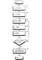
この場合の符号化及びその復号について、以下に説明する。図1は、本発明による符号化処理の手順を示すフローチャートである。図1において、最初に、データのビット長32ビットに対して、8ビットのチェックサムが付加される(ステップ10)。次に、この40ビットが、4ビットずつのビット列に分解される(ステップ20)。図2は、本発明による情報のビット列を示すビット構成図であり、ステップ10におけるビット列の構成、及びステップ20で4ビットずつ分解されて、10行10列のビットマップを構成する初期段階が示されている。 The encoding and decoding in this case will be described below. FIG. 1 is a flowchart showing a procedure of an encoding process according to the present invention. In FIG. 1, first, an 8-bit checksum is added to the data bit length of 32 bits (step 10). Next, the 40 bits are decomposed into 4-bit bit strings (step 20). FIG. 2 is a bit configuration diagram showing a bit sequence of information according to the present invention, showing the configuration of the bit sequence in
次に、これらの各4ビットデータは、1次元ウェーブレット変換であるHarr変換された空間に埋め込まれるため、Harr逆変換後の数値が2又0はとなるような低周波成分であるL成分と高周波成分であるH成分として配置される(ステップ30)。L成分は、データの情報成分であるビット列とチェックサムを含んでいる。H成分は、情報成分に難読性や不規則性を付加するための高周波成分、つまりノイズである。また、ビット列の先頭を検出するためのマーカ(M)が、L成分に1ビット(LM)、H成分に1ビット(HM)、各々配置される。 Next, since each of these 4-bit data is embedded in the space subjected to the Harr transform which is a one-dimensional wavelet transform, an L component which is a low frequency component such that the numerical value after the inverse Harr transform is 2 or 0 and It is arranged as an H component which is a high frequency component (step 30). The L component includes a bit string that is an information component of data and a checksum. The H component is a high frequency component for adding obfuscation and irregularity to the information component, that is, noise. Also, a marker (M) for detecting the head of the bit string is arranged with 1 bit (LM) for the L component and 1 bit (HM) for the H component.
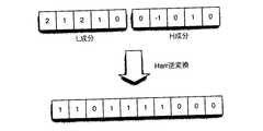
図3は、本発明のL成分及びH成分の構成を示すL、H成分構成図である。図3aにおいて、対応するデータのビットが1のとき、L成分が2、H成分が0となるよう事前に決められて配置されている。又、図3bにおいて、対応するデータのビットが0のときは、各L、H成分の組である(1、1)、(1、−1)のいずれかが、ランダムに設定されるように決められて配置されている。この場合、2ビット目の0には、(1、−1)が選択され、4ビット目の0には、(1、1)が選択されている。図3cにおいて、各ビットがこれらのプロセスを経た結果、データとマーカ(1、0、1、0、M)のL成分は、(2、1、2、1、LM)となり、H成分は、(0、−1、0、1、HM)となる。 FIG. 3 is an L, H component configuration diagram showing the configurations of the L component and the H component of the present invention. In FIG. 3a, when the corresponding data bit is 1, the L component is 2 and the H component is 0, and the data is determined and arranged in advance. In FIG. 3b, when the bit of the corresponding data is 0, either (1, 1) or (1, -1), which is a set of L and H components, is set at random. It is decided and arranged. In this case, (1, −1) is selected for 0 of the second bit, and (1, 1) is selected for 0 of the fourth bit. In FIG. 3c, as a result of each bit undergoing these processes, the L component of the data and the marker (1, 0, 1, 0, M) is (2, 1, 2, 1, LM), and the H component is (0, -1, 0, 1, HM).
次に、データの4ビットの行数が素数であれば、それぞれのマーカはLM=2、HM=0となり、素数でなければ、LM=0、HM=0となるよう事前に決められ、それぞれのマーカの数値が配置される(ステップ40)。図4は、L、H成分のマーカの配置を示すマーカ配置図である。1行目のデータ4ビットに対しては、1が素数ではないため、L成分のマーカLM、及び、H成分のマーカHMは共に0となっている。2行目のデータ4ビットに対しては素数行であるため、L成分のマーカLMは2となり、H成分のマーカHMは0となっている。このように10行まで素数行なら(2、0)、そうでなければ(0、0)が、各(LM、HM)に配置される。 Next, if the number of 4-bit rows of data is a prime number, the markers are determined in advance so that LM = 2 and HM = 0, and if not a prime number, LM = 0 and HM = 0. The numerical values of the markers are arranged (step 40). FIG. 4 is a marker arrangement diagram showing the arrangement of L and H component markers. Since 1 is not a prime number for the 4 bits of data in the first row, the L component marker LM and the H component marker HM are both 0. Since the data of 4 bits in the second row is a prime row, the L component marker LM is 2 and the H component marker HM is 0. In this way, if it is a prime number line up to 10 lines, (2, 0), otherwise (0, 0) is arranged in each (LM, HM).
このようにして作成された10行10列のビットマップがHarr変換された空間に埋め込まれた後、1行ずつHarr逆変換され、10行目までの逆変換が完了すると次のステップ移行する(ステップ50、ステップ60)。図5は、1行目のデータ4ビットがHarr逆変換された数値データ図である。図5において、原データ(1、0、1、0)とマーカがHarr変換された数値データ(2、1、2、1、0、0、−1、0、−1、0)がHarr逆変換され、数値データ(1、1、0、1、1、1、1、0、0、0)と成って示されている。 The 10-row 10-column bitmap created in this way is embedded in the space subjected to the Harr transformation, and then the Harr inverse transformation is performed for each row. When the inverse transformation up to the tenth row is completed, the next step is performed (
次にHarr逆変換されて得られた数値データを、2次元配列の2値画像データとして、媒体面の10×10ドットの格子上に埋め込む(ステップ70)。この10×10ドットの格子を1ブロックとして所定の情報のビットが埋め込まれ、さらにこのブロックが矩形状に配列されて情報の埋め込みが拡張される。図6は、1ブロックが媒体に印刷された状態を示す印刷パターンである。最初の1行目は、原データ(1、0、1、0)の2値画像データが、媒体面に印刷されたパターンを示している。2行目以下は、任意の原データの印刷パターンがイメージとして示されており、全体として10×10ドットの格子上に印刷された状態を示している。 Next, numerical data obtained by inverse Harr transformation is embedded as a two-dimensional array of binary image data on a 10 × 10 dot grid on the medium surface (step 70). Bits of predetermined information are embedded with this 10 × 10 dot grid as one block, and further, the information is embedded by arranging the blocks in a rectangular shape. FIG. 6 is a print pattern showing a state in which one block is printed on a medium. The first line shows a pattern in which binary image data of original data (1, 0, 1, 0) is printed on the medium surface. In the second and subsequent lines, a print pattern of arbitrary original data is shown as an image, and shows a state of being printed on a 10 × 10 dot grid as a whole.
図7は、本発明による復号処理の手順を示すフローチャートである。図7において、媒体面からブロック単位の面積で画像検出された印刷パターンは、回転処理やローテーションを行いながらHarr変換を繰り返し、マーカのパターンを検出する(ステップ110〜ステップ130)。マーカのパターンが検出されると、ノイズであるH成分のビットとマーカビット、及びL成分中のマーカビットは捨てられ、L成分の情報ビットのみが抽出される(ステップ140)。この抽出された情報ビットに対し、原データをHarr変換された空間に埋め込むため事前に決められていた変換ルールを適用し、ビット逆変換が行なわれ、原データが再現される(ステップ150)。 FIG. 7 is a flowchart showing the procedure of the decoding process according to the present invention. In FIG. 7, a print pattern in which an image is detected in an area of a block unit from the medium surface is repeatedly subjected to Harr conversion while performing rotation processing or rotation to detect a marker pattern (
図8は、復号処理のステップを示す復号処理図である。図8aは、原データ(1、0、1、0)の2値画像データの印刷パターンを示している。図8bは、画像検出された印刷パターンを画像処理し、量子化して、Harr逆変換された数値データ(1、1、0、1、1、1、1、0、0、0)を再現したビットパターンを示している。図8cは、マーカ検出によりブロックの位置が確定したときの、Harr変換された原データのビットパターン(2、1、2、1、0、0、−1、0、1、0)を示している。図8dは、原データをHarr変換された空間に埋め込むため、事前に決められていた変換ルールを適用し、ビット逆変換が行なわれ、再現された原データ(1、0、1、0)を示している。 FIG. 8 is a decoding process diagram showing steps of the decoding process. FIG. 8a shows a print pattern of binary image data of the original data (1, 0, 1, 0). FIG. 8b shows image processing of the detected print pattern, quantization, and reproduction of numerical data (1, 1, 0, 1, 1, 1, 1, 0, 0, 0) subjected to inverse Harr transformation A bit pattern is shown. FIG. 8 c shows the bit pattern (2, 1, 2, 1, 0, 0, −1, 0, 1, 0) of the original data subjected to the Harr conversion when the position of the block is determined by marker detection. Yes. In FIG. 8d, in order to embed the original data in the Harr-transformed space, a predetermined conversion rule is applied, bit inverse transformation is performed, and the reproduced original data (1, 0, 1, 0) is obtained. Show.
以上説明したように、本発明によると、Harr変換された空間に、データの位置と難読性や不規則性とを付加されたデータを配置し、且つ、Harr逆変換することにより得られた2値画像データを、ブロックを単位とする格子ドット上に埋め込むことが可能となる。このため、格子ドットの配置形状を大きくすることなくブロックを作成することが可能となり、作成されたブロックを媒体面に格子状に印刷することにより情報の拡張を図ることができる2次元バーコードの情報符号化方法を提供できる。 As described above, according to the present invention, the data obtained by arranging the data added with the data position and the obfuscation or irregularity in the Harr-transformed space and inversely transforming the Harr. It is possible to embed value image data on grid dots in units of blocks. For this reason, it is possible to create a block without increasing the arrangement shape of the grid dots, and a two-dimensional barcode that can expand information by printing the created block in a grid pattern on the medium surface. An information encoding method can be provided.
Claims (4)
Translated fromJapaneseHarr変換された空間に、埋め込まれるデータと、該データをマスクするためのノイズとを配置し、
前記データとノイズとが配置されたHarr変換された空間をHarr逆変換し、
得られた数値データを2値画像データとして前記ブロックの前記格子上に埋め込むことを特徴とするウェーブレット変換した2次元バーコードの情報符号化方法。An information encoding method of a wavelet-transformed two-dimensional barcode embedded in the grid dots on the medium surface on which the blocks formed by arranging the grid dots in a rectangular shape are continuously arranged,
Arranging embedded data and noise for masking the data in the space subjected to the Harr transform,
A Harr-transformed space in which the data and noise are arranged is inversely transformed into Harr;
A wavelet-transformed two-dimensional barcode information encoding method, wherein the obtained numerical data is embedded as binary image data on the lattice of the block.
Applications Claiming Priority (1)
| Application Number | Priority Date | Filing Date | Title |
|---|---|---|---|
| PCT/JP2008/050150WO2009087764A1 (en) | 2008-01-09 | 2008-01-09 | Information encoding method for two-dimensional bar code subjected to wavelet transformation |
Publications (1)
| Publication Number | Publication Date |
|---|---|
| JPWO2009087764A1true JPWO2009087764A1 (en) | 2011-05-26 |
Family
ID=40852889
Family Applications (1)
| Application Number | Title | Priority Date | Filing Date |
|---|---|---|---|
| JP2009548834APendingJPWO2009087764A1 (en) | 2008-01-09 | 2008-01-09 | Information encoding method of wavelet transformed 2D barcode |
Country Status (4)
| Country | Link |
|---|---|
| JP (1) | JPWO2009087764A1 (en) |
| KR (1) | KR20100105865A (en) |
| TW (1) | TW200941353A (en) |
| WO (1) | WO2009087764A1 (en) |
Families Citing this family (1)
| Publication number | Priority date | Publication date | Assignee | Title |
|---|---|---|---|---|
| GB201804818D0 (en)* | 2018-03-26 | 2018-05-09 | Data Signals Ltd | Method and apparatus for data obfuscation |
Citations (2)
| Publication number | Priority date | Publication date | Assignee | Title |
|---|---|---|---|---|
| JPH07123244A (en)* | 1993-09-03 | 1995-05-12 | Toshiba Corp | Image processing device |
| JP2006130801A (en)* | 2004-11-08 | 2006-05-25 | Seiko Instruments Inc | Printer, printing method and printing program |
- 2008
- 2008-01-09JPJP2009548834Apatent/JPWO2009087764A1/enactivePending
- 2008-01-09WOPCT/JP2008/050150patent/WO2009087764A1/enactiveApplication Filing
- 2008-01-09KRKR1020107016930Apatent/KR20100105865A/ennot_activeWithdrawn
- 2009
- 2009-01-07TWTW098100358Apatent/TW200941353A/enunknown
Patent Citations (2)
| Publication number | Priority date | Publication date | Assignee | Title |
|---|---|---|---|---|
| JPH07123244A (en)* | 1993-09-03 | 1995-05-12 | Toshiba Corp | Image processing device |
| JP2006130801A (en)* | 2004-11-08 | 2006-05-25 | Seiko Instruments Inc | Printer, printing method and printing program |
Also Published As
| Publication number | Publication date |
|---|---|
| TW200941353A (en) | 2009-10-01 |
| KR20100105865A (en) | 2010-09-30 |
| WO2009087764A1 (en) | 2009-07-16 |
Similar Documents
| Publication | Publication Date | Title |
|---|---|---|
| JP3628312B2 (en) | Watermark information embedding device and watermark information detection device | |
| US8014035B2 (en) | Decoding message data embedded in an image print via halftone dot orientation | |
| US8023160B2 (en) | Encoding message data in a cover contone image via halftone dot orientation | |
| WO2004098171A1 (en) | Watermark information detection method | |
| US6839450B2 (en) | Detecting halftone modulations embedded in an image | |
| US20030149879A1 (en) | Reversible watermarking | |
| JP2005514810A (en) | Generation of figure codes by halftoning using embedded figure coding | |
| US8270663B2 (en) | Watermarked information embedding apparatus | |
| US7523311B1 (en) | Method for embedding electronic watermark, decoding method, and devices for the same | |
| JP4400565B2 (en) | Watermark information embedding device and watermark information detection device | |
| JP4771283B2 (en) | Image processing apparatus, image forming apparatus, copy-forgery-inhibited pattern image, printed matter, image processing method, image forming method, and program | |
| JP2007501976A (en) | Background data channel on paper or other carrier | |
| EP3175423B1 (en) | Digital image watermarking system and method | |
| CN110766594A (en) | Information hiding method and device, detection method and device and anti-counterfeiting tracing method | |
| EP3047353B1 (en) | Data-bearing medium | |
| JP2005150815A (en) | Watermark information embedding apparatus and method, watermark information detecting apparatus and method, and printed matter | |
| EP2951675B1 (en) | Method of writing data to a data-bearing medium and method of recovering said data | |
| WO2009087764A1 (en) | Information encoding method for two-dimensional bar code subjected to wavelet transformation | |
| JPWO2004090801A1 (en) | Information encoding apparatus, information decoding apparatus, method and program thereof | |
| JP2006222788A (en) | Image verification device, image embedding device, image detection device, image embedding method, image detection method, computer program, and printed matter manufacturing method | |
| TWI411927B (en) | Method of embedding information in input image, method of extracting information from input image and related apparatuses thereof | |
| JP2008085579A (en) | Device for embedding information, information reader, method for embedding information, method for reading information and computer program | |
| US8270033B2 (en) | Generating embed-image by dividing embed-information into blocks and generating an information pattern and positioning pattern | |
| US7889884B2 (en) | Image processing apparatus and method | |
| JP4192906B2 (en) | Watermark information detection apparatus and watermark information detection method |
Legal Events
| Date | Code | Title | Description |
|---|---|---|---|
| A131 | Notification of reasons for refusal | Free format text:JAPANESE INTERMEDIATE CODE: A131 Effective date:20120731 | |
| A02 | Decision of refusal | Free format text:JAPANESE INTERMEDIATE CODE: A02 Effective date:20121127 |