JPWO2009081449A1 - Wavelength division multiplexing apparatus and optical signal dispersion compensation method - Google Patents
Wavelength division multiplexing apparatus and optical signal dispersion compensation methodDownload PDFInfo
- Publication number
- JPWO2009081449A1 JPWO2009081449A1JP2009546869AJP2009546869AJPWO2009081449A1JP WO2009081449 A1JPWO2009081449 A1JP WO2009081449A1JP 2009546869 AJP2009546869 AJP 2009546869AJP 2009546869 AJP2009546869 AJP 2009546869AJP WO2009081449 A1JPWO2009081449 A1JP WO2009081449A1
- Authority
- JP
- Japan
- Prior art keywords
- dispersion compensation
- line
- optical
- transponder
- optical transmission
- Prior art date
- Legal status (The legal status is an assumption and is not a legal conclusion. Google has not performed a legal analysis and makes no representation as to the accuracy of the status listed.)
- Pending
Links
Images


Classifications
- H—ELECTRICITY
- H04—ELECTRIC COMMUNICATION TECHNIQUE
- H04J—MULTIPLEX COMMUNICATION
- H04J14/00—Optical multiplex systems
- H04J14/02—Wavelength-division multiplex systems
- H04J14/0287—Protection in WDM systems
- H04J14/0289—Optical multiplex section protection
- H04J14/0291—Shared protection at the optical multiplex section (1:1, n:m)
- H—ELECTRICITY
- H04—ELECTRIC COMMUNICATION TECHNIQUE
- H04J—MULTIPLEX COMMUNICATION
- H04J14/00—Optical multiplex systems
- H04J14/02—Wavelength-division multiplex systems
- H04J14/0287—Protection in WDM systems
- H04J14/0289—Optical multiplex section protection
- H04J14/029—Dedicated protection at the optical multiplex section (1+1)
- H—ELECTRICITY
- H04—ELECTRIC COMMUNICATION TECHNIQUE
- H04J—MULTIPLEX COMMUNICATION
- H04J3/00—Time-division multiplex systems
- H04J3/02—Details
- H04J3/14—Monitoring arrangements
Landscapes
- Engineering & Computer Science (AREA)
- Computer Networks & Wireless Communication (AREA)
- Signal Processing (AREA)
- Optical Communication System (AREA)
Abstract
Translated fromJapaneseDescription
Translated fromJapanese本発明は、波長分割多重装置及び光信号の分散補償方法に関する。 The present invention relates to a wavelength division multiplexing apparatus and an optical signal dispersion compensation method.
近年、大容量化、小型、低コスト、周波数利用効率の高さなどの利点のために、次世代の40Gbit/s光伝送システムの導入の要求が高まっている。
一般に、光ファイバや各ノードに配置される装置を構成する各種光部品は波長分散をもっているため、変調された信号光がこれらを通過する際に波長分散のために光波形のひずみが生じる。光波形のひずみは伝送品質(誤り率など)の劣化を引き起こすため、最大伝送距離などのシステム性能を制限する要因となっている。In recent years, due to advantages such as large capacity, small size, low cost, and high frequency utilization efficiency, there is an increasing demand for introduction of a next-generation 40 Gbit / s optical transmission system.
In general, since various optical components constituting an optical fiber and a device arranged at each node have chromatic dispersion, distortion of the optical waveform occurs due to chromatic dispersion when modulated signal light passes through them. The distortion of the optical waveform causes deterioration in transmission quality (error rate, etc.), and is a factor that limits system performance such as maximum transmission distance.
一般に、送受信器の分散による波形ひずみに対する耐力を表す指標として分散トレランスが用いられている。例えば、40Gbit/s以上のビットレートにおける送受信機の分散トレランスは数10ps/nm程度である。これは現在広く実用されている10Gbit/s信号が1000ps/nm程度の分散トレランスをもつことに比較して非常に小さい。このため、40Gbit/s以上のビットレートの信号の伝送を実現するためには、受信機入力端に可変分散補償器(VDC:Variable Dispersion Compensator)を配置するなどして高精度な分散制御を行う必要がある。 Generally, dispersion tolerance is used as an index representing the tolerance to waveform distortion due to dispersion of a transceiver. For example, the dispersion tolerance of a transceiver at a bit rate of 40 Gbit / s or more is about several tens of ps / nm. This is very small as compared with the 10 Gbit / s signal that is currently widely used and having a dispersion tolerance of about 1000 ps / nm. For this reason, in order to realize transmission of a signal with a bit rate of 40 Gbit / s or more, highly accurate dispersion control is performed by arranging a variable dispersion compensator (VDC) at the receiver input end. There is a need.
一方、現在ではネットワークの高信頼性確保のため、光ファイバが切断された場合など障害発生時の高速なサービス復旧(通常50ms以下)が求められている。
このような目的のため、OUPSR(Optical Unidirectional Path Switched Ring)を代表とするプロテクション方式が導入されてきている。On the other hand, at present, in order to ensure high reliability of a network, high-speed service recovery (usually 50 ms or less) is required when a failure occurs such as when an optical fiber is cut.
For this purpose, a protection method represented by OUPSR (Optical Unidirectional Path Switched Ring) has been introduced.
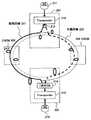
図20は、OUPSR方式の光ネットワークの構成の一例を示す図である。この光ネットワークは、波長分割多重装置201と、OADM(Optical Add Drop Multiplexer)202と、波長分割多重装置203と、OADM204が、リング状に接続されている。 FIG. 20 is a diagram illustrating an example of the configuration of an OUPSR optical network. In this optical network, a
ルータ211から入力した信号は、トランスポンダ212、光スプリッタ213を経て現用回線221に出力され、OADM202を経由して受信側の波長分割多重装置203に入力する。波長分割多重装置203は、1波光スイッチ214とトランスポンダ215を有し、トランスポンダ215で分散補償した光信号をルータ216に出力する。トランスポンダ212は、他のOADM204を経由する予備回線222を有している。 A signal input from the
この光ネットワークシステムにおいて、現用回線221に障害が発生すると、受信側のトランスポンダ215は、予備回線222に切り替えて信号を受信する。
例えば、40Gbit/sの通信では分散トレランスが小さいため、受信側のトランスポンダ215は、可変分散補償器(Variable Dispersion Compensator)の分散補償量を最適値に設定するための調整を行う必要があり、現状では障害発生から信号疎通までに数分間の時間を要している。In this optical network system, when a failure occurs in the work line 221, the
For example, since the dispersion tolerance is small in communication of 40 Gbit / s, it is necessary for the
特許文献1には、複数の光伝送ルートの最適分散補償量を予めメモリに記憶しておき、ルート変更検出手段により光り伝送ルートの変更が検出されると、メモリに記憶されている変更後のルートの最適分散補償量に応じて可変分散補償器の分散補償量を制御することが記載されている。
本発明の課題は、光ネットワークにおける回線障害の復旧時間を短縮することである。
波長分割多重装置の1つの態様は、送信側の光伝送装置と受信側の光伝送装置が、現用回線と予備回線により接続されているネットワークに用いられる波長分割多重装置であって、前記予備回線と同じ光回線に収容されている現用回線に対する分散補償情報を、他の光伝送装置から取得する取得手段と、前記取得手段で取得した分散補償情報に基づいて前記予備回線を伝送される光信号の分散を補償する分散補償手段とを備える。An object of the present invention is to shorten the recovery time of a line failure in an optical network.
One aspect of the wavelength division multiplexing apparatus is a wavelength division multiplexing apparatus used in a network in which a transmission side optical transmission apparatus and a reception side optical transmission apparatus are connected by a working line and a protection line, the protection line Acquisition means for acquiring dispersion compensation information for the working line accommodated in the same optical line from another optical transmission device, and an optical signal transmitted through the protection line based on the dispersion compensation information acquired by the acquisition means Dispersion compensation means for compensating for the dispersion of.
この波長分割多重装置によれば回線障害の復旧時間を短縮できる。
上記の波長分割多重装置において、前記取得手段は、障害が検出される前に、前記他の光伝送装置の記憶手段に記憶されている分散補償情報を取得する。According to this wavelength division multiplexing apparatus, the recovery time of a line failure can be shortened.
In the wavelength division multiplexing apparatus, the acquisition unit acquires the dispersion compensation information stored in the storage unit of the other optical transmission device before a failure is detected.
このように構成することで、障害が発生する前に他の光伝送装置の現用回線に対する分散補償情報を取得しておくことができるので、障害の復旧時間をさらに短縮できる。
上記の波長分割多重装置において、前記取得手段は、他の光伝送装置からネットワーク上に送出される分散補償情報を受信し、前記分散補償手段は、前記取得手段で受信した前記分散補償情報に基づいて前記予備回線に対する分散補償を行う。With this configuration, it is possible to acquire dispersion compensation information for the working line of another optical transmission apparatus before a failure occurs, so that the failure recovery time can be further shortened.
In the wavelength division multiplexing apparatus, the acquisition unit receives dispersion compensation information transmitted from another optical transmission device to the network, and the dispersion compensation unit is based on the dispersion compensation information received by the acquisition unit. Dispersion compensation for the protection line.
このように構成することで、ネットワーク上に送信される他の光伝送装置の分散補償情報を受信して予備回線の分散補償を行うことができる。
上記の波長分割多重装置において、前記取得手段は、前記他の光伝送装置が受信している光信号の波長と自装置が受信する光信号の波長の差に応じて、前記他の光伝送装置から受信する前記分散補償情報を補正し、補正した値を前記予備回線に対する分散補償情報として算出する。With this configuration, it is possible to receive dispersion compensation information of another optical transmission apparatus transmitted over the network and perform dispersion compensation for the protection line.
In the above-described wavelength division multiplexing apparatus, the acquisition unit may select the other optical transmission apparatus according to a difference between the wavelength of the optical signal received by the other optical transmission apparatus and the wavelength of the optical signal received by the own apparatus. The dispersion compensation information received from is corrected, and the corrected value is calculated as dispersion compensation information for the protection line.
このように構成することで、異なる波長の光信号に対する分散補償情報から、波長に応じた適切な分散補償情報を得ることができる。
上記の波長分割多重装置において、前記分散補償手段の分散補償情報をOSC(Optical Supervisor Channel)を用いてネットワーク上の他の光伝送装置に送信する出力手段を有する。With this configuration, appropriate dispersion compensation information corresponding to the wavelength can be obtained from the dispersion compensation information for optical signals having different wavelengths.
The wavelength division multiplexing apparatus includes output means for transmitting dispersion compensation information of the dispersion compensation means to another optical transmission apparatus on the network using an OSC (Optical Supervisor Channel).
このように構成することで、OSCを利用して自装置の分散補償情報を他の光伝送装置に送信することができる。
上記の波長分割多重装置において、前記分散補償手段の分散補償情報を、主信号の信号フォーマットのオーバヘッドの空きバイトに挿入してネットワーク上の他の光伝送装置に送信する出力手段を有する。With this configuration, the dispersion compensation information of the own apparatus can be transmitted to another optical transmission apparatus using OSC.
The wavelength division multiplexing apparatus includes an output unit that inserts the dispersion compensation information of the dispersion compensation unit into an empty byte of the overhead of the signal format of the main signal and transmits it to another optical transmission device on the network.
このように構成することで、主信号の信号フォーマットを利用して自装置の分散補償情報を送信することができる。
上記の波長分割多重装置において、前記分散補償手段における分散補償情報を記憶すると共に、記憶した分散補償情報を他の光伝送装置に出力する記憶手段を有し、前記取得手段は、他の光伝送装置の記憶手段から自装置の予備回線と同じ光回線に収容されている現用回線に対する分散補償情報を取得する。With this configuration, it is possible to transmit the dispersion compensation information of the own device using the signal format of the main signal.
In the wavelength division multiplexing apparatus, the dispersion compensation information in the dispersion compensation unit is stored, and the storage unit outputs the stored dispersion compensation information to another optical transmission device, and the acquisition unit includes other optical transmission The dispersion compensation information for the working line accommodated in the same optical line as the protection line of the own apparatus is acquired from the storage means of the apparatus.
このように構成することで、他の光伝送装置の記憶手段から現用回線に対する分散補償情報を取得して自装置の分散補償情報を設定することができる。
上記の波長分割多重装置において、前記取得手段は、前記分散補償手段の分散補償値を設定すると共に、設定した分散補償値を他の光伝送装置に出力する設定手段を有し、前記設定手段は、他の光伝送装置の設定手段から自装置の予備回線と同じ光回線に収容されている現用回線に対する分散補償値を取得し、取得した前記分散補償値を前記分散補償手段に設定する。With this configuration, it is possible to obtain dispersion compensation information for the working line from the storage unit of another optical transmission apparatus and set the dispersion compensation information of the own apparatus.
In the wavelength division multiplexing apparatus, the acquisition unit includes a setting unit that sets a dispersion compensation value of the dispersion compensation unit and outputs the set dispersion compensation value to another optical transmission device. Then, the dispersion compensation value for the working line accommodated in the same optical line as the protection line of the own apparatus is obtained from the setting means of the other optical transmission apparatus, and the obtained dispersion compensation value is set in the dispersion compensation means.
このように構成することで、他の光伝送装置の設定手段から現用回線に対する分散補償値を取得し、その取得した値に基づいて短時間で自装置の分散補償手段に適正な分散補償値を設定することができる。 By configuring in this way, the dispersion compensation value for the working line is obtained from the setting means of the other optical transmission apparatus, and an appropriate dispersion compensation value is obtained in the dispersion compensation means of the own apparatus in a short time based on the obtained value. Can be set.
上記の波長分割多重装置において、受信する主信号の信号品質を検出する信号品質検出手段と、前記信号品質検出手段で検出される信号品質に基づいて修正した分散補償情報を算出する算出手段と、前記算出手段で算出された分散補償情報を記憶すると共に、記憶した分散補償情報を他の光伝送装置に出力する記憶手段を有し、前記取得手段は、他の光伝送装置の記憶手段から自装置の予備回線と同じ光回線に収容されている現用回線に対する分散補償情報を取得し、取得した前記分散補償情報に基づいて前記分散補償手段の分散補償値を設定する設定手段を有する。 In the above wavelength division multiplexing apparatus, signal quality detection means for detecting the signal quality of the received main signal, calculation means for calculating dispersion compensation information corrected based on the signal quality detected by the signal quality detection means, In addition to storing the dispersion compensation information calculated by the calculating means, the storage means outputs the stored dispersion compensation information to another optical transmission apparatus, and the acquisition means is automatically stored in the storage means of the other optical transmission apparatus. It has setting means for obtaining dispersion compensation information for the working line accommodated in the same optical line as the protection line of the apparatus and setting a dispersion compensation value of the dispersion compensation means based on the obtained dispersion compensation information.
このように構成することで、設定手段が、他の光伝送装置の記憶手段から現用回線に対する分散補償情報を取得し、その取得した値に基づいて短時間で自装置の分散補償手段に適切な分散補償値を設定することができる。 With this configuration, the setting unit acquires the dispersion compensation information for the working line from the storage unit of the other optical transmission apparatus, and is suitable for the dispersion compensation unit of the own apparatus in a short time based on the acquired value. A dispersion compensation value can be set.
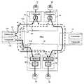
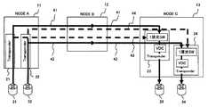
以下、本発明の好適な実施の形態を図面を参照して説明する。図1は、第1の実施の形態の光ネットワークの構成を示す図である。この光ネットワークは、40Gbit/sの通信速度で信号を伝送する例である。 Preferred embodiments of the present invention will be described below with reference to the drawings. FIG. 1 is a diagram illustrating a configuration of an optical network according to the first embodiment. This optical network is an example of transmitting a signal at a communication speed of 40 Gbit / s.
図1は、4台のノードがリング状に接続されたOADM(Optical Add Drop Multiplex) RINGのネットワーク構成を示している。
以下、説明を簡単にするために、波長分割多重装置(WDM:Wavelength Division multiplex)が2台のトランスポンダを有する場合について説明する。波長分割多重装置(NODE A)11は、トランスポンダ(光伝送装置に対応する)21,22を有する。波長分割多重装置13も2台のトランスポンダ23、24を有する。FIG. 1 shows a network configuration of an OADM (Optical Add Drop Multiplex) RING in which four nodes are connected in a ring shape.
Hereinafter, in order to simplify the description, a case where a wavelength division multiplex apparatus (WDM) has two transponders will be described. The wavelength division multiplexing apparatus (NODE A) 11 includes transponders (corresponding to optical transmission apparatuses) 21 and 22. The wavelength
図1のネットワークは、トランスポンダ21及び22から出力された光信号が、それぞれ現用回線41と予備回線44に出力され、伝送路上にある波長分割多重装置12をスルーで通過してトランスポンダ23及び24で受信され、トランスポンダ21及び22から出力された光信号が、それぞれ予備回線43と現用回線42に出力され、波長分割多重装置14をスルーで通過してトランスポンダ23及び24で受信される場合の例である。 In the network of FIG. 1, the optical signals output from the
トランスポンダ21、22は、それぞれルータ31、32から入力する信号をWDM用の波長の光信号に変換する。トランスポンダ21から出力された光信号は、光スプリッタ21aによって現用回線41と予備回線43の2方向に分岐される。また、トランスポンダ22から出力された光信号は、光スプリッタ22aによって現用回線42と予備回線44の2方向に分岐される。 The
トランスポンダ21は、波長分割多重装置(NODE B)12をスルーで通過して波長分割多重装置(NODE C)13のトランスポンダ23に至る経路を現用回線41として使用している。その現用回線41が収容されている物理回線にトランスポンダ22の予備回線44が収容されている(図1に破線で示す予備回線44)。 The
トランスポンダ22は、波長分割多重装置(NODE D)14をスルーで通過して波長分割多重装置13に至る経路を現用回線42として使用している。その現用回線42が収容されている物理回線にトランスポンダ21の予備回線43が収容されている。 The
波長分割多重装置13のトランスポンダ23、24は、現用または予備回線の一方を選択して光信号を出力する1波光スイッチ(以下、光スイッチと呼ぶ)51、52と、残留分散を補償するための可変分散補償器(VDC:Variable Dispersion Compensator)53、54を有する。可変分散補償器53、54は、例えば、他のトランスポンダの分散補償情報(VDC設定値など)を取得する機能と、残留分散を補償する機能(取得手段、分散補償手段に対応する)を有する。 The
トランスポンダ23は、光スイッチ51により現用回線41と予備回線43の一方を選択し、可変分散補償器53により光信号の分散を補償して、トランスポンダ23内にて光―電気変換したのち、誤り訂正などを含む信号処理を行った後、再び、電気―光変換してルータ33に出力する。同様に、トランスポンダ24は、光スイッチ52により現用回線42と予備回線44の一方を選択し、可変分散補償器54により分散を補償した光信号を、同様に信号処理した後、ルータ34に出力する。 The
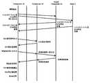
図2は、現用回線41に障害が発生して予備回線43に切り替える場合の第1の実施の形態の動作シーケンスを示す図である。
トランスポンダ23の可変分散補償器53は、通常は、現用回線41の分散補償量を動的に最適値に設定している。FIG. 2 is a diagram illustrating an operation sequence according to the first embodiment in the case where a failure occurs in the working
In general, the
トランスポンダ23は、光信号断、フレーム同期はずれ、誤り率の劣化などにより現用回線41の回線障害と判断すると、トランスポンダ24に現用回線42に対するVDC設定値(分散補償情報に対応する)を問い合わせる。 When the
トランスポンダ24は、VDC設定値の問い合わせを受け付けると、自己の可変分散補償器54のVDC設定値を取得し、そのVDC設定値をトランスポンダ23に送信する。
トランスポンダ23は、受信したVDC設定値を自己の可変分散補償器53に出力し、可変分散補償器53は、受信したVDC設定値を予備回線43のVDC設定値(分散補償量)として設定する。VDC設定値の変更が終了したなら、光スイッチ51は、使用する回線を現用回線41から予備回線43に切り替える。When receiving the inquiry about the VDC setting value, the
The
上記のようにトランスポンダ24の現用回線42と同じ光回線に収容されている予備回線43に対するVDC設定値を、現用回線42のVDC設定値に基づいて設定することで予備回線43に対するVDC設定値の設定時間を短縮できる。 As described above, by setting the VDC setting value for the
なお、上記の例では、可変分散補償回路53へのVDC設定値の設定が終了してから回線を切り替えているが、光スイッチ51により予備回線に切り替えた後、VDC設定値の変更を行っても良い。また、予備回線43が収容されている光回線の一部を現用回線として使用しているトランスポンダ24のVDC設定値を予め取得し、そのVDC設定値をメモリに記憶しておいても良い。 In the above example, the line is switched after the setting of the VDC setting value to the tunable
上述した第1の実施の形態によれば、回線障害が発生して予備回線に切り替える場合に、信号が疎通するまでの時間を短縮できる。
一般に、光ファイバや各ノードに配置される分散補償器は波長特性を有している。図1のトランスポンダ21から出力される光信号の波長と、トランスポンダ22から出力される光信号の波長が異なる場合には、受信側のトランスポンダ23及び24における残留分散量も異なる値となる。According to the first embodiment described above, when a line failure occurs and the line is switched to a protection line, it is possible to shorten the time until the signal communicates.
In general, an optical fiber and a dispersion compensator arranged at each node have wavelength characteristics. When the wavelength of the optical signal output from the
トランスポンダ24の現用回線42に対するVDC設定値は、現用回線42を伝送される光信号の波長における残留分散に対して設定されている。そのためトランスポンダ23の予備回線43に対するVDC設定値を、現用回線42のVDC設定値と等しく設定すると、両者の光信号の波長が異なるためにVDC設定値が最適値とならない可能性がある。 The VDC setting value for the
図3は、上記の問題を解決するための第2の実施の形態の動作シーケンスを示す図である。この第2の実施の形態は、信号の波長の違いを考慮してVDC設定値を修正するものである。 FIG. 3 is a diagram showing an operation sequence of the second embodiment for solving the above problem. In the second embodiment, the VDC setting value is corrected in consideration of the difference in signal wavelength.
トランスポンダ23は、現用回線41の障害を検出すると、送信側のトランスポンダ22とノードD(波長分割多重装置14)に対してファイバタイプ/ファイバ長、DCM用品を問い合わせる。DCM用品を特定することで可変分散補償器の波長特性に関するデータを得ることができる。 When the
問い合わせを受けたトランスポンダ22とノードDは、それぞれファイバタイプ/ファイバ長、DCM(Dispersion Compensator Mpdule)用品に関する情報を送信する。
次に、トランスポンダ23は、トランスポンダ24にVDC設定値を問い合わせる。問い合わせを受けたトランスポンダ24は、自己の可変分散補償器54のVDC設定値をトランスポンダ23に送信する。Upon receiving the inquiry, the
Next, the
次に、トランスポンダ23は、トランスポンダ24に受信波長を問い合わせる。また、トランスポンダ24は、送信側のトランスポンダ22に送信波長を問い合わせる。問い合わせを受けた、送信側のトランスポンダ22は、送信波長データを受信側のトランスポンダ24に送信する。受信側のトランスポンダ24は、送信側のトランスポンダ24から受信した波長データを受信波長データとしてトランスポンダ23に送信する。 Next, the
受信側のトランスポンダ23の可変分散補償器53は、トランスポンダ24から受信したVDC設定値と受信波長データに基づいてVDC設定値を波長に合わせて修正する。そして、光スイッチ53が現用回線41から予備回線43に切り替えた後、さらにVDC設定値の調整を行う。 The
ここで、ファイバタイプ/ファイバ長、伝送経路上のノードの可変分散補償器の波長特性に基づいて残留分散を補正する方法について説明する。
送信側のトランスポンダ21の出力光の波長をλ1、トランスポンダ22の出力光の波長をλ2とし、波長λに対するトランスポンダの入力端における残留分散をRDとすると、VDC設定値の補正は、以下の式で行うことができる。Here, a method for correcting the residual dispersion based on the fiber type / fiber length and the wavelength characteristics of the variable dispersion compensator of the node on the transmission path will be described.
When the wavelength of the output light from the
VDC(λ1)=VDC(λ2)+[RD(λ2)−RD(λ1)] (1)
残留分散RD(λ)は、波長λに対するトランスポンダ入力端における残留分散を示し、伝送路ファイバ分散Dfiberと、分散補償器(分散補償ファイバ)の分散Ddcmから以下の式により求めることができる。VDC (λ1) = VDC (λ2) + [RD (λ2) −RD (λ1)] (1)
The residual dispersion RD (λ) indicates the residual dispersion at the transponder input end with respect to the wavelength λ, and can be obtained from the transmission line fiber dispersion Dfiber and the dispersion Ddcm of the dispersion compensator (dispersion compensation fiber) by the following equation.
RD(λ)=[Dfiber1(λ)+Dfiber2(λ)・・・+Dfibern]
+[Ddcm1(λ)+Ddcm2(λ)・・・・+Ddcmn(λ)] (2)
DfiberとDdcmは、波長λに対して次式から計算できる。RD (λ) = [Dfiber1 (λ) + Dfiber2 (λ)... + Dfibern]
+ [Ddcm1 (λ) + Ddcm2 (λ)... + Ddcmn (λ)] (2)
Dfiber and Ddcm can be calculated from the following equation with respect to the wavelength λ.
Dfibern(λ)=[a0+a1×(λ−λref)]×FiberLengthn
Ddcmn(λ)=[b0+b1×(λ−λref)]×DcfLengthn
a0、a1は、それぞれ伝送路ファイバの分散係数(ps/nm/km)と分散スロープ(2次分散)係数(ps/nm2/km)を表す。Dfibern (λ) = [a0 + a1 × (λ−λref)] × FiberLengthn
Ddcmn (λ) = [b0 + b1 × (λ−λref)] × DcfLengthn
a0 and a1 represent the dispersion coefficient (ps / nm / km) and dispersion slope (secondary dispersion) coefficient (ps / nm2 / km) of the transmission line fiber, respectively.
b0、b1は、それぞれ分散補償器(分散補償ファイバ)の分散係数(ps/nm/km)と分散スロープ(2次分散)係数(ps/nm2/km)を表す。λrefは、分散係数を規定する規定波長(例えば、1550nm)を表す。 b0 and b1 respectively represent the dispersion coefficient (ps / nm / km) and dispersion slope (secondary dispersion) coefficient (ps / nm2 / km) of the dispersion compensator (dispersion compensation fiber). λref represents a specified wavelength (for example, 1550 nm) that defines the dispersion coefficient.
上記の式から波長λ1の光信号に対する予備回線のVDC設定値を求めることができる。
次に、図4は、第3の実施の形態のネットワーク構成を示す図である。この第3の実施の形態は、異なる波長の信号が伝送される複数の現用回線に対するVDC設定値から、同じ回線内にある他の波長の信号が伝送される予備回線のVDC設定値を求めるものである。以下、図1と同じ要素には同じ符号を付けてそれらの説明は省略する。From the above equation, the VDC setting value of the protection line for the optical signal of wavelength λ1 can be obtained.
Next, FIG. 4 is a diagram illustrating a network configuration according to the third embodiment. In the third embodiment, a VDC setting value of a protection line for transmitting signals of other wavelengths in the same line is obtained from VDC setting values for a plurality of working lines for transmitting signals of different wavelengths. It is. In the following, the same elements as those in FIG.
図4に示す波長分割多重装置15は、3台のトランスポンダ21、22、25を有する。トランスポンダ21、22、25は、ルータ31、32、35から出力される信号を、それぞれVDM用の所定の波長λ1、λ2、λ3の信号に変換する。これらの光信号は、光スプリッタ21a、22a、25aでそれぞれ2方向に分岐される。光スプリッタ21aで分岐された波長λ1の信号は現用回線41と予備回線43に送出され、光スプリッタ22aで分岐された波長λ2の信号は現用回線42と予備回線44に送出され、光スプリッタ25aで分岐された波長λ3の信号は現用回線45と予備回線46に送出される。 The wavelength
受信側の波長分割多重装置16は、3台のトランスポンダ23、24、26を有する。トランスポンダ26は、現用回線45と予備回線46の一方を選択する光スイッチ55と、光信号の分散を補償する可変分散補償器(VDC)56を有し、分散を補償した信号をルータ36に出力する。 The wavelength
トランスポンダ24の可変分散補償器54における波長λ2の信号に対するVDC設定値をVDC(λ2)、トランスポンダ26の可変分散補償器56における波長λ3の信号に対するVDC設定値をVDC(λ3)とすると、波長λ1に対するVDC設定値VDC(λ1)は、以下の式から求めることができる。 When the VDC setting value for the signal of wavelength λ2 in the
VDC(λ1)=VDC(λ2)+{VDC(λ2)−VDC(λ3)}×(λ1−λ2)/(λ2−λ3)
波長λ2の光信号が伝送される現用回線42に対するVDC設定値VDC(λ2)と、波長λ3の光信号が伝送される現用回線45に対するVDC設定値VDC(λ3)の差分と、波長λ2と波長λ3の差分の比を算出し、その値に波長λ1と波長λ2の差分を乗算することで、波長λ1の光信号が伝送される予備回線43に対するVDC設定値を算出することができる。VDC (λ1) = VDC (λ2) + {VDC (λ2) −VDC (λ3)} × (λ1-λ2) / (λ2-λ3)
The difference between the VDC setting value VDC (λ2) for the working
上述した第3の実施の形態によれば、波長の異なる信号が伝送される伝送路に対するVDC設定値を取得し、取得したそれらのVDC設定値から、波長の異なる光信号が伝送される予備回線に対する好適なVDC設定値を算出することができる。これにより、光信号の波長の違いによるVDC設定値の誤差を少なくし、より短時間でVDC設定値の調整を終了することができる。 According to the third embodiment described above, the VDC setting values for the transmission lines on which signals having different wavelengths are transmitted are acquired, and the protection lines on which optical signals having different wavelengths are transmitted from the acquired VDC setting values. A suitable VDC set value for can be calculated. Thereby, the error of the VDC setting value due to the difference in the wavelength of the optical signal can be reduced, and the adjustment of the VDC setting value can be completed in a shorter time.
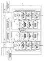
次に、図5は、第4の実施の形態の波長分割多重装置13の構成を示す図である。図5の予備回線43は、現用回線42と同じ光回線に収容されており、予備回線44は、現用回線41と同じ光回線に収容されている。以下の説明では、図1と同じ要素には同じ符号を付けてそれらの説明を省略する。 Next, FIG. 5 is a diagram illustrating a configuration of the wavelength
この第4の実施の形態は、トランスポンダ23のVDC設定回路61が、他のトランスポンダ24のVDC設定回路71からVDC設定値(分散補償情報)を取得し、そのVDC設定値に基づいて予備回線44のVDC設定値を決めるものである。 In the fourth embodiment, the
VDC設定回路61は、トランスポンダ24のVDC設定回路71のVDC設定値を取得し、取得した値を自装置の可変分散補償回路63のVDC設定値として設定する。
1波長光スイッチ62(図1の光スイッチ51に該当する)は、現用回線(Work Path)41と予備回線(Protection Path)44の一方を選択して可変分散補償回路(VDC)63に出力する。可変分散補償回路63(図1のVDC53に該当する)は、VDC設定回路61から出力されるVDC設定値に基づいて光信号の分散を補償する。The
The one-wavelength optical switch 62 (corresponding to the
光・電気変換回路64は、光信号を電気信号に変換し、エラー/障害検出回路65は、光信号の断、誤り率の劣化等から光信号のエラーや回線の障害を検出する。
信号処理部66は、受信した信号のフレームフォーマットをクライアント側の信号のフレームフォーマットに変換する。電気・光変換回路67は、電気信号を光信号に変換して出力する。The optical /
The
光スイッチ状態管理部68は、1波長光スイッチ62の状態を監視する回路であり、1波長光スイッチ62が現用回線41と予備回線44の何れを選択しているかを示す情報を出力する。 The optical switch
VDC設定値算出回路69は、伝送路の物理的条件により定まる残留分散値からVDC設定値を算出すると共に、エラー/障害検出回路65から出力される信号品質を示すデータに基づいて主信号の品質が最良となるVDC設定値に調整し、調整した値をVDC設定回路61に出力する。 The VDC set
トランスポンダ24は、VDC設定回路71、1波長光スイッチ72、可変分散補償回路73、光・電気変換回路74、エラー/障害検出回路75、信号処理部76、光スイッチ状態管理部78、VDC設定値算出回路79を有する。これらの回路の機能は、トランスポンダ23の各回路と同じである。 The
トランスポンダ23のエラー/障害検出回路65において現用回線41の障害が検出されると、VDC設定回路61は、トランスポンダ24のVDC設定回路71から現用回線42に対するVDC設定値を取得し、取得したVDC設定値を可変分散補償回路63に出力する。可変分散補償回路63は、そのVDC設定値に基づいて主信号の分散補償を行う。その後、VDC設定値算出回路69が、エラー/障害検出回路65で検出される信号の品質を示すデータ、例えば、主信号のフレーム同期はずれの頻度、誤り率等を示すデータを参照して同期はずれの頻度、誤り率が最小となるようにVDC設定値を微調整し、微調整した値をVDC設定回路61に出力する。VDC設定回路61は修正されたVDC設定値を可変分散補償回路63に出力して分散補償を行わせる。このような動作を繰り返すことで予備回線44に対する最適な分散補償値を決めることができる。 When the error /
第4の実施の形態によれば、例えば、現用回線41に障害が発生した場合に、他のトランスポンダ24のVDC設定回路71から現用回線42に対するVDC設定値を取得し、取得したVDC設定値に基づいて現用回線42と同じ物理回線に収容されている予備回線44のVDC設定値を設定することができる。従って、短時間で最適なVDC設定値を得ることができるので、回線障害が検出されて予備回線に切り替える場合の障害の復旧時間を短縮できる。 According to the fourth embodiment, for example, when a failure occurs in the working
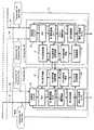
次に、図6は、第5の実施の形態の波長分割多重装置13の構成を示す図である。この第5の実施の形態は、他のトランスポンダ24のVDC設定値記憶回路82に記憶されているVDC設定値をVDC設定回路61が取得し、取得した値に基づいて予備回線44のVDC設定値を設定するものである。 Next, FIG. 6 is a diagram illustrating a configuration of the wavelength
図6のトランスポンダ23の予備回線44は、トランスポンダ24の現用回線42と同じ物理回線(光回線)に収容されている。以下、図5と同じ回路ブロックには同じ符号を付けてそれらの説明は省略する。 The
図6において、トランスポンダ23のVDC設定値記憶回路81は、VDC設定値算出回路69で算出されたVDC設定値を記憶する。このVDC設定値記憶回路81に記憶されたVDC設定値は、自装置のVDC設定回路61に出力されると共に、他のトランスポンダ24のVDC設定回路71に出力される。 In FIG. 6, the VDC setting
トランスポンダ24も同様に、VDC設定値算出回路79で算出されたVDC設定値を記憶するVDC設定値記憶回路82を有する。このVDC設定値記憶回路82に記憶されたVDC設定値は、自装置のVDC設定回路71と、他のトランスポンダ23のVDC設定回路61に出力されている。 Similarly, the
トランスポンダ23のVDC設定回路61は、回線が正常なときは、自装置のVDC設定値記憶回路81に記憶されているVDC設定値を取得し、取得したVDC設定値を可変分散補償回路63に出力する。 When the line is normal, the
他方、エラー/障害検出回路65において現用回線41の障害が検出されたとき、あるいは障害が検出される前に、VDC設定回路61は、他のトランスポンダ24のVDC設定値記憶回路82に記憶されているVDC設定値を取得し、その取得したVDC設定値を可変分散補償回路63に出力する。 On the other hand, the
回線障害が検出されると、1波長光スイッチ62は、回線を予備回線44に切り替える。VDC設定値算出回路69は、エラー/障害検出回路65で検出される主信号の誤り率等が改善されるようにVDC設定値を調整し、調整後のVDC設定値をVDC設定値記憶回路81に出力する。VDC設定回路61は、VDC設定値記憶回路81に新たに書き込まれたVDC設定値を可変分散補償回路63に出力する。可変分散補償回路63は、そのVDC設定値に基づいて主信号の分散補償を行う。分散補償を行った後の主信号は、エラー/障害検出回路65において、主信号の誤り率等が算出され、その結果に基づいてさらにVDC設定値の調整が行われる。 When a line failure is detected, the one-wavelength
上記の第5の実施の形態によれば、トランスポンダ23は、他のトランスポンダ24のVDC設定値記憶回路82から、予備回線44と同じ物理回線に収容されている現用回線42に対するVDC設定値を予め(または障害発生時に)取得することができる。従って、回線障害が検出されたときに、予備回線44における光信号の分散を補償するための最適なVDC設定値を迅速に可変分散補償回路63に出力することができる。これにより、回線障害の復旧時間を短縮できる。 According to the fifth embodiment described above, the
次に、図7は、第6の実施の形態の波長分割多重装置13の構成を示す図である。この第6の実施の形態は、VDC設定値記憶回路81が、他のトランスポンダ24のVDC設定値記憶回路82のVDC設定値を取得し、取得したVDC設定値をVDC設定回路61に出力するものである。 Next, FIG. 7 is a diagram illustrating a configuration of the wavelength
図7のトランスポンダ23の予備回線43は、トランスポンダ24の現用回線42と同じ物理回線に収容されている。以下、図5と同じ回路ブロックには同じ符号を付けてそれらの説明は省略する。 The
図7のトランスポンダ23のVDC設定値記憶回路81は、現用回線41の信号疎通後に更新されたVDC設定値を記憶する。同様に、トランスポンダ24のVDC設定値記憶回路82は、現用回線42の信号疎通後のVDC設定値を記憶する。 The VDC setting
トランスポンダ23のVDC設定値記憶回路81は、通常運用時に、トランスポンダ24のVDC設定値記憶回路82と直接または他の回路を介して通信して、VDC設定値記憶回路82に記憶されている現用回線42に対するVDC設定値を取得して記憶する。 The VDC setting
VDC設定回路61は、VDC設定値記憶回路81に記憶されているVDC設定値を読み出し、そのVDC設定値を可変分散補償回路63に出力する。可変分散補償回路63は、そのVDC設定値に基づいて主信号の分散補償を行う。 The
上記の第6の実施の形態によれば、トランスポンダ23のVDC設定値記憶回路81は、他のトランスポンダ24のVDC設定値記憶回路82に記憶されている現用回線42に対するVDC設定値を予め(または障害発生時に)取得し、そのVDC設定値に基づいて予備回線44のVDC設定値を設定することができる。これにより、回線障害が発生したときの復旧時間を短縮できる。この第6の実施の形態では、トランスポンダ23のVDC設定値記憶回路81が、他のトランスポンダ24のVDC設定値記憶回路82と直接(または通信インターフェイスを介して)データを送受信することができるので、障害が発生する前に予備回線44に対する好適なVDC設定値を予め取得しておくことができる。これによりさらに障害の復旧時間を短縮できる。 According to the sixth embodiment, the VDC setting
上記の第4〜第6の実施の形態において、VDC設定回路61、VDC設定値記憶回路81等は、VDC設定値そのものではなく、VDC設定値を算出するための情報(分散補償情報)を取得または記憶するようにしても良い。 In the fourth to sixth embodiments, the
次に、ネットワーク上の各トランスポンダのVDC設定値を、伝送路上の他のトランスポンダに転送する方法について説明する。
図8は、第7の実施の形態のネットワーク構成を示す図である。この第7の実施の形態は、主信号が伝送される回線とは別の回線(監視用情報の送信に用いられるOSC(Optical Supervisor Channel))を用いて分散補償を行うための情報を転送するものである。以下、図1と同じ要素には同じ符号を付けてそれらの説明は省略する。Next, a method for transferring the VDC setting value of each transponder on the network to another transponder on the transmission path will be described.
FIG. 8 is a diagram illustrating a network configuration according to the seventh embodiment. In the seventh embodiment, information for performing dispersion compensation is transferred using a line (OSC (Optical Supervisor Channel) used for transmission of monitoring information) different from the line through which the main signal is transmitted. Is. In the following, the same elements as those in FIG.
波長分割多重装置は、ネットワーク全体の保守・管理を容易にするためにControl Planeと呼ばれる機能を備えているものがある。Control Plane機能は、OSCと呼ばれる主信号とは別の独立した制御・監視用チャネルを用いてトランスポンダの制御・監視を行う。この第7の実施の形態においては、このControl Plane機能を用いて、トランスポンダのVDC設定値、光スイッチの向き、光信号の波長、ファイバタイプ、ファイバ長さ(スパン長)(これらの情報をまとめて分散情報と呼ぶ)とノードID(波長分割多重装置のID)を、ネットワーク内の全波長分割多重装置に送信する。 Some wavelength division multiplexing apparatuses have a function called Control Plane in order to facilitate maintenance and management of the entire network. The Control Plane function controls and monitors the transponder using an independent control / monitoring channel called OSC called a main signal. In the seventh embodiment, using this Control Plane function, the VDC setting value of the transponder, the direction of the optical switch, the wavelength of the optical signal, the fiber type, the fiber length (span length) (these information are summarized) And the node ID (ID of the wavelength division multiplexing apparatus) are transmitted to all the wavelength division multiplexing apparatuses in the network.
各波長分割多重装置11〜14はOSC部91〜94を有する。OSC部91〜94は、トランスポンダのVDC設定値、光スイッチの向き、波長情報、ファイバタイプ、ファイバ長(伝送路の距離)等の一部または全部からなる分散情報をノードIDと共にOSCに送出する。同時に、他の装置から転送される分散情報を取得して、取得した分散情報をトランスポンダの記憶回路等に格納する。あるいは、他のトランスポンダの分散情報から自装置の予備回線に対する最適なVDC設定値を予め算出して記憶回路に記憶しておく。 Each of the wavelength
この第7の実施の形態によれば、OSCを用いて各トランスポンダのVDC設定値(またはVDC設定値を算出するための情報)等をネットワーク内の全装置に送信することができるので、回線障害を検出したトランスポンダは、OSCを介して取得した分散情報に基づいて自装置の予備回線に対する最適なVDC設定値を短時間で設定することができる。また、各トランスポンダは、OSCを介して取得した分散情報から予備回線に対するVDC設定値を予め算出しておくことができるので、現用回線から予備回線に切り替えるときの復旧時間をより短縮できる。 According to the seventh embodiment, since the VDC setting value (or information for calculating the VDC setting value) of each transponder can be transmitted to all devices in the network using the OSC, a line failure Can detect the optimum VDC setting value for the protection line of its own device in a short time based on the distributed information acquired through the OSC. Also, each transponder can pre-calculate the VDC setting value for the protection line from the distributed information acquired via the OSC, so that the recovery time when switching from the working line to the protection line can be further shortened.
図9は、上述した第7の実施の形態の波長分割多重装置の構成の一例を示す図である。図9の波長分割多重装置は、図1の伝送路の途中にあるノードBの波長分割多重装置12に該当する。図1は、ノードBを主信号がスルーで通過する場合の例であるが、図9は、ノードAから送信される主信号がノードBのトランスポンダ103で受信されて図示しないルータまたは回線に出力され、別のトランスポンダ106で受信された主信号がノードC(波長分割多重装置13)に出力される場合を示している。 FIG. 9 is a diagram illustrating an example of the configuration of the wavelength division multiplexing apparatus according to the seventh embodiment described above. The wavelength division multiplexing apparatus of FIG. 9 corresponds to the wavelength
波長分割多重装置12は、波長分割多重装置11(ノードA)からの光信号を増幅する光増幅器101と、増幅された光信号を分波するデマルチプレクサ102と、光信号の分散を補償するトランスポンダ103と、トランスポンダ103のVDC設定値を収集するCPU104と、CPU104から出力されるVDC設定値等の分散情報を所定のデータフォーマットに変換してOSCに送出するOSC部105を有する。 The wavelength
波長分割多重装置12は、その他に、図示しないルータまたは他の回線から入力する光信号を受信して分散を補償するトランスポンダ106と、トランスポンダ106の出力信号を多重するマルチプレクサ107と、マルチプレクサ107の出力を増幅する光増幅器108を有する。トランスポンダ103、106は、例えば、図5、図6または図7に示す構成を有する。 In addition, the
ここで、図9のCPU104における処理動作を、図10のフローチャートを参照して説明する。
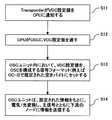
トランスポンダ103は、VDC設定値をCPU104に通知する(図10、S11)。CPU104は、受信したVDC設定値をOSC部105に出力する(S12)。OSC部105は、VDC設定値を所定の信号フォーマット(例えば、SONETのOC−3)の空きバイトに設定する(S13)。Here, the processing operation in the CPU 104 of FIG. 9 will be described with reference to the flowchart of FIG.
The transponder 103 notifies the CPU 104 of the VDC setting value (S11 in FIG. 10). The CPU 104 outputs the received VDC setting value to the OSC unit 105 (S12). The OSC unit 105 sets the VDC setting value to an empty byte of a predetermined signal format (for example, SONET OC-3) (S13).
次に、OSC部105は、所定の信号フォーマットのデータを電気/光変換し、変換した光信号を下流の波長分割多重装置に送信する(S14)。
上記の処理により、例えば、OSC部93は、OSC部91,94から転送されてくるVDC設定値、信号波長、ファイバ長などの分散情報を取得し、取得した分散情報に基づいて該当する経路、例えば、トランスポンダ22とトランスポンダ24とを結ぶ現用回線42に対するVDC設定値を求めることができる。そして、その現用回線42のVDC設定値を用いて予備回線43に対する好適なVDC設定値を設定することができる。これにより、回線障害が発生して予備回線に切り替える場合に、予備回線のVDC設定値を最適値に設定するまでの時間を短縮できる。Next, the OSC unit 105 performs electrical / optical conversion of data of a predetermined signal format, and transmits the converted optical signal to the downstream wavelength division multiplexing apparatus (S14).
With the above processing, for example, the
図11は、トランスポンダ103がVDC設定値を直接OSC部105に通知する場合の処理動作を示すフローチャートである。
トランスポンダ103が、OSC部105にVDC設定値を通知する(図11、S21)。OSC部105は、VDC設定値を所定の信号フォーマット(例えば、SONETのOC−3)のデータの空きバイトにセットする(S22)。FIG. 11 is a flowchart showing a processing operation when the transponder 103 notifies the OSC unit 105 of the VDC setting value directly.
The transponder 103 notifies the OSC unit 105 of the VDC setting value (S21 in FIG. 11). The OSC unit 105 sets the VDC setting value to an empty byte of data in a predetermined signal format (for example, SONET OC-3) (S22).
次に、OSC部105は、所定の信号フォーマットのデータを電気/光変換し、OSCを利用して下流のノードにVDC設定値(またはその他の情報)を送信する(S23)。
上記の処理により、受信側のトランスポンダは、伝送経路上の各トランスポンダにおける現用回線に対するVDC設定値等を取得することができるので、その現用回線と同じ物理回線に収容されている予備回線に対するVDC設定値の最適値を短時間で得ることができる。これにより、回線障害時の復旧時間を短縮できる。Next, the OSC unit 105 performs electrical / optical conversion on data of a predetermined signal format, and transmits the VDC setting value (or other information) to the downstream node using the OSC (S23).
By the above processing, the transponder on the receiving side can acquire the VDC setting value for the working line in each transponder on the transmission path, so the VDC setting for the protection line accommodated in the same physical line as that working line The optimum value can be obtained in a short time. Thereby, the recovery time at the time of a line failure can be shortened.
上述した第7の実施の形態によれば、各トランスポンダが自装置の分散情報をOSCを利用して他のトランスポンダに送信することができる。そして、各トランスポンダは、受信した分散情報を自装置の記憶回路に記憶し、自装置の予備回線に対するVDC設定値を予め算出して記憶しておくことができる。これにより、回線障害が発生したときに、可変分散補償回路は、短時間で予備回線の最適な分散補償値を決めることができ、回線障害の覆旧時間を短縮することができる。 According to the seventh embodiment described above, each transponder can transmit its own distributed information to other transponders using the OSC. Each transponder can store the received shared information in its own storage circuit, and calculate and store the VDC setting value for the protection line of its own device in advance. As a result, when a line failure occurs, the variable dispersion compensation circuit can determine the optimum dispersion compensation value for the protection line in a short time, and the time for covering the line failure can be shortened.
次に、図12は、第8の実施の形態のネットワークの構成を示す図である。この第8の実施の形態は、各トランスポンダが、Digital Wrapper、SONET(Synchronous Optical Network) DCC(Data Communication Channel)等により分散情報を送信するものである。 Next, FIG. 12 is a diagram illustrating a network configuration according to the eighth embodiment. In the eighth embodiment, each transponder transmits distributed information using a digital wrapper, a SONET (Synchronous Optical Network) DCC (Data Communication Channel), or the like.
波長分割多重装置は、長距離伝送を可能にするDigital Wrapperと呼ばれる技術を使用しているものがある。Digital Wrapperとは、データの前後をチャネルヘッダと順方向エラー訂正FECのデータでラップしたフレームフォーマットを指す。第8の実施の形態は、Digital Wrapper、あるいはSONET DCCのOverheadの空きバイトを使用して分散情報を送信する。 Some wavelength division multiplexing apparatuses use a technique called Digital Wrapper that enables long-distance transmission. Digital Wrapper refers to a frame format in which data is wrapped around a channel header and forward error correction FEC data. In the eighth embodiment, distributed information is transmitted using the empty bytes of the overhead of the Digital Wrapper or SONET DCC.
以下、Digital Wrapperを用いて分散情報を送信する場合について、図12を参照して説明する。以下の説明では、図1と同じ要素には同じ符号を付けてそれらの説明は省略する。 Hereinafter, a case where shared information is transmitted using the Digital Wrapper will be described with reference to FIG. In the following description, the same elements as those in FIG.
波長分割多重装置12は、トランスポンダ111と112を有する。Digital Wrapperは各トランスポンダにおいて生成及び終端される。
トランスポンダ111は、トランスポンダ21との間の現用回線41のパスa1に対するVDC設定値、光スイッチの向き、波長情報、ファイバタイプ、ファイバ長の一部または全部からなる分散情報とノードIDを、Digital Wrapperのオーバヘッドの空きバイトに挿入して他のトランスポンダに送信する。The wavelength
The
トランスポンダ23は、トランスポンダ112との間の現用回線41のパスb1に対するVDC設定値、光スイッチの向き、波長情報、ファイバタイプ、ファイバ長の一部または全部からなる分散情報とノードIDを、Digital Wrapperのオーバヘッドの空きバイトに挿入して他のトランスポンダに送信する。 The
トランスポンダ24は、トランスポンダ111から送信されてくるパスa1のVDC設定値と、トランスポンダ23から送信されてくるパスb1のVDC設定値に基づいて、同じ物理回線に収容されている予備回線44のパスc1に対するVDC設定値を算出することができる。 Based on the VDC setting value of the path a1 transmitted from the
上述した第8の実施の形態によれば、各トランスポンダのVDC設定値をDigital Wrapperを利用してネットワーク上に送出することで、各トランスポンダは自装置の上流(送信側)のトランスポンダのVDC設定値を取得することができる。従って、回線障害が発生する前、あるいは発生した後に、可変分散報償回路に予備回線に対する適正なVDC設定値を設定することができる。これにより、回線障害の復旧時間を短縮できる。 According to the eighth embodiment described above, by sending the VDC setting value of each transponder to the network using the Digital Wrapper, each transponder can set the VDC setting value of the transponder upstream (transmission side) of its own device. Can be obtained. Accordingly, an appropriate VDC setting value for the protection line can be set in the variable distributed award circuit before or after the line failure occurs. Thereby, the recovery time of a line failure can be shortened.
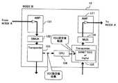
図13は、上述した第8の実施の形態の波長分割多重装置12の構成の一例を示す図である。図13の波長分割多重装置は、図1の伝送路の途中にある波長分割装置12(ノードB)に該当する。図1は、主信号がノードBをスルーで通過する場合の例であるが、図13は、ノードAから送信されてくる主信号がノードBのトランスポンダ123で受信され、図示しないルータまたは他の回線からトランスポンダ125に入力する主信号が、ノードC(波長分割多重装置13)に出力される場合を示している。 FIG. 13 is a diagram illustrating an example of the configuration of the wavelength
波長分割多重装置12は、波長分割多重装置11(ノードA)からの光信号を増幅する光増幅器121と、増幅された光信号を分波するデマルチプレクサ122と、分散補償、光/電気変換等を行うトランスポンダ123と、トランスポンダ123のVDC設定値を収集してトランスポンダ125に出力するCPU124と、トランスポンダ125と、光信号を多重するマルチプレクサ126と、マルチプレクサ126の出力光を増幅し、ノードC(光波長多重装置13)に接続する伝送路に送出する光増幅器127を有する。トランスポンダ123、125は、例えば、図5、図6または図7に示す構成を有する。 The wavelength
CPU124は、トランスポンダ123の現用回線41に対するVDC設定値を取得すると、そのVDC設定値をトランスポンダ125に出力する。トランスポンダ125は、VDC設定値等をDigital Wrapper、SONET DCC等の既知の信号フォーマットの空きバイトに挿入して伝送路に送出する。 When the
上述した第8の実施の形態によれば、各トランスポンダのVDC設定値等を既知の信号フォーマットの空きバイトを利用して送信し、各トランスポンダがその情報を受信し、記憶しておくことで、回線障害が発生する前に、可変分散補償回路に予備回線に対する適正なVDC設定値を設定することができる。これにより、回線障害の覆旧時間を短縮することができる。 According to the above-described eighth embodiment, the VDC setting value of each transponder is transmitted using an empty byte of a known signal format, and each transponder receives and stores the information. Before the line failure occurs, an appropriate VDC setting value for the protection line can be set in the variable dispersion compensation circuit. As a result, it is possible to shorten the time required for covering a line failure.
次に、上述した第7及び第8の実施の形態において、分散情報を挿入するOSC、Digital Wrapper、SONET DCCの信号フォーマットについて簡単に説明する。
図14は、ITU−T、G709で規定されるDigital Wrapperのフレームフォーマットを示す図である。Next, in the seventh and eighth embodiments described above, signal formats of OSC, Digital Wrapper, and SONET DCC into which shared information is inserted will be briefly described.
FIG. 14 is a diagram showing a frame format of the digital wrapper defined by ITU-T, G709.
図14に示すようにDigital Wrapperのフレームフォーマットは、オーバヘッドとエラー訂正コードFEC(Forward Error Correction)でデータをラップした構成を有する。第8の実施の形態で、Digital Wrapperを用いて分散情報を送信する場合には、図14のODUk(Optical Channel Data Unit)OH(overhead)131の中で、現在使用されていないRES(Reserved for future international Standardization)132に各トランスポンダのVDC設定値、波長情報等を挿入して送信する。 As shown in FIG. 14, the frame format of the digital wrapper has a configuration in which data is wrapped with overhead and an error correction code FEC (Forward Error Correction). In the eighth embodiment, when the distributed information is transmitted using the digital wrapper, the RES (Reserved for not used) in the ODUk (Optical Channel Data Unit) OH (overhead) 131 in FIG. (future international standardization) 132 VDC set values, wavelength information, etc. of each transponder are inserted and transmitted.
第7の実施の形態でOSCを利用して分散情報を送信する場合には、例えば、図15に示すSONETフレームのペイロードにトランスポンダのVDC設定値、信号の波長情報等を挿入して制御用チャネルで送信する。 When the distributed information is transmitted using the OSC in the seventh embodiment, for example, the control channel is inserted by inserting the VDC setting value of the transponder, the signal wavelength information, etc. into the payload of the SONET frame shown in FIG. Send with.
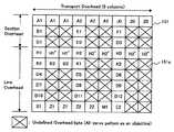
また、SONET DCCを利用して分散情報を送信する場合には、図16に×印で示すトランスポートオーバヘッド151の未定義バイト151aに、VDC設定値、信号の波長情報等を挿入して送信する。 Also, in the case where distributed information is transmitted using SONET DCC, the VDC set value, signal wavelength information, and the like are inserted into the
なお、各トランスポンダが所定の信号フォーマットで送信する情報は、VDC設定値そのものに限らず、受信側でVDC設定値が算出できるような情報でも良い。
次に、図17〜図19は、リングネットワーク以外の他のネットワーク形態を示す図である。以下の説明では、図1及びその他の図と同じ要素には同じ符号を付けてそれらの説明は省略する。The information transmitted by each transponder in a predetermined signal format is not limited to the VDC setting value itself, but may be information that allows the receiving side to calculate the VDC setting value.
Next, FIGS. 17 to 19 are diagrams showing other network configurations other than the ring network. In the following description, the same elements as those in FIG. 1 and other drawings are denoted by the same reference numerals, and the description thereof is omitted.
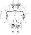
図17は、メッシュ構成のネットワークの例を示している。このメッシュ構成のネットワークに対しても上述した実施の形態と同じ方法で予備回線の最適な分散補償値を設定することができる。 FIG. 17 shows an example of a network having a mesh configuration. The optimum dispersion compensation value for the protection line can be set for the mesh-configured network in the same manner as in the above-described embodiment.
図17のメッシュ構成のネットワークは、図1の各ノードに加え、波長分割多重装置15(ノードE)を有し、波長分割多重装置15はトランスポンダ113、114を有する。 17 has a wavelength division multiplexing apparatus 15 (node E) in addition to each node of FIG. 1, and the wavelength
トランスポンダ22の予備回線47は、波長分割多重装置12、15を通過し、波長分割多重装置13のトランスポンダ24に入力している。他方、トランスポンダ21の現用回線41のパスa1は波長分割多重装置12のトランスポンダ111に入力し、トランスポンダ112の現用回線48のパスb1は波長分割多重装置15のトランスポンダ113に入力している。さらに、波長分割多重装置15(ノードE)の現用回線49のパスc1は、波長分割多重装置13のトランスポンダ23に入力している。 The
従って、トランスポンダ111におけるパスa1に対するVDC設定値(トランスポンダ12における残留分散も含む)と、トランスポンダ113におけるパスb1に対するVDC設定値と、トランスポンダ23におけるパスc1に対するVDC設定値が得られれば、それらのパスと同じ物理回線に存在する予備回線47のパスd1に対する適正な分散補償値を算出することができる。 Therefore, if a VDC setting value for the path a1 in the transponder 111 (including residual dispersion in the transponder 12), a VDC setting value for the path b1 in the
例えば、波長分割多重装置12が、トランスポンダ111のパスa1に対するVDC設定値(または分散補償値)を所定のデータフォーマットの空きバイトに挿入して各波長分割多重装置に送信する。同様、波長分割多重装置15が、トランスポンダ113のパスb1に対するVDC設定値を所定のデータフォーマットの空きバイトに挿入してネットワーク上に送出する。トランスポンダ23は、パスc1に対するVDC設定値をトランスポンダ24直接または所定のデータフォーマットの空きバイトに挿入して出力する。トランスポンダ24は、パスa1のVDC設定値+パスb1のVDC設定値+パスc1のVDC設定値を、予備回線47のパスd1のVDC設定値として求める。 For example, the wavelength
上記のメッシュ構成のネットワークにおいても、トランスポンダ24は、各トランスポンダ12、15、23から、それぞれのパスa1、b1、c1の分散補償値を取得することで、予備回線47の好適なVDC設定値を予め算出しておくことができる。これにより、予備回線47に切り替えて信号を疎通させるまでの復旧時間を短縮することができる。 Also in the network having the mesh configuration described above, the
図18はリニア構成のネットワークの一例を示す図である。図18の例では、現用回線41と予備回線44が同じ物理回線に収容されているときに、トランスポンダ23の現用回線41に対するVDC設定値から、同じ光回線に収容されている予備回線44の好適なVDC設定値を算出することができる。トランスポンダ24は、トランスポンダ23から現用回線41に対するVDC設定値を取得し、その取得した値に基づいて予備回線44に対するVDC設定値を設定することができる。 FIG. 18 is a diagram illustrating an example of a network having a linear configuration. In the example of FIG. 18, when the working
図19は、リニア構成のネットワークの他の例を示す図である。図19の例は、波長分割多重装置12が、トランスポンダ111とトランスポンダ112を有し、現用回線42aとその予備回線44aがトランスポンダ111に入力し、トランスポンダ112の現用回線42bがトランスポンダ24に入力している。現用回線41とその予備回線43は、トランスポンダ21から途中の波長分割多重装置12をスルーで通過して、トランスポンダ23に入力している。 FIG. 19 is a diagram illustrating another example of a network having a linear configuration. In the example of FIG. 19, the wavelength
今、トランスポンダ21とトランスポンダ23を結ぶ予備回線43が、現用回線42a、42bと同じ物理回線に収容されているとする。トランスポンダ23は、トランスポンダ111の現用回線42aに対するVDC設定値と、トランスポンダ24の現用回線42bに対するVDC設定値を取得することで予備回線43のVDC設定値を推測することができる。 Now, it is assumed that the
上記のリニア構成のネットワークにおいても、トランスポンダ23は、トランスポンダ111の現用回線42aに対するVDC設定値(または残留分散を示す値)と、トランスポンダ24の現用回線42bに対するVDC設定値を取得することで、予備回線43の好適なVDC設定値を予め算出することができる。これにより、回線障害が発生したときに、予備回線43に切り替えて短時間で信号を疎通させることができるので、障害の復旧時間を短縮できる。 Also in the network having the above linear configuration, the
メッシュ構成、あるいはリニア構成のネットワークにおいて、各トランスポンダが、VDC設定値等を取得する方法は、上述した第1〜第8の実施の形態の内の何れの方法でも良い。 In the mesh configuration or linear configuration network, the method for each transponder to acquire the VDC setting value or the like may be any of the above-described first to eighth embodiments.
本発明は上述した実施の形態に限らず、例えば、以下のような構成でも良い。
(1)トランスポンダは実施の形態に示した回路構成に限らず、他のものでも良い。トランスポンダの個数は2個に限らず、任意の個数で良い。
(2)トランスポンダが他のトランスポンダのVDC設定値を取得する機能はハードウェアに限らず、ソフトウェアにより実現しても良い。The present invention is not limited to the embodiment described above, and may be configured as follows, for example.
(1) The transponder is not limited to the circuit configuration shown in the embodiment, and other transponders may be used. The number of transponders is not limited to two and may be any number.
(2) The function of the transponder acquiring the VDC setting value of another transponder is not limited to hardware, and may be realized by software.
特許文献1には、複数の光伝送ルートの最適分散補償量を予めメモリに記憶しておき、ルート変更検出手段により光伝送ルートの変更が検出されると、メモリに記憶されている変更後のルートの最適分散補償量に応じて可変分散補償器の分散補償量を制御することが記載されている。
特許文献1:日本、特開2007−96499号公報In
Patent Document 1: Japan, Japanese Patent Application Laid-Open No. 2007-96499
Claims (16)
Translated fromJapanese前記予備回線と同じ光回線に収容されている現用回線に対する分散補償情報を、他の光伝送装置から取得する取得手段と、
前記取得手段で取得した分散補償情報に基づいて前記予備回線を伝送される光信号の分散を補償する分散補償手段とを備える波長分割多重装置。A wavelength division multiplexing device used in a network in which an optical transmission device on a transmission side and an optical transmission device on a reception side are connected by a working line and a protection line,
Obtaining means for obtaining dispersion compensation information for the working line accommodated in the same optical line as the protection line from another optical transmission device;
A wavelength division multiplexing apparatus comprising: dispersion compensation means for compensating dispersion of an optical signal transmitted through the protection line based on dispersion compensation information obtained by the obtaining means.
前記分散補償手段は、前記取得手段で受信した前記分散補償情報に基づいて前記予備回線に対する分散補償を行う請求項1記載の波長分割多重装置。The acquisition means receives dispersion compensation information sent over the network from another optical transmission device,
2. The wavelength division multiplexing apparatus according to claim 1, wherein the dispersion compensation means performs dispersion compensation for the protection line based on the dispersion compensation information received by the acquisition means.
前記取得手段は、前記第2の現用回線に対する分散補償情報を前記第3の光伝送装置から取得し、
前記分散補償手段は、前記取得手段で取得した分散補償情報に基づいて前記第1の予備回線を伝送される光信号の分散を補償する請求項1記載の波長分割多重装置。In the network, the first optical transmission device on the transmission side and the second optical transmission device on the reception side are connected by the first active line and the first protection line accommodated in different optical lines, The second working line of the third optical transmission device is accommodated in the same optical line as the first protection line;
The acquisition means acquires dispersion compensation information for the second working line from the third optical transmission device,
2. The wavelength division multiplexing apparatus according to claim 1, wherein the dispersion compensation means compensates for dispersion of an optical signal transmitted through the first protection line based on dispersion compensation information obtained by the obtaining means.
前記取得手段は、他の光伝送装置の記憶手段から自装置の予備回線と同じ光回線に収容されている現用回線に対する分散補償情報を取得する請求項1、2または3記載の波長分割多重装置。Storage means for storing dispersion compensation information in the dispersion compensation means, and storing the dispersion compensation information stored in another optical transmission device,
4. The wavelength division multiplexing apparatus according to claim 1, wherein the acquisition means acquires dispersion compensation information for the working line accommodated in the same optical line as the protection line of the own apparatus from the storage means of another optical transmission apparatus. .
前記設定手段は、他の光伝送装置の設定手段から自装置の予備回線と同じ光回線に収容されている現用回線に対する分散補償値を取得し、取得した前記分散補償値に基づいて前記分散補償手段の分散補償値を設定する請求項1、2または3記載の波長分割多重装置。The acquisition means has a setting means for setting the dispersion compensation value of the dispersion compensation means and outputting the set dispersion compensation value to another optical transmission device,
The setting means obtains a dispersion compensation value for the working line accommodated in the same optical line as the protection line of the own apparatus from the setting means of another optical transmission apparatus, and the dispersion compensation value is obtained based on the obtained dispersion compensation value. 4. The wavelength division multiplexing apparatus according to claim 1, wherein the dispersion compensation value of the means is set.
前記信号品質検出手段で検出される信号品質に基づいて修正した分散補償情報を算出する算出手段と、
前記算出手段で算出された分散補償情報を記憶すると共に、記憶した分散補償情報を他の光伝送装置に出力する記憶手段を有し、
前記取得手段は、他の光伝送装置の記憶手段から自装置の予備回線と同じ光回線に収容されている現用回線に対する分散補償情報を取得し、取得した前記分散補償情報に基づいて前記分散補償手段の分散補償値を設定する請求項1、2または3記載の波長分割多重装置。Signal quality detection means for detecting the signal quality of the main signal to be received;
Calculating means for calculating dispersion compensation information corrected based on the signal quality detected by the signal quality detecting means;
The dispersion compensation information calculated by the calculation means is stored, and storage means for outputting the stored dispersion compensation information to another optical transmission device,
The acquisition means acquires dispersion compensation information for the working line accommodated in the same optical line as the protection line of the own apparatus from the storage means of another optical transmission apparatus, and the dispersion compensation based on the acquired dispersion compensation information 4. The wavelength division multiplexing apparatus according to claim 1, wherein the dispersion compensation value of the means is set.
前記予備回線と同じ光回線に収容されている他の現用回線に対する分散補償情報を他の光伝送装置から取得し、
取得した分散補償情報に基づいて前記予備回線を伝送される光信号の分散を補償する光信号の分散補償方法。A dispersion compensation method for a network in which an optical transmission device on a transmission side and an optical transmission device on a reception side are connected by a working line and a protection line,
Obtaining dispersion compensation information from other optical transmission devices for other active lines accommodated in the same optical line as the protection line,
An optical signal dispersion compensation method for compensating for dispersion of an optical signal transmitted through the protection line based on acquired dispersion compensation information.
Applications Claiming Priority (1)
| Application Number | Priority Date | Filing Date | Title |
|---|---|---|---|
| PCT/JP2007/001446WO2009081449A1 (en) | 2007-12-20 | 2007-12-20 | Wavelength division multiplexing equipment and method for dispersion compensation of optical signal |
Publications (1)
| Publication Number | Publication Date |
|---|---|
| JPWO2009081449A1true JPWO2009081449A1 (en) | 2011-05-06 |
Family
ID=40800768
Family Applications (1)
| Application Number | Title | Priority Date | Filing Date |
|---|---|---|---|
| JP2009546869APendingJPWO2009081449A1 (en) | 2007-12-20 | 2007-12-20 | Wavelength division multiplexing apparatus and optical signal dispersion compensation method |
Country Status (4)
| Country | Link |
|---|---|
| US (1) | US20100247095A1 (en) |
| EP (1) | EP2224630A1 (en) |
| JP (1) | JPWO2009081449A1 (en) |
| WO (1) | WO2009081449A1 (en) |
Families Citing this family (10)
| Publication number | Priority date | Publication date | Assignee | Title |
|---|---|---|---|---|
| JP5166388B2 (en)* | 2009-11-02 | 2013-03-21 | 富士通テレコムネットワークス株式会社 | Optical transmission system |
| CN101895348A (en)* | 2010-07-19 | 2010-11-24 | 中兴通讯股份有限公司 | Dispersion compensation method of electric domain and filter parameter regulator |
| EP2493101A1 (en)* | 2011-02-24 | 2012-08-29 | Alcatel Lucent | Fast OMSP setup optimized for coherent detection |
| JP5747629B2 (en)* | 2011-04-18 | 2015-07-15 | 富士通株式会社 | Optical transmission device and optical switch device |
| US8873615B2 (en)* | 2012-09-19 | 2014-10-28 | Avago Technologies General Ip (Singapore) Pte. Ltd. | Method and controller for equalizing a received serial data stream |
| JP6640139B2 (en)* | 2017-03-16 | 2020-02-05 | Kddi株式会社 | Failure determination device, control method therefor, program, and optical fiber communication system |
| US10659184B2 (en)* | 2018-01-31 | 2020-05-19 | Fujitsu Limited | Optical transmission device, optical transmission method and optical transmission system |
| TWI690176B (en)* | 2018-06-11 | 2020-04-01 | 台達電子工業股份有限公司 | Intelligence-defined optical tunnel network system and network system control method |
| WO2022054250A1 (en)* | 2020-09-11 | 2022-03-17 | 日本電信電話株式会社 | Optical communication system, monitoring device, and monitoring method |
| CN115720123A (en)* | 2021-08-24 | 2023-02-28 | 中兴通讯股份有限公司 | Route switching method, node, routing device and storage medium |
Citations (3)
| Publication number | Priority date | Publication date | Assignee | Title |
|---|---|---|---|---|
| US7058297B1 (en)* | 2001-09-25 | 2006-06-06 | Ciena Corporation | Distributed processor modules and persistent storage in an optical network |
| JP2007096499A (en)* | 2005-09-27 | 2007-04-12 | Fujitsu Ltd | Optical receiver and dispersion compensation method in optical receiver |
| WO2008053567A1 (en)* | 2006-11-02 | 2008-05-08 | Fujitsu Limited | Optical receiver apparatus and received optical signal dispersion compensating method |
Family Cites Families (8)
| Publication number | Priority date | Publication date | Assignee | Title |
|---|---|---|---|---|
| US5978131A (en)* | 1998-04-07 | 1999-11-02 | Institut National D'optique | In-fiber two-stage amplifier providing WDM signal conditioning |
| US6157477A (en)* | 1998-05-27 | 2000-12-05 | Mci Communications Corporations | Bidirectional dispersion compensation system |
| US6850483B1 (en)* | 1999-11-30 | 2005-02-01 | Ciena Corporation | Method and system for protecting frame relay traffic over SONET rings |
| JP3757857B2 (en) | 2001-12-12 | 2006-03-22 | ソニー株式会社 | Data communication system, data transmission apparatus, data reception apparatus and method, and computer program |
| US20040208523A1 (en)* | 2002-01-30 | 2004-10-21 | Tellabs Operations, Inc. | Swept frequency reflectometry using an optical signal with sinusoidal modulation |
| US20040052530A1 (en)* | 2002-09-17 | 2004-03-18 | Cechan Tian | Optical network with distributed sub-band rejections |
| US7885541B2 (en)* | 2004-02-23 | 2011-02-08 | Dynamic Method Enterprises Limited | Method and apparatus for optical performance monitoring |
| US7787775B2 (en)* | 2006-05-08 | 2010-08-31 | Tellabs Operations, Inc. | Methods and apparatus for optical networks |
- 2007
- 2007-12-20EPEP07849874Apatent/EP2224630A1/ennot_activeWithdrawn
- 2007-12-20JPJP2009546869Apatent/JPWO2009081449A1/enactivePending
- 2007-12-20WOPCT/JP2007/001446patent/WO2009081449A1/ennot_activeCeased
- 2010
- 2010-06-14USUS12/814,646patent/US20100247095A1/ennot_activeAbandoned
Patent Citations (3)
| Publication number | Priority date | Publication date | Assignee | Title |
|---|---|---|---|---|
| US7058297B1 (en)* | 2001-09-25 | 2006-06-06 | Ciena Corporation | Distributed processor modules and persistent storage in an optical network |
| JP2007096499A (en)* | 2005-09-27 | 2007-04-12 | Fujitsu Ltd | Optical receiver and dispersion compensation method in optical receiver |
| WO2008053567A1 (en)* | 2006-11-02 | 2008-05-08 | Fujitsu Limited | Optical receiver apparatus and received optical signal dispersion compensating method |
Also Published As
| Publication number | Publication date |
|---|---|
| WO2009081449A1 (en) | 2009-07-02 |
| US20100247095A1 (en) | 2010-09-30 |
| EP2224630A1 (en) | 2010-09-01 |
Similar Documents
| Publication | Publication Date | Title |
|---|---|---|
| JPWO2009081449A1 (en) | Wavelength division multiplexing apparatus and optical signal dispersion compensation method | |
| US6532320B1 (en) | Equipments, transpondor and methods for optical fiber transmission | |
| US6864968B2 (en) | Method of measuring wavelength dispersion amount and optical transmission system | |
| CN1905415B (en) | Optical communication network, node device and path fault relief method | |
| US8280244B2 (en) | Optical ring network system | |
| US7447398B2 (en) | Optical crossconnect apparatus | |
| US8693864B2 (en) | Optical network system, optical redundant switching apparatus, and WDM apparatus | |
| JP6519162B2 (en) | Transmission system, transmission time difference measurement method in transmission system, and node | |
| US8265485B2 (en) | Optical transmission system and method for chromatic dispersion compensation | |
| US7877011B2 (en) | Optical switch and optical crossconnect apparatus | |
| JP4994300B2 (en) | Optical termination device | |
| JP6387965B2 (en) | Transmission apparatus, transmission system, transmission method, and storage medium storing program | |
| JP2008199284A (en) | Redundant switching system and redundant switching method in transmission system | |
| US7254333B2 (en) | Low-cost WDM terminal device accommodating plurality of client signal | |
| WO2008053567A1 (en) | Optical receiver apparatus and received optical signal dispersion compensating method | |
| JP4091634B2 (en) | Route determination method in optical signal transmission system | |
| US20020037013A1 (en) | Method of optically transmitting SDH or SONET signals | |
| JP3907939B2 (en) | Inverse wavelength division multiplexing optical transmission system | |
| EP1511331A1 (en) | Controller for switching wavelength-division multiplex optical signal | |
| JP2000286824A (en) | Wavelength division multiplex communication system | |
| US8611748B2 (en) | WDM optical transmission system and wavelength dispersion compensation method | |
| JP2012105114A (en) | Long-range optical transmission device and long-range optical transmission system | |
| JP2001352309A (en) | Wavelength division multiplex system |
Legal Events
| Date | Code | Title | Description |
|---|---|---|---|
| A131 | Notification of reasons for refusal | Free format text:JAPANESE INTERMEDIATE CODE: A131 Effective date:20120814 | |
| A521 | Request for written amendment filed | Free format text:JAPANESE INTERMEDIATE CODE: A523 Effective date:20121015 | |
| A02 | Decision of refusal | Free format text:JAPANESE INTERMEDIATE CODE: A02 Effective date:20130507 | |
| A521 | Request for written amendment filed | Free format text:JAPANESE INTERMEDIATE CODE: A523 Effective date:20130806 | |
| A911 | Transfer to examiner for re-examination before appeal (zenchi) | Free format text:JAPANESE INTERMEDIATE CODE: A911 Effective date:20130814 | |
| A912 | Re-examination (zenchi) completed and case transferred to appeal board | Free format text:JAPANESE INTERMEDIATE CODE: A912 Effective date:20131018 |