JPWO2009051179A1 - Carrier network connection device and carrier network - Google Patents
Carrier network connection device and carrier networkDownload PDFInfo
- Publication number
- JPWO2009051179A1 JPWO2009051179A1JP2009538131AJP2009538131AJPWO2009051179A1JP WO2009051179 A1JPWO2009051179 A1JP WO2009051179A1JP 2009538131 AJP2009538131 AJP 2009538131AJP 2009538131 AJP2009538131 AJP 2009538131AJP WO2009051179 A1JPWO2009051179 A1JP WO2009051179A1
- Authority
- JP
- Japan
- Prior art keywords
- network
- layer
- packet
- frame
- mpls
- Prior art date
- Legal status (The legal status is an assumption and is not a legal conclusion. Google has not performed a legal analysis and makes no representation as to the accuracy of the status listed.)
- Ceased
Links
- 238000006243chemical reactionMethods0.000claimsabstractdescription92
- 238000012546transferMethods0.000description41
- 230000005540biological transmissionEffects0.000description28
- 238000012545processingMethods0.000description28
- 238000012423maintenanceMethods0.000description7
- 238000000034methodMethods0.000description7
- 238000004891communicationMethods0.000description6
- 101100290389Schizosaccharomyces pombe (strain 972 / ATCC 24843) ceg1 geneProteins0.000description5
- 238000010586diagramMethods0.000description5
- 238000005516engineering processMethods0.000description5
- 230000008859changeEffects0.000description2
- 238000007689inspectionMethods0.000description2
- 238000012986modificationMethods0.000description2
- 230000004048modificationEffects0.000description2
- 101100503241Caenorhabditis elegans folt-1 geneProteins0.000description1
- 230000008901benefitEffects0.000description1
- 238000012790confirmationMethods0.000description1
- 239000004148curcuminSubstances0.000description1
- 238000013461designMethods0.000description1
- 230000003292diminished effectEffects0.000description1
- 230000006872improvementEffects0.000description1
- 230000008569processEffects0.000description1
Images


Classifications
- H—ELECTRICITY
- H04—ELECTRIC COMMUNICATION TECHNIQUE
- H04L—TRANSMISSION OF DIGITAL INFORMATION, e.g. TELEGRAPHIC COMMUNICATION
- H04L45/00—Routing or path finding of packets in data switching networks
- H—ELECTRICITY
- H04—ELECTRIC COMMUNICATION TECHNIQUE
- H04L—TRANSMISSION OF DIGITAL INFORMATION, e.g. TELEGRAPHIC COMMUNICATION
- H04L12/00—Data switching networks
- H04L12/28—Data switching networks characterised by path configuration, e.g. LAN [Local Area Networks] or WAN [Wide Area Networks]
- H04L12/46—Interconnection of networks
- H04L12/4633—Interconnection of networks using encapsulation techniques, e.g. tunneling
- H—ELECTRICITY
- H04—ELECTRIC COMMUNICATION TECHNIQUE
- H04L—TRANSMISSION OF DIGITAL INFORMATION, e.g. TELEGRAPHIC COMMUNICATION
- H04L12/00—Data switching networks
- H04L12/28—Data switching networks characterised by path configuration, e.g. LAN [Local Area Networks] or WAN [Wide Area Networks]
- H04L12/46—Interconnection of networks
- H04L12/4641—Virtual LANs, VLANs, e.g. virtual private networks [VPN]
- H04L12/4645—Details on frame tagging
- H04L12/465—Details on frame tagging wherein a single frame includes a plurality of VLAN tags
- H04L12/4658—Details on frame tagging wherein a single frame includes a plurality of VLAN tags wherein a VLAN tag represents a service provider backbone VLAN, e.g. B-Tag, S-Tag
- H—ELECTRICITY
- H04—ELECTRIC COMMUNICATION TECHNIQUE
- H04L—TRANSMISSION OF DIGITAL INFORMATION, e.g. TELEGRAPHIC COMMUNICATION
- H04L12/00—Data switching networks
- H04L12/28—Data switching networks characterised by path configuration, e.g. LAN [Local Area Networks] or WAN [Wide Area Networks]
- H04L12/46—Interconnection of networks
- H04L12/4641—Virtual LANs, VLANs, e.g. virtual private networks [VPN]
- H04L12/4645—Details on frame tagging
- H04L12/465—Details on frame tagging wherein a single frame includes a plurality of VLAN tags
- H04L12/4662—Details on frame tagging wherein a single frame includes a plurality of VLAN tags wherein a VLAN tag represents a service instance, e.g. I-SID in PBB
- H—ELECTRICITY
- H04—ELECTRIC COMMUNICATION TECHNIQUE
- H04L—TRANSMISSION OF DIGITAL INFORMATION, e.g. TELEGRAPHIC COMMUNICATION
- H04L45/00—Routing or path finding of packets in data switching networks
- H04L45/50—Routing or path finding of packets in data switching networks using label swapping, e.g. multi-protocol label switch [MPLS]
- H—ELECTRICITY
- H04—ELECTRIC COMMUNICATION TECHNIQUE
- H04L—TRANSMISSION OF DIGITAL INFORMATION, e.g. TELEGRAPHIC COMMUNICATION
- H04L45/00—Routing or path finding of packets in data switching networks
- H04L45/66—Layer 2 routing, e.g. in Ethernet based MAN's
- H—ELECTRICITY
- H04—ELECTRIC COMMUNICATION TECHNIQUE
- H04L—TRANSMISSION OF DIGITAL INFORMATION, e.g. TELEGRAPHIC COMMUNICATION
- H04L45/00—Routing or path finding of packets in data switching networks
- H04L45/68—Pseudowire emulation, e.g. IETF WG PWE3
Landscapes
- Engineering & Computer Science (AREA)
- Computer Networks & Wireless Communication (AREA)
- Signal Processing (AREA)
- Computer Security & Cryptography (AREA)
- Data Exchanges In Wide-Area Networks (AREA)
- Details Of Aerials (AREA)
- Support Of Aerials (AREA)
- Small-Scale Networks (AREA)
Abstract
Translated fromJapaneseDescription
Translated fromJapanese本発明は、通信事業者用基幹ネットワーク接続装置および通信事業者用基幹ネットワークに関する。 The present invention relates to a trunk network connection device for a telecommunications carrier and a trunk network for a telecommunications carrier.
通信事業者用基幹ネットワークシステムを構築するアーキテクチャとして、RFC3032に規定されるMPLS(Multiprotocol Label Switching)が広く知られている。MPLSでは、転送パケットにデータ長の短い「ラベル」が付与され、パケット転送時には該ラベルのみを読み取って、ルータ間の転送が行われる。これにより、ルータにおいてデータ長の長いIPヘッダを読み取る必要がなく、高速なルーティングが可能となる。MPLSで用いられるラベルは、LDP(Label Distribution Protocol)などのプロトコルを用いてMPLSルータ同士で経路情報の交換を行ない割り当てられる。また、MPLSでは、複数のラベルを積層(スタック)させることにより、VPN(Virtual Private Network)や階層化パス等を実現することができる。そのため、現在、特に大規模な基幹ネットワークにおいてこのMPLSが広く利用されている。 As an architecture for constructing a backbone network system for a communication carrier, MPLS (Multiprotocol Label Switching) defined in RFC 3032 is widely known. In MPLS, a “label” having a short data length is added to a transfer packet, and only the label is read at the time of packet transfer, and transfer between routers is performed. As a result, it is not necessary for the router to read an IP header having a long data length, and high-speed routing is possible. Labels used in MPLS are assigned by exchanging route information between MPLS routers using a protocol such as LDP (Label Distribution Protocol). In MPLS, it is possible to realize a VPN (Virtual Private Network), a hierarchical path, and the like by stacking a plurality of labels. Therefore, at present, this MPLS is widely used particularly in large-scale backbone networks.
MPLSを用いたネットワークシステムの構成例を図1に示す。図1のネットワークシステムは、MPLSドメイン4とユーザ網2から構成される。MPLSドメイン4とユーザ網2とは、プロバイダ・エッジ・ルータPEによって接続されている。そして、プロバイダ・エッジ・ルータPEは、MPLSドメイン4内のプロバイダ・ルータPを介して、別のユーザ網2と接続された別のプロバイダ・エッジ・ルータPEに接続される。ユーザ網2から送信される転送パケットは、プロバイダ・エッジ・ルータPEにて、転送パケットの宛先となるIPアドレスに基づいたラベルが付与され、プロバイダ・ルータPでラベルが付け替えられながら転送される。 A configuration example of a network system using MPLS is shown in FIG. The network system shown in FIG. 1 includes an
MPLSドメイン4においてVPNを実現する方法として、プロバイダ・エッジ・ルータPEにおいて、ユーザ網2から転送されるパケットに2種類のMPLSラベルを付与する方法がある。ここで付与されるラベルの一つは上述のMPLSドメイン4内を転送するための転送用のラベルであり、もう一つはVPN識別用のラベルである。プロバイダ・ルータP間では、転送用ラベルに基づいてパケットが転送される。そしてVPN識別ラベルは、プロバイダ・ルータPにおいては参照も変更もされず、受信側のプロバイダ・エッジ・ルータPEにおいてのみ参照される。そして、受信側のプロバイダ・エッジ・ルータPEにてVPN識別用ラベルに基づいてVPNが識別されることにより、送信側のプロバイダ・エッジ・ルータPEと受信側のプロバイダ・エッジ・ルータPEとの間で仮想リンク(Pseudo Wire)が形成される。 As a method for realizing VPN in the
また、さらに上記のようなMPLSを利用したVPNにおいて、イーサネットフレームをMPLSパケットでカプセル化して転送するEoMPLS(Ethernet Over MPLS)と呼ばれる技術も知られている(尚、「イーサネット」及び「Ethernet」は、米国Xerox Corp.の商標である)。EoMPLSを介して相互に接続されたネットワーク間ではイーサネットフレームを透過的に送受信できるというメリットがある。また、既設のMPLS網をそのまま流用できるため、プロバイダ側の設備負担も比較的低く抑えられる。 Further, in VPN using MPLS as described above, a technique called EoMPLS (Ethernet Over MPLS) that encapsulates and transfers an Ethernet frame with an MPLS packet is also known (“Ethernet” and “Ethernet” Is a trademark of Xerox Corp., USA). There is an advantage that Ethernet frames can be transmitted and received transparently between networks connected to each other via EoMPLS. In addition, since the existing MPLS network can be used as it is, the equipment burden on the provider side can be kept relatively low.
上述のように、基幹網にMPLSドメインを使用したネットワークシステムでは、ラベルのスタッキングを行うことによって、VPNなどの高機能なネットワークを実現することが可能となっている。しかしながら、ラベルをスタックすることにより、IPパケットに付加されるヘッダ数が増加し、ネットワークの安定性が逓減してしまうといった問題もある。例えばEoMPLSでは、少なくとも5つのヘッダが使用されており、これ以上のヘッダの積層はキャリア・グレードの高い信頼性が要求されるネットワークを構築する上では好ましくない。実際に、このように高度に積層されたヘッダを使用するMPLSネットワークにおいて、複雑なヘッダ構造が一因となって発生した重大な障害も報告されている。また、MPLSのラベルは、あて先となるノードのIPアドレスに基づいて付与されるため、ネットワークの拡大に伴うスケーラビリティに限界があるといった問題もある。 As described above, in a network system using an MPLS domain for the backbone network, it is possible to realize a high-performance network such as VPN by stacking labels. However, stacking labels increases the number of headers added to an IP packet, and there is a problem that the stability of the network is diminished. For example, in EoMPLS, at least five headers are used, and further stacking of headers is not preferable in constructing a network that requires high carrier grade reliability. In fact, in an MPLS network using such highly stacked headers, a serious failure that has been caused by a complicated header structure has also been reported. In addition, since the MPLS label is assigned based on the IP address of the destination node, there is a problem in that there is a limit to scalability associated with network expansion.
このような問題を解決するため、イーサネット技術を利用して基幹ネットワークを構築する、PBB(Provider Backbone Bridges)という広域イーサネット技術が注目を集めている。PBBは、VPNサービスをイーサネット(レイヤー2)で提供するためのものである。図2は、PBBドメイン3を用いたネットワークシステムの構成を示す図である。図2のネットワークシステムは、PBBドメイン3とユーザ網2とが接続されて構成される。PBBドメイン3とユーザ網2とはプロバイダ・エッジ・スイッチPESによって接続される。そして、プロバイダ・エッジ・スイッチPESは、プロバイダ・スイッチPSを介して、別のユーザ網2と接続された別のプロバイダ・エッジ・スイッチPESに接続される。 In order to solve such a problem, a wide area Ethernet technology called PBB (Provider Backbone Bridges), which constructs a backbone network using the Ethernet technology, has attracted attention. PBB is for providing a VPN service by Ethernet (layer 2). FIG. 2 is a diagram showing a configuration of a network system using the
PBBドメイン3では、プロバイダ・エッジ・スイッチPESにて、ユーザ網20から送信されるイーサネットフレーム(MACフレーム)にPBB用の新たなヘッダを付けて、PBBドメイン3内の転送を行う。新たに付けられたヘッダには、あて先MACアドレス(B−DA)と送信元MACアドレス(B−SA)のフィールドがあり、これらのフィールドにはあて先および送信元となるPBBドメイン3のプロバイダ・エッジ・スイッチPESのMACアドレスが入る。さらに、V−LAN識別子であるB−VIDを含むB−TAGと呼ばれるVLAN識別用のタグと、I−TAGと呼ばれるユーザ識別用のタグが、ヘッダとして新たに付加される。このようなPBB網において使用される、ユーザ網から転送されるMACフレームをPBB網のMACフレーム内にカプセル化したフレームのことを、MAC−in−MAC形式フレームと呼ぶ。プロバイダ・スイッチPSは、プロバイダ・エッジ・スイッチPESのMACアドレスに基づいて、カプセル化したユーザMACフレームの転送を行なう。これにより、プロバイダ・スイッチPSでは、プロバイダ・エッジ・スイッチPESのMACアドレスのみを学習すればよいため、ノードの増加による影響が少なく、優れたスケーラビリティを実現することができる。また、MPLSを用いる場合に比べて、ヘッダの数を少なくすることが可能となるため、安定性にも優れている。 In the
さらに、上記PBBを用いたネットワークシステムにおいて、経路制御を行うトラフィック・エンジニアリング(TE)を実現するための技術として、ノーテル社が提唱するPBB―TE、もしくはPBT(Provider Backbone Transport)と呼ばれる技術も開発されている。PBTを用いたネットワークシステムの構成も図2と同様である。PBTでは、プロバイダ・エッジ・スイッチPESにて付与されるB−TAGに含まれるB−VIDとB−DAとの組み合わせによって、MPLSのラベルパスのようなポイント・ツー・ポイントのパスを明示的に設定することを可能としている。これにより、B−VIDを使ったマルチパスの設定が可能となり、帯域をより効率的に利用できるようになる。更に、IEEE802.1ag、ITU−T Y.1731等で規定されるOAM(Operation, Administration and Maintenance:保守運用)の採用により、広域イーサネットにおけるキャリア・グレードの保守運用機能も実現されている。 Furthermore, in the network system using the PBB, a technology called PBB-TE or PBT (Provider Backbone Transport) proposed by Nortel is also developed as a technology for realizing traffic engineering (TE) for route control. Has been. The configuration of the network system using PBT is the same as that shown in FIG. In the PBT, a point-to-point path such as an MPLS label path is explicitly set by a combination of B-VID and B-DA included in the B-TAG assigned by the provider edge switch PES. It is possible to do. Thereby, multipath setting using B-VID becomes possible, and the bandwidth can be used more efficiently. Further, IEEE 802.1ag, ITU-T Y. With the adoption of OAM (Operation, Administration and Maintenance) defined in 1731 and the like, a carrier-grade maintenance operation function in wide-area Ethernet is also realized.
上述のようにPBTは、従来の広域イーサネットには欠けていたトラフィック・エンジニアリング技術や保守運用機能(OAM)も備え、MPLS網に代わる次世代ネットワークアーキテクチャの候補として高く評価されている。 As described above, the PBT has traffic engineering technology and maintenance and operation function (OAM) that are lacking in the conventional wide area Ethernet, and is highly evaluated as a candidate for a next-generation network architecture that replaces the MPLS network.
しかしながら、PBTは、イーサネット・スイッチによって構成されるレイヤ2ネットワークであるため、既存の大規模基幹IP網であるMPLS網を構成しているレイヤ3ルータの資産を活用することができない。そのため、PBTを採用するためには、NGN(New Generation Network)等の全く新規なネットワークシステムとして、PBTのためのレイヤ2ネットワークを構築する必要がある。PBTはイーサネット・スイッチによって構成される安価なネットワークシステムではあるが、それでも既存のMPLS基幹網を全て新規なPBT網に置き換えることは、通常は経済的に許容されない。すなわち、既存のMPLS網が現実に直面しているスケーラビリティ等の問題は、PBTによっても解決されない。 However, since the PBT is a layer 2 network composed of Ethernet switches, the assets of the
本発明は、このような従来のIP基幹網のスケーラビリティを改善するネットワークシステム及び該ネットワークシステムを構成するネットワーク接続装置を提供することを目的とする。 An object of the present invention is to provide a network system that improves the scalability of such a conventional IP backbone network and a network connection device that constitutes the network system.
本発明の実施形態により、レイヤ2上で形成される仮想リンク(Pseudo Wire)とレイヤ3上で形成される仮想リンクを連結するネットワーク接続装置であって、第1の仮想リンクを形成するレイヤ2ネットワークのエッジ・スイッチとして動作するスイッチング部と、第2の仮想リンクを形成するレイヤ3ネットワークのエッジ・ルータとして動作するルーティング部と、レイヤ2ネットワークのフレームとレイヤ3ネットワークのパケットとを相互に変換する変換部とを備えるネットワーク接続装置が提供される。 According to an embodiment of the present invention, a network connection device that connects a virtual link formed on layer 2 and a virtual link formed on
上記構成を備えたネットワーク接続装置によれば、レイヤ3ネットワーク上に形成される仮想リンクとレイヤ2ネットワーク上に形成される仮想リンクとを接続することが可能となる。このようなネットワーク接続装置を使用することにより、レイヤ3ネットワークの外周に拡張性の高いレイヤ2ネットワークを増設することが可能になり、既存のレイヤ3ネットワークの拡張性を改善することができる。 According to the network connection device having the above configuration, it is possible to connect a virtual link formed on the
この場合においてレイヤ2ネットワークは広域イーサネット網であり、レイヤ3ネットワークはIP網であることが望ましい。さらに、IP網はEoMPLS網であり、広域イーサネット網はPBB−TE網であっても良い。 In this case, the layer 2 network is preferably a wide area Ethernet network, and the
また、上記変換部は、レイヤ2ネットワークのフレームにおけるヘッダと、レイヤ3のパケットにおけるヘッダを付け替える、もしくはレイヤ2ネットワークのフレームに、レイヤ3のパケットにおけるヘッダを付け加えて、レイヤ2ネットワークのフレームとレイヤ3ネットワークのパケットとを相互に変換する構成としても良い。 Further, the conversion unit replaces the header in the layer 2 network frame and the header in the
この場合において、レイヤ2ネットワークのフレームは、PBB−TEフレームであり、レイヤ3のパケットはEoMPLSパケットであり、変換部は、PBB−TEフレームのI−TAG値とEoMPLSパケットのVPN識別用ラベルとを相互に変換する構成とすることが好ましい。 In this case, the frame of the layer 2 network is a PBB-TE frame, the
さらに、変換部は、広域イーサネット網におけるイーサネットOAMフレームと、MPLS網におけるMPLS−OAMパケットとを相互に変換する構成を備えていることが好ましい。 Furthermore, it is preferable that the conversion unit has a configuration for mutually converting an Ethernet OAM frame in the wide area Ethernet network and an MPLS-OAM packet in the MPLS network.
また、本実施形態において、レイヤ3ネットワークと、レイヤ3ネットワークと1つ以上の接続点で接続されたレイヤ2ネットワークとからなるネットワークであって、複数のエッジを有し、該複数のエッジの異なる2つの間で第1の仮想リンク(pseudo wire)を形成しており、該第1の仮想リンクは、レイヤ2ネットワーク上に形成された第2の仮想リンクとレイヤ3ネットワーク上に形成された第3の仮想リンクとが前記1つ以上の接続点において連結されたものであることを特徴とするネットワークが提供される。 Further, in the present embodiment, the network includes a
上記構成を備えたネットワークでは、レイヤ3ネットワーク上に形成される仮想リンクとレイヤ2ネットワーク上に形成される仮想リンクとを接続されるため、レイヤ3ネットワークの外周に拡張性の高いレイヤ2ネットワークを増設することが可能になり、既存のレイヤ3ネットワークの拡張性を改善することができる。 In the network having the above configuration, since the virtual link formed on the
この場合において、レイヤ2ネットワークはMPLS網であり、レイヤ3ネットワークはPBB−TE網であることが望ましい。また、第3の仮想リンクはEoMPLSの仮想リンクであり、第1の仮想リンクの両端のエッジはPBB−TE網上に設けられていても良い。さらに、高可用性を必要とするサービスには第2の仮想リンクのみが使用される構成としても良い。この場合の高可用性を必要とするサービスは緊急通報サービスである。 In this case, the layer 2 network is preferably an MPLS network, and the
また、上記ネットワークは、仮想リンクを連結するネットワーク接続装置と、当該ネットワークの経路情報の収集と明示的な経路設定を行う網管理装置とを更に備えており、該網管理装置は、ネットワーク接続装置を介して、当該ネットワークの経路情報の収集および明示的なポイント・ツー・ポイントの経路設定を行うよう構成されても良い。 The network further includes a network connection device that links the virtual links, and a network management device that collects route information of the network and performs explicit route setting, and the network management device is a network connection device. The network may be configured to collect route information of the network and explicitly set a point-to-point route.
このように、上記構成を備えたネットワーク接続装置およびネットワークにより、レイヤ3ネットワークの外周に拡張性の高いレイヤ2ネットワークを増設することが可能になり、従来のIP基幹網のスケーラビリティを改善することができる。 As described above, the network connection device and the network having the above-described configuration makes it possible to add a highly scalable layer 2 network to the outer periphery of the
1 ネットワークシステム
20 ユーザ網
30 PBTドメイン
40 MPLSドメイン
100 IPパケット
200 ユーザMACフレーム
230 ユーザMACタグ
300 PBTフレーム
350 PBTタグ
400 MPLSパケット
420 MPLSラベル
421 VLAN識別ラベル
422 転送ラベル
500 制御部
600 PBTスイッチ部
700 MPLSルータ部
800 データ変換部
810 パケット変換部
820 OAM変換部
900 データ処理部
CE カスタマ・エッジ
PB 事業者中継網
PC パーソナル・コンピュータ
PCE プロバイダ・コア・エッジ
PE プロバイダ・エッジ
PS プロバイダ・スイッチ
P プロバイダ・ルータ
PR プロバイダ・エッジ・ルータ1
以下、図面を参照して、本発明の実施形態について説明する。 Embodiments of the present invention will be described below with reference to the drawings.
まず、本発明の実施形態であるネットワークシステム1の全体構成について説明する。図3はネットワークシステム1のトポロジを示す図である。ネットワークシステム1は、MPLSドメイン40とPBTドメイン30からなる事業者中継網PBと、複数のユーザ網20から構成される。 First, the overall configuration of the network system 1 according to the embodiment of the present invention will be described. FIG. 3 is a diagram showing the topology of the network system 1. The network system 1 includes a carrier relay network PB composed of an
MPLSドメイン40は、ラベルに基づいてパケットの転送を行うMPLSルータによって統合された単一ドメインのレイヤ3ネットワークである。また、PBT(PBB−TE)ドメイン30は、PBT対応のイーサネット・スイッチで構成された単一ドメインのレイヤ2ネットワークである。さらに、ユーザ網20は、IEEE802.1Qに対応したネットワーク・インタフェース・カード(NIC)を有するパーソナル・コンピュータPC等のノードから構成されたLAN(Local Area Network)である。 The
事業者中継網PBは、MPLSドメイン40の周囲がPBTドメイン30で囲まれた構造をもつ。すなわち、ユーザ網20はPBTドメイン30にのみ接続されている。そして、MPLSドメイン40は、事業者中継網PBのコアに位置し、PBTドメイン30を介してユーザ網20に接続されている。そのため、本実施形態のネットワークシステム1においては、PBTドメイン30のみを拡張させることでユーザ網20の増加に対応することが可能となる。 The carrier relay network PB has a structure in which the
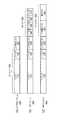
次に各ドメインの具体的な構成について説明する。ユーザ網20を構成するPC等の各ノードは、上述の通りIEEE802.1Qに対応したネットワーク・インタフェース・カードを有しており、802.1Qに準拠したイーサネットフレーム(以下、「ユーザMACフレーム200」という)を交換することによって通信を行う。図4(a)にユーザMACフレーム200のフォーマットを示す。ユーザMACフレーム200は、ペイロード110とIPヘッダ120から構成されるIPパケット100に、イーサネットヘッダ(以下、「ユーザMACタグ230」という)が付加された構造をもつ。 Next, a specific configuration of each domain will be described. Each node such as a PC constituting the
ユーザ網20は、イーサネット・ブリッジであるカスタマ・エッジCEを介して事業者中継網PBのPBTドメイン30(具体的にはプロバイダ・エッジPE)に接続されている。ユーザ網20に属するPCから送信される、別のユーザ網に属するノード(送信先のPC)を宛先とするユーザMACフレーム200は、カスタマ・エッジCEからPBTドメイン30のプロバイダ・エッジPEへ転送される。 The
図3に戻って、PBTドメイン30は、プロバイダ・エッジPE、プロバイダ・スイッチPS、及びプロバイダ・コア・エッジPCEの3種類のPBT規格に準拠したイーサネット・スイッチから構成されている。プロバイダ・エッジPEは、事業者中継網PBとユーザ網20とを接続するエッジ・スイッチであり、ユーザ網20内で交換されるユーザMACフレーム200と、PBTドメイン30内で交換されるMAC−in−MAC形式のPBTフレーム300とを相互に変換する。 Returning to FIG. 3, the
PBTドメイン30内で転送されるPBTフレーム300のフォーマットを図4(b)に示す。PBTフレーム300は、ユーザ網20からのユーザMACフレーム200に、PBTドメイン30内でのスイッチングに使用するPBTタグ350が付加された構造となっている。すなわち、PBTフレーム300は、ユーザMACフレーム200をフレームごとカプセル化した構造となっている。PBTタグ350は、送信先のプロバイダ・エッジPEのMACアドレスが指定されたB−DA310、送信元のプロバイダ・エッジPEのMACアドレスを示すB―SA320、VLAN識別のためのB−VIDを含むB−TAG330、およびユーザ/サービス識別のためのI−SID(サービス・インスタンスID)を含むI−TAG340から構成される。PBTドメイン30では、B−TAG330に含まれるB−VIDに基づき識別されるVLANによって、イーサネットの仮想リンク(Pseudo Wire)が形成され、PBTドメイン30のエッジ間でユーザMACフレーム200が透過的に転送される。 The format of the PBT frame 300 transferred within the
また、本実施形態のプロバイダ・コア・エッジPCEは、PBTドメイン30とMPLSドメイン40とを接続する機能を有するネットワーク接続装置である。そのためプロバイダ・コア・エッジPCEは、PBTドメイン30のエッジ・スイッチとしての機能と、MPLSドメイン40のエッジ・ルータとしての機能とを併せ持っており、PBTドメイン30とMPLSドメイン40とのインタフェースの役割を果たす。具体的には、プロバイダ・コア・エッジPCEにて、PBTドメイン30内で交換されるPBTフレーム300とMPLSドメイン40内で交換される後述のMPLSパケット400とが相互に変換される。プロバイダ・コア・エッジPCEの具体的な機能の詳細は後述する。 The provider core edge PCE of this embodiment is a network connection device having a function of connecting the
事業者中継網PBのコアを構成するMPLSドメイン40は、プロバイダ・ルータPと上述のプロバイダ・コア・エッジPCEの2種類のMPLSルータによって構成される。プロバイダ・コア・エッジPCEは、上述のとおりMPLSドメイン40のエッジ・ルータとしての機能を備えたネットワーク接続装置であり、PBTドメイン30とMPLSドメイン40とを接続する。プロバイダ・ルータPは、MPLSドメイン40を構成するMPLSルータのみに接続されている。そして、後述の方法でプロバイダ・コア・エッジPCEにて変換されたMPLSパケット400は、プロバイダ・ルータPを介して、受信側のプロバイダ・コア・エッジPCEに転送される。 The
MPLSドメイン40で転送されるMPLSパケット400のフォーマットを図4(c)に示す。MPLSラベル420は、MPLSドメイン40内を転送するための転送用のラベル422とVPNを識別するためのVPN識別用ラベル421から構成される。MPLSパケット400は、PBTフレーム300におけるPBTタグ350を、MPLSラベル420に置き換えられた構成となっている。このVPN識別用ラベル421により、MPLSドメイン40のエッジ間(すなわち、プロバイダ・コア・エッジPCE間)で仮想リンクが形成される。また、本実施形態のMPLSパケット400は、イーサネットフレームであるユーザMACフレーム200にラベルが付加されるEoMPLS形式のMPLSパケットとなっている。実際には、更にレイヤ2のタグが付加されたフレームとしてMPLSドメイン40を構成するリンク上をデータが転送されるが、MPLS網におけるレイヤ2の処理は周知であるため、これについては説明を省略する。 The format of the MPLS packet 400 transferred in the
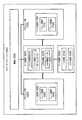
次に、本発明の実施形態のプロバイダ・コア・エッジPCEの構成について説明する。図5は、プロバイダ・コア・エッジPCEの構成を示すブロック図である。プロバイダ・コア・エッジPCEは、装置全体を統合的に制御する制御部500と、PBTスイッチとして機能するPBTスイッチ部600と、MPLSルータとして機能するMPLSルータ部700と、転送フレーム/パケットおよびOAMフレーム/パケットの変換を行なうデータ変換部800と、トラフィック・エンジニアリング(TE)や保守運用(OAM)に関する処理を行うデータ処理部900とから構成される。 Next, the configuration of the provider core edge PCE according to the embodiment of the present invention will be described. FIG. 5 is a block diagram showing the configuration of the provider core edge PCE. The provider core edge PCE includes a control unit 500 that integrally controls the entire apparatus, a PBT switch unit 600 that functions as a PBT switch, an MPLS router unit 700 that functions as an MPLS router, a transfer frame / packet, and an OAM frame. / Data conversion unit 800 that performs packet conversion, and data processing unit 900 that performs processing related to traffic engineering (TE) and maintenance operation (OAM).
PBTスイッチ部600は、PBTフレーム300を受信するフレーム受信部622と、PBTフレーム300を送信するフレーム送信部624とを含むフレーム転送部620を有する。また、MPLSルータ部700は、MPLSパケット400を受信するパケット受信部722と、MPLSパケット400を送信するパケット送信部724とを含むパケット転送部720を有する。 The PBT switch unit 600 includes a frame transfer unit 620 including a frame reception unit 622 that receives the PBT frame 300 and a frame transmission unit 624 that transmits the PBT frame 300. The MPLS router unit 700 also includes a packet transfer unit 720 that includes a packet receiving unit 722 that receives the MPLS packet 400 and a packet transmission unit 724 that transmits the MPLS packet 400.
データ変換部800は、PBTフレーム300とMPLSパケット400とを相互に変換するパケット変換部810と、イーサネットOAMフレームと、MPLS−OAMパケットとを相互に変換するOAM変換部820とから構成される。OAMフレーム(OAMパケット)とは、保守・管理の対象となるスイッチ(ルータ)に対して定期的に送信される検査用のフレーム(パケット)である。 The data conversion unit 800 includes a packet conversion unit 810 that converts the PBT frame 300 and the MPLS packet 400 to each other, and an OAM conversion unit 820 that converts the Ethernet OAM frame and the MPLS-OAM packet to each other. An OAM frame (OAM packet) is an inspection frame (packet) that is periodically transmitted to a switch (router) to be maintained and managed.
パケット変換部810は、PBTフレーム300とMPLSパケット400を相互に変換する際に参照されるパケット変換テーブル811aおよび811bを有している。パケット変換テーブル811a、811bは、それぞれ転送方向毎に用意されている。図6にパケット変換テーブル811a、811bの一例を示す。 The packet conversion unit 810 includes packet conversion tables 811a and 811b that are referred to when the PBT frame 300 and the MPLS packet 400 are converted to each other. Packet conversion tables 811a and 811b are prepared for each transfer direction. FIG. 6 shows an example of the packet conversion tables 811a and 811b.
図6(a)は、PBTフレーム300をMPLSパケット400へ変換する際に参照されるパケット変換テーブル811aを示す。パケット変換テーブル811aには、受信したPBTフレーム300のI−TAG(a1、a2、・・・)と、MPLSパケット400の送信ポート番号(b1、b2、・・・)、VPN識別ラベル値(c1、c2、・・・)および転送ラベル値(d1、d2、・・・)が含まれる。また、パケット変換テーブル811aには、さらに、経路障害などに対応するために、代替のルートを示す代替用の送信ポート番号(b100、b101、・・・)および転送ラベル値(d100、d101、・・・)が含まれている。これにより、後述するOAM処理部920において経路障害などを検出した場合には、制御部500から、代替の送信ポート番号および転送ラベル値に基づいて、PBTフレーム300の変換を行なうようパケット変換部800への指示がなされる。 FIG. 6A shows a packet conversion table 811 a referred to when converting the PBT frame 300 into the MPLS packet 400. The packet conversion table 811a includes the I-TAG (a1, a2,...) Of the received PBT frame 300, the transmission port numbers (b1, b2,...) Of the MPLS packet 400, the VPN identification label value (c1). , C2,...) And transfer label values (d1, d2,...). The packet conversion table 811a further includes alternative transmission port numbers (b100, b101,...) Indicating alternative routes and transfer label values (d100, d101,. ··)It is included. As a result, when a path failure or the like is detected in the OAM processing unit 920 described later, the packet converting unit 800 converts the PBT frame 300 from the control unit 500 based on the alternative transmission port number and transfer label value. Is instructed.
図6(b)は、MPLSパケット400をPBTフレーム300へ変換する際に参照されるパケット変換テーブル811bを示す。パケット変換テーブル811bには、受信するMPLSパケット400のVPN識別ラベル値(c1、c2、・・・)と、送信するPBTフレーム300の送信ポート番号(b11、b12、・・・)、I−TAG(a1、a2、・・・)、B−TAG(e1、e2、・・・)およびB−DA(MC20、MC32、・・・)などのPBTタグの値が含まれる。パケット変換テーブル811bにも、パケット変換テーブル811aと同様に、経路障害などに対応するために、代替のルートを示す代替用の送信ポート番号(b100、b101、・・・)およびB−TAG330の値(e100、e101、・・・)が含まれている。そして、経路障害などを検出した場合には、代替の送信ポート番号およびB−TAGの値に基づいて、MPLSパケット400の変換を行なうよう制御部500からパケット変換部800へ指示がなされる。 FIG. 6B shows a packet conversion table 811 b that is referred to when the MPLS packet 400 is converted into the PBT frame 300. In the packet conversion table 811b, the VPN identification label values (c1, c2,...) Of the received MPLS packet 400, the transmission port numbers (b11, b12,...) Of the PBT frame 300 to be transmitted, I-TAG. PBT tag values such as (a1, a2,...), B-TAG (e1, e2,...) And B-DA (MC20, MC32,...) Are included. Similarly to the packet conversion table 811a, the packet conversion table 811b also includes an alternative transmission port number (b100, b101,...) Indicating the alternative route and the value of the B-
図5に戻って、OAM変換部820は、PBTドメイン30内で交換されるイーサネットOAM(例えば、ITU−T Y.1731, IEEE802.1ag等)によるOAMフレームと、MPLSドメイン40内で交換されるMPLS−OAM(例えば、ITU−T Y.1711, LSP ping, LSP traceroute等)によるOAMパケットを相互に変換する変換部である。OAM変換部820は、OAM変換テーブル822を有しており、このテーブルに基づいて、イーサネットOAMフレームとMPLS−OAMパケットの変換を行なう。OAM変換テーブル822には、それぞれ同様の情報を含むイーサネットOAMフレームとMPLS−OAMパケットが対応付けられている。 Returning to FIG. 5, the OAM conversion unit 820 is exchanged in the
データ処理部900は、トラフィック・エンジニアリング(TE)に関する処理を行うTE処理部910と、OAMに関する処理を行うOAM処理部920を有する。TE処理部910は、PBTドメイン30においてB−TAGに含まれるB−VIDとB−DAとの組み合わせによる経路の確定や、MPLSドメイン40におけるリンクステート情報の交換によるラベルの付与など、TEに必要な処理を行う処理部である。また、TE処理部910で処理された情報は、データ変換部800に送信され、データ変換部800は、この情報に基づいてパケット変換テーブル811aおよび811bを作成/更新する。また、OAM処理部920は、受信したOAMフレームおよびOAMパケットに基づいて接続性の検証や、経路障害の有無などを確認する処理を行う処理部である。OAM処理部920にて経路障害などを確認した場合は、制御部500に経路障害についての通知を行い、上述のように代替の経路を選択するようになっている。 The data processing unit 900 includes a TE processing unit 910 that performs processing related to traffic engineering (TE) and an OAM processing unit 920 that performs processing related to OAM. The TE processing unit 910 is necessary for the TE such as confirmation of a route by a combination of B-VID and B-DA included in the B-TAG in the
以上のように、本実施形態のプロバイダ・コア・エッジPCEは、PBTドメイン30のエッジ・スイッチとしての機能およびMPLSドメイン40のエッジ・ルータとしての機能の他に、MPLSパケット400とPBTフレーム300を相互に変換するためのパケット変換部810を備えている。このような機能を備えたプロバイダ・コア・エッジPCEによって、PBTドメイン30におけるPBTフレーム300の仮想リンクと、MPLSドメイン40におけるMPLSパケット400の仮想リンクを接続することが可能となる。そのため、プロバイダ・コア・エッジPCE以外のルータやスイッチについては、PBT又はEoMPLS規格に対応した標準的な装置を使用して事業者中継網PBを構築することができる。従って、少ない追加投資によって拡張性の高いシステムに変更することが可能となる。 As described above, the provider core edge PCE according to the present embodiment includes the MPLS packet 400 and the PBT frame 300 in addition to the function as the edge switch of the
また、さらに本実施形態のプロバイダ・コア・エッジPCEは、PBTドメイン30内で交換されるイーサネットOAMによるOAMフレームと、MPLSドメイン40内で交換されるMPLS−OAMによるOAMパケットとを相互に変換することが可能なOAM変換部820を備えている。この構成により、事業者中継網PB全体の保守運用が一元化されるため、保守運用に要する負担や時間が大きく軽減され、低コストで高い可用性が実現される。また、OAMの変換処理を行う要素をプロバイダ・コア・エッジPCEのみに設けることにより、プロバイダ・コア・エッジPCE以外のノードについては、PBT又はEoMPLS規格に対応した標準的な装置を使用することができる。従って、少ない追加投資によって保守運用を実現しつつ拡張性の高いシステムに変更することが可能となる。 Furthermore, the provider core edge PCE of this embodiment mutually converts an OAM frame by Ethernet OAM exchanged in the
次に、本実施形態のネットワークシステム1におけるエンド・ツー・エンド通信の一例を、図7を参照しながら説明する。図7は、図3におけるユーザ網20a内にあるPC1からユーザ網20b内にあるPC2までのエンド・ツー・エンドの通信経路を示した図である。 Next, an example of end-to-end communication in the network system 1 of the present embodiment will be described with reference to FIG. FIG. 7 is a diagram showing an end-to-end communication path from the PC 1 in the
ユーザ網20aとユーザ網20bは、同一のIEEE802.1Q VLANを構成している。ユーザ網20aにおいては、このVLANは802.1QフレームのC−VID「C1」によって定義される。 The
ユーザ網20aのPC1のレイヤ3エンティティは、ユーザ網20bに存在するPC2のIPアドレス(例えば、「10.0.0.1.132」)を宛先IPアドレスとするIPパケット100を生成して、レイヤ2エンティティに渡す。IPパケット100を受け取ったPC1のレイヤ2エンティティは、IPパケット100のあて先IPアドレスと転送テーブルを参照して、宛先MACアドレスをPC2のMACアドレス「M20」、送信元MACアドレスをPC1のMACアドレス「M10」、C−VIDを「C1」とするユーザMACタグ230をIPパケットに付加し、図7(a)に示されるユーザMACフレーム200aを生成して、カスタマ・エッジCE1へ送信する。 The
ユーザマックフレーム200aを受信したカスタマ・エッジCE1は、転送テーブルを参照して、ユーザMACフレーム200aの宛先MACアドレス「M20」から転送先ポートを特定し、プロバイダ・エッジPE1が接続されたポートに転送する。 The customer edge CE1 that has received the user mac frame 200a refers to the forwarding table, identifies the forwarding port from the destination MAC address “M20” of the user MAC frame 200a, and forwards it to the port to which the provider edge PE1 is connected. To do.
ユーザMACフレーム200aを受信したプロバイダ・エッジPE1は、C−VIDの値「C1」および宛先MACアドレス「M20」に基づき、転送テーブルを参照して、ユーザMACフレーム200aを、PBTドメイン30内を転送するための図7(b)に示すPBTフレーム300aに変換する。具体的には、転送テーブルからVLAN識別用のB−TAG「e1」、ユーザ識別用のI−TAG「a1」、及びPBTドメイン30における宛先ノードであるプロバイダ・エッジPE2のMACアドレス「MC20」(B−DA)、送信元のプロバイダ・エッジPE1のMACアドレス「MC10」(B-SA)を取得し、ユーザMACフレーム200aに付加する。プロバイダ・エッジPE1にて生成されたPBTフレーム300aは、所定の送信ポートからプロバイダ・スイッチPS1へ送信される。 Upon receiving the user MAC frame 200a, the provider edge PE1 transfers the user MAC frame 200a in the
PBTフレーム300aを受信したプロバイダ・スイッチPS1は、転送テーブルを参照して、B−TAGに含まれるB−VIDの値およびB−DAの値から次の中継ノード(プロバイダ・スイッチPS2)を特定して送信する。PBTフレーム300bを受信したプロバイダ・スイッチPS2においても同様の処理が行われ、PBTフレーム300aがプロバイダ・コア・エッジPCE1へ転送される。このように、PBTドメイン300においては、B−TAGに含まれるB−VIDの値に基づき識別されるVLANによって形成された仮想リンク内をユーザMACフレーム200が転送される。 The provider switch PS1 that has received the
プロバイダ・コア・エッジPCE1は、フレーム受信部622にてPBTフレーム300aを受信すると、PBTフレーム300aをデータ変換部800のパケット変換部810に渡す。パケット変換部810は、図6(a)に示されるパケット変換テーブル811aを参照して、PBTフレーム300aのI−TAGの値(「a1」)から、MPLSドメイン40におけるネクストホップの送信ポート番号「b1」、VPN識別ラベル値「c1」および転送ラベル値「d1」を取得する。そして、PBTフレーム300aからPBTタグを削除し、パケット変換テーブル811aから取得したVPN識別ラベル値及び転送ラベル値をPBTフレーム300aに付加して図7(c)に示すMPLSパケット400aを生成する。その後、生成されたMPLSパケット400aは、パケット送信部724に渡され、送信ポート「b1」から次の中継ノードであるプロバイダ・ルータP1に転送される。 When the provider core edge PCE1 receives the
MPLSパケット400aを受信したプロバイダ・ルータP1は、自身が所有するラベルテーブルを参照して、MPLSパケット400aの受信ポート番号と転送ラベル「d1」から、ネクストホップの送信ポート番号及び転送ラベル「d2」を取得する。そして、プロバイダ・ルータP1は、転送ラベルを付け換えてMPLSパケット400bを生成し、次の中継ノードであるプロバイダ・ルータP2へ所定の送信ポートから転送する。 The provider router P1 that has received the
プロバイダ・ルータP2、P3においてもプロバイダ・ルータP1と同様の処理を行い、転送ラベル「d4」が付与されたMPLSパケット400d(図7(d))がプロバイダ・コア・エッジPCE2に転送される。このように、MPLSドメイン400においては、VPN識別ラベル値の値は変更されずに、転送ラベルの値のみ付け替えられて転送される。これにより、MPLSドメイン400においては、VPN識別ラベルの値に基づき識別されるVPNによって形成された仮想リンク内をMPLSパケットが転送される。 The provider routers P2 and P3 perform the same processing as the provider router P1, and the
プロバイダ・コア・エッジPCE2は、パケット受信部720にてMPLSパケット400dを受信し、受信したパケット400dをデータ変換部800のパケット変換部810に渡す。パケット変換部810は、図6(b)に示されるパケット変換テーブル811bを参照して、MPLSパケット400dのVPN識別ラベル値「c1」から、PBTドメインにおける次のリンクの送信ポート番号「b11」、B−DA「MC20」、I−TAG「a1」およびB−TAG「e1」の各情報を取得する。そして、MPLSパケット400dからVPN識別ラベル及び転送ラベルを削除し、パケット変換テーブル811bから取得したB−DA「MC20」、I−TAG「a1」、B−TAG「f1」、および自身のMACアドレス「MC30」を含むPBTタグを付加して、図7(e)に示されるPBTフレーム300bを生成する。その後、生成されたPBTフレーム300bは、フレーム送信部624に送られ、次の中継ノードであるプロバイダ・スイッチPS3に、送信ポート「b11」から転送される。 The provider core edge PCE2 receives the
プロバイダ・スイッチPS3、PS4は、プロバイダ・スイッチPS1と同様の処理を行い、それぞれPBTフレーム300bをプロバイダ・スイッチPS4、プロバイダ・エッジPE2へ所定の送信ポートから転送する。 The provider switches PS3 and PS4 perform the same processing as the provider switch PS1, and respectively transfer the
PBTフレーム300bを受信したプロバイダ・エッジPE2は、転送テーブルを参照してPBTフレーム300bのI−TAGおよびB−TAGの値から次の中継ノードとなるカスタマ・エッジCEへの送信ポート番号を特定する。そして、PBTフレーム300bからPBTタグを除去し、ユーザMACフレーム200aをカスタマ・エッジCE2へ所定の送信ポートから送信する。 The provider edge PE2 that has received the
ユーザMACフレーム200aを受信したカスタマ・エッジCE2は、転送テーブルを参照して、宛先MACアドレス「M20」およびC−VID「C1」から転送ポートを特定して、PC2へユーザMACフレーム200bを転送する。PC2のレイヤ2エンティティは、ユーザMACフレーム200aを受信すると、ユーザMACタグを除去し、IPパケットをレイヤ3エンティティに渡し、最後にレイヤ3エンティティがIPパケットを除去してペイロードを取得して受信が完了する。 The customer edge CE2 that has received the user MAC frame 200a refers to the forwarding table, identifies the forwarding port from the destination MAC address “M20” and C-VID “C1”, and forwards the user MAC frame 200b to the PC2. . When receiving the user MAC frame 200a, the layer 2 entity of PC2 removes the user MAC tag and passes the IP packet to the
また、ユーザ網20aのカスタマ・エッジCE1から、検査のためのイーサネットOAMフレームが送信されると、該イーサネットOAMフレームはPBTドメイン30内のプロバイダ・エッジPE1およびプロバイダ・スイッチPS1およびPS2によって転送され、プロバイダ・コア・エッジPCE1で受信される。プロバイダ・コア・エッジPCE2は、受信したイーサネットOAMフレームをデータ変換部800のOAM変換部820に渡す。OAM変換部820は、OAM変換テーブル822を参照して、イーサネットOAMフレームを、MPLS−OAMパケットへ変換して、次の中継ノードであるプロバイダ・ルータP1へ転送する。そして、MPLSドメイン40内のプロバイダ・ルータP1〜P3を転送され、プロバイダ・コア・エッジPCE2に受信されると、プロバイダ・コア・エッジPCE2のOAM処理部820にて、MPLS−OAMパケットから、イーサネットOAMフレームへ変換され、PBTドメイン30のプロバイダ・スイッチPSへ転送される。 When an Ethernet OAM frame for inspection is transmitted from the customer edge CE1 of the
以上が本発明の実施形態の説明であるが、本発明の範囲は上記実施形態に限定されるものではない。例えば、上述の実施形態ではPBTドメイン30は単一のドメインであるが、複数のドメインに分割されていてもよい。ドメインを分割することにより、各ドメインに含まれるノード数が減少するため、ドメイン内の経路管理が容易になり、更に高い拡張性が実現される。更に、あるドメインに深刻な障害が発生しても、その影響が他のドメインを構成するノードに波及する危険性が低くなるため、より信頼性の高いネットワークを構築することができる。なお、この場合には、なるべく任意のドメインがダウンしても迂回ルートを確保できるようにドメイン分割をデザインするとよい。 The above is the description of the embodiment of the present invention, but the scope of the present invention is not limited to the above embodiment. For example, in the above-described embodiment, the
また、上述の実施形態においては、プロバイダ・コア・エッジPCEは、PBTドメイン30とMPLSドメイン40を同じ階層で接続する場合(Peering)を例に説明したが、本発明はこれに限定されるものではない。例えば、PBTドメイン30とMPLSドメイン40が異なる階層で接続された、いわゆるOverlayネットワークにおいても、本発明を適用可能である。ここで、Overlayの場合は、プロバイダ・コア・エッジPCEにおいて、PBTドメイン30で転送されるPBTフレーム300を、MPLSドメイン40で転送されるMPLSパケット400にカプセル化するように構成される。 Further, in the above-described embodiment, the provider core edge PCE has been described as an example in which the
この場合のMPLSパケット400eのフォーマットを図8に示す。図8のMPLSパケット400eは、プロバイダ・コア・エッジPCEのパケット変換部810にて、パケット変換テーブル811aを参照して生成される。具体的には、上記実施形態と同様に、PBTフレーム300のI−TAGの値から、MPLSドメイン40における、ネクストホップの送信ポート番号、VPN識別ラベル値および転送ラベル値を取得する。そして、PBTフレーム300に該VPN識別ラベル値及び転送ラベル値を付加してMPLSパケット400eを生成する。 The format of the
その後は、上記実施形態と同様に、MPLSドメイン40のプロバイダ・ルータPにてMPLSパケットの転送ラベルのみが書き換えられながら受信側のプロバイダ・コア・エッジPCEに転送される。受信側のプロバイダ・コア・エッジPCEは、ラベルテーブルを参照して、受信したMPLSパケット400eのVPN識別ラベル値から、ネクストホップのポート番号を特定する。その後、VPN識別ラベル値および転送ラベル値を除去し、元のPBTフレーム300に戻して次の中継ノードへ所定の送信ポートから転送する。このような構成とすることで、PBTフレーム300が、MPLSドメイン400の仮想リンクを透過的に転送される。そして、受信側のプロバイダ・コア・エッジPCEにおいては、MPLSパケットからPBTフレームへのパケット変換処理を行う必要がなく、またそのためのパケット変換テーブル811bを所有する必要もないため、負荷が軽減される。 After that, as in the above embodiment, the provider router P in the
また、上述の実施形態においては、プロバイダ・コア・エッジPCEがPBTドメイン30のエッジ・スイッチとしての機能と、MPLSドメイン40のエッジ・ルータとしての機能とを併せ持つ構成としたが、本発明はこれに限定されない。図9は、本発明の変形例となるネットワークシステム10のトポロジを示す。図9に示されるように、ネットワークシステム10は、上記実施形態におけるプロバイダ・コア・エッジPCEにてPBTドメイン30とMPLSドメイン40を接続する替わりに、PBTドメイン30のエッジ・スイッチとなるプロバイダ・エッジPEと、MPLSドメイン40のエッジ・ルータとなるプロバイダ・エッジ・ルータPRとを、IEEE802.1ahで規定されるE−NNI(Ethernet Network to Network Interface)によって接続するよう構成される。 In the above-described embodiment, the provider core edge PCE has a function as an edge switch of the
この場合、PBTドメイン30のプロバイダ・エッジPEからE−NNIを介してプロバイダ・エッジ・ルータPRへPBTフレームが転送される。ここで、プロバイダ・エッジ・ルータPRは、MPLSドメイン40のエッジ・ルータとしての機能およびMPLSパケット400とPBTフレーム300を相互に変換するためのパケット変換機能、およびOAM変換機能を備えている。これらの機能については、上記実施形態のプロバイダ・コア・エッジPCEにおけるパケット変換処理部810、OAM変換処理部820と同様のため、説明は省略する。 In this case, the PBT frame is transferred from the provider edge PE of the
このように構成することで、MPLSドメイン40におけるプロバイダ・エッジ・ルータPRにてMPLSパケット400とPBTフレーム300を相互に変換するためのパケット変換機能、およびOAM変換機能を備える構成とするだけで、PBTドメイン30においては、既存のエッジ・スイッチおよびインターフェース(E−NNI)のみを利用して、本発明を実現することが可能となる。そのため、既存のネットワークシステムに対して、少しの改良を加えるだけで、PBTドメイン30とMPLSドメイン40とを接続することが可能となる。 With this configuration, the provider edge router PR in the
さらに、上記実施形態では、プロバイダ・エッジPE1から事業者中継網PBに入ったパケットは、PBTドメイン30を通過した後、一度MPLSドメイン40を通り、再び反対側のPBTドメインを通過してプロバイダ・エッジPE2から事業者中継網PBを出るという経路を通っている。しかし、必ずしもPBTドメイン−MPLSドメイン−PBTドメインという経路を通る必要はなく、PBTドメイン30だけを通って事業者中継網PBから出る経路に設定することも可能である。また、場合によっては、PBTドメイン30とMPLSドメイン40とを何度も行き来した方が有利な場合もあり、そのように経路を設定することも可能である。更に、上述の実施形態では、全てのプロバイダ・エッジPEがPBTドメイン30上に設けられているが、一部のプロバイダ・エッジPEをMPLSドメイン40上に設けた構成にしてもよい。この場合、MPLSドメイン40上のプロバイダ・エッジPEから入って、MPLSドメイン40上の別のプロバイダ・エッジPEから抜ける経路をとってもよいし、PBTドメイン30上のプロバイダ・エッジ30から抜ける経路をとることもできる。 Furthermore, in the above-described embodiment, the packet that has entered the carrier relay network PB from the provider edge PE1 passes through the
また、MPLSドメイン40とPBTドメイン30での通信の信頼性を比較すると、レイヤ2のみで動作するPBTドメイン30における通信の方が圧倒的に高い信頼性を有している。従って、例えば緊急電話などの高い信頼性が要求されるサービスに対しては、PBTドメインのみを通過させるように経路設定することが望ましい。 Further, when comparing the reliability of communication between the
また、上記実施形態においては、プロバイダ・コア・エッジPCEにおいて、TE及びOAMを制御するデータ処理部を備える構成としていたが、これに限定されるものではない。例えば、ネットワークシステム1内に事業者中継網PB全体のTE及びOAMに関する制御を行うネットワーク・マネジメント・システム(NMS)を設けても良い(不図示)。この場合、プロバイダ・コア・エッジPCEをNMSに接続することで、NMSからのTEやOAMに関する情報に基づき、パケット変換テーブル811aおよび811bを作成/更新したり、代替の転送先を選択したりすることができる。さらに、上記実施形態においては、パケット変換テーブル811aおよび811bはTE処理部910で処理された情報に基づき作成/更新される構成としたが、その他にも、オペレータによる手動作業によって作成/更新されても良い。 In the above embodiment, the provider core edge PCE has the data processing unit for controlling the TE and OAM. However, the present invention is not limited to this. For example, a network management system (NMS) that performs control related to TE and OAM of the entire operator relay network PB may be provided in the network system 1 (not shown). In this case, by connecting the provider core edge PCE to the NMS, the packet conversion tables 811a and 811b are created / updated based on the information about the TE and OAM from the NMS, and an alternative transfer destination is selected. be able to. Furthermore, in the above embodiment, the packet conversion tables 811a and 811b are configured to be created / updated based on information processed by the TE processing unit 910. However, the packet conversion tables 811a and 811b are also created / updated manually by an operator. Also good.
本発明の実施形態により、通信事業者用基幹ネットワークのスケーラビリティを確保することを実現するためにレイヤ3ネットワークのIP網からなる通信事業者ドメインと、レイヤ3ネットワークのIP網からなるユーザ網との間に、レイヤ2ネットワークのイーサネットドメインを配し、前記レイヤ2ネットワークのイーサネットドメインを拡大することによってユーザ網の増加に対応するシステムにおいてレイヤ2上で形成される第1の仮想リンク(Pseudo Wire)とレイヤ3上で形成される第2の仮想リンクを連結するネットワーク接続装置であって、前記第1の仮想リンクを形成するレイヤ2ネットワークのエッジ・スイッチとして動作するスイッチング部と、前記第2の仮想リンクを形成するレイヤ3ネットワークのエッジ・ルータとして動作するルーティング部と、前記レイヤ2ネットワークのフレームと、前記レイヤ3ネットワークのパケットとを相互に変換する変換部と、を備えるネットワーク接続装置が提供される。この構成において、レイヤ3ネットワークとレイヤ2ネットワークとは、1つ以上の接続点で相互に接続されたネットワークを構成し、ネットワークは、複数のエッジを有し、該複数のエッジの異なる2つの間で仮想リンクを形成しており、ネットワークに形成された仮想リンクは、レイヤ2ネットワーク上に形成された第1の仮想リンクとレイヤ3ネットワーク上に形成された第2の仮想リンクとが前記1つ以上の接続点において連結されたものである。 According to the embodiment of the present invention, in order to realize the scalability of the backbone network for a carrier, a carrier domain composed of an IP network of a
この場合において、変換部は、前記レイヤ2ネットワークのフレームに含まれるユーザを識別する値と、前記レイヤ3ネットワークのパケットに含まれる仮想リンクを識別する値とを相互に変換するように構成されていても良い。また、レイヤ2ネットワークで転送されるフレームは、ユーザ網からのフレームに、レイヤ2ネットワーク内でのスイッチングに使用するタグを付加することによって、ユーザ網からのフレームをフレームごとカプセル化した構造をしており、変換部は、ユーザ網からのタグを残したまま、レイヤ2ネットワーク内でのスイッチングに使用するタグを、レイヤ3からなる通信事業者ドメインのラベルに変換するように構成されていても良い。また、レイヤ2ネットワークはPBTドメインであり、レイヤ3からなる通信事業者ドメインはMPLS網であり、PBTドメイン内で転送されるPBTフレームは、ユーザ網からのユーザMACフレームをフレームごとカプセル化し、ユーザ網のVLANタグとPBTタグとをスタックさせた構造をしており、変換部は、VLANタグを残したままPBTタグのみを、MPLS網で使用するMPLSラベルに変換するように構成されていても良い。また、レイヤ2ネットワークのフレームは、PBB−TEフレームであり、レイヤ3のパケットはEoMPLSパケットであり、変換部は、PBB−TEフレームのI−TAG値とEoMPLSパケットのVPN識別用ラベルとを相互に変換するように構成されていても良い。また、レイヤ2ネットワークは広域イーサネット網であり、変換部は、広域イーサネット網におけるイーサネットOAMフレームと、MPLS網におけるMPLS−OAMパケットとを相互に変換するように構成されていても良い。また、レイヤ2ネットワークはPBB-TE網であり、第1の仮想リンクの両端のエッジはPBB-TE網上に設けられていても良い。また、高可用性を必要とするサービスには第1の仮想リンクのみが使用されても良い。高可用性を必要とするサービスは緊急通報サービスであっても良い。 In this case, the conversion unit is configured to mutually convert a value for identifying a user included in the frame of the layer 2 network and a value for identifying a virtual link included in the packet of the
ネットワークには、当該ネットワークの経路情報の収集と明示的な経路設定を行う網管理装置が備えられ、該網管理装置は、ネットワーク接続装置を介して、当該ネットワークの経路情報の収集および明示的なポイント・ツー・ポイントの経路設定を行うように構成されていても良い。また、ネットワーク接続装置は、1つ以上の接続点の少なくとも1つに配置され、変換部は、PBB−TEフレームとMPLSパケットとを変換するように構成されていても良い。また、ネットワーク接続装置は、1つ以上の接続点の少なくとも1つに配置され、変換部は、イーサネットOAMフレームとMPLS−OAMパケットとを変換するように構成されていても良い。また、レイヤ2ネットワークはPBB-TE網であり、PBB−TE網は複数のドメインから構成されていても良い。 The network is provided with a network management device that collects route information of the network and performs explicit route setting. The network management device collects route information of the network and expresses it explicitly via the network connection device. It may be configured to perform point-to-point route setting. The network connection device may be arranged at at least one of the one or more connection points, and the conversion unit may be configured to convert the PBB-TE frame and the MPLS packet. The network connection device may be arranged at at least one of the one or more connection points, and the conversion unit may be configured to convert the Ethernet OAM frame and the MPLS-OAM packet. Further, the layer 2 network is a PBB-TE network, and the PBB-TE network may be composed of a plurality of domains.
また、本発明の実施形態によれば、通信事業者用基幹ネットワークのスケーラビリティを確保するためのシステムであって、レイヤ3ネットワークのIP網からなる通信事業者ドメインと、レイヤ3ネットワークのIP網からなるユーザ網との間に配されたレイヤ2ネットワークのイーサネットドメインと、レイヤ2上で形成される第1の仮想リンク(Pseudo Wire)とレイヤ3上で形成される第2の仮想リンクを連結するネットワーク接続装置と、を備えるシステムが提供される。この構成において、ネットワーク接続装置は、第1の仮想リンクを形成するレイヤ2ネットワークのエッジ・スイッチとして動作するスイッチング部と、第2の仮想リンクを形成するレイヤ3ネットワークのエッジ・ルータとして動作するルーティング部と、レイヤ2ネットワークのフレームと、レイヤ3ネットワークのパケットとを相互に変換する変換部と、を備える。更に、レイヤ3ネットワークと前記レイヤ2ネットワークとは、1つ以上の接続点で相互に接続されたネットワークを構成し、ネットワークは、複数のエッジを有し、該複数のエッジの異なる2つの間で仮想リンクを形成しており、ネットワークに形成された仮想リンクは、レイヤ2ネットワーク上に形成された第1の仮想リンクとレイヤ3ネットワーク上に形成された第2の仮想リンクとが1つ以上の接続点において連結されたものであり、レイヤ2ネットワークに追加的に配されたスイッチによって前記イーサネットドメインが拡大され、ユーザ網の増加に対応する。 Further, according to the embodiment of the present invention, there is provided a system for ensuring the scalability of a trunk network for a telecommunications carrier, comprising a telecommunications carrier domain composed of an IP network of a
上記構成を備えたシステムによれば、レイヤ3ネットワーク上に形成される仮想リンクとレイヤ2ネットワーク上に形成される仮想リンクとを接続することが可能となる。したがって、レイヤ3ネットワークの外周に拡張性の高いレイヤ2ネットワークを増設することが可能になり、既存のレイヤ3ネットワークの拡張性を改善することができる。 According to the system having the above configuration, a virtual link formed on the
この場合において、変換部は、レイヤ2ネットワークのフレームに含まれるユーザを識別する値と、レイヤ3ネットワークのパケットに含まれる仮想リンクを識別する値とを相互に変換するように構成されていても良い。また、レイヤ2ネットワークで転送されるフレームは、ユーザ網からのフレームに、レイヤ2ネットワーク内でのスイッチングに使用するタグを付加することによって、ユーザ網からのフレームをフレームごとカプセル化した構造をしており、変換部は、ユーザ網からのタグを残したまま、レイヤ2ネットワーク内でのスイッチングに使用するタグを、レイヤ3からなる通信事業者ドメインのラベルに変換するように構成されていても良い。また、レイヤ2ネットワークはPBTドメインであり、レイヤ3からなる通信事業者ドメインはMPLS網であり、PBTドメイン内で転送されるPBTフレームは、ユーザ網からのユーザMACフレームをフレームごとカプセル化し、ユーザ網のVLANタグとPBTタグとをスタックさせた構造をしており、変換部は、VLANタグを残したままPBTタグのみを、MPLS網で使用するMPLSラベルに変換するように構成されていても良い。また、レイヤ2ネットワークのフレームは、PBB−TEフレームであり、レイヤ3のパケットはEoMPLSパケットであり、変換部は、PBB−TEフレームのI−TAG値とEoMPLSパケットのVPN識別用ラベルとを相互に変換するように構成されていても良い。また、レイヤ2ネットワークは広域イーサネット網であり、変換部は、広域イーサネット網におけるイーサネットOAMフレームと、MPLS網におけるMPLS−OAMパケットとを相互に変換するように構成されていても良い。また、レイヤ2ネットワークはPBB-TE網であり、第1の仮想リンクの両端のエッジはPBB-TE網上に設けられていても良い。また、高可用性を必要とするサービスには第1の仮想リンクのみが使用されても良い。高可用性を必要とするサービスは緊急通報サービスであっても良い。 In this case, the conversion unit may be configured to mutually convert a value for identifying a user included in a layer 2 network frame and a value for identifying a virtual link included in a
また、当該ネットワークの経路情報の収集と明示的な経路設定を行う網管理装置を更に備えており、該網管理装置は、前記ネットワーク接続装置を介して、当該ネットワークの経路情報の収集および明示的なポイント・ツー・ポイントの経路設定を行うように構成されていても良い。ネットワーク接続装置は、前記1つ以上の接続点の少なくとも1つに配置され、変換部は、PBB−TEフレームとMPLSパケットとを変換するように構成されていても良い。ネットワーク接続装置は、前記1つ以上の接続点の少なくとも1つに配置され、変換部は、イーサネットOAMフレームとMPLS−OAMパケットとを変換するように構成されていても良い。レイヤ2ネットワークはPBB-TE網であり、PBB−TE網は複数のドメインから構成されていても良い。The network management apparatus further includes a network management device that collects route information of the network and performs explicit route setting. The network management device collects route information of the network and expresses it explicitly via the network connection device. It may be configured to perform simple point-to-point routing. The network connection device may be arranged at at least one of the one or more connection points, and the conversion unit may be configured to convert the PBB-TE frame and the MPLS packet. The network connection device may be arranged at at least one of the one or more connection points, and the conversion unit may be configured to convert an Ethernet OAM frame and an MPLS-OAM packet. The layer 2 network is a PBB-TE network, and the PBB-TE network may be composed of a plurality of domains.
また、本発明の実施形態によって、通信事業者用基幹ネットワークのスケーラビリティを確保するための方法であって、レイヤ3ネットワークのIP網からなる通信事業者ドメインと、レイヤ3ネットワークのIP網からなるユーザ網との間にレイヤ2ネットワークのイーサネットドメインを配し、前記レイヤ3ネットワークと前記レイヤ2ネットワークとを1つ以上の接続点で相互に接続することによってネットワークを構成し、前記ネットワークに複数のエッジを配することによって該複数のエッジの異なる2つの間で仮想リンクを形成し、レイヤ2上で形成される第1の仮想リンク(Pseudo Wire)とレイヤ3上で形成される第2の仮想リンクを連結するネットワーク接続装置を配し、前記レイヤ2ネットワークにスイッチを追加的に配し前記イーサネットドメインを拡大することによってユーザ網の増加に対応する方法が提供される。この構成において、ネットワークに形成された仮想リンクは、前記レイヤ2ネットワーク上に形成された前記第1の仮想リンクと前記レイヤ3ネットワーク上に形成された前記第2の仮想リンクとが前記1つ以上の接続点において連結されたものであり、前記ネットワーク接続装置は、前記第1の仮想リンクを形成するレイヤ2ネットワークのエッジ・スイッチとして動作するスイッチング部と、前記第2の仮想リンクを形成するレイヤ3ネットワークのエッジ・ルータとして動作するルーティング部と、前記レイヤ2ネットワークのフレームと、前記レイヤ3ネットワークのパケットとを相互に変換する変換部とを備える。 In addition, according to an embodiment of the present invention, there is provided a method for ensuring scalability of a trunk network for a telecommunications carrier, in which a telecommunications carrier domain composed of an IP network of a
上記構成によれば、レイヤ3ネットワーク上に形成される仮想リンクとレイヤ2ネットワーク上に形成される仮想リンクとを接続することが可能となる。したがって、レイヤ3ネットワークの外周に拡張性の高いレイヤ2ネットワークを増設することが可能になり、既存のレイヤ3ネットワークの拡張性を改善することができる。 According to the above configuration, the virtual link formed on the
この場合において、変換部において、レイヤ2ネットワークのフレームに含まれるユーザを識別する値と、レイヤ3ネットワークのパケットに含まれる仮想リンクを識別する値とを相互に変換するように構成されていても良い。また、レイヤ2ネットワークで転送されるフレームは、ユーザ網からのフレームに、前記レイヤ2ネットワーク内でのスイッチングに使用するタグを付加することによって、前記ユーザ網からのフレームをフレームごとカプセル化した構造をしており、変換部において、ユーザ網からのタグを残したまま、レイヤ2ネットワーク内でのスイッチングに使用するタグを、レイヤ3からなる通信事業者ドメインのラベルに変換しても良い。また、レイヤ2ネットワークはPBTドメインであり、レイヤ3からなる通信事業者ドメインはMPLS網であり、PBTドメイン内で転送されるPBTフレームは、ユーザ網からのユーザMACフレームをフレームごとカプセル化し、ユーザ網のVLANタグとPBTタグとをスタックさせた構造をしており、変換部において、VLANタグを残したまま前記PBTタグのみを、MPLS網で使用するMPLSラベルに変換しても良い。また、レイヤ2ネットワークのフレームは、PBB−TEフレームであり、前記レイヤ3のパケットはEoMPLSパケットであり、変換部において、PBB−TEフレームのI−TAG値とEoMPLSパケットのVPN識別用ラベルとを相互に変換しても良い。また、レイヤ2ネットワークは広域イーサネット網であり、変換部において、広域イーサネット網におけるイーサネットOAMフレームと、MPLS網におけるMPLS−OAMパケットとを相互に変換しても良い。レイヤ2ネットワークはPBB-TE網であり、第1の仮想リンクの両端のエッジはPBB-TE網上に設けられていても良い。また、高可用性を必要とするサービスには第1の仮想リンクのみが使用されても良い。高可用性を必要とするサービスは緊急通報サービスであっても良い。また、ネットワークには、当該ネットワークの経路情報の収集と明示的な経路設定を行う網管理装置が更に備えられており、該網管理装置において、前記ネットワーク接続装置を介して、当該ネットワークの経路情報の収集および明示的なポイント・ツー・ポイントの経路設定を行っても良い。また、ネットワーク接続装置は、1つ以上の接続点の少なくとも1つに配置され、変換部において、PBB−TEフレームとMPLSパケットとを変換しても良い。ネットワーク接続装置は、1つ以上の接続点の少なくとも1つに配置され、変換部において、イーサネットOAMフレームとMPLS−OAMパケットとを変換しても良い。レイヤ2ネットワークはPBB-TE網であり、PBB−TE網は複数のドメインから構成されていても良い。In this case, the conversion unit may be configured to mutually convert the value for identifying the user included in the frame of the layer 2 network and the value for identifying the virtual link included in the packet of the
PBTフレーム300aを受信したプロバイダ・スイッチPS1は、転送テーブルを参照して、B−TAGに含まれるB−VIDの値およびB−DAの値から次の中継ノード(プロバイダ・スイッチPS2)を特定して送信する。PBTフレーム300bを受信したプロバイダ・スイッチPS2においても同様の処理が行われ、PBTフレーム300aがプロバイダ・コア・エッジPCE1へ転送される。このように、PBTドメイン30においては、B−TAGに含まれるB−VIDの値に基づき識別されるVLANによって形成された仮想リンク内をユーザMACフレーム200が転送される。The provider switch PS1 that has received the
プロバイダ・コア・エッジPCE2は、パケット受信部720にてMPLSパケット400dを受信し、受信したパケット400dをデータ変換部800のパケット変換部810に渡す。パケット変換部810は、図6(b)に示されるパケット変換テーブル811bを参照して、MPLSパケット400dのVPN識別ラベル値「c1」から、PBTドメインにおける次のリンクの送信ポート番号「b11」、B−DA「MC20」、I−TAG「a1」およびB−TAG「e1」の各情報を取得する。そして、MPLSパケット400dからVPN識別ラベル及び転送ラベルを削除し、パケット変換テーブル811bから取得したB−DA「MC20」、I−TAG「a1」、B−TAG「e1」、および自身のMACアドレス「MC30」を含むPBTタグを付加して、図7(e)に示されるPBTフレーム300bを生成する。その後、生成されたPBTフレーム300bは、フレーム送信部624に送られ、次の中継ノードであるプロバイダ・スイッチPS3に、送信ポート「b11」から転送される。
The provider core edge PCE2 receives the
Claims (18)
Translated fromJapanese第1の仮想リンクを形成するレイヤ2ネットワークのエッジ・スイッチとして動作するスイッチング部と、
第2の仮想リンクを形成するレイヤ3ネットワークのエッジ・ルータとして動作するルーティング部と、
前記レイヤ2ネットワークのフレームと、前記レイヤ3ネットワークのパケットとを相互に変換する変換部と、
を備えることを特徴とする装置。A network connection device for connecting a virtual link formed on layer 2 and a virtual link formed on layer 3;
A switching unit that operates as an edge switch of the layer 2 network forming the first virtual link;
A routing unit that operates as an edge router of a layer 3 network forming a second virtual link;
A conversion unit that mutually converts the frame of the layer 2 network and the packet of the layer 3 network;
A device comprising:
前記変換部は、
前記PBB−TEフレームのI−TAG値と前記EoMPLSパケットのVPN識別用ラベルとを相互に変換することを特徴とする請求項4から6のいずれかに記載のネットワーク接続装置。The layer 2 network frame is a PBB-TE frame, the layer 3 packet is an EoMPLS packet,
The converter is
The network connection device according to claim 4, wherein the I-TAG value of the PBB-TE frame and the VPN identification label of the EoMPLS packet are mutually converted.
前記広域イーサネット網におけるイーサネットOAMフレームと、前記MPLS網におけるMPLS−OAMパケットとを相互に変換することを特徴とする請求項3から7のいずれかに記載のネットワーク接続装置。The converter is
8. The network connection device according to claim 3, wherein an Ethernet OAM frame in the wide area Ethernet network and an MPLS-OAM packet in the MPLS network are mutually converted.
前記ネットワークは、複数のエッジを有し、該複数のエッジの異なる2つの間で第1の仮想リンク(pseudo wire)を形成しており、
該第1の仮想リンクは、前記レイヤ2ネットワーク上に形成された第2の仮想リンクと前記レイヤ3ネットワーク上に形成された第3の仮想リンクとが前記1つ以上の接続点において連結されたものであることを特徴とするネットワーク。A network composed of a layer 3 network and a layer 2 network connected to the layer 3 network at one or more connection points,
The network has a plurality of edges, and forms a first virtual link between two different ones of the plurality of edges,
The first virtual link is formed by connecting a second virtual link formed on the layer 2 network and a third virtual link formed on the layer 3 network at the one or more connection points. A network characterized by being.
前記レイヤ3ネットワークはMPLS網であることを特徴とする請求項9に記載のネットワーク。The layer 2 network is a PBB-TE network,
The network according to claim 9, wherein the layer 3 network is an MPLS network.
当該ネットワークの経路情報の収集と明示的な経路設定を行う網管理装置と、
を更に備えており、
該網管理装置は、前記ネットワーク接続装置を介して、当該ネットワークの経路情報の収集および明示的なポイント・ツー・ポイントの経路設定を行うことを特徴とする請求項9から14のいずれかに記載のネットワーク。A network connection device for connecting the virtual links;
A network management device that collects route information of the network and performs explicit route setting;
Is further provided,
15. The network management device according to claim 9, wherein the network management device collects route information of the network and explicitly sets a point-to-point route through the network connection device. Network.
Applications Claiming Priority (5)
| Application Number | Priority Date | Filing Date | Title |
|---|---|---|---|
| JP2007271848 | 2007-10-18 | ||
| JP2007271848 | 2007-10-18 | ||
| JP2008201786 | 2008-08-05 | ||
| JP2008201786 | 2008-08-05 | ||
| PCT/JP2008/068750WO2009051179A1 (en) | 2007-10-18 | 2008-10-16 | Carrier network connection device and carrier network |
Publications (1)
| Publication Number | Publication Date |
|---|---|
| JPWO2009051179A1true JPWO2009051179A1 (en) | 2011-03-03 |
Family
ID=40567441
Family Applications (1)
| Application Number | Title | Priority Date | Filing Date |
|---|---|---|---|
| JP2009538131ACeasedJPWO2009051179A1 (en) | 2007-10-18 | 2008-10-16 | Carrier network connection device and carrier network |
Country Status (5)
| Country | Link |
|---|---|
| US (2) | US20100220739A1 (en) |
| JP (1) | JPWO2009051179A1 (en) |
| KR (1) | KR20100080536A (en) |
| CN (1) | CN101828366A (en) |
| WO (1) | WO2009051179A1 (en) |
Families Citing this family (50)
| Publication number | Priority date | Publication date | Assignee | Title |
|---|---|---|---|---|
| JP5287481B2 (en) | 2009-05-01 | 2013-09-11 | 日立電線株式会社 | Network relay device, network, and network maintenance operation method |
| CN102025586B (en) | 2009-09-09 | 2014-07-09 | 华为技术有限公司 | Intercommunicating method, device and system for multiple protocol label switching network and Ethernet |
| CN102045242B (en)* | 2009-10-21 | 2012-08-08 | 华为技术有限公司 | Network communication method and network node equipment |
| US9160609B2 (en) | 2010-05-28 | 2015-10-13 | Futurewei Technologies, Inc. | Virtual Layer 2 and mechanism to make it scalable |
| EP2589208A1 (en)* | 2010-06-29 | 2013-05-08 | Huawei Technologies Co., Ltd. | Delegate gateways and proxy for target hosts in large layer 2 and address resolution with duplicated internet protocol addresses |
| CN104396192B (en) | 2010-06-29 | 2018-03-06 | 华为技术有限公司 | Asymmetric Network Address Encapsulation |
| EP2466797A1 (en)* | 2010-12-17 | 2012-06-20 | Telefonaktiebolaget L M Ericsson AB (Publ) | Interworking for OAM information exchange |
| US9491086B2 (en) | 2011-03-02 | 2016-11-08 | Ciena Corporation | Distributed network planning systems and methods |
| JP2013005028A (en)* | 2011-06-13 | 2013-01-07 | Nippon Telegr & Teleph Corp <Ntt> | Oam packet conversion method and oam packet conversion apparatus |
| WO2013065210A1 (en)* | 2011-10-31 | 2013-05-10 | 日本電気株式会社 | Communication system, communication method, edge device, edge device control method, edge device control program, non-edge device, non-edge device control method, and non-edge device control program |
| US8761048B2 (en)* | 2012-03-09 | 2014-06-24 | Cisco Technology, Inc. | Managing hierarchical ethernet segments |
| US8842577B2 (en) | 2012-05-15 | 2014-09-23 | Cisco Technology, Inc. | Enabling media access control address mobility in an ethernet virtual private network |
| US9369371B2 (en) | 2012-10-05 | 2016-06-14 | Cisco Technologies, Inc. | Method and system for path monitoring using segment routing |
| US9049233B2 (en) | 2012-10-05 | 2015-06-02 | Cisco Technology, Inc. | MPLS segment-routing |
| US10411998B1 (en) | 2012-12-27 | 2019-09-10 | Sitting Man, Llc | Node scope-specific outside-scope identifier-equipped routing methods, systems, and computer program products |
| US10419334B1 (en) | 2012-12-27 | 2019-09-17 | Sitting Man, Llc | Internet protocol routing methods, systems, and computer program products |
| US10411997B1 (en) | 2012-12-27 | 2019-09-10 | Sitting Man, Llc | Routing methods, systems, and computer program products for using a region scoped node identifier |
| US10397101B1 (en) | 2012-12-27 | 2019-08-27 | Sitting Man, Llc | Routing methods, systems, and computer program products for mapping identifiers |
| US10419335B1 (en) | 2012-12-27 | 2019-09-17 | Sitting Man, Llc | Region scope-specific outside-scope indentifier-equipped routing methods, systems, and computer program products |
| US10447575B1 (en) | 2012-12-27 | 2019-10-15 | Sitting Man, Llc | Routing methods, systems, and computer program products |
| US10904144B2 (en) | 2012-12-27 | 2021-01-26 | Sitting Man, Llc | Methods, systems, and computer program products for associating a name with a network path |
| US10476787B1 (en) | 2012-12-27 | 2019-11-12 | Sitting Man, Llc | Routing methods, systems, and computer program products |
| US10404582B1 (en) | 2012-12-27 | 2019-09-03 | Sitting Man, Llc | Routing methods, systems, and computer program products using an outside-scope indentifier |
| US10374938B1 (en) | 2012-12-27 | 2019-08-06 | Sitting Man, Llc | Routing methods, systems, and computer program products |
| US10397100B1 (en) | 2012-12-27 | 2019-08-27 | Sitting Man, Llc | Routing methods, systems, and computer program products using a region scoped outside-scope identifier |
| US10587505B1 (en) | 2012-12-27 | 2020-03-10 | Sitting Man, Llc | Routing methods, systems, and computer program products |
| US10404583B1 (en) | 2012-12-27 | 2019-09-03 | Sitting Man, Llc | Routing methods, systems, and computer program products using multiple outside-scope identifiers |
| US10212076B1 (en) | 2012-12-27 | 2019-02-19 | Sitting Man, Llc | Routing methods, systems, and computer program products for mapping a node-scope specific identifier |
| US9565160B2 (en) | 2013-03-11 | 2017-02-07 | Cisco Technology, Inc. | Advertisement of adjacency segment identifiers |
| US9559954B2 (en) | 2013-03-11 | 2017-01-31 | Cisco Technology, Inc. | Indexed segment ID |
| US9537718B2 (en) | 2013-03-15 | 2017-01-03 | Cisco Technology, Inc. | Segment routing over label distribution protocol |
| US9537769B2 (en) | 2013-03-15 | 2017-01-03 | Cisco Technology, Inc. | Opportunistic compression of routing segment identifier stacks |
| CN105210336B (en)* | 2013-05-17 | 2018-10-26 | 思科技术公司 | Method, apparatus and computer readable medium for LDP/SR interoperability |
| US9762488B2 (en) | 2014-03-06 | 2017-09-12 | Cisco Technology, Inc. | Segment routing extension headers |
| US9401858B2 (en) | 2014-06-30 | 2016-07-26 | Cisco Technology, Inc. | Loop avoidance during network convergence in switched networks |
| US9807001B2 (en) | 2014-07-17 | 2017-10-31 | Cisco Technology, Inc. | Segment routing using a remote forwarding adjacency identifier |
| JP6547311B2 (en)* | 2015-01-30 | 2019-07-24 | Agc株式会社 | MIMO antenna and MIMO antenna arrangement structure |
| US10341221B2 (en) | 2015-02-26 | 2019-07-02 | Cisco Technology, Inc. | Traffic engineering for bit indexed explicit replication |
| US10263881B2 (en) | 2016-05-26 | 2019-04-16 | Cisco Technology, Inc. | Enforcing strict shortest path forwarding using strict segment identifiers |
| US11032197B2 (en) | 2016-09-15 | 2021-06-08 | Cisco Technology, Inc. | Reroute detection in segment routing data plane |
| KR101827706B1 (en)* | 2016-09-20 | 2018-02-12 | 현대자동차주식회사 | Vehicle and control method for the vehicle |
| JP2018101956A (en)* | 2016-12-21 | 2018-06-28 | トヨタ自動車株式会社 | Vehicle antenna system |
| US10659352B2 (en)* | 2017-05-31 | 2020-05-19 | Juniper Networks, Inc. | Signaling private context forwarding tables for a private forwarding layer |
| CN108259338B (en)* | 2017-06-20 | 2021-06-29 | 新华三技术有限公司 | Private network application identification method and device |
| JP2019096924A (en)* | 2017-11-17 | 2019-06-20 | 富士通株式会社 | Transmission equipment, and transmission method |
| US11140074B2 (en) | 2019-09-24 | 2021-10-05 | Cisco Technology, Inc. | Communicating packets across multi-domain networks using compact forwarding instructions |
| US11223569B2 (en) | 2020-04-02 | 2022-01-11 | PrimeWan Limited | Device, method, and system that virtualize a network |
| US11362865B2 (en) | 2020-04-02 | 2022-06-14 | PrimeWan Limited | Virtual network |
| US11245645B2 (en) | 2020-04-02 | 2022-02-08 | PrimeWan Limited | Virtual network device |
| WO2021227905A1 (en)* | 2020-05-11 | 2021-11-18 | PrimeWan Limited | Virtual network |
Citations (5)
| Publication number | Priority date | Publication date | Assignee | Title |
|---|---|---|---|---|
| JP2001156853A (en)* | 1999-11-29 | 2001-06-08 | Nec Corp | Fault alarm information report system for protocol conversion device |
| JP2001345865A (en)* | 2000-06-02 | 2001-12-14 | Hitachi Ltd | Packet transfer device, packet transfer control method, and method of setting packet transfer device |
| JP2002164937A (en)* | 2000-11-27 | 2002-06-07 | Fujitsu Ltd | Network and edge router |
| JP2002271417A (en)* | 2001-03-06 | 2002-09-20 | Hitachi Cable Ltd | Tunneling device |
| JP2003209562A (en)* | 2002-01-10 | 2003-07-25 | Fujitsu Ltd | Communications system |
Family Cites Families (14)
| Publication number | Priority date | Publication date | Assignee | Title |
|---|---|---|---|---|
| US7925693B2 (en)* | 2000-01-24 | 2011-04-12 | Microsoft Corporation | NAT access control with IPSec |
| US6246374B1 (en)* | 2000-04-06 | 2001-06-12 | Motorola, Inc. | Passive flip radiator for antenna enhancement |
| EP1579638A1 (en)* | 2002-12-02 | 2005-09-28 | Operax AB | Arrangements and method for hierarchical resource management in a layered network architecture |
| JP4084233B2 (en)* | 2003-04-28 | 2008-04-30 | Nttエレクトロニクス株式会社 | Communication system, network communication conversion device, and terminal communication conversion device |
| US7447203B2 (en)* | 2003-07-29 | 2008-11-04 | At&T Intellectual Property I, L.P. | Broadband access for virtual private networks |
| KR100715420B1 (en)* | 2003-08-29 | 2007-05-09 | 후지쓰 텐 가부시키가이샤 | Circular polarization antenna and integrated antenna having the same |
| US7406088B2 (en)* | 2004-01-20 | 2008-07-29 | Nortel Networks Limited | Method and system for ethernet and ATM service interworking |
| US7177398B2 (en)* | 2004-03-13 | 2007-02-13 | Intrado Inc. | Bi-directional messaging for an emergency services network |
| CN100365998C (en)* | 2005-09-15 | 2008-01-30 | 华为技术有限公司 | System and method for realizing OAM function of Ethernet and multi-protocol label switching network |
| CN100442775C (en)* | 2005-11-17 | 2008-12-10 | 华为技术有限公司 | A Method of Realizing Multicast in MAC in MAC Network |
| CN101060193A (en)* | 2006-04-19 | 2007-10-24 | 旭硝子株式会社 | High frequency wave glass antenna for an automobile and rear window glass sheet for an automobile |
| EP2060087A1 (en)* | 2006-07-03 | 2009-05-20 | Telefonaktiebolaget L M Ericsson (Publ) | Topology hiding of mobile agents |
| US8064342B2 (en)* | 2006-10-27 | 2011-11-22 | Verizon Patent And Licensing Inc. | Load balancing session initiation protocol (SIP) servers |
| US7751399B2 (en)* | 2007-08-06 | 2010-07-06 | Cisco Technology, Inc. | Scalable virtual private local area network service |
- 2008
- 2008-10-16CNCN200880112291Apatent/CN101828366A/enactivePending
- 2008-10-16KRKR1020107008172Apatent/KR20100080536A/ennot_activeWithdrawn
- 2008-10-16USUS12/738,633patent/US20100220739A1/ennot_activeAbandoned
- 2008-10-16JPJP2009538131Apatent/JPWO2009051179A1/ennot_activeCeased
- 2008-10-16WOPCT/JP2008/068750patent/WO2009051179A1/enactiveApplication Filing
- 2008-11-11USUS12/738,583patent/US20100289710A1/ennot_activeAbandoned
Patent Citations (5)
| Publication number | Priority date | Publication date | Assignee | Title |
|---|---|---|---|---|
| JP2001156853A (en)* | 1999-11-29 | 2001-06-08 | Nec Corp | Fault alarm information report system for protocol conversion device |
| JP2001345865A (en)* | 2000-06-02 | 2001-12-14 | Hitachi Ltd | Packet transfer device, packet transfer control method, and method of setting packet transfer device |
| JP2002164937A (en)* | 2000-11-27 | 2002-06-07 | Fujitsu Ltd | Network and edge router |
| JP2002271417A (en)* | 2001-03-06 | 2002-09-20 | Hitachi Cable Ltd | Tunneling device |
| JP2003209562A (en)* | 2002-01-10 | 2003-07-25 | Fujitsu Ltd | Communications system |
Also Published As
| Publication number | Publication date |
|---|---|
| KR20100080536A (en) | 2010-07-08 |
| US20100220739A1 (en) | 2010-09-02 |
| WO2009051179A1 (en) | 2009-04-23 |
| CN101828366A (en) | 2010-09-08 |
| US20100289710A1 (en) | 2010-11-18 |
Similar Documents
| Publication | Publication Date | Title |
|---|---|---|
| JPWO2009051179A1 (en) | Carrier network connection device and carrier network | |
| US9509591B2 (en) | Technique for dual homing interconnection between communication networks | |
| US9338052B2 (en) | Method and apparatus for managing the interconnection between network domains | |
| US8005081B2 (en) | Evolution of ethernet networks | |
| EP2027676B1 (en) | Technique for providing interconnection between communication networks | |
| JP5081576B2 (en) | MAC (Media Access Control) tunneling, its control and method | |
| US8687519B2 (en) | Forced medium access control (MAC) learning in bridged ethernet networks | |
| CN101286922B (en) | A signaling control method, system and device | |
| CN104396197B (en) | Selecting between equal-cost shortest paths in 802.1aq networks using separate tie-breakers | |
| CN102368727B (en) | Crossed IP network TRILL network communication method, system thereof and devices | |
| JP2013524557A (en) | Distributed disaster recovery in routed Ethernet networks | |
| EP2489162A1 (en) | Multipoint-to-multipoint service for a communications network | |
| KR20100113540A (en) | Mpls p node replacement using link state protocol controlled ethernet network | |
| KR20100106562A (en) | Ip forwarding across a link state protocol controlled ethernet network | |
| US8416790B1 (en) | Processing Ethernet packets associated with packet tunnels | |
| WO2012116545A1 (en) | Multiprotocol label switching (mpls) virtual private network (vpn) over routed ethernet backbone | |
| WO2007104201A1 (en) | A method for forwarding message in the service tunnel of the ethernet application and a system thereof | |
| Ferrari et al. | Multipath redundancy for industrial networks using IEEE 802.1 aq Shortest Path Bridging | |
| CN114520762A (en) | Method for sending BIERv6 message and first network device | |
| Iwata et al. | Global open Ethernet architecture for a cost-effective scalable VPN solution | |
| Vaishampayan et al. | Demonstrating openflow over a carrier ethernet switch router (cesr)-a services perspective |
Legal Events
| Date | Code | Title | Description |
|---|---|---|---|
| A621 | Written request for application examination | Free format text:JAPANESE INTERMEDIATE CODE: A621 Effective date:20110817 | |
| A131 | Notification of reasons for refusal | Free format text:JAPANESE INTERMEDIATE CODE: A131 Effective date:20130108 | |
| A521 | Request for written amendment filed | Free format text:JAPANESE INTERMEDIATE CODE: A523 Effective date:20130325 | |
| A01 | Written decision to grant a patent or to grant a registration (utility model) | Free format text:JAPANESE INTERMEDIATE CODE: A01 Effective date:20130821 | |
| A045 | Written measure of dismissal of application [lapsed due to lack of payment] | Free format text:JAPANESE INTERMEDIATE CODE: A045 Effective date:20131219 |