JPWO2009034720A1 - Positioning system, air conditioning system, lighting system - Google Patents
Positioning system, air conditioning system, lighting systemDownload PDFInfo
- Publication number
- JPWO2009034720A1 JPWO2009034720A1JP2009532067AJP2009532067AJPWO2009034720A1JP WO2009034720 A1JPWO2009034720 A1JP WO2009034720A1JP 2009532067 AJP2009532067 AJP 2009532067AJP 2009532067 AJP2009532067 AJP 2009532067AJP WO2009034720 A1JPWO2009034720 A1JP WO2009034720A1
- Authority
- JP
- Japan
- Prior art keywords
- terminal
- measured
- positioning
- base station
- air conditioner
- Prior art date
- Legal status (The legal status is an assumption and is not a legal conclusion. Google has not performed a legal analysis and makes no representation as to the accuracy of the status listed.)
- Pending
Links
Images


Classifications
- G—PHYSICS
- G01—MEASURING; TESTING
- G01S—RADIO DIRECTION-FINDING; RADIO NAVIGATION; DETERMINING DISTANCE OR VELOCITY BY USE OF RADIO WAVES; LOCATING OR PRESENCE-DETECTING BY USE OF THE REFLECTION OR RERADIATION OF RADIO WAVES; ANALOGOUS ARRANGEMENTS USING OTHER WAVES
- G01S5/00—Position-fixing by co-ordinating two or more direction or position line determinations; Position-fixing by co-ordinating two or more distance determinations
- G01S5/02—Position-fixing by co-ordinating two or more direction or position line determinations; Position-fixing by co-ordinating two or more distance determinations using radio waves
- G01S5/14—Determining absolute distances from a plurality of spaced points of known location
- H—ELECTRICITY
- H05—ELECTRIC TECHNIQUES NOT OTHERWISE PROVIDED FOR
- H05B—ELECTRIC HEATING; ELECTRIC LIGHT SOURCES NOT OTHERWISE PROVIDED FOR; CIRCUIT ARRANGEMENTS FOR ELECTRIC LIGHT SOURCES, IN GENERAL
- H05B47/00—Circuit arrangements for operating light sources in general, i.e. where the type of light source is not relevant
- H05B47/10—Controlling the light source
- H05B47/175—Controlling the light source by remote control
- H05B47/19—Controlling the light source by remote control via wireless transmission
- H—ELECTRICITY
- H05—ELECTRIC TECHNIQUES NOT OTHERWISE PROVIDED FOR
- H05B—ELECTRIC HEATING; ELECTRIC LIGHT SOURCES NOT OTHERWISE PROVIDED FOR; CIRCUIT ARRANGEMENTS FOR ELECTRIC LIGHT SOURCES, IN GENERAL
- H05B47/00—Circuit arrangements for operating light sources in general, i.e. where the type of light source is not relevant
- H05B47/10—Controlling the light source
- H05B47/175—Controlling the light source by remote control
- H05B47/198—Grouping of control procedures or address assignation to light sources
- F—MECHANICAL ENGINEERING; LIGHTING; HEATING; WEAPONS; BLASTING
- F24—HEATING; RANGES; VENTILATING
- F24F—AIR-CONDITIONING; AIR-HUMIDIFICATION; VENTILATION; USE OF AIR CURRENTS FOR SCREENING
- F24F11/00—Control or safety arrangements
- F24F11/50—Control or safety arrangements characterised by user interfaces or communication
- F24F11/56—Remote control
- F—MECHANICAL ENGINEERING; LIGHTING; HEATING; WEAPONS; BLASTING
- F24—HEATING; RANGES; VENTILATING
- F24F—AIR-CONDITIONING; AIR-HUMIDIFICATION; VENTILATION; USE OF AIR CURRENTS FOR SCREENING
- F24F2120/00—Control inputs relating to users or occupants
- F24F2120/10—Occupancy
- F24F2120/12—Position of occupants
- G—PHYSICS
- G01—MEASURING; TESTING
- G01S—RADIO DIRECTION-FINDING; RADIO NAVIGATION; DETERMINING DISTANCE OR VELOCITY BY USE OF RADIO WAVES; LOCATING OR PRESENCE-DETECTING BY USE OF THE REFLECTION OR RERADIATION OF RADIO WAVES; ANALOGOUS ARRANGEMENTS USING OTHER WAVES
- G01S2205/00—Position-fixing by co-ordinating two or more direction or position line determinations; Position-fixing by co-ordinating two or more distance determinations
- G01S2205/01—Position-fixing by co-ordinating two or more direction or position line determinations; Position-fixing by co-ordinating two or more distance determinations specially adapted for specific applications
- G—PHYSICS
- G01—MEASURING; TESTING
- G01S—RADIO DIRECTION-FINDING; RADIO NAVIGATION; DETERMINING DISTANCE OR VELOCITY BY USE OF RADIO WAVES; LOCATING OR PRESENCE-DETECTING BY USE OF THE REFLECTION OR RERADIATION OF RADIO WAVES; ANALOGOUS ARRANGEMENTS USING OTHER WAVES
- G01S5/00—Position-fixing by co-ordinating two or more direction or position line determinations; Position-fixing by co-ordinating two or more distance determinations
- G01S5/0009—Transmission of position information to remote stations
- G01S5/0045—Transmission from base station to mobile station
- G01S5/0063—Transmission from base station to mobile station of measured values, i.e. measurement on base station and position calculation on mobile
- G—PHYSICS
- G01—MEASURING; TESTING
- G01S—RADIO DIRECTION-FINDING; RADIO NAVIGATION; DETERMINING DISTANCE OR VELOCITY BY USE OF RADIO WAVES; LOCATING OR PRESENCE-DETECTING BY USE OF THE REFLECTION OR RERADIATION OF RADIO WAVES; ANALOGOUS ARRANGEMENTS USING OTHER WAVES
- G01S5/00—Position-fixing by co-ordinating two or more direction or position line determinations; Position-fixing by co-ordinating two or more distance determinations
- G01S5/0009—Transmission of position information to remote stations
- G01S5/0081—Transmission between base stations
Landscapes
- Engineering & Computer Science (AREA)
- Computer Networks & Wireless Communication (AREA)
- Physics & Mathematics (AREA)
- General Physics & Mathematics (AREA)
- Radar, Positioning & Navigation (AREA)
- Remote Sensing (AREA)
- Mobile Radio Communication Systems (AREA)
- Air Conditioning Control Device (AREA)
- Position Fixing By Use Of Radio Waves (AREA)
- Telephonic Communication Services (AREA)
- Circuit Arrangement For Electric Light Sources In General (AREA)
Abstract
Translated fromJapaneseDescription
Translated fromJapanese本発明は、無線信号により被測位端末の位置を測定する測位システム、測位システムを用いた空調システム、および照明システムに関するものである。 The present invention relates to a positioning system that measures the position of a positioning terminal using a radio signal, an air conditioning system that uses the positioning system, and an illumination system.
従来、無線通信を用いた測距システムに関し、『送信元と受信先の間でのパケット送信及びその応答手続を利用して測距・測位する。』ことを目的とした技術として、『無線機1が通信相手である無線機2にパケットを送信したとき、無線機2側はパケット検出時から単位時間の整数倍の時間経過後に必ずパケットを送信する。無線機1は自身がパケットを送信してから無線機2のパケットを検出するまでの時間をカウンタで計測し、無線機2のパケット検出から送信までの時間と無線機1自身の処理時間を計測時間から差し引いた時間を、通信相手である無線機2との伝搬距離に換算して測距を実現する。』というものが提案されている(特許文献1)。 Conventionally, regarding a ranging system using wireless communication, “ranging and positioning using a packet transmission between a transmission source and a reception destination and a response procedure thereof”. As a technology for the purpose, "When the
また、『任意の位置に存在する複数の人体を検知して公平に効率良く空調空気を供給できる人体検知空調空気吹出口の制御装置を提供することを目的とする。 』ことを目的とした技術として、『空調空気吹出口1は正逆両方向ともに回転角度が可変して任意の方向に空調空気を送風し、これを取り囲むように人体検知センサ2aから2nを全周を複数に分割しかつ検出領域が重なり合わないよう順序よく配置し、これらのセンサからの信号をまとめ処理する制御装置により多様な人体の存在状態に対して公平に効率良く空調空気を供給できる人体検知空調空気吹出口の制御装置が得られる。』というものが提案されている(特許文献2)。 Another object of the present invention is to provide a human body detection air-conditioning air outlet control device capable of detecting a plurality of human bodies existing at arbitrary positions and supplying conditioned air fairly efficiently. As a technology for the purpose, “the air-
また、『パーティションがあってもそれを自動的に検出し、そのパーティションを検出した際にはそれを考慮して機器の運用グループの候補を自動的に設定する機器管理装置を提供する。』ことを目的とした技術として、『複数の機器10の相互の計測距離に基づいて各機器10の位置をそれぞれ算出する位置算出手段22と、位置算出手段22により算出された各機器10の位置に基づいてそれぞれ機器間の距離を算出し、この計算上の距離とその間の計測距離との誤差に基づいて遮蔽物の壁の位置を推定する遮蔽物推定手段23と、遮蔽物推定手段23により導き出された各機器10の位置、及び壁の推定位置に基づいて運用グループの候補を設定する運用設定推論手段28とを備えた。』というものが提案されている(特許文献3)。 Further, “providing a device management apparatus that automatically detects a partition even if it exists, and automatically sets a device operation group candidate in consideration of the detected partition. As a technique for the purpose, “a position calculation unit 22 that calculates the position of each device 10 based on a mutual measurement distance of a plurality of devices 10, and a position of each device 10 calculated by the position calculation unit 22. The distance between the devices is calculated based on each of the above, and the shielding object estimating means 23 for estimating the position of the wall of the shielding object based on the error between the calculated distance and the measured distance therebetween, and the shielding object estimating means 23 Operation setting inference means 28 is provided for setting operation group candidates based on the derived position of each device 10 and the estimated position of the wall. Is proposed (Patent Document 3).
上記特許文献1に記載の技術では、無線機の位置を特定するために最適な基地局の配置場所が明確に定義されていない。言い換えれば、最小の基地局数で最大の位置検出可能エリアをカバーできるような基地局の配置が明確でない。
そのため、基地局を設置する設備工事において、被測位無線機の位置を的確に検出するための基地局の設置位置を試行錯誤で求める必要がある。In the technique described in
For this reason, in the installation work for installing the base station, it is necessary to determine the installation position of the base station for accurately detecting the position of the position-measured radio by trial and error.
上記特許文献2に記載の技術では、空調機側に複数の人体検知センサが必要となる。
また、人体検知センサは、位置以外の制御情報、例えば温度や湿度などの制御情報を読み取ることができないため、ユーザの好みに合わせた空調機制御ができない。In the technique described in
In addition, since the human body detection sensor cannot read control information other than the position, for example, control information such as temperature and humidity, the air conditioner cannot be controlled according to the user's preference.
上記特許文献3に記載の技術では、各機器10にアドレスを割り当てる記載がある(例えば段落「0022」〜「0023」)。
ここで述べられているアドレスとは、各機器10の位置座標とは別に定められる、ネットワークアドレスのような識別子を指すものであるが、各機器10のアドレスの具体的な値をどのようにして定めるか、即ちアドレス体系が明確でない。In the technique described in
The address described here refers to an identifier such as a network address, which is determined separately from the position coordinates of each device 10. How can the specific value of the address of each device 10 be determined? The address system is not clear.
本発明は、上記のような課題を解決するためになされたものであり、無線機の位置を特定するための基地局の配置を明確に定めた測位システムを提供することを目的とする。 The present invention has been made to solve the above-described problems, and an object of the present invention is to provide a positioning system that clearly defines the arrangement of base stations for specifying the position of a radio.
また、無線機を保持したユーザの位置に向けて、そのユーザの好みに合わせた制御を行う空調システム、および照明システムを提供することを目的とする。 It is another object of the present invention to provide an air conditioning system and a lighting system that perform control according to the user's preference toward the position of the user holding the wireless device.
本発明に係る測位システムは、被測位端末との間で無線通信により測位信号を送受信する無線基地局を正三角形状に配置するとともに、前記正三角形の各辺の長さを前記無線基地局の最大通信距離としたものである。 In the positioning system according to the present invention, radio base stations that transmit and receive positioning signals by wireless communication with a positioning terminal are arranged in an equilateral triangle, and the length of each side of the equilateral triangle is set in the radio base station. This is the maximum communication distance.
また、本発明に係る空調システムは、空調機と、無線通信機能を備えた被測位端末と、前記被測位端末との間で無線通信により測位信号を送受信する無線基地局と、を有し、前記無線基地局は、前記被測位端末までの距離を測定してその測距データを前記空調機に送信し、前記空調機は、前記測距データに基づき前記被測位端末の位置を求め、求めた被測位端末の位置に風向を合わせるものである。 The air conditioning system according to the present invention includes an air conditioner, a positioning terminal having a wireless communication function, and a wireless base station that transmits and receives positioning signals by wireless communication between the positioning terminals, The wireless base station measures the distance to the measured terminal and transmits the distance measurement data to the air conditioner, and the air conditioner obtains and obtains the position of the measured terminal based on the distance measurement data. The wind direction is adjusted to the position of the measured terminal.
また、本発明に係る照明システムは、照明器具と、無線通信機能を備えた被測位端末と、前記被測位端末との間で無線通信により測位信号を送受信する無線基地局と、を有し、前記照明器具は、当該照明器具の管理エリアを設定する手段を備え、前記無線基地局は、前記被測位端末までの距離を測定してその測距データを前記照明器具に送信し、前記照明器具は、前記測距データに基づき前記被測位端末の位置を求め、前記管理エリア内に前記被測位端末が存在することを確認すると点灯するものである。 The lighting system according to the present invention includes a lighting fixture, a positioning terminal having a wireless communication function, and a wireless base station that transmits and receives a positioning signal by wireless communication between the positioning terminal, The lighting fixture includes means for setting a management area of the lighting fixture, the wireless base station measures a distance to the positioning terminal, transmits the distance measurement data to the lighting fixture, and the lighting fixture. Is lit when the position of the positioning terminal is obtained based on the distance measurement data and it is confirmed that the positioning terminal exists in the management area.
また、本発明に係る測位システムは、無線通信機能を備えた複数の被測位端末と、前記被測位端末との間で無線通信を行う無線基地局と、を有し、前記無線基地局は、前記被測位端末の位置の座標値を取得し、その座標値を当該被測位端末のアドレスとして設定するものである。 Further, the positioning system according to the present invention has a plurality of positioning terminals having a wireless communication function, and a radio base station that performs radio communication with the positioning terminal, the radio base station, The coordinate value of the position of the positioning terminal is acquired, and the coordinate value is set as the address of the positioning terminal.
本発明に係る測位システムによれば、無線基地局を結んだ三角形内にある被測位端末は、前記三角形の各頂点を形成する無線基地局それぞれからの測位信号を受信することができるので、精度高く位置を特定することができる。また、測位可能なエリア面積を最大限にとることができる。 According to the positioning system of the present invention, the positioning terminals within the triangle connecting the radio base stations can receive the positioning signals from the radio base stations that form the vertices of the triangle. High position can be specified. In addition, the area area that can be measured can be maximized.
本発明に係る空調システムによれば、無線基地局が送信する測距データに基づき被測位端末の位置を計算し、その位置に空調機の風向を自動的に調節する、スポット空調が実現できる。 According to the air conditioning system of the present invention, spot air conditioning can be realized in which the position of a terminal to be measured is calculated based on distance measurement data transmitted by a wireless base station, and the air direction of the air conditioner is automatically adjusted to that position.
本発明に係る照明システムによれば、無線基地局が送信する測距データに基づき被測位端末の位置を計算し、管理エリア内に被測位端末が入ったときに自動的に照明器具を点灯させることができる。 According to the lighting system of the present invention, the position of the terminal to be measured is calculated based on the distance measurement data transmitted from the radio base station, and the lighting apparatus is automatically turned on when the terminal to be measured enters the management area. be able to.
本発明に係る測位システムによれば、被測位端末の座標値を当該被測位端末のアドレスとして用いるので、アドレス体系が明確となり、また各被測位端末のアドレスを規則的に割り当てることができ、アドレス管理が行いやすいという利点がある。 According to the positioning system according to the present invention, since the coordinate value of the measured terminal is used as the address of the measured terminal, the address system is clarified, and the address of each measured terminal can be regularly assigned, There is an advantage that it is easy to manage.
1a〜1e 無線基地局、2 被測位端末、2a〜2c 被測位端末、3 無線通信部、4 空調機、5 照明器具、6 ゲートウェイ、7 空調用ネットワーク、8 照明用ネットワーク、12 管理エリア。 1a to 1e Wireless base station, 2 measured terminal, 2a to 2c measured terminal, 3 wireless communication unit, 4 air conditioner, 5 lighting fixture, 6 gateway, 7 air conditioning network, 8 lighting network, 12 management area.
実施の形態1.
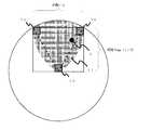
図1は、本発明の実施の形態1に係る測位システムの基地局配置を示すものである。
図1において、1a〜1cは無線基地局、2は被測位端末である。
無線基地局1a〜1cは、正三角形状に配置される。ビルなどの大きなエリアに配置する際には、横の長さ1に対して縦の長さがsin(π/3)となるような四角形のエリアに区切りながら、距離1側の隣り合う角2ヶ所と、相対する辺の中央1ヶ所とに無線基地局を配置する。
FIG. 1 shows a base station arrangement of a positioning system according to
In FIG. 1, 1a to 1c are radio base stations, and 2 is a terminal to be measured.
The radio base stations 1a to 1c are arranged in a regular triangle shape. When placing in a large area such as a building, the
なお、正三角形の各辺は、各無線基地局1a〜1cの最大通信距離と等しくする。
例えば、基地局の最大通信距離を10mとした場合には、横10m、縦8.7mの四角形をつくりながら、10mの辺の隣り合う角と、相対する辺の中央とに無線基地局を配置していくことになる。Each side of the equilateral triangle is set equal to the maximum communication distance of each of the radio base stations 1a to 1c.
For example, if the maximum communication distance of the base station is 10 m, a radio base station is placed at the corner adjacent to the 10 m side and the center of the opposite side while creating a 10 m wide and 8.7 m long square. Will do.
無線基地局の通信可能距離と、無線基地局間の距離を等しくすることにより、無線基地局1cの通信可能なエリアを円で描いた場合、図1に示すような円が描かれる。
それぞれの無線基地局から、半径が通信可能距離に等しい円を描き、その円が重なる領域(図1の網掛けのエリア11)が、3つの無線基地局全てが通信可能なエリア11となる。
このエリア11内に被測位端末2が配置されていれば、正確に被測位端末2の位置を求めることが可能となる。When the communicable distance of the radio base station and the distance between the radio base stations are equalized, when the communicable area of the radio base station 1c is drawn in a circle, a circle as shown in FIG. 1 is drawn.
A circle whose radius is equal to the communicable distance is drawn from each radio base station, and an area where the circles overlap (shaded area 11 in FIG. 1) is an area 11 in which all three radio base stations can communicate.
If the measured
無線基地局1a〜1cそれぞれから被測位端末2までの距離は、例えば上記特許文献1に開示された方法等により求めることが可能である。したがって、無線基地局1a〜1cの位置が定められていれば、3つの無線基地局からの距離をもとに、被測位端末2の相対位置を求めることが可能となる。 The distance from each of the radio base stations 1a to 1c to the
なお、各無線基地局1a〜1cの通信方式等の仕様は、設置環境等に応じて適宜定めるものとする。
また、無線基地局からの距離をもとに被測位端末2の位置を計算する処理は、各無線基地局が自ら行ってもよいし、別の演算装置等に処理を委譲してもよい。It should be noted that the specifications such as the communication method of each of the radio base stations 1a to 1c are appropriately determined according to the installation environment and the like.
Further, the process of calculating the position of the
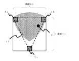
図2は、通信範囲外にある被測位端末2の位置を推定する例を説明するものである。
図2において、無線基地局1bと無線基地局1cからの測位信号により、被測位端末の位置は、2の位置と2’の位置の2ヶ所いずれかであると推定されたものとする。
このとき、無線基地局1aから被測位端末2に対して通信し、通信不可能だった場合には、被測位端末の位置は、無線基地局1aの通信範囲外である2’の位置であると推定することが可能である。FIG. 2 illustrates an example of estimating the position of the measured
In FIG. 2, it is assumed that the position of the terminal to be measured is estimated to be one of two positions, that is, the position of 2 and the position of 2 ′, based on positioning signals from the radio base station 1b and the radio base station 1c.
At this time, when communication is made from the radio base station 1a to the measured
図3は、被測位端末2の位置推定が可能なエリアを示すものである。
図2で説明した事項を勘案すると、被測位端末2の位置は、図1で説明したエリア11よりも広いエリアにおいて、推定が可能であることが分かる。即ち、無線基地局1a〜1cのうちいずれか2つの無線基地局が通信可能なエリアであれば、被測位端末2の位置推定が可能である。
したがって、図3に網掛けで示したエリアが、被測位端末2の位置推定可能な範囲となる。FIG. 3 shows an area where the position of the measured
Considering the matters described in FIG. 2, it can be understood that the position of the
Therefore, the area shown by shading in FIG. 3 is a range in which the position of the
以上のように、本実施の形態1によれば、無線基地局1a〜1cを正三角形状に配置するとともに、正三角形の各辺が無線基地局の通信可能距離と等しくなるように配置することにより、3つの無線基地局で、位置特定可能な範囲を大きくすることが可能となる。また、被測位端末2の位置特定の精度を高くすることが可能となる。 As described above, according to the first embodiment, radio base stations 1a to 1c are arranged in an equilateral triangle, and each side of the equilateral triangle is arranged to be equal to the communicable distance of the radio base station. Accordingly, it is possible to increase the range in which the position can be specified by the three wireless base stations. In addition, it is possible to increase the accuracy of specifying the position of the
また、本実施の形態1によれば、図2〜図3で説明したように、無線基地局1a〜1cのうちいずれか2つの基地局の通信範囲内にある被測位端末2の位置を推定することが可能であり、位置推定の範囲を大きくすることができる。 Moreover, according to this
実施の形態2.
図4は、本発明の実施の形態2に係る測位システムの基地局配置を示すものである。
各無線基地局1a〜1cは、二等辺三角形状に配置される。また、その二等辺三角形の高さと底辺の長さは、各無線基地局1a〜1cの最大通信距離と等しくする。
したがって、各無線基地局1a〜1cは、無線基地局の最大通信距離を1辺の長さとする正方形で区切られたエリアに対して隣り合う角に2つの無線基地局が位置し、相対する辺の中央に別の無線基地局が位置するように配置される。
FIG. 4 shows the base station arrangement of the positioning system according to
Each of the radio base stations 1a to 1c is arranged in an isosceles triangle shape. The height of the isosceles triangle and the length of the base are made equal to the maximum communication distance of each of the radio base stations 1a to 1c.
Accordingly, each of the radio base stations 1a to 1c has two radio base stations located at corners adjacent to an area divided by a square having the maximum communication distance of the radio base station as one side, and opposing sides. Is arranged such that another radio base station is located in the center of the network.
なお、被測位端末2の位置特定が可能なエリア11は、図4の網掛けした領域となり、実施の形態1の図1で説明したエリア11より若干小さくなるが、ビルなどの大きなエリアに無線基地局を配置する際の設置工事のように、エリアを区切る必要がある場合に、正四角形状にエリアを区切ればよいため、施工が簡単となるメリットがある。
また、無線基地局1a〜1cの距離は、実施の形態1とほぼ同様であり、被測位端末2の位置特定能力も実施の形態1に近いレベルで保たれている。Note that the area 11 where the position of the
Further, the distances between the radio base stations 1a to 1c are substantially the same as those in the first embodiment, and the position identification capability of the
実施の形態3.
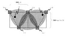
図5は、本発明の実施の形態3に係る測位システムの基地局配置を示すものである。
図5において、無線基地局1a〜1eは、3つの正三角形を形成するように連続的に配置されている。
また、正三角形の各辺は、各無線基地局1a〜1eの最大通信距離と等しくなるように配置され、正三角形の辺は、他の正三角形のいずれかの辺と重なり合っている。
図5において、被測位端末2の位置特定が可能なエリアは、同図の網掛けがされているエリアとなる。
FIG. 5 shows the base station arrangement of the positioning system according to
In FIG. 5, the radio base stations 1a to 1e are continuously arranged so as to form three equilateral triangles.
Further, each side of the equilateral triangle is arranged to be equal to the maximum communication distance of each of the radio base stations 1a to 1e, and the side of the equilateral triangle overlaps with any side of other equilateral triangles.
In FIG. 5, the area where the position of the measured
図5のような無線基地局の配置により、図1の配置と比較してさらに広範なエリアで、被測位端末2の位置を精度高く推定することができる。
なお、図5では5つの無線基地局1a〜1eの配置を示したが、無線基地局の数は5個に限られず、さらに多くの無線基地局を配置してもよい。With the arrangement of the radio base stations as shown in FIG. 5, the position of the
5 shows the arrangement of five radio base stations 1a to 1e, the number of radio base stations is not limited to five, and more radio base stations may be arranged.
実施の形態4.
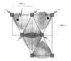
図6は、本発明の実施の形態4に係る測位システムの基地局配置を示すものである。
図6において、無線基地局1a〜1eは、3つの二等辺三角形を形成するように連続的に配置されている。
また、二等辺三角形の高さと底辺の長さは、各無線基地局1a〜1eの最大通信距離と等しくなるように配置され、二等辺三角形の斜辺と底辺は、それぞれ他の二等辺三角形の斜辺と底辺に重なり合っている。
図6において、被測位端末2の位置特定が可能なエリアは、同図の網掛けがされているエリアとなる。
FIG. 6 shows the base station arrangement of the positioning system according to
In FIG. 6, the radio base stations 1a to 1e are continuously arranged so as to form three isosceles triangles.
Further, the height of the isosceles triangle and the length of the base are arranged to be equal to the maximum communication distance of each of the radio base stations 1a to 1e, and the hypotenuse and base of the isosceles triangle are the hypotenuses of other isosceles triangles, respectively. And overlaps the bottom.
In FIG. 6, the area where the position of the measured
図6のような無線基地局の配置により、図4の配置と比較してさらに広範なエリアで、被測位端末2の位置を精度高く推定することができる。
なお、本実施の形態4では5つの無線基地局1a〜1eの配置を説明したが、無線基地局の数は5個に限られず、図6に示すようにさらに多くの無線基地局を配置してもよい。With the arrangement of the radio base stations as shown in FIG. 6, the position of the
In the fourth embodiment, the arrangement of five radio base stations 1a to 1e has been described. However, the number of radio base stations is not limited to five, and more radio base stations are arranged as shown in FIG. May be.
実施の形態3で説明した図5の配置と、本実施の形態4で説明した図6の配置を比較すると、図5の配置ではエリアを横1に対して縦sin(π/3)で複数区切っていかなければならず、無線基地局の設置工事に時間がかかってしまうのに対し、図6の配置では正四角形状にエリアを区切ればよいため、施工が簡単となるメリットがある。 Comparing the arrangement of FIG. 5 described in the third embodiment with the arrangement of FIG. 6 described in the fourth embodiment, the arrangement of FIG. While it takes a long time to install the radio base station, the arrangement shown in FIG. 6 has an advantage of simplifying the construction because the area may be divided into a regular square shape.
また、図5の配置と比較すると、被測位端末2の位置特定可能エリアが若干小さくなるが、無線基地局1a〜1eの距離は、実施の形態3とほぼ同様であり、被測位端末2の位置特定能力も実施の形態3に近いレベルで保たれている。 In addition, compared with the arrangement of FIG. 5, the position identifiable area of the measured
実施の形態5.
図7は、本発明の実施の形態5に係る空調システムの構成図である。
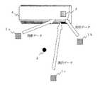
図7において、無線基地局1a〜1c、被測位端末2については、実施の形態1〜4で説明したものと同様であるため、説明を省略する。無線基地局1a〜1cの配置は、実施の形態1〜4で説明したものでもよいし、その他、被測位端末2の位置特定が可能な配置を用いてもよい。
空調機4は、無線基地局1a〜1cと無線通信が可能な無線通信部3を備える。
FIG. 7 is a configuration diagram of an air conditioning system according to
In FIG. 7, the radio base stations 1 a to 1 c and the measured
The
無線基地局1a〜1cは、それぞれが被測位端末2までの距離を測定し、その測距データを無線通信部3に送信する。
無線通信部3は、無線基地局1a〜1cが送信した測距データを受信し、空調機4が内部に備えるCPUやマイコン等の演算部に引き渡す。
演算部は、受信した測距データと、各無線基地局1a〜1cの位置情報とをもとに、被測位端末2の位置を計算する。
次に、演算部は、計算した被測位端末2の位置に合わせて、風向を調節するように空調機の各動作部の制御を行う。これにより、スポット空調の機能を実現することができる。Each of the radio base stations 1 a to 1 c measures the distance to the
The
The calculation unit calculates the position of the
Next, the calculation unit controls each operation unit of the air conditioner so as to adjust the wind direction in accordance with the calculated position of the measured
なお、無線通信部3の通信方式等は、無線基地局1a〜1cの仕様等に応じて適宜定めるものとする。 The communication method of the
以上のように、本実施の形態5によれば、無線基地局1a〜1cが送信する測距データに基づき被測位端末2の位置を計算し、その位置に空調機4の風向を自動的に調節する、スポット空調が実現できる。
これにより、例えば被測位端末2を所持しているユーザの方へ向けて自動的に風向を調節する、といった機能の実現が可能となる。As described above, according to the fifth embodiment, the position of the
Thereby, for example, it is possible to realize a function of automatically adjusting the wind direction toward the user having the
実施の形態6.
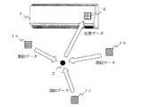
図8は、本発明の実施の形態6に係る空調システムの構成図である。
図8において、無線基地局1a〜1cは、それぞれが被測位端末2までの距離を測定する。無線基地局1aと1cは、その測距データを無線基地局1bに送信する。
無線基地局1bは、各測距データと、各無線基地局1a〜1cの位置情報とに基づき被測位端末2の位置を計算し、その位置データを無線通信部3に送信する。
以後、実施の形態5と同様に、空調機4はスポット空調機能を提供する。
その他の構成等については、実施の形態5と同様である。
FIG. 8 is a configuration diagram of an air conditioning system according to
In FIG. 8, each of the radio base stations 1 a to 1 c measures the distance to the measured
The radio base station 1b calculates the position of the
Thereafter, as in the fifth embodiment, the
Other configurations are the same as those in the fifth embodiment.
なお、図8では無線基地局1bが被測位端末2の位置を計算することとしたが、これに限られるものではなく、いずれの無線基地局が計算するかは適宜定めればよい。 In FIG. 8, the radio base station 1b calculates the position of the
以上のように、本実施の形態6によれば、無線基地局1bが被測位端末2の位置を計算するので、空調機4の演算部の計算負荷が低減され、実施の形態5と比較して空調機4をより安価に構成することができる。 As described above, according to the sixth embodiment, since the radio base station 1b calculates the position of the
実施の形態7.
図9は、本発明の実施の形態7に係る空調システムの構成図である。
図9において、無線基地局1a〜1cは、それぞれが被測位端末2までの距離を測定し、その測距データを被測位端末2に送信する。
被測位端末2は、各測距データと、各無線基地局1a〜1cの位置情報とに基づき被測位端末2の位置を計算し、その位置データを無線通信部3に送信する。
以後、実施の形態5と同様に、空調機4はスポット空調機能を提供する。
その他の構成等については、実施の形態5と同様である。
FIG. 9 is a configuration diagram of an air conditioning system according to
In FIG. 9, each of the radio base stations 1 a to 1 c measures the distance to the measured
The measured
Thereafter, as in the fifth embodiment, the
Other configurations are the same as those in the fifth embodiment.
以上のように、本実施の形態7によれば、被測位端末2が自己の位置を計算するので、空調機4の演算部の計算負荷が低減され、実施の形態5と比較して空調機4をより安価に構成することができる。
また、実施の形態6と異なり、各無線基地局の仕様を同一にできるので、各無線基地局の配置について、無線通信部3との距離や位置などを考慮する必要がなく、設置工事等の簡易の観点から有利である。As described above, according to the seventh embodiment, since the measured
Also, unlike the sixth embodiment, the specifications of each radio base station can be made the same, so there is no need to consider the distance and position with the
実施の形態8.
実施の形態5〜7では、被測位端末2の位置を計算し、風向を自動的に調節することを説明したが、空調機の制御において、風向調節の他にも、冷暖房のモードや風の強さ、湿度などを制御することが考えられる。
本発明の実施の形態8では、かかる風向調節以外の制御について説明する。
なお、各機器の構成は実施の形態5〜7で説明したものとほぼ同様であるため、本実施の形態8では、これらと異なる構成を中心に説明する。Embodiment 8 FIG.
In
In Embodiment 8 of the present invention, control other than such wind direction adjustment will be described.
Since the configuration of each device is substantially the same as that described in the fifth to seventh embodiments, this eighth embodiment will be described with a focus on a configuration different from these.
本実施の形態8において、ユーザは被測位端末2を操作して空調機4の温度や風の強さ等を設定し、これらの制御情報を送信するものとする。
以下の説明では、説明の簡易の観点から、空調機の制御対象として設定温度のみを取り上げ、温度制御を行う構成と動作例について説明する。In the eighth embodiment, it is assumed that the user operates the measured
In the following description, from the viewpoint of simplicity of explanation, only the set temperature is taken as a control target of the air conditioner, and a configuration and an operation example for performing temperature control will be described.
まず、被測位端末2より空調機4の制御情報を送信する構成について説明する。
被測位端末2は、空調機4に対する制御情報(冷暖房のモードや風の強さなどの指示)を空調機4に送信する。空調機4は、被測位端末2の位置に向けて、その制御情報の内容に即した空調動作を行う。First, the structure which transmits the control information of the
The measured
制御情報の送信は、被測位端末2より空調機4(無線通信部3)へ直接送信してもよいし、無線基地局1a〜1cいずれかを介して送信してもよい。このとき、測距データや位置データの送受信に用いる通信方式や通信手段を用いるようにすれば、制御情報の送受信のために新たな通信部を設けなくてよいので、便宜である。
いずれの通信方式や通信手段を用いるかは、実施の形態5〜7で説明した各機器の構成等に応じて適切に選択すればよい。The control information may be transmitted directly from the measured
Which communication method or communication means is used may be appropriately selected according to the configuration of each device described in the fifth to seventh embodiments.
次に、被測位端末2の位置における温度を調節する構成について説明する。これには、下記(1)〜(2)の2種類の構成が考えられる。
(1)空調機4が温度センサを備えている構成
(2)被測位端末2が温度センサを備えている構成Next, the structure which adjusts the temperature in the position of the to-
(1) Configuration in which the
(1)空調機4が温度センサを備えている構成
空調機4が、ムービング機能(方向を制御できる機能)を備えた赤外線温度センサ等の温度センサを備えている場合には、被測位端末2の位置に向けてスポット温度調節機能を提供することができる。
まず、実施の形態5〜7で説明した手法により被測位端末2の位置を計算する。
次に、被測位端末2は、空調機4に制御情報として設定温度指示データを送信する。
空調機4は、上述の温度センサで被測位端末2の位置の温度を測定し、同位置が設定温度になるように各動作部を制御して、温度調節を行う。各動作部の制御手法は、公知の技術を用いることができる。(1) Configuration in which the
First, the position of the
Next, the measured
The
(2)被測位端末2が温度センサを備えている構成
被測位端末2が温度センサを備えている場合でも、同様に被測位端末2の位置に向けてスポット温度調節機能を提供することができる。
まず、実施の形態5〜7で説明した手法により被測位端末2の位置を計算する。
次に、被測位端末2は、空調機4に制御情報として設定温度指示データを送信する。
また、被測位端末2は、温度センサの測定結果を定期的に空調機4に送信する。
空調機4は、被測位端末2から受信した設定温度指示と、温度センサの測定結果との差異から、被測位端末2の位置が設定温度になるように各動作部を制御して、温度調節を行う。各動作部の制御手法は、公知の技術を用いることができる。(2) Configuration in which the measured
First, the position of the
Next, the measured
In addition, the measured
The
なお、上述の(1)〜(2)において、被測位端末2より設定温度指示データや温度測定結果を送信する際には、被測位端末2より空調機4(無線通信部3)へ直接送信してもよいし、無線基地局1a〜1cいずれかを介して送信してもよい。
いずれの通信方式や通信手段を用いるかは、実施の形態5〜7で説明した各機器の構成等に応じて適切に選択すればよい。In the above (1) to (2), when the set temperature instruction data and the temperature measurement result are transmitted from the measured
Which communication method or communication means is used may be appropriately selected according to the configuration of each device described in the fifth to seventh embodiments.
また、本実施の形態8において、被測位端末2から制御情報を送信することを説明したが、制御情報を別の手段で空調機4に送信し、その制御情報の内容に即した空調動作を、被測位端末2の位置に提供するように構成してもよい。 Further, in the eighth embodiment, it has been described that the control information is transmitted from the terminal to be measured 2, but the control information is transmitted to the
また、上記では温度センサの例についてのみ説明したが、その他の物理量を測定するセンサ、例えば湿度センサなどの測定結果に基づき空調機を制御し、被測位端末2の位置の湿度を調節するように構成することも可能である。 Moreover, although only the example of the temperature sensor has been described above, the air conditioner is controlled based on the measurement result of a sensor that measures other physical quantities, such as a humidity sensor, and the humidity at the position of the
以上のように、本実施の形態8によれば、無線基地局1a〜1cの測距データに基づき被測位端末2の位置を計算し、ユーザが指定した制御情報に基づき、同位置に向けて制御情報の内容に即した空調動作を提供することができる。 As described above, according to the eighth embodiment, the position of the
また、本実施の形態8において、空調機4が温度センサを備えた構成では、被測位端末2の位置に向けてスポット温度調節機能を提供することができる。 In the eighth embodiment, in the configuration in which the
また、本実施の形態8において、被測位端末2が温度センサを備えた構成でも、同様に被測位端末2の位置に向けてスポット温度調節機能を提供することができる。さらには、空調機4に温度センサを設ける必要がないので、空調機4をより安価に構成することができる。 Further, in the eighth embodiment, even if the measured
実施の形態9.
図10は、本発明の実施の形態9に係る照明システムの構成図である。
図10において、無線基地局1a〜1c、被測位端末2については、実施の形態5で説明したものと同様であるため、説明を省略する。無線基地局1a〜1cの配置は、実施の形態1〜4で説明したものでもよいし、その他、被測位端末2の位置特定が可能な配置を用いてもよい。
照明器具5は、無線基地局1a〜1cと無線通信が可能な無線通信部3を備える。Embodiment 9 FIG.
FIG. 10 is a configuration diagram of an illumination system according to Embodiment 9 of the present invention.
In FIG. 10, the radio base stations 1a to 1c and the measured
The
また、照明器具5は、管理エリア12を設定する手段を備える。
管理エリア12は、このエリア内に被測位端末2が入った際に照明器具5を点灯させることを指定したものである。
管理エリア12の設定は、照明器具5が備えるスイッチ等で行ってもよいし、フラッシュメモリ等のメモリ装置で管理エリア12の設定データを授受してもよく、また任意の通信手段により設定するように構成してもよい。The
The management area 12 specifies that the
The setting of the management area 12 may be performed by a switch or the like provided in the
無線基地局1a〜1cは、それぞれが被測位端末2までの距離を測定し、その測距データを無線通信部3に送信する。
無線通信部3は、無線基地局1a〜1cが送信した測距データを受信し、照明器具5が内部に備えるCPUやマイコン等の演算部に引き渡す。
演算部は、受信した測距データと、各無線基地局1a〜1cの位置情報とをもとに、被測位端末2の位置を計算する。
次に、演算部は、計算した被測位端末2の位置が管理エリア12内にあるか否かを判定し、被測位端末2が管理エリア12内に入ったと判定すると、照明器具5を点灯させるように各動作部を制御する。Each of the radio base stations 1 a to 1 c measures the distance to the
The
The calculation unit calculates the position of the
Next, the computing unit determines whether or not the calculated position of the measured
なお、無線通信部3の通信方式等は、無線基地局1a〜1cの仕様等に応じて適宜定めるものとする。 The communication method of the
照明器具5が、照明の光線照射方向を変更する、照明器具5自体を回転させる等の手段によって照明の方向を変更することができる手段を備えている場合は、被測位端末2の位置に自動的に照明を向けるように構成することもできる。
このような被測位端末2の位置に追従した照明動作は、管理エリア12の範囲内でのみ行うようにしてもよいし、被測位端末2の位置特定が可能なエリア内の全てで行うようにしてもよい。When the
Such an illumination operation following the position of the measured
以上のように、本実施の形態9によれば、無線基地局1a〜1cが送信する測距データに基づき被測位端末2の位置を計算し、管理エリア12内に被測位端末2が入ったときに自動的に照明器具5を点灯させることができる。
このような測位機能を備えた照明システムを用いることにより、照明器具5の検知エリアを自在に設定することができるため、従来の赤外線で人を検知する方式と比較すると、赤外線を遮る壁があったとしても、事前に照明器具5を点灯させることができる。
これにより、例えば、部屋のドアを開ける前に部屋の明かりを点灯する、といった機能を実現することが可能となる。As described above, according to the ninth embodiment, the position of the
By using an illumination system having such a positioning function, the detection area of the
Thereby, for example, it is possible to realize a function of lighting a room light before opening the door of the room.
実施の形態10.
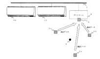
図11は、本発明の実施の形態10に係る照明システムの構成図である。
図11において、無線基地局1a〜1cは、それぞれが被測位端末2までの距離を測定する。無線基地局1aと1cは、その測距データを無線基地局1bに送信する。
無線基地局1bは、各測距データと、各無線基地局1a〜1cの位置情報とに基づき被測位端末2の位置を計算し、その位置データを無線通信部3に送信する。
以後、実施の形態9と同様に、照明器具5は照明を提供する。
その他の構成等については、実施の形態9と同様である。Embodiment 10 FIG.
FIG. 11 is a block diagram of an illumination system according to Embodiment 10 of the present invention.
In FIG. 11, each of the radio base stations 1 a to 1 c measures the distance to the measured
The radio base station 1b calculates the position of the
Thereafter, as in the ninth embodiment, the
Other configurations are the same as those in the ninth embodiment.
なお、図11では無線基地局1bが被測位端末2の位置を計算することとしたが、これに限られるものではなく、いずれの無線基地局が計算するかは適宜定めればよい。 In FIG. 11, the radio base station 1b calculates the position of the
以上のように、本実施の形態10によれば、無線基地局1bが被測位端末2の位置を計算するので、照明器具5の演算部の計算負荷が低減され、実施の形態9と比較して照明器具5をより安価に構成することができる。 As described above, according to the tenth embodiment, since the radio base station 1b calculates the position of the
実施の形態11.
図12は、本発明の実施の形態11に係る照明システムの構成図である。
図12において、無線基地局1a〜1cは、それぞれが被測位端末2までの距離を測定し、その測距データを被測位端末2に送信する。
被測位端末2は、各測距データと、各無線基地局1a〜1cの位置情報とに基づき被測位端末2の位置を計算し、その位置データを無線通信部3に送信する。
以後、実施の形態9と同様に、照明器具5は照明を提供する。
その他の構成等については、実施の形態9と同様である。Embodiment 11 FIG.
FIG. 12 is a configuration diagram of an illumination system according to Embodiment 11 of the present invention.
In FIG. 12, each of the radio base stations 1 a to 1 c measures the distance to the measured
The measured
Thereafter, as in the ninth embodiment, the
Other configurations are the same as those in the ninth embodiment.
以上のように、本実施の形態11によれば、被測位端末2が自己の位置を計算するので、照明器具5の演算部の計算負荷が低減され、実施の形態9と比較して照明器具5をより安価に構成することができる。
また、実施の形態9と異なり、各無線基地局の仕様を同一にできるので、各無線基地局の配置について、無線通信部3との距離や位置などを考慮する必要がなく、設置工事等の簡易の観点から有利である。As described above, according to the eleventh embodiment, since the measured
In addition, unlike the ninth embodiment, the specifications of each radio base station can be made the same, so there is no need to consider the distance or position of the
実施の形態12.
実施の形態9〜11では、被測位端末2の位置を計算し、照明方向を自動的に調節することを説明したが、照明器具の制御において、照明方向調節の他にも、照度の設定値などを制御することが考えられる。
本発明の実施の形態12では、かかる照明方向調節以外の制御について説明する。
なお、各機器の構成は実施の形態9〜11で説明したものとほぼ同様であるため、本実施の形態12では、これらと異なる構成を中心に説明する。Embodiment 12 FIG.
In the ninth to eleventh embodiments, it has been described that the position of the
In Embodiment 12 of the present invention, control other than the illumination direction adjustment will be described.
Since the configuration of each device is substantially the same as that described in the ninth to eleventh embodiments, the configuration different from these will be mainly described in the twelfth embodiment.
まず、被測位端末2より照明器具5の制御情報を送信する構成について説明する。
被測位端末2は、照明器具5に対する制御情報(照度の設定値などの指示)を照明器具5に送信する。照明器具5は、被測位端末2の位置に向けて、その制御情報の内容に即した照明動作を行う。First, the structure which transmits the control information of the
The measured
制御情報の送信は、被測位端末2より照明器具5(無線通信部3)へ直接送信してもよいし、無線基地局1a〜1cいずれかを介して送信してもよい。このとき、測距データや位置データの送受信に用いる通信方式や通信手段を用いるようにすれば、制御情報の送受信のために新たな通信部を設けなくてよいので、便宜である。
いずれの通信方式や通信手段を用いるかは、実施の形態9〜11で説明した各機器の構成等に応じて適切に選択すればよい。The control information may be transmitted directly from the terminal to be measured 2 to the lighting fixture 5 (wireless communication unit 3), or may be transmitted via any one of the wireless base stations 1a to 1c. At this time, if a communication method or communication means used for transmission / reception of distance measurement data or position data is used, it is convenient because a new communication unit does not have to be provided for transmission / reception of control information.
Which communication method or communication means is used may be appropriately selected according to the configuration of each device described in the ninth to eleventh embodiments.
次に、被測位端末2の位置における照度を調節する構成について説明する。これには、下記(1)〜(2)の2種類の構成が考えられる。それぞれの場合における制御情報の送受信などの動作は、実施の形態8で説明した空調機の制御と同様であるため、説明を省略する。
(1)照明器具5が照度センサを備えている構成
(2)被測位端末2が照度センサを備えている構成Next, the structure which adjusts the illumination intensity in the position of the to-
(1) Configuration in which the
なお、上述の(1)〜(2)において、被測位端末2より設定照度指示データや照度測定結果を送信する際には、被測位端末2より照明器具5(無線通信部3)へ直接送信してもよいし、無線基地局1a〜1cいずれかを介して送信してもよい。
いずれの通信方式や通信手段を用いるかは、実施の形態9〜11で説明した各機器の構成等に応じて適切に選択すればよい。In the above (1) to (2), when transmitting the set illuminance instruction data and the illuminance measurement result from the measured
Which communication method or communication means is used may be appropriately selected according to the configuration of each device described in the ninth to eleventh embodiments.
また、本実施の形態12において、被測位端末2から制御情報を送信することを説明したが、制御情報を別の手段で照明器具5に送信し、その制御情報の内容に即した照明動作を、被測位端末2の位置に提供するように構成してもよい。 Further, in the twelfth embodiment, it has been described that the control information is transmitted from the measured
以上のように、本実施の形態12によれば、無線基地局1a〜1cの測距データに基づき被測位端末2の位置を計算し、ユーザが指定した制御情報に基づき、同位置に向けて制御情報の内容に即した照明動作を提供することができる。 As described above, according to the twelfth embodiment, the position of the
また、本実施の形態12において、照明器具5が照度センサを備えた構成では、被測位端末2の位置に向けて照度調節機能を提供することができる。 In the twelfth embodiment, in the configuration in which the
また、本実施の形態12において、被測位端末2が照度センサを備えた構成でも、同様に被測位端末2の位置に向けて照度調節機能を提供することができる。さらには、照明器具5に照度センサを設ける必要がないので、照明器具5をより安価に構成することができる。 Further, in the twelfth embodiment, even when the measured
実施の形態13.
本発明の実施の形態13では、ゲートウェイ装置を備えた空調システムについて説明する。ゲートウェイ装置は、空調用ネットワークに接続され、同ネットワークを介して空調機を遠隔制御するなどの目的で設けられる機器である。
以下、被測位端末2の位置を特定し、ゲートウェイ装置より空調機の動作制御を行う構成について説明する。Embodiment 13 FIG.
In the thirteenth embodiment of the present invention, an air conditioning system including a gateway device will be described. The gateway device is a device that is connected to an air conditioning network and is provided for the purpose of remotely controlling the air conditioner via the network.
Hereinafter, the structure which specifies the position of the to-
図13は、本実施の形態13に係る空調システムの構成図である。
図13において、無線基地局1a〜1c、無線通信部3は、実施の形態5で説明したものと同様の機能を備える。
無線基地局1a〜1cの配置は、実施の形態1〜4で説明したものでもよいし、その他、被測位端末2の位置特定が可能な配置を用いてもよい。
ゲートウェイ6は、空調用ネットワーク7に接続されており、同ネットワークに接続されている空調機4a〜4bの動作を制御する。ゲートウェイ6は、無線通信部3を備えており、無線基地局1a〜1cと無線通信が可能である。また、被測位端末2の位置を計算するCPUやマイコン等の演算部を備える。
空調機4a〜4b、ゲートウェイ6は、空調用ネットワーク7を介して通信可能なインターフェースを適宜備える。通信方式は、適切なものを適宜用いる。FIG. 13 is a configuration diagram of an air conditioning system according to the thirteenth embodiment.
In FIG. 13, the radio base stations 1 a to 1 c and the
The arrangement of the radio base stations 1a to 1c may be the one described in the first to fourth embodiments, or an arrangement that can identify the position of the
The
The
次に、図13の構成の下で、ゲートウェイ6が空調機4a〜4bの動作を制御する手順について説明する。制御手順は概ね実施の形態5と同様であるが、ゲートウェイ6が制御を行う点、空調機が複数存在する点、などが実施の形態5と異なる。 Next, a procedure for the
無線基地局1a〜1cは、それぞれが被測位端末2までの距離を測定し、その測距データを無線通信部3に送信する。
無線通信部3は、無線基地局1a〜1cが送信した測距データを受信し、ゲートウェイ6が内部に備える演算部に引き渡す。
演算部は、受信した測距データと、各無線基地局1a〜1cの位置情報とをもとに、被測位端末2の位置を計算する。
次に、ゲートウェイ6は、演算部が求めた被測位端末2の位置に風向を調節するよう、空調機4a〜4bを制御する。Each of the radio base stations 1 a to 1 c measures the distance to the
The
The calculation unit calculates the position of the
Next, the
ゲートウェイ6による空調機4a〜4bの制御動作の例についてより詳しく述べると、例えば以下のようになる。
(1)各空調機の位置は、ゲートウェイ6が備える記憶装置にあらかじめ記憶させておく。
(2)次に、ゲートウェイ6は、その空調機の風向を被測位端末2に向けて調節する。
(3)ゲートウェイ6は、まず被測位端末2の位置に最も近い空調機を特定する。An example of the control operation of the
(1) The position of each air conditioner is stored in advance in a storage device provided in the
(2) Next, the
(3) The
上記(1)〜(3)は制御動作の一例であり、必ずしも被測位端末2の位置に最も近い空調機を制御する必要はなく、被測位端末2や空調機4a〜4bの位置関係に応じて適切な制御を行えばよい。 The above (1) to (3) are examples of the control operation, and it is not always necessary to control the air conditioner closest to the position of the measured
なお、空調機4a〜4bに、別の被測位端末を設置ないし内蔵した場合は、各空調機の位置を無線基地局で測位することができるため、ゲートウェイ6に各空調機の位置をあらかじめ格納させておく必要はない。
この被測位端末は、本実施の形態13における「第2被測位端末」に相当する。In addition, when another positioning terminal is installed in or built in the
This measured terminal corresponds to the “second measured terminal” in the thirteenth embodiment.
また、本実施の形態13では、空調用ネットワーク7に空調機が2つ接続されている構成について説明したが、空調機の台数はこれに限られるものではない。以下の実施の形態についても同様である。 In the thirteenth embodiment, the configuration in which two air conditioners are connected to the
以上のように、本実施の形態13によれば、ゲートウェイ6は被測位端末2の位置に向けて空調機4a〜4bの動作を制御することができるので、ゲートウェイ6を介した遠隔制御や複数空調機の一括制御を実現することができる。 As described above, according to the thirteenth embodiment, the
また、空調機4a〜4bに、別の被測位端末を設置ないし内蔵することにより、各空調機の位置をゲートウェイ6に記憶させる手間が省略でき、さらには設置後にも任意に空調機の位置を変更することができるので、空調システムの構成の柔軟性が増す。 In addition, by installing or incorporating another positioning terminal in the
実施の形態14.
実施の形態13では、被測位端末2の位置を計算し、風向を自動的に調節することを説明したが、空調機の制御において、風向調節の他にも、冷暖房のモードや風の強さ、湿度などを制御することが考えられる。
本発明の実施の形態14では、かかる風向調節以外の制御について説明する。
なお、各機器の構成は実施の形態13で説明したものとほぼ同様であるため、本実施の形態14では、これらと異なる構成を中心に説明する。Embodiment 14 FIG.
In the thirteenth embodiment, it has been described that the position of the
In the fourteenth embodiment of the present invention, control other than such wind direction adjustment will be described.
The configuration of each device is substantially the same as that described in the thirteenth embodiment, and therefore, in the fourteenth embodiment, the description will focus on a configuration different from these.
本実施の形態14において、ユーザは被測位端末2を操作して温度や風の強さ等を設定し、これらの制御情報を送信するものとする。
以下の説明では、説明の簡易の観点から、空調機の制御対象として設定温度のみを取り上げ、温度制御を行う構成と動作例について説明する。In the fourteenth embodiment, it is assumed that the user operates the measured
In the following description, from the viewpoint of simplicity of explanation, only the set temperature is taken as a control target of the air conditioner, and a configuration and an operation example for performing temperature control will be described.
温度センサを設ける箇所と温度制御の動作主体に関し、例えば以下の6つの構成例が考えられる。以下、各構成例について説明する。 For example, the following six configuration examples are conceivable regarding the location where the temperature sensor is provided and the operation subject of the temperature control. Hereinafter, each configuration example will be described.
(構成例1)空調機が温度センサを備え、ゲートウェイ6が温度制御を行う。
(構成例2)空調機が温度センサを備え、ゲートウェイ6は温度設定の指示値のみを空調機に通知し、空調機が自ら温度制御を行う。
(構成例3)被測位端末2が温度センサを備え、ゲートウェイ6が温度制御を行う。
(構成例4)被測位端末2が温度センサを備え、測定結果を空調機経由でゲートウェイに送信し、ゲートウェイ6が温度制御を行う。
(構成例5)ゲートウェイ6が温度センサを備え、ゲートウェイ6が温度制御を行う。
(構成例6)ゲートウェイ6が温度センサを備え、ゲートウェイ6は温度設定の指示値と測定値を空調機に通知し、空調機が自ら温度制御を行う。(Configuration example 1) The air conditioner includes a temperature sensor, and the
(Configuration Example 2) The air conditioner includes a temperature sensor, and the
(Configuration example 3) The
(Configuration Example 4) The measured
(Configuration Example 5) The
(Configuration Example 6) The
(構成例1)について
空調機4a〜4bが、ムービング機能を備えた赤外線温度センサ等の温度センサを備えている場合には、以下のように動作制御を行う。
ゲートウェイ6は、実施の形態5〜7で説明した手法により被測位端末2の位置を計算し、その位置を空調機4a〜4bに通知する。
被測位端末2は、ゲートウェイ6に制御情報として設定温度指示データを送信する。
空調機4a〜4bは、上述の温度センサで被測位端末2の位置の温度を測定し、測定結果をゲートウェイ6に通知する。
ゲートウェイ6は、被測位端末2の位置が設定温度になるように空調機4a〜4bの各動作部を制御して、温度調節を行う。いずれの空調機を制御するかは、実施の形態13で説明したように、設置環境等に応じて適宜定める。(Configuration Example 1) When the
The
The measured
The
The
(構成例2)について
空調機4a〜4bが測定結果をゲートウェイ6に通知するところまでは(構成例1)と同様である。
ゲートウェイ6は、被測位端末2の位置を設定温度とするように、空調機4a〜4bにその設定温度を通知する。空調機4a〜4bは、自ら各動作部を制御して、温度調節を行う。いずれの空調機に設定温度を通知するかは、(構成例1)と同様である。(Configuration Example 2) The configuration is the same as (Configuration Example 1) until the
The
(構成例3)について
被測位端末2が温度センサを備えている場合には、以下のように動作制御を行う。
ゲートウェイ6は、実施の形態5〜7で説明した手法により被測位端末2の位置を計算する。
被測位端末2は、ゲートウェイ6に制御情報として設定温度指示データを送信する。
また、被測位端末2は、温度センサの測定結果を定期的にゲートウェイ6に送信する。
ゲートウェイ6は、被測位端末2から受信した設定温度指示と、温度センサの測定結果との差異から、被測位端末2の位置が設定温度になるように空調機4a〜4bの各動作部を制御して、温度調節を行う。いずれの空調機を制御するかは、(構成例1)と同様である。(Configuration Example 3) When the measured
The
The measured
Further, the measured
The
(構成例4)について
ゲートウェイ6は、実施の形態5〜7で説明した手法により被測位端末2の位置を計算する。
被測位端末2は、ゲートウェイ6に制御情報として設定温度指示データを送信する。
また、被測位端末2は、温度センサの測定結果を定期的に空調機に送信する。
空調機は、その測定結果をゲートウェイ6に送信する。
ゲートウェイ6は、被測位端末2から受信した設定温度指示と、温度センサの測定結果との差異から、被測位端末2の位置が設定温度になるように空調機4a〜4bの各動作部を制御して、温度調節を行う。いずれの空調機を制御するかは、(構成例1)と同様である。(Configuration Example 4) The
The measured
Moreover, the to-
The air conditioner transmits the measurement result to the
The
(構成例5)について
ゲートウェイ6が、ムービング機能を備えた赤外線温度センサ等の温度センサを備えている場合には、以下のように動作制御を行う。
ゲートウェイ6は、実施の形態5〜7で説明した手法により被測位端末2の位置を計算する。
被測位端末2は、ゲートウェイ6に制御情報として設定温度指示データを送信する。
ゲートウェイ6は、上述のセンサで被測位端末2の位置の温度を測定する。
ゲートウェイ6は、被測位端末2から受信した設定温度指示と、温度センサの測定結果との差異から、被測位端末2の位置が設定温度になるように空調機4a〜4bの各動作部を制御して、温度調節を行う。いずれの空調機を制御するかは、(構成例1)と同様である。(Configuration Example 5) When the
The
The measured
The
The
(構成例6)について
ゲートウェイ6が温度を測定するところまでは(構成例5)と同様である。
ゲートウェイ6は、被測位端末2の位置を設定温度とするように、空調機4a〜4bにその設定温度と測定値を通知する。
空調機4a〜4bは、自ら各動作部を制御して、温度調節を行う。いずれの空調機に設定温度を通知するかは、(構成例1)と同様である。(Configuration Example 6) The configuration is the same as (Configuration Example 5) until the
The
The
以上の(構成例1)〜(構成例6)において、被測位端末2は、設定温度指示データをゲートウェイ6に直接送信してもよいし、空調機4aまたは4bを介して送信するように構成してもよい。
後者の場合、空調機4aまたは4bは、温度の設定値をゲートウェイ6に転送し、以後は各構成例で説明したような動作制御が行われる。In the above (Configuration Example 1) to (Configuration Example 6), the measured
In the latter case, the
本実施の形態14において、被測位端末2から制御情報を送信することを説明したが、制御情報を別の手段で送信し、その制御情報の内容に即した空調動作を、被測位端末2の位置に提供するように構成してもよい。 In the fourteenth embodiment, transmission of control information from the
また、上記では温度センサの例についてのみ説明したが、その他の物理量を測定するセンサ、例えば湿度センサなどの測定結果に基づき空調機を制御するように構成することも可能である。 Moreover, although only the example of the temperature sensor has been described above, the air conditioner may be configured to be controlled based on the measurement result of a sensor that measures other physical quantities, for example, a humidity sensor.
以上のように、本実施の形態14によれば、被測位端末2の位置の温度を測定する温度センサを設け、同位置の温度をゲートウェイ6から調節することができる。 As described above, according to the fourteenth embodiment, the temperature sensor for measuring the temperature of the position of the
また、本実施の形態14によれば、ゲートウェイ6は、温度の測定結果に基づき複数の空調機の制御を遠隔から一括して行うことができる。
例えば、被測位端末2の位置が空調機4a、空調機4bの中間地点にあり、片方の空調機で被測位端末2に設定された温度にならない場合には、両方の空調機を動作させることで、被測位端末2に設定された温度に近づけることが可能である。
この場合、各空調機の制御量は、全ての空調機について同一にしてもよいし、一部の空調機を中心として制御するようにしてもよい。Further, according to the fourteenth embodiment, the
For example, when the position of the measured
In this case, the control amount of each air conditioner may be the same for all the air conditioners, or may be controlled mainly for some air conditioners.
実施の形態15.
以上の実施の形態13〜14において、複数の被測位端末2が存在した場合には、ゲートウェイ6または空調機4にて被測位端末2が存在するエリアを識別し、ユーザが被測位端末2を用いて設定した温度情報にしたがって制御する。
なお、1つの空調機4に対し複数の被測位端末2により複数の異なる温度指示値が設定された場合には、同空調機が制御可能なエリアに存在する被測位端末2の多数決判定、または平均値をとる。
上記判定により、1つの空調機4で該当エリアの空調を行う。Embodiment 15 FIG.
In the above-described thirteenth to fourteenth embodiments, when a plurality of
When a plurality of different temperature indication values are set by a plurality of measured
By the above determination, the
実施の形態16.
以上の実施の形態13〜15において、ゲートウェイ6が被測位端末2の位置を計算することを説明したが、実施の形態6〜7で説明したように、無線基地局1a〜1cや被測位端末2にて被測位端末2の位置を計算するように構成してもよい。
この場合、各機器は実施の形態6〜7で説明したように、それぞれ必要な構成を適宜備えるものとする。Embodiment 16 FIG.
In Embodiments 13 to 15 described above, it has been described that the
In this case, as described in the sixth to seventh embodiments, each device is appropriately provided with a necessary configuration.
実施の形態17.
本発明の実施の形態17では、ゲートウェイ装置を備えた照明システムについて説明する。以下、被測位端末2の位置を特定し、ゲートウェイ装置より照明器具の動作制御を行う構成について説明する。Embodiment 17. FIG.
In Embodiment 17 of the present invention, a lighting system including a gateway device will be described. Hereinafter, the structure which specifies the position of the to-
図14において、無線基地局1a〜1c、無線通信部3は、実施の形態9で説明したものと同様の機能を備える。
無線基地局1a〜1cの配置は、実施の形態1〜4で説明したものでもよいし、その他、被測位端末2の位置特定が可能な配置を用いてもよい。
ゲートウェイ6は、照明用ネットワーク8に接続されており、同ネットワークに接続されている照明器具5a〜5bの動作を制御する。ゲートウェイ6は、無線通信部3を備えており、無線基地局1a〜1cと無線通信が可能である。また、被測位端末2の位置を計算するCPUやマイコン等の演算部を備える。
照明器具5a〜5b、ゲートウェイ6は、照明用ネットワーク8を介して通信可能なインターフェースを適宜備える。通信方式は、適切なものを適宜用いる。In FIG. 14, the radio base stations 1a to 1c and the
The arrangement of the radio base stations 1a to 1c may be the one described in the first to fourth embodiments, or an arrangement that can identify the position of the
The
The lighting fixtures 5a to 5b and the
次に、図14の構成の下で、ゲートウェイ6が照明器具5a〜5bの動作を制御する手順について説明する。制御手順は概ね実施の形態9と同様であるが、ゲートウェイ6が制御を行う点、照明器具が複数存在する点、などが実施の形態9と異なる。 Next, the procedure in which the
無線基地局1a〜1cは、それぞれが被測位端末2までの距離を測定し、その測距データを無線通信部3に送信する。
無線通信部3は、無線基地局1a〜1cが送信した測距データを受信し、ゲートウェイ6が内部に備える演算部に引き渡す。
演算部は、受信した測距データと、各無線基地局1a〜1cの位置情報とをもとに、被測位端末2の位置を計算する。
次に、ゲートウェイ6は、演算部が求めた被測位端末2の位置に照明方向を調節するよう、照明器具5a〜5bを制御する。Each of the radio base stations 1 a to 1 c measures the distance to the
The
The calculation unit calculates the position of the
Next, the
ゲートウェイ6による照明器具5a〜5bの制御動作の例についてより詳しく述べると、例えば以下のようになる。
(1)各照明器具の位置は、ゲートウェイ6が備える記憶装置にあらかじめ記憶させておく。
(2)次に、ゲートウェイ6は、その照明器具の照明方向を被測位端末2に向けて調節する。
(3)ゲートウェイ6は、まず被測位端末2の位置に最も近い照明器具を特定する。An example of the control operation of the lighting fixtures 5a to 5b by the
(1) The position of each lighting fixture is stored in advance in a storage device provided in the
(2) Next, the
(3) The
上記(1)〜(3)は制御動作の一例であり、必ずしも被測位端末2の位置に最も近い照明器具を制御する必要はなく、被測位端末2や照明器具5a〜5bの位置関係に応じて適切な制御を行えばよい。 The above (1) to (3) are examples of the control operation, and it is not always necessary to control the lighting fixture closest to the position of the measured
なお、照明器具5a〜5bに、別の被測位端末を設置ないし内蔵した場合は、各照明器具の位置を無線基地局で測位することができるため、ゲートウェイ6に各照明器具の位置をあらかじめ格納させておく必要はない。
この被測位端末は、本実施の形態17における「第2被測位端末」に相当する。In addition, when another positioning terminal is installed or built in the lighting fixtures 5a to 5b, the position of each lighting fixture can be stored in the
This measured terminal corresponds to the “second measured terminal” in the seventeenth embodiment.
また、本実施の形態17では、照明用ネットワーク8に照明器具が2つ接続されている構成について説明したが、照明器具の台数はこれに限られるものではない。以下の実施の形態についても同様である。 In the seventeenth embodiment, the configuration in which two lighting fixtures are connected to the lighting network 8 has been described. However, the number of lighting fixtures is not limited to this. The same applies to the following embodiments.
以上のように、本実施の形態17によれば、ゲートウェイ6は被測位端末2の位置に向けて照明器具5a〜5bの動作を制御することができるので、ゲートウェイ6を介した遠隔制御や複数照明器具の一括制御を実現することができる。 As described above, according to the seventeenth embodiment, the
また、照明器具5a〜5bに、別の被測位端末を設置ないし内蔵することにより、各照明器具の位置をゲートウェイ6に記憶させる手間が省略でき、さらには設置後にも任意に照明器具の位置を変更することができるので、照明システムの構成の柔軟性が増す。 Further, by installing or incorporating another measured terminal in the lighting fixtures 5a to 5b, the trouble of storing the location of each lighting fixture in the
実施の形態18.
実施の形態17では、被測位端末2の位置を計算し、照明方向を自動的に調節することを説明したが、照明器具の制御において、照明方向の調節の他にも、照度などを制御することが考えられる。
本発明の実施の形態18では、かかる照明方向の調節以外の制御について説明する。
なお、各機器の構成は実施の形態17で説明したものとほぼ同様であるため、本実施の形態18では、これらと異なる構成を中心に説明する。Embodiment 18 FIG.
In the seventeenth embodiment, it has been described that the position of the
In the eighteenth embodiment of the present invention, control other than adjustment of the illumination direction will be described.
Note that the configuration of each device is substantially the same as that described in the seventeenth embodiment, and therefore, in the eighteenth embodiment, a description will be given focusing on a configuration different from these.
本実施の形態18において、ユーザは被測位端末2を操作して照度等を設定し、これらの制御情報を送信するものとする。
以下の説明では、説明の簡易の観点から、照明器具の制御対象として照度のみを取り上げ、照度制御を行う構成と動作例について説明する。In the eighteenth embodiment, it is assumed that the user operates the measured
In the following description, from the viewpoint of easy explanation, only the illuminance is taken up as a control target of the lighting fixture, and a configuration and an operation example for performing the illuminance control will be described.
照度センサを設ける箇所と温度制御の動作主体に関し、例えば以下の6つの構成例が考えられる。以下、各構成例について説明する。 Regarding the location where the illuminance sensor is provided and the operation subject of temperature control, for example, the following six configuration examples are conceivable. Hereinafter, each configuration example will be described.
(構成例1)照明器具が照度センサを備え、ゲートウェイ6が照度制御を行う。
(構成例2)照明器具が照度センサを備え、ゲートウェイ6は照度設定の指示値のみを照明器具に通知し、照明器具が自ら照度制御を行う。
(構成例3)被測位端末2が照度センサを備え、ゲートウェイ6が照度制御を行う。
(構成例4)被測位端末2が照度センサを備え、測定結果を照明器具経由でゲートウェイに送信し、ゲートウェイ6が照度制御を行う。
(構成例5)ゲートウェイ6が照度センサを備え、ゲートウェイ6が照度制御を行う。
(構成例6)ゲートウェイ6が照度センサを備え、ゲートウェイ6は照度設定の指示値と測定値を照明器具に通知し、照明器具が自ら照度制御を行う。(Structure example 1) A lighting fixture is equipped with an illumination intensity sensor, and the
(Configuration Example 2) The lighting fixture includes an illuminance sensor, and the
(Configuration Example 3) The measured
(Configuration Example 4) The measured
(Configuration Example 5) The
(Configuration Example 6) The
(構成例1)について
照明器具5a〜5bが、ムービング機能等の測定方向を変更可能な機能を備えた照度センサを備えている場合には、以下のように動作制御を行う。
ゲートウェイ6は、実施の形態9〜11で説明した手法により被測位端末2の位置を計算し、その位置を照明器具5a〜5bに通知する。
被測位端末2は、ゲートウェイ6に制御情報として設定照度指示データを送信する。
照明器具5a〜5bは、上述の照度センサで被測位端末2の位置の照度を測定し、測定結果をゲートウェイ6に通知する。
ゲートウェイ6は、被測位端末2の位置が設定照度になるように照明器具5a〜5bの各動作部を制御して、照度調節を行う。いずれの照明器具を制御するかは、実施の形態17で説明したように、設置環境等に応じて適宜定める。About (Configuration Example 1) When the lighting fixtures 5a to 5b include an illuminance sensor having a function that can change the measurement direction, such as a moving function, operation control is performed as follows.
The
The measured
The luminaires 5a to 5b measure the illuminance at the position of the
The
(構成例2)について
照明器具5a〜5bが測定結果をゲートウェイ6に通知するところまでは(構成例1)と同様である。
ゲートウェイ6は、被測位端末2の位置を設定照度とするように、照明器具5a〜5bにその設定照度を通知する。照明器具5a〜5bは、自ら各動作部を制御して、照度調節を行う。いずれの照明器具に設定温度を通知するかは、(構成例1)と同様である。About (Configuration Example 2) The configuration is the same as (Configuration Example 1) until the lighting fixtures 5a to 5b notify the
The
(構成例3)について
被測位端末2が照度センサを備えている場合には、以下のように動作制御を行う。
ゲートウェイ6は、実施の形態9〜11で説明した手法により被測位端末2の位置を計算する。
被測位端末2は、ゲートウェイ6に制御情報として設定照度指示データを送信する。
また、被測位端末2は、照度センサの測定結果を定期的にゲートウェイ6に送信する。
ゲートウェイ6は、被測位端末2から受信した設定照度指示と、照度センサの測定結果との差異から、被測位端末2の位置が設定照度になるように照明器具5a〜5bの各動作部を制御して、照度調節を行う。いずれの照明器具を制御するかは、(構成例1)と同様である。(Configuration Example 3) When the measured
The
The measured
Further, the measured
The
(構成例4)について
ゲートウェイ6は、実施の形態9〜11で説明した手法により被測位端末2の位置を計算する。
被測位端末2は、ゲートウェイ6に制御情報として設定照度指示データを送信する。
また、被測位端末2は、照度センサの測定結果を定期的に照明器具に送信する。
照明器具は、その測定結果をゲートウェイ6に送信する。
ゲートウェイ6は、被測位端末2から受信した設定照度指示と、照度センサの測定結果との差異から、被測位端末2の位置が設定照度になるように照明器具5a〜5bの各動作部を制御して、照度調節を行う。いずれの照明器具を制御するかは、(構成例1)と同様である。(Configuration Example 4) The
The measured
Moreover, the to-
The luminaire transmits the measurement result to the
The
(構成例5)について
ゲートウェイ6が、ムービング機能等の測定方向を変更可能な機能を備えた照度センサを備えている場合には、以下のように動作制御を行う。
ゲートウェイ6は、実施の形態9〜11で説明した手法により被測位端末2の位置を計算する。
被測位端末2は、ゲートウェイ6に制御情報として設定照度指示データを送信する。
ゲートウェイ6は、上述のセンサで被測位端末2の位置の照度を測定する。
ゲートウェイ6は、被測位端末2から受信した設定照度指示と、照度センサの測定結果との差異から、被測位端末2の位置が設定照度になるように照明器具5a〜5bの各動作部を制御して、照度調節を行う。いずれの照明器具を制御するかは、(構成例1)と同様である。(Configuration Example 5) When the
The
The measured
The
The
(構成例6)について
ゲートウェイ6が照度を測定するところまでは(構成例5)と同様である。
ゲートウェイ6は、被測位端末2の位置を設定照度とするように、照明器具5a〜5bにその設定照度と測定値を通知する。
照明器具5a〜5bは、自ら各動作部を制御して、照度調節を行う。いずれの照明器具に設定温度を通知するかは、(構成例1)と同様である。(Configuration Example 6) The configuration is the same as (Configuration Example 5) until the
The
The luminaires 5a to 5b themselves control each operation unit to adjust the illuminance. Which lighting fixture is notified of the set temperature is the same as in (Configuration Example 1).
以上の(構成例1)〜(構成例6)において、被測位端末2は、設定照度指示データをゲートウェイ6に直接送信してもよいし、照明器具5aまたは5bを介して送信するように構成してもよい。
後者の場合、照明器具5aまたは5bは、照度の設定値をゲートウェイ6に転送し、以後は各構成例で説明したような動作制御が行われる。In the above (Configuration Example 1) to (Configuration Example 6), the
In the latter case, the luminaire 5a or 5b transfers the set value of illuminance to the
本実施の形態18において、被測位端末2から制御情報を送信することを説明したが、制御情報を別の手段で送信し、その制御情報の内容に即した照明動作を、被測位端末2の位置に提供するように構成してもよい。 In the eighteenth embodiment, the transmission of the control information from the
また、上記では照度センサの例についてのみ説明したが、その他の物理量を測定するセンサの測定結果に基づき照明器具を制御するように構成することも可能である。 Moreover, although only the example of the illuminance sensor has been described above, it is also possible to configure the lighting fixture to be controlled based on the measurement result of the sensor that measures other physical quantities.
以上のように、本実施の形態18によれば、被測位端末2の位置の照度を測定する照度センサを設け、同位置の照度をゲートウェイ6から調節することができる。 As described above, according to the eighteenth embodiment, the illuminance sensor that measures the illuminance at the position of the
また、本実施の形態18によれば、ゲートウェイ6は、照度の測定結果に基づき複数の空調機の制御を遠隔から一括して行うことができる。
例えば、被測位端末2の位置が照明器具5a〜5bの中間地点にあり、片方の照明器具で被測位端末2に設定された照度にならない場合には、両方の照明器具を動作させることで、被測位端末2に設定された照度に近づけることが可能である。
この場合、各照明器具の制御量は、全ての照明器具について同一にしてもよいし、一部の照明器具を中心として制御するようにしてもよい。Further, according to the eighteenth embodiment, the
For example, if the position of the measured
In this case, the control amount of each luminaire may be the same for all the luminaires, or may be controlled around a part of the luminaires.
実施の形態19.
以上の実施の形態17〜18において、複数の被測位端末2が存在した場合には、ゲートウェイ6または照明器具5にて被測位端末2が存在するエリアを識別し、ユーザが被測位端末2を用いて設定した照度情報にしたがって制御する。
なお、1つの照明器具5に対し複数の被測位端末2により複数の異なる照度指示値が設定された場合には、同照明器具が制御可能なエリアに存在する被測位端末2の多数決判定、または平均値をとる。
上記判定により、1つの照明器具5で該当エリアの照明を行う。Embodiment 19. FIG.
In the above Embodiments 17 to 18, when there are a plurality of
When a plurality of different illuminance instruction values are set by a plurality of
Based on the above determination, the corresponding area is illuminated by one
実施の形態20.
以上の実施の形態17〜19において、ゲートウェイ6が被測位端末2の位置を計算することを説明したが、実施の形態10〜11で説明したように、無線基地局1a〜1cや被測位端末2にて被測位端末2の位置を計算するように構成してもよい。
この場合、各機器は実施の形態10〜11で説明したように、それぞれ必要な構成を適宜備えるものとする。
In Embodiments 17 to 19 described above, it has been described that the
In this case, as described in each of the tenth to eleventh embodiments, each device has a necessary configuration as appropriate.
実施の形態21.
一般に、無線基地局1は、配下の無線ネットワークに参加する被測位端末2にアドレスを割り当て、各被測位端末2のアドレスを管理テーブル等で管理する。
上述の実施の形態1〜20では、被測位端末2のアドレスをどのように割り当てるか、即ちアドレス体系については、特段の言及をしていないが、被測位端末2のアドレスを、何らかの規則性をもって割り当てておくと、後の管理の観点から好ましい。
そこで、本発明の実施の形態21に係る測位システムでは、被測位端末2のアドレス割り当てを規則的に行う手法を説明する。Embodiment 21. FIG.
In general, the
In
Therefore, in the positioning system according to Embodiment 21 of the present invention, a method for regularly assigning addresses of the
被測位端末2にアドレスを割り当てる最も単純な手法としては、最初に無線基地局1の配下ネットワークに参加した被測位端末2から順番に、1ずつ増加するアドレス値を割り当てる、というものが考えられる。
しかし、このような手法の場合、被測位端末2の位置座標とアドレスが関連することなくアドレスが割り当てられるため、アドレス体系が明確でなく、また管理の観点からも必ずしも好ましくない。As the simplest method of assigning an address to the measured
However, in the case of such a method, since the address is assigned without relating the position coordinate of the
そこで、本実施の形態21において、無線基地局1は、被測位端末2の位置座標を取得すると、その座標値をそのまま当該被測位端末2のアドレス値として用い、管理テーブル等に登録することにする。進数の変換を行ったり、カンマなどの記号を除去したりする程度の改変であれば、必要に応じて行ってもよい。
このような手法を用いることにより、被測位端末2のアドレス体系が明確になり、また被測位端末2の位置座標とアドレスが関連性をもって把握されることになるので、管理の観点からも好ましい。Therefore, in the twenty-first embodiment, when the
By using such a method, the address system of the
なお、上述のようなアドレス割り当て手法を用いる場合、前提として、アドレス値の上限と座標値の上限は、ともに等しいか、もしくはアドレス値の上限の方が大きくなければならない。
座標値の上限の方が大きいと、座標値をそのままアドレス値に用いようとしたとき、設定しようとするアドレス値がアドレス空間を超えてしまうためである。
座標値の上限の方を大きくせざるを得ない場合は、ハッシュ値演算などを用いて極力アドレス空間を超えないように工夫することも可能であるが、管理の容易の観点からは、アドレス値の上限の方を大きくした方が好ましい。In the case of using the address assignment method as described above, it is assumed that the upper limit of the address value and the upper limit of the coordinate value are both equal or the upper limit of the address value is larger.
This is because if the upper limit of the coordinate value is larger, the address value to be set exceeds the address space when the coordinate value is used as the address value as it is.
If the upper limit of the coordinate value must be increased, it is possible to devise not exceeding the address space by using hash value calculation etc., but from the viewpoint of easy management, the address value It is preferable to increase the upper limit of.
無線基地局1が被測位端末2の位置座標をどのように取得するかについては、上述の実施の形態で説明したいずれかの手法を用いることができることを付言しておく。また、本実施の形態21で説明したアドレス割り当て手法を、上述の実施の形態1〜20において適用することもできる。以下の実施の形態についても同様である。 It is added that how the
実施の形態22.
図15は、本発明の実施の形態22に係る測位システムの基地局および被測位端末の配置を示すものである。図15において、2a〜2cは被測位端末である。
被測位端末2をビル内に配置する場合、配置の都合によって、図15に示すようにほぼ同一直線上にレイアウトされることがある。
この場合、無線基地局1aは、以下のようにして各被測位端末2のアドレスを定める。Embodiment 22. FIG.
FIG. 15 shows the arrangement of base stations and measured terminals in a positioning system according to Embodiment 22 of the present invention. In FIG. 15, 2a to 2c are positioning terminals.
When positioning the
In this case, the radio base station 1a determines the address of each measured
(1)無線基地局1aは、自己の位置を原点として座標軸を回転し、X軸、Y軸、Z軸のいずれかの軸からなる座標軸直線上に、すべての被測位端末2が配置されるように座標軸を定める。なお、図15では、X軸上に配置される例を示した。(1) The radio base station 1a rotates the coordinate axis with its own position as the origin, and all the measured
(2)次に、無線基地局1aは、設定した座標軸上における各被測位端末2の1次元座標値を取得して、各被測位端末2のアドレスとして設定し、管理テーブル等に登録する。図15の例では、X軸上の座標値(xa)、(xb)、(xc)、が各被測位端末のアドレスとして設定される。(2) Next, the radio base station 1a acquires the one-dimensional coordinate value of each measured
例えば、被測位端末2のもつアドレス空間が8bitであるときは、255個のアドレスを表現できる。
これを実空間の位置座標に換算すると、例えばビル内の空間を、3mの距離の分解能で区切って被測位端末2の位置を設定した場合には、255×3m=765mの1次元座標上に被測位端末2のアドレスを配置することが可能になる。For example, when the address space of the measured
When this is converted into the position coordinates of the real space, for example, when the position of the
なお、ビル内の空間を、3mの距離の分解能で区切って格子状に座標空間を設定した場合、被測位端末2の位置と、格子点の位置とが合致しない可能性もある。
このような場合は、被測位端末2の位置に最も近い格子点を、当該被測位端末2の座標として設定すればよい。以下の実施の形態についても同様である。In addition, when the space in a building is divided | segmented by the resolution of the distance of 3 m and a coordinate space is set to a grid | lattice form, the position of the to-
In such a case, the lattice point closest to the position of the measured
以上の処理により、被測位端末2の1次元座標値が、そのまま当該被測位端末2のアドレスとして設定されることになり、アドレス体系が明確になるとともに、アドレス管理も行いやすい。
なお、座標軸を回転するに際し、必ずしも無線基地局1aの位置を原点としなくともよいが、演算の簡易の観点からは、無線基地局1aの位置を原点にすると便宜である。以下の実施の形態についても同様である。Through the above processing, the one-dimensional coordinate value of the measured
When rotating the coordinate axes, the position of the radio base station 1a does not necessarily have to be the origin, but from the viewpoint of simple calculation, it is convenient to use the position of the radio base station 1a as the origin. The same applies to the following embodiments.
実施の形態23.
図16は、本発明の実施の形態23に係る測位システムの基地局および被測位端末の配置を示すものである。図16において、2a〜2cは被測位端末である。
被測位端末2をビル内に配置する場合、配置の都合によって、図16に示すようにほぼ同一平面上にレイアウトされることがある。
この場合、無線基地局1aは、以下のようにして各被測位端末2のアドレスを定める。Embodiment 23. FIG.
FIG. 16 shows the arrangement of base stations and measured terminals in the positioning system according to Embodiment 23 of the present invention. In FIG. 16, 2a to 2c are positioning terminals.
When positioning the
In this case, the radio base station 1a determines the address of each measured
(1)無線基地局1aは、自己の位置を原点として座標軸を回転し、X軸、Y軸、Z軸のいずれか2軸からなる座標軸平面上に、すべての被測位端末2が配置されるように座標軸を定める。なお、図16では、XY平面上に配置される例を示した。(1) The radio base station 1a rotates the coordinate axis with its own position as the origin, and all the
(2)次に、無線基地局1aは、設定した座標軸上における各被測位端末2の2次元座標値を取得して、各被測位端末2のアドレスとして設定し、管理テーブル等に登録する。図16の例では、XY平面上の座標値(xa,ya)、(xb,yb)、(xc,yc)、が各被測位端末のアドレスとして設定される。(2) Next, the radio base station 1a acquires the two-dimensional coordinate value of each measured
例えば、被測位端末2のもつアドレス空間が16bitであるときは、X座標とY座標にそれぞれ8bitを割り当てて、1座標軸につき255個のアドレスを表現できる。
これを実空間の位置座標に換算すると、例えばビル内の空間を、3mの距離の分解能で区切って被測位端末2の位置を設定した場合には、1辺が255×3m=765mの平面上における2次元座標上に被測位端末2のアドレスを配置することが可能になる。For example, when the address space of the measured
When this is converted into real space position coordinates, for example, when the position of the
以上の処理により、被測位端末2の2次元座標値が、そのまま当該被測位端末2のアドレスとして設定されることになり、アドレス体系が明確になるとともに、アドレス管理も行いやすい。 Through the above processing, the two-dimensional coordinate value of the
実施の形態24.
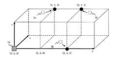
図17は、本発明の実施の形態24に係る測位システムの基地局および被測位端末の配置を示すものである。図17において、2a〜2cは被測位端末である。
無線基地局1aは、各被測位端末2の3次元座標値を取得して、各被測位端末2のアドレスとして設定し、管理テーブル等に登録する。図17の例では、座標値(xa,ya,za)、(xb,yb,zb)、(xc,yc,zc)、が各被測位端末のアドレスとして設定される。Embodiment 24. FIG.
FIG. 17 shows the arrangement of base stations and terminals to be measured in the positioning system according to Embodiment 24 of the present invention. In FIG. 17, 2a to 2c are positioning terminals.
The radio base station 1a acquires the three-dimensional coordinate value of each measured
例えば、被測位端末2のもつアドレス空間が24bitであるときは、各座標にそれぞれ8bitを割り当てて、1座標軸につき255個のアドレスを表現できる。
これを実空間の位置座標に換算すると、例えばビル内の空間を、3mの距離の分解能で区切って被測位端末2の位置を設定した場合には、1辺が255×3m=765mの立体上における3次元座標上に被測位端末2のアドレスを配置することが可能になる。For example, when the address space of the
When this is converted into the position coordinates of the real space, for example, when the position of the
以上の処理により、被測位端末2の3次元座標値が、そのまま当該被測位端末2のアドレスとして設定されることになり、アドレス体系が明確になるとともに、アドレス管理も行いやすい。 Through the above processing, the three-dimensional coordinate value of the measured
実施の形態25.
図18は、本発明の実施の形態25に係る測位システムの基地局および被測位端末の配置を示すものである。図18において、2a〜2cは被測位端末である。
実施の形態22〜24では、ビル内の空間を3mの分解能で区切って被測位端末2の位置を設定することを例として説明した。このように一定の分解能で空間を区切って座標を設定すると、同一の座標に複数の被測位端末2が重なってしまう可能性がある。
図18では、被測位端末2aと2bが同じ座標に重なっており、(xa,ya)=(xb,yb)となる例を示した。
FIG. 18 shows the arrangement of base stations and terminals to be measured in a positioning system according to
In the twenty-second to twenty-fourth to twenty-fourth embodiments, the case where the position of the
FIG. 18 shows an example in which the measured
そこで、本実施の形態25に係る無線基地局1aは、各被測位端末2に固有の値(例えば端末の識別番号など)を設け、この固有値と座標値を併せて、当該被測位端末2のアドレスを表現する。
固有値の桁数は任意でよいが、各座標値を表現するのと同じ8bitにしておくと、処理の上で便宜である。Therefore, the radio base station 1a according to the twenty-fifth embodiment provides a unique value (for example, a terminal identification number) for each measured
The number of digits of the eigenvalue may be arbitrary, but it is convenient for processing if it is set to 8 bits which is the same as expressing each coordinate value.
例えば、実施の形態22で説明した1次元座標値を用いる場合は、(X座標8bit+固有値8bit)=16bitでアドレスを表現する。
この場合、同じ位置に8bitで表現可能な個数分の端末を重畳的に設置することが可能となる。For example, when the one-dimensional coordinate value described in the twenty-second embodiment is used, the address is expressed by (X coordinate 8 bits + eigen value 8 bits) = 16 bits.
In this case, it is possible to superimpose as many terminals as can be expressed in 8 bits at the same position.
同様に、実施の形態23で説明した2次元座標を用いる場合は、(X座標およびY座標16bit+固有値8bit)=24bit、実施の形態24で説明した3次元座標を用いる場合は、(X座標〜Z座標24bit+固有値8bit)=32bitでアドレスを表現する。 Similarly, when using the two-dimensional coordinates described in the twenty-third embodiment, (X coordinate and Y coordinate 16 bits + eigen value 8 bits) = 24 bits. When using the three-dimensional coordinates described in the twenty-fourth embodiment, The address is expressed by Z coordinate 24 bits + specific value 8 bits) = 32 bits.
実施の形態21〜25で説明したアドレス割り当て手法を用いることにより、無線基地局1aや他の測位端末は、各被測位端末2のアドレス情報を持たない場合でも、あるエリアに対する制御、監視が可能となる。 By using the address allocation method described in the embodiments 21 to 25, the radio base station 1a and other positioning terminals can control and monitor a certain area even when they do not have address information of each
実施の形態26.
図19は、本発明の実施の形態26に係る測位システムの基地局および被測位端末の配置を示すものである。図19において、2a〜2cは被測位端末である。
被測位端末2が移動端末である場合には、実施の形態21〜25で説明した手法を用いて設定した当該被測位端末2のアドレスは、時間の経過に伴い、実際の被測位端末2の位置とは異なってしまう。
そこで、本実施の形態26では、移動端末のアドレスに関して、以下のような手法でアドレスを設定する。
FIG. 19 shows the arrangement of base stations and terminals to be measured in the positioning system according to
When the measured
Therefore, in the twenty-sixth embodiment, the address is set by the following method regarding the address of the mobile terminal.
(1)無線基地局1aは、被測位端末2のアドレスを最初に設定するときに、移動アドレスであることを表す識別子をアドレスに付加しておく。この識別子は、例えば8bitで構成する。
(2)被測位端末2は、無線基地局1aに対して、当該被測位端末2のアドレスを設定すべき旨の通信電文を送信する。
(3)無線基地局1aは、その通信電文を受信した時の被測位端末2の位置の座標値を、当該被測位端末2のアドレスとして設定する。(1) When the radio base station 1a first sets the address of the
(2) The measured
(3) The radio base station 1a sets the coordinate value of the position of the measured
実施の形態27.
実施の形態26では、被測位端末2より、当該被測位端末2のアドレスを設定すべき旨の通信電文を送信することを説明した。
これ以外にも、無線基地局1aを直接操作したり、もしくは他の通信機器から通信電文を送信したりするなど、無線基地局1aの外部からの指示を契機として、被測位端末2の位置の座標値を取得し、当該被測位端末2のアドレスとして設定するように構成してもよい。Embodiment 27. FIG.
In the twenty-sixth embodiment, it has been described that a communication message indicating that the address of the measured
In addition to this, the position of the
実施の形態26〜27で説明した手法を用いれば、移動アドレスである旨を表す識別子をアドレス中に設けることにより、当該被測位端末2のアドレスと位置が一致していないことを、無線基地局1aや他の通信端末が理解することが可能となるため、あるエリアに対する制御、監視から対象端末を削除することが可能となる。 If the technique described in
実施の形態28.
移動する被測位端末2に対して、ある時間帯で、一定の時間間隔で測定した被測位端末2の位置データの平均値を、当該被測位端末2のアドレスとして登録してもよい。
被測位端末2の移動範囲が小さく、エリアがある程度限定される場合には、エリアとアドレスがほぼ一致するため、このエリアに対する制御が可能となる。
例えば、被測位端末2を保持した人がほぼ定められた空間で作業を行っている場合、当該被測位端末2のアドレスを特定することで、保持者が存在しているエリアを特定することができ、そのエリアに対して固有の制御動作を行うことができる。
You may register the average value of the position data of the
When the movement range of the
For example, when the person holding the measured
上述の固有の制御動作の1例としては、測位システムと空調システム、あるいは測位システムと照明システムを組み合わせて構成した場合において、保持者が存在するエリアを測位システムで特定し、そのエリアの空調や照明を最適に操作することが考えられる。 As an example of the above-mentioned specific control operation, when a positioning system and an air conditioning system or a positioning system and a lighting system are combined, an area where a holder exists is specified by the positioning system, and air conditioning or It is conceivable to operate the lighting optimally.
Claims (32)
Translated fromJapanese前記正三角形の各辺の長さを前記無線基地局の最大通信距離とした
ことを特徴とする測位システム。While arranging radio base stations that transmit and receive ranging signals by wireless communication with a measured terminal in an equilateral triangle shape,
The positioning system characterized in that the length of each side of the equilateral triangle is the maximum communication distance of the radio base station.
前記二等辺三角形の高さと底辺の長さを前記無線基地局の最大通信距離とした
ことを特徴とする測位システム。A wireless base station that transmits and receives a ranging signal by wireless communication with a measured terminal is arranged in an isosceles triangle shape,
The positioning system characterized in that the height of the isosceles triangle and the length of the base are the maximum communication distance of the radio base station.
前記正三角形の各辺が互いに重なり合うように前記無線基地局を連続的に配置した
ことを特徴とする請求項1に記載の測位システム。While arranging a plurality of the radio base stations to form a plurality of equilateral triangles,
The positioning system according to claim 1, wherein the radio base stations are continuously arranged so that the sides of the equilateral triangle overlap each other.
前記二等辺正三角形の底辺同士と斜辺同士が互いに重なり合うように前記無線基地局を連続的に配置した
ことを特徴とする請求項2に記載の測位システム。A plurality of the radio base stations are arranged to form a plurality of the isosceles equilateral triangles,
The positioning system according to claim 2, wherein the radio base stations are continuously arranged such that bases and oblique sides of the isosceles equilateral triangle overlap each other.
無線通信機能を備えた被測位端末と、
前記被測位端末との間で無線通信により測距信号を送受信する無線基地局と、
を有し、
前記無線基地局は、
前記被測位端末までの距離を測定してその測距データを前記空調機に送信し、
前記空調機は、
前記測距データに基づき前記被測位端末の位置を求め、
求めた被測位端末の位置に風向を合わせる
ことを特徴とする空調システム。An air conditioner,
A positioning terminal equipped with a wireless communication function;
A wireless base station that transmits and receives a ranging signal by wireless communication with the measured terminal;
Have
The radio base station is
Measure the distance to the measured terminal and send the distance measurement data to the air conditioner,
The air conditioner
Obtaining the position of the measured terminal based on the ranging data,
An air conditioning system characterized by matching the wind direction to the position of the measured terminal.
無線通信機能を備えた被測位端末と、
前記被測位端末との間で無線通信により測距信号を送受信する無線基地局と、
を有し、
前記無線基地局は、
前記被測位端末までの距離の測定結果に基づき前記被測位端末の位置を求め、
求めた前記被測位端末の位置データを前記空調機に送信し、
前記空調機は、
前記位置データに基づき前記被測位端末の位置に風向を合わせる
ことを特徴とする空調システム。An air conditioner,
A positioning terminal equipped with a wireless communication function;
A wireless base station that transmits and receives a ranging signal by wireless communication with the measured terminal;
Have
The radio base station is
Obtain the position of the measured terminal based on the measurement result of the distance to the measured terminal,
The obtained position data of the measured terminal is transmitted to the air conditioner,
The air conditioner
An air conditioning system that adjusts the wind direction to the position of the terminal to be measured based on the position data.
無線通信機能を備えた被測位端末と、
前記被測位端末との間で無線通信により測位信号を送受信する無線基地局と、
を有し、
前記無線基地局は、
前記被測位端末までの距離を測定してその測距データを前記被測位端末に送信し、
前記被測位端末は、
前記測距データに基づき当該被測位端末の位置を求め、
求めた当該被測位端末の位置データを前記空調機に送信し、
前記空調機は、
前記位置データに基づき前記被測位端末の位置に風向を合わせる
ことを特徴とする空調システム。An air conditioner,
A positioning terminal equipped with a wireless communication function;
A wireless base station that transmits and receives a positioning signal by wireless communication with the measured terminal;
Have
The radio base station is
Measure the distance to the measured terminal and send the ranging data to the measured terminal,
The measured terminal is
Based on the distance measurement data, find the position of the positioning terminal,
Send the obtained position data of the measured terminal to the air conditioner,
The air conditioner
An air conditioning system that adjusts the wind direction to the position of the terminal to be measured based on the position data.
測定する方向を制御可能なセンサを備え、
前記センサは、
前記被測位端末の位置における物理量を測定して測定結果を当該空調機に通知し、
前記空調機は、
その測定結果に基づき前記被測位端末の位置における前記物理量を調節する
ことを特徴とする請求項5ないし請求項7のいずれかに記載の空調システム。The air conditioner
It has a sensor that can control the direction of measurement,
The sensor is
Measure the physical quantity at the position of the measured terminal and notify the air conditioner of the measurement result,
The air conditioner
The air conditioning system according to any one of claims 5 to 7, wherein the physical quantity at the position of the terminal to be measured is adjusted based on the measurement result.
当該被測位端末の位置における物理量を測定するセンサを備え、
前記センサの測定結果を前記空調機に送信し、
前記空調機は、
その測定結果に基づき前記被測位端末の位置における前記物理量を調節する
ことを特徴とする請求項5ないし請求項7のいずれかに記載の空調システム。The measured terminal is
A sensor for measuring a physical quantity at the position of the terminal to be measured;
Send the sensor measurement results to the air conditioner,
The air conditioner
The air conditioning system according to any one of claims 5 to 7, wherein the physical quantity at the position of the terminal to be measured is adjusted based on the measurement result.
前記無線基地局を介して前記センサの測定結果を前記空調機に送信する
ことを特徴とする請求項9に記載の空調システム。The measured terminal is
The air conditioning system according to claim 9, wherein the measurement result of the sensor is transmitted to the air conditioner via the wireless base station.
無線通信機能を備えた被測位端末と、
前記被測位端末との間で無線通信により測距信号を送受信する無線基地局と、
を有し、
前記照明器具は、
当該照明器具の管理エリアを設定する手段を備え、
前記無線基地局は、
前記被測位端末までの距離を測定してその測距データを前記照明器具に送信し、
前記照明器具は、
前記測距データに基づき前記被測位端末の位置を求め、
前記管理エリア内に前記被測位端末が存在することを確認すると点灯する
ことを特徴とする照明システム。Lighting equipment,
A positioning terminal equipped with a wireless communication function;
A wireless base station that transmits and receives a ranging signal by wireless communication with the measured terminal;
Have
The lighting fixture is:
Means for setting a management area of the lighting equipment,
The radio base station is
Measure the distance to the measured terminal and send the distance measurement data to the lighting fixture,
The lighting fixture is:
Obtaining the position of the measured terminal based on the ranging data,
The lighting system is lit when it is confirmed that the positioning terminal exists in the management area.
無線通信機能を備えた被測位端末と、
前記被測位端末との間で無線通信により測距信号を送受信する無線基地局と、
を有し、
前記照明器具は、照明の方向を変更する手段を備え、
前記無線基地局は、
前記被測位端末までの距離を測定してその測距データを前記照明器具に送信し、
前記照明器具は、
前記測距データに基づき前記被測位端末の位置を求め、
照明の方向をその位置に向けて変更する
ことを特徴とする照明システム。Lighting equipment,
A positioning terminal equipped with a wireless communication function;
A wireless base station that transmits and receives a ranging signal by wireless communication with the measured terminal;
Have
The luminaire comprises means for changing the direction of illumination,
The radio base station is
Measure the distance to the measured terminal and send the distance measurement data to the lighting fixture,
The lighting fixture is:
Obtaining the position of the measured terminal based on the ranging data,
An illumination system characterized by changing the direction of illumination toward the position.
無線通信機能を備えた被測位端末と、
前記被測位端末との間で無線通信により測距信号を送受信する無線基地局と、
前記空調機の動作を制御するゲートウェイと、
を有し、
前記無線基地局は、
前記被測位端末までの距離を測定してその測距データを前記ゲートウェイに送信し、
前記ゲートウェイは、
前記測距データに基づき前記被測位端末の位置を求め、
求めた被測位端末の位置に基づき前記空調機を制御する
ことを特徴とする空調システム。An air conditioner,
A positioning terminal equipped with a wireless communication function;
A wireless base station that transmits and receives a ranging signal by wireless communication with the measured terminal;
A gateway for controlling the operation of the air conditioner;
Have
The radio base station is
Measure the distance to the measured terminal and send the ranging data to the gateway,
The gateway is
Obtaining the position of the measured terminal based on the ranging data,
An air conditioning system characterized in that the air conditioner is controlled based on the obtained position of the measured terminal.
前記測距データに基づき求めた被測位端末の位置に前記空調機の風向を合わせる
ことを特徴とする請求項13に記載の空調システム。The gateway is
The air conditioning system according to claim 13, wherein the air direction of the air conditioner is adjusted to the position of the positioning terminal obtained based on the distance measurement data.
前記無線基地局は、
前記第2被測位端末までの距離を測定してその測距データを前記ゲートウェイに送信し、
前記ゲートウェイは、
前記第2被測位端末の測距データに基づき前記第2被測位端末の位置を求め、
前記被測位端末の位置と前記第2被測位端末の位置に基づき前記空調機を制御する
ことを特徴とする請求項13または請求項14に記載の空調システム。The air conditioner includes a second measured terminal,
The radio base station is
Measuring the distance to the second measured terminal and sending the ranging data to the gateway;
The gateway is
Obtaining the position of the second measured terminal based on the distance measurement data of the second measured terminal;
The air conditioning system according to claim 13 or 14, wherein the air conditioner is controlled based on a position of the measured terminal and a position of the second measured terminal.
前記被測位端末の位置における物理量を測定するセンサを備え、
その測定結果を前記ゲートウェイに送信し、
前記ゲートウェイは、
その測定結果に基づき、前記被測位端末の位置における前記物理量を調節するように前記空調機を制御する
ことを特徴とする請求項13ないし請求項15のいずれかに記載の空調システム。The air conditioner
A sensor for measuring a physical quantity at the position of the measured terminal;
Send the measurement result to the gateway,
The gateway is
The air conditioning system according to any one of claims 13 to 15, wherein the air conditioner is controlled to adjust the physical quantity at the position of the positioning terminal based on the measurement result.
前記被測位端末の位置における物理量を測定するセンサを備え、
その測定結果を前記ゲートウェイに送信し、
前記ゲートウェイは、
前記物理量の指示値を前記空調機に送信し、
前記空調機は、
その指示値と前記センサの測定結果に基づき前記被測位端末の位置における前記物理量を調節する
ことを特徴とする請求項13ないし請求項15のいずれかに記載の空調システム。The air conditioner
A sensor for measuring a physical quantity at the position of the measured terminal;
Send the measurement result to the gateway,
The gateway is
Sending the indicated value of the physical quantity to the air conditioner,
The air conditioner
The air conditioning system according to any one of claims 13 to 15, wherein the physical quantity at the position of the positioning terminal is adjusted based on the indication value and the measurement result of the sensor.
当該被測位端末の位置における物理量を測定するセンサを備え、
前記センサの測定結果を前記ゲートウェイに送信し、
前記ゲートウェイは、
その測定結果に基づき、前記被測位端末の位置における前記物理量を調節するように前記空調機を制御する
ことを特徴とする請求項13ないし請求項15のいずれかに記載の空調システム。The measured terminal is
A sensor for measuring a physical quantity at the position of the terminal to be measured;
Sending the sensor measurement results to the gateway;
The gateway is
The air conditioning system according to any one of claims 13 to 15, wherein the air conditioner is controlled to adjust the physical quantity at the position of the positioning terminal based on the measurement result.
当該被測位端末の位置における物理量を測定するセンサを備え、
前記センサの測定結果を前記空調機に送信し、
前記空調機は、
その測定結果を前記ゲートウェイに送信し、
前記ゲートウェイは、
その測定結果に基づき、前記被測位端末の位置における前記物理量を調節するように前記空調機を制御する
ことを特徴とする請求項13ないし請求項15のいずれかに記載の空調システム。The measured terminal is
A sensor for measuring a physical quantity at the position of the terminal to be measured;
Send the sensor measurement results to the air conditioner,
The air conditioner
Send the measurement result to the gateway,
The gateway is
The air conditioning system according to any one of claims 13 to 15, wherein the air conditioner is controlled to adjust the physical quantity at the position of the positioning terminal based on the measurement result.
前記被測位端末の位置における物理量を測定するセンサを備え、
その測定結果に基づき、前記被測位端末の位置における前記物理量を調節するように前記空調機を制御する
ことを特徴とする請求項13ないし請求項15のいずれかに記載の空調システム。The gateway is
A sensor for measuring a physical quantity at the position of the measured terminal;
The air conditioning system according to any one of claims 13 to 15, wherein the air conditioner is controlled to adjust the physical quantity at the position of the positioning terminal based on the measurement result.
前記被測位端末の位置における物理量を測定するセンサを備え、
前記物理量の指示値と前記センサの測定結果を前記空調機に送信し、
前記空調機は、
その指示値と測定結果に基づき前記被測位端末の位置における前記物理量を調節する
ことを特徴とする請求項13ないし請求項15のいずれかに記載の空調システム。The gateway is
A sensor for measuring a physical quantity at the position of the measured terminal;
Sending the indicated value of the physical quantity and the measurement result of the sensor to the air conditioner,
The air conditioner
The air conditioning system according to any one of claims 13 to 15, wherein the physical quantity at the position of the terminal to be measured is adjusted based on the instruction value and the measurement result.
前記センサの測定結果に基づき複数の前記空調機を個別に制御し、
前記被測位端末の位置における前記物理量を調節する
ことを特徴とする請求項16ないし請求項21のいずれかに記載の空調システム。The gateway is
A plurality of the air conditioners are individually controlled based on the measurement results of the sensors,
The air conditioning system according to any one of claims 16 to 21, wherein the physical quantity at a position of the measured terminal is adjusted.
前記物理量の指示値を前記被測位端末より受信し、
異なる複数の前記指示値を受信した際には、
多数決または平均値により指示値を決定する
ことを特徴とする請求項16ないし請求項22のいずれかに記載の空調システム。The gateway is
Receiving an indication value of the physical quantity from the measured terminal;
When receiving a plurality of different indicated values,
The air conditioning system according to any one of claims 16 to 22, wherein the instruction value is determined by majority decision or an average value.
前記被測位端末との間で無線通信を行う無線基地局と、
を有し、
前記無線基地局は、
前記被測位端末の位置の座標値を取得し、
その座標値を当該被測位端末のアドレスとして設定する
ことを特徴とする測位システム。A positioning terminal equipped with a wireless communication function;
A radio base station that performs radio communication with the measured terminal;
Have
The radio base station is
Get the coordinate value of the position of the measured terminal,
A positioning system characterized in that the coordinate value is set as the address of the positioning terminal.
前記被測位端末との間で無線通信を行う無線基地局と、
を有し、
前記無線基地局は、
前記被測位端末と当該無線基地局が同一の座標軸直線上に配置されるように、前記被測位端末の位置の座標軸を設定するとともに、前記被測位端末の同座標軸上における1次元の座標値を取得し、
その1次元の座標値を当該被測位端末のアドレスとして設定する
ことを特徴とする測位システム。A positioning terminal equipped with a wireless communication function;
A radio base station that performs radio communication with the measured terminal;
Have
The radio base station is
A coordinate axis of the position of the measured terminal is set so that the measured terminal and the wireless base station are arranged on the same coordinate axis line, and a one-dimensional coordinate value on the same coordinate axis of the measured terminal is set. Acquired,
A positioning system characterized in that the one-dimensional coordinate value is set as an address of the positioning terminal.
前記被測位端末との間で無線通信を行う無線基地局と、
を有し、
前記無線基地局は、
前記被測位端末と当該無線基地局が同一の座標軸平面上に配置されるように、前記被測位端末の位置の座標軸を設定するとともに、前記被測位端末の同座標軸上における2次元の座標値を取得し、
その2次元の座標値を当該被測位端末のアドレスとして設定する
ことを特徴とする測位システム。A positioning terminal equipped with a wireless communication function;
A radio base station that performs radio communication with the measured terminal;
Have
The radio base station is
A coordinate axis of the position of the measured terminal is set so that the measured terminal and the wireless base station are arranged on the same coordinate axis plane, and a two-dimensional coordinate value on the same coordinate axis of the measured terminal is set. Acquired,
A positioning system characterized in that the two-dimensional coordinate value is set as an address of the positioning terminal.
前記被測位端末との間で無線通信を行う無線基地局と、
を有し、
前記無線基地局は、
前記被測位端末の3次元の座標値を取得し、
その3次元の座標値を当該被測位端末のアドレスとして設定する
ことを特徴とする測位システム。A positioning terminal equipped with a wireless communication function;
A radio base station that performs radio communication with the measured terminal;
Have
The radio base station is
Obtaining a three-dimensional coordinate value of the positioning terminal;
A positioning system characterized in that the three-dimensional coordinate value is set as an address of the positioning terminal.
前記被測位端末の前記座標値と、当該被測位端末に固有の値とを併せて、
当該被測位端末のアドレスとして設定する
ことを特徴とする請求項24ないし請求項27のいずれかに記載の測位システム。The radio base station is
In combination with the coordinate value of the measured terminal and a value specific to the measured terminal,
The positioning system according to any one of claims 24 to 27, which is set as an address of the positioning terminal.
x、y、z座標を所定の格子間隔に区切り、前記被測位端末に最も近い格子点の座標値を当該被測位端末のアドレスとして設定する
ことを特徴とする請求項24ないし請求項28のいずれかに記載の測位システム。The radio base station is
The x, y, z coordinate is divided into predetermined grid intervals, and the coordinate value of the grid point closest to the positioning terminal is set as the address of the positioning terminal. The positioning system described in Crab.
当該被測位端末のアドレスを設定すべき旨の信号を前記無線基地局に送信し、
前記無線基地局は、
その信号を受信すると、当該被測位端末の位置の座標値を取得して、その座標値を当該被測位端末のアドレスとして設定する
ことを特徴とする請求項24ないし請求項29のいずれかに記載の測位システム。The measured terminal is
A signal indicating that the address of the measured terminal should be set is transmitted to the radio base station;
The radio base station is
30. The coordinate value of the position of the measured terminal is received when the signal is received, and the coordinate value is set as the address of the measured terminal. Positioning system.
外部からの指示を契機として、前記被測位端末の位置の座標値を取得し、その座標値を当該被測位端末のアドレスとして設定する
ことを特徴とする請求項24ないし請求項29のいずれかに記載の測位システム。The radio base station is
30. The coordinate value of the position of the positioning terminal is acquired in response to an instruction from the outside, and the coordinate value is set as the address of the positioning terminal. The described positioning system.
所定の時間間隔毎に得た前記被測位端末の位置の座標値の平均値を、当該被測位端末のアドレスとして設定する
ことを特徴とする請求項30または請求項31に記載の測位システム。The radio base station is
The positioning system according to claim 30 or 31, wherein an average value of coordinate values of the position of the positioning terminal obtained at predetermined time intervals is set as an address of the positioning terminal.
Applications Claiming Priority (3)
| Application Number | Priority Date | Filing Date | Title |
|---|---|---|---|
| JP2007239594 | 2007-09-14 | ||
| JP2007239594 | 2007-09-14 | ||
| PCT/JP2008/050674WO2009034720A1 (en) | 2007-09-14 | 2008-01-21 | Positioning system, air conditioning system and lighting system |
Publications (1)
| Publication Number | Publication Date |
|---|---|
| JPWO2009034720A1true JPWO2009034720A1 (en) | 2010-12-24 |
Family
ID=40451739
Family Applications (1)
| Application Number | Title | Priority Date | Filing Date |
|---|---|---|---|
| JP2009532067APendingJPWO2009034720A1 (en) | 2007-09-14 | 2008-01-21 | Positioning system, air conditioning system, lighting system |
Country Status (6)
| Country | Link |
|---|---|
| US (1) | US8323081B2 (en) |
| EP (1) | EP2189803B1 (en) |
| JP (1) | JPWO2009034720A1 (en) |
| CN (1) | CN101802642A (en) |
| ES (1) | ES2717152T3 (en) |
| WO (1) | WO2009034720A1 (en) |
Cited By (1)
| Publication number | Priority date | Publication date | Assignee | Title |
|---|---|---|---|---|
| US10591877B2 (en) | 2013-12-11 | 2020-03-17 | Ademco Inc. | Building automation remote control device with an in-application tour |
Families Citing this family (49)
| Publication number | Priority date | Publication date | Assignee | Title |
|---|---|---|---|---|
| JP5369810B2 (en)* | 2009-03-25 | 2013-12-18 | パナソニック株式会社 | Wireless system |
| US8509954B2 (en) | 2009-08-21 | 2013-08-13 | Allure Energy, Inc. | Energy management system and method |
| US8428782B2 (en)* | 2009-07-20 | 2013-04-23 | Allure Energy, Inc. | Energy management system and method |
| US9209652B2 (en) | 2009-08-21 | 2015-12-08 | Allure Energy, Inc. | Mobile device with scalable map interface for zone based energy management |
| US8498749B2 (en) | 2009-08-21 | 2013-07-30 | Allure Energy, Inc. | Method for zone based energy management system with scalable map interface |
| US9838255B2 (en) | 2009-08-21 | 2017-12-05 | Samsung Electronics Co., Ltd. | Mobile demand response energy management system with proximity control |
| JP2011064375A (en)* | 2009-09-16 | 2011-03-31 | Mitsubishi Electric Corp | Air-conditioning management system |
| US20110081388A1 (en)* | 2009-10-07 | 2011-04-07 | Hiroshi Oh | Detergent Composition |
| JP5127807B2 (en)* | 2009-11-09 | 2013-01-23 | 三菱電機株式会社 | Wireless positioning system, wireless positioning method, and program |
| US20120031984A1 (en)* | 2010-08-03 | 2012-02-09 | Massachusetts Institute Of Technology | Personalized Building Comfort Control |
| US8174931B2 (en)* | 2010-10-08 | 2012-05-08 | HJ Laboratories, LLC | Apparatus and method for providing indoor location, position, or tracking of a mobile computer using building information |
| CN107065961B (en)* | 2010-12-31 | 2020-06-16 | 谷歌有限责任公司 | Flexible functional partitioning of intelligent thermostat controlled HVAC systems |
| WO2012101831A1 (en)* | 2011-01-28 | 2012-08-02 | 三菱電機株式会社 | Air-conditioning system and air-conditioning method |
| EP2672288B1 (en)* | 2011-01-31 | 2021-05-19 | Mitsubishi Electric Corporation | Locating apparatus, locating system, locating method and program |
| EP2751955B1 (en) | 2011-08-30 | 2019-11-13 | Samsung Electronics Co., Ltd. | Resource manager and method for communicating resource management information for smart energy and media resources |
| CN103308907B (en)* | 2012-03-07 | 2015-03-18 | 珠海格力电器股份有限公司 | Human body position identification method and device and air conditioner |
| US9594384B2 (en) | 2012-07-26 | 2017-03-14 | Honeywell International Inc. | Method of associating an HVAC controller with an external web service |
| US9477239B2 (en) | 2012-07-26 | 2016-10-25 | Honeywell International Inc. | HVAC controller with wireless network based occupancy detection and control |
| US9247378B2 (en) | 2012-08-07 | 2016-01-26 | Honeywell International Inc. | Method for controlling an HVAC system using a proximity aware mobile device |
| US9716530B2 (en) | 2013-01-07 | 2017-07-25 | Samsung Electronics Co., Ltd. | Home automation using near field communication |
| US10063499B2 (en) | 2013-03-07 | 2018-08-28 | Samsung Electronics Co., Ltd. | Non-cloud based communication platform for an environment control system |
| JP5705260B2 (en) | 2013-04-17 | 2015-04-22 | 三菱電機株式会社 | Lighting control system and lighting control method |
| US20150148965A1 (en) | 2013-11-22 | 2015-05-28 | Honeywell International Inc. | Method to control a communication rate between a thermostat and a cloud based server |
| US9477241B2 (en) | 2013-11-22 | 2016-10-25 | Honeywell International Inc. | HVAC controller with proximity based message latency control |
| US9696701B2 (en) | 2013-12-07 | 2017-07-04 | Svv Technology Innovations, Inc. | Radio frequency occupancy sensing load control |
| SG11201605494QA (en) | 2014-01-06 | 2016-08-30 | Allure Energy Inc | System, device, and apparatus for coordinating environments using network devices and remote sensory information |
| CN106464551A (en) | 2014-01-06 | 2017-02-22 | 魅力能源公司 | System, device, and apparatus for coordinating environments using network devices and remote sensory information |
| JP6275279B2 (en)* | 2014-04-25 | 2018-02-07 | フィリップス ライティング ホールディング ビー ヴィ | Zone-based lighting access |
| US9900174B2 (en) | 2015-03-06 | 2018-02-20 | Honeywell International Inc. | Multi-user geofencing for building automation |
| US9967391B2 (en) | 2015-03-25 | 2018-05-08 | Honeywell International Inc. | Geo-fencing in a building automation system |
| US10802469B2 (en) | 2015-04-27 | 2020-10-13 | Ademco Inc. | Geo-fencing with diagnostic feature |
| US10802459B2 (en) | 2015-04-27 | 2020-10-13 | Ademco Inc. | Geo-fencing with advanced intelligent recovery |
| US9609478B2 (en) | 2015-04-27 | 2017-03-28 | Honeywell International Inc. | Geo-fencing with diagnostic feature |
| WO2017010006A1 (en)* | 2015-07-16 | 2017-01-19 | 三菱電機株式会社 | Centralized management device |
| US10057110B2 (en) | 2015-11-06 | 2018-08-21 | Honeywell International Inc. | Site management system with dynamic site threat level based on geo-location data |
| US10516965B2 (en) | 2015-11-11 | 2019-12-24 | Ademco Inc. | HVAC control using geofencing |
| US9628951B1 (en) | 2015-11-11 | 2017-04-18 | Honeywell International Inc. | Methods and systems for performing geofencing with reduced power consumption |
| US9560482B1 (en) | 2015-12-09 | 2017-01-31 | Honeywell International Inc. | User or automated selection of enhanced geo-fencing |
| US9860697B2 (en) | 2015-12-09 | 2018-01-02 | Honeywell International Inc. | Methods and systems for automatic adjustment of a geofence size |
| CN105451181B (en)* | 2015-12-31 | 2018-12-28 | 三一汽车制造有限公司 | A kind of the track measuring method and device of mobile node |
| US10605472B2 (en) | 2016-02-19 | 2020-03-31 | Ademco Inc. | Multiple adaptive geo-fences for a building |
| US10488062B2 (en) | 2016-07-22 | 2019-11-26 | Ademco Inc. | Geofence plus schedule for a building controller |
| US10302322B2 (en) | 2016-07-22 | 2019-05-28 | Ademco Inc. | Triage of initial schedule setup for an HVAC controller |
| US10306403B2 (en) | 2016-08-03 | 2019-05-28 | Honeywell International Inc. | Location based dynamic geo-fencing system for security |
| US10317102B2 (en) | 2017-04-18 | 2019-06-11 | Ademco Inc. | Geofencing for thermostatic control |
| US11362852B2 (en)* | 2019-05-08 | 2022-06-14 | Johnson Controls Tyco IP Holdings LLP | Systems and methods for configuring and operating building equipment using causal and spatial relationships |
| CN113310200B (en)* | 2020-02-26 | 2024-07-02 | 广东美的制冷设备有限公司 | Air conditioner, control method of air conditioner, and computer readable storage medium |
| EP4440093A4 (en)* | 2021-12-22 | 2024-12-25 | Mitsubishi Electric Corporation | Communication terminal, equipment control system, control circuit, and storage medium |
| CN117956022B (en)* | 2024-03-25 | 2024-06-04 | 珠海格力电器股份有限公司 | Equipment group capable of networking and air conditioning system |
Citations (9)
| Publication number | Priority date | Publication date | Assignee | Title |
|---|---|---|---|---|
| JPS60159547A (en)* | 1984-01-27 | 1985-08-21 | Mitsubishi Electric Corp | Indoor temperature control device |
| JPS63231134A (en)* | 1987-03-18 | 1988-09-27 | Daikin Ind Ltd | air conditioner |
| JPS6482827A (en)* | 1987-09-25 | 1989-03-28 | Seiko Instr & Electronics | System for arranging transmitter for portable radio calling |
| JPH01233930A (en)* | 1988-03-15 | 1989-09-19 | Canon Inc | Mobile communication system |
| JPH0738948A (en)* | 1993-07-20 | 1995-02-07 | Nippondenso Co Ltd | Mobile communication system |
| JP2000299690A (en)* | 1999-04-14 | 2000-10-24 | Mitsubishi Electric Corp | Distributed terminal management search system |
| JP2003219485A (en)* | 2002-01-23 | 2003-07-31 | Mitsubishi Electric Corp | Home appliance control system, home appliance control device, home appliance, and remote control device. |
| JP2004179907A (en)* | 2002-11-26 | 2004-06-24 | Matsushita Electric Works Ltd | Equipment control system, control unit, branch unit, and addressing device |
| JP2007127348A (en)* | 2005-11-04 | 2007-05-24 | Yamatake Corp | Environmental adjustment system |
Family Cites Families (14)
| Publication number | Priority date | Publication date | Assignee | Title |
|---|---|---|---|---|
| US5272477A (en)* | 1989-06-20 | 1993-12-21 | Omron Corporation | Remote control card and remote control system |
| US5180333A (en)* | 1991-10-28 | 1993-01-19 | Norm Pacific Automation Corp. | Ventilation device adjusted and controlled automatically with movement of human body |
| US5326028A (en)* | 1992-08-24 | 1994-07-05 | Sanyo Electric Co., Ltd. | System for detecting indoor conditions and air conditioner incorporating same |
| JP2833967B2 (en)* | 1993-07-23 | 1998-12-09 | 日本電気株式会社 | Cell phone position detection method |
| US5504477A (en)* | 1993-11-15 | 1996-04-02 | Wybron, Inc. | Tracking system |
| JP4439676B2 (en) | 2000-04-17 | 2010-03-24 | パナソニックエコシステムズ株式会社 | Human body detection air-conditioning air outlet control device |
| JP2003248045A (en) | 2002-02-22 | 2003-09-05 | Alpine Electronics Inc | Apparatus for detecting location of occupant in cabin and on-board apparatus control system |
| CH715792B1 (en)* | 2002-12-06 | 2020-07-31 | Ruag Electronics | Device and method for determining position. |
| JP3649404B2 (en) | 2003-02-28 | 2005-05-18 | ソニー株式会社 | Ranging and positioning system, ranging and positioning method, and wireless communication apparatus |
| JP2005241208A (en)* | 2004-02-27 | 2005-09-08 | Matsushita Electric Ind Co Ltd | Remote controller position detection method and air conditioner using the same |
| JP2006084150A (en)* | 2004-09-17 | 2006-03-30 | Matsushita Electric Ind Co Ltd | Air-conditioning system |
| US7378980B2 (en)* | 2004-09-29 | 2008-05-27 | Siemens Building Technologies, Inc. | Triangulation of position for automated building control components |
| JP4598552B2 (en) | 2005-02-04 | 2010-12-15 | 三菱電機株式会社 | Device management apparatus and device management method |
| CN1889614B (en)* | 2006-07-05 | 2011-07-27 | 珠海格力电器股份有限公司 | Air conditioning system with remote positioning function and controller and control method thereof |
- 2008
- 2008-01-21JPJP2009532067Apatent/JPWO2009034720A1/enactivePending
- 2008-01-21EPEP08703524.2Apatent/EP2189803B1/enactiveActive
- 2008-01-21ESES08703524Tpatent/ES2717152T3/enactiveActive
- 2008-01-21USUS12/677,940patent/US8323081B2/ennot_activeExpired - Fee Related
- 2008-01-21WOPCT/JP2008/050674patent/WO2009034720A1/enactiveApplication Filing
- 2008-01-21CNCN200880106979Apatent/CN101802642A/enactivePending
Patent Citations (9)
| Publication number | Priority date | Publication date | Assignee | Title |
|---|---|---|---|---|
| JPS60159547A (en)* | 1984-01-27 | 1985-08-21 | Mitsubishi Electric Corp | Indoor temperature control device |
| JPS63231134A (en)* | 1987-03-18 | 1988-09-27 | Daikin Ind Ltd | air conditioner |
| JPS6482827A (en)* | 1987-09-25 | 1989-03-28 | Seiko Instr & Electronics | System for arranging transmitter for portable radio calling |
| JPH01233930A (en)* | 1988-03-15 | 1989-09-19 | Canon Inc | Mobile communication system |
| JPH0738948A (en)* | 1993-07-20 | 1995-02-07 | Nippondenso Co Ltd | Mobile communication system |
| JP2000299690A (en)* | 1999-04-14 | 2000-10-24 | Mitsubishi Electric Corp | Distributed terminal management search system |
| JP2003219485A (en)* | 2002-01-23 | 2003-07-31 | Mitsubishi Electric Corp | Home appliance control system, home appliance control device, home appliance, and remote control device. |
| JP2004179907A (en)* | 2002-11-26 | 2004-06-24 | Matsushita Electric Works Ltd | Equipment control system, control unit, branch unit, and addressing device |
| JP2007127348A (en)* | 2005-11-04 | 2007-05-24 | Yamatake Corp | Environmental adjustment system |
Cited By (1)
| Publication number | Priority date | Publication date | Assignee | Title |
|---|---|---|---|---|
| US10591877B2 (en) | 2013-12-11 | 2020-03-17 | Ademco Inc. | Building automation remote control device with an in-application tour |
Also Published As
| Publication number | Publication date |
|---|---|
| CN101802642A (en) | 2010-08-11 |
| EP2189803B1 (en) | 2019-02-27 |
| ES2717152T3 (en) | 2019-06-19 |
| US8323081B2 (en) | 2012-12-04 |
| WO2009034720A1 (en) | 2009-03-19 |
| EP2189803A1 (en) | 2010-05-26 |
| US20100225540A1 (en) | 2010-09-09 |
| EP2189803A4 (en) | 2012-07-04 |
Similar Documents
| Publication | Publication Date | Title |
|---|---|---|
| JPWO2009034720A1 (en) | Positioning system, air conditioning system, lighting system | |
| US12313722B2 (en) | Occupant detection device | |
| US11269045B2 (en) | Adjusting a building service system | |
| US10713550B2 (en) | Asset tracking using visible light communication | |
| US20080157957A1 (en) | Wall Finding For Wireless Lighting Assignment | |
| CN106961772B (en) | Instant lighting control system and instant lighting control method | |
| CN103875215A (en) | Commissioning of lighting systems | |
| JP5595165B2 (en) | Control system | |
| JP2007249647A (en) | Environmental control system and environmental control method | |
| WO2017208344A1 (en) | Air conditioning system | |
| US11268804B2 (en) | Automatic light position detection system | |
| KR102101655B1 (en) | Control system of venturi type variable air volume unit and method of the same | |
| KR102085799B1 (en) | Indoor air conditioning control system using environment measurement sensor connected to user terminal | |
| JP2020085800A (en) | Position information acquisition system, position information acquisition method and program | |
| JP2021158102A (en) | Lighting device arrival angle commissioning | |
| WO2021079509A1 (en) | Facility equipment control system, information terminal, location identification method, and program | |
| JP7114223B2 (en) | Device control system, communication method, wireless terminal and control device | |
| WO2015185087A1 (en) | Building automation system and method therefor | |
| JP7621550B2 (en) | Air conditioning control system, wireless terminal, air conditioning control method and program | |
| KR102274212B1 (en) | Multi-purpose sensor device and method of managing building energy using it | |
| JP7486364B2 (en) | Indoor unit and air conditioning system | |
| WO2025154500A1 (en) | Program, measuring instrument, system, and method | |
| JP2024030698A (en) | Wireless communication systems, relay units and control devices | |
| Afzalan et al. | On the scalability of an LED-based indoor positioning system | |
| JP2006228034A (en) | Measurement management system |
Legal Events
| Date | Code | Title | Description |
|---|---|---|---|
| A131 | Notification of reasons for refusal | Free format text:JAPANESE INTERMEDIATE CODE: A131 Effective date:20120131 | |
| A521 | Request for written amendment filed | Free format text:JAPANESE INTERMEDIATE CODE: A523 Effective date:20120312 | |
| A131 | Notification of reasons for refusal | Free format text:JAPANESE INTERMEDIATE CODE: A131 Effective date:20120904 | |
| A521 | Request for written amendment filed | Free format text:JAPANESE INTERMEDIATE CODE: A523 Effective date:20121012 | |
| A131 | Notification of reasons for refusal | Free format text:JAPANESE INTERMEDIATE CODE: A131 Effective date:20121113 | |
| A02 | Decision of refusal | Free format text:JAPANESE INTERMEDIATE CODE: A02 Effective date:20130402 |