JPWO2009019817A1 - Wireless communication apparatus, wireless communication system, and wireless communication method - Google Patents
Wireless communication apparatus, wireless communication system, and wireless communication methodDownload PDFInfo
- Publication number
- JPWO2009019817A1 JPWO2009019817A1JP2009526327AJP2009526327AJPWO2009019817A1JP WO2009019817 A1JPWO2009019817 A1JP WO2009019817A1JP 2009526327 AJP2009526327 AJP 2009526327AJP 2009526327 AJP2009526327 AJP 2009526327AJP WO2009019817 A1JPWO2009019817 A1JP WO2009019817A1
- Authority
- JP
- Japan
- Prior art keywords
- data
- wireless communication
- transmission
- receiving station
- circular buffer
- Prior art date
- Legal status (The legal status is an assumption and is not a legal conclusion. Google has not performed a legal analysis and makes no representation as to the accuracy of the status listed.)
- Withdrawn
Links
Images


Classifications
- H—ELECTRICITY
- H04—ELECTRIC COMMUNICATION TECHNIQUE
- H04L—TRANSMISSION OF DIGITAL INFORMATION, e.g. TELEGRAPHIC COMMUNICATION
- H04L1/00—Arrangements for detecting or preventing errors in the information received
- H04L1/12—Arrangements for detecting or preventing errors in the information received by using return channel
- H04L1/16—Arrangements for detecting or preventing errors in the information received by using return channel in which the return channel carries supervisory signals, e.g. repetition request signals
- H04L1/18—Automatic repetition systems, e.g. Van Duuren systems
- H04L1/1812—Hybrid protocols; Hybrid automatic repeat request [HARQ]
- H04L1/1819—Hybrid protocols; Hybrid automatic repeat request [HARQ] with retransmission of additional or different redundancy
- H—ELECTRICITY
- H04—ELECTRIC COMMUNICATION TECHNIQUE
- H04L—TRANSMISSION OF DIGITAL INFORMATION, e.g. TELEGRAPHIC COMMUNICATION
- H04L1/00—Arrangements for detecting or preventing errors in the information received
- H04L1/004—Arrangements for detecting or preventing errors in the information received by using forward error control
- H04L1/0045—Arrangements at the receiver end
- H04L1/0047—Decoding adapted to other signal detection operation
- H04L1/005—Iterative decoding, including iteration between signal detection and decoding operation
- H—ELECTRICITY
- H04—ELECTRIC COMMUNICATION TECHNIQUE
- H04L—TRANSMISSION OF DIGITAL INFORMATION, e.g. TELEGRAPHIC COMMUNICATION
- H04L1/00—Arrangements for detecting or preventing errors in the information received
- H04L1/004—Arrangements for detecting or preventing errors in the information received by using forward error control
- H04L1/0056—Systems characterized by the type of code used
- H04L1/0064—Concatenated codes
- H04L1/0066—Parallel concatenated codes
- H—ELECTRICITY
- H04—ELECTRIC COMMUNICATION TECHNIQUE
- H04L—TRANSMISSION OF DIGITAL INFORMATION, e.g. TELEGRAPHIC COMMUNICATION
- H04L1/00—Arrangements for detecting or preventing errors in the information received
- H04L1/004—Arrangements for detecting or preventing errors in the information received by using forward error control
- H04L1/0056—Systems characterized by the type of code used
- H04L1/0067—Rate matching
- H—ELECTRICITY
- H04—ELECTRIC COMMUNICATION TECHNIQUE
- H04L—TRANSMISSION OF DIGITAL INFORMATION, e.g. TELEGRAPHIC COMMUNICATION
- H04L1/00—Arrangements for detecting or preventing errors in the information received
- H04L1/004—Arrangements for detecting or preventing errors in the information received by using forward error control
- H04L1/0056—Systems characterized by the type of code used
- H04L1/0071—Use of interleaving
- H—ELECTRICITY
- H04—ELECTRIC COMMUNICATION TECHNIQUE
- H04L—TRANSMISSION OF DIGITAL INFORMATION, e.g. TELEGRAPHIC COMMUNICATION
- H04L5/00—Arrangements affording multiple use of the transmission path
- H04L5/0001—Arrangements for dividing the transmission path
- H04L5/0003—Two-dimensional division
- H04L5/0005—Time-frequency
- H04L5/0007—Time-frequency the frequencies being orthogonal, e.g. OFDM(A) or DMT
- H—ELECTRICITY
- H04—ELECTRIC COMMUNICATION TECHNIQUE
- H04L—TRANSMISSION OF DIGITAL INFORMATION, e.g. TELEGRAPHIC COMMUNICATION
- H04L5/00—Arrangements affording multiple use of the transmission path
- H04L5/003—Arrangements for allocating sub-channels of the transmission path
- H04L5/0037—Inter-user or inter-terminal allocation
- H—ELECTRICITY
- H04—ELECTRIC COMMUNICATION TECHNIQUE
- H04L—TRANSMISSION OF DIGITAL INFORMATION, e.g. TELEGRAPHIC COMMUNICATION
- H04L5/00—Arrangements affording multiple use of the transmission path
- H04L5/003—Arrangements for allocating sub-channels of the transmission path
- H04L5/0048—Allocation of pilot signals, i.e. of signals known to the receiver
- H—ELECTRICITY
- H04—ELECTRIC COMMUNICATION TECHNIQUE
- H04L—TRANSMISSION OF DIGITAL INFORMATION, e.g. TELEGRAPHIC COMMUNICATION
- H04L5/00—Arrangements affording multiple use of the transmission path
- H04L5/003—Arrangements for allocating sub-channels of the transmission path
- H04L5/0053—Allocation of signalling, i.e. of overhead other than pilot signals
Landscapes
- Engineering & Computer Science (AREA)
- Signal Processing (AREA)
- Computer Networks & Wireless Communication (AREA)
- Mobile Radio Communication Systems (AREA)
- Detection And Prevention Of Errors In Transmission (AREA)
Abstract
Translated fromJapaneseDescription
Translated fromJapanese本発明は、OFDM(Orthogonal Frequency Division Multiplexing)を用いたデータ伝送を行う無線通信装置、無線通信システム及び無線通信方法に関する。 The present invention relates to a wireless communication apparatus, a wireless communication system, and a wireless communication method that perform data transmission using OFDM (Orthogonal Frequency Division Multiplexing).
第3世代移動通信サービスが開始され、データ通信や映像通信などのマルチメディア通信が非常に盛んになってきている.こうしたなかで、今後さらに通信されるデータサイズはますます大きくなり、データレート高速化への要求は高まってくるであろう。 The 3rd generation mobile communication service has been started, and multimedia communication such as data communication and video communication has become very popular. Under these circumstances, the size of data to be communicated will increase further in the future, and the demand for higher data rates will increase.
そこで、3GPP−LTE(3rd Generation Partnership Project Long Term Evolution)では、100Mbpsという高速伝送を実現すべく標準化活動が盛んに行われている。この目標達成のために最も有力な通信方式として、OFDMをベースとした方式が考えられている。 Therefore, in 3GPP-LTE (3rd Generation Partnership Project Long Term Evolution), standardization activities are actively performed to realize high-speed transmission of 100 Mbps. As the most promising communication method for achieving this goal, a method based on OFDM is considered.
また、周波数利用効率の向上のために、誤り訂正符号と再送制御を組み合わせたHARQ(Hybrid Automatic Repeat reQuest)が検討されている。3GPP−LTEのHARQシステムでは、リダンダンシーバージョン(Redundancy Version、以後、RVと記載)などの再送データの定義を簡単化するために、CBRM(Circular Buffer based Rate-Matching)が検討されている(非特許文献1参照)。CBRMとは、巡回読出型バッファであるCircular Bufferに蓄積されたターボ符号語を、ある任意の開始地点からバッファのアドレス順に巡回読出することにより、RVを定義するというレートマッチング方法のことである。
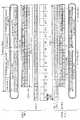
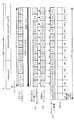
図11はCircular Bufferを用いた場合の送信局と受信局におけるデータの配置構成の一例を示す図である。図11において、送信局NB(Node-B)は送信側の3GPP−LTEにおける無線通信基地局装置を、受信局P−UE(Persistent-User Equipment)は受信側の3GPP−LTEにおける無線通信移動局装置をそれぞれ示している。Persistent-User Equipmentは、Persistent-schedulingが適用されるユーザ端末であり、Persistent-schedulingとは、あらかじめ送受信局間でスケジューリングパターンを決めておくことにより、スケジューリングにかかる制御情報の削減を目的としたスケジューリングのことである。ここでは、受信局P−UEに対する送信局NBにおける送信Circular Bufferの構成、および、受信局P−UEにおける受信Circular Bufferの構成を示す。 FIG. 11 is a diagram illustrating an example of a data arrangement configuration in a transmitting station and a receiving station when a circular buffer is used. In FIG. 11, a transmitting station NB (Node-B) is a wireless communication base station apparatus in 3GPP-LTE on the transmitting side, and a receiving station P-UE (Persistent-User Equipment) is a wireless communication mobile station in 3GPP-LTE on the receiving side. Each device is shown. Persistent-User Equipment is a user terminal to which Persistent-scheduling is applied. Persistent-scheduling is a scheduling aimed at reducing control information related to scheduling by determining a scheduling pattern between transmitting and receiving stations in advance. That is. Here, the configuration of the transmission Circular Buffer in the transmission station NB for the reception station P-UE and the configuration of the reception Circular Buffer in the reception station P-UE are shown.
受信局P−UEは、データ割当があるTTI(Transmission Time Interval)においてCCFI(Control Channel Format Indicator)を参照した後に、データを受信する。ここで、TTIとは、スケジューリングを行う時間単位(例えば1ms)である。CCFIとは、TTI内で制御情報が配置されるOFDMシンボル数を通知する情報である。図11の例では、送信局NBがCCFI=2で送信したデータを、受信局P−UEがCCFI=3と誤って受信した状況を示す。制御情報は、スケジューリングされた受信局P−UEの制御情報であるCCH(Control Channel)で示してある。CCFIは、伝送周波数帯域上のOFDMシンボル#1のいずれかのサブキャリアに割り当てられ、誤り検出符号化がなされていないため、CCFIエラーとなり誤って解釈する可能性が高い。 The receiving station P-UE receives data after referring to a CCFI (Control Channel Format Indicator) in a TTI (Transmission Time Interval) with data allocation. Here, TTI is a time unit (for example, 1 ms) for performing scheduling. CCFI is information for reporting the number of OFDM symbols in which control information is arranged in the TTI. The example of FIG. 11 shows a situation in which the receiving station P-UE erroneously receives CCFI = 3 as data transmitted by the transmitting station NB with CCFI = 2. The control information is indicated by CCH (Control Channel) which is control information of the scheduled receiving station P-UE. CCFI is assigned to any subcarrier of
この場合、受信局P−UEはCCFI=3で受信を行うため、TTI内で3番目のOFDMシンボル#3に配置されたデータD_1を受信欠落してしまう。さらに、受信局P−UEは受信開始地点を4番目のOFDMシンボル#4のデータD_2と判断して受信Circular Bufferへ格納するため、本来はデータD_1から配置されるべき受信Circular BufferにデータD_2から配置されることにより、全体的にずれた状態で受信Circular Bufferへ格納されてしまう。これらの先頭データの欠落とバッファ格納位置のずれにより、初回受信時のパケット誤りが発生する上に、再送時にもずれた状態で合成されるため、パケット誤りを改善できないという課題がある。 In this case, since the receiving station P-UE performs reception with CCFI = 3, data D_1 arranged in the third
本発明は、上記事情に鑑みてなされたもので、その目的は、CCFIエラーが生じた場合であっても、バッファへのデータ格納ミスによる初回受信時のパケット誤りを防ぐことができ、再送時にずれた状態で合成することを回避することが可能な無線通信装置、無線通信システム及び無線通信方法を提供することにある。 The present invention has been made in view of the above circumstances, and an object of the present invention is to prevent a packet error at the time of initial reception due to a data storage error in the buffer even when a CCFI error occurs. An object of the present invention is to provide a wireless communication apparatus, a wireless communication system, and a wireless communication method that can avoid combining in a shifted state.
本発明は、第1に、Persistent-schedulingが適用される受信局に対して、OFDMを用いたデータ伝送を行う送信局となる無線通信装置であって、受信局へ送信するためのデータを格納するCircular Bufferを備え、前記Persistent-schedulingが適用される受信局へ送信するデータに関して、前記Circular Bufferからのデータの読出処理、または、変調後のデータシンボルのOFDMシンボルへの配置処理のいずれかの処理において、逆順にデータ処理を行う送信データ処理部を備える無線通信装置を提供する。
これにより、Persistent-schedulingが適用される受信局がCCFIエラーを引き起こしたとしても、バッファへのデータ格納ミスによる初回受信時のパケット誤りを防ぐことができ、再送時にずれた状態で合成することを回避することが可能となる。A first aspect of the present invention is a wireless communication apparatus serving as a transmitting station that performs data transmission using OFDM to a receiving station to which persistent-scheduling is applied, and stores data to be transmitted to the receiving station With respect to data to be transmitted to a receiving station to which the persistent-scheduling is applied, either data read processing from the circular buffer or modulation data symbol placement processing to an OFDM symbol In processing, a wireless communication apparatus including a transmission data processing unit that performs data processing in reverse order is provided.
As a result, even if a receiving station to which persistent-scheduling is applied causes a CCFI error, it is possible to prevent a packet error at the time of the first reception due to a data storage error in the buffer, and to synthesize in a state shifted at the time of retransmission. It can be avoided.
また、本発明は、第2に、上記第1の無線通信装置であって、前記送信データ処理部は、前記Circular Bufferからのデータの読出処理において、送信するデータの末尾から逆方向にデータを読み出すものを含む。 The second aspect of the present invention is the first wireless communication apparatus according to the first aspect, wherein the transmission data processing unit receives data in the reverse direction from the end of data to be transmitted in the data reading process from the Circular Buffer. Includes what to read.
また、本発明は、第3に、上記第1の無線通信装置であって、前記送信データ処理部は、前記変調後のデータシンボルのOFDMシンボルへの配置処理において、末尾のOFDMシンボルから逆方向にデータを配置するものを含む。 Third, the present invention is the first wireless communication apparatus according to the first aspect, wherein the transmission data processing unit reverses from the last OFDM symbol in the process of arranging the modulated data symbols on the OFDM symbols. Including data to be placed in
また、本発明は、第4に、上記第1の無線通信装置であって、前記送信データ処理部は、前記受信局へ伝送するデータにおいて、1つの送信するための単位(Transport-block)が複数の符号化の単位(Code-block)で構成される場合、すべてのCode-blockデータが各OFDMシンボルに対して均等となるように配置するものを含む。
これにより、Persistent-schedulingが適用される受信局がCCFIエラーを引き起こしたとしても、データ格納ミスによる後続のCode-blockのパケット誤りを防ぐことができ、再送時にずれた状態で合成することを避けることが可能となる。Fourth, the present invention is the first wireless communication apparatus, wherein the transmission data processing unit has one unit (Transport-block) for transmitting data transmitted to the receiving station. In the case of being configured by a plurality of coding units (Code-blocks), it includes a configuration in which all Code-block data are arranged so as to be equal to each OFDM symbol.
As a result, even if a receiving station to which persistent-scheduling is applied causes a CCFI error, it is possible to prevent a subsequent code-block packet error due to a data storage error, and avoid combining in a shifted state at the time of retransmission. It becomes possible.
また、本発明は、第5に、上記第4の無線通信装置であって、前記送信データ処理部は、すべてのCode-blockデータが各OFDMシンボルへ時間方向に均等となるように配置するものを含む。 In addition, according to the present invention, fifthly, in the fourth wireless communication apparatus, the transmission data processing unit is arranged so that all Code-block data is evenly distributed in time direction to each OFDM symbol. including.
また、本発明は、第6に、上記第4の無線通信装置であって、前記送信データ処理部は、すべてのCode-blockデータが各OFDMシンボルへ周波数方向に均等となるように配置するものを含む。 In addition, according to the present invention, sixthly, in the fourth wireless communication apparatus, the transmission data processing unit is arranged so that all the Code-block data is evenly distributed to each OFDM symbol in the frequency direction. including.
また、本発明は、第7に、上記第4の無線通信装置であって、前記送信データ処理部は、すべてのCode-blockデータが、制御チャネルが配置される可能性のあるOFDMシンボルに対してのみ均等となるように配置するものを含む。 In addition, according to the seventh aspect of the present invention, in the fourth wireless communication apparatus, the transmission data processing unit is configured such that all code-block data is transmitted to an OFDM symbol in which a control channel may be arranged. That are arranged so that they are evenly distributed.
また、本発明は、第8に、上記第1の無線通信装置であって、自己の送信局から送信対象とする受信局として、Dynamic-schedulingが適用される第1の受信局とPersistent-schedulingが適用される第2の受信局とを離散的(Distributed)に多重する場合、前記送信データ処理部は、前記Persistent-schedulingが適用される第2の受信局へ送信するデータを伝送区間の末尾のOFDMシンボルから逆方向に配置するものを含む。
これにより、複数の受信局の割り当てを行う際に各受信局のデータ配置が断続的になることを回避できる。この場合、Dynamic-schedulingが適用される第1の受信局の割当領域を時間的に連続させることができ、CCFI値によらず連続受信が可能であるので、受信処理が簡単になる。In addition, according to the present invention, eighthly, in the first wireless communication apparatus, a first receiving station to which dynamic-scheduling is applied and a persistent-scheduling as a receiving station to be transmitted from its own transmitting station. When the transmission data processing unit multiplexes the second reception station to which the Persistent-scheduling is applied, the transmission data processing unit transmits data to be transmitted to the second reception station to which the persistent-scheduling is applied at the end of the transmission section. In the reverse direction from the OFDM symbol.
Thereby, it is possible to avoid intermittent data arrangement of each receiving station when assigning a plurality of receiving stations. In this case, the allocation area of the first receiving station to which dynamic-scheduling is applied can be made continuous in time, and continuous reception is possible regardless of the CCFI value, so that the reception process is simplified.
また、本発明は、第9に、上記第1の無線通信装置であって、前記Persistent-schedulingが適用される受信局への再送時に通知される制御情報に、前回の受信時のCCFI(Control Channel Format Indicator)情報を組み込む制御情報処理部を備えるものを含む。
これにより、Persistent-schedulingが適用される受信局がCCFIエラーを引き起こしたとしても、過剰受信することを防ぐことができ、また、再送時の制御情報より初回受信時にあいまいであったデータ情報を合成して復号できるため、符号化ゲインが得られる。In addition, according to the ninth aspect of the present invention, in the first wireless communication apparatus, the control information notified at the time of retransmission to the receiving station to which the persistent-scheduling is applied is added to the CCFI (Control Including a control information processing unit that incorporates (Channel Format Indicator) information.
As a result, even if a receiving station to which persistent-scheduling is applied causes a CCFI error, it is possible to prevent excessive reception and to synthesize data information that was ambiguous at the time of initial reception from control information at the time of retransmission. Therefore, the coding gain can be obtained.
また、本発明は、第10に、Persistent-schedulingが適用される受信局となり、送信局との間でOFDMを用いたデータ伝送を行う無線通信装置であって、送信局から受信したデータを格納するCircular Bufferを備え、前記送信局よりOFDMシンボルにおいて逆方向に配置されたデータを受信した場合に、前記Circular Bufferへのデータの格納処理において、所定のデータ格納位置に逆方向に並び替えてデータを格納する受信データ処理部を備える無線通信装置を提供する。 The tenth aspect of the present invention is a wireless communication apparatus that performs data transmission using OFDM with a transmitting station, and stores data received from the transmitting station, which is a receiving station to which persistent-scheduling is applied. When receiving data arranged in the reverse direction in the OFDM symbol from the transmitting station, in the data storing process in the Circular Buffer, the data is rearranged in the reverse direction to a predetermined data storage position. A wireless communication apparatus provided with a received data processing unit for storing data.
また、本発明は、第11に、上記第10の無線通信装置であって、前記受信データ処理部は、前記送信局から伝送されるデータにおいて、1つの送信するための単位(Transport-block)が複数の符号化の単位(Code-block)で構成される場合、すべてのCode-blockデータが各OFDMシンボルに対して均等となるように逆方向に配置されたデータを、それぞれのCode-blockごとに逆方向に並び替えて格納するものを含む。 In addition, according to the present invention, in the eleventh aspect, in the tenth wireless communication apparatus, the reception data processing unit transmits one unit (Transport-block) in data transmitted from the transmission station. Is composed of multiple coding units (Code-block), the data arranged in the reverse direction so that all Code-block data is equal to each OFDM symbol, This includes items that are sorted and stored in the reverse direction.
また、本発明は、第12に、上記第10の無線通信装置であって、送信局が送信対象とする受信局として、Dynamic-schedulingが適用される他の受信局とPersistent-schedulingが適用される自己の受信局とが離散的(Distributed)に多重された場合、前記受信データ処理部は、自己の受信局用の末尾のOFDMシンボルから逆方向に配置されたデータを、逆順に元に並び替えて格納するものを含む。 The twelfth aspect of the present invention is the tenth wireless communication apparatus according to the tenth aspect, in which Persistent-scheduling is applied as a receiving station to which the transmitting station is to transmit with other receiving stations to which Dynamic-scheduling is applied. The received data processing unit arranges the data arranged in the reverse direction from the last OFDM symbol for the own receiving station in the reverse order. Includes items that are stored instead.
また、本発明は、第13に、送信局と、Persistent-schedulingが適用される受信局との間でOFDMを用いたデータ伝送を行う無線通信システムであって、
受信局へ送信するためのデータを格納するCircular Bufferを備え、前記Persistent-schedulingが適用される受信局へ送信するデータに関して、前記Circular Bufferからのデータの読出処理、または、変調後のデータシンボルのOFDMシンボルへの配置処理のいずれかの処理において、逆順にデータ処理を行う送信データ処理部を備える送信局である第1の無線通信装置と、
送信局から受信したデータを格納するCircular Bufferを備え、前記Persistent-schedulingが適用される受信局となり、前記送信局から逆方向に配置されたデータを受信した場合に、前記Circular Bufferへのデータの格納処理において、所定のデータ格納位置に逆方向にデータを格納する受信データ処理部を備える受信局である第2の無線通信装置と、を有する無線通信システムを提供する。Moreover, the present invention, in a thirteenth aspect, is a wireless communication system that performs data transmission using OFDM between a transmitting station and a receiving station to which persistent-scheduling is applied,
A Circular Buffer for storing data to be transmitted to the receiving station is provided, and with respect to data to be transmitted to the receiving station to which the persistent-scheduling is applied, a process of reading data from the Circular Buffer or a data symbol after modulation A first wireless communication apparatus that is a transmission station including a transmission data processing unit that performs data processing in reverse order in any of the arrangement processes to OFDM symbols;
A circular buffer for storing data received from the transmitting station is provided, and becomes a receiving station to which the persistent-scheduling is applied.When data arranged in the reverse direction is received from the transmitting station, the data of the data to the circular buffer is received. In a storage process, a wireless communication system is provided that includes a second wireless communication apparatus that is a receiving station including a reception data processing unit that stores data in a reverse direction at a predetermined data storage position.
また、本発明は、第14に、Persistent-schedulingが適用される受信局に対して、OFDMを用いたデータ伝送を行う送信局となる無線通信装置における無線通信方法であって、前記Persistent-schedulingが適用される受信局へ送信するデータに関して、前記受信局へ送信するためのデータを格納するCircular Bufferからのデータの読出処理、または、変調後のデータシンボルのOFDMシンボルへの配置処理のいずれかの処理において、逆順にデータ処理を行う送信データ処理ステップを有する無線通信方法を提供する。 Furthermore, the present invention provides, in a fourteenth aspect, a wireless communication method in a wireless communication apparatus that is a transmitting station that performs data transmission using OFDM to a receiving station to which Persistent-scheduling is applied, the Persistent-scheduling For data to be transmitted to a receiving station to which is applied, either a process of reading data from a circular buffer that stores data to be transmitted to the receiving station, or a process of arranging modulated data symbols in OFDM symbols In this process, a wireless communication method having a transmission data processing step for performing data processing in reverse order is provided.
また、本発明は、第15に、Persistent-schedulingが適用される受信局となり、送信局との間でOFDMを用いたデータ伝送を行う無線通信装置における無線通信方法であって、前記送信局から逆方向に配置されたデータを受信した場合に、前記送信局から受信したデータを格納するCircular Bufferへのデータの格納処理において、所定のデータ格納位置に逆方向にデータを格納する受信データ処理ステップを有する無線通信方法を提供する。 According to a fifteenth aspect of the present invention, there is provided a wireless communication method in a wireless communication apparatus that is a receiving station to which Persistent-scheduling is applied and performs data transmission using OFDM with the transmitting station. A reception data processing step of storing data in the reverse direction at a predetermined data storage position in the data storage process in the circular buffer for storing the data received from the transmitting station when data arranged in the reverse direction is received A wireless communication method is provided.
本発明によれば、CCFIエラーが生じた場合であっても、バッファへのデータ格納ミスによる初回受信時のパケット誤りを防ぐことができ、再送時にずれた状態で合成することを回避することが可能な無線通信装置、無線通信システム及び無線通信方法を提供できる。 According to the present invention, even when a CCFI error occurs, a packet error at the time of initial reception due to a data storage error in the buffer can be prevented, and it is possible to avoid combining in a shifted state at the time of retransmission. A possible wireless communication apparatus, wireless communication system, and wireless communication method can be provided.
100 送信局
101 CRC部
102 符号化部
103 送信Circular Buffer
104 変調部
105 多重部
106 IFFT部
107 送信RF部
108 アンテナ
109 受信RF部
110 復調部
111 復号部
112 制御部
300 受信局
301 アンテナ
302 受信RF部
303 FFT部
304 分離部
305 復調部
306 受信Circular Buffer
307 復号部
308 誤り検出部
309 回線品質推定部
310 制御信号生成部
311 符号化部
312 変調部
313 送信RF部100
104
307
本実施形態では、本発明に係る無線通信システム、無線通信装置及び再送制御方法の一例として、OFDMを用いた無線伝送方式で通信を行う場合の構成例を示す。以下の実施形態の説明では、FDD(Frequency Division Duplex)システムを仮定する。なお、TDD(Time Division Duplex)システムでも実施可能である。また、データを送信する側を送信局、データを受信する側を受信局とする。なお、下記の実施形態は説明のための一例であり、本発明はこれに限定されるものではない。 In the present embodiment, as an example of a wireless communication system, a wireless communication apparatus, and a retransmission control method according to the present invention, a configuration example in the case of performing communication by a wireless transmission scheme using OFDM is shown. In the following description of the embodiment, an FDD (Frequency Division Duplex) system is assumed. Note that the present invention can also be implemented in a TDD (Time Division Duplex) system. In addition, a side that transmits data is a transmitting station, and a side that receives data is a receiving station. The following embodiment is an example for description, and the present invention is not limited to this.
(第1の実施形態)
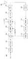
図1は本発明の実施形態における送信局のブロック構成を示す図である。送信局100となる無線通信装置は、CRC部101、符号化部102、送信Circular Buffer103、変調部104、多重部105、IFFT部106、送信RF部107、アンテナ108、受信RF部109、復調部110、復号部111、制御部112を備えて構成される。本実施形態では、例えば、セルラーシステムにおいて無線通信基地局装置と無線通信移動局装置との間で通信を行う場合に、無線通信基地局装置NB(Node-B)が送信側の送信局、無線通信移動局装置UE(User Equipment)が受信側の受信局となる場合を例示する。また、受信局は、Persistent-schedulingが適用されるPersistent-User Equipment(以下、Persistent-UEと記載)である場合を想定し、CCFIを参照して伝送区間としてのTTI内における制御情報(制御チャネル)が配置されるOFDMシンボル数を認識し、データシンボルを特定する動作を行うものとする。(First embodiment)
FIG. 1 is a diagram showing a block configuration of a transmitting station in the embodiment of the present invention. The radio communication apparatus serving as the
CRC部101は、入力される送信データを誤り検出符号化(Cyclic Redundancy Check)し、CRCがかけられたデータを符号化部102へ出力する。符号化部102は、CRCがかけられたデータをマザー符号化率(例えば、符号化率R=1/3)でターボ符号化し、導出された符号語(符号化されたデータ)を送信Circular Buffer103へ出力する。 The
送信Circular Buffer103は、送信データを格納して保持する巡回読出型バッファを構成するメモリを有しており、制御部112から入力される送信データサイズ、符号化率、RVパラメータ、UE属性(受信側のユーザ端末属性)に従って、格納されたデータの中から送信する符号語データを読み出して変調部104へ出力する。ここで、UE属性として、割当UEである受信局のUE属性がDynamic-schedulingが適用されるDynamic-User Equipment(以下、Dynamic-UEと記載)であった場合、所定のデータ開始地点から順方向に読み出した符号語データを変調部104へ出力する。本実施形態では、送信データのデータ格納位置を示すデータ開始地点として、例えば事前に通知されるRVパラメータで指示された開始地点を用いるが、これに限るものではない。 The transmission
一方、割当UEである受信局のUE属性がPersistent-schedulingが適用されるPersistent-UEであった場合、RVパラメータで指示された開始地点から送信データサイズに相当する領域において、すなわち開始地点から送信データサイズ分先のアドレス位置までについて、末尾から逆方向に読み出した符号語データを変調部104へ出力する。本実施形態では、受信局がPersistent-UEである場合を主に説明するが、この場合の送信Circular Buffer103の読出処理の詳細については、後述する。 On the other hand, when the UE attribute of the receiving station that is the assigned UE is Persistent-UE to which Persistent-scheduling is applied, transmission is performed from the start point indicated by the RV parameter in the area corresponding to the transmission data size, that is, from the start point. The code word data read in the reverse direction from the end up to the address position ahead of the data size is output to the
変調部104は、送信Circular Buffer103から入力された順に符号語データを、制御部112から入力される変調多値数で変調してデータシンボルを生成し、多重部105へ出力する。
多重部105は、変調部104から入力されるデータシンボルを、制御部112から入力される割当RB(Resource Block)番号に対応する周波数サブキャリアへ配置する。また、多重部105では、制御部112から入力されるCCFI値に従って、何番目のOFDMシンボルからデータシンボルを配置するのかを決定する。さらに、多重部105は、データシンボル、制御部112から入力される制御情報、パイロット信号(参照信号)を多重する。上記データシンボルをOFDMシンボルへ配置する処理の詳細については、送信Circular Bufferの読出処理とともに後述する。 Multiplexing
IFFT部106は、多重部105より入力される情報に対してIFFTを行って、マルチキャリア信号であるOFDMシンボルを生成する。送信RF部107は、ベースバンド信号をRF信号に周波数変換し、このRF信号の送信信号をアンテナ108より受信局へ送信する。
受信RF部109は、受信局から送信された制御信号をアンテナ108より受信し、RF信号の受信信号をベースバンド信号に周波数変換する。受信局から制御信号としては、受信品質を示すCQI(Channel Quality Indicator)、および受信の可否を示すACK(Acknowledgement)/NACK(Negative Acknowledgement)信号などが含まれる。 The
復調部110は、制御信号(CQI、ACK/NACK信号)を復調して復号部111へ出力する。復号部111は、復調された制御信号(CQI、ACK/NACK信号)を復号して制御部112)へ出力する。
制御部112は、復号部111から入力された各受信局からの制御信号(CQI、ACK/NACK信号)に基づいて、符号化率、変調多値数、割当RB番号、CCFI値、および再送を制御する。制御部112は、生成した符号化率の情報を送信Circular Buffer103へ出力し、変調多値数を変調部104へ出力し、割当RB番号、CCFI値および制御情報を多重部105へ出力する。なお、受信局が報告するCQIは、平均SINR(Signal-to-Interference plus Noise power Ratio)でも、平均SIR(Signal-to-Interference Ratio)でも、MCS(Modulation and Coding Scheme)パラメータでも構わない。上記送信局の構成において、送信Circular Buffer103、多重部105、および制御部112が送信データ処理部の機能を実現し、制御部112が制御情報処理部の機能を実現する。 Based on the control signal (CQI, ACK / NACK signal) from each receiving station input from decoding
次に、第1の実施形態の送信局における主要な処理動作の詳細を説明する。ここでは、送信Circular Buffer103の読出処理と、多重部105におけるデータシンボルをOFDMシンボルへ配置する処理との2点について詳述する。 Next, details of main processing operations in the transmitting station of the first embodiment will be described. Here, two points of reading processing of
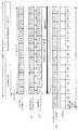
図2は第1の実施形態の送信局におけるデータ処理およびデータの配置構成の一例を示す図である。図2では、Persistent-UEのデータチャネルの配置例として、Persistent-UEのデータチャネルを送信Circular Bufferから読み出し、変調を介し、対応するOFDMシンボルへ配置するまでの処理状況を示している。なお、ここではCCFI=2の場合を説明する。処理手順は以下の(A1)〜(A3)の3段階であり、図2中の(A1)〜(A3)と対応する。 FIG. 2 is a diagram illustrating an example of data processing and data arrangement in the transmitting station according to the first embodiment. In FIG. 2, as an example of the arrangement of the persistent-UE data channel, a processing situation is shown from when the persistent-UE data channel is read from the transmission circular buffer and arranged to the corresponding OFDM symbol via modulation. Here, the case of CCFI = 2 will be described. The processing procedure is the following three stages (A1) to (A3), and corresponds to (A1) to (A3) in FIG.
(A1)送信Circular Bufferの読出処理
送信Circular Buffer103は、制御部112から指示されたRVパラメータと送信データサイズに基づいて、送信する符号語データを特定する。ここでは、送信する符号語データがD_1〜D_12であるとする。なお、符号語データD_1〜D_12のうち、D_1〜D_4は符号語のシステマティックビット(図2上段のInterleaved S)に対応し、D_5〜D_12は符号語のパリティビット(図2上段のInterleaved and interlaced P1 and P2)に対応する。
次に、特定した符号語データを末尾から先頭まで逆方向に順にD_12、D_11、…、D_1と読み出し、変調部104へ出力する。(A1) Transmission Circular Buffer Reading Process The
Next, the identified codeword data is read in the reverse direction from the end to the beginning as D_12, D_11,..., D_1, and output to the
(A2)変調処理
変調部104は、送信Circular Buffer103から入力された順に符号語データD_12〜D_1を、制御部112から入力される変調多値数で変調してデータシンボルを生成し、多重部105へ出力する。(A2) Modulation processing The
(A3)データシンボルをOFDMシンボルへ配置する処理
多重部105は、制御部112から入力されるCCFI値(=2)に基づき、割当RB番号のサブキャリアに対して、3番目のOFDMシンボル#3から順に、変調部104から入力されるデータシンボルD_12〜D_1を配置する。図2の例では、3番目のOFDMシンボル#3にD_12、4番目のOFDMシンボル#4にD_11を配置し、5番目から末尾の14番目のOFDMシンボル#5〜#14についても同様にして、順にデータシンボルD_10〜D_1を配置する。なお、本例では、OFDMシンボルは、1TTI(1つの伝送区間)において#1〜#14の14のシンボルを持つものとする。(A3) Processing for Arranging Data Symbol to OFDM
以上の処理により、OFDMシンボルには、1番目及び2番目のOFDMシンボル#1、#2に制御チャネルCCHが配置され、3番目から14番目までのOFDMシンボル#3〜#14にデータシンボルD_12〜D_1が順に配置される。すなわち、送信Circular Bufferから読み出され、変調されたデータシンボルは、OFDMシンボルにおいて、元の送信Circular Buffer上の符号語データとは逆方向の状態で、制御チャネルCCHの後に順番に配置される。 As a result of the above processing, the control channel CCH is arranged in the first and second
図3は本発明の実施形態における受信局のブロック構成を示す図である。受信局300となる無線通信装置は、アンテナ301、受信RF部302、FFT部303、分離部304、復調部305、受信Circular Buffer306、復号部307、誤り検出部308、回線品質推定部309、制御信号生成部310、符号化部311、変調部312、送信RF部313を備えて構成される。 FIG. 3 is a diagram showing a block configuration of a receiving station in the embodiment of the present invention. The wireless communication apparatus serving as the
受信RF部302は、送信局から送信された信号をアンテナ301より受信し、RF信号の受信信号をベースバンド信号に周波数変換する。FFT部303は、受信OFDMシンボルに対してFFTを行って周波数領域の信号に変換し、受信データ信号を分離部304へ出力する。 The
分離部304は、受信データ信号をデータシンボルと制御情報(割当RB番号、符号化率、変調多値数、RVパラメータ、CCFI値、UE属性)とに分離し、割当RB番号に対応する周波数サブキャリアのデータシンボルを復調部305へ出力するとともに、制御情報(変調多値数)を復調部305へ出力し、制御情報(符号化率、RVパラメータ、UE属性)を受信Circular Buffer306へ出力する。また、分離部304は、受信パイロット信号を回線品質推定部309へ出力する。このとき、分離部304は、CCFI値に従って、何番目のOFDMシンボルからデータシンボルが配置されているのかを特定し、データに対応するOFDMシンボルに配置されているデータシンボルのみ、復調部305へ出力する。 Separating
復調部305は、分離部304から入力されるデータシンボルを、制御情報で通知された変調多値数に従って復調する。復調された情報(復調後のデータシンボルから得られる尤度情報)は、受信Circular Buffer306へ出力される。
受信Circular Buffer306は、受信データを格納して保持する巡回読出型バッファを構成するメモリを有しており、分離部304から入力される制御情報(符号化率、RVパラメータ、UE属性)に基づいて、復調部305で復調された情報を順に格納する。さらに、受信Circular Buffer306は、格納された復調情報を読み出して復号部307へ出力する。ここで、UE属性として、割当UEである受信局のUE属性がDynamic-schedulingが適用されるDynamic-UEであった場合、所定のデータ開始地点から受信したOFDMシンボルと同じ順方向に復調された情報を受信Circular Buffer306へ格納する。本実施形態では、受信データのデータ格納位置を示すデータ開始地点として、例えば事前に通知されるRVパラメータで指示された開始地点を用いるが、これに限るものではない。 The reception
一方、割当UEである受信局のUE属性がPersistent-schedulingが適用されるPersistent-UEであった場合、RVパラメータで指示された開始地点から受信データサイズに相当する領域において、すなわち開始地点から受信データサイズ分先のアドレス位置までについて、受信したOFDMシンボルと逆方向に復調された情報を受信Circular Buffer306へ格納する。 On the other hand, when the UE attribute of the receiving station that is the assigned UE is Persistent-UE to which Persistent-scheduling is applied, reception is performed in an area corresponding to the received data size from the start point indicated by the RV parameter, that is, from the start point. The information demodulated in the direction opposite to the received OFDM symbol is stored in the receiving
また、受信Circular Buffer306は、誤り検出部308からACK信号が入力された場合にのみ、すでに格納している受信データを廃棄する。本実施形態では、受信局がPersistent-UEである場合を主に説明するが、この場合の受信Circular Buffer306の格納処理の詳細については、後述する。 In addition, the reception
復号部307は、受信Circular Buffer306から入力されるデータシンボルを誤り訂正復号し、復号ビット列を得る。復号ビット列は、誤り検出部308へ出力される。誤り検出部308は、復号部307から入力される復号ビット列に対して誤り検出復号化(CRC)を行う。誤り検出の結果、復号ビットに誤りがある場合には応答信号としてNACK信号を生成し、復号ビットに誤りがない場合には応答信号としてACK信号を生成し、制御信号生成部310へ出力する。また、誤り検出部308は、復号ビット列に誤りが無い場合にはその復号ビット列を受信ビット列として出力する。 The
回線品質推定部309は、受信パイロット信号から回線品質(例えばSINR)を推定する。SINR推定値は、制御信号生成部310へ出力される。制御信号生成部310は、回線品質推定部309から入力されるSINR推定値等によるCQIと、誤り検出部308から入力されるACK/NACK信号とからフィードバック情報用のフレームを生成し、符号化部311へ出力する。 Channel
符号化部311は、制御信号生成部310から入力されるフィードバック情報の符号化を行う。変調部312は、符号化されたフィードバック情報の変調を行い、送信RF部313へ出力する。送信RF部313は、符号化および変調されたベースバンド信号をRF信号に周波数変換し、このRF信号の送信信号をアンテナ301より送信局へ送信する。上記受信局の構成において、受信Circular Buffer306が受信データ処理部の機能を実現する。 The
次に、第1の実施形態の受信局における主要な処理動作の詳細を説明する。ここでは、受信Circular Buffer306への格納処理について詳述する。 Next, details of main processing operations in the receiving station of the first embodiment will be described. Here, the storing process in the receiving
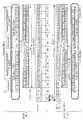
図4は第1の実施形態の受信局におけるデータ処理およびデータの配置構成の一例を示す図である。図4では、Persistent-UEのデータチャネルの配置例として、Persistent-UEのデータチャネルに含まれる受信データシンボルを特定し、復調を介し、受信Circular Bufferへ格納するまでの処理状況を示している。なお、ここでは送信局がCCFI=2で送信した情報を、受信局がCCFI=3と誤って受信した場合について説明する。CCFIは誤り検出符号化がなされていないため、CCFIエラーとなり誤認識する可能性が高い。処理手順は以下の(B1)〜(B3)の3段階であり、図4中の(B1)〜(B3)と対応する。 FIG. 4 is a diagram illustrating an example of data processing and data arrangement in the receiving station according to the first embodiment. In FIG. 4, as an example of the arrangement of the persistent-UE data channel, a processing state from the reception data symbol included in the persistent-UE data channel being specified to being stored in the reception circular buffer via demodulation is shown. Here, a case will be described in which information transmitted by the transmitting station with CCFI = 2 is erroneously received by the receiving station as CCFI = 3. Since CCFI has not been subjected to error detection coding, there is a high possibility of being erroneously recognized as a CCFI error. The processing procedure is the following three stages (B1) to (B3), and corresponds to (B1) to (B3) in FIG.
(B1)OFDMシンボルから受信データシンボルを特定する処理
分離部304は、CCFI値(=3)に従って、4番目のOFDMシンボル#4からデータシンボルが配置されていることを特定する。そして、特定したデータシンボルを復調部305へ出力する。図4の例では、4番目のOFDMシンボル#4がデータシンボルD_11に、5番目のOFDMシンボル#5がデータシンボルD_10にそれぞれ対応する。6番目から末尾の14番目のOFDMシンボル#6〜#14についても同様にして、順にデータシンボルD_9〜D_1が対応する。(B1) Processing for specifying received data symbols from OFDM
(B2)復調処理
復調部305は、分離部304から入力された順にデータシンボルD_11〜D_1を、事前に通知された変調多値数で復調して復調情報を生成し、受信Circular Buffer306へ出力する。(B2) Demodulation
(B3)受信Circular Bufferへの格納処理
受信Circular Buffer306は、所定のデータ格納位置として、事前に通知されたRVパラメータで指示された開始地点から受信データサイズに相当する領域において、復調情報(復調後のデータシンボル)の末尾から先頭までを逆方向に並び替えてD_1〜D_11として格納する。(B3) Storage processing in the reception circular buffer The reception
以上の処理により、受信Circular Buffer306には、復調情報D_1〜D_11のうち、D_1〜D_4が符号語のシステマティックビット(図4下段のInterleaved S)に対応する位置に配置され、D_5〜D_11が符号語のパリティビット(図4下段のInterleaved and interlaced P1 and P2)に対応する位置に配置されて格納される。よって、受信Circular Bufferにおける格納ずれが発生しない。この場合、OFDMシンボルから制御情報と分離され、復調されたデータシンボルは、受信Circular Bufferにおいて、受信したOFDMシンボルとは逆方向の状態で、つまり送信側での元の送信Circular Buffer上の符号語データと同じ方向に並んだ状態に復元されて配置されることになる。上記例では、受信局におけるCCFI値の誤認識により受信データシンボルD_12の抜け落ちが生じ、この末端側のデータ欠落によって符号化ゲインが若干小さくなるものの、受信Circular Bufferでのデータ格納ずれや先頭のデータ欠落による受信誤りは発生しない。 As a result of the above processing, D_1 to D_4 of demodulation information D_1 to D_11 are arranged at positions corresponding to the systematic bits of the codeword (Interleaved S in the lower part of FIG. 4), and D_5 to D_11 are codewords. Are stored in positions corresponding to the parity bits (Interleaved and interlaced P1 and P2 in the lower part of FIG. 4). Therefore, a storage shift does not occur in the receiving Circular Buffer. In this case, the demodulated data symbol separated from the control information from the OFDM symbol is a codeword in the receiving Circular Buffer in the opposite direction to the received OFDM symbol, that is, on the transmitting side on the original transmitting Circular Buffer. The data is restored and arranged in the same direction as the data. In the above example, the received data symbol D_12 is dropped due to erroneous recognition of the CCFI value at the receiving station, and the coding gain is slightly reduced due to the loss of data on the end side. No reception error due to omission occurs.
上記のように、本実施形態によれば、受信局がPersistent-schedulingが適用されるPersistent-UEであり、CCFIを参照して制御チャネルCCHが配置されるOFDMシンボル数を認識し、データシンボルを特定してCircular Bufferに格納する動作を行う際に、受信局でCCFIエラーが発生した場合であっても、データ格納ミスによる初回受信時のパケット誤りを防ぐことができ、再送時にずれた状態で合成することを避けることができる。 As described above, according to the present embodiment, the receiving station is a Persistent-UE to which Persistent-scheduling is applied, recognizes the number of OFDM symbols in which the control channel CCH is arranged with reference to the CCFI, and converts the data symbols. Even when a CCFI error occurs at the receiving station when performing the operation to specify and store in the circular buffer, it is possible to prevent packet error at the first reception due to data storage error, You can avoid synthesizing.
また、本実施形態は、元のデータ配置とは逆方向に送信Circular Bufferから読み出したり受信Circular Bufferへ格納するという単純な処理であるため、処理にかかるステップや構成を簡易なものとすることができる。また、送信Circular Bufferや受信Circular Bufferにおいて、データの連続性を保持でき、送信処理や受信処理において連続的な処理が可能となる。したがって、CCFI値によって送信Circular Bufferの読出方向や受信Circular Bufferへの格納方向が変化することや、複数の受信局の割り当てによってデータ配置が断続的になることなどを回避でき、各種条件に対応した処理の複雑化を抑止できる。 In addition, since this embodiment is a simple process of reading from the transmission circular buffer and storing it in the reception circular buffer in the opposite direction to the original data arrangement, the steps and configuration related to the process may be simplified. it can. Further, data continuity can be maintained in the transmission circular buffer and the reception circular buffer, and continuous processing can be performed in transmission processing and reception processing. Therefore, it is possible to avoid changes in the reading direction of the transmitting circular buffer and the storing direction in the receiving circular buffer depending on the CCFI value, and intermittent arrangement of data due to the allocation of multiple receiving stations. Processing complexity can be suppressed.
(第2の実施形態)
第2の実施形態は、1つの送信するための単位(Transport-block)が複数の符号化の単位(Code-block)で構成される場合の例を示す。本実施形態では、1Transport-blockが複数のCode-blockで構成される場合、すべてのCode-blockデータが各OFDMシンボルへ均等となるように配置する。(Second Embodiment)
The second embodiment shows an example in which one transmission unit (Transport-block) is composed of a plurality of encoding units (Code-block). In this embodiment, when one Transport-block is composed of a plurality of Code-blocks, all the Code-block data are arranged so as to be equal to each OFDM symbol.
第2の実施形態の送信局、受信局のブロック構成は、図1、図3に示した第1の実施形態と同様である。第2の実施形態では、図1に示した送信Circular Buffer103の読出処理と、図3に示した受信Circular Buffer306への格納処理とが上述した第1の実施形態と異なる。以下、具体例を示して説明する。 The block configurations of the transmitting station and the receiving station of the second embodiment are the same as those of the first embodiment shown in FIGS. In the second embodiment, the process of reading the
図5は第2の実施形態におけるデータ処理およびデータの配置構成の一例を示す図である。図5においては、第1の実施形態と同様、送信局が無線通信基地局装置NB、受信局がPersistent-UEである無線通信移動局装置P−UEの場合を示している。この例では、1Transport-blockが2つのCode-blockで構成され、それぞれのCode-block_1(CB1),Code-block_2(CB2)は、1〜12の変調されたデータシンボルで構成されているものとする。すなわち、Code-block_1(CB1)はCB1_1〜CB1_6において1〜12のデータシンボルを有し、Code-block_2(CB2)はCB2_1〜CB2_6において1〜12のデータシンボルを有している。1Transport-blockのデータサイズがCode-blockの上限を超える場合は、複数のCode-blockに分割して処理が行われる。 FIG. 5 is a diagram showing an example of data processing and data arrangement configuration in the second embodiment. FIG. 5 shows the case of the radio communication mobile station apparatus P-UE in which the transmission station is the radio communication base station apparatus NB and the reception station is the persistent-UE, as in the first embodiment. In this example, one Transport-block is composed of two Code-blocks, and each Code-block_1 (CB1) and Code-block_2 (CB2) is composed of 1 to 12 modulated data symbols. To do. That is, Code-block_1 (CB1) has 1 to 12 data symbols in CB1_1 to CB1_6, and Code-block_2 (CB2) has 1 to 12 data symbols in CB2_1 to CB2_6. When the data size of one Transport-block exceeds the upper limit of Code-block, the process is performed by dividing into a plurality of Code-blocks.
まず、第2の実施形態における送信Circular Buffer103の読出処理を説明する。なお、ここでは送信局がCCFI=2で送信した情報を、受信局がCCFI=3と誤って受信した場合について説明する。 First, the reading process of the
送信Circular Buffer103は、制御部112から指示されたRVパラメータと送信データサイズに基づいて、送信する符号語データを特定する。次に、特定したそれぞれのCode-blockの符号語データを末尾から先頭まで逆方向に順に読み出し、変調部104へ出力する。その際、Code-block_1およびCode-block_2の符号語データが各OFDMシンボルへ均等となるように、時間方向に対して均等に読み出す。そして、変調部104で読み出した符号語データを変調した後、多重部105で各OFDMシンボルへ2つのCode-blockが均等となるようにデータシンボルを配置する。これにより、元の送信Circular Buffer上の符号語データとは逆方向の状態で、各OFDMシンボルに対して、2つのCode-blockのデータシンボルが時間方向に均等な状態となって配置される。
次に、第2の実施形態における受信Circular Buffer306への格納処理を説明する。分離部304でCCFI値に従ってデータシンボルが特定されて分離され、復調部305でデータシンボルが復調されて復調情報が生成される。 Next, the storing process to the
受信Circular Buffer306は、事前に通知されたRVパラメータで指示された開始地点から、復調情報の末尾から先頭までをそれぞれのCode-blockごとに逆方向に並び替えて格納する。その際、時間方向に対して均等に配置されたCode-block_1およびCode-block_2の復調情報を、それぞれのCode-block_1,Code-block_2の情報としてほぼ等しいサイズに2分割して格納する。これにより、受信Circular Buffer306において、受信したOFDMシンボルとは逆方向の状態で、つまり送信側での元の送信Circular Buffer上の符号語データと同じ方向の状態に各Code-blockが復元されて配置される。
図5の例では、受信局におけるCCFI値の誤認識により各Code-blockの受信データシンボル12の抜け落ちが生じ、この末端側のデータ欠落によって符号化ゲインが若干小さくなるものの、すべてのCode-blockにおいて受信Circular Bufferでのデータ格納ずれや先頭のデータ欠落による受信誤りは発生しない。 In the example of FIG. 5, the
このように、本実施形態によれば、1Transport-blockが複数のCode-blockで構成される場合において、受信局のPersistent-UEがCCFIエラーを引き起こしたとしても、データ格納ミスによる後続のCode-blockのパケット誤りを防ぐことができ、再送時にずれた状態で合成することを避けることができる。 Thus, according to the present embodiment, when one Transport-block is composed of a plurality of Code-blocks, even if the Persistent-UE of the receiving station causes a CCFI error, the subsequent Code- It is possible to prevent block packet errors, and to avoid combining in a shifted state during retransmission.
(第3の実施形態)
第3の実施形態は、Persistent-UEに対して再送時に通知される制御情報に、前回の受信TTIのCCFI情報を組込んだ例を示す。(Third embodiment)
The third embodiment shows an example in which CCFI information of the previous reception TTI is incorporated in the control information notified to the Persistent-UE at the time of retransmission.
第3の実施形態の送信局、受信局のブロック構成は、図1、図3に示した第1の実施形態と同様である。第3の実施形態では、図1に示した制御部112における制御情報が上述した第1の実施形態と異なる。以下、具体例を示して説明する。 The block configurations of the transmitting station and the receiving station of the third embodiment are the same as those of the first embodiment shown in FIGS. In the third embodiment, the control information in the
図6は第3の実施形態におけるデータ処理およびデータの配置構成の一例を示す図である。図6においては、第1の実施形態と同様、送信局が無線通信基地局装置NB、受信局がPersistent-UEである無線通信移動局装置P−UEの場合を示している。 FIG. 6 is a diagram illustrating an example of data processing and data arrangement in the third embodiment. FIG. 6 shows the case of the radio communication mobile station apparatus P-UE in which the transmission station is the radio communication base station apparatus NB and the reception station is the persistent-UE, as in the first embodiment.
この例では、1フレーム(例えば10ms)が#1〜#10のTTI(例えば1TTI=1ms)で構成される場合に、Persistent-UEの受信局が1番目のTTI#1で制御情報(DL-grant)を受信し、5番目のTTI#5でデータ受信を行い、再送となった場合に9番目のTTI#9で再送時の制御情報(DL-grant)を受信するものとする。ここでは初回受信および再送1回までを想定する。また、受信局は、CCFIがいずれの値であっても、初回受信時に4〜14番目のOFDMシンボル#4〜#14のみを使用して復号処理を行う。すなわち、CCFI値によらず制御チャネルCCHが配置される可能性の無いOFDMシンボルのみを復号に用いる。 In this example, when one frame (for example, 10 ms) is composed of TTIs of # 1 to # 10 (for example, 1 TTI = 1 ms), the receiving station of the Persistent-UE receives control information (DL- grant) is received, data is received at the
この場合、CCFI=2であるとすると、受信データとしては3番目のOFDMシンボル#3にデータD_12が配置されるが、2〜3番目のOFDMシンボル#2〜#3のデータは初回受信時には復号に使用せずに一旦格納だけしておく。これによって、例えばCCFI=2をCCFI=1と誤るなど、値が小さい方向にCCFIエラーが生じた場合の過剰受信を回避できる。 In this case, if CCFI = 2, the data D_12 is arranged in the third
第3の実施形態では、送信局の制御部112は、Persistent-UEの受信局に対して再送時の制御情報(DL-grant)に初回送信時のCCFI情報を含めるようにする。そして、受信局では、再送時の制御情報内に含まれるCCFI情報を参照し、信頼度の高いCCFI値を得る。これにより、受信局は、再送時の制御情報内に含まれるCCFI情報を用いて再送の場合の受信処理を行い、初回受信時にあいまいであった情報(図6の例ではD_12)を合成して復号できるため、符号化ゲインを得ることができる。 In the third embodiment, the
このように、本実施形態によれば、受信局のPersistent-UEがCCFIエラーを引き起こしたとしても、過剰受信することを防ぐことができ、また、再送時の制御情報より初回受信時にあいまいであったデータ情報を合成して復号できるため、符号化ゲインが得られる。 As described above, according to this embodiment, even if the Persistent-UE of the receiving station causes a CCFI error, it is possible to prevent excessive reception, and it is ambiguous at the time of initial reception from the control information at the time of retransmission. Since the data information can be synthesized and decoded, a coding gain can be obtained.
(変形例)
図7は本実施形態の第1変形例におけるデータ処理およびデータの配置構成の一例を示す図である。第1変形例として、送信Circular Buffer103の読出処理と、多重部105におけるデータシンボルのOFDMシンボルへの配置処理を変更した例を示す。(Modification)
FIG. 7 is a diagram showing an example of data processing and data arrangement configuration in the first modification of the present embodiment. As a first modification, an example in which the reading process of the transmission
上記の実施形態では、送信Circular Buffer103の読出処理を逆方向に行う例について記載したが、第1変形例ではこの代わりに、送信Circular Buffer103の読出処理を順方向に行い、かつ、多重部105において、変調したデータシンボルをTTI末尾のOFDMシンボル#14から逆方向に配置していく処理を行うようにする。なお、受信側での受信Circular Buffer306への格納処理は、第1〜第3の実施形態と同様である。 In the above embodiment, the example in which the reading process of the
この第1変形例では、例えば図2の処理(A1)〜(A3)の代わりに、図7の処理(A1)′〜(A3)′を実行する。この場合、送信Circular Buffer103から符号語データD_1〜D_12をそのまま順方向に読み出し、変調部104で変調した後、多重部105において、14番目のOFDMシンボル#14から3番目のOFDMシンボル#3まで逆方向にデータシンボルを配置する。これにより、OFDMシンボルには、データシンボルがD_12、D_11、…、D_1のように逆方向の状態で順に配置される。 In the first modification, for example, the processes (A1) ′ to (A3) ′ of FIG. 7 are executed instead of the processes (A1) to (A3) of FIG. In this case, codeword data D_1 to D_12 are read from the transmission
このような第1変形例の処理によっても、上述した第1〜第3の実施形態と同様の結果が得られ、受信局でCCFIエラーが発生した場合であっても、データ格納ミスによる初回受信時のパケット誤りを防ぐことができ、再送時にずれた状態で合成することを避けることができる。 Even with the processing of the first modification, the same result as in the first to third embodiments described above can be obtained, and even if a CCFI error occurs in the receiving station, the first reception due to a data storage error is performed. Packet errors at the time can be prevented, and it is possible to avoid composing in a state shifted at the time of retransmission.
図8は本実施形態の第2変形例におけるデータ処理およびデータの配置構成の一例を示す図である。第2変形例として、上記第2の実施形態における複数のCode-blockの配置を変更した例を示す。 FIG. 8 is a diagram showing an example of data processing and data arrangement configuration in the second modification of the present embodiment. As a second modification, an example is shown in which the arrangement of a plurality of Code-blocks in the second embodiment is changed.
上述した第2の実施形態では、送信Circular Buffer103の読出処理と受信Circular Buffer306への格納処理において、Code-block_1,Code-block_2のそれぞれのCode-blockデータを各OFDMシンボルへ時間方向に均等となるように配置している。一方、第2変形例では、この処理の代わりに、すべてのCode-blockデータ(ここではCode-block_1, Code-block_2の2つのCode-blockデータ)が各OFDMシンボルに対して周波数方向に均等となるように配置する。 In the second embodiment described above, the Code-block_1 and Code-block_2 code-block data are evenly distributed to the OFDM symbols in the time direction in the reading process of the
このような第2変形例の処理によっても、上述した第2の実施形態と同様の効果が得られ、受信局のPersistent-UEがCCFIエラーを引き起こしたとしても、すべてのCode-blockについてデータ格納ミスによるパケット誤りを防ぐことができ、再送時にずれた状態で合成することを避けることができる。 Even in the process of the second modification, the same effect as that of the second embodiment described above can be obtained. Even if the Persistent-UE of the receiving station causes a CCFI error, data is stored for all Code-blocks. Packet errors due to mistakes can be prevented, and it is possible to avoid combining in a shifted state during retransmission.
図9は本実施形態の第3変形例におけるデータ処理およびデータの配置構成の一例を示す図である。第3変形例として、上記第2の実施形態における複数のCode-blockの配置を変更した他の例を示す。 FIG. 9 is a diagram showing an example of data processing and data arrangement configuration in the third modification of the present embodiment. As a third modification, another example in which the arrangement of a plurality of Code-blocks in the second embodiment is changed will be described.
上述した第2の実施形態では、送信Circular Buffer103の読出処理と受信Circular Buffer306への格納処理において、Code-block_1,Code-block_2のそれぞれのCode-blockデータを各OFDMシンボルへ時間方向に均等となるように配置している。一方、第3変形例では、この処理の代わりに、制御チャネルCCHが配置される可能性のあるOFDMシンボルに対してのみ、すべてのCode-blockデータが均等となるように配置する。ここでは、制御チャネルCCHが配置される可能性のある3番目のOFDMシンボル#3に対してのみ、Code-block_1,Code-block_2の2つのCode-blockデータが時間方向に均等となるように配置している。 In the second embodiment described above, the Code-block_1 and Code-block_2 code-block data are evenly distributed to the OFDM symbols in the time direction in the reading process of the
このような第3変形例の処理によっても、上述した第2の実施形態と同様の効果が得られ、受信局のPersistent-UEがCCFIエラーを引き起こしたとしても、すべてのCode-blockについてデータ格納ミスによるパケット誤りを防ぐことができ、再送時にずれた状態で合成することを避けることができる。 The processing of the third modified example also provides the same effect as that of the second embodiment described above, and stores data for all Code-blocks even if the Persistent-UE of the receiving station causes a CCFI error. Packet errors due to mistakes can be prevented, and it is possible to avoid combining in a shifted state during retransmission.
図10は本実施形態の第4変形例におけるデータ処理およびデータの配置構成の一例を示す図である。上述した第1〜第3の実施形態は、この第4変形例のように、1つのTTI内にDynamic-schedulingが適用されるDynamic-UEとPersistent-schedulingが適用されるPersistent-UEとを多重して割り当てた場合(Distributed割当)にも適用可能である。
Dynamic-UE用のデータとPersistent-UE用のデータとを多重する場合、送信局では、Persistent-UE用のデータチャネルをTTI末尾のOFDMシンボルから逆順に配置する。この例では、Persistent-UE用の符号化データD_1〜D_6を送信Circular Bufferの末尾から逆方向にD_6〜D_1と読み出し、OFDMシンボルの末尾側の9番目から14番目のOFDMシンボル#9〜#14において逆方向にデータシンボルD_6〜D_1を配置する。Persistent-UEの受信局では、逆方向に配置されたデータを逆順に元に並び替えて受信Circular Bufferに格納する。FIG. 10 is a diagram showing an example of data processing and data arrangement configuration in the fourth modification of the present embodiment. The first to third embodiments described above multiplex Dynamic-UE to which Dynamic-scheduling is applied and Persistent-UE to which Persistent-scheduling is applied within one TTI as in the fourth modification. This is also applicable to the case of allocation (Distributed allocation).
When multiplexing the data for Dynamic-UE and the data for Persistent-UE, the transmitting station arranges the data channel for Persistent-UE in reverse order from the OFDM symbol at the end of the TTI. In this example, encoded data D_1 to D_6 for Persistent-UE are read as D_6 to D_1 in the reverse direction from the end of the transmission Circular Buffer, and the 9th to 14th
この第4変形例においても、上記実施形態と同様、データの連続性を保持でき、複数の受信局の割り当てを行う際に各受信局のデータ配置が断続的になることを回避できる。Persistent-UEのデータチャネルをTTI末尾のOFDMシンボルから逆順に配置することにより、Distributed割当のDynamic-UEの割当領域を時間的に連続させることができ、CCFI値によらず連続受信が可能であるので、受信処理が簡単にできる。 Also in the fourth modification, data continuity can be maintained as in the above-described embodiment, and intermittent arrangement of data at each receiving station can be avoided when assigning a plurality of receiving stations. By arranging the Persistent-UE data channel in reverse order from the OFDM symbol at the end of the TTI, the allocation area of the Dynamic-UE for distributed allocation can be made temporally continuous, and continuous reception is possible regardless of the CCFI value. Therefore, the reception process can be simplified.
なお、本発明で説明に利用したCCFIは、”PCFICH (Physical Control Format Indicator Channel)”と表現されることもある。 The CCFI used in the description of the present invention may be expressed as “PCFICH (Physical Control Format Indicator Channel)”.
なお、本発明は上記の実施形態において示されたものに限定されるものではなく、明細書の記載、並びに周知の技術に基づいて、当業者が変更、応用することも本発明の予定するところであり、保護を求める範囲に含まれる。 It should be noted that the present invention is not limited to those shown in the above-described embodiments, and those skilled in the art can also make changes and applications based on the description in the specification and well-known techniques. Yes, included in the scope of protection.
なお、第1の実施形態(図2)では、OFDMシンボル#3〜#14に対して、逆順にしたデータ(D_12〜D_1)を配置したが、(配置パターンを送受信間で共有した上で)D_11,9,6,5,7,8,12,10,2,3,4,1のように、制御チャネルCCHが配置される可能性のあるOFDMシンボル(#3)にパリティビットのみで構成されるデータシンボルしかマップされない、という配置でもよい。 In the first embodiment (FIG. 2), data (D_12 to D_1) arranged in reverse order is arranged for
なお、本発明の実施形態例では、誤り訂正符号化にターボ符号を用いる例で説明したが、LDPC符号であってもよい。 In the embodiment of the present invention, the turbo code is used for error correction coding, but an LDPC code may be used.
なお、第1の実施形態(図4)では、CCFIをエラーして受信データが抜け落ちてしまう#3のOFDMシンボルにD_12を配置する例を示したが、性能劣化を引き起こしにくい(または、符号語間最小ハミング距離を短くさせない)パリティビットを配置する方法であってもよい。 In the first embodiment (FIG. 4), although an example in which D_12 is arranged in the # 3 OFDM symbol in which the received data is dropped due to an error in CCFI is shown, performance degradation is unlikely to occur (or codeword A method of arranging parity bits (which does not shorten the minimum hamming distance) may be used.
上記各実施の形態では、本発明をハードウェアで構成する場合を例にとって説明したが、本発明はソフトウェアで実現することも可能である。 Although cases have been described with the above embodiment as examples where the present invention is configured by hardware, the present invention can also be realized by software.
また、上記各実施の形態の説明に用いた各機能ブロックは、典型的には集積回路であるLSIとして実現される。これらは個別に1チップ化されてもよいし、一部または全てを含むように1チップ化されてもよい。ここでは、LSIとしたが、集積度の違いにより、IC、システムLSI、スーパーLSI、ウルトラLSIと呼称されることもある。 Each functional block used in the description of each of the above embodiments is typically realized as an LSI which is an integrated circuit. These may be individually made into one chip, or may be made into one chip so as to include a part or all of them. The name used here is LSI, but it may also be called IC, system LSI, super LSI, or ultra LSI depending on the degree of integration.
また、集積回路化の手法はLSIに限るものではなく、専用回路または汎用プロセッサで実現してもよい。LSI製造後に、プログラムすることが可能なFPGA(Field Programmable Gate Array)や、LSI内部の回路セルの接続や設定を再構成可能なリコンフィギュラブル・プロセッサーを利用してもよい。 Further, the method of circuit integration is not limited to LSI's, and implementation using dedicated circuitry or general purpose processors is also possible. An FPGA (Field Programmable Gate Array) that can be programmed after manufacturing the LSI, or a reconfigurable processor that can reconfigure the connection and setting of circuit cells inside the LSI may be used.
さらには、半導体技術の進歩または派生する別技術によりLSIに置き換わる集積回路化の技術が登場すれば、当然、その技術を用いて機能ブロックの集積化を行ってもよい。バイオ技術の適応等が可能性としてありえる。 Further, if integrated circuit technology comes out to replace LSI's as a result of the advancement of semiconductor technology or a derivative other technology, it is naturally also possible to carry out function block integration using this technology. Biotechnology can be applied.
本発明を詳細にまた特定の実施態様を参照して説明したが、本発明の精神と範囲を逸脱することなく様々な変更や修正を加えることができることは当業者にとって明らかである。
本出願は、2007年8月9日出願の日本特許出願(特願2007−208128)に基づくものであり、その内容はここに参照として取り込まれる。Although the present invention has been described in detail and with reference to specific embodiments, it will be apparent to those skilled in the art that various changes and modifications can be made without departing from the spirit and scope of the invention.
This application is based on a Japanese patent application filed on Aug. 9, 2007 (Japanese Patent Application No. 2007-208128), the contents of which are incorporated herein by reference.
本発明は、CCFIエラーが生じた場合であっても、バッファへのデータ格納ミスによる初回受信時のパケット誤りを防ぐことができ、再送時にずれた状態で合成することを回避することが可能となる効果を有し、例えばセルラーシステムにおける無線通信基地局装置および無線通信移動局装置など、OFDMを用いたデータ伝送を行う無線通信装置、無線通信システム及び無線通信方法等として有用である。 According to the present invention, even when a CCFI error occurs, a packet error at the time of initial reception due to a data storage error in the buffer can be prevented, and it is possible to avoid combining in a shifted state at the time of retransmission. For example, it is useful as a wireless communication device, a wireless communication system, a wireless communication method, and the like that perform data transmission using OFDM, such as a wireless communication base station device and a wireless communication mobile station device in a cellular system.
本発明は、OFDM(Orthogonal Frequency Division Multiplexing)を用いたデータ伝送を行う無線通信装置、無線通信システム及び無線通信方法に関する。 The present invention relates to a wireless communication apparatus, a wireless communication system, and a wireless communication method that perform data transmission using OFDM (Orthogonal Frequency Division Multiplexing).
第3世代移動通信サービスが開始され、データ通信や映像通信などのマルチメディア通信が非常に盛んになってきている.こうしたなかで、今後さらに通信されるデータサイズはますます大きくなり、データレート高速化への要求は高まってくるであろう。 The 3rd generation mobile communication service has been started, and multimedia communication such as data communication and video communication has become very popular. Under these circumstances, the size of data to be communicated will increase further in the future, and the demand for higher data rates will increase.
そこで、3GPP−LTE(3rd Generation Partnership Project Long Term Evolution)では、100Mbpsという高速伝送を実現すべく標準化活動が盛んに行われている。この目標達成のために最も有力な通信方式として、OFDMをベースとした方式が考えられている。 Therefore, in 3GPP-LTE (3rd Generation Partnership Project Long Term Evolution), standardization activities are actively performed to realize high-speed transmission of 100 Mbps. As the most promising communication method for achieving this goal, a method based on OFDM is considered.
また、周波数利用効率の向上のために、誤り訂正符号と再送制御を組み合わせたHARQ(Hybrid Automatic Repeat reQuest)が検討されている。3GPP−LTEのHARQシステムでは、リダンダンシーバージョン(Redundancy Version、以後、RVと記載)などの再送データの定義を簡単化するために、CBRM(Circular Buffer based Rate-Matching)が検討されている(非特許文献1参照)。CBRMとは、巡回読出型バッファであるCircular Bufferに蓄積されたターボ符号語を、ある任意の開始地点からバッファのアドレス順に巡回読出することにより、RVを定義するというレートマッチング方法のことである。 In addition, in order to improve frequency utilization efficiency, HARQ (Hybrid Automatic Repeat reQuest) in which an error correction code and retransmission control are combined has been studied. In the 3GPP-LTE HARQ system, CBRM (Circular Buffer based Rate-Matching) is being studied in order to simplify the definition of retransmission data such as redundancy version (hereinafter referred to as RV) (non-patent document). Reference 1). CBRM is a rate matching method in which RVs are defined by cyclically reading turbo codewords stored in a circular buffer, which is a cyclic read type buffer, in the order of buffer addresses from an arbitrary starting point.
図11はCircular Bufferを用いた場合の送信局と受信局におけるデータの配置構成の一例を示す図である。図11において、送信局NB(Node-B)は送信側の3GPP−LTEにおける無線通信基地局装置を、受信局P−UE(Persistent-User Equipment)は受信側の3GPP−LTEにおける無線通信移動局装置をそれぞれ示している。Persistent-User Equipmentは、Persistent-schedulingが適用されるユーザ端末であり、Persistent-schedulingとは、あらかじめ送受信局間でスケジューリングパターンを決めておくことにより、スケジューリングにかかる制御情報の削減を目的としたスケジューリングのことである。ここでは、受信局P−UEに対する送信局NBにおける送信Circular Bufferの構成、および、受信局P−UEにおける受信Circular Bufferの構成を示す。 FIG. 11 is a diagram illustrating an example of a data arrangement configuration in a transmitting station and a receiving station when a circular buffer is used. In FIG. 11, a transmitting station NB (Node-B) is a wireless communication base station apparatus in 3GPP-LTE on the transmitting side, and a receiving station P-UE (Persistent-User Equipment) is a wireless communication mobile station in 3GPP-LTE on the receiving side. Each device is shown. Persistent-User Equipment is a user terminal to which Persistent-scheduling is applied. Persistent-scheduling is a scheduling aimed at reducing control information related to scheduling by determining a scheduling pattern between transmitting and receiving stations in advance. That is. Here, the configuration of the transmission Circular Buffer in the transmission station NB for the reception station P-UE and the configuration of the reception Circular Buffer in the reception station P-UE are shown.
受信局P−UEは、データ割当があるTTI(Transmission Time Interval)においてCCFI(Control Channel Format Indicator)を参照した後に、データを受信する。ここで、TTIとは、スケジューリングを行う時間単位(例えば1ms)である。CCFIとは、TTI内で制御情報が配置されるOFDMシンボル数を通知する情報である。図11の例では、送信局NBがCCFI=2で送信したデータを、受信局P−UEがCCFI=3と誤って受信した状況を示す。制御情報は、スケジューリングされた受信局P−UEの制御情報であるCCH(Control Channel)で示してある。CCFIは、伝送周波数帯域上のOFDMシンボル#1のいずれかのサブキャリアに割り当てられ、誤り検出符号化がなされていないため、CCFIエラーとなり誤って解釈する可能性が高い。 The receiving station P-UE receives data after referring to a CCFI (Control Channel Format Indicator) in a TTI (Transmission Time Interval) with data allocation. Here, TTI is a time unit (for example, 1 ms) for performing scheduling. CCFI is information for reporting the number of OFDM symbols in which control information is arranged in the TTI. The example of FIG. 11 shows a situation in which the receiving station P-UE erroneously receives CCFI = 3 as data transmitted by the transmitting station NB with CCFI = 2. The control information is indicated by CCH (Control Channel) which is control information of the scheduled receiving station P-UE. CCFI is assigned to any subcarrier of
この場合、受信局P−UEはCCFI=3で受信を行うため、TTI内で3番目のOFDMシンボル#3に配置されたデータD_1を受信欠落してしまう。さらに、受信局P−UEは受信開始地点を4番目のOFDMシンボル#4のデータD_2と判断して受信Circular Bufferへ格納するため、本来はデータD_1から配置されるべき受信Circular BufferにデータD_2から配置されることにより、全体的にずれた状態で受信Circular Bufferへ格納されてしまう。これらの先頭データの欠落とバッファ格納位置のずれにより、初回受信時のパケット誤りが発生する上に、再送時にもずれた状態で合成されるため、パケット誤りを改善できないという課題がある。 In this case, since the receiving station P-UE performs reception with CCFI = 3, data D_1 arranged in the third
本発明は、上記事情に鑑みてなされたもので、その目的は、CCFIエラーが生じた場合であっても、バッファへのデータ格納ミスによる初回受信時のパケット誤りを防ぐことができ、再送時にずれた状態で合成することを回避することが可能な無線通信装置、無線通信システム及び無線通信方法を提供することにある。 The present invention has been made in view of the above circumstances, and an object of the present invention is to prevent a packet error at the time of initial reception due to a data storage error in the buffer even when a CCFI error occurs. An object of the present invention is to provide a wireless communication apparatus, a wireless communication system, and a wireless communication method that can avoid combining in a shifted state.
本発明は、第1に、Persistent-schedulingが適用される受信局に対して、OFDMを用いたデータ伝送を行う送信局となる無線通信装置であって、受信局へ送信するためのデータを格納するCircular Bufferを備え、前記Persistent-schedulingが適用される受信局へ送信するデータに関して、前記Circular Bufferからのデータの読出処理、または、変調後のデータシンボルのOFDMシンボルへの配置処理のいずれかの処理において、逆順にデータ処理を行う送信データ処理部を備える無線通信装置を提供する。
これにより、Persistent-schedulingが適用される受信局がCCFIエラーを引き起こしたとしても、バッファへのデータ格納ミスによる初回受信時のパケット誤りを防ぐことができ、再送時にずれた状態で合成することを回避することが可能となる。A first aspect of the present invention is a wireless communication apparatus serving as a transmitting station that performs data transmission using OFDM to a receiving station to which persistent-scheduling is applied, and stores data to be transmitted to the receiving station With respect to data to be transmitted to a receiving station to which the persistent-scheduling is applied, either data read processing from the circular buffer or modulation data symbol placement processing to an OFDM symbol In processing, a wireless communication apparatus including a transmission data processing unit that performs data processing in reverse order is provided.
As a result, even if a receiving station to which persistent-scheduling is applied causes a CCFI error, it is possible to prevent a packet error at the time of the first reception due to a data storage error in the buffer, and to synthesize in a state shifted at the time of retransmission. It can be avoided.
また、本発明は、第2に、上記第1の無線通信装置であって、前記送信データ処理部は、前記Circular Bufferからのデータの読出処理において、送信するデータの末尾から逆方向にデータを読み出すものを含む。 The second aspect of the present invention is the first wireless communication apparatus according to the first aspect, wherein the transmission data processing unit receives data in the reverse direction from the end of data to be transmitted in the data reading process from the Circular Buffer. Includes what to read.
また、本発明は、第3に、上記第1の無線通信装置であって、前記送信データ処理部は、前記変調後のデータシンボルのOFDMシンボルへの配置処理において、末尾のOFDMシンボルから逆方向にデータを配置するものを含む。 Third, the present invention is the first wireless communication apparatus according to the first aspect, wherein the transmission data processing unit reverses from the last OFDM symbol in the process of arranging the modulated data symbols on the OFDM symbols. Including data to be placed in
また、本発明は、第4に、上記第1の無線通信装置であって、前記送信データ処理部は、前記受信局へ伝送するデータにおいて、1つの送信するための単位(Transport-block)が複数の符号化の単位(Code-block)で構成される場合、すべてのCode-blockデータが各OFDMシンボルに対して均等となるように配置するものを含む。
これにより、Persistent-schedulingが適用される受信局がCCFIエラーを引き起こしたとしても、データ格納ミスによる後続のCode-blockのパケット誤りを防ぐことができ、再送時にずれた状態で合成することを避けることが可能となる。Fourth, the present invention is the first wireless communication apparatus, wherein the transmission data processing unit has one unit (Transport-block) for transmitting data transmitted to the receiving station. In the case of being configured by a plurality of coding units (Code-blocks), it includes a configuration in which all Code-block data are arranged so as to be equal to each OFDM symbol.
As a result, even if a receiving station to which persistent-scheduling is applied causes a CCFI error, it is possible to prevent a subsequent code-block packet error due to a data storage error, and avoid combining in a shifted state at the time of retransmission. It becomes possible.
また、本発明は、第5に、上記第4の無線通信装置であって、前記送信データ処理部は、すべてのCode-blockデータが各OFDMシンボルへ時間方向に均等となるように配置するものを含む。 In addition, according to the present invention, fifthly, in the fourth wireless communication apparatus, the transmission data processing unit is arranged so that all Code-block data is evenly distributed in time direction to each OFDM symbol. including.
また、本発明は、第6に、上記第4の無線通信装置であって、前記送信データ処理部は、すべてのCode-blockデータが各OFDMシンボルへ周波数方向に均等となるように配置するものを含む。 In addition, according to the present invention, sixthly, in the fourth wireless communication apparatus, the transmission data processing unit is arranged so that all the Code-block data is evenly distributed to each OFDM symbol in the frequency direction. including.
また、本発明は、第7に、上記第4の無線通信装置であって、前記送信データ処理部は、すべてのCode-blockデータが、制御チャネルが配置される可能性のあるOFDMシンボルに対してのみ均等となるように配置するものを含む。 In addition, according to the seventh aspect of the present invention, in the fourth wireless communication apparatus, the transmission data processing unit is configured such that all code-block data is transmitted to an OFDM symbol in which a control channel may be arranged. That are arranged so that they are evenly distributed.
また、本発明は、第8に、上記第1の無線通信装置であって、自己の送信局から送信対象とする受信局として、Dynamic-schedulingが適用される第1の受信局とPersistent-schedulingが適用される第2の受信局とを離散的(Distributed)に多重する場合、前記送信データ処理部は、前記Persistent-schedulingが適用される第2の受信局へ送信するデータを伝送区間の末尾のOFDMシンボルから逆方向に配置するものを含む。
これにより、複数の受信局の割り当てを行う際に各受信局のデータ配置が断続的になることを回避できる。この場合、Dynamic-schedulingが適用される第1の受信局の割当領域を時間的に連続させることができ、CCFI値によらず連続受信が可能であるので、受信処理が簡単になる。In addition, according to the present invention, eighthly, in the first wireless communication apparatus, a first receiving station to which dynamic-scheduling is applied and a persistent-scheduling as a receiving station to be transmitted from its own transmitting station. When the transmission data processing unit multiplexes the second reception station to which the Persistent-scheduling is applied, the transmission data processing unit transmits data to be transmitted to the second reception station to which the persistent-scheduling is applied at the end of the transmission section. In the reverse direction from the OFDM symbol.
Thereby, it is possible to avoid intermittent data arrangement of each receiving station when assigning a plurality of receiving stations. In this case, the allocation area of the first receiving station to which dynamic-scheduling is applied can be made continuous in time, and continuous reception is possible regardless of the CCFI value, so that the reception process is simplified.
また、本発明は、第9に、上記第1の無線通信装置であって、前記Persistent-schedulingが適用される受信局への再送時に通知される制御情報に、前回の受信時のCCFI(Control Channel Format Indicator)情報を組み込む制御情報処理部を備えるものを含む。
これにより、Persistent-schedulingが適用される受信局がCCFIエラーを引き起こしたとしても、過剰受信することを防ぐことができ、また、再送時の制御情報より初回受信時にあいまいであったデータ情報を合成して復号できるため、符号化ゲインが得られる。In addition, according to the ninth aspect of the present invention, in the first wireless communication apparatus, the control information notified at the time of retransmission to the receiving station to which the persistent-scheduling is applied is added to the CCFI (Control Including a control information processing unit that incorporates (Channel Format Indicator) information.
As a result, even if a receiving station to which persistent-scheduling is applied causes a CCFI error, it is possible to prevent excessive reception and to synthesize data information that was ambiguous at the time of initial reception from control information at the time of retransmission. Therefore, the coding gain can be obtained.
また、本発明は、第10に、Persistent-schedulingが適用される受信局となり、送信局との間でOFDMを用いたデータ伝送を行う無線通信装置であって、送信局から受信したデータを格納するCircular Bufferを備え、前記送信局よりOFDMシンボルにおいて逆方向に配置されたデータを受信した場合に、前記Circular Bufferへのデータの格納処理において、所定のデータ格納位置に逆方向に並び替えてデータを格納する受信データ処理部を備える無線通信装置を提供する。 The tenth aspect of the present invention is a wireless communication apparatus that performs data transmission using OFDM with a transmitting station, and stores data received from the transmitting station, which is a receiving station to which persistent-scheduling is applied. When receiving data arranged in the reverse direction in the OFDM symbol from the transmitting station, in the data storing process in the Circular Buffer, the data is rearranged in the reverse direction to a predetermined data storage position. A wireless communication apparatus provided with a received data processing unit for storing data.
また、本発明は、第11に、上記第10の無線通信装置であって、前記受信データ処理部は、前記送信局から伝送されるデータにおいて、1つの送信するための単位(Transport-block)が複数の符号化の単位(Code-block)で構成される場合、すべてのCode-blockデータが各OFDMシンボルに対して均等となるように逆方向に配置されたデータを、それぞれのCode-blockごとに逆方向に並び替えて格納するものを含む。 In addition, according to the present invention, in the eleventh aspect, in the tenth wireless communication apparatus, the reception data processing unit transmits one unit (Transport-block) in data transmitted from the transmission station. Is composed of multiple coding units (Code-block), the data arranged in the reverse direction so that all Code-block data is equal to each OFDM symbol, This includes items that are sorted and stored in the reverse direction.
また、本発明は、第12に、上記第10の無線通信装置であって、送信局が送信対象とする受信局として、Dynamic-schedulingが適用される他の受信局とPersistent-schedulingが適用される自己の受信局とが離散的(Distributed)に多重された場合、前記受信データ処理部は、自己の受信局用の末尾のOFDMシンボルから逆方向に配置されたデータを、逆順に元に並び替えて格納するものを含む。 The twelfth aspect of the present invention is the tenth wireless communication apparatus according to the tenth aspect, in which Persistent-scheduling is applied as a receiving station to which the transmitting station is to transmit with other receiving stations to which Dynamic-scheduling is applied. The received data processing unit arranges the data arranged in the reverse direction from the last OFDM symbol for the own receiving station in the reverse order. Includes items that are stored instead.
また、本発明は、第13に、送信局と、Persistent-schedulingが適用される受信局との間でOFDMを用いたデータ伝送を行う無線通信システムであって、
受信局へ送信するためのデータを格納するCircular Bufferを備え、前記Persistent-schedulingが適用される受信局へ送信するデータに関して、前記Circular Bufferからのデータの読出処理、または、変調後のデータシンボルのOFDMシンボルへの配置処理のいずれかの処理において、逆順にデータ処理を行う送信データ処理部を備える送信局である第1の無線通信装置と、
送信局から受信したデータを格納するCircular Bufferを備え、前記Persistent-schedulingが適用される受信局となり、前記送信局から逆方向に配置されたデータを受信した場合に、前記Circular Bufferへのデータの格納処理において、所定のデータ格納位置に逆方向にデータを格納する受信データ処理部を備える受信局である第2の無線通信装置と、を有する無線通信システムを提供する。Moreover, the present invention, in a thirteenth aspect, is a wireless communication system that performs data transmission using OFDM between a transmitting station and a receiving station to which persistent-scheduling is applied,
A Circular Buffer for storing data to be transmitted to the receiving station is provided, and with respect to data to be transmitted to the receiving station to which the persistent-scheduling is applied, a process of reading data from the Circular Buffer or a data symbol after modulation A first wireless communication apparatus that is a transmission station including a transmission data processing unit that performs data processing in reverse order in any of the arrangement processes to OFDM symbols;
A circular buffer for storing data received from the transmitting station is provided, and becomes a receiving station to which the persistent-scheduling is applied.When data arranged in the reverse direction is received from the transmitting station, the data of the data to the circular buffer is received. In a storage process, a wireless communication system is provided that includes a second wireless communication apparatus that is a receiving station including a reception data processing unit that stores data in a reverse direction at a predetermined data storage position.
また、本発明は、第14に、Persistent-schedulingが適用される受信局に対して、OFDMを用いたデータ伝送を行う送信局となる無線通信装置における無線通信方法であって、前記Persistent-schedulingが適用される受信局へ送信するデータに関して、前記受信局へ送信するためのデータを格納するCircular Bufferからのデータの読出処理、または、変調後のデータシンボルのOFDMシンボルへの配置処理のいずれかの処理において、逆順にデータ処理を行う送信データ処理ステップを有する無線通信方法を提供する。 In addition, the present invention provides, in a fourteenth aspect, a wireless communication method in a wireless communication apparatus that is a transmitting station that performs data transmission using OFDM to a receiving station to which persistent-scheduling is applied. For data to be transmitted to a receiving station to which is applied, either a process of reading data from a circular buffer that stores data to be transmitted to the receiving station, or a process of arranging modulated data symbols in OFDM symbols In this process, a wireless communication method having a transmission data processing step for performing data processing in reverse order is provided.
また、本発明は、第15に、Persistent-schedulingが適用される受信局となり、送信局との間でOFDMを用いたデータ伝送を行う無線通信装置における無線通信方法であって、前記送信局から逆方向に配置されたデータを受信した場合に、前記送信局から受信したデータを格納するCircular Bufferへのデータの格納処理において、所定のデータ格納位置に逆方向にデータを格納する受信データ処理ステップを有する無線通信方法を提供する。 According to a fifteenth aspect of the present invention, there is provided a wireless communication method in a wireless communication apparatus that is a receiving station to which Persistent-scheduling is applied and performs data transmission using OFDM with the transmitting station. A reception data processing step of storing data in the reverse direction at a predetermined data storage position in the data storage process in the circular buffer for storing the data received from the transmitting station when data arranged in the reverse direction is received A wireless communication method is provided.
本発明によれば、CCFIエラーが生じた場合であっても、バッファへのデータ格納ミスによる初回受信時のパケット誤りを防ぐことができ、再送時にずれた状態で合成することを回避することが可能な無線通信装置、無線通信システム及び無線通信方法を提供できる。 According to the present invention, even when a CCFI error occurs, a packet error at the time of initial reception due to a data storage error in the buffer can be prevented, and it is possible to avoid combining in a shifted state at the time of retransmission. A possible wireless communication apparatus, wireless communication system, and wireless communication method can be provided.
本実施形態では、本発明に係る無線通信システム、無線通信装置及び再送制御方法の一例として、OFDMを用いた無線伝送方式で通信を行う場合の構成例を示す。以下の実施形態の説明では、FDD(Frequency Division Duplex)システムを仮定する。なお、TDD(Time Division Duplex)システムでも実施可能である。また、データを送信する側を送信局、データを受信する側を受信局とする。なお、下記の実施形態は説明のための一例であり、本発明はこれに限定されるものではない。 In the present embodiment, as an example of a wireless communication system, a wireless communication apparatus, and a retransmission control method according to the present invention, a configuration example in the case of performing communication by a wireless transmission scheme using OFDM is shown. In the following description of the embodiment, an FDD (Frequency Division Duplex) system is assumed. Note that the present invention can also be implemented in a TDD (Time Division Duplex) system. In addition, a side that transmits data is a transmitting station, and a side that receives data is a receiving station. The following embodiment is an example for description, and the present invention is not limited to this.
(第1の実施形態)
図1は本発明の実施形態における送信局のブロック構成を示す図である。送信局100となる無線通信装置は、CRC部101、符号化部102、送信Circular Buffer103、変調部104、多重部105、IFFT部106、送信RF部107、アンテナ108、受信RF部109、復調部110、復号部111、制御部112を備えて構成される。本実施形態では、例えば、セルラーシステムにおいて無線通信基地局装置と無線通信移動局装置との間で通信を行う場合に、無線通信基地局装置NB(Node-B)が送信側の送信局、無線通信移動局装置UE(User Equipment)が受信側の受信局となる場合を例示する。また、受信局は、Persistent-schedulingが適用されるPersistent-User Equipment(以下、Persistent-UEと記載)である場合を想定し、CCFIを参照して伝送区間としてのTTI内における制御情報(制御チャネル)が配置されるOFDMシンボル数を認識し、データシンボルを特定する動作を行うものとする。(First embodiment)
FIG. 1 is a diagram showing a block configuration of a transmitting station in the embodiment of the present invention. The wireless communication device that becomes the transmitting
CRC部101は、入力される送信データを誤り検出符号化(Cyclic Redundancy Check)し、CRCがかけられたデータを符号化部102へ出力する。符号化部102は、CRCがかけられたデータをマザー符号化率(例えば、符号化率R=1/3)でターボ符号化し、導出された符号語(符号化されたデータ)を送信Circular Buffer103へ出力する。 The
送信Circular Buffer103は、送信データを格納して保持する巡回読出型バッファを構成するメモリを有しており、制御部112から入力される送信データサイズ、符号化率、RVパラメータ、UE属性(受信側のユーザ端末属性)に従って、格納されたデータの中から送信する符号語データを読み出して変調部104へ出力する。ここで、UE属性として、割当UEである受信局のUE属性がDynamic-schedulingが適用されるDynamic-User Equipment(以下、Dynamic-UEと記載)であった場合、所定のデータ開始地点から順方向に読み出した符号語データを変調部104へ出力する。本実施形態では、送信データのデータ格納位置を示すデータ開始地点として、例えば事前に通知されるRVパラメータで指示された開始地点を用いるが、これに限るものではない。 The transmission
一方、割当UEである受信局のUE属性がPersistent-schedulingが適用されるPersistent-UEであった場合、RVパラメータで指示された開始地点から送信データサイズに相当する領域において、すなわち開始地点から送信データサイズ分先のアドレス位置までについて、末尾から逆方向に読み出した符号語データを変調部104へ出力する。本実施形態では、受信局がPersistent-UEである場合を主に説明するが、この場合の送信Circular Buffer103の読出処理の詳細については、後述する。 On the other hand, if the UE attribute of the receiving station that is the assigned UE is Persistent-UE to which Persistent-scheduling is applied, transmission is performed from the start point indicated by the RV parameter in the region corresponding to the transmission data size, that is, from the start point. The code word data read in the reverse direction from the end up to the address position ahead of the data size is output to the
変調部104は、送信Circular Buffer103から入力された順に符号語データを、制御部112から入力される変調多値数で変調してデータシンボルを生成し、多重部105へ出力する。
多重部105は、変調部104から入力されるデータシンボルを、制御部112から入力される割当RB(Resource Block)番号に対応する周波数サブキャリアへ配置する。また、多重部105では、制御部112から入力されるCCFI値に従って、何番目のOFDMシンボルからデータシンボルを配置するのかを決定する。さらに、多重部105は、データシンボル、制御部112から入力される制御情報、パイロット信号(参照信号)を多重する。上記データシンボルをOFDMシンボルへ配置する処理の詳細については、送信Circular Bufferの読出処理とともに後述する。 Multiplexing
IFFT部106は、多重部105より入力される情報に対してIFFTを行って、マルチキャリア信号であるOFDMシンボルを生成する。送信RF部107は、ベースバンド信号をRF信号に周波数変換し、このRF信号の送信信号をアンテナ108より受信局へ送信する。
受信RF部109は、受信局から送信された制御信号をアンテナ108より受信し、RF信号の受信信号をベースバンド信号に周波数変換する。受信局から制御信号としては、受信品質を示すCQI(Channel Quality Indicator)、および受信の可否を示すACK(Acknowledgement)/NACK(Negative Acknowledgement)信号などが含まれる。 The
復調部110は、制御信号(CQI、ACK/NACK信号)を復調して復号部111へ出力する。復号部111は、復調された制御信号(CQI、ACK/NACK信号)を復号して制御部112)へ出力する。
制御部112は、復号部111から入力された各受信局からの制御信号(CQI、ACK/NACK信号)に基づいて、符号化率、変調多値数、割当RB番号、CCFI値、および再送を制御する。制御部112は、生成した符号化率の情報を送信Circular Buffer103へ出力し、変調多値数を変調部104へ出力し、割当RB番号、CCFI値および制御情報を多重部105へ出力する。なお、受信局が報告するCQIは、平均SINR(Signal-to-Interference plus Noise power Ratio)でも、平均SIR(Signal-to-Interference Ratio)でも、MCS(Modulation and Coding Scheme)パラメータでも構わない。上記送信局の構成において、送信Circular Buffer103、多重部105、および制御部112が送信データ処理部の機能を実現し、制御部112が制御情報処理部の機能を実現する。 Based on the control signal (CQI, ACK / NACK signal) from each receiving station input from decoding
次に、第1の実施形態の送信局における主要な処理動作の詳細を説明する。ここでは、送信Circular Buffer103の読出処理と、多重部105におけるデータシンボルをOFDMシンボルへ配置する処理との2点について詳述する。 Next, details of main processing operations in the transmitting station of the first embodiment will be described. Here, two points of reading processing of
図2は第1の実施形態の送信局におけるデータ処理およびデータの配置構成の一例を示す図である。図2では、Persistent-UEのデータチャネルの配置例として、Persistent-UEのデータチャネルを送信Circular Bufferから読み出し、変調を介し、対応するOFDMシンボルへ配置するまでの処理状況を示している。なお、ここではCCFI=2の場合を説明する。処理手順は以下の(A1)〜(A3)の3段階であり、図2中の(A1)〜(A3)と対応する。 FIG. 2 is a diagram illustrating an example of data processing and data arrangement in the transmitting station according to the first embodiment. In FIG. 2, as an example of the arrangement of the persistent-UE data channel, a processing situation is shown from when the persistent-UE data channel is read from the transmission circular buffer and arranged to the corresponding OFDM symbol via modulation. Here, the case of CCFI = 2 will be described. The processing procedure is the following three stages (A1) to (A3), and corresponds to (A1) to (A3) in FIG.
(A1)送信Circular Bufferの読出処理
送信Circular Buffer103は、制御部112から指示されたRVパラメータと送信データサイズに基づいて、送信する符号語データを特定する。ここでは、送信する符号語データがD_1〜D_12であるとする。なお、符号語データD_1〜D_12のうち、D_1〜D_4は符号語のシステマティックビット(図2上段のInterleaved S)に対応し、D_5〜D_12は符号語のパリティビット(図2上段のInterleaved and interlaced P1 and P2)に対応する。
次に、特定した符号語データを末尾から先頭まで逆方向に順にD_12、D_11、…、D_1と読み出し、変調部104へ出力する。(A1) Transmission Circular Buffer Reading Process The
Next, the identified codeword data is read in the reverse direction from the end to the beginning as D_12, D_11,.
(A2)変調処理
変調部104は、送信Circular Buffer103から入力された順に符号語データD_12〜D_1を、制御部112から入力される変調多値数で変調してデータシンボルを生成し、多重部105へ出力する。(A2) Modulation processing The
(A3)データシンボルをOFDMシンボルへ配置する処理
多重部105は、制御部112から入力されるCCFI値(=2)に基づき、割当RB番号のサブキャリアに対して、3番目のOFDMシンボル#3から順に、変調部104から入力されるデータシンボルD_12〜D_1を配置する。図2の例では、3番目のOFDMシンボル#3にD_12、4番目のOFDMシンボル#4にD_11を配置し、5番目から末尾の14番目のOFDMシンボル#5〜#14についても同様にして、順にデータシンボルD_10〜D_1を配置する。なお、本例では、OFDMシンボルは、1TTI(1つの伝送区間)において#1〜#14の14のシンボルを持つものとする。(A3) Processing for Arranging Data Symbol to OFDM
以上の処理により、OFDMシンボルには、1番目及び2番目のOFDMシンボル#1、#2に制御チャネルCCHが配置され、3番目から14番目までのOFDMシンボル#3〜#14にデータシンボルD_12〜D_1が順に配置される。すなわち、送信Circular Bufferから読み出され、変調されたデータシンボルは、OFDMシンボルにおいて、元の送信Circular Buffer上の符号語データとは逆方向の状態で、制御チャネルCCHの後に順番に配置される。 As a result of the above processing, the control channel CCH is arranged in the first and second
図3は本発明の実施形態における受信局のブロック構成を示す図である。受信局300となる無線通信装置は、アンテナ301、受信RF部302、FFT部303、分離部304、復調部305、受信Circular Buffer306、復号部307、誤り検出部308、回線品質推定部309、制御信号生成部310、符号化部311、変調部312、送信RF部313を備えて構成される。 FIG. 3 is a diagram showing a block configuration of a receiving station in the embodiment of the present invention. The wireless communication apparatus serving as the
受信RF部302は、送信局から送信された信号をアンテナ301より受信し、RF信号の受信信号をベースバンド信号に周波数変換する。FFT部303は、受信OFDMシンボルに対してFFTを行って周波数領域の信号に変換し、受信データ信号を分離部304へ出力する。 The
分離部304は、受信データ信号をデータシンボルと制御情報(割当RB番号、符号化率、変調多値数、RVパラメータ、CCFI値、UE属性)とに分離し、割当RB番号に対応する周波数サブキャリアのデータシンボルを復調部305へ出力するとともに、制御情報(変調多値数)を復調部305へ出力し、制御情報(符号化率、RVパラメータ、UE属性)を受信Circular Buffer306へ出力する。また、分離部304は、受信パイロット信号を回線品質推定部309へ出力する。このとき、分離部304は、CCFI値に従って、何番目のOFDMシンボルからデータシンボルが配置されているのかを特定し、データに対応するOFDMシンボルに配置されているデータシンボルのみ、復調部305へ出力する。 Separating
復調部305は、分離部304から入力されるデータシンボルを、制御情報で通知された変調多値数に従って復調する。復調された情報(復調後のデータシンボルから得られる尤度情報)は、受信Circular Buffer306へ出力される。
受信Circular Buffer306は、受信データを格納して保持する巡回読出型バッファを構成するメモリを有しており、分離部304から入力される制御情報(符号化率、RVパラメータ、UE属性)に基づいて、復調部305で復調された情報を順に格納する。さらに、受信Circular Buffer306は、格納された復調情報を読み出して復号部307へ出力する。ここで、UE属性として、割当UEである受信局のUE属性がDynamic-schedulingが適用されるDynamic-UEであった場合、所定のデータ開始地点から受信したOFDMシンボルと同じ順方向に復調された情報を受信Circular Buffer306へ格納する。本実施形態では、受信データのデータ格納位置を示すデータ開始地点として、例えば事前に通知されるRVパラメータで指示された開始地点を用いるが、これに限るものではない。 The reception
一方、割当UEである受信局のUE属性がPersistent-schedulingが適用されるPersistent-UEであった場合、RVパラメータで指示された開始地点から受信データサイズに相当する領域において、すなわち開始地点から受信データサイズ分先のアドレス位置までについて、受信したOFDMシンボルと逆方向に復調された情報を受信Circular Buffer306へ格納する。 On the other hand, when the UE attribute of the receiving station that is the assigned UE is Persistent-UE to which Persistent-scheduling is applied, reception is performed in an area corresponding to the received data size from the start point indicated by the RV parameter, that is, from the start point. The information demodulated in the direction opposite to the received OFDM symbol is stored in the receiving
また、受信Circular Buffer306は、誤り検出部308からACK信号が入力された場合にのみ、すでに格納している受信データを廃棄する。本実施形態では、受信局がPersistent-UEである場合を主に説明するが、この場合の受信Circular Buffer306の格納処理の詳細については、後述する。 In addition, the reception
復号部307は、受信Circular Buffer306から入力されるデータシンボルを誤り訂正復号し、復号ビット列を得る。復号ビット列は、誤り検出部308へ出力される。誤り検出部308は、復号部307から入力される復号ビット列に対して誤り検出復号化(CRC)を行う。誤り検出の結果、復号ビットに誤りがある場合には応答信号としてNACK信号を生成し、復号ビットに誤りがない場合には応答信号としてACK信号を生成し、制御信号生成部310へ出力する。また、誤り検出部308は、復号ビット列に誤りが無い場合にはその復号ビット列を受信ビット列として出力する。 The
回線品質推定部309は、受信パイロット信号から回線品質(例えばSINR)を推定する。SINR推定値は、制御信号生成部310へ出力される。制御信号生成部310は、回線品質推定部309から入力されるSINR推定値等によるCQIと、誤り検出部308から入力されるACK/NACK信号とからフィードバック情報用のフレームを生成し、符号化部311へ出力する。 Channel
符号化部311は、制御信号生成部310から入力されるフィードバック情報の符号化を行う。変調部312は、符号化されたフィードバック情報の変調を行い、送信RF部313へ出力する。送信RF部313は、符号化および変調されたベースバンド信号をRF信号に周波数変換し、このRF信号の送信信号をアンテナ301より送信局へ送信する。上記受信局の構成において、受信Circular Buffer306が受信データ処理部の機能を実現する。 The
次に、第1の実施形態の受信局における主要な処理動作の詳細を説明する。ここでは、受信Circular Buffer306への格納処理について詳述する。 Next, details of main processing operations in the receiving station of the first embodiment will be described. Here, the storing process in the receiving
図4は第1の実施形態の受信局におけるデータ処理およびデータの配置構成の一例を示す図である。図4では、Persistent-UEのデータチャネルの配置例として、Persistent-UEのデータチャネルに含まれる受信データシンボルを特定し、復調を介し、受信Circular Bufferへ格納するまでの処理状況を示している。なお、ここでは送信局がCCFI=2で送信した情報を、受信局がCCFI=3と誤って受信した場合について説明する。CCFIは誤り検出符号化がなされていないため、CCFIエラーとなり誤認識する可能性が高い。処理手順は以下の(B1)〜(B3)の3段階であり、図4中の(B1)〜(B3)と対応する。 FIG. 4 is a diagram illustrating an example of data processing and data arrangement in the receiving station according to the first embodiment. In FIG. 4, as an example of the arrangement of the persistent-UE data channel, a processing state from the reception data symbol included in the persistent-UE data channel being specified to being stored in the reception circular buffer via demodulation is shown. Here, a case will be described in which information transmitted by the transmitting station with CCFI = 2 is erroneously received by the receiving station as CCFI = 3. Since CCFI has not been subjected to error detection coding, there is a high possibility of being erroneously recognized as a CCFI error. The processing procedure is the following three stages (B1) to (B3), and corresponds to (B1) to (B3) in FIG.
(B1)OFDMシンボルから受信データシンボルを特定する処理
分離部304は、CCFI値(=3)に従って、4番目のOFDMシンボル#4からデータシンボルが配置されていることを特定する。そして、特定したデータシンボルを復調部305へ出力する。図4の例では、4番目のOFDMシンボル#4がデータシンボルD_11に、5番目のOFDMシンボル#5がデータシンボルD_10にそれぞれ対応する。6番目から末尾の14番目のOFDMシンボル#6〜#14についても同様にして、順にデータシンボルD_9〜D_1が対応する。(B1) Processing for specifying received data symbols from OFDM
(B2)復調処理
復調部305は、分離部304から入力された順にデータシンボルD_11〜D_1を、事前に通知された変調多値数で復調して復調情報を生成し、受信Circular Buffer306へ出力する。(B2) Demodulation
(B3)受信Circular Bufferへの格納処理
受信Circular Buffer306は、所定のデータ格納位置として、事前に通知されたRVパラメータで指示された開始地点から受信データサイズに相当する領域において、復調情報(復調後のデータシンボル)の末尾から先頭までを逆方向に並び替えてD_1〜D_11として格納する。(B3) Storage processing in the reception circular buffer The reception
以上の処理により、受信Circular Buffer306には、復調情報D_1〜D_11のうち、D_1〜D_4が符号語のシステマティックビット(図4下段のInterleaved S)に対応する位置に配置され、D_5〜D_11が符号語のパリティビット(図4下段のInterleaved and interlaced P1 and P2)に対応する位置に配置されて格納される。よって、受信Circular Bufferにおける格納ずれが発生しない。この場合、OFDMシンボルから制御情報と分離され、復調されたデータシンボルは、受信Circular Bufferにおいて、受信したOFDMシンボルとは逆方向の状態で、つまり送信側での元の送信Circular Buffer上の符号語データと同じ方向に並んだ状態に復元されて配置されることになる。上記例では、受信局におけるCCFI値の誤認識により受信データシンボルD_12の抜け落ちが生じ、この末端側のデータ欠落によって符号化ゲインが若干小さくなるものの、受信Circular Bufferでのデータ格納ずれや先頭のデータ欠落による受信誤りは発生しない。 As a result of the above processing, D_1 to D_4 of demodulation information D_1 to D_11 are arranged at positions corresponding to the systematic bits of the codeword (Interleaved S in the lower part of FIG. 4), and D_5 to D_11 are codewords. Are stored in positions corresponding to the parity bits (Interleaved and interlaced P1 and P2 in the lower part of FIG. 4). Therefore, a storage shift does not occur in the receiving Circular Buffer. In this case, the demodulated data symbol separated from the control information from the OFDM symbol is a codeword in the receiving Circular Buffer in the opposite direction to the received OFDM symbol, that is, on the transmitting side on the original transmitting Circular Buffer. The data is restored and arranged in the same direction as the data. In the above example, the received data symbol D_12 is dropped due to erroneous recognition of the CCFI value at the receiving station, and the coding gain is slightly reduced due to the loss of data on the end side. No reception error due to omission occurs.
上記のように、本実施形態によれば、受信局がPersistent-schedulingが適用されるPersistent-UEであり、CCFIを参照して制御チャネルCCHが配置されるOFDMシンボル数を認識し、データシンボルを特定してCircular Bufferに格納する動作を行う際に、受信局でCCFIエラーが発生した場合であっても、データ格納ミスによる初回受信時のパケット誤りを防ぐことができ、再送時にずれた状態で合成することを避けることができる。 As described above, according to the present embodiment, the receiving station is a Persistent-UE to which Persistent-scheduling is applied, recognizes the number of OFDM symbols in which the control channel CCH is arranged with reference to the CCFI, and converts the data symbols. Even when a CCFI error occurs at the receiving station when performing the operation to specify and store in the circular buffer, it is possible to prevent packet error at the first reception due to data storage error, You can avoid synthesizing.
また、本実施形態は、元のデータ配置とは逆方向に送信Circular Bufferから読み出したり受信Circular Bufferへ格納するという単純な処理であるため、処理にかかるステップや構成を簡易なものとすることができる。また、送信Circular Bufferや受信Circular Bufferにおいて、データの連続性を保持でき、送信処理や受信処理において連続的な処理が可能となる。したがって、CCFI値によって送信Circular Bufferの読出方向や受信Circular Bufferへの格納方向が変化することや、複数の受信局の割り当てによってデータ配置が断続的になることなどを回避でき、各種条件に対応した処理の複雑化を抑止できる。 In addition, since this embodiment is a simple process of reading from the transmission circular buffer and storing it in the reception circular buffer in the opposite direction to the original data arrangement, the steps and configuration related to the process may be simplified. it can. Further, data continuity can be maintained in the transmission circular buffer and the reception circular buffer, and continuous processing can be performed in transmission processing and reception processing. Therefore, it is possible to avoid changes in the reading direction of the transmitting circular buffer and the storing direction in the receiving circular buffer depending on the CCFI value, and intermittent arrangement of data due to the allocation of multiple receiving stations. Processing complexity can be suppressed.
(第2の実施形態)
第2の実施形態は、1つの送信するための単位(Transport-block)が複数の符号化の単位(Code-block)で構成される場合の例を示す。本実施形態では、1Transport-blockが複数のCode-blockで構成される場合、すべてのCode-blockデータが各OFDMシンボルへ均等となるように配置する。(Second Embodiment)
The second embodiment shows an example in which one transmission unit (Transport-block) is composed of a plurality of encoding units (Code-block). In this embodiment, when one Transport-block is composed of a plurality of Code-blocks, all the Code-block data are arranged so as to be equal to each OFDM symbol.
第2の実施形態の送信局、受信局のブロック構成は、図1、図3に示した第1の実施形態と同様である。第2の実施形態では、図1に示した送信Circular Buffer103の読出処理と、図3に示した受信Circular Buffer306への格納処理とが上述した第1の実施形態と異なる。以下、具体例を示して説明する。 The block configurations of the transmitting station and the receiving station of the second embodiment are the same as those of the first embodiment shown in FIGS. In the second embodiment, the process of reading the
図5は第2の実施形態におけるデータ処理およびデータの配置構成の一例を示す図である。図5においては、第1の実施形態と同様、送信局が無線通信基地局装置NB、受信局がPersistent-UEである無線通信移動局装置P−UEの場合を示している。この例では、1Transport-blockが2つのCode-blockで構成され、それぞれのCode-block_1(CB1),Code-block_2(CB2)は、1〜12の変調されたデータシンボルで構成されているものとする。すなわち、Code-block_1(CB1)はCB1_1〜CB1_6において1〜12のデータシンボルを有し、Code-block_2(CB2)はCB2_1〜CB2_6において1〜12のデータシンボルを有している。1Transport-blockのデータサイズがCode-blockの上限を超える場合は、複数のCode-blockに分割して処理が行われる。 FIG. 5 is a diagram showing an example of data processing and data arrangement configuration in the second embodiment. FIG. 5 shows the case of the radio communication mobile station apparatus P-UE in which the transmission station is the radio communication base station apparatus NB and the reception station is the persistent-UE, as in the first embodiment. In this example, one Transport-block is composed of two Code-blocks, and each Code-block_1 (CB1) and Code-block_2 (CB2) is composed of 1 to 12 modulated data symbols. To do. That is, Code-block_1 (CB1) has 1 to 12 data symbols in CB1_1 to CB1_6, and Code-block_2 (CB2) has 1 to 12 data symbols in CB2_1 to CB2_6. When the data size of one Transport-block exceeds the upper limit of Code-block, the process is performed by dividing into a plurality of Code-blocks.
まず、第2の実施形態における送信Circular Buffer103の読出処理を説明する。なお、ここでは送信局がCCFI=2で送信した情報を、受信局がCCFI=3と誤って受信した場合について説明する。 First, the reading process of the
送信Circular Buffer103は、制御部112から指示されたRVパラメータと送信データサイズに基づいて、送信する符号語データを特定する。次に、特定したそれぞれのCode-blockの符号語データを末尾から先頭まで逆方向に順に読み出し、変調部104へ出力する。その際、Code-block_1およびCode-block_2の符号語データが各OFDMシンボルへ均等となるように、時間方向に対して均等に読み出す。そして、変調部104で読み出した符号語データを変調した後、多重部105で各OFDMシンボルへ2つのCode-blockが均等となるようにデータシンボルを配置する。これにより、元の送信Circular Buffer上の符号語データとは逆方向の状態で、各OFDMシンボルに対して、2つのCode-blockのデータシンボルが時間方向に均等な状態となって配置される。
次に、第2の実施形態における受信Circular Buffer306への格納処理を説明する。分離部304でCCFI値に従ってデータシンボルが特定されて分離され、復調部305でデータシンボルが復調されて復調情報が生成される。 Next, the storing process to the
受信Circular Buffer306は、事前に通知されたRVパラメータで指示された開始地点から、復調情報の末尾から先頭までをそれぞれのCode-blockごとに逆方向に並び替えて格納する。その際、時間方向に対して均等に配置されたCode-block_1およびCode-block_2の復調情報を、それぞれのCode-block_1,Code-block_2の情報としてほぼ等しいサイズに2分割して格納する。これにより、受信Circular Buffer306において、受信したOFDMシンボルとは逆方向の状態で、つまり送信側での元の送信Circular Buffer上の符号語データと同じ方向の状態に各Code-blockが復元されて配置される。
図5の例では、受信局におけるCCFI値の誤認識により各Code-blockの受信データシンボル12の抜け落ちが生じ、この末端側のデータ欠落によって符号化ゲインが若干小さくなるものの、すべてのCode-blockにおいて受信Circular Bufferでのデータ格納ずれや先頭のデータ欠落による受信誤りは発生しない。 In the example of FIG. 5, the
このように、本実施形態によれば、1Transport-blockが複数のCode-blockで構成される場合において、受信局のPersistent-UEがCCFIエラーを引き起こしたとしても、データ格納ミスによる後続のCode-blockのパケット誤りを防ぐことができ、再送時にずれた状態で合成することを避けることができる。 Thus, according to the present embodiment, when one Transport-block is composed of a plurality of Code-blocks, even if the Persistent-UE of the receiving station causes a CCFI error, the subsequent Code- It is possible to prevent block packet errors, and to avoid combining in a shifted state during retransmission.
(第3の実施形態)
第3の実施形態は、Persistent-UEに対して再送時に通知される制御情報に、前回の受信TTIのCCFI情報を組込んだ例を示す。(Third embodiment)
The third embodiment shows an example in which CCFI information of the previous reception TTI is incorporated in the control information notified to the Persistent-UE at the time of retransmission.
第3の実施形態の送信局、受信局のブロック構成は、図1、図3に示した第1の実施形態と同様である。第3の実施形態では、図1に示した制御部112における制御情報が上述した第1の実施形態と異なる。以下、具体例を示して説明する。 The block configurations of the transmitting station and the receiving station of the third embodiment are the same as those of the first embodiment shown in FIGS. In the third embodiment, the control information in the
図6は第3の実施形態におけるデータ処理およびデータの配置構成の一例を示す図である。図6においては、第1の実施形態と同様、送信局が無線通信基地局装置NB、受信局がPersistent-UEである無線通信移動局装置P−UEの場合を示している。 FIG. 6 is a diagram illustrating an example of data processing and data arrangement in the third embodiment. FIG. 6 shows the case of the radio communication mobile station apparatus P-UE in which the transmission station is the radio communication base station apparatus NB and the reception station is the persistent-UE, as in the first embodiment.
この例では、1フレーム(例えば10ms)が#1〜#10のTTI(例えば1TTI=1ms)で構成される場合に、Persistent-UEの受信局が1番目のTTI#1で制御情報(DL-grant)を受信し、5番目のTTI#5でデータ受信を行い、再送となった場合に9番目のTTI#9で再送時の制御情報(DL-grant)を受信するものとする。ここでは初回受信および再送1回までを想定する。また、受信局は、CCFIがいずれの値であっても、初回受信時に4〜14番目のOFDMシンボル#4〜#14のみを使用して復号処理を行う。すなわち、CCFI値によらず制御チャネルCCHが配置される可能性の無いOFDMシンボルのみを復号に用いる。 In this example, when one frame (for example, 10 ms) is composed of TTIs of # 1 to # 10 (for example, 1 TTI = 1 ms), the receiving station of the Persistent-UE receives control information (DL- grant) is received, data is received at the
この場合、CCFI=2であるとすると、受信データとしては3番目のOFDMシンボル#3にデータD_12が配置されるが、2〜3番目のOFDMシンボル#2〜#3のデータは初回受信時には復号に使用せずに一旦格納だけしておく。これによって、例えばCCFI=2をCCFI=1と誤るなど、値が小さい方向にCCFIエラーが生じた場合の過剰受信を回避できる。 In this case, if CCFI = 2, the data D_12 is arranged in the third
第3の実施形態では、送信局の制御部112は、Persistent-UEの受信局に対して再送時の制御情報(DL-grant)に初回送信時のCCFI情報を含めるようにする。そして、受信局では、再送時の制御情報内に含まれるCCFI情報を参照し、信頼度の高いCCFI値を得る。これにより、受信局は、再送時の制御情報内に含まれるCCFI情報を用いて再送の場合の受信処理を行い、初回受信時にあいまいであった情報(図6の例ではD_12)を合成して復号できるため、符号化ゲインを得ることができる。 In the third embodiment, the
このように、本実施形態によれば、受信局のPersistent-UEがCCFIエラーを引き起こしたとしても、過剰受信することを防ぐことができ、また、再送時の制御情報より初回受信時にあいまいであったデータ情報を合成して復号できるため、符号化ゲインが得られる。 As described above, according to this embodiment, even if the Persistent-UE of the receiving station causes a CCFI error, it is possible to prevent excessive reception, and it is ambiguous at the time of initial reception from the control information at the time of retransmission. Since the data information can be synthesized and decoded, a coding gain can be obtained.
(変形例)
図7は本実施形態の第1変形例におけるデータ処理およびデータの配置構成の一例を示す図である。第1変形例として、送信Circular Buffer103の読出処理と、多重部105におけるデータシンボルのOFDMシンボルへの配置処理を変更した例を示す。(Modification)
FIG. 7 is a diagram showing an example of data processing and data arrangement configuration in the first modification of the present embodiment. As a first modification, an example in which the reading process of the transmission
上記の実施形態では、送信Circular Buffer103の読出処理を逆方向に行う例について記載したが、第1変形例ではこの代わりに、送信Circular Buffer103の読出処理を順方向に行い、かつ、多重部105において、変調したデータシンボルをTTI末尾のOFDMシンボル#14から逆方向に配置していく処理を行うようにする。なお、受信側での受信Circular Buffer306への格納処理は、第1〜第3の実施形態と同様である。 In the above embodiment, the example in which the reading process of the
この第1変形例では、例えば図2の処理(A1)〜(A3)の代わりに、図7の処理(A1)′〜(A3)′を実行する。この場合、送信Circular Buffer103から符号語データD_1〜D_12をそのまま順方向に読み出し、変調部104で変調した後、多重部105において、14番目のOFDMシンボル#14から3番目のOFDMシンボル#3まで逆方向にデータシンボルを配置する。これにより、OFDMシンボルには、データシンボルがD_12、D_11、…、D_1のように逆方向の状態で順に配置される。 In the first modification, for example, the processes (A1) ′ to (A3) ′ of FIG. 7 are executed instead of the processes (A1) to (A3) of FIG. In this case, codeword data D_1 to D_12 are read from the transmission
このような第1変形例の処理によっても、上述した第1〜第3の実施形態と同様の結果が得られ、受信局でCCFIエラーが発生した場合であっても、データ格納ミスによる初回受信時のパケット誤りを防ぐことができ、再送時にずれた状態で合成することを避けることができる。 Even with the processing of the first modification, the same result as in the first to third embodiments described above can be obtained, and even if a CCFI error occurs in the receiving station, the first reception due to a data storage error is performed. Packet errors at the time can be prevented, and it is possible to avoid composing in a state shifted at the time of retransmission.
図8は本実施形態の第2変形例におけるデータ処理およびデータの配置構成の一例を示す図である。第2変形例として、上記第2の実施形態における複数のCode-blockの配置を変更した例を示す。 FIG. 8 is a diagram showing an example of data processing and data arrangement configuration in the second modification of the present embodiment. As a second modification, an example is shown in which the arrangement of a plurality of Code-blocks in the second embodiment is changed.
上述した第2の実施形態では、送信Circular Buffer103の読出処理と受信Circular Buffer306への格納処理において、Code-block_1,Code-block_2のそれぞれのCode-blockデータを各OFDMシンボルへ時間方向に均等となるように配置している。一方、第2変形例では、この処理の代わりに、すべてのCode-blockデータ(ここではCode-block_1, Code-block_2の2つのCode-blockデータ)が各OFDMシンボルに対して周波数方向に均等となるように配置する。 In the second embodiment described above, the Code-block_1 and Code-block_2 code-block data are evenly distributed to the OFDM symbols in the time direction in the reading process of the
このような第2変形例の処理によっても、上述した第2の実施形態と同様の効果が得られ、受信局のPersistent-UEがCCFIエラーを引き起こしたとしても、すべてのCode-blockについてデータ格納ミスによるパケット誤りを防ぐことができ、再送時にずれた状態で合成することを避けることができる。 Even in the process of the second modification, the same effect as that of the second embodiment described above can be obtained. Even if the Persistent-UE of the receiving station causes a CCFI error, data is stored for all Code-blocks. Packet errors due to mistakes can be prevented, and it is possible to avoid combining in a shifted state during retransmission.
図9は本実施形態の第3変形例におけるデータ処理およびデータの配置構成の一例を示す図である。第3変形例として、上記第2の実施形態における複数のCode-blockの配置を変更した他の例を示す。 FIG. 9 is a diagram showing an example of data processing and data arrangement configuration in the third modification of the present embodiment. As a third modification, another example in which the arrangement of a plurality of Code-blocks in the second embodiment is changed will be described.
上述した第2の実施形態では、送信Circular Buffer103の読出処理と受信Circular Buffer306への格納処理において、Code-block_1,Code-block_2のそれぞれのCode-blockデータを各OFDMシンボルへ時間方向に均等となるように配置している。一方、第3変形例では、この処理の代わりに、制御チャネルCCHが配置される可能性のあるOFDMシンボルに対してのみ、すべてのCode-blockデータが均等となるように配置する。ここでは、制御チャネルCCHが配置される可能性のある3番目のOFDMシンボル#3に対してのみ、Code-block_1,Code-block_2の2つのCode-blockデータが時間方向に均等となるように配置している。 In the second embodiment described above, the Code-block_1 and Code-block_2 code-block data are evenly distributed to the OFDM symbols in the time direction in the reading process of the
このような第3変形例の処理によっても、上述した第2の実施形態と同様の効果が得られ、受信局のPersistent-UEがCCFIエラーを引き起こしたとしても、すべてのCode-blockについてデータ格納ミスによるパケット誤りを防ぐことができ、再送時にずれた状態で合成することを避けることができる。 The processing of the third modified example also provides the same effect as that of the second embodiment described above, and stores data for all Code-blocks even if the Persistent-UE of the receiving station causes a CCFI error. Packet errors due to mistakes can be prevented, and it is possible to avoid combining in a shifted state during retransmission.
図10は本実施形態の第4変形例におけるデータ処理およびデータの配置構成の一例を示す図である。上述した第1〜第3の実施形態は、この第4変形例のように、1つのTTI内にDynamic-schedulingが適用されるDynamic-UEとPersistent-schedulingが適用されるPersistent-UEとを多重して割り当てた場合(Distributed割当)にも適用可能である。
Dynamic-UE用のデータとPersistent-UE用のデータとを多重する場合、送信局では、Persistent-UE用のデータチャネルをTTI末尾のOFDMシンボルから逆順に配置する。この例では、Persistent-UE用の符号化データD_1〜D_6を送信Circular Bufferの末尾から逆方向にD_6〜D_1と読み出し、OFDMシンボルの末尾側の9番目から14番目のOFDMシンボル#9〜#14において逆方向にデータシンボルD_6〜D_1を配置する。Persistent-UEの受信局では、逆方向に配置されたデータを逆順に元に並び替えて受信Circular Bufferに格納する。FIG. 10 is a diagram showing an example of data processing and data arrangement configuration in the fourth modification of the present embodiment. The first to third embodiments described above multiplex Dynamic-UE to which Dynamic-scheduling is applied and Persistent-UE to which Persistent-scheduling is applied within one TTI as in the fourth modification. This is also applicable to the case of allocation (Distributed allocation).
When multiplexing the data for Dynamic-UE and the data for Persistent-UE, the transmitting station arranges the data channel for Persistent-UE in reverse order from the OFDM symbol at the end of the TTI. In this example, encoded data D_1 to D_6 for Persistent-UE are read as D_6 to D_1 in the reverse direction from the end of the transmission Circular Buffer, and the 9th to 14th
この第4変形例においても、上記実施形態と同様、データの連続性を保持でき、複数の受信局の割り当てを行う際に各受信局のデータ配置が断続的になることを回避できる。Persistent-UEのデータチャネルをTTI末尾のOFDMシンボルから逆順に配置することにより、Distributed割当のDynamic-UEの割当領域を時間的に連続させることができ、CCFI値によらず連続受信が可能であるので、受信処理が簡単にできる。 Also in the fourth modification, data continuity can be maintained as in the above-described embodiment, and intermittent arrangement of data at each receiving station can be avoided when assigning a plurality of receiving stations. By arranging the Persistent-UE data channel in reverse order from the OFDM symbol at the end of the TTI, the allocation area of the Dynamic-UE for distributed allocation can be made temporally continuous, and continuous reception is possible regardless of the CCFI value. Therefore, the reception process can be simplified.
なお、本発明で説明に利用したCCFIは、”PCFICH (Physical Control Format Indicator Channel)”と表現されることもある。 The CCFI used in the description of the present invention may be expressed as “PCFICH (Physical Control Format Indicator Channel)”.
なお、本発明は上記の実施形態において示されたものに限定されるものではなく、明細書の記載、並びに周知の技術に基づいて、当業者が変更、応用することも本発明の予定するところであり、保護を求める範囲に含まれる。 It should be noted that the present invention is not limited to those shown in the above-described embodiments, and those skilled in the art can also make changes and applications based on the description in the specification and well-known techniques. Yes, included in the scope of protection.
なお、第1の実施形態(図2)では、OFDMシンボル#3〜#14に対して、逆順にしたデータ(D_12〜D_1)を配置したが、(配置パターンを送受信間で共有した上で)D_11,9,6,5,7,8,12,10,2,3,4,1のように、制御チャネルCCHが配置される可能性のあるOFDMシンボル(#3)にパリティビットのみで構成されるデータシンボルしかマップされない、という配置でもよい。 In the first embodiment (FIG. 2), data (D_12 to D_1) arranged in reverse order is arranged for
なお、本発明の実施形態例では、誤り訂正符号化にターボ符号を用いる例で説明したが、LDPC符号であってもよい。 In the embodiment of the present invention, the turbo code is used for error correction coding, but an LDPC code may be used.
なお、第1の実施形態(図4)では、CCFIをエラーして受信データが抜け落ちてしまう#3のOFDMシンボルにD_12を配置する例を示したが、性能劣化を引き起こしにくい(または、符号語間最小ハミング距離を短くさせない)パリティビットを配置する方法であってもよい。 In the first embodiment (FIG. 4), although an example in which D_12 is arranged in the # 3 OFDM symbol in which the received data is dropped due to an error in CCFI is shown, performance degradation is unlikely to occur (or codeword A method of arranging parity bits (which does not shorten the minimum hamming distance) may be used.
上記各実施の形態では、本発明をハードウェアで構成する場合を例にとって説明したが、本発明はソフトウェアで実現することも可能である。 Although cases have been described with the above embodiment as examples where the present invention is configured by hardware, the present invention can also be realized by software.
また、上記各実施の形態の説明に用いた各機能ブロックは、典型的には集積回路であるLSIとして実現される。これらは個別に1チップ化されてもよいし、一部または全てを含むように1チップ化されてもよい。ここでは、LSIとしたが、集積度の違いにより、IC、システムLSI、スーパーLSI、ウルトラLSIと呼称されることもある。 Each functional block used in the description of each of the above embodiments is typically realized as an LSI which is an integrated circuit. These may be individually made into one chip, or may be made into one chip so as to include a part or all of them. The name used here is LSI, but it may also be called IC, system LSI, super LSI, or ultra LSI depending on the degree of integration.
また、集積回路化の手法はLSIに限るものではなく、専用回路または汎用プロセッサで実現してもよい。LSI製造後に、プログラムすることが可能なFPGA(Field Programmable Gate Array)や、LSI内部の回路セルの接続や設定を再構成可能なリコンフィギュラブル・プロセッサーを利用してもよい。 Further, the method of circuit integration is not limited to LSI's, and implementation using dedicated circuitry or general purpose processors is also possible. An FPGA (Field Programmable Gate Array) that can be programmed after manufacturing the LSI, or a reconfigurable processor that can reconfigure the connection and setting of circuit cells inside the LSI may be used.
さらには、半導体技術の進歩または派生する別技術によりLSIに置き換わる集積回路化の技術が登場すれば、当然、その技術を用いて機能ブロックの集積化を行ってもよい。バイオ技術の適応等が可能性としてありえる。 Further, if integrated circuit technology comes out to replace LSI's as a result of the advancement of semiconductor technology or a derivative other technology, it is naturally also possible to carry out function block integration using this technology. Biotechnology can be applied.
本発明を詳細にまた特定の実施態様を参照して説明したが、本発明の精神と範囲を逸脱することなく様々な変更や修正を加えることができることは当業者にとって明らかである。
本出願は、2007年8月9日出願の日本特許出願(特願2007−208128)に基づくものであり、その内容はここに参照として取り込まれる。Although the present invention has been described in detail and with reference to specific embodiments, it will be apparent to those skilled in the art that various changes and modifications can be made without departing from the spirit and scope of the invention.
This application is based on a Japanese patent application filed on Aug. 9, 2007 (Japanese Patent Application No. 2007-208128), the contents of which are incorporated herein by reference.
本発明は、CCFIエラーが生じた場合であっても、バッファへのデータ格納ミスによる初回受信時のパケット誤りを防ぐことができ、再送時にずれた状態で合成することを回避することが可能となる効果を有し、例えばセルラーシステムにおける無線通信基地局装置および無線通信移動局装置など、OFDMを用いたデータ伝送を行う無線通信装置、無線通信システム及び無線通信方法等として有用である。 According to the present invention, even when a CCFI error occurs, a packet error at the time of initial reception due to a data storage error in the buffer can be prevented, and it is possible to avoid combining in a shifted state at the time of retransmission. For example, it is useful as a wireless communication device, a wireless communication system, a wireless communication method, and the like that perform data transmission using OFDM, such as a wireless communication base station device and a wireless communication mobile station device in a cellular system.
100 送信局
101 CRC部
102 符号化部
103 送信Circular Buffer
104 変調部
105 多重部
106 IFFT部
107 送信RF部
108 アンテナ
109 受信RF部
110 復調部
111 復号部
112 制御部
300 受信局
301 アンテナ
302 受信RF部
303 FFT部
304 分離部
305 復調部
306 受信Circular Buffer
307 復号部
308 誤り検出部
309 回線品質推定部
310 制御信号生成部
311 符号化部
312 変調部
313 送信RF部100
104
307
Claims (15)
Translated fromJapanese受信局へ送信するためのデータを格納するCircular Bufferを備え、
前記Persistent-schedulingが適用される受信局へ送信するデータに関して、前記Circular Bufferからのデータの読出処理、または、変調後のデータシンボルのOFDMシンボルへの配置処理のいずれかの処理において、逆順にデータ処理を行う送信データ処理部を備える無線通信装置。A wireless communication device serving as a transmitting station that performs data transmission using OFDM (Orthogonal Frequency Division Multiplexing) for a receiving station to which Persistent-scheduling is applied,
It has a Circular Buffer that stores data for transmission to the receiving station.
Regarding data to be transmitted to a receiving station to which the persistent-scheduling is applied, data is read in reverse order in either the data reading process from the circular buffer or the process of arranging the modulated data symbols in the OFDM symbols. A wireless communication apparatus including a transmission data processing unit that performs processing.
前記送信データ処理部は、前記Circular Bufferからのデータの読出処理において、送信するデータの末尾から逆方向にデータを読み出す無線通信装置。The wireless communication device according to claim 1,
The transmission data processing unit is a wireless communication device that reads data in the reverse direction from the end of data to be transmitted in the process of reading data from the Circular Buffer.
前記送信データ処理部は、前記変調後のデータシンボルのOFDMシンボルへの配置処理において、末尾のOFDMシンボルから逆方向にデータを配置する無線通信装置。The wireless communication device according to claim 1,
The transmission data processing unit is a wireless communication apparatus that arranges data in the reverse direction from the last OFDM symbol in the arrangement process of the modulated data symbol to the OFDM symbol.
前記送信データ処理部は、前記受信局へ伝送するデータにおいて、1つの送信するための単位(Transport-block)が複数の符号化の単位(Code-block)で構成される場合、すべてのCode-blockデータが各OFDMシンボルに対して均等となるように配置する無線通信装置。The wireless communication device according to claim 1,
In the data to be transmitted to the receiving station, the transmission data processing unit, when one transmission unit (Transport-block) includes a plurality of encoding units (Code-block), A wireless communication apparatus arranged so that block data is equal to each OFDM symbol.
前記送信データ処理部は、すべてのCode-blockデータが各OFDMシンボルへ時間方向に均等となるように配置する無線通信装置。The wireless communication device according to claim 4,
The transmission data processing unit is a wireless communication apparatus that arranges all Code-block data so as to be equal to each OFDM symbol in the time direction.
前記送信データ処理部は、すべてのCode-blockデータが各OFDMシンボルへ周波数方向に均等となるように配置する無線通信装置。The wireless communication device according to claim 4,
The transmission data processing unit is a radio communication apparatus that arranges all Code-block data so as to be equal to each OFDM symbol in the frequency direction.
前記送信データ処理部は、すべてのCode-blockデータが、制御チャネルが配置される可能性のあるOFDMシンボルに対してのみ均等となるように配置する無線通信装置。The wireless communication device according to claim 4,
The transmission data processing unit is a radio communication apparatus that arranges all code-block data so as to be equal only to OFDM symbols in which a control channel may be arranged.
自己の送信局から送信対象とする受信局として、Dynamic-schedulingが適用される第1の受信局とPersistent-schedulingが適用される第2の受信局とを離散的(Distributed)に多重する場合、前記送信データ処理部は、前記Persistent-schedulingが適用される第2の受信局へ送信するデータを伝送区間の末尾のOFDMシンボルから逆方向に配置する無線通信装置。The wireless communication device according to claim 1,
When a first receiving station to which Dynamic-scheduling is applied and a second receiving station to which Persistent-scheduling is applied are discretely multiplexed as a receiving station to be transmitted from its own transmitting station, The transmission data processing unit is a wireless communication apparatus that arranges data to be transmitted to a second receiving station to which the persistent-scheduling is applied in a reverse direction from an OFDM symbol at the end of a transmission interval.
前記Persistent-schedulingが適用される受信局への再送時に通知される制御情報に、前回の受信時のCCFI(Control Channel Format Indicator)情報を組み込む制御情報処理部を備える無線通信装置。The wireless communication device according to claim 1,
A wireless communication apparatus including a control information processing unit that incorporates CCFI (Control Channel Format Indicator) information at the time of previous reception in control information notified at the time of retransmission to a receiving station to which the persistent-scheduling is applied.
送信局から受信したデータを格納するCircular Bufferを備え、
前記送信局よりOFDMシンボルにおいて逆方向に配置されたデータを受信した場合に、前記Circular Bufferへのデータの格納処理において、所定のデータ格納位置に逆方向に並び替えてデータを格納する受信データ処理部を備える無線通信装置。A wireless communication apparatus that performs data transmission using OFDM (Orthogonal Frequency Division Multiplexing) with a transmitting station, which is a receiving station to which Persistent-scheduling is applied,
It has a circular buffer to store data received from the transmitting station,
When receiving data arranged in the reverse direction in the OFDM symbol from the transmitting station, in the data storage processing in the Circular Buffer, received data processing for storing the data by rearranging in the reverse direction to a predetermined data storage position A wireless communication device comprising a unit.
前記受信データ処理部は、前記送信局から伝送されるデータにおいて、1つの送信するための単位(Transport-block)が複数の符号化の単位(Code-block)で構成される場合、すべてのCode-blockデータが各OFDMシンボルに対して均等となるように逆方向に配置されたデータを、それぞれのCode-blockごとに逆方向に並び替えて格納する無線通信装置。The wireless communication apparatus according to claim 10,
In the data transmitted from the transmitting station, the received data processing unit is configured such that when one transmission unit (Transport-block) includes a plurality of encoding units (Code-block), all Codes A wireless communication apparatus that stores data arranged in the reverse direction so that the block data is uniform for each OFDM symbol, rearranged in the reverse direction for each Code-block.
送信局が送信対象とする受信局として、Dynamic-schedulingが適用される他の受信局とPersistent-schedulingが適用される自己の受信局とが離散的(Distributed)に多重された場合、前記受信データ処理部は、自己の受信局用の末尾のOFDMシンボルから逆方向に配置されたデータを、逆順に元に並び替えて格納する無線通信装置。The wireless communication apparatus according to claim 10,
When a receiving station to be transmitted by a transmitting station is discretely multiplexed with another receiving station to which dynamic-scheduling is applied and its own receiving station to which persistent-scheduling is applied, the received data The processing unit is a wireless communication apparatus that stores data arranged in the reverse direction from the last OFDM symbol for its receiving station, rearranged based on the reverse order.
受信局へ送信するためのデータを格納するCircular Bufferを備え、
前記Persistent-schedulingが適用される受信局へ送信するデータに関して、前記Circular Bufferからのデータの読出処理、または、変調後のデータシンボルのOFDMシンボルへの配置処理のいずれかの処理において、逆順にデータ処理を行う送信データ処理部を備える送信局である第1の無線通信装置と、
送信局から受信したデータを格納するCircular Bufferを備え、
前記Persistent-schedulingが適用される受信局となり、前記送信局から逆方向に配置されたデータを受信した場合に、前記Circular Bufferへのデータの格納処理において、所定のデータ格納位置に逆方向にデータを格納する受信データ処理部を備える受信局である第2の無線通信装置と、を有する無線通信システム。A wireless communication system that performs data transmission using OFDM (Orthogonal Frequency Division Multiplexing) between a transmitting station and a receiving station to which persistent-scheduling is applied,
It has a Circular Buffer that stores data for transmission to the receiving station.
Regarding data to be transmitted to a receiving station to which the persistent-scheduling is applied, data is read in reverse order in either the data reading process from the circular buffer or the process of arranging the modulated data symbols in the OFDM symbols. A first wireless communication device that is a transmission station including a transmission data processing unit that performs processing;
It has a circular buffer to store data received from the transmitting station,
When receiving data arranged in the reverse direction from the transmitting station when receiving the persistent-scheduling, the data is stored in the reverse direction at a predetermined data storage position in the data storage process in the circular buffer. And a second wireless communication apparatus that is a receiving station including a reception data processing unit for storing the wireless communication system.
前記Persistent-schedulingが適用される受信局へ送信するデータに関して、前記受信局へ送信するためのデータを格納するCircular Bufferからのデータの読出処理、または、変調後のデータシンボルのOFDMシンボルへの配置処理のいずれかの処理において、逆順にデータ処理を行う送信データ処理ステップを有する無線通信方法。For a receiving station to which Persistent-scheduling is applied, a wireless communication method in a wireless communication device that is a transmitting station that performs data transmission using OFDM (Orthogonal Frequency Division Multiplexing),
Regarding data to be transmitted to a receiving station to which the Persistent-scheduling is applied, data reading processing from a circular buffer storing data to be transmitted to the receiving station, or arrangement of modulated data symbols in OFDM symbols A wireless communication method comprising a transmission data processing step for performing data processing in reverse order in any of the processes.
前記送信局から逆方向に配置されたデータを受信した場合に、前記送信局から受信したデータを格納するCircular Bufferへのデータの格納処理において、所定のデータ格納位置に逆方向にデータを格納する受信データ処理ステップを有する無線通信方法。A wireless communication method in a wireless communication apparatus that performs data transmission using OFDM (Orthogonal Frequency Division Multiplexing) with a transmitting station, which is a receiving station to which Persistent-scheduling is applied,
When data arranged in the reverse direction from the transmitting station is received, the data is stored in the reverse direction in a predetermined data storage position in the data storage process in the Circular Buffer that stores the data received from the transmitting station. A wireless communication method having a received data processing step.
Applications Claiming Priority (3)
| Application Number | Priority Date | Filing Date | Title |
|---|---|---|---|
| JP2007208128 | 2007-08-09 | ||
| JP2007208128 | 2007-08-09 | ||
| PCT/JP2008/001889WO2009019817A1 (en) | 2007-08-09 | 2008-07-14 | Radio communication device, radio communication system, and radio communication method |
Publications (1)
| Publication Number | Publication Date |
|---|---|
| JPWO2009019817A1true JPWO2009019817A1 (en) | 2010-10-28 |
Family
ID=40341062
Family Applications (1)
| Application Number | Title | Priority Date | Filing Date |
|---|---|---|---|
| JP2009526327AWithdrawnJPWO2009019817A1 (en) | 2007-08-09 | 2008-07-14 | Wireless communication apparatus, wireless communication system, and wireless communication method |
Country Status (3)
| Country | Link |
|---|---|
| US (1) | US20110096862A1 (en) |
| JP (1) | JPWO2009019817A1 (en) |
| WO (1) | WO2009019817A1 (en) |
Families Citing this family (10)
| Publication number | Priority date | Publication date | Assignee | Title |
|---|---|---|---|---|
| US9160539B1 (en)* | 2011-09-30 | 2015-10-13 | Emc Corporation | Methods and apparatus for secure, stealthy and reliable transmission of alert messages from a security alerting system |
| US9935770B1 (en) | 2012-06-29 | 2018-04-03 | Emc Corporation | Security alerting system with dynamic buffer size adaptation |
| US10784901B2 (en) | 2015-11-12 | 2020-09-22 | Qualcomm Incorporated | Puncturing for structured low density parity check (LDPC) codes |
| US11043966B2 (en) | 2016-05-11 | 2021-06-22 | Qualcomm Incorporated | Methods and apparatus for efficiently generating multiple lifted low-density parity-check (LDPC) codes |
| US10454499B2 (en) | 2016-05-12 | 2019-10-22 | Qualcomm Incorporated | Enhanced puncturing and low-density parity-check (LDPC) code structure |
| US9917675B2 (en) | 2016-06-01 | 2018-03-13 | Qualcomm Incorporated | Enhanced polar code constructions by strategic placement of CRC bits |
| US10291354B2 (en) | 2016-06-14 | 2019-05-14 | Qualcomm Incorporated | High performance, flexible, and compact low-density parity-check (LDPC) code |
| US10312939B2 (en) | 2017-06-10 | 2019-06-04 | Qualcomm Incorporated | Communication techniques involving pairwise orthogonality of adjacent rows in LPDC code |
| US20180367245A1 (en)* | 2017-06-19 | 2018-12-20 | Qualcomm Incorporated | COMMUNICATION TECHNIQUES WITH SELF-DECODABLE REDUNDANCY VERSIONS (RVs) USING SYSTEMATIC CODES |
| KR102113450B1 (en) | 2017-07-07 | 2020-05-20 | 퀄컴 인코포레이티드 | Communication technology using low density parity check code base graph selection |
Family Cites Families (10)
| Publication number | Priority date | Publication date | Assignee | Title |
|---|---|---|---|---|
| US6134246A (en)* | 1998-01-26 | 2000-10-17 | Samsung Electronics Co., Ltd. | Inverse multiplexing within asynchronous transfer mode communication networks |
| US7170866B2 (en)* | 1999-12-08 | 2007-01-30 | Cello Partnership | Quality of service enhancements for wireless communications systems |
| US7218604B2 (en)* | 2002-01-30 | 2007-05-15 | Texas Instruments Incorporated | Orthogonal frequency division multiplexing system with differing control parameters corresponding to different data points in a single symbol |
| KR100981507B1 (en)* | 2003-04-14 | 2010-09-10 | 삼성전자주식회사 | Traffic generating and receiving apparatus and method in block spreading code division multiple access mobile communication system |
| US7221680B2 (en)* | 2003-09-02 | 2007-05-22 | Qualcomm Incorporated | Multiplexing and transmission of multiple data streams in a wireless multi-carrier communication system |
| US20050254441A1 (en)* | 2004-05-14 | 2005-11-17 | Interdigital Technology Corporation | Method and apparatus for efficiently allocating and deallocating interleaved data stored in a memory stack |
| KR100769671B1 (en)* | 2005-02-21 | 2007-10-24 | 삼성전자주식회사 | MB-OPDM transceiver and signal processing method thereof |
| US8848618B2 (en)* | 2006-08-22 | 2014-09-30 | Qualcomm Incorporated | Semi-persistent scheduling for traffic spurts in wireless communication |
| US8068457B2 (en)* | 2007-03-13 | 2011-11-29 | Samsung Electronics Co., Ltd. | Methods for transmitting multiple acknowledgments in single carrier FDMA systems |
| US7885176B2 (en)* | 2007-06-01 | 2011-02-08 | Samsung Electronics Co., Ltd. | Methods and apparatus for mapping modulation symbols to resources in OFDM systems |
- 2008
- 2008-07-14WOPCT/JP2008/001889patent/WO2009019817A1/enactiveApplication Filing
- 2008-07-14JPJP2009526327Apatent/JPWO2009019817A1/ennot_activeWithdrawn
- 2008-07-14USUS12/672,576patent/US20110096862A1/ennot_activeAbandoned
Also Published As
| Publication number | Publication date |
|---|---|
| WO2009019817A1 (en) | 2009-02-12 |
| US20110096862A1 (en) | 2011-04-28 |
Similar Documents
| Publication | Publication Date | Title |
|---|---|---|
| CN108886740B (en) | System and method for resource partitioning for joint decoding in downlink | |
| JPWO2009019817A1 (en) | Wireless communication apparatus, wireless communication system, and wireless communication method | |
| JP5785591B2 (en) | Method and apparatus in communication system | |
| US10972228B2 (en) | Base station device, user equipment, wireless communication system, and communication method | |
| CN108886432B (en) | Communication method and device | |
| US20100054188A1 (en) | Wireless Communication Base Station Apparatus and Wireless Communication Method | |
| KR101535187B1 (en) | Apparatus and method for supporting hybrid automatic repeat request in a wireless communication system | |
| US11963182B2 (en) | Radio code block transmission based on DCI extension | |
| WO2010029763A1 (en) | Relay apparatus and wireless communication system | |
| US20110173519A1 (en) | Wireless communication apparatus and error detection result feedback method | |
| WO2018141291A1 (en) | Data transmission method and device | |
| KR20230048282A (en) | Method and apparatus for data transmission in wirelss cellular communication system | |
| KR102517960B1 (en) | Method and apparatus for data transmission in wirelss cellular communication system | |
| CN110519018B (en) | A method and device in UE and base station used for channel coding | |
| CN110266431B (en) | Data transmission method and device | |
| CN110463094B (en) | Method and device in user equipment and base station supporting hybrid automatic repeat request | |
| WO2025118504A1 (en) | Methods, apparatus, systems, computer-readable storege media, and computer program products of communication | |
| WO2025102548A1 (en) | Methods, apparatus, and systems for joint uplink encoding and decoding | |
| US20250266929A1 (en) | Methods, system, and apparatus for joint error correction coding of a self-decodable payload | |
| WO2025118414A1 (en) | Methods, apparatus, and systems for polar code construction | |
| WO2025123499A1 (en) | Methods, apparatus, and systems of code bit selection for an error correction code | |
| WO2025102585A1 (en) | Methods, systems, and apparatus for adaptive transport block size determination and code block segmentation | |
| WO2024119354A1 (en) | Methods, system, and apparatus for joint error correction coding of a self-decodable payload and a combined payload | |
| WO2025189554A1 (en) | Methods, apparatuses, and systems for configuring and transmitting uplink control information | |
| WO2024239492A1 (en) | Method, apparatus, and system for self-decodable redundancy versions in a low density parity check code for hybrid automatic repeat request |
Legal Events
| Date | Code | Title | Description |
|---|---|---|---|
| A621 | Written request for application examination | Free format text:JAPANESE INTERMEDIATE CODE: A621 Effective date:20101220 | |
| A761 | Written withdrawal of application | Free format text:JAPANESE INTERMEDIATE CODE: A761 Effective date:20120406 |