JPWO2007029339A1 - Exhaust gas purification device and exhaust gas purification method for internal combustion engine - Google Patents
Exhaust gas purification device and exhaust gas purification method for internal combustion engineDownload PDFInfo
- Publication number
- JPWO2007029339A1 JPWO2007029339A1JP2007534233AJP2007534233AJPWO2007029339A1JP WO2007029339 A1JPWO2007029339 A1JP WO2007029339A1JP 2007534233 AJP2007534233 AJP 2007534233AJP 2007534233 AJP2007534233 AJP 2007534233AJP WO2007029339 A1JPWO2007029339 A1JP WO2007029339A1
- Authority
- JP
- Japan
- Prior art keywords
- catalyst
- nox
- exhaust gas
- lean
- gas purification
- Prior art date
- Legal status (The legal status is an assumption and is not a legal conclusion. Google has not performed a legal analysis and makes no representation as to the accuracy of the status listed.)
- Pending
Links
Images


Classifications
- F—MECHANICAL ENGINEERING; LIGHTING; HEATING; WEAPONS; BLASTING
- F01—MACHINES OR ENGINES IN GENERAL; ENGINE PLANTS IN GENERAL; STEAM ENGINES
- F01N—GAS-FLOW SILENCERS OR EXHAUST APPARATUS FOR MACHINES OR ENGINES IN GENERAL; GAS-FLOW SILENCERS OR EXHAUST APPARATUS FOR INTERNAL-COMBUSTION ENGINES
- F01N3/00—Exhaust or silencing apparatus having means for purifying, rendering innocuous, or otherwise treating exhaust
- F01N3/08—Exhaust or silencing apparatus having means for purifying, rendering innocuous, or otherwise treating exhaust for rendering innocuous
- F01N3/0807—Exhaust or silencing apparatus having means for purifying, rendering innocuous, or otherwise treating exhaust for rendering innocuous by using absorbents or adsorbents
- F01N3/0814—Exhaust or silencing apparatus having means for purifying, rendering innocuous, or otherwise treating exhaust for rendering innocuous by using absorbents or adsorbents combined with catalytic converters, e.g. NOx absorption/storage reduction catalysts
- F—MECHANICAL ENGINEERING; LIGHTING; HEATING; WEAPONS; BLASTING
- F01—MACHINES OR ENGINES IN GENERAL; ENGINE PLANTS IN GENERAL; STEAM ENGINES
- F01N—GAS-FLOW SILENCERS OR EXHAUST APPARATUS FOR MACHINES OR ENGINES IN GENERAL; GAS-FLOW SILENCERS OR EXHAUST APPARATUS FOR INTERNAL-COMBUSTION ENGINES
- F01N3/00—Exhaust or silencing apparatus having means for purifying, rendering innocuous, or otherwise treating exhaust
- F01N3/08—Exhaust or silencing apparatus having means for purifying, rendering innocuous, or otherwise treating exhaust for rendering innocuous
- F01N3/0807—Exhaust or silencing apparatus having means for purifying, rendering innocuous, or otherwise treating exhaust for rendering innocuous by using absorbents or adsorbents
- F01N3/0828—Exhaust or silencing apparatus having means for purifying, rendering innocuous, or otherwise treating exhaust for rendering innocuous by using absorbents or adsorbents characterised by the absorbed or adsorbed substances
- F01N3/0842—Nitrogen oxides
Landscapes
- Engineering & Computer Science (AREA)
- Chemical & Material Sciences (AREA)
- Combustion & Propulsion (AREA)
- Mechanical Engineering (AREA)
- General Engineering & Computer Science (AREA)
- Chemical Kinetics & Catalysis (AREA)
- Exhaust Gas After Treatment (AREA)
- Electrical Control Of Air Or Fuel Supplied To Internal-Combustion Engine (AREA)
- Catalysts (AREA)
- Exhaust Gas Treatment By Means Of Catalyst (AREA)
Abstract
Translated fromJapaneseDescription
Translated fromJapanese本発明は、内燃機関の排気ガス浄化方法及び装置に係り、特に、排ガス中に含まれる炭化水素,一酸化炭素、及び窒素酸化物を浄化せしめる排気ガス浄化方法及び装置に関する。 The present invention relates to an exhaust gas purification method and apparatus for an internal combustion engine, and more particularly to an exhaust gas purification method and apparatus for purifying hydrocarbons, carbon monoxide, and nitrogen oxides contained in exhaust gas.
近年、地球温暖化問題に対する意識が高まるとともに、自動車等の内燃機関から排出される排ガス中のCO2が問題とされ、その解決策としては酸素過剰雰囲気において燃料を希薄燃焼させるディーゼルエンジンが有望視されている。これらのエンジンにおいては、燃料の使用量が低減されるため、燃焼排ガスであるCO2の発生を抑制することが可能となる。
このため、酸素過剰(リーン)雰囲気であるディーゼルエンジンの排ガス流通下で、NOxを効率よく還元浄化することのできるNOx選択還元型触媒が開発された。しかしこの触媒は、温度依存性は小さいもののNOx浄化能が低く、十分なNOxの浄化ができないという問題があった。
また、リーン雰囲気で運転するガソリンエンジン(リーンバーンエンジン)に対し、リーン雰囲気でNOxを捕捉し、捕捉されたNOxをストイキ若しくはリッチ雰囲気で還元・浄化するリーンNOx触媒が開発された。リーンNOx触媒には、リーン雰囲気ではNOxをNO2に酸化してNOx吸蔵材に吸蔵させ、ストイキ若しくはリッチ雰囲気で吸蔵NOxを還元・浄化できるNOx吸蔵還元型触媒、リーン雰囲気ではNOxをNO2に酸化してNOx吸着材に吸着させ、ストイキ若しくはリッチ雰囲気で吸着NOxを還元・浄化できるNOx吸着還元型触媒等がある。そのためリーンNOx触媒に最適な、常時はリーン雰囲気でエンジンを運転し、NOxがNOx浄化触媒に十分捕捉されたところで一時的にストイキ若しくはリッチ雰囲気でエンジンを運転することにより排ガスを還元雰囲気としてNOxを還元・浄化するシステムも開発された。
しかしながら、ディーゼルエンジンはガソリンエンジンと比較すると排気温度が低く200℃程度の低温である。リーンNOx触媒は温度依存性が大きく、十分に性能を発揮する触媒温度は300℃以上であるため、リーンNOx触媒をディーゼルエンジン搭載車両の床下に配置すると触媒が十分に暖まらず、NOxを十分に捕捉及び還元・浄化ができないという問題がある。またNOxの還元剤としてはCO及びHCよりもH2が有効であるが、ディーゼル排ガス中には殆ど含まれていない。
この問題を解決するために、特開2003−314328号公報では、低温でのNOx還元性能が高い還元剤であるH2をストイキ若しくはリッチ雰囲気でNOx吸蔵還元型触媒に供給するために、水素製造触媒をNOx吸蔵還元型触媒上流に配置することを特徴とする排気ガス浄化装置が開示されている。また、特開2000−27625号公報では、リーン時の性能を向上させるために、NOx選択還元触媒をリーンNOx触媒上流に配置することを特徴とする内燃機関の排気ガス浄化装置が開示されている。In recent years, awareness of global warming has increased, and CO2 in exhaust gas emitted from internal combustion engines such as automobiles has become a problem. Diesel engines that lean-burn fuel in an oxygen-rich atmosphere are promising as a solution. Has been. In these engines, since the amount of fuel used is reduced, generation of CO2 that is combustion exhaust gas can be suppressed.
For this reason, a NOx selective reduction type catalyst that can efficiently reduce and purify NOx under the exhaust gas circulation of a diesel engine having an oxygen-excess (lean) atmosphere has been developed. However, although this catalyst has a small temperature dependency, there is a problem in that the NOx purification ability is low and sufficient NOx purification cannot be performed.
In addition, a lean NOx catalyst has been developed that captures NOx in a lean atmosphere and reduces and purifies the captured NOx in a stoichiometric or rich atmosphere with respect to a gasoline engine that operates in a lean atmosphere (lean burn engine). The lean NOx catalyst is a NOx occlusion reduction type catalyst that can oxidize NOx to NO2 in a lean atmosphere and store the NOx occlusion material in a stoichiometric or rich atmosphere, and reduce and purify the stored NOx. In a lean atmosphere, NOx is converted to NO2 . There are NOx adsorption reduction catalysts that can be oxidized and adsorbed on a NOx adsorbent, and the adsorbed NOx can be reduced and purified in a stoichiometric or rich atmosphere. Therefore, the engine is operated in a lean atmosphere, which is optimal for a lean NOx catalyst, and when NOx is sufficiently trapped by the NOx purification catalyst, the engine is temporarily operated in a stoichiometric or rich atmosphere, so that NOx is reduced using exhaust gas as a reducing atmosphere. A reduction and purification system was also developed.
However, the diesel engine has a low exhaust temperature and a low temperature of about 200 ° C. compared to a gasoline engine. Since the lean NOx catalyst has a large temperature dependence and the catalyst temperature at which sufficient performance is exhibited is 300 ° C. or higher, if the lean NOx catalyst is placed under the floor of a diesel engine-equipped vehicle, the catalyst will not warm sufficiently, and the NOx will not be fully There is a problem that it cannot be captured, reduced or purified. Further, H2 is more effective as a NOx reducing agent than CO and HC, but is hardly contained in diesel exhaust gas.
In order to solve this problem, Japanese Patent Laid-Open No. 2003-314328 discloses hydrogen production in order to supply H2 , which is a reducing agent having high NOx reduction performance at a low temperature, to a NOx occlusion reduction type catalyst in a stoichiometric or rich atmosphere. An exhaust gas purification device is disclosed in which the catalyst is disposed upstream of the NOx storage reduction catalyst. Japanese Patent Laid-Open No. 2000-27625 discloses an exhaust gas purification apparatus for an internal combustion engine, in which a NOx selective reduction catalyst is disposed upstream of the lean NOx catalyst in order to improve the performance at the time of lean. .
特許文献1では、リッチ時のNOx還元能は向上するものの、リーン時のNOx捕捉能に関しては改善されていないため、リーン時に大量のNOxがNOx吸蔵還元型触媒に流入した場合、浄化しきれない恐れがある。また、特許文献2ではNOx選択還元触媒としてIr系触媒を用いているが、300℃以下でのNOx選択還元能が低く、200℃程度の低温では十分にNOxを還元・浄化することが難しい。
本発明の課題は、上記問題を解消し、内燃機関運転時に排出される炭化水素,一酸化炭素及び窒素酸化物を良好に浄化させる排ガス浄化方法及び装置を提供することである。
上記課題を解決する本発明の特徴は、ディーゼルエンジン排気ガス流路に、排気ガス流路の上流から、リーン時にNOxを還元することのできるNOx選択還元能と、リッチ時にはCOシフト反応により水素を発生する水素製造機能を併せ持つ触媒と、リーンNOx触媒とを上記の順番で配置された排ガス浄化装置にある。
第1図にその概略図を示す。エンジン1から排出される排気ガスは排気ガス流路2を通過し排気ガス流路の上流からNOx選択還元能と水素製造機能を併せ持つ触媒3,リーンNOx触媒4により浄化される。上記構成によれば、NOx選択還元能と水素製造機能を併せ持つ触媒が、排気ガスの流れに対してリーンNOx触媒の上流側に配置されているため、排気ガスが酸化雰囲気であるときにはNOx選択還元によりNOx浄化量を増大させる。また、排気ガスが還元雰囲気であるときにはエンジンから排出されるCO,HC及びH2OからCOシフト反応や水蒸気改質反応により水素が生成し、酸化雰囲気から還元雰囲気に切り換える際にもリーンNOx触媒上に捕捉されたNOxを十分に浄化することができる。
そしてNOx選択還元能と水素製造機能を併せ持つ触媒を用いているため、リーン時のNOx浄化性能を向上させることができる。この触媒では、リッチ時に水素を発生させることにより、リーンに捕捉したNOxを効率よく還元・浄化することができる。また、NOx選択還元能と水素製造機能を併せ持つ触媒のNOx選択還元能は200℃でも十分に発揮される。
本発明におけるNOx選択還元能と水素製造機能を併せ持つ触媒の成分は、COを水蒸気改質して水素を生成するCO改質成分を含有している。具体的には、上記CO改質成分は、Rh,Pt,Pdから選ばれる少なくとも一種の貴金属と、これらを担持した、ZrO2,CeO2,TiO2若しくはZrO2とCeO2を含む複合酸化物担体を含有することを特徴とする。
本発明におけるリーンNOx触媒としては、NOx吸蔵還元型触媒やNOx吸着還元型触媒を用いることができる。NOx吸着還元型触媒は、リーン運転時にNOをNO2に酸化した後化学吸着し、吸着されたNO2がNOx吸着還元型触媒のNO2平衡吸着量に達する以前に排気ガスを還元雰囲気とし、吸着NO2を窒素(N2)に還元,浄化する排ガス浄化用触媒であって、酸化物担体にアルカリ金属,アルカリ土類金属及び希土類元素から選ばれる少なくとも1種のNOx吸着材とRh,Pt,Pdから選ばれる少なくとも一種の貴金属とを担持してなることを特徴とする。
排気ガスを還元雰囲気にするためには、特別な還元剤添加装置を備えずとも、ディーゼルエンジンでの通常の燃料噴射に加えて膨張行程または排気行程にエンジンシリンダ内に2回目の燃料を噴射する燃料2次噴射等を用いることで可能になる。
本発明においてNOxを還元浄化するためリーン運転時と比較して還元剤が多い状態を作るとともに、リーンNOx触媒が十分に機能する温度になるよう排気ガス若しくはリーンNOx触媒を加熱するタイミングは以下の各方法等によることができる。
(1)ECU(Electric Control Unit)で決定される空燃比設定信号,エンジン回転数信号,吸入空気量信号,吸気管圧力信号,速度信号,スロットル開度,排ガス温度等からリーン運転時におけるNOx排出量を推定し、その積算値が所定の設定値を超えたとき。
(2)排気流路のNOx浄化触媒上流または下流に置かれたA/Fセンサ(若しくは酸素センサ)の信号により検出された累積酸素量が所定の量を超えたとき、またはリーン運転時のみの累積酸素量が所定の量を超えたとき。
(3)排気流路のリーンNOx触媒上流に置かれたNOxセンサ信号により累積NOx量を算出し、リーン運転時における累積NOx量が所定の量を超えたとき。
(4)排気流路のNOx吸着還元型触媒後流に置かれたNOxセンサの信号によりリーン運転時におけるNOx濃度を検出し、NOx濃度が所定濃度を超えたとき。
リーン運転時と比較して還元剤が多い状態を維持する時間や、その状態を維持すべく投入する還元剤量は、前述のごとく、予めリーンNOx触媒の特性,内燃機関の諸元や特性を考慮して決めることができるが、これらとともに、燃料噴射弁のストローク,噴射時間及び噴射間隔等を調整して実現できる。In
It is an object of the present invention to provide an exhaust gas purification method and apparatus that eliminates the above-described problems and favorably purifies hydrocarbons, carbon monoxide, and nitrogen oxides that are discharged during operation of an internal combustion engine.
The feature of the present invention that solves the above problems is that the NOx selective reduction ability that can reduce NOx from the upstream of the exhaust gas flow path to the diesel engine exhaust gas flow path at the time of lean and the CO shift reaction at the rich time by the CO shift reaction. An exhaust gas purifying apparatus in which a catalyst having a function of producing hydrogen and a lean NOx catalyst are arranged in the above order.
FIG. 1 shows a schematic diagram thereof. Exhaust gas discharged from the
And since the catalyst which has NOx selective reduction ability and hydrogen production function is used, the NOx purification performance at the time of lean can be improved. This catalyst can efficiently reduce and purify NOx trapped in lean by generating hydrogen when rich. Further, the NOx selective reduction ability of the catalyst having both the NOx selective reduction ability and the hydrogen production function is sufficiently exhibited even at 200 ° C.
The component of the catalyst having both the NOx selective reduction ability and the hydrogen production function in the present invention contains a CO reforming component that produces hydrogen by steam reforming CO. Specifically, the CO reforming component is composed of at least one noble metal selected from Rh, Pt, and Pd, and a composite oxide containing ZrO2 , CeO2 , TiO2, or ZrO2 and CeO2 supporting these. It contains a carrier.
As the lean NOx catalyst in the present invention, a NOx occlusion reduction type catalyst or a NOx adsorption reduction type catalyst can be used. NOx adsorption-reduction catalyst is chemically adsorbed after oxidizing the NO to NO2 in the lean operation, the exhaust gas a reducing atmosphere before the NO2 adsorbed reach NO2 equilibrium adsorption amount of NOx adsorption-reduction catalyst, An exhaust gas purifying catalyst for reducing and purifying adsorbed NO2 to nitrogen (N2 ), wherein at least one NOx adsorbent selected from alkali metals, alkaline earth metals and rare earth elements is used as an oxide carrier, and Rh, Pt , Pd, and at least one noble metal selected from Pd.
In order to make the exhaust gas into a reducing atmosphere, the fuel is injected for the second time into the engine cylinder in the expansion stroke or the exhaust stroke in addition to the normal fuel injection in the diesel engine without providing a special reducing agent addition device. This is possible by using secondary fuel injection or the like.
In the present invention, in order to reduce and purify NOx, a state in which the amount of reducing agent is larger than that during lean operation is created, and the timing of heating the exhaust gas or the lean NOx catalyst so that the lean NOx catalyst has a sufficiently functioning temperature is as follows. Each method can be used.
(1) NOx emission during lean operation from air-fuel ratio setting signal, engine speed signal, intake air amount signal, intake pipe pressure signal, speed signal, throttle opening, exhaust gas temperature, etc. determined by ECU (Electric Control Unit) When the amount is estimated and the accumulated value exceeds a preset value.
(2) Only when the accumulated oxygen amount detected by the signal of the A / F sensor (or oxygen sensor) placed upstream or downstream of the NOx purification catalyst in the exhaust passage exceeds a predetermined amount, or only during lean operation When the cumulative oxygen amount exceeds the specified amount.
(3) When the accumulated NOx amount is calculated based on the NOx sensor signal placed upstream of the lean NOx catalyst in the exhaust passage, and the accumulated NOx amount during the lean operation exceeds a predetermined amount.
(4) When the NOx concentration at the time of lean operation is detected by the signal of the NOx sensor placed in the downstream of the NOx adsorption reduction type catalyst in the exhaust passage, and the NOx concentration exceeds a predetermined concentration.
As described above, the time for maintaining a state where there is a large amount of reducing agent as compared with the lean operation and the amount of reducing agent to be charged to maintain the state are determined in advance according to the characteristics of the lean NOx catalyst, the specifications and characteristics of the internal combustion engine. Although it can be determined in consideration of the above, it can be realized by adjusting the stroke of the fuel injection valve, the injection time, the injection interval, and the like.
第1図は本発明のディーゼルエンジン排気ガス浄化装置の一実施形態を示す概略図である。
第2図は本発明のディーゼルエンジン排気ガス浄化装置の一実施形態を示す概略図である。
第3図は本発明のディーゼルエンジン排気ガス浄化装置の一実施形態を示す概略図である。
第4図は本発明のディーゼルエンジン排気ガス浄化装置の一実施形態を示す概略図である。
第5図は本発明のディーゼルエンジン排気ガス浄化装置の一実施形態を示す概略図である。
第6図は空燃比の制御方法を示すブロック線図である。
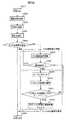
第7図は空燃比制御のフローチャートである。
第8図は第6図のフローチャートにおけるNOx量推算部分である。
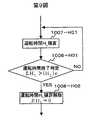
第9図は第6図のフローチャートにおけるNOx量推算部分である。
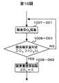
第10図は第6図のフローチャートにおけるNOx量推算部分である。
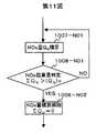
第11図は第6図のフローチャートにおけるNOx量推算部分である。
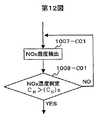
第12図は第6図のフローチャートにおけるNOx量推算部分である。
第13図は本発明のディーゼルエンジン排気ガス浄化装置の一実施形態を示す概略図である。FIG. 1 is a schematic view showing an embodiment of a diesel engine exhaust gas purification apparatus of the present invention.
FIG. 2 is a schematic view showing an embodiment of the diesel engine exhaust gas purification apparatus of the present invention.
FIG. 3 is a schematic view showing an embodiment of the diesel engine exhaust gas purification apparatus of the present invention.
FIG. 4 is a schematic view showing an embodiment of a diesel engine exhaust gas purification apparatus of the present invention.
FIG. 5 is a schematic view showing an embodiment of the diesel engine exhaust gas purification apparatus of the present invention.
FIG. 6 is a block diagram showing an air-fuel ratio control method.
FIG. 7 is a flowchart of air-fuel ratio control.
FIG. 8 is a NOx amount estimating portion in the flowchart of FIG.
FIG. 9 is a NOx amount estimating portion in the flowchart of FIG.
FIG. 10 is a NOx amount estimating portion in the flowchart of FIG.
FIG. 11 is a NOx amount estimating portion in the flowchart of FIG.
FIG. 12 is a NOx amount estimating portion in the flowchart of FIG.
FIG. 13 is a schematic view showing an embodiment of the diesel engine exhaust gas purification apparatus of the present invention.
以下、図面及び表により本発明の実施形態について説明する。
本発明のディーゼルエンジン排気ガス浄化装置はディーゼルエンジン排気ガス流路の途中に、排気ガス流路の上流からNOx選択還元能及び水素製造機能を併せ持つ触媒、リーンNOx触媒が上記の順番で配置されて成る。
上記NOx選択還元能及び水素製造機能を併せ持つ触媒は、排ガスが還元雰囲気であるとき、排ガス中に多く含まれるCOとH2Oの水性ガスシフト反応により、H2を発生させる機能を有する。このような触媒として、貴金属(Pt,Pd,Rhなど)と、担体としてZrO2,CeO2,TiO2若しくはZrO2とCeO2を含む複合酸化物を含有している各種触媒、例えば、Pt/CeO2,Pt/セリア−ジルコニア複合酸化物,Pt/TiO2などが挙げられる。担体は、酸素吸蔵能力が高く、比表面積及び細孔容積が大きいものが望ましい。
なお、本発明の触媒において、リッチにおいて水素生成が起きること、リーンにおいて選択還元性能を有することは別途確認済み(後述)である。
上記NOx選択還元能及び水素製造機能を併せ持つ触媒の下流側に配置されるリーンNOx触媒としては、貴金属を担持したアルミナのような高比表面積の耐火性無機材料に、K,Na等のアルカリ金属、Ca,Ba等のアルカリ土類金属、Ti,Mn,Fe,Cu等の遷移金属、La,Zr,Ce等の希土類金属、又はこれらの任意の組み合わせを添加して成るハニカム状モノリス型触媒を用いることができる。
第2図に(1)NOx吸着還元型触媒のみ、(2)NOx選択還元触媒とNOx吸着還元型触媒との組み合わせ、(3)NOx選択還元能及び水素製造機能を併せ持つ触媒とNOx吸着還元型触媒との組み合わせ、の3種類の触媒の200℃でのリーン及びリッチでのNOx浄化率を示す。(1)NOx吸着還元型触媒のみではリーン性能51%,リッチ性能43%,リーン/リッチトータル性能47%であった。(2)NOx選択還元触媒との組み合わせでは、リーン性能76%,リッチ性能60%,リーン/リッチトータル性能68%で、リーン性能に25ポイントの向上が見られたが、リッチ性能は17ポイントの向上にとどまった。一方、(3)NOx選択還元能及び水素製造機能を併せ持つ触媒との組み合わせでは、リーン性能82%,リッチ性能78%,リーン/リッチトータル性能80%であった。リーン性能は29ポイント,リッチ性能は35ポイントの向上がみられ、NOx選択還元触媒との組み合わせと比較するとリッチ性能は18ポイント上回っており、これは水素製造機能によるものである。
以上のことから、本発明のNOx浄化方法によりリーン/リッチ性能を大幅に改善できることが判った。特に本発明においては、リッチを深くする(空燃比の燃料を多くする)ことにより、低温時はCO製造が進み、高温時にはNOxの内部まで還元浄化がされ、排ガスの浄化が進む。一方、リッチの深くすることにより、燃費は高くなる。
上記の例においてはリーンNOx触媒と水素製造機能触媒を別に作成して直列に配置したが、リーンNOx触媒上にNOx選択還元能及び水素製造機能を併せ持つ触媒を担持させ、二層型触媒とすることもできる。
また、NOx選択還元能及び水素製造機能を併せ持つ触媒の上流に、排ガス中のPMを酸化除去せしめるディーゼルパティキュレートフィルタ(DPF)を配置してもよい。上記フィルタ手段は、PM捕捉機能を有する。
上記フィルタとしては、例えば、セラミック焼結体,セラミックファイバ及び金属などの各種材料を使用できる。具体的には、セラミックファイバをコイル状に巻いて円筒型に成形したフィルタ,ファイバを織ったものを適当な形状に成形したフィルタ,セラミック製で上流側端部が閉塞され下流側端部が開放された排気ガス通路と、上流側端部が開放され下流側端部が閉塞された排気ガス通路とが交互に配列され、隣接する排気ガス通路間には多孔質の壁面が形成されているウォールフロー型フィルタなど、様々な形態や大きさのフィルタを使用空間に応じて適宜選択できる。Hereinafter, embodiments of the present invention will be described with reference to the drawings and tables.
In the diesel engine exhaust gas purification device of the present invention, a catalyst having both NOx selective reduction ability and hydrogen production function and a lean NOx catalyst are arranged in the above order in the middle of the diesel engine exhaust gas flow path. Become.
The catalyst having both the NOx selective reduction ability and the hydrogen production function has a function of generating H2 by a water gas shift reaction of CO and H2 O that are contained in the exhaust gas when the exhaust gas is in a reducing atmosphere. As such a catalyst, various catalysts containing a noble metal (Pt, Pd, Rh, etc.) and a composite oxide containing ZrO2 , CeO2 , TiO2 or ZrO2 and CeO2 as a support, such as Pt / CeO2 , Pt / ceria-zirconia composite oxide, Pt / TiO2 and the like can be mentioned. A carrier having a high oxygen storage capacity and a large specific surface area and pore volume is desirable.
In the catalyst of the present invention, it has been confirmed separately (to be described later) that hydrogen generation occurs richly and that the lean has selective reduction performance.
As the lean NOx catalyst arranged downstream of the catalyst having both the NOx selective reduction ability and the hydrogen production function, a refractory inorganic material having a high specific surface area such as alumina supporting a noble metal, and alkali metals such as K and Na. A honeycomb monolithic catalyst comprising an alkaline earth metal such as Ca and Ba, a transition metal such as Ti, Mn, Fe and Cu, a rare earth metal such as La, Zr and Ce, or any combination thereof. Can be used.
FIG. 2 shows (1) NOx adsorption-reduction type catalyst only, (2) NOx selective reduction catalyst and NOx adsorption-reduction type catalyst, and (3) catalyst having both NOx selective reduction ability and hydrogen production function and NOx adsorption-reduction type. The NOx purification rate in lean and rich at 200 ° C. for the three types of catalysts in combination with the catalyst is shown. (1) The NOx adsorption reduction catalyst alone had a lean performance of 51%, a rich performance of 43%, and a lean / rich total performance of 47%. (2) In combination with NOx selective reduction catalyst, lean performance was 76%,
From the above, it was found that the lean / rich performance can be greatly improved by the NOx purification method of the present invention. Particularly in the present invention, by deepening rich (increasing the fuel of the air-fuel ratio), CO production proceeds at low temperatures, and reduction purification is performed up to the inside of NOx at high temperatures, and exhaust gas purification proceeds. On the other hand, fuel consumption increases by increasing the depth.
In the above example, the lean NOx catalyst and the hydrogen production function catalyst are separately created and arranged in series. However, a catalyst having both NOx selective reduction ability and hydrogen production function is supported on the lean NOx catalyst to form a two-layer catalyst. You can also.
Further, a diesel particulate filter (DPF) that oxidizes and removes PM in exhaust gas may be disposed upstream of a catalyst having both NOx selective reduction ability and hydrogen production function. The filter means has a PM capturing function.
As said filter, various materials, such as a ceramic sintered compact, a ceramic fiber, and a metal, can be used, for example. Specifically, a filter formed by winding a ceramic fiber in a coil shape into a cylindrical shape, a filter formed by weaving a fiber into an appropriate shape, and made of ceramic, the upstream end is closed and the downstream end is open The exhaust gas passages and the exhaust gas passages whose upstream end portions are open and whose downstream end portions are closed are alternately arranged, and a porous wall is formed between the adjacent exhaust gas passages. Filters of various forms and sizes, such as a flow filter, can be selected as appropriate according to the usage space.
本発明のディーゼルエンジン排気ガス浄化装置の一実施形態を第3図に示す。
本実施形態のディーゼルエンジン排気ガス浄化装置は、ディーゼルエンジシ1,エアフローセンサ6,スロットルバルブ7等を擁する吸気系、NOx吸着還元型触媒5,排気ガス流路2の触媒5より上流側に設置されたNOx選択還元能及び水素製造機能を併せ持つ触媒3,A/Fセンサ(若しくは酸素濃度センサ)8及び10,排気温度センサ9及び11等を擁する排気系及び制御ユニット(ECU)12等から構成される。ECUは入出力インターフェイスとしてのI/O LSI,演算処理装置MPU,多数の制御プログラムを記憶させた記憶装置RAMおよびROM,タイマーカウンター等より構成される。
本実施形態のディーゼルエンジン排気ガス浄化装置では、ディーゼルエンジン1から排出された排気ガスは、まずNOx選択還元能及び水素製造機能を併せ持つ触媒3に流入する。NOx選択還元能及び水素製造機能を併せ持つ触媒3はリーン運転時には高濃度のO2存在下でのNOxとCOによるNOx選択還元反応によりNOxを還元・浄化し、リッチ運転時にはCOとH2Oの水性ガスシフト反応によりH2を発生し、発生したH2がNOx吸着還元型触媒5のNOx還元反応を促進させる。
NOx吸着還元型触媒5はリーン運転時にNOをNO2に酸化した後化学吸着し、吸着されたNO2がNOx吸着還元型触媒5のNO2平衡吸着量に達する以前に排気ガスを還元雰囲気とし、吸着NO2を窒素(N2)に還元,浄化する。
また、排気ガスを還元雰囲気にする手段としては、炭化水素濃度を増大させる手段(エンジンの燃料二次噴射等),酸素濃度を低減させる手段(吸気絞り等)等があるが、これらを同期させて行った。また、上記炭化水素濃度を増大させる処理及び酸素濃度を低減させる処理時には上記NOx吸着還元型触媒5の触媒温度を250℃から500℃に制御した。これは、上記範囲の温度で、NOx吸着還元型触媒5のNOx浄化能がよいためである。An embodiment of the diesel engine exhaust gas purification apparatus of the present invention is shown in FIG.
The diesel engine exhaust gas purification apparatus of the present embodiment is installed upstream of the intake system having the
In the diesel engine exhaust gas purification apparatus of the present embodiment, the exhaust gas discharged from the
NOx adsorption-
In addition, as means for bringing the exhaust gas into a reducing atmosphere, there are means for increasing the hydrocarbon concentration (engine secondary fuel injection, etc.), means for reducing the oxygen concentration (intake throttle, etc.), etc., which are synchronized. I went. Further, during the treatment for increasing the hydrocarbon concentration and the treatment for reducing the oxygen concentration, the catalyst temperature of the NOx
本発明のディーゼルエンジン排気ガス浄化装置の一実施形態を第4図に示す。第4図は、第3図のNOx吸着還元型触媒5を吸収還元型触媒に変更したものである。
NOx吸蔵還元型触媒13はリーン運転時にNOをNO2に酸化した後吸蔵材と化学反応を起こすことで吸蔵材の硝酸塩を生成し、吸蔵されたNOxがNOx吸蔵還元型触媒13のNOx平衡吸蔵量に達する以前に排気ガスを還元雰囲気とし、吸蔵硝酸塩を窒素(N2)に還元,浄化する。吸着還元型触媒5の場合と同様に、触媒温度を250℃から500℃に制御すると、NOx吸蔵還元型触媒13のNOx浄化能がよい。One embodiment of the diesel engine exhaust gas purification apparatus of the present invention is shown in FIG. FIG. 4 is obtained by changing the NOx
The NOx occlusion reduction type catalyst 13 oxidizes NO to NO2 during lean operation and then generates a nitrate of the occlusion material by causing a chemical reaction with the occlusion material, and the occluded NOx is stored in the NOx equilibrium occlusion of the NOx occlusion reduction type catalyst 13. Before reaching the amount, the exhaust gas is reduced to a reducing atmosphere, and the stored nitrate is reduced and purified to nitrogen (N2 ). Similarly to the case of the
本発明のディーゼルエンジン排気ガス浄化装置の一実施形態を第5図に示す。第5図は、第3図の触媒3,触媒5を二層型触媒14とする例である。
二層型触媒14はNOx吸着還元型触媒上にNOx選択還元能及び水素製造機能を併せ持つ触媒を担持させたものである。排気ガス流路4の上流側からNOx選択還元能及び水素製造機能を併せ持つ触媒、NOx吸着還元型触媒の順に配置されている。An embodiment of the diesel engine exhaust gas purification apparatus of the present invention is shown in FIG. FIG. 5 shows an example in which the
The two-layer catalyst 14 is a catalyst in which a catalyst having both NOx selective reduction ability and hydrogen production function is supported on a NOx adsorption reduction catalyst. From the upstream side of the exhaust
(空燃比制御方法)
実施例1から3においてエンジンに供給される混合気の燃料濃度(以下空燃比)は次の様に制御することができる。
第6図に空燃比制御方法をブロック線図で示した。アクセルペダルの踏み込みに応じた信号を出力する負荷センサ出力,エアフローセンサにより計量された吸気量の出力信号,クランク角センサにより検出されるエンジン回転数信号,排ガス温度信号,スロットル開度を検出するスロットルポジションセンサ信号,エンジン冷却水温信号,スタータ信号等の情報からECU14は空燃比(A/F)を決定し、さらにこの信号はA/Fセンサ(若しくは酸素センサ)からフィードバックされる信号に基づき補正され、燃料噴射量を決定する。なお、低温時,アイドル時,高負荷時等では各センサ及びスイッチの信号によりフィードバック制御を停止する。また、空燃比補正学習機能により空燃比の微妙な変化や急な変化にも正確に対応できるよう空燃比補正学習機能で対応する。
決定された空燃比が還元雰囲気のときECUの指示によりインジェクタの噴射条件が決定されリッチ運転が行われる。一方、リーン運転が決定された場合、リーンNOx触媒のNOx捕捉能の有無の判定を行い捕捉能が所定の規定値(例えば、平衡捕捉量の50%)以上であると判定された場合に指示通りのリーン運転を行うべく燃料噴射量が決定され、吸着能が所定の規定値未満であると判定された場合には空燃比を所定期間リッチシフトしてリーンNOx触媒を再生する。
第7図に空燃比制御のフローチャートを示した。ステップ1002で各種の運転条件を指示するあるいは運転状態を検出する信号を読み込む。これらの信号に基づきステップ1003で空燃比を決定、ステップ1004では決定された空燃比を検出する。ステップ1005で決定された空燃比と理論空燃比との大小を比較する。ここでの比較対象となる理論空燃比は、正確にはリーンNOx触媒においてNOxの接触還元反応の速度が捕捉速度を上回る空燃比であり、予めリーンNOx触媒の特性を評価して決定されるもので、理論空燃比近傍の空燃比が選定される。ここで、設定空燃比≦理論空燃比の場合ステップ1006に進みリーンNOx触媒の再生操作を行うことなく指示通りの空燃比運転を行う。設定空燃比>理論空燃比の場合ステップ1007に進む。ステップ1007ではNOx捕捉量の推定演算を行う。推定演算方法については後述する。続いてステップ1008で推定NOx捕捉量が所定限界量以下であるか否かを判定する。限界捕捉量は予め実験等によりリーンNOx触媒のNOx捕捉特性を評価して、また排気ガス温度やリーンNOx触媒温度等を考慮して、排ガス中のNOxが十分に浄化できる値に設定される。NOx捕捉能がある場合にはステップ1006に進み、リーンNOx触媒の再生操作を行うことなく指示通りの空燃比運転を行う。NOx捕捉能がない場合にはステップ1009に進み、空燃比をリッチ側にシフトする。ステップ1010ではリッチシフト時間をカウントし、経過時間Trが所定の時間(Tr)cを超えればリッチシフトを終了する。
(NOx捕捉能の判定)
上記ステップ1008のNOx捕捉能の判定は次のように行うことができる。
第8図はリーン運転時の各種運転条件からNOx排出量を積算し、判定する方法である。
ステップ1007−E01で排気ガス温度等のリーンNOx触媒の作動条件に関する信号と排ガス中のNOx濃度に影響する各種の機関運転条件に関する信号とを読み込み単位時間に吸着するNOx量ENを推算する。ステップ1007−E02でENを積算し、ステップ1008−E01で積算値ΣENと捕捉量の上限値(EN)cとの大小を比較する。ΣEN≦(EN)cの場合は積算を継続し、ΣEN>(EN)cの場合ステップ1008−E02で積算を解除しステップ1009に進む。
第9図はリーン運転の積算時間より判定する方法である。ステップ1007−H01でリーン運転時間HLを積算し、ステップ1008−H01で積算値ΣHLと積算時間の上限値(HL)cとの大小を比較する。ΣHL≦(HL)cの場合積算を継続し、ΣHL>(HL)cの場合ステップ1008−H02で積算を解除しステップ1009に進む。
第10図はリーン運転時のA/Fセンサ(若しくは酸素センサ)信号より判定する方法である。ステップ1007−O01でリーン運転における酸素量Q0を積算し、ステップ1008−O01で積算値ΣQ0と積算酸素量の上限値(Q0)cとの大小を比較する。ΣQ0≦(Q0)cの場合積算を継続し、ΣQ0>(Q0)cの場合ステップ1008−O02で積算を解除しステップ1009に進む。
第11図はリーン運転時のリーンNOx触媒入口で検出したNOx濃度センサ信号より判定する方法である。ステップ1007−N01でNOx濃度センサ信号に基づきリーンNOx触媒入口におけるNOx量QNを積算する。ステップ1008−N01で積算値ΣQNと積算NOx量の上限値(QN)cとの大小を比較する。ΣQN≦(QN)cの場合積算を継続し、ΣQN>(QN)cの場合ステップ1008−N02で積算を解除しステップ1009に進む。
第12図はリーン運転時のリーンNOx触媒出口で検出したNOx濃度センサ信号より判定する方法である。ステップ1007−C01でNOx濃度センサ信号に基づきリーンNOx触媒入口におけるNOx濃度CNを検出する。ステップ1008−C01でCNをCNの上限値(QN)cとの大小を比較する。CN≦(QN)cの場合検出を継続し、CN>(QN)cの場合ステップ1009に進む。(Air-fuel ratio control method)
In the first to third embodiments, the fuel concentration (hereinafter referred to as air-fuel ratio) of the air-fuel mixture supplied to the engine can be controlled as follows.
FIG. 6 is a block diagram showing the air-fuel ratio control method. A load sensor output that outputs a signal in response to depression of the accelerator pedal, an output signal of an intake air amount measured by an air flow sensor, an engine speed signal detected by a crank angle sensor, an exhaust gas temperature signal, and a throttle that detects a throttle opening The ECU 14 determines the air-fuel ratio (A / F) from information such as the position sensor signal, engine coolant temperature signal, starter signal, etc., and this signal is corrected based on the signal fed back from the A / F sensor (or oxygen sensor). And determine the fuel injection amount. Note that feedback control is stopped by signals from the sensors and switches at low temperatures, idling, high loads, and the like. In addition, the air-fuel ratio correction learning function is used to accurately cope with subtle or sudden changes in the air-fuel ratio.
When the determined air-fuel ratio is a reducing atmosphere, the injection conditions of the injector are determined according to an instruction from the ECU, and rich operation is performed. On the other hand, when the lean operation is determined, it is determined whether or not the lean NOx catalyst has the NOx trapping ability, and the trapping ability is determined to be equal to or higher than a predetermined specified value (for example, 50% of the equilibrium trapped amount). When the fuel injection amount is determined to perform the normal lean operation and it is determined that the adsorption capacity is less than the predetermined specified value, the air-fuel ratio is rich-shifted for a predetermined period to regenerate the lean NOx catalyst.
FIG. 7 shows a flowchart of air-fuel ratio control. In
(Determination of NOx trapping ability)
The determination of the NOx trapping ability in
FIG. 8 shows a method for determining by integrating the NOx emission amount from various operating conditions during lean operation.
Step 1007-E01 to estimate the NOx amount EN adsorbed on the signal and the reading unit time for various engine operating conditions affecting the NOx concentration signal and the exhaust gas about the operating conditions of the lean NOx catalyst such as an exhaust gas temperature. Integrates theE N in step 1007-E02, compares the magnitude of the integrated value? EnN and trapping amount upper limit value(E N) c in step 1008-E01. If ΣEN ≦ (EN ) c, the integration is continued. If ΣEN > (EN ) c, the integration is canceled in step 1008-E02, and the process proceeds to step 1009.
FIG. 9 shows a method for determining from the accumulated time of lean operation. In step 1007-H01, the lean operation timeHL is integrated, and in step 1008-H01, the integrated value ΣHL and the upper limit value (HL ) c of the integrated time are compared. If ΣHL ≦ (HL ) c, the integration is continued. If ΣHL > (HL ) c, the integration is canceled in step 1008-H02 and the process proceeds to step 1009.
FIG. 10 shows a method of determining from an A / F sensor (or oxygen sensor) signal during lean operation. The amount of oxygenQ 0 is integrated in the lean operation at step 1007-O01, integrated value [sum] Q0 and the accumulated oxygen amount upper limit value at step 1008-O01(Q 0) compares the magnitude of the c. If ΣQ0 ≦ (Q0 ) c, the integration is continued. If ΣQ0 > (Q0 ) c, the integration is canceled in step 1008-O02 and the process proceeds to step 1009.
FIG. 11 shows a method of determining from the NOx concentration sensor signal detected at the lean NOx catalyst inlet during the lean operation. Integrating the NOx amountQ N in the lean NOx catalyst inlet based on the NOx concentration sensor signal in step 1007-N01. Integrated value [sum] QN and the accumulated NOx amount upper limit value at step 1008-N01 compares the magnitude of the(Q N) c. If ΣQN ≦ (QN ) c, the integration is continued. If ΣQN > (QN ) c, the integration is canceled in step 1008-N02 and the process proceeds to step 1009.
FIG. 12 shows a method of determining from the NOx concentration sensor signal detected at the lean NOx catalyst outlet during lean operation. In step 1007-C01 detects the NOx concentrationC N in the lean NOx catalyst inlet based on the NOx concentration sensor signal. TheC N in step 1008-C01 compares the magnitude of the upper limit ofC N(QN) c. If CN ≦ (QN ) c, the detection is continued. If CN > (QN ) c, the process proceeds to Step 1009.
本発明のディーゼルエンジン排気ガス浄化装置の一実施形態を第13図に示す。
本実施例は、排気ガス流路4に上流側から三元触媒15,排ガス中の粒子状物質を酸化除去せしめるディーゼルパティキュレートフィルタ16,NOx選択還元能及び水素製造機能を併せ持つ触媒3,NOx吸着還元型触媒5を配置しているものであって、各触媒に対応させたA/Fセンサ(若しくは酸素濃度センサ)8,10及び17,排気温度センサ9,11,18及び20,圧力センサ19及び21等を設置する例である。
本実施形態のディーゼルエンジン排気ガス浄化装置では、ディーゼルエンジン1から排出された排気ガスは、まず三元触媒15により熱せられ、排ガス中のHCが分解される。ディーゼルエンジン排ガス中の炭化水素は炭素数が7以上の高級炭化水素が比較的多いため、三元触媒15により分解して炭素数が6以下の低級炭化水素の割合を増大させることにより、排ガス流路下流側のNOx吸着還元型触媒5でのNOx還元反応を効率良く進行させることができる。また三元触媒15ではNOx,HC,COを若干浄化することができる。
DPF16はセラミック製ハニカム型フィルタである。DPF16内には、上流側端部が閉塞され、下流側端部が開放された排気ガス流路と、上流側端部が開放され、下流側端部が閉塞された排気ガス流路とが交互に配列され、隣接する排気ガス流路間には多孔質の壁面が形成されている(ウォールフロー型フィルタ)。DPF16に流入する排気ガスは、上流側端部が開放され下流側端部が閉塞された排気ガス流路に流入し、次に、隣接する排気ガス流路の間に設けられた多孔質の壁面から、上流側端部が閉塞され、下流側端部が開放された排気ガス流路に流入し、下流側に流出する。この過程において、ディーゼル排気ガス中のPMは壁面への衝突や吸着により捕集される。
なお、DPF16に捕集されたPMは、一定量堆積後に排気ガス温度を高めることにより燃焼除去をする。排気ガス温度を高める方法はエンジン制御,電気ヒータ、上流に配置した触媒の反応熱等のいずれでもよい。燃焼したPMの一部は不完全燃焼によりCOとなり、また未燃のHCが排出されるが、これらは下流側のNOx選択還元能及び水素製造機能を併せ持つ触媒3及びNOx吸着還元型触媒5で浄化されることになる。
以上、本発明を実施例により説明したが、本発明は上記実施例に限定されるものではなく、本発明の開示の範囲内で種々変形して実施することができる。
例えば、図示していないが、水素センサをNOx触媒の前段に設置し、所定量のH2を検知した場合にリーンとリッチの切り換えをさせることができる。One embodiment of the diesel engine exhaust gas purification apparatus of the present invention is shown in FIG.
In the present embodiment, the three-
In the diesel engine exhaust gas purification device of the present embodiment, the exhaust gas discharged from the
The
The PM collected in the
Although the present invention has been described with reference to the embodiments, the present invention is not limited to the above embodiments, and various modifications can be made within the scope of the disclosure of the present invention.
For example, although not shown, a hydrogen sensor can be installed in front of the NOx catalyst, and when a predetermined amount of H2 is detected, switching between lean and rich can be performed.
(実施例触媒1)
コージェライト製ハニカムにCeO2を含むコーティング用スラリーをコーティングした後、乾燥焼成して、ハニカムの見掛けの容積1リットルあたり190gのCeO2をコーティングした。該CeO2コートハニカムに、ジニロトロジアンミンPt硝酸溶液を含浸し200℃で乾燥、続いて600℃で焼成した。以上により、ハニカムの見掛けの容積1Lに対して、金属換算でPt:2.8gを含有する実施例触媒1を得た。
(試験例)
実施例触媒1を用いて、理論空燃比以下の運転後に残存排ガスのパージ処理を実施してエンジンを停止した場合を想定した試験を行った。試験に用いたガスは、リーンバーン排ガスを模擬したリーンモデルガスと、理論空燃比以下の燃焼を模擬したリッチモデルガスとした。
リーンモデルガスの組成は、NOx:100ppm,C3H8:500ppmC1,CO:0.1%,O2:5%,H2O:10%,N2:残部とした。
リッチモデルガスの組成は、NOx:100ppm,C3H8:500ppmC1,CO:2%,O2:0%,H2O:10%,N2:残部とした。
以下の手順で試験した。
▲1▼ 400℃にてリッチモデルガスを3分間流通させた。
▲2▼ 200℃に冷却した後、リーンモデルガスの流通を開始した。
NOx浄化率は、式1のリーンモデルガスとして供給したNOx濃度(100ppm)に対する触媒層流通前後のNOx濃度の減少率とした。定義式を式1に示した。
実施例触媒1のリーンにおけるNOx浄化率の定常値,リッチにおけるCO浄化率を第1表に示す。リーンにおけるNOx浄化率の定常値が25%であることより、リーンにおいて選択的にNOxが還元されていることは明らかである。また、リッチにおけるCO浄化率から算出した水素生成量と実施例触媒1流通後のリッチガス中の水素濃度とはほぼ一致した。以上のことから、実施例触媒1において、リッチにおいて水素生成が起きること、リーンにおいて選択還元性能を有することは明らかである。
A cordierite honeycomb was coated with a slurry for coating containing CeO2 and then dried and fired to coat 190 g of CeO2 per liter of apparent volume of the honeycomb. The CeO2 coated honeycomb was impregnated with a dinitrotrodiammine Pt nitric acid solution, dried at 200 ° C., and then fired at 600 ° C. Thus,
(Test example)
Using the catalyst of Example 1, a test was performed assuming that the engine was stopped by purging the residual exhaust gas after operation below the stoichiometric air-fuel ratio. The gas used for the test was a lean model gas simulating lean burn exhaust gas and a rich model gas simulating combustion below the stoichiometric air-fuel ratio.
The composition of the lean modelgas, NOx: 100ppm, C 3 H 8: 500ppmC1, CO: 0.1%, O 2: 5%, H 2 O: 10%, N 2: was the remainder.
The composition of the rich modelgas, NOx: 100ppm, C 3 H 8: 500ppmC1, CO: 2%, O 2: 0%, H 2 O: 10%, N 2: was the remainder.
The following procedure was used for testing.
(1) Rich model gas was circulated at 400 ° C. for 3 minutes.
(2) After cooling to 200 ° C., the distribution of lean model gas was started.
The NOx purification rate was defined as the rate of decrease of the NOx concentration before and after the catalyst bed circulation with respect to the NOx concentration (100 ppm) supplied as the lean model gas of
Table 1 shows the steady value of the NOx purification rate in the lean of
(実施例触媒2)
アルミナ粉末とアルミナの前駆体からなり硝酸酸性に調整したスラリーにMgO(平均粒径:30μm,比表面積:1m2/g)を添加したMgO−アルミナ混合スラリーをコージェライト製ハニカム(400セル/inc2)にコーティングした後、乾燥焼成して、ハニカムの見掛けの容積1リットルあたり190gのアルミナと10gのMgOをコーティングしたMgO−アルミナコートハニカムを得た。該MgO−アルミナコートハニカムに、硝酸Ce水溶解を含浸した後、200℃で乾燥、続いて600℃で焼成した。
次に、ジニロトロジアンミンPt硝酸溶液と硝酸Rhと硝酸Pdと硝酸Mnと酢酸Kと硝酸Mnの混合液を含浸し200℃で乾燥、続いて600℃で焼成した。最後に、酢酸Kと硝酸Naと硝酸Liとチタニアゾルの混合液を含浸し200℃で乾燥、続いて600℃で焼成した。
以上により、ハニカムの見掛けの容積1Lに対して、金属換算でCe:41g,Rh:0.14g,Pt:1.2g,Pd:3.0g,K:5.2g,Na:4.1g,Li:0.05g,Ti:4.3g,Mn:13.7gを含有する実施例触媒2を得た。第2表に触媒組成を示す。
アルミナ粉末とアルミナの前駆体からなり硝酸酸性に調整したスラリーをコージェライト製ハニカム(400セル/inc2)にコーティングした後、乾燥焼成して、ハニカムの見掛けの容積1リットルあたり190gのアルミナをコートしたアルミナコートハニカムを得た。該アルミナコートハニカムに、チタニアゾルを含浸した後、200℃で乾燥、続いて600℃で焼成した。
次に、ジニロトロジアンミンPt硝酸溶液と硝酸Rhの混合液を含浸し200℃で乾燥、続いて600℃で焼成した。
以上により、ハニカムの見掛けの容積1Lに対して、金属換算でTi:0.1g,Rh:0.14g,Pt:2.8gを含有する実施例触媒3を得た。
(試験例)
実施例触媒1から3を用いて、理論空燃比以下の運転後に残存排ガスのパージ処理を実施してエンジンを停止した場合を想定した試験を行った。試験に用いたガスは、リーンバーン排ガスを模擬したリーンモデルガスと、理論空燃比以下の燃焼を模擬したリッチモデルガスとした。
リーンモデルガスの組成は、NOx:100ppm,C3H8:500ppmC1,CO:0.1%,O2:5%,H2O:10%,N2:残部とした。
リッチモデルガスの組成は、NOx:100ppm,C3H8:500ppmC1,CO:2%,O2:0%,H2O:10%,N2:残部とした。
以下の手順で試験した。
▲1▼400℃にてリッチモデルガスを流通させた。
▲2▼200℃に冷却した後、リッチモデルガスを3分間流通させた後、リーンモデルガスを3分間流通させた。このリッチモデルガスとリーンモデルガスの交互に流通させる操作を18分間繰り返した。
(試験結果)
第2図に3種類の組み合わせ結果を示す。各組み合わせに使用した触媒容積は6ccとした。
(1)実施例触媒2(NOx吸着還元型触媒)のみ。
(2)実施例触媒3(NOx選択還元触媒)の後流に実施例触媒2(NOx吸着還元型触媒)を配置させた。
(3)実施例触媒3(NOx選択還元型触媒)の後流に実施例触媒1(水素製造機能を併せ持つ触媒)、さらにその後流に実施例触媒2(NOx吸着還元型触媒)を配置させた。
上記の3種類の触媒の200℃でのリーン及びリッチでのNOx浄化率を示す。
(1)NOx吸着還元型触媒のみではリーン性能51%,リッチ性能43%,リーン/リッチトータル性能47%であった。
(2)NOx選択還元触媒との組み合わせでは、リーン性能76%,リッチ性能60%,リーン/リッチトータル性能68%。(1)に対して、リーン性能に25ポイントの向上が見られたが、リッチ性能は17ポイントの向上。
(3)NOx選択還元能及び水素製造機能を併せ持つ触媒との組み合わせでは、リーン性能82%,リッチ性能78%,リーン/リッチトータル性能80%であった。(1)に対して、リーン性能は29ポイント、リッチ性能は35ポイントの向上がみられた。また、(2)に対してリッチ性能は18ポイント上回っており、これは水素製造機能によるものである。(Example catalyst 2)
A cordierite honeycomb (400 cells / inc) was prepared by mixing an MgO-alumina mixed slurry in which MgO (average particle size: 30 μm, specific surface area: 1 m2 / g) was added to a slurry made of alumina powder and an alumina precursor and adjusted to be acidic with nitric acid. After coating to2 ), it was dried and fired to obtain a MgO-alumina coated honeycomb coated with 190 g of alumina and 10 g of MgO per liter of apparent volume of the honeycomb. The MgO-alumina-coated honeycomb was impregnated with Ce nitrate solution, dried at 200 ° C., and then fired at 600 ° C.
Next, it was impregnated with a mixed solution of dinitrotrodianmine Pt nitric acid solution, nitric acid Rh, nitric acid Pd, nitric acid Mn, acetic acid K and nitric acid Mn, dried at 200 ° C. and subsequently calcined at 600 ° C. Finally, it was impregnated with a mixed solution of acetic acid K, Na nitrate, Li nitrate and titania sol, dried at 200 ° C., and subsequently fired at 600 ° C.
As described above, Ce: 41 g, Rh: 0.14 g, Pt: 1.2 g, Pd: 3.0 g, K: 5.2 g, Na: 4.1 g, in terms of metal, for an apparent volume of 1 L of the honeycomb.
A cordierite honeycomb (400 cells / inc2 ) coated with a slurry consisting of an alumina powder and an alumina precursor and adjusted to nitric acid acidity is dried and fired to coat 190 g of alumina per liter of apparent honeycomb volume. An alumina-coated honeycomb was obtained. The alumina-coated honeycomb was impregnated with titania sol, dried at 200 ° C., and then fired at 600 ° C.
Next, it was impregnated with a mixed solution of dinitrotrodianmine Pt nitric acid solution and nitric acid Rh, dried at 200 ° C., and subsequently fired at 600 ° C.
Thus,
(Test example)
The test which assumed the case where the engine was stopped by carrying out the purge process of the residual exhaust gas after the operation below the stoichiometric air-fuel ratio using the catalyst of Examples 1 to 3 was performed. The gas used for the test was a lean model gas simulating lean burn exhaust gas and a rich model gas simulating combustion below the stoichiometric air-fuel ratio.
The composition of the lean modelgas, NOx: 100ppm, C 3 H 8: 500ppmC1, CO: 0.1%, O 2: 5%, H 2 O: 10%, N 2: was the remainder.
The composition of the rich modelgas, NOx: 100ppm, C 3 H 8: 500ppmC1, CO: 2%, O 2: 0%, H 2 O: 10%, N 2: was the remainder.
The following procedure was used for testing.
(1) Rich model gas was circulated at 400 ° C.
(2) After cooling to 200 ° C., the rich model gas was allowed to flow for 3 minutes, and then the lean model gas was allowed to flow for 3 minutes. The operation of alternately flowing the rich model gas and the lean model gas was repeated for 18 minutes.
(Test results)
FIG. 2 shows three types of combination results. The catalyst volume used for each combination was 6 cc.
(1) Example catalyst 2 (NOx adsorption reduction catalyst) only.
(2) The example catalyst 2 (NOx adsorption reduction catalyst) was placed downstream of the example catalyst 3 (NOx selective reduction catalyst).
(3) Example catalyst 1 (a catalyst having a hydrogen production function) is arranged downstream of the example catalyst 3 (NOx selective reduction catalyst), and the example catalyst 2 (NOx adsorption reduction catalyst) is arranged further downstream. .
The lean and rich NOx purification rates at 200 ° C. of the above three types of catalysts are shown.
(1) The NOx adsorption reduction catalyst alone had a lean performance of 51%, a rich performance of 43%, and a lean / rich total performance of 47%.
(2) In combination with the NOx selective reduction catalyst, the lean performance is 76%, the rich performance is 60%, and the lean / rich total performance is 68%. Compared to (1), a 25 point improvement in lean performance was seen, but a rich performance improvement of 17 points.
(3) In combination with a catalyst having both NOx selective reduction ability and hydrogen production function, the lean performance was 82%, the rich performance was 78%, and the lean / rich total performance was 80%. In contrast to (1), the lean performance improved by 29 points and the rich performance improved by 35 points. In addition, the rich performance exceeds 18 points with respect to (2), which is due to the hydrogen production function.
本発明により低温でのNOx浄化性能が大幅に改善される。さらに、水素製造機能を有する触媒はNOx選択還元能も併せ持つため、リーン時のNOx浄化能も向上する。その結果、エンジンの運転状態をリッチ運転に切り換える頻度を減少させることが可能となり、燃費を向上させることができる。また、NOx選択還元触媒と水素製造触媒を直列に配置した場合と比較すると、貴金属使用量の低減,熱容量の低減,空間効率の効率を図ることができる。
また、本発明によれば、排気温度が低温であるディーゼルエンジンにおいても、排気ガス中のNOxを十分に還元浄化することができるディーゼルエンジン排気ガス浄化触媒及びこれを用いた排気ガス浄化装置を提供することができる。According to the present invention, the NOx purification performance at a low temperature is greatly improved. Furthermore, since the catalyst having a hydrogen production function also has a NOx selective reduction ability, the NOx purification ability at the time of lean is also improved. As a result, the frequency at which the engine operating state is switched to the rich operation can be reduced, and fuel consumption can be improved. Further, as compared with the case where the NOx selective reduction catalyst and the hydrogen production catalyst are arranged in series, it is possible to reduce the amount of noble metal used, the heat capacity, and the space efficiency.
Further, according to the present invention, there is provided a diesel engine exhaust gas purification catalyst capable of sufficiently reducing and purifying NOx in exhaust gas even in a diesel engine having a low exhaust temperature, and an exhaust gas purification device using the same. can do.
Claims (7)
Translated fromJapanese排気ガスの流路の前記水素製造機能及びNOx選択還元能を有する触媒の上流側にディーゼルパティキュレートフィルタが配置されていることを特徴とする排ガス浄化装置。An exhaust gas purification device according to claim 1 or 2,
An exhaust gas purification apparatus, wherein a diesel particulate filter is disposed upstream of a catalyst having the hydrogen production function and NOx selective reduction ability in an exhaust gas flow path.
排気ガスの流路の前記ディーゼルパティキュレートフィルタの上流側に三元触媒が配置されていることを特徴とする排気ガス浄化装置。An exhaust gas purification device according to claim 4,
An exhaust gas purification apparatus, wherein a three-way catalyst is disposed upstream of the diesel particulate filter in an exhaust gas flow path.
担体成分としてZrO2,CeO2,TiO2,ZrO2とCeO2を含む複合酸化物、のいずれかを用い、触媒成分としてRh,Pt,Pdから選ばれる少なくとも一種の貴金属を用いたことを特徴とする排気ガス浄化用触媒。A catalyst having a hydrogen production function and NOx selective reduction ability under lean conditions,
Any one of ZrO2 , CeO2 , TiO2 , composite oxide containing ZrO2 and CeO2 is used as a support component, and at least one noble metal selected from Rh, Pt, Pd is used as a catalyst component Exhaust gas purification catalyst.
前記水素量の積算が所定値を超えた場合にリーン運転をリッチ運転に切り換えることを特徴とする排ガス浄化システム。Exhaust gas is purified by a hydrogen production function catalyst, the exhaust gas purified by the hydrogen production function catalyst is purified by a lean NOx catalyst, and the amount of hydrogen flowing into the NOx catalyst is detected by a hydrogen sensor installed in front of the NOx catalyst. ,
An exhaust gas purification system that switches lean operation to rich operation when integration of the hydrogen amount exceeds a predetermined value.
Applications Claiming Priority (1)
| Application Number | Priority Date | Filing Date | Title |
|---|---|---|---|
| PCT/JP2005/016683WO2007029339A1 (en) | 2005-09-05 | 2005-09-05 | Exhaust gas purifying apparatus for internal combustion engine and method for exhaust gas purification |
Publications (1)
| Publication Number | Publication Date |
|---|---|
| JPWO2007029339A1true JPWO2007029339A1 (en) | 2009-03-12 |
Family
ID=37835476
Family Applications (1)
| Application Number | Title | Priority Date | Filing Date |
|---|---|---|---|
| JP2007534233APendingJPWO2007029339A1 (en) | 2005-09-05 | 2005-09-05 | Exhaust gas purification device and exhaust gas purification method for internal combustion engine |
Country Status (2)
| Country | Link |
|---|---|
| JP (1) | JPWO2007029339A1 (en) |
| WO (1) | WO2007029339A1 (en) |
Families Citing this family (3)
| Publication number | Priority date | Publication date | Assignee | Title |
|---|---|---|---|---|
| CN101970817B (en)* | 2008-02-05 | 2018-01-26 | 巴斯夫公司 | Gasoline engine emission treatment system with particulate filter |
| JP6123822B2 (en)* | 2015-02-13 | 2017-05-10 | トヨタ自動車株式会社 | Exhaust purification device deterioration diagnosis device |
| JP6551312B2 (en)* | 2016-06-02 | 2019-07-31 | 株式会社デンソー | Reductant addition control device |
Citations (6)
| Publication number | Priority date | Publication date | Assignee | Title |
|---|---|---|---|---|
| JPH04330314A (en)* | 1991-04-30 | 1992-11-18 | Isuzu Motors Ltd | Catalyst type exhaust purifying device for diesel engine |
| JP2000015101A (en)* | 1998-06-30 | 2000-01-18 | Toyota Motor Corp | Exhaust gas purification catalyst |
| JP2003314328A (en)* | 2002-02-19 | 2003-11-06 | Nissan Motor Co Ltd | Exhaust gas purification device |
| JP2004209386A (en)* | 2002-12-27 | 2004-07-29 | Valtion Teknillinen Tutkimuskeskus | Method for catalytic reduction of nitrogen oxides and catalyst therefor |
| JP2004218475A (en)* | 2003-01-10 | 2004-08-05 | Isuzu Motors Ltd | Exhaust emission control system for internal combustion engine and exhaust emission control method for internal combustion engine |
| JP2005030282A (en)* | 2003-07-10 | 2005-02-03 | Ibiden Co Ltd | Holding seal material for catalyst carrier |
- 2005
- 2005-09-05JPJP2007534233Apatent/JPWO2007029339A1/enactivePending
- 2005-09-05WOPCT/JP2005/016683patent/WO2007029339A1/enactiveApplication Filing
Patent Citations (6)
| Publication number | Priority date | Publication date | Assignee | Title |
|---|---|---|---|---|
| JPH04330314A (en)* | 1991-04-30 | 1992-11-18 | Isuzu Motors Ltd | Catalyst type exhaust purifying device for diesel engine |
| JP2000015101A (en)* | 1998-06-30 | 2000-01-18 | Toyota Motor Corp | Exhaust gas purification catalyst |
| JP2003314328A (en)* | 2002-02-19 | 2003-11-06 | Nissan Motor Co Ltd | Exhaust gas purification device |
| JP2004209386A (en)* | 2002-12-27 | 2004-07-29 | Valtion Teknillinen Tutkimuskeskus | Method for catalytic reduction of nitrogen oxides and catalyst therefor |
| JP2004218475A (en)* | 2003-01-10 | 2004-08-05 | Isuzu Motors Ltd | Exhaust emission control system for internal combustion engine and exhaust emission control method for internal combustion engine |
| JP2005030282A (en)* | 2003-07-10 | 2005-02-03 | Ibiden Co Ltd | Holding seal material for catalyst carrier |
Also Published As
| Publication number | Publication date |
|---|---|
| WO2007029339A1 (en) | 2007-03-15 |
Similar Documents
| Publication | Publication Date | Title |
|---|---|---|
| CN101784763B (en) | Exhaust purification system and exhaust purification method | |
| CN102834596B (en) | The method of nitrous oxide is lowered in the exhaust aftertreatment of lean-burn engines | |
| JP4417878B2 (en) | Exhaust gas purification method and exhaust gas purification system | |
| JP2009092076A (en) | Diesel engine exhaust gas purification system | |
| US7735313B2 (en) | Method of raising temperature in exhaust-gas purifier and exhaust-gas purification system | |
| JP5429286B2 (en) | Exhaust gas purification device for internal combustion engine | |
| JP4263711B2 (en) | Exhaust gas purification device for internal combustion engine | |
| JP2012503735A (en) | Preparation method for catalytic converter for exhaust gas aftertreatment with multiple nitrogen oxide storage catalytic converters | |
| WO2006027903A1 (en) | Method of exhaust gas purification and exhaust gas purification system | |
| JP2013503284A (en) | Exhaust gas aftertreatment system with catalytically active wall flow filter with storage function upstream of a catalytic converter with the same storage function | |
| WO2007055160A1 (en) | Exhaust gas purifier for internal combustion engine | |
| CN112867562B (en) | Exhaust gas purification system for gasoline engine | |
| JP2007255342A (en) | METHOD OF CONTROLLING NOx EMISSION CONTROL SYSTEM AND NOx EMISSION CONTROL SYSTEM | |
| CN102575545B (en) | Exhaust purification device for internal combustion engines | |
| JP3885813B2 (en) | Method for raising temperature of exhaust gas purification device and exhaust gas purification system | |
| JP4582806B2 (en) | Exhaust gas purification device | |
| JP5481931B2 (en) | Exhaust purification device and exhaust purification method | |
| WO2014128860A1 (en) | Exhaust purification device of internal combustion engine | |
| JP3746179B2 (en) | Exhaust gas purification device for internal combustion engine | |
| JP4736724B2 (en) | Exhaust gas purification device for internal combustion engine | |
| JP3885814B2 (en) | Method for raising temperature of exhaust gas purification device and exhaust gas purification system | |
| JPWO2007029339A1 (en) | Exhaust gas purification device and exhaust gas purification method for internal combustion engine | |
| JP5332664B2 (en) | Engine exhaust purification system | |
| JP2006226190A (en) | Controller of lean burn engine | |
| JP3896224B2 (en) | Control device for internal combustion engine |
Legal Events
| Date | Code | Title | Description |
|---|---|---|---|
| A131 | Notification of reasons for refusal | Free format text:JAPANESE INTERMEDIATE CODE: A131 Effective date:20110222 | |
| A02 | Decision of refusal | Free format text:JAPANESE INTERMEDIATE CODE: A02 Effective date:20111025 |