JPWO2006090894A1 - Communication system, server, terminal, and communication control program - Google Patents
Communication system, server, terminal, and communication control programDownload PDFInfo
- Publication number
- JPWO2006090894A1 JPWO2006090894A1JP2007504839AJP2007504839AJPWO2006090894A1JP WO2006090894 A1JPWO2006090894 A1JP WO2006090894A1JP 2007504839 AJP2007504839 AJP 2007504839AJP 2007504839 AJP2007504839 AJP 2007504839AJP WO2006090894 A1JPWO2006090894 A1JP WO2006090894A1
- Authority
- JP
- Japan
- Prior art keywords
- communication
- specific user
- communication terminal
- terminal
- position information
- Prior art date
- Legal status (The legal status is an assumption and is not a legal conclusion. Google has not performed a legal analysis and makes no representation as to the accuracy of the status listed.)
- Withdrawn
Links
- 238000004891communicationMethods0.000titleclaimsabstractdescription617
- 238000001514detection methodMethods0.000claimsdescription46
- 238000000034methodMethods0.000claimsdescription30
- 238000012545processingMethods0.000claimsdescription12
- 230000004044responseEffects0.000description59
- 230000006870functionEffects0.000description58
- 238000010586diagramMethods0.000description20
- 238000009434installationMethods0.000description18
- 230000008520organizationEffects0.000description8
- 230000005540biological transmissionEffects0.000description7
- 230000008569processEffects0.000description7
- 239000004065semiconductorSubstances0.000description5
- 230000005684electric fieldEffects0.000description3
- 238000012546transferMethods0.000description3
- 125000002066L-histidyl groupChemical group[H]N1C([H])=NC(C([H])([H])[C@](C(=O)[*])([H])N([H])[H])=C1[H]0.000description2
- 230000004913activationEffects0.000description2
- 239000004973liquid crystal related substanceSubstances0.000description2
- 230000008901benefitEffects0.000description1
- 238000007796conventional methodMethods0.000description1
- 238000012986modificationMethods0.000description1
- 230000004048modificationEffects0.000description1
- 239000007787solidSubstances0.000description1
Images


Classifications
- H—ELECTRICITY
- H04—ELECTRIC COMMUNICATION TECHNIQUE
- H04W—WIRELESS COMMUNICATION NETWORKS
- H04W4/00—Services specially adapted for wireless communication networks; Facilities therefor
- H—ELECTRICITY
- H04—ELECTRIC COMMUNICATION TECHNIQUE
- H04M—TELEPHONIC COMMUNICATION
- H04M3/00—Automatic or semi-automatic exchanges
- H04M3/42—Systems providing special services or facilities to subscribers
- H04M3/487—Arrangements for providing information services, e.g. recorded voice services or time announcements
- H04M3/493—Interactive information services, e.g. directory enquiries ; Arrangements therefor, e.g. interactive voice response [IVR] systems or voice portals
- H04M3/4931—Directory assistance systems
- H—ELECTRICITY
- H04—ELECTRIC COMMUNICATION TECHNIQUE
- H04M—TELEPHONIC COMMUNICATION
- H04M2203/00—Aspects of automatic or semi-automatic exchanges
- H04M2203/20—Aspects of automatic or semi-automatic exchanges related to features of supplementary services
- H04M2203/2094—Proximity
- H—ELECTRICITY
- H04—ELECTRIC COMMUNICATION TECHNIQUE
- H04M—TELEPHONIC COMMUNICATION
- H04M2207/00—Type of exchange or network, i.e. telephonic medium, in which the telephonic communication takes place
- H04M2207/18—Type of exchange or network, i.e. telephonic medium, in which the telephonic communication takes place wireless networks
Landscapes
- Engineering & Computer Science (AREA)
- Signal Processing (AREA)
- Computer Networks & Wireless Communication (AREA)
- Telephonic Communication Services (AREA)
- Mobile Radio Communication Systems (AREA)
Abstract
Translated fromJapaneseDescription
Translated fromJapanese本発明は通信システムに関し、特に、移動中の着呼側ユーザを呼出し、着呼側ユーザが通信端末を使用して発呼側ユーザとの間でマルチメディアコミュニケーションを行うことのできる通信システム、サーバ、端末及び通信制御プログラムに関する。 TECHNICAL FIELD The present invention relates to a communication system, and more particularly, a communication system and a server capable of calling a called user on the move and allowing the called user to perform multimedia communication with the calling user using a communication terminal. The present invention relates to a terminal and a communication control program.
マルチメディア通信の普及と高度化により、外出先又は移動先であっても、ノートPC(Personal Computer)、PDA(Personal Digital Assistance)、携帯電話などの移動端末、あるいはリモートオフィスやホットスポットなどの環境を利用してネットワークに接続することが可能となっている。
また、オフィス移転などを機にネットワークを再構築し、新しいオフィススタイルが導入され始めている。新しいオフィススタイルでは、広帯域無線LANを使用し、好きな場所で通信端末を使用して業務を行う、フリーデスク制のユビキタスオフィスが注目を集めている。
このような環境下でユーザが別のユーザにマルチメディアコミュニケーションを行う場合、発呼側ユーザ(以下では、発呼者と略す)は端末から着呼側ユーザ(以下では、着呼者と略す)に向けて通信呼出をすることになる。しかしながら、着呼者の連絡先が通信システムに対して通知されていない場合には、発呼者は通信接続をすることはできないという問題がある。特に、着呼者が移動中の場合には、発呼者から通信接続をすることはより困難になる。
このような従来の通信システムの例が、例えば特開平05−207545号公報(文献1)、特開平07−50723号公報(文献2)、特開2004−153352号公報(文献3)及び特開2000−049901号公報(文献4)に記載されている。
文献1に開示される方法は、非常電話システムにおける無線端末の着信制御に関するものである。対象とするシステムは緊急連絡システムであり、構内を複数の警備員が巡回しており、緊急事態が発生すると、発生現場の付近にいる警備員の無線端末を呼出して、現場に急行させる。
文献1の方法では、無線端末から常に手動又は自動で周期的に端末識別子を含む位置事前登録情報を送信し、位置事前登録情報は中央制御装置に無線端末の位置情報として記憶される。緊急事態発生時は、無線端末の位置情報をもとに現場付近の警備員の無線端末を呼出し、現場に急行させるというものである。
また、文献2の方法は、マルチゾーン方式のコードレス電話システムに関するものである。電子交換機による内線サービスはコード付き内線電話を固定して使用していることを前提としたものであり、電話器を携帯する場合には、緊急の場合に連絡がとれないため、これを以下のように解決するものである。
文献2の方法では、コードレス電話器の携帯者と至急連絡をとりたいが連絡をとれない場合に、移動局が所属する呼出エリア内のコード付き内線電話器へ着信呼を転送し、コードレス電話器の携帯者への着信通知を第三者により行うというものである。
また、文献3は、サーバによりメディアの使用状況を着信者が利用可能な端末ごとに管理する。これにより、複数の端末を使い分ける着信者へ発信する際に、サーバで管理されている端末の優先度と、端末のプレゼンス(使用中のメディアがあるかどうかを確認する)をもとに、適した端末を選択することができるというものである。
また、文献4は、サーバにて、着信者が利用可能なコミュニケーションツールごとに、ツールの利用状況を管理する。これにより、事前にサーバから、着呼者が利用中のツールの情報を取得し、適切なコミュニケーションツールを選択することができるというものである。
文献1 特開平05−207545号公報
文献2 特開平07−50723号公報
文献3 特開2004−153352号公報
文献4 特開2000−049901号公報
上述した従来の技術は、いずれも以下に述べるような問題点があった。
文献1の方法は着呼者の位置を特定することを目的としており、本発明で目的とする、移動中の着呼者を呼出し、着呼者が通信サービスを提供する事業者の通信端末を使用して発呼者との間でマルチメディアコミュニケーションを行うこととは異なるものである。
また、文献1の方法は、本発明の対象とする、移動する着呼者が必要とする、マルチメディアコミュニケーションのできる適切な通信端末の位置を着呼者に示す方法を提供するものではなかった。
次に、文献2の方法は、コードレス電話器の携帯者へ連絡がとれない場合であっても、コード付き内線電話器へ着信呼を転送し、応答者がコードレス電話器の携帯者へ連絡するというものであるが、通信端末から受信者に向けて直接通信接続をすることを可能とするものではない。
また、文献3の方法は、着信者の端末に接続できる場合の方法であって、着信者の接続先が通信システムに対して通知されていない場合の接続方法を提供するものではない。
文献4の方法も、ツールの利用状況を管理する方法であって、着信者の接続先が通信システムに対して通知されていない場合の接続方法を提供するものではない。
本発明の目的は、上記従来技術の欠点を解決し、移動中の着呼者を呼出し、着呼者が通信端末を使用して発呼者との間でマルチメディアコミュニケーションを行うことを可能とする通信システム、サーバ、端末及び通信制御プログラムを提供することにある。Due to the spread and sophistication of multimedia communications, mobile terminals such as notebook PCs (Personal Computer Assistance), PDAs (Personal Digital Assistance), mobile phones, remote offices and hotspots, even when they are away from home or on the road It is possible to connect to the network using.
In addition, a new office style has begun to be introduced by restructuring the network in response to office relocation. In the new office style, a free desk system ubiquitous office that uses a broadband wireless LAN and uses a communication terminal at a favorite place is attracting attention.
In such an environment, when a user performs multimedia communication with another user, the calling user (hereinafter abbreviated as the calling party) is called from the terminal to the called user (hereinafter abbreviated as the called party). A communication call will be made for. However, if the callee's contact information is not notified to the communication system, there is a problem that the caller cannot make a communication connection. In particular, when the called party is moving, it becomes more difficult to establish a communication connection from the calling party.
Examples of such conventional communication systems include, for example, Japanese Patent Application Laid-Open No. 05-207545 (Reference 1), Japanese Patent Application Laid-Open No. 07-50723 (Reference 2), Japanese Patent Application Laid-Open No. 2004-153352 (Reference 3), and Japanese Patent Application Laid-Open No. 2004-153352. It is described in 2000-049901 (reference 4).
The method disclosed in
In the method of
The method of Document 2 relates to a multi-zone cordless telephone system. The extension service by electronic exchange is based on the premise that a corded extension telephone is used in a fixed manner. If you carry a telephone, you cannot contact in the event of an emergency. It is something to solve.
In the method of Document 2, when it is desired to make an urgent contact with a cordless telephone carrier but cannot be contacted, the incoming call is transferred to a corded extension telephone in the calling area to which the mobile station belongs. The third party is notified of the incoming call to the carrier.
Document 4 manages the usage status of the tool for each communication tool that can be used by the recipient at the server. As a result, information on the tool being used by the called party can be acquired from the server in advance, and an appropriate communication tool can be selected.
The method of
Further, the method of
Next, the method of Document 2 transfers the incoming call to the corded extension telephone even if the cordless telephone handset cannot be contacted, and the responder contacts the cordless telephone handset. However, it does not enable a direct communication connection from the communication terminal to the receiver.
The method of
The method of Document 4 is also a method for managing the usage status of the tool, and does not provide a connection method when the connection destination of the called party is not notified to the communication system.
An object of the present invention is to solve the above-mentioned drawbacks of the prior art, call a called party on the move, and allow the called party to perform multimedia communication with the calling party using a communication terminal. A communication system, a server, a terminal, and a communication control program are provided.
上記目的を達成するための本発明は、移動端末を所持する特定ユーザとの通信を要求する特定の通信端末が、複数の通信端末のうち、特定のユーザが利用可能な通信端末の位置を特定する位置情報を、特定ユーザの移動端末に対して通知することを特徴とする。
これにより、移動端末を所持する特定ユーザとの間で、移動端末の性能に制限されないデータ通信を行うことが可能となる。すなわち、移動中の着呼者を呼出し、着呼者が通信端末を使用して発呼者との間でマルチメディアコミュニケーションを行うことが可能となる。
本発明は通信システムに関し、特に、移動中の着呼者を呼出し、着呼者が通信サービスを提供する事業者の通信端末を使用して発呼者との間でマルチメディアコミュニケーションを行うことのできる通信システムを実現するものである。
本発明によれば、移動中の着呼者の呼出要求が発呼者からなされると、着呼者に対して着呼者の使用する通信端末の情報が提供され、当該通信端末を使用することにより着呼者は発呼者とマルチメディアコミュニケーションを行うことが可能となるものである。以下に概略を説明する。
最初に、発呼者は、通信端末から着呼者の呼出要求の通信を制御するサーバに送信する。サーバでは着呼者が登録されていることを確認すると、着呼者の携帯する移動端末の位置情報を検索する。移動端末の位置情報は、位置情報提供サーバからサーバへ提供される。着呼者は移動端末を常に携帯しているため、移動端末の位置と着呼者の位置は一致している。
移動端末は、着呼者が連絡を受けられるようにするために、通話機能やメール機能を備えているが、大容量の映像、画像や音声を用いるマルチメディアコミュニケーションの機能は備えていない。また、メール機能以外に着信を知らせるための振動機能又は音声機能などを備える。
サーバでは端末の位置情報を取得すると、端末の付近に位置する事業者の通信端末を確認し、着呼者の付近に事業者の通信端末がある場合に、着呼者の端末へ応答依頼を送信する。着呼者は、応答依頼に対する応答結果をサーバへ送信する。
サーバでは、着呼者が応答を承諾したことを確認すると、着呼者の使用する通信端末へマルチメディアコミュニケーションを起動するメッセージを送信する。
一方、呼出結果を待っている発呼者に対して、サーバは着呼者の呼出に成功したことを示す応答結果を、発呼者の通信端末に送信する。
以上により、発呼者の通信端末と着呼者の使用する通信端末との間で、大容量の映像、画像や音声を用いるマルチメディアによるコミュニケーションを行うことができるものである。
本発明によれば、移動端末を所持する特定ユーザとの間で、移動端末の性能に制限されないデータ通信を行うことが可能となる。
その理由は、移動端末を所持する特定ユーザとの通信を要求する特定の前記通信端末が、前記複数の通信端末のうち、前記特定のユーザが利用可能な前記通信端末の位置を特定する位置情報を、前記特定ユーザの移動端末に対して通知するからである。In order to achieve the above object, the present invention provides a specific communication terminal that requests communication with a specific user possessing a mobile terminal, and specifies a position of the communication terminal that can be used by the specific user among a plurality of communication terminals. The location information to be transmitted is notified to the mobile terminal of the specific user.
Thereby, it is possible to perform data communication with a specific user possessing the mobile terminal without being limited by the performance of the mobile terminal. That is, it is possible to call a moving called party and perform a multimedia communication with the calling party using the communication terminal.
The present invention relates to a communication system, and more particularly, to call a moving called party and to perform multimedia communication with the calling party by using the communication terminal of the provider that provides the communication service. The communication system which can be realized is realized.
According to the present invention, when a call request is made by a caller who is moving, information on a communication terminal used by the caller is provided to the caller, and the communication terminal is used. As a result, the called party can perform multimedia communication with the calling party. The outline will be described below.
Initially, the caller transmits from the communication terminal to a server that controls communication of the caller's call request. When the server confirms that the called party is registered, the server searches the location information of the mobile terminal carried by the called party. The location information of the mobile terminal is provided from the location information providing server to the server. Since the called party always carries the mobile terminal, the position of the mobile terminal matches the position of the called party.
The mobile terminal is provided with a call function and a mail function so that the called party can be contacted, but does not have a multimedia communication function using large-capacity video, images and sounds. In addition to the mail function, a vibration function or a voice function for notifying an incoming call is provided.
When the server obtains the location information of the terminal, the server confirms the communication terminal of the operator located near the terminal, and if there is a communication terminal of the operator near the called party, the server requests a response to the called party's terminal. Send. The called party transmits a response result to the response request to the server.
When the server confirms that the callee has accepted the response, the server transmits a message for starting multimedia communication to the communication terminal used by the callee.
On the other hand, for the caller waiting for the call result, the server transmits a response result indicating that the caller has been successfully called to the caller's communication terminal.
As described above, multimedia communication using large-capacity video, images, and audio can be performed between the communication terminal of the calling party and the communication terminal used by the called party.
ADVANTAGE OF THE INVENTION According to this invention, it becomes possible to perform the data communication which is not restrict | limited by the performance of a mobile terminal between the specific users who possess a mobile terminal.
The reason is that the specific communication terminal that requests communication with a specific user possessing a mobile terminal specifies position information of the communication terminal that can be used by the specific user among the plurality of communication terminals. This is because the mobile terminal of the specific user is notified.
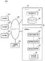
図1は、本発明の第1の実施の形態による通信システムの構成を示すブロック図である。
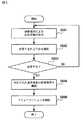
図2は、本発明の第1の実施の形態による通信システムの概略動作を説明するためのフローチャートである。
図3は、本発明の第1の実施の形態による発呼者の操作を説明するためのフローチャートである。
図4は、本発明の第1の実施の形態による通信端末を呼出制御する動作を説明するためのフローチャートである。
図5は、本発明の第1の実施の形態による着呼者の操作を説明するためのフローチャートである。
図6は、本発明の第2の実施の形態による通信システムの構成を示すブロック図である。
図7は、本発明の第2の実施の形態による通信端末を呼出制御する動作を説明するためのフローチャートである。
図8は、本発明の第1の実施例による通信システムの構成を示すブロック図である。
図9は、本発明の第1の実施例によるデータベースに格納された通信端末識別情報の一例を示す図である。
図10は、本発明の第1の実施例によるデータベースに格納されたIP電話機識別情報の一例を示す図である。
図11は、本発明の第1の実施例によるデータベースに格納された検索ポリシー情報の一例を示す図である。
図12は、本発明の第1の実施例による発呼者が着呼者を呼出すまでの通信システムの動作を説明するためのフローチャートである。
図13は、本発明の第1の実施例による呼出条件を設定する画面の一例を示す図である。
図14は、本発明の第1の実施例によるIP電話機の画面に表示される応答依頼の一例である。
図15は、本発明の第2の実施例による通信システムの構成を示すブロック図である。
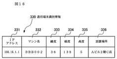
図16は、本発明の第2の実施例によるデータベースに格納された通信端末識別情報の一例を示す図である。
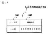
図17は、本発明の第2の実施例によるデータベースに格納された携帯電話機識別情報の一例を示す図である。
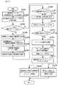
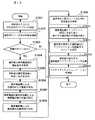
図18は、本発明の第2の実施例による発呼者が着呼者を呼出すまでの通信システムの動作を説明するためのフローチャートである。
10、20、30、40:サーバ、50、60:移動端末、100:ネットワーク、101:呼出管理手段、102:位置状況検知手段、103:着信端末検索手段、104:着信端末制御手段、105、107:データベース、106、211、221、226、271:ネットワークカード、110、120、121、210、220、225、270:通信端末、140、150、160:位置情報提供サーバ、161:通信装置、162:位置情報検索装置、212、222、227:アプリケーションプログラム、230:IP電話機、231、261、281:通信装置、232:位置情報発信装置、250:LAN、260:携帯電話機、262:携帯電話機位置特定装置、272:アプリケーションプログラム、280:基地局、282:基地局位置情報発信装置、290:インターネット、295:イントラネット、300、330:通信端末識別情報、301、331:IPアドレス、302、332:マシン名、303、333:緯度、304、334:経度、305、335:高度、306、336:設置場所、310:IP電話機識別情報、311、341:ユーザ名、312、342:電話番号、320:検索ポリシー情報、321:検索条件、322:検索範囲、340:携帯電話機識別情報、400:呼出条件設定画面、500:応答依頼画面FIG. 1 is a block diagram showing a configuration of a communication system according to the first embodiment of the present invention.
FIG. 2 is a flowchart for explaining a schematic operation of the communication system according to the first exemplary embodiment of the present invention.
FIG. 3 is a flowchart for explaining a caller's operation according to the first embodiment of the present invention.
FIG. 4 is a flowchart for explaining the operation for controlling the call of the communication terminal according to the first embodiment of the present invention.
FIG. 5 is a flowchart for explaining the operation of the called party according to the first embodiment of the present invention.
FIG. 6 is a block diagram showing a configuration of a communication system according to the second exemplary embodiment of the present invention.
FIG. 7 is a flowchart for explaining the operation for controlling the call of the communication terminal according to the second embodiment of the present invention.
FIG. 8 is a block diagram showing a configuration of a communication system according to the first exemplary embodiment of the present invention.
FIG. 9 is a diagram showing an example of communication terminal identification information stored in the database according to the first embodiment of the present invention.
FIG. 10 is a diagram showing an example of IP telephone identification information stored in the database according to the first embodiment of the present invention.
FIG. 11 is a diagram showing an example of search policy information stored in the database according to the first embodiment of this invention.
FIG. 12 is a flowchart for explaining the operation of the communication system until the calling party calls the called party according to the first embodiment of the present invention.
FIG. 13 is a diagram showing an example of a screen for setting calling conditions according to the first embodiment of the present invention.
FIG. 14 is an example of a response request displayed on the screen of the IP telephone according to the first embodiment of the present invention.
FIG. 15 is a block diagram showing a configuration of a communication system according to the second exemplary embodiment of the present invention.
FIG. 16 is a diagram showing an example of communication terminal identification information stored in the database according to the second embodiment of the present invention.
FIG. 17 is a diagram showing an example of mobile phone identification information stored in a database according to the second embodiment of the present invention.
FIG. 18 is a flowchart for explaining the operation of the communication system until the calling party calls the called party according to the second embodiment of the present invention.
10, 20, 30, 40: server, 50, 60: mobile terminal, 100: network, 101: call management means, 102: location status detection means, 103: incoming terminal search means, 104: incoming terminal control means, 105, 107: Database, 106, 211, 221, 226, 271: Network card, 110, 120, 121, 210, 220, 225, 270: Communication terminal, 140, 150, 160: Location information providing server, 161: Communication device, 162: Location information search device, 212, 222, 227: Application program, 230: IP phone, 231, 261, 281: Communication device, 232: Location information transmission device, 250: LAN, 260: Mobile phone, 262: Mobile phone Position specifying device, 272: application program, 280: base Station, 282: base station position information transmission device, 290: Internet, 295: intranet, 300, 330: communication terminal identification information, 301, 331: IP address, 302, 332: machine name, 303, 333: latitude, 304, 334: Longitude, 305, 335: Altitude, 306, 336: Installation location, 310: IP phone identification information, 311, 341: User name, 312, 342: Telephone number, 320: Search policy information, 321: Search condition, 322 : Search range, 340: Mobile phone identification information, 400: Calling condition setting screen, 500: Response request screen
以下、本発明を実施するための最良の形態について説明する。
(第1の実施の形態)
以下、本発明の第1の実施の形態について図面を参照して説明する。
図1は、本実施の形態による通信システムの構成を示すブロック図である。
図1を参照すると、本実施の形態による通信システムは、サーバ10と、通信端末110と、通信端末120、121と、移動端末50と、位置情報提供サーバ140による構成となっている。サーバ10と、通信端末110と、通信端末120、121と、移動端末50と、位置情報提供サーバ140は、ネットワーク100を介して互いに接続されている。
本実施の形態による通信システムは、映像,画像,音声などを含むマルチメディアデータを用いた通信機能に対応する。
また、本実施の形態による通信システムは、発呼者の通信端末から移動中の着呼者が所持する移動端末50への呼出要求がなされると、着呼者が利用可能な通信端末を検索し、発呼者と着呼者間の通信端末を介したマルチメディアコミュニケーションを実現するシステムである。また、ネットワーク100は、1種類又は複数種類の通信回線からなる。
本発明では、発呼者と着呼者の間で行われるマルチメディアコミュニケーションはビジネス向けの文書情報及び大容量の画像情報を扱うことを前提とし、また通信端末110、120、121は固定して使用することを前提とする。したがって、通信端末110、120、121としてはデスクトップパソコン、ワークステーションなどのコンピュータが対象となる。また、ラップトップ型、ノート型、ブック型の携帯型パソコンも使用の対象とする。
なお、情報量の少ないコミュニケーションの場合であれば、通信端末はPDA又は携帯電話機であってもよい。
本実施の形態によるサーバ10は、通信の動作を制御するサーバであって、発呼者からの呼出要求を受けると、着呼者の位置を確認して、着呼者の使用できる通信端末を着呼者へ連絡することができる。
通信端末110は、マルチメディアコミュニケーションに対応した端末であり、発呼者が使用する。
通信端末120、121は、通信サービスを提供する事業者の提供する通信端末である。通信サービスを提供する事業者は通信事業者であってもよく、また通信事業者以外の通信端末を提供する事業者であってもよい。通信端末120、121はおもに公共の場所に設置されているが、ホットスポット、インターネットカフェなどの場所であってもよい。
通信サービスを提供する事業者は、本発明による発呼者と着呼者の間のマルチメディアコミュニケーションを実現するサービスを展開する事業者である。
通信端末120、121は、移動するユーザが使用できるマルチメディアコミュニケーションに対応した端末である。通信端末120、121は複数台設置されており、着呼者はその現在地の付近に設置された通信端末120、121を使用する。
移動端末50は、着呼者が常に携帯する端末である。移動端末50は、自己の端末の位置を特定し、その位置情報を位置情報提供サーバ140に提供する。移動端末50の特定する位置情報は、緯度データと経度データの組合せ又は緯度データと経度データと高度データの組合せのいずれかの組合せにより構成される。なお、移動端末50の特定する位置情報を緯度データ、経度データ及び高度データで構成する場合、高度データは、GPS(Global Positioning System)を内蔵した移動端末50で生成してもよく、又は緯度データ及び経度データを指定して地形図から読み出したものであってもよい。
移動端末50は、ICカードもしくはICタグなどと、それらを読み込むリーダと、位置情報を特定可能な装置で構成してもよい。また、移動端末50は、GPSと組合せたものであってもよい。
本実施の形態による移動端末50は、メール機能を備えている。メールが着信した際、着呼者がメールの着信を認識可能とするため、移動端末50は、振動機能又は音声機能又はブザー機能のいずれかを備える。なお、移動端末50は通話機能を備えていてもよい。
サーバ10は、呼出管理手段101と、位置状況検知手段102と、着信端末検索手段103と、着信端末制御手段104と、データベース105を備える。
呼出管理手段101は、発呼者からの呼出要求を管理する手段であって、発呼者からの呼出要求を受信すると共に、通信端末識別情報を管理することができる。呼出管理手段101では、通信端末110、120、121及び移動端末50の端末情報をデータベース105に格納する。
位置状況検知手段102は、着呼者の位置を検知する手段であって、着呼者が携帯する移動端末50の位置を検索することができる。
着信端末検索手段103は、着呼者が使用する通信端末を検索すると共に着呼者へ応答依頼を送信する手段であって、着呼者の位置の周辺にある通信端末の中から、着呼者が使用する通信端末を検索することができる。
着信端末制御手段104は、着呼者が使用する通信端末を制御する手段であって、着呼者が使用する通信端末に対して、着信の開始動作を制御することができる。
位置情報提供サーバ140は、移動端末50の位置情報を提供するサーバである。位置情報提供サーバ140は、位置状況検知手段102から移動端末50の位置の問合せを受けると、位置状況検知手段102へ移動端末50の位置情報を提供することができる。
位置情報提供サーバ140は、移動端末50からその位置情報である緯度データ及び経度データ又は緯度データ、経度データ及び高度データを取得する。
本実施の形態によるサーバ10は、サーバのみでアプリケーションを実行するサーバサイドアプリケーション又はサーバからクライアントにアプリケーションを供給する形態又は専用装置のいずれであってもよく、又はそれらの組み合わせであってよい。
また、通信端末120、121や移動端末50で使用するマルチメディアコミュニケーション用アプリケーションは、windows(R)アプリケーション又はjava(R)アプレット又はWebアプリケーションなどのいずれであってもよく、又はそれらの組合わせであってもよい。また、通信端末120、121や移動端末50は、専用装置であってもよい。
本発明の特徴である、発呼者の通信端末110から移動する着呼者の携帯する移動端末50へ呼出要求が行なわれると、位置状況検知手段102により移動端末50の位置を特定し、着信端末検索手段103により移動端末50の付近にある通信サービスを提供する事業者の通信端末120、121を検索し、着信端末制御手段104により通信端末120、121に対して、マルチメディアコミュニケーションの動作を開始するための情報を通知する機能については、コンピュータ装置の内部にそのような機能を実現するプログラムを組み込んだ回路部品を実装して実現することも可能である。しかしながら、本発明の特徴的な機能を実現するためのプログラム(アプリケーション)を記憶媒体に記憶させ、コンピュータ装置で当該プログラムを実行することで、サーバ10として機能させることもできる。
次に、本実施の形態による通信システムの概略動作を説明する。
図2は、本実施の形態による通信システムの概略動作を説明するためのフローチャートである。なお、必要に応じて図1の所要な部分を参照する。
図2を参照すると、最初に、発呼者が着呼者に通信する際、発呼者は通信端末110にて着呼者を指定することにより、サーバ10に対して呼出要求を行う(ステップS201)。
サーバ10は着呼者への呼出要求を呼出管理手段101で受信すると、着呼者が携帯する移動端末50の識別情報を検索し、該識別情報に基づき位置状況検知手段102が移動端末50の位置を、位置情報提供サーバ140に問い合わせる(ステップS202)。
なお、移動端末50の識別情報とは、例えば移動端末50の電話番号又は固体識別番号などの端末を一意に識別できる情報である。
位置情報提供サーバ140は、移動端末50から、移動端末50で特定する位置情報を取得しておき、位置状況検知手段102から問合せがあると、該当する移動端末50の特定する位置情報を送信する。
着信端末検索手段103は、位置情報提供サーバ140から得た移動端末50の位置情報を基に、呼出管理手段101で事前登録された通信端末の中から、移動端末50の付近に設置された通信サービスを提供する事業者の通信端末120を検索する(ステップS203)。
ここでは、通信端末120が、着呼者の位置の付近に設置されている通信端末であるとして以下の説明を行う。
次に、着信端末検索手段103は、着呼者の付近に設置されている通信端末120の情報を取得する(ステップS204)。
さらに、着呼者が通信端末120を使って通信を行えるように、着信端末制御手段104は、通信端末120上で通信用アプリケーションを起動する(ステップS205)。
以上、本実施の形態による通信システムの概略動作を説明したが、次に、本実施の形態による発呼者の操作、通信端末120を呼出制御する動作、着呼者の操作の順に説明する。
図3は、本実施の形態による発呼者の操作を説明するためのフローチャートである。以下の説明では、必要に応じて図1の所要な部分を参照する。
図3を参照すると、最初に、発呼者は通信端末110上の通信用アプリケーションにて着呼者を指定する。発呼者が移動端末50の識別情報を指定すると、指定した着呼者への呼出要求がサーバ10に対して行われる(ステップS301)。
ステップS301において、呼出管理手段101により、着呼者を識別するID(識別番号)及び着呼者が携帯する移動端末50の識別情報の両方が事前登録されている場合、発呼者は通信用アプリケーションで着呼者のIDを指定してもよい。なお、着呼者を識別するID(識別番号)及び着呼者が携帯する移動端末50の識別情報はデータベース105に格納されている。
発呼者の通信端末110は、着呼者の応答結果をサーバ10から受信する(ステップS302)。
通信端末110上で実行されている通信用アプリケーションは、受信した着呼者の応答結果を確認する(ステップS303)。
着呼者への呼出が成功した場合は(ステップS304)、発呼者の通信端末110と着呼者の使用する通信端末120との間にネットワーク接続の準備をする。発呼者の通信端末110と着呼者の使用する通信端末120との接続が完了すると、両通信端末間でコミュニケーションを開始する(ステップS305)。
一方、着呼者からの応答がない、または着呼者によって応答を拒否されたことを確認した場合は(ステップS304)、通信用アプリケーションにより着呼者を指定する前の状態に戻す。
次に、本実施の形態による通信端末120を呼出制御する動作について説明する。
図4は、本実施の形態による通信端末120を呼出制御する動作を説明するためのフローチャートである。以下の説明では、必要に応じて図1の所要な部分を参照する。
通信サービスを提供する事業者が指定したシステム管理者は、システム運用を開始する前にサーバ10の呼出管理手段101により、通信サービスを提供する事業者の通信端末120の識別情報を事前登録する。さらに、通信システムを利用するユーザが携帯する移動端末50の識別情報も同様に事前登録する。ここで、通信端末120や移動端末50の識別情報とは、端末を一意に識別できる電話番号データやネットワークアドレスデータ、固体識別番号データなどである。なお、通信端末の識別情報の付属情報として、該通信端末の位置を表すメタデータ(例えば、緯度データ、経度データ、高度データ、住所データなど)も事前登録する。
図4を参照すると、最初に、サーバ10に備えられた呼出管理手段101は、発呼者の通信端末110から呼出要求を受信する(ステップS401)。
呼出要求には着呼者情報が含まれる。着呼者情報とは、着呼者が携帯する移動端末50の識別情報であり、移動端末50を一意に識別できる電話番号データやネットワークアドレスデータ、固体識別番号データなどである。
呼出管理手段101は呼出要求を受信すると、呼出要求に含まれる着呼者情報が、サーバ10に事前登録されているかどうかを確認する(ステップS402)。
呼出管理手段101は、呼出要求に含まれる着呼者情報が事前登録されていないと判断した場合は、ステップS416の動作に移行する(ステップS403)。
なお、着呼者情報の事前登録の際、着呼者が携帯する移動端末50の識別情報に加えて着呼者自身を識別するIDも登録された場合は、ステップS401で、着呼者情報として着呼者自身のIDを使用してもよい。
また、この場合、ステップS402で、呼出管理手段101は呼出要求に含まれる着呼者のIDと共に事前登録されている移動端末50の識別情報を検索することもできる。
ステップS403で、指定された着呼者情報がすでに事前登録されていることを確認すると(ステップS403)、呼出管理手段101は位置状況検知手段102に対して該着呼者情報を提供する。位置状況検知手段102は、位置情報提供サーバ140に対して、該着呼者情報に該当する移動端末50の位置情報を検索させる(ステップS404)。
位置情報提供サーバ140により移動端末50の位置を確定できた場合には(ステップS405)、位置状況検知手段102は、位置情報提供サーバ140から該当する移動端末50の現在の位置情報を取得する(ステップS406)。
ここで位置情報は、緯度データと経度データの組合せ又は緯度データと経度データと高度データの組合せのいずれかの組合せで構成される。
ステップS404で、該当する移動端末50の位置を確定できなかった場合には(ステップS405)、位置状況検知手段102は、位置情報提供サーバ140を通じて、着呼者の移動端末50に対して詳細な現在地情報を問い合わせる。なお、この場合、移動端末50のメール機能を使用する。
例えば、着呼者がある建物の5階に居て、位置情報提供サーバ140から得られる、位置を表すメタデータのパラメータが緯度と経度のみの場合は、着呼者の移動端末50に対して建物の何階に居るのかを問い合わせる。着呼者は問い合わせに対してメールで返信を行う。なお、メールの返信は位置状況検知手段102により正確な位置を確定するために、位置状況検知手段102でメールから位置情報を解析できるフォーマットで返信するものとする。
位置状況検知手段102は、着呼者の正確な位置を確定し、確定した位置をもとに着呼者が使用できる通信端末の検索結果を整理する。
なお、着呼者の移動端末50に対して詳細な現在地情報を問い合わせたが、着呼者の正確な位置を確定できなかった場合には、呼出管理手段101は、呼出に失敗したことを示す応答結果を、発呼者の通信端末110に送信する(ステップS416)。
次に、ステップS406で移動端末50の現在の位置情報を取得した後の流れを説明する。
位置状況検知手段102は、移動端末50の位置情報を着信端末検索手段103に提供
する。着信端末検索手段103は、着呼者情報に該当する移動端末50の位置情報をもとに、事前登録した通信端末の情報の中から、該当する移動端末50の位置の付近に設置されている通信端末120の端末情報を取得する(ステップS407)。
ステップS407では、発呼者の状況に応じて適切な通信端末を検索するための検索ポリシーを設定することにより、柔軟な検索をすることが可能になる。例えば、呼出の待ち時間の長短によって、検索対象の通信端末を絞るかどうかを決定する検索ポリシーを設定する。検索ポリシーは、発呼者により設定される。
発呼者によって、呼出待ち時間を短くするように指定された場合は、着呼者の移動端末50の位置から最も付近に設置されている通信端末を検索する。また、呼出待ち時間を指定しない(待ち時間が長くてもよい)ように指定された場合は、着呼者の移動端末50の位置から数百メートル以内に設置されている通信端末を検索する。検索ポリシーデータは、呼出管理手段101又は着信端末検索手段103によって、データベース105に格納される。
上記検索ポリシーデータを満たし、かつ現在使用中でない通信端末を、着呼者は使用することができる
着信端末検索手段103は、着呼者が使用できる通信端末120が存在するかどうかを確認する(ステップS408)。
着呼者が使用できる通信端末120の端末情報を得られなかった場合は、ステップS416の動作に移行する(ステップS409)。
ステップS409にて着呼者が使用する通信端末120を確定すると、着信端末検索手段103は、着呼者の移動端末50に対して、発呼者からの呼出要求があるという情報と、応答依頼を送信する(ステップS410)。
応答依頼には、着呼者が呼出に対応するために使用する通信端末120の設置場所の情報を含む。
着信端末検索手段103は、ステップS409の応答依頼に対する、着呼者の移動端末50からの応答結果を受信する(ステップS411)。
着信端末検索手段103は、受信した応答結果の内容を確認し、着呼者が応答することを承諾したかどうかを確認する(ステップS412)。
受信した応答結果から、着呼者が応答を拒否したことを確認した場合は、ステップS416に移行する(ステップS413)。
ステップS412にて、着呼者が応答を承諾したことを確認した場合には、着呼者が使用する通信端末120に対して、通信用アプリケーションを起動するためのメッセージを送信する(ステップS414)。
コミュニケーション用アプリケーションを起動するためのメッセージとは、アプリケーションの起動実行コマンドやアプリケーションサイトのURL(Uniform Resource Locator)などである。
次に、呼出に成功したことを示す応答結果を、発呼者の通信端末110に送信する(ステップS415)。
ステップS403で、指定された着呼者情報が見つからなかった場合は、呼出管理手段101は、呼出に失敗したことを示す応答結果を、発呼者の通信端末110に送信する(ステップS416)。
また、ステップS405で移動端末50の位置を特定できなかった場合や、ステップS409で着呼者が使用できる通信端末が見つからなかった場合や、ステップS413で着呼者から応答を得られなかった場合は、着信端末検索手段103は、呼出に失敗したことを示す応答結果を、発呼者の通信端末110に送信する(ステップS416)。
次に、着呼者の操作について説明する。
図5は、本実施の形態による着呼者の操作を説明するためのフローチャートである。以下の説明では、必要に応じて図1の所要な部分を参照する。
最初に、着呼者は、着呼者自身が携帯する移動端末50にて、サーバ10から応答依頼を受信する(ステップS501)。
応答依頼の提示方法は、移動端末50に付属する液晶画面にメッセージ表示してもよいし、一旦電話として着信し、音声メッセージを再生してもよい。
移動端末50に提示された応答依頼に対して、着呼者は応答するかどうかを選択する(ステップS502)。
応答することを拒否した場合は(ステップS503)、応答が拒否されたことをサーバ10に通知し、ステップS501の受信待機状態に戻る。
また、応答依頼に対し、一定時間経過しても着呼者が応答しなかった場合は、応答できない状態であるという応答結果をサーバ10に通知し、ステップS501の受信待機状態に戻る。このような一定時間後のタイムアウトの設定は、サーバ10にて行う。
一方、着呼者が応答することを選択した場合には(ステップS503)、移動端末50には、サーバ10から指定された通信端末120の設置場所が提示される。設置場所の提示方法は、移動端末50に付属する液晶画面にメッセージを表示してもよいし、音声メッセージを再生してもよい。着呼者は、提示された情報に基づき、指定された通信端末120の設置場所を確認する(ステップS504)。
次に、着呼者は、サーバ10から指定された通信端末120の設置場所に移動し、その通信端末120上の通信用アプリケーションを使って、発呼者とのコミュニケーションを開始する(ステップS505)。
以上述べたように、本実施の形態による通信システムは、ネットワーク100を介して、発呼者の通信端末110と、通信サービスを提供する事業者の通信端末120が接続され、発呼者の通信端末110と、着呼者の使用する事業者の通信端末120の間で通信の行われる通信システムであって、発呼者の通信端末110から着呼者の携帯する移動端末50へ呼出要求が行なわれると移動端末50の位置を特定し、着呼者の移動端末50の付近にある事業者の通信端末120を検索し、通信端末120の情報を移動端末50に通知し、通信端末120に対して、マルチメディアコミュニケーションの動作を開始するための情報を通知する。
上記実施の形態では、発呼者と着呼者との間でマルチメディアコミュニケーションを行う例について説明したが、マルチメディアコミュニケーション以外の通信方法によるコミュニケーションに対しても本実施の形態を同様に適用できることはいうまでもない。
本実施の形態によれば、発呼者が移動中の着呼者を呼出し、着呼者は通信サービスを提供する事業者の通信端末120を使用して発呼者との間でマルチメディアコミュニケーションを行うことが可能となる。
その理由は、着呼者が携帯する移動端末50により特定される着呼者の位置情報に基づき、着呼者の付近の通信サービスを提供する事業者の通信端末120を検索し、着呼者が使用する通信端末120の位置情報を着呼者に提供するためである。
また、本実施の形態によれば、発呼者及び着呼者以外の第三者を介することなく発呼者は移動中の着呼者とマルチメディアコミュニケーションを行うことができる。
本発明のサーバ10は、上記した各手段を実行する通信制御プログラム(アプリケーション)15をコンピュータ処理装置であるサーバ10で実行することにより、ソフトウェア的に実現することができる。この通信制御プログラム15は、磁気ディスク、半導体メモリその他の記録媒体に格納され、その記録媒体からサーバ10にロードされ、その動作を制御することにより、上述した各機能を実現する。
(第2の実施の形態)
以下、本発明の第2の実施の形態について図面を参照して説明する。
図6は、本実施の形態による通信システムの構成を示すブロック図である。
図6を参照すると、本実施の形態による通信システムは、サーバ20と、通信端末110と、通信端末120、121と、移動端末60と、位置情報提供サーバ150による構成となっている。本実施の形態による通信システムは、第1の実施の形態と同様に映像,画像,音声などを含むマルチメディアデータを用いた通信機能に対応する。
本実施の形態による通信システムは、第1の実施の形態の場合と同じく、発呼者と着呼者間の通信端末を介したマルチメディアコミュニケーションを実現するシステムである。
サーバ20と、通信端末110と、通信端末120、121と、移動端末60と、位置情報提供サーバ150は、ネットワーク100を介して互いに接続されている。ネットワーク100は、1種類又は複数種類の通信回線からなる。
サーバ20は、発呼者の通信端末110からの呼出要求を受信するサーバであって、呼出管理手段101とデータベース105を備える。呼出管理手段101は、発呼者からの呼出要求を受信することができる。
通信端末110は、マルチメディアコミュニケーションに対応した端末であり、発呼者が使用する。
通信端末120、121は、第1の実施の形態の場合と同じく、通信サービスを提供する事業者の通信端末である。
着呼者が使用する通信端末120、121と、移動端末60を一意に識別するための端末識別情報は、呼出管理手段101によって、データベース105に格納される。発呼者が使用する通信端末110の端末識別情報もデータベース105に格納される。
なお、情報量の少ないコミュニケーションの場合であれば、通信端末はPDA又は携帯電話機であってもよい。
本実施の形態による移動端末60は、着呼者が携帯し、位置状況検知手段102と、着信端末検索手段103と、着信端末制御手段104を備える。なお、第1の実施の形態による移動端末50は、これらの手段を備えておらず、本実施の形態による移動端末60の機能とは異なる。
移動端末60は、後述する位置情報提供サーバ150から受信した位置情報提供サーバ150自身の位置情報と、位置情報提供サーバ150から受信した電波の強度と伝播方向などから、自己の端末の位置を確定することができる。
移動端末60の備える位置状況検知手段102、着信端末検索手段103及び着信端末制御手段104の機能は以下のとおりであり、第1の実施の形態におけるそれぞれの機能と同様である。
位置状況検知手段102は、着呼者が携帯する移動端末50の位置を検索する機能を有する。
着信端末検索手段103は、着呼者の位置の周辺にある端末の中から、着呼者が使用できる端末を検索する機能を有する。
着信端末制御手段104は、着呼者が使用する端末に対して、着信の開始動作を制御する機能を有する。
位置情報提供サーバ150は、位置状況検知手段102から問合せを受けたとき、もしくは定期的に、自己のサーバの位置情報を移動端末60へ発信する機能を有する。
なお、第1の実施の形態による位置情報提供サーバ140は、移動端末50から移動端末50で特定する位置情報を取得しておき、位置状況検知手段102から問合せがあると、該当する移動端末50の特定する位置情報を送信する機能を有している。第1の実施の形態による位置情報提供サーバ140には位置を特定する機能はないが、本実施の形態による位置情報提供サーバ150は、自己のサーバの位置を特定する機能を有している。このように、本実施の形態による位置情報提供サーバ150の機能と第1の実施の形態による位置情報提供サーバ140の機能とは異なるものである。
本発明の特徴である、発呼者の通信端末110から着呼者の携帯する移動端末60へ呼出要求が行なわれると、位置状況検知手段102により移動端末60の位置を特定し、着信端末検索手段103により移動端末60の付近にある通信サービスを提供する事業者の通信端末120、121を検索し、着信端末制御手段104により通信端末120、121に対して、マルチメディアコミュニケーションの動作を開始するための情報を通知する機能については、コンピュータ装置の内部にそのような機能を実現するプログラムを組み込んだ回路部品を実装して実現することも可能である。しかしながら、本発明の特徴的な機能を実現するためのプログラム(アプリケーション)を記憶媒体に記憶させ、コンピュータ装置で当該プログラムを実行することで、移動端末60として機能させることもできる。
次に、本実施の形態による通信システムの概略動作を説明する。なお、本実施の形態による通信システムの概略動作は第1の実施の形態と同様であるため、図2を用いて説明する。なお、必要に応じて図6の所要な部分を参照する。発呼者が通信を始めるために、着呼者を呼出す手順は、第1の実施の形態の場合と同様である。
図2を参照すると、最初に、サーバ20が着呼者への呼出要求を呼出管理手段101で受ける(ステップS201)。
サーバ20は着呼者が携帯する移動端末60の識別情報を検索し、該識別情報に基づき、移動端末60に対して呼出要求を通知する。移動端末60の識別情報は、電話番号データや固体識別番号データなどの情報である。
位置状況検知手段102は、位置情報提供サーバ150から位置情報提供サーバ150自体の位置情報を受信し、該位置情報提供サーバ150自体の位置情報をもとに、移動端末60の位置を求める(ステップS202)。
移動端末60の位置は、以下のようにして求める。位置情報提供サーバ150は、位置状況検知手段102からの問合せを受けたとき、もしくは定期的に、自己のサーバの位置情報を移動端末60へ発信する。位置状況検知手段102は、位置情報提供サーバ150の位置情報と位置情報提供サーバ150から送信される電波の強度及び該電波の伝播方向に基づき、又は該位置情報と位置情報提供サーバ150から送信される発信電波の伝播時間及び該電波の伝播方向に基づき、移動端末60の位置を特定する解析を行う。
この解析では、位置情報提供サーバ150を中心に置いたときの移動端末60の位置する方向及び距離と、位置情報提供サーバ150の位置情報から、移動端末60の位置を特定する。移動端末60の位置する方向は電波の伝播方向から、また移動端末60の距離は電波の強度又は電波の伝播時間から求めることができる。
位置状況検知手段102の特定する移動端末60の位置情報は、緯度データと経度データの組合せ又は緯度データと経度データと高度データの組合せの内、いずれの組合せで構成してもよい。
これらのデータの内、緯度データ及び経度データは、位置状況検知手段102により位置情報提供サーバ150の位置を基に地図から読み出したものであってもよい。
また、高度データについては、緯度データ及び経度データを指定して高度データを地形図から読み出したものであってもよい。
なお、位置情報提供サーバ150はGPSを備えたサーバであってもよい。また、当該GPSは高度を測定できる機能を備えたものであってもよい。
着信端末検索手段103は、事前登録した通信サービスを提供する事業者の通信端末120、121の情報の中から移動端末60の付近に設置された通信端末情報を検索し(ステップS203)、移動端末60の付近に設置されている通信端末の情報を取得する(ステップS204)。
ここで、着呼者によって、着呼者の移動範囲を検索条件に追加することも可能である。例えば、着呼者がこれから向かう場所のエリア情報を検索条件に追加することにより、与えられたエリア情報の周辺にある通信端末を検索することもできる。具体的な追加方法については、後述する着呼者の操作に基づく動作の説明で述べる。
着呼者が、選定された通信端末120を使って通信を行えるように、着信端末制御手段104は、通信端末120上にマルチメディアコミュニケーション用アプリケーションを起動する(ステップS205)。
以上、本実施の形態による通信システムの概略動作を説明した。
次に、本実施の形態による発呼者の操作、通信端末120を呼出制御する動作、着呼者の操作の順に説明する。
本実施の形態による発呼者の操作は、第1の実施の形態における動作と同様であるため、説明はしない。
本実施の形態における、位置状況検知手段102、着信端末検索手段103、着信端末制御手段104の機能は、第1の実施の形態による動作と同様である。第1の実施の形態では、これら3つの手段はサーバ10に備えられていたが、本実施の形態では、これら3つの手段は移動端末60に備えられている。その結果、次に述べるような第1の実施の形態との相違がある。
第1の実施の形態における通信端末120を呼出制御する動作との相違は、図4のステップS404以降の動作を、第1の実施の形態ではサーバ10で実施するが、本実施の形態では着呼者の移動端末60で実施する点である。
以下で本実施の形態による通信端末120を呼出制御する動作について図を用いて説明する。
図7は、本実施の形態による通信端末120を呼出制御する動作を説明するためのフローチャートである。以下の説明では、必要に応じて図6の所要な部分を参照する。
図7を参照すると、最初に、サーバ20に備えられた呼出管理手段101は、発呼者の通信端末110から呼出要求を受信する(ステップS701)。
サーバ20の呼出管理手段101は、呼出要求に含まれる着呼者情報の登録を確認し(ステップS702)、事前登録されている場合は(ステップS703)、着呼者情報を移動端末60に通知する(ステップS704)。
ここで、着呼者情報とは、着呼者が携帯する移動端末60の識別情報であり、移動端末60を特定するための電話番号データや固体識別番号データなどの情報である。
なお、呼出要求に含まれる着呼者情報が、事前登録されていない場合は(ステップS703)、処理を終了する。
移動端末60は、位置情報提供サーバ150から位置情報提供サーバ150自体の位置情報を取得する(ステップS705)。
ここで位置情報は、緯度データと経度データの組合せ又は緯度データと経度データと高度データの組合せのいずれかの組合せで構成される。
移動端末60は、位置情報提供サーバ150から受信した電波の強度と伝播方向、又は受信した電波の伝播時間と伝播方向を考慮して、移動端末60の位置を確定する(ステップS706)。
位置情報提供サーバ150は複数あってもよい。したがって、ステップS705において、複数の異なる方角の異なる場所に設置された位置情報提供サーバから、位置情報提供サーバの位置情報を含む電波を受信してもよい。この場合には、より正確な移動端末60の位置を確定することができる。
次に、移動端末60からサーバ20にアクセスし、前記移動端末60の付近にある通信端末120の情報を取得する(ステップS707)。
着信端末検索手段103は、着呼者が使用する通信端末120が存在するかどうかを確認する(ステップS708)。
着呼者が使用する通信端末120の端末情報を得られなかった場合は、処理を終了する(ステップS709)。
着呼者が使用する通信端末120を確定すると、着信端末検索手段103は、着呼者の移動端末50で、発呼者からの呼出要求があるという情報と、応答依頼を提示する(ステップS710)。
着呼者は応答依頼に対する応答結果を移動端末50に入力する。
着信端末検索手段103は、応答結果の内容を確認し、着呼者が応答することを承諾したかどうかを確認する(ステップS711)。
着呼者が応答を承諾したことを確認した場合には(ステップS712)、着呼者が使用する通信端末120に対して、通信用アプリケーションを起動するためのメッセージを送信する(ステップS713)。
着呼者が応答を承諾しなかったことを確認した場合には(ステップS712)、処理を終了する。
次に、本実施の形態による着呼者の操作に基づく動作を説明する。
本実施の形態による着呼者の操作に基づく動作は、第1の実施の形態における着呼者の操作に基づく動作と同様である。図5を参照して、着呼者の操作に基づく動作の説明を追加する。
本実施の形態による通信システムの概略動作の説明で述べたように、着呼者の移動範囲を検索条件に加える場合は、移動端末60はステップS504で移動端末60に検索条件の入力手段を提示する。すると、着呼者により着呼者の移動範囲が入力される。移動端末60は、入力された着呼者の移動範囲を着信端末検索手段103に提供し、着信端末検索手段103に再検索を依頼する。
ステップS505では、着信端末制御手段104によるアプリケーションの起動制御や通信の開始制御を、着呼者が好きなタイミングで動作させることもできる。
上記実施の形態では、発呼者と着呼者との間でマルチメディアコミュニケーションを行う例について説明したが、マルチメディアコミュニケーション以外の通信方法によるコミュニケーションに対しても本実施の形態を同様に適用できることはいうまでもない。
本実施の形態によれば、移動中の着呼者を第1の実施の形態の場合に比較してより迅速に呼出し、着呼者が共用の通信端末120を使用して発呼者との間でマルチメディアコミュニケーションを行うことが可能となる。
その理由は、着呼者が使用する端末を検索し制御する手段を移動端末60に備えることにより、第1の実施の形態による通信システムで必要としたサーバ10と移動端末50の間の通信が、本実施の形態によるサーバ20と移動端末60との間では不要となり、情報が伝達することによるタイムラグや通信コストを低減できるためである。
また、着呼者の移動範囲を検索条件に追加することにより、着呼者の都合を考慮した上で、使用する通信端末120を検索することができる。
また、本実施の形態によれば、発呼者及び着呼者以外の第三者を介することなく発呼者は移動中の着呼者とマルチメディアコミュニケーションを行うことができる。
本発明の移動端末60は、その動作をハードウェア的に実現することは勿論として、上記した各手段を実行する通信制御プログラム(アプリケーション)65をコンピュータ処理装置である移動端末60で実行することにより、ソフトウェア的に実現することができる。この通信制御プログラム65は、磁気ディスク、半導体メモリその他の記録媒体に格納され、その記録媒体から移動端末60にロードされ、その動作を制御することにより、上述した各機能を実現する。Hereinafter, the best mode for carrying out the present invention will be described.
(First embodiment)
Hereinafter, a first embodiment of the present invention will be described with reference to the drawings.
FIG. 1 is a block diagram showing a configuration of a communication system according to the present embodiment.
Referring to FIG. 1, the communication system according to the present embodiment includes a
The communication system according to the present embodiment corresponds to a communication function using multimedia data including video, images, sounds, and the like.
Further, in the communication system according to the present embodiment, when a call request is made from the caller's communication terminal to the
In the present invention, it is assumed that the multimedia communication performed between the calling party and the called party handles business-oriented document information and large-capacity image information, and the
In the case of communication with a small amount of information, the communication terminal may be a PDA or a mobile phone.
The
The
The
A provider that provides a communication service is a provider that develops a service that realizes multimedia communication between a caller and a callee according to the present invention.
The
The
The
The
The call management means 101 is a means for managing a call request from a caller, and can receive a call request from a caller and manage communication terminal identification information. The
The position status detection means 102 is a means for detecting the position of the called party, and can search the position of the
The incoming terminal search means 103 is a means for searching for a communication terminal used by the called party and transmitting a response request to the called party, and from the communication terminals in the vicinity of the location of the called party. The communication terminal used by the person can be searched.
The incoming terminal control means 104 is a means for controlling the communication terminal used by the called party, and can control the start operation of the incoming call for the communication terminal used by the called party.
The location
The position
The
In addition, the multimedia communication application used in the
When a call request is made to the
Next, a schematic operation of the communication system according to the present embodiment will be described.
FIG. 2 is a flowchart for explaining a schematic operation of the communication system according to the present embodiment. In addition, the required part of FIG. 1 is referred as needed.
Referring to FIG. 2, first, when a caller communicates with the callee, the caller makes a call request to the
When the call management means 101 receives the call request to the called party, the
The identification information of the
The location
The incoming terminal search means 103 is a communication terminal installed in the vicinity of the
Here, the following description will be given on the assumption that the
Next, the incoming terminal searching means 103 acquires information on the
Further, the incoming terminal control means 104 activates a communication application on the
The general operation of the communication system according to the present embodiment has been described above. Next, the operation of the caller according to the present embodiment, the operation of controlling the call of the
FIG. 3 is a flowchart for explaining a caller's operation according to the present embodiment. In the following description, reference will be made to necessary portions of FIG. 1 as necessary.
Referring to FIG. 3, first, the calling party designates the called party in the communication application on the
In step S301, if both the ID (identification number) for identifying the called party and the identification information of the
The caller's
The communication application running on the
When the call to the called party is successful (step S304), preparation for network connection is made between the
On the other hand, when it is confirmed that there is no response from the callee or that the response has been rejected by the callee (step S304), the state before the callee is specified by the communication application is restored.
Next, an operation for controlling the call of the
FIG. 4 is a flowchart for explaining the operation for controlling the call of
The system administrator designated by the provider providing the communication service pre-registers the identification information of the
Referring to FIG. 4, first, the call management means 101 provided in the
The call request includes callee information. The called party information is identification information of the
When the call management means 101 receives the call request, it checks whether the callee information included in the call request is pre-registered in the server 10 (step S402).
If the
If the ID for identifying the called party is registered in addition to the identification information of the
In this case, in step S402, the
When it is confirmed in step S403 that the designated called party information has already been pre-registered (step S403), the call management means 101 provides the called party information to the location
When the location
Here, the position information is composed of any combination of latitude data and longitude data or a combination of latitude data, longitude data and altitude data.
If the location of the corresponding
For example, when the caller is on the fifth floor of a building and the metadata parameters representing the position obtained from the position
The position status detection means 102 determines the exact position of the called party, and organizes the search results of communication terminals that can be used by the called party based on the determined position.
If the caller's
Next, the flow after acquiring the current location information of the
The position
To do. The receiving terminal search means 103 is installed in the vicinity of the position of the corresponding mobile terminal 50 from the pre-registered information of the communication terminal based on the position information of the
In step S407, a flexible search can be performed by setting a search policy for searching for an appropriate communication terminal according to the caller's situation. For example, a search policy for determining whether to narrow down the communication terminals to be searched is set according to the length of the call waiting time. The search policy is set by the caller.
When the caller specifies that the call waiting time should be shortened, the communication terminal installed closest to the caller's
The called party can use a communication terminal that satisfies the search policy data and is not currently in use.
The receiving terminal searching means 103 checks whether or not there is a
If the terminal information of the
When the
The response request includes information on the installation location of the
The receiving terminal search means 103 receives the response result from the
The receiving terminal searching means 103 confirms the content of the received response result and confirms whether or not the called party has accepted the response (step S412).
If it is confirmed from the received response result that the callee has rejected the response, the process proceeds to step S416 (step S413).
If it is confirmed in step S412 that the callee has accepted the response, a message for starting the communication application is transmitted to the
The message for starting the communication application includes an application start execution command, an application site URL (Uniform Resource Locator), and the like.
Next, a response result indicating that the call is successful is transmitted to the
If the designated called party information is not found in step S403, the call management means 101 transmits a response result indicating that the call has failed to the caller communication terminal 110 (step S416).
Further, when the position of the
Next, the operation of the called party will be described.
FIG. 5 is a flowchart for explaining the operation of the called party according to the present embodiment. In the following description, reference will be made to necessary portions of FIG. 1 as necessary.
First, the called party receives a response request from the
As a method for presenting a response request, a message may be displayed on a liquid crystal screen attached to the
The callee selects whether to respond to the response request presented to the mobile terminal 50 (step S502).
If the response is rejected (step S503), the
If the callee does not respond to the response request even after a predetermined time has elapsed, the
On the other hand, when the callee chooses to respond (step S503), the
Next, the called party moves from the
As described above, in the communication system according to the present embodiment, the
In the above embodiment, an example of performing multimedia communication between a caller and a callee has been described. However, the present embodiment can be similarly applied to communication using a communication method other than multimedia communication. Needless to say.
According to the present embodiment, a caller calls a moving called party, and the called party uses the
The reason is that, based on the location information of the called party specified by the
Further, according to the present embodiment, the calling party can perform multimedia communication with the moving called party without going through a third party other than the calling party and the called party.
The
(Second Embodiment)
The second embodiment of the present invention will be described below with reference to the drawings.
FIG. 6 is a block diagram showing a configuration of a communication system according to the present embodiment.
Referring to FIG. 6, the communication system according to the present embodiment includes a
As in the case of the first embodiment, the communication system according to the present embodiment is a system that realizes multimedia communication via a communication terminal between a calling party and a called party.
The
The
The
As in the case of the first embodiment, the
Terminal identification information for uniquely identifying the
In the case of communication with a small amount of information, the communication terminal may be a PDA or a mobile phone.
The
The
The functions of the position status detection means 102, the incoming terminal search means 103, and the incoming terminal control means 104 provided in the
The position status detection means 102 has a function of searching for the position of the
The incoming terminal search means 103 has a function of searching for a terminal that can be used by the called party from terminals around the location of the called party.
The incoming terminal control means 104 has a function of controlling the start operation of incoming calls for the terminal used by the called party.
The location
The location
When a call request is made from the caller's
Next, a schematic operation of the communication system according to the present embodiment will be described. The general operation of the communication system according to the present embodiment is the same as that of the first embodiment, and will be described with reference to FIG. In addition, the required part of FIG. 6 is referred as needed. The procedure for calling the called party in order for the calling party to start communication is the same as that in the first embodiment.
Referring to FIG. 2, first, the
The
The position
The position of the
In this analysis, the position of the
The location information of the
Among these data, the latitude data and the longitude data may be read from the map by the position
The altitude data may be data obtained by designating latitude data and longitude data and reading altitude data from a topographic map.
The location
The receiving terminal search means 103 searches for communication terminal information installed in the vicinity of the mobile terminal 60 from the information of the
Here, the caller's movement range can be added to the search condition by the callee. For example, it is possible to search for communication terminals around the given area information by adding the area information of the place where the called party is heading to the search condition. A specific addition method will be described in the description of the operation based on the operation of the called party, which will be described later.
The incoming terminal control means 104 activates an application for multimedia communication on the
The general operation of the communication system according to the present embodiment has been described above.
Next, the operation of the calling party according to the present embodiment, the operation of controlling the
The operation of the caller according to this embodiment is the same as the operation in the first embodiment, and thus will not be described.
The functions of the position status detection means 102, the incoming terminal search means 103, and the incoming terminal control means 104 in this embodiment are the same as the operations according to the first embodiment. In the first embodiment, these three means are provided in the
The difference from the operation for controlling the call of the
Hereinafter, the operation for controlling the
FIG. 7 is a flowchart for explaining the operation for controlling the call of
Referring to FIG. 7, first, the
The call management means 101 of the
Here, the called party information is identification information of the
If the called party information included in the call request is not pre-registered (step S703), the process ends.
The
Here, the position information is composed of any combination of latitude data and longitude data or a combination of latitude data, longitude data and altitude data.
The
There may be a plurality of location
Next, the
The receiving terminal search means 103 checks whether or not there is a
If the terminal information of the
When the
The called party inputs a response result for the response request to the
The receiving terminal searching means 103 confirms the content of the response result and confirms whether or not the called party has agreed to respond (step S711).
When it is confirmed that the callee has accepted the response (step S712), a message for starting the communication application is transmitted to the
If it is confirmed that the callee has not accepted the response (step S712), the process is terminated.
Next, an operation based on the operation of the called party according to the present embodiment will be described.
The operation based on the operation of the called party according to the present embodiment is the same as the operation based on the operation of the called party in the first embodiment. With reference to FIG. 5, the description of the operation based on the operation of the called party is added.
As described in the description of the schematic operation of the communication system according to this embodiment, when adding the moving range of the called party to the search condition, the
In step S505, the application start control and communication start control by the receiving terminal control means 104 can be operated at a timing desired by the called party.
In the above embodiment, an example of performing multimedia communication between a caller and a callee has been described. However, the present embodiment can be similarly applied to communication using a communication method other than multimedia communication. Needless to say.
According to the present embodiment, the called party who is moving is called more quickly than in the first embodiment, and the called party uses the
The reason is that the communication between the
Further, by adding the moving range of the called party to the search condition, it is possible to search for the
Further, according to the present embodiment, the calling party can perform multimedia communication with the moving called party without going through a third party other than the calling party and the called party.
The
以下、本発明の第1の実施例について図面を参照して詳細に説明する。本実施例は第1の実施の形態に対応する。
本実施例では着呼者は常時IP(Internet Protocol)電話機230を携帯する。
図8は、本実施例による通信システムの構成を示すブロック図である。このシステムでは、映像、音声、データなどのマルチメディアを用いて、ネットワークに接続された、複数の端末上で会議を開催することができる。
図8を参照すると、本実施例による通信システムは、サーバ30と、通信端末210と、通信端末220、225と、IP電話機230と、位置情報提供サーバ160による構成となっている。サーバ30と、通信端末210と、通信端末220、225と、IP電話機230と、位置情報提供サーバ160は、LAN(Local Area Network)を介して相互に接続されている。LANには、無線LANも含まれる。
サーバ30は、呼出管理手段101と、位置状況検知手段102と、着信端末検索手段103と、着信端末制御手段104と、データベース107と、イーサネット(R)対応のネットワークカード106を備える。サーバ30は、ネットワークカード106を介してLAN250に接続されている。
なお、サーバ30は、サーバ専用機の必要はなく、例えば他の用途のコンピュータにプログラムをインストールしたものであってもよい。
通信端末210は、発呼者が使用する端末であり、マルチメディアコミュニケーションに対応しており、イーサネット(R)対応のネットワークカード211を備える。通信端末210は、ネットワークカード221を介してLAN250に接続されている。また、通信端末210上では、会議アプリケーションを実行するためのアプリケーションプログラム212が実行されている。
通信端末220、225は、LANを使用する組織の指定した事業者の通信端末又は組織の通信端末であり、マルチメディアコミュニケーションに対応した着呼者が使用する端末であり、複数設置され、イーサネット(R)対応のネットワークカード221、226を備える。
通信端末220、225上では、会議アプリケーションを実行するためのアプリケーションプログラム222、227が実行されている。アプリケーションプログラム222とアプリケーションプログラム227は、共にWebアプリケーションである。
本実施例による通信端末210、220、225は、第1の実施の形態による通信端末と同様の機能を有する。
IP電話機230は、着呼者が常時携帯する端末であって、無線通信可能な通信装置231と、位置情報発信装置232を備える。IP電話機230は、通信装置231を介してLAN250に接続することができる。また、位置情報発信装置232は位置情報提供サーバ160に向けて、定期的に電波を発信している。
通信装置231とLAN250を接続する通信経路は、インターネットプロトコルベースで構築された無線電話ネットワークであり、途中にVoIP(Voice over Internet Protocol)ルータやゲートウェイなどの交換機が介在する。
位置情報提供サーバ160は、IP電話機230から発信される電波を受信すると該電波の強度、方向などからIP電話機230の位置を特定するサーバであって、無線通信可能な通信装置161と、位置情報検索装置162を備え、通信装置161を介してLAN250に接続されている。
位置情報提供サーバ160の特定するIP電話機230の位置情報は、緯度データと経度データの組合せ又は緯度データと経度データと高度データの組合せの内、いずれの組合せで構成してもよい。
これらのデータの内、緯度データ及び経度データは位置情報提供サーバ160の位置を基に地図から読み出したものであってもよい。
また、高度データについては、緯度データ及び経度データを指定して高度データを地形図から読み出したものであってもよい。
なお、位置情報提供サーバ160はGPSを備えたサーバであってもよい。また、当該GPSは高度を測定できる機能を備えたものであってもよい。
サーバ30、通信端末210及び通信端末220、225上の各プログラム及び各データは、物理的にはそれぞれのコンピュータが備える記憶装置(図示しない)に格納されており、必要に応じてそれぞれの端末が備えるCPU(図示しない)からメモリ(図示しない)上に転送され、実行される。
本発明の特徴である、発呼者の通信端末210から着呼者の携帯するIP電話機230へ呼出要求が行なわれると、位置状況検知手段102によりIP電話機230の位置を特定し、着信端末検索手段103によりIP電話機230の付近にある通信端末220、225を検索し、着信端末制御手段104により通信端末120、225に対してマルチメディアコミュニケーションの動作を開始するための情報を通知する機能については、コンピュータ装置の内部にそのような機能を実現するプログラムを組み込んだ回路部品を実装して実現することも可能である。しかしながら、本発明の特徴的な機能を実現するためのプログラム(アプリケーション)を記憶媒体に記憶させ、コンピュータ装置で当該プログラムを実行することで、サーバ30として機能させることもできる。
次に、本実施例による通信システムの動作を説明する。
最初に、データベース107に各種端末情報を登録する動作について説明し、次に、発呼者が着呼者を呼出すまでの動作について、説明する。
以下、データベース107に各種端末情報を登録する動作を説明する。
LANを使用する組織の指定した事業者、又は組織が指定したシステム管理者は、システム運用を開始する前に、呼出管理手段101により、通信端末220、225の識別情報を、以下に述べるようにデータベース107に登録する。
図9は、本実施例によるデータベース107に格納された通信端末識別情報300の一例を示す図である。なお、通信端末識別情報300とは通信端末220の識別情報のことである。通信端末225の識別情報(図示しない)も同様の構成である。
図9を参照すると、システム管理者は、通信端末識別情報300として、IPアドレス301、マシン名302、緯度303、経度304、高度305、設置場所306の各データを以下のようにして登録する。
サーバ30に付属するディスプレイ(図示しない)に表示された建物屋内の図面上で、LANを使用する組織の指定した事業者又は組織が指定したシステム管理者が通信端末220を選択すると、呼出管理手段101は、通信端末220の設置場所の緯度303、経度304、高度305、設置場所306の各データを表示する機能を有している。この機能を使って、システム管理者は、緯度303、経度304、高度305、設置場所306の各データを登録する。さらに、通信端末220に割り当てられているIPアドレス301、マシン名302の各データを登録する。
さらに、システム管理者は、呼出管理手段101により、IP電話機230の識別情報を、データベース107に格納する。なお、IP電話機230を携帯するユーザは、IP電話機識別情報310を更新することができる。なお、IP電話機識別情報310とはIP電話機230の識別情報のことである。
図10は、本実施例によるデータベース107に格納されたIP電話機識別情報310の一例を示す図である。
図10を参照すると、システム管理者は、IP電話機230に割り当てられているユーザ名311、電話番号312の各データを登録する。ユーザ名311は、他のユーザ名と重複しないようにする。
さらに、システム管理者は、着呼者が使用する共有端末を検索する際の検索条件を設定する検索ポリシー情報320を、呼出管理手段101によりデータベース107に格納する。
図11は、本実施例によるデータベース107に格納された検索ポリシー情報320の一例を示す図である。
図11を参照すると、システム管理者は、検索ポリシー情報320として検索条件321、検索範囲322のデータを登録する。検索ポリシーは、第1の実施の形態で説明したように、発呼者の状況に応じて適切な通信端末を検索するための設定であり、発呼者により設定される。
検索ポリシーには、呼出の緊急度として「至急」と「通常」の2種類のデータを設定することができる。呼出の緊急度が「至急」の場合、検索条件321は至急となり、検索範囲322には最短距離を示す「最小」を登録する。また、呼出しの緊急度が「通常」の場合、検索範囲322には「通常」を登録する。検索範囲322が「通常」の場合には、検索範囲322として100メートルの範囲が設定される。
検索範囲322は、着呼者が使用する通信端末を着呼者端末検索手段103により発呼者が検索する際の範囲の設定であり、検索範囲322が「最小」の場合は、着呼者が携帯するIP電話機230から最も近い距離の場所に設置されている通信端末220を検索する。検索範囲が「通常」の場合には、着呼者が所持するIP電話機230から100メートル以内の場所に設置されている通信端末を検索する。
次に、発呼者が着呼者を呼出すまでの動作について、説明する。
図12は、本実施例による発呼者が着呼者を呼出すまでの通信システムの動作を説明するためのフローチャートである。以下の説明では、必要に応じて図8の所要な部分を参照する。
発呼者は、通信端末210にインストールされているアプリケーションプログラム212に対し、発呼者のユーザ名を入力してログインし、着呼者のユーザ名と、検索条件を指定する。ここでは、着呼者のユーザ名と検索条件を着呼者情報とする。着呼者情報とは、着呼者が携帯するIP電話機230の識別情報である。
図13は、本実施例による通信端末210から呼出条件を設定する画面の一例を示す図である。
発呼者は、呼出設定画面400で、着呼者のユーザ名と検索条件を指定する。本動作例では、ユーザ名として「yamada」を、検索条件として「至急」を設定し、「呼出す」を表示したボタンを押す。これにより、発呼者による呼出要求がなされる。
呼出要求には発呼者情報と着呼者情報が含まれる。発呼者情報には、発呼者のユーザ名データと通信端末210のIPアドレスデータが含まれる。
図12を参照すると、発呼者の入力した呼出要求は、通信端末210のネットワークカード211を介して、サーバ30へ送信される(ステップS1201)。
サーバ30の呼出管理手段101は、呼出要求を受信すると、着呼者のユーザ名データが、データベース107に格納されているIP電話機識別情報310のユーザ名311のデータに登録されているかどうかを確認する(ステップS1202)。
受信した着呼者情報に含まれる、着呼者のユーザ名がデータベース107にIP電話機の識別情報310として登録されている場合には(ステップS1203)、呼出管理手段101は、着呼者の電話番号312のデータを取得する(ステップS1204)。
なお、呼出管理手段101において、発呼者の指定した着呼者情報をもとに、データベース107を検索したが、該当する着呼者のユーザ名が登録されていなかった場合については後述する。
呼出管理手段101は取得した電話番号312及び着呼者情報、発呼者情報を位置状況検知手段102に提供する。
位置状況検知手段102は、位置情報提供サーバ160に対して、電話番号に該当するIP電話機230の位置情報を検索するように要求する(ステップS1205)。
社内では、着呼者はIP電話機230を常時携帯しており、IP電話機230の位置情報発信装置232は位置情報提供サーバ160に向けて、定期的に電波を発信している。
位置情報提供サーバ160は、各IP電話機から受信した電波の強さ(電界強度)及び方向に基づき各IP電話機の位置を特定し、各IP電話機の最新の位置情報をメモリなどの記憶媒体(図示しない)に記録している。位置情報提供サーバ160は複数台設置されていてもよい。なお、本動作例ではIP電話機の位置情報を緯度データ、経度データ及び高度データで構成する場合について説明する。
位置情報検索装置162では、位置状況検知手段102から、IP電話機230の位置情報の検索要求を受けると、IP電話機230の位置情報を、位置情報提供サーバ160内に記録されている情報の中から検索し、サーバ30の位置状況検知手段102に通知する(ステップS1206)。
なお、位置情報提供サーバ160は、位置状況検知手段102から、IP電話機230の位置情報検索要求を受けた後に、該当するIP電話機230の最新の位置情報を取得し、位置状況検知手段102に通知することもできる。
位置状況検知手段102は、位置情報提供サーバ160から、IP電話機230の位置情報を取得すると、IP電話機230の位置情報と、呼出管理手段101から取得した発呼者情報及び着呼者情報を、着呼者端末検索手段103に提供する。
着呼者端末検索手段103は、位置状況検知手段102から受け取ったIP電話機230の位置情報をもとに、データベース107に登録されている通信端末の緯度303、経度304及び高度305の各データと比較し、着呼者情報に含まれる検索条件321を満たす通信端末を検索する(ステップS1207)。
本動作例では、検索条件321は「至急」であるので、データベース107に登録されている検索ポリシー情報310の検索条件が「至急」となっている検索ポリシー情報を検索し、検索ポリシー情報320の検索範囲を取得する。
図11に示したように、検索条件321が「至急」で登録されている検索ポリシー情報320の検索範囲322は「最小」であるため、着呼者端末検索手段103は、IP電話機230の位置に近い通信端末220を探し出す(ステップS1208)。
通信端末220、225は複数設置されているが、ここでは通信端末220がIP電話機230の位置に近いとして説明する。
また、着呼者端末検索手段103で、発呼者の指定した検索条件321にあった通信端末220を見つけることができなかった場合(ステップS1208)、については後述する。
着呼者端末検索手段103は、データベース107から、通信端末220のIPアドレス301、マシン名302及び設置場所306の各データを取得し、マシン名302及び設置場所306のデータ並びに位置状況検知手段102から取得した発呼者情報を含む応答依頼をIP電話機230に送信する(ステップS1209)。
着呼者がIP電話機230により応答依頼を受信すると、IP電話機230に付属するディスプレイ(図示しない)に、発呼者からの呼出があることと、その呼出に応対するために使用する通信端末220の情報が表示される。
図14は、本実施例によるIP電話機230の画面に表示される応答依頼の一例である。応答依頼には、通信端末220のマシン名302、設置場所306のデータが表示されている。着呼者は、応答依頼画面500を見て、呼出に応答する場合に(ステップS1210)、「了解」ボタンを押す(ステップS1211)。
着呼者が応答依頼に対してIP電話機230により回答すると、サーバ30の着呼者端末検索手段103へ応答結果が通知される(ステップS1212)。
なお、着呼者が応答依頼画面500を見て、呼出に応答できない場合は(ステップS1210)、「キャンセル」ボタンを押す(ステップS1211)。
着呼者端末検索手段103は、受信した応答結果と、データベース107から取得した通信端末220のIPアドレス301のデータを着信端末制御手段104に渡す。
着信端末制御手段104は、着呼者端末検索手段103から受け取った応答結果から、呼出に成功したことを確認すると共に、着呼者端末検索手段103から受け取った通信端末220のIPアドレス301のデータに基づき、ネットワークカード106を介して通信端末220に接続する。さらに、サーバ30の着信端末制御手段104は、通信端末220にインストールされているアプリケーションプログラム222を遠隔で起動するコマンドを、通信端末220に送信する(ステップS1213)。
通信端末220は、ネットワークカード221を介してアプリケーションプログラム222の起動コマンドを受信し、それを実行する(ステップS1214)。
一方、着呼者は応答依頼画面500に提示された端末情報に基づき、社内に設置された通信端末220を探す。通信端末220にはマシン名が記載されたタグが貼り付けてあるので、提示された設置場所付近に数台の端末が設置されている場合は、前記タグを頼りに探せばよい。
通信端末220では既にアプリケーションプログラム222が起動されているので、着呼者は自分のユーザ名を入力して、アプリケーションプログラム222にログインする。すると、通信端末220と発呼者の通信端末210との接続が確立され、マルチメディアコミュニケーションを開始する(ステップS1215)。
なお、呼出管理手段101において、発呼者の指定した着呼者情報をもとに、データベース107を検索した結果、該当する着呼者のユーザ名が存在しなかった場合(ステップS1203)、又は着呼者端末検索手段103で、発呼者の指定した検索条件にあった通信端末220を見つけることができなかった場合(ステップS1208)、又は着呼者のIP電話機230から、呼出を拒否する応答結果を受信した場合は(ステップS1211)、いずれの場合においても、サーバ30の着呼者端末検索手段103から発呼者の通信端末210に対して、呼出に失敗したことを示す応答結果を送信する(ステップS1216)。
サーバ30から応答結果を受信したアプリケーションプログラム212は、通信端末210に付属のディスプレイ(図示しない)にて、応答結果のメッセージを表示する。
上記実施例では、発呼者と着呼者との間でマルチメディアコミュニケーションを行う例について説明したが、マルチメディアコミュニケーション以外の通信方法によるコミュニケーションに対しても、本実施例を同様に適用できることはいうまでもない。
本実施例によれば、会社、商店、学校などの組織内で、発呼者が移動する着呼者を呼び出し、着呼者は通信端末220を使用して発呼者との間でマルチメディアコミュニケーションを行うことができる。
その理由は、着呼者が常時携帯するIP電話機230を活用して、動的に移動する着呼者の位置を確定し、着呼者が使用する通信端末220、225を自動検索するためである。
本発明の半導体集積回路のサーバ30は、上記した各手段を実行する通信制御プログラム35をコンピュータ処理装置であるサーバ30で実行することにより、ソフトウェア的に実現することができる。この通信制御プログラム35は、磁気ディスク、半導体メモリその他の記録媒体に格納され、その記録媒体からサーバ30にロードされ、その動作を制御することにより、上述した各機能を実現する。Hereinafter, a first embodiment of the present invention will be described in detail with reference to the drawings. This example corresponds to the first embodiment.
In this embodiment, the called party always carries an IP (Internet Protocol)
FIG. 8 is a block diagram showing the configuration of the communication system according to the present embodiment. In this system, it is possible to hold a conference on a plurality of terminals connected to a network using multimedia such as video, audio, and data.
Referring to FIG. 8, the communication system according to the present exemplary embodiment includes a server 30, a
The server 30 includes a
The server 30 is not required to be a server-dedicated machine, and may be, for example, a program installed in a computer for other purposes.
The
The
On the
The
The
A communication path that connects the
The location
The position information of the
Among these data, the latitude data and the longitude data may be read from the map based on the position of the position
The altitude data may be data obtained by designating latitude data and longitude data and reading altitude data from a topographic map.
The location
Each program and each data on the server 30, the
When a call request is made from the caller's
Next, the operation of the communication system according to this embodiment will be described.
First, the operation for registering various terminal information in the
Hereinafter, an operation of registering various terminal information in the
The operator designated by the organization that uses the LAN or the system administrator designated by the organization uses the call management means 101 to set the identification information of the
FIG. 9 is a diagram illustrating an example of the communication terminal identification information 300 stored in the
Referring to FIG. 9, the system administrator registers each data of
When the operator designated by the organization using the LAN or the system administrator designated by the organization selects the
Further, the system administrator stores the identification information of the
FIG. 10 is a diagram showing an example of the IP telephone identification information 310 stored in the
Referring to FIG. 10, the system administrator registers data of
Further, the system administrator stores the search policy information 320 for setting the search conditions when searching for the shared terminal used by the called party in the
FIG. 11 is a diagram showing an example of the search policy information 320 stored in the
Referring to FIG. 11, the system administrator registers data of
In the search policy, two types of data “urgent” and “normal” can be set as the urgent level of the call. When the urgency level of the call is “urgent”, the
The
Next, the operation until the calling party calls the called party will be described.
FIG. 12 is a flowchart for explaining the operation of the communication system until the calling party calls the called party according to this embodiment. In the following description, necessary portions in FIG. 8 are referred to as necessary.
The caller logs in to the
FIG. 13 is a diagram illustrating an example of a screen for setting a calling condition from the
The caller designates the user name of the callee and the search condition on the
The call request includes caller information and callee information. The caller information includes the caller's user name data and the IP address data of the
Referring to FIG. 12, the call request input by the caller is transmitted to the server 30 via the
When the
When the user name of the called party included in the received called party information is registered as the IP telephone identification information 310 in the database 107 (step S1203), the
The call management means 101 searches the
The
The location status detection means 102 requests the location
In the office, the called party always carries the
The location
When the position
The location
When the location
The called party terminal search means 103, based on the location information of the
In this operation example, since the
As shown in FIG. 11, since the
A plurality of
Further, the case where the called terminal search means 103 cannot find the
The called party terminal search means 103 acquires the data of the
When the callee receives a response request from the
FIG. 14 is an example of a response request displayed on the screen of the
When the called party answers the response request through the
If the called party cannot see the
The called party
The incoming terminal control means 104 confirms that the call is successful from the response result received from the called party terminal searching means 103, and also receives the data of the
The
On the other hand, the called party searches for the
Since the
When the call management means 101 searches the
The
In the above embodiment, an example in which multimedia communication is performed between a caller and a callee has been described. However, the present embodiment can be similarly applied to communication using a communication method other than multimedia communication. Needless to say.
According to the present embodiment, a caller calls a moving caller in an organization such as a company, a store, or a school, and the caller uses the
The reason is that, by using the
The server 30 of the semiconductor integrated circuit according to the present invention can be realized in software by executing the
以下、本発明の第2の実施例について図面を参照して詳細に説明する。本実施例は第2の実施の形態に対応する。
本実施例では、社内にいる営業支援社員が外出している営業社員に連絡を取ることのできる、通信システムについて説明する。
図15は、本実施例による通信システムの構成を示すブロック図である。
本実施例による通信システムは、サーバ40と、通信端末210と、携帯電話機260と、通信端末270と、基地局280による構成となっている。
サーバ40と、携帯電話機260と、通信端末270と、基地局280はインターネット290を介して相互に接続されている。
サーバ40と、通信端末210はイントラネット295を介して接続されている。
サーバ40は、通信端末210からの呼出要求を受信するサーバであって、社内に設置されている。サーバ40は、呼出管理手段101と、データベース107と、イーサネット(R)対応のネットワークカード106を備える。サーバ40は、ネットワークカード106を介してインターネット290と、イントラネット295に接続している。サーバ40は、プロキシサーバ(図示しない)などを経由してインターネット290に接続されている。
通信端末210は、社内にいる営業支援社員が使用する通信端末であって、イーサネット(R)対応のネットワークカード211と、営業支援アプリケーションを実行するためのアプリケーションプログラム212を備える。通信端末210は、ネットワークカード211を介して社内のイントラネット295に接続されている。アプリケーションプログラム212は、Webアプリケーションである。
携帯電話機260は、外出している営業社員が携帯する通信端末であって、非接触ICカードを搭載する。携帯電話機260は、位置状況検知手段102と、着信端末検索手段103と、着信端末制御手段104と、赤外線通信及び無線通信の可能な通信装置261と、携帯電話位置特定装置262を備え、通信装置261を介してインターネット290に接続できる。通信装置261とインターネット290を結ぶ通信経路は、携帯電話会社が運用するネットワークであり、途中にルータやゲートウェイなどの交換機が介在する。
携帯電話機260は、後述する基地局280から基地局280の位置情報を含む電波を受信し、基地局280から送信された電波の強さ(電界強度)及び電波の伝播方向と基地局280の位置情報に基づき、携帯電話機260の位置を特定することができる。
携帯電話機260の特定する位置情報は、緯度データと経度データの組合せ又は緯度データと経度データと高度データの組合せの内、いずれの組合せで構成してもよい。
これらのデータの内、緯度データ及び経度データは基地局280の位置を基に地図から読み出したものであってもよい。
また、高度データについては、緯度データ及び経度データを指定して高度データを地形図から読み出したものであってもよい。
なお、基地局280はGPSを備えた基地局であってもよい。また、当該GPSは高度を測定できる機能を備えたものであってもよい。
通信端末270は、営業社員が携帯電話機260により呼出を受けて使用する端末であって、イーサネット(R)対応のネットワークカード271と、営業支援アプリケーションを実行するためのアプリケーションプログラム272を備え、ネットワークカード271を介してインターネット290に接続されている。アプリケーションプログラム272は、Webのアプリケーションである。通信端末270はこれ以外にも、複数台設置(図示しない)されている。
通信端末270は、通信サービスを提供する事業者の通信端末であり公共の場所に設置されている。通信端末270は、公共の場所に加えてインターネットカフェや駅構内などにも設置されている。通信サービスを提供する事業者は通信事業者であってもよく、また通信事業者以外の事業者であってもよい。
基地局280は、自己の基地局の位置情報を含む電波を定期的に携帯電話機260へ発信する機能を有し、無線通信可能な通信装置281と、自己の基地局の位置情報を発信する基地局位置情報発信装置282を備える。基地局280は、通信装置281を介してインターネット290に接続されている。
サーバ40、通信端末210及び通信端末270上の各プログラムおよびデータやデータベースは、物理的にはそれぞれのコンピュータが備えるハードディスク(図示しない)に格納されており、必要に応じてそれぞれの端末が備えるCPU(図示しない)からメモリ(図示しない)上に転送され実行されることを想定している。携帯電話機260の場合は、各プログラムをメモリ(図示しない)上に転送し、実行されることを想定している。
本発明の特徴である、発呼者の通信端末210から着呼者の携帯する携帯電話260へ呼出要求が行なわれると、位置状況検知手段102により携帯電話260の位置を特定し、着信端末検索手段103により携帯電話260の付近にある通信端末270を検索し、着信端末制御手段104により通信端末270に対してマルチメディアコミュニケーションの動作を開始するための情報を通知する機能については、コンピュータ装置の内部にそのような機能を実現するプログラムを組み込んだ回路部品を実装して実現することも可能である。しかしながら、本発明の特徴的な機能を実現するためのプログラム(アプリケーション)を記憶媒体に記憶させ、コンピュータ装置で当該プログラムを実行することで、サーバ40として機能させることもできる。
次に、本実施例による通信システムの動作を説明する。最初に、データベース107に各種端末情報を登録する動作を説明し、次に、発呼者が着呼者を指定して、着呼者を呼出すまでの動作を説明する。
以下データベース107に各種端末情報を登録する動作を説明する。
通信サービスを提供する事業者から指定を受けてサーバ40を運用するシステム管理者は、システム運用を開始する前に、呼出管理手段101を起動し、通信端末270の識別情報を収集しているサーバ(図示しない)に問い合わせ、該サーバから通信端末270の識別情報を取得し、データベース107に格納する。このように、呼出管理手段101は、通信端末270の識別情報を収集しているサーバから通信端末270の最新の識別情報を取得し、データベース107に格納する機能を有する。以下ではこの機能を呼出管理手段101の転記機能と記述することにする。
次に、通信端末の識別情報について説明する。
図16は、本実施例によるデータベース107に格納された通信端末識別情報330の一例を示す図である。通信端末識別情報330は、通信端末270の識別情報である。
図16を参照すると、呼出管理手段101の転記機能により、通信端末270の通信端末識別情報330であるIPアドレス331、マシン名332、緯度333、経度334、高度335、設置場所336の各データが登録される。設置場所336のデータには、住所やビル名、店名などの情報が記入される。
さらに、システム管理者は、呼出管理手段101を起動し、営業社員が携帯する携帯電話機260の識別情報を、データベース107に登録する。なお、非接触携帯電話機260を携帯するユーザが、携帯電話機260自体の識別情報を更新することもできる。
次に、携帯電話機260の識別情報を、図17を用いて説明する。
図17は、本実施例によるデータベース107に格納された携帯電話機識別情報340の一例を示す図である。携帯電話機識別情報340は、携帯電話機260の識別情報である。
図17を参照すると、システム管理者は、携帯電話機260に割り当てられているユーザ名341、電話番号342の各データを登録する。ユーザ名341のデータは、他のユーザ名のデータと重複しないようにする。
次に、発呼者で社内に位置する営業支援社員が、着呼者で外出している営業社員を指定し、着呼者が使用する通信端末270を検索して着呼者を呼出すまでの動作について説明する。
図18は、本実施例による発呼者が着呼者を呼出すまでの通信システムの動作を説明するためのフローチャートである。以下の説明では、必要に応じて図15、図16、図17の所要な部分を参照する。また、携帯電話機260の位置情報が緯度データ、経度データ及び高度データで構成される場合について説明する。
発呼者は、通信端末210にインストールされているアプリケーションプログラム212の表示に従い、発呼者のユーザ名を入力してログインし、呼出したい営業社員である着呼者のユーザ名を指定する。
ここでは、着呼者のユーザ名を着呼者情報とする。
図18を参照すると、発呼者情報と着呼者情報を含む発呼者の入力した呼出要求は、通信端末210のネットワークカード211を介して、サーバ40に送信される(ステップS1801)。
なお、発呼者情報には、発呼者のユーザ名と通信端末210のIPアドレスが含まれる。
サーバ40の呼出管理手段101は、呼出要求を受信すると、呼出要求に含まれる着呼者のユーザ名が、携帯電話機識別情報340のユーザ名に登録されているかどうかを確認する(ステップS1802)。
受信した着呼者情報に含まれる、着呼者のユーザ名がデータベース107に登録されていると(ステップS1803)、呼出管理手段101は、携帯電話機識別情報340に登録されている電話番号342のデータを取得する(ステップS1804)。
着呼者のユーザ名がデータベース107に登録されていない場合には、処理を終了する。
呼出管理手段101は取得した電話番号342に基づき、該当する携帯電話機260へ、着呼者情報と発呼者情報を含む呼出要求を送信する(ステップS1805)。
携帯電話機260に搭載されている各プログラムは、起動した後の命令待ちの状態になっており、サーバ40といつでも通信できる状態になっている。
基地局280の基地局位置情報発信装置282は、自己の基地局の位置情報を含む電波を、通信装置281を介して定期的に発信している。携帯電話機260の位置状況検知手段102は、サーバ40から呼出要求を受信すると、携帯電話位置特定装置262は、着呼者の位置付近にある基地局280から基地局280の位置情報を含む電波を受信する(ステップS1806)。
次に、携帯電話位置特定装置262は、基地局280から送信された電波の強さ(電界強度)及び電波の伝播方向をもとに携帯電話機260の位置を特定する(ステップS1807)。
携帯電話位置特定装置262の特定する位置情報は、緯度データ、経度データ及び高度データにより構成される。
位置状況検知手段102は、携帯電話位置特定装置262から、携帯電話機260の位置情報を取得すると、該位置情報とサーバ40から受け取った発呼者情報を着信端末検索手段103に提供する。
次に、着信端末検索手段103は、サーバ40のデータベース107から、通信端末の位置情報である、緯度333、経度334、高度335の各データを複数の通信端末に対して取得する(ステップS1808)。
着信端末検索手段103は、位置状況検知手段102から受け取った携帯電話機260の位置情報と、通信端末の位置情報である、緯度333、経度334、高度335の各データとを比較し、携帯電話機260の位置から数百メートル以内に設置されている通信端末を検索する(ステップS1809)。
ここでは、通信端末270に加えて2台の通信端末がピックアップされ、着呼者が使用可能な端末は3台あると想定する。
着信端末検索手段103は、サーバ40のデータベース107から、通信端末270に加えて2台の通信端末のIPアドレス331、マシン名332、設置場所336のデータを取得する。
次に、着信端末検索手段103は、マシン名332、設置場所336のデータと、位置状況検知手段102から受け取った発呼者情報とを含む応答依頼に基づき、携帯電話機260に付属するディスプレイ(図示しない)に、発呼者からの呼出がある旨と、その呼出に応対するために使用する通信端末270を含む3台の情報を表示する(ステップS1810)。
着呼者は、携帯電話機260に表示された3台の通信端末の情報を見て、1台の通信端末270を選択する。次に、着呼者は選択した通信端末270の設置された場所に移動する。
着呼者は、通信端末270の非接触式カードリーダに対して、携帯電話機260をかざす。かざす要領は、定期券等の非接触式カード情報をカードリーダに読み取らせる場合と同様である。携帯電話機260をかざすことにより、通信端末270に備えられた非接触式カードリーダにより、携帯電話機260の搭載するICカード情報が読み出される。
この携帯電話機260をかざす動作により、着信端末制御手段104は、着信端末検索手段103から受け取った発呼者情報と、通信端末270にインストールされているアプリケーションプログラム272を遠隔で起動するコマンドを、選択した通信端末270に送信する(ステップS1811)。
なお、携帯電話機260と通信端末270の間は、微弱電波を利用して交信する。
通信端末270は、ネットワークカード271を介してアプリケーションプログラム272の起動コマンドを受信し、実行する(ステップS1812)。
通信端末270でアプリケーションプログラム272が起動されると、着呼者は自分のユーザ名を入力して、アプリケーションプログラム272にログインする。着呼者がアプリケーションプログラム272にログインすると、通信端末270と発呼者の通信端末210とが接続され、マルチメディアコミュニケーションが開始される(ステップS1813)。
本実施例の通信システムは、発呼者が外出時に持ち歩く携帯電話機260により、動的に移動する着呼者の位置を特定すると共に、着呼者が使用できる通信端末270を検索することにより、着呼者が使用する端末を探す手間を省き、発呼者とのコミュニケーションをスムーズに開始することができる。
また、呼出端末を検索、制御するプログラムを携帯電話機260に具備することにより、着呼者が移動中でも検索結果を随時変更することができる。
また、着呼者の操作により通信端末270のアプリケーションプログラム272を起動するため、着呼者の都合に合わせてアプリケーションプログラム272を起動することが可能になる。
上記実施例は、着呼者が携帯電話機260を携帯する場合についてのべたが、携帯電話機260は特にICカードを搭載する携帯電話機である必要はなく、ICカードを搭載しない通常の携帯電話機であってもよい。
この場合、通信端末270には、上記実施例で説明した非接触式カードリーダの代わりに接触式カードリーダを備えればよい。
上記実施例は、社内の発呼者が社内の端末から社外を移動する着呼者を呼出す場合の例であるが、発呼者が社外に設置された端末から公衆網を使って、社内を移動する着呼者を呼出すこともできる。この場合、図15の構成に加えて社外にサーバを設置し、また、通信端末270の代わりに、社内に通信端末を設置する。
上記実施例では、発呼者と着呼者との間でマルチメディアコミュニケーションを行う例について説明したが、マルチメディアコミュニケーション以外の通信方法によるコミュニケーションに対しても本実施例を同様に適用できることはいうまでもない。
本実施例によれば、会社、商店、学校などの組織内の発呼者が、移動する着呼者を呼び出し、着呼者は通信端末270を使用して発呼者との間で、マルチメディアコミュニケーションを行うことができる。
その理由は、着呼者が常時携帯する携帯電話機260により、動的に移動する着呼者の位置を確定し、着呼者が使用する通信端末270を検索するためである。
本発明の携帯電話機260は、その動作をハードウェア的に実現することは勿論として、上記した各手段を実行する通信制御プログラム(アプリケーション)265をコンピュータ処理装置である携帯電話機260で実行することにより、ソフトウェア的に実現することができる。この通信制御プログラム265は、磁気ディスク、半導体メモリその他の記録媒体に格納され、その記録媒体から携帯電話機260にロードされ、その動作を制御することにより、上述した各機能を実現する。
以上好ましい複数の実施の形態及び複数の実施例をあげて本発明を説明したが、本発明は必ずしも、上記実施の形態及び実施例に限定されるものでなく、その技術的思想の範囲内において様々に変形して実施することができる。Hereinafter, a second embodiment of the present invention will be described in detail with reference to the drawings. This example corresponds to the second embodiment.
In this embodiment, a communication system that allows a sales support employee in the company to contact a sales employee who is out will be described.
FIG. 15 is a block diagram showing a configuration of a communication system according to the present embodiment.
The communication system according to the present embodiment is configured by a
The
The
The
The
The
The position information specified by the
Among these data, the latitude data and the longitude data may be read from a map based on the position of the
The altitude data may be data obtained by designating latitude data and longitude data and reading altitude data from a topographic map.
The
The
The
The
Each program, data, and database on
When a call request is made from the
Next, the operation of the communication system according to this embodiment will be described. First, an operation for registering various types of terminal information in the
Hereinafter, an operation of registering various terminal information in the
A system administrator who operates the
Next, the identification information of the communication terminal will be described.
FIG. 16 is a diagram illustrating an example of the communication terminal identification information 330 stored in the
Referring to FIG. 16, by the transfer function of the
Further, the system administrator activates the
Next, the identification information of the
FIG. 17 is a diagram illustrating an example of the mobile phone identification information 340 stored in the
Referring to FIG. 17, the system administrator registers each data of
Next, the sales support employee located in the company as the caller designates the caller who is out as a caller, searches the
FIG. 18 is a flowchart for explaining the operation of the communication system until the calling party calls the called party according to this embodiment. In the following description, necessary portions of FIGS. 15, 16, and 17 are referred to as necessary. A case where the position information of the
In accordance with the display of the
Here, the user name of the called party is used as the called party information.
Referring to FIG. 18, the call request input by the caller including the caller information and the callee information is transmitted to the
Note that the caller information includes the caller's user name and the IP address of the
When receiving the call request, the
When the user name of the called party included in the received called party information is registered in the database 107 (step S1803), the
If the user name of the called party is not registered in the
Based on the acquired
Each program installed in the
The base station location
Next, the mobile phone
The position information specified by the mobile phone
When the location
Next, the receiving terminal search means 103 acquires each data of
The receiving terminal search means 103 compares the position information of the
Here, it is assumed that in addition to the
The incoming terminal searching means 103 acquires the data of the
Next, the receiving terminal searching means 103 is connected to a display (illustrated) attached to the
The called party looks at the information of the three communication terminals displayed on the
The called party holds the
By the operation of holding the
Communication is performed between the
The
When the
In the communication system of the present embodiment, the
Further, by providing the
Further, since the
In the above embodiment, the case where the called party carries the
In this case, the
The above embodiment is an example in which a caller in a company calls a caller who moves outside the company terminal, but the caller can use the public network from a terminal installed outside the company to A mobile called party can also be called. In this case, in addition to the configuration of FIG. 15, a server is installed outside the company, and a communication terminal is installed in the office instead of the
In the above embodiment, an example in which multimedia communication is performed between a caller and a callee has been described. However, the present embodiment can be similarly applied to communication using a communication method other than multimedia communication. Not too long.
According to the present embodiment, a caller in an organization such as a company, a store, or a school calls a moving caller, and the caller uses the
The reason is that the
The
Although the present invention has been described above with reference to a plurality of preferred embodiments and examples, the present invention is not necessarily limited to the above-described embodiments and examples, and is within the scope of the technical idea. Various modifications can be made.
Claims (51)
Translated fromJapanese移動端末を所持する特定ユーザとの通信を要求する特定の前記通信端末が、前記複数の通信端末のうち、前記特定のユーザが利用可能な前記通信端末の位置を特定する位置情報を、前記特定ユーザの移動端末に対して通知することを特徴とする通信システム。A communication system for performing data communication between a plurality of communication terminals connected via a network,
The specific communication terminal that requests communication with a specific user possessing a mobile terminal is configured to specify position information for specifying a position of the communication terminal that can be used by the specific user among the plurality of communication terminals. A communication system characterized by notifying a user's mobile terminal.
特定の前記通信端末は、前記特定ユーザの移動端末の位置情報に基づいて、前記記憶手段の前記位置情報から特定のユーザが利用可能な前記通信端末の位置情報を検索することを特徴とする請求項1に記載の通信システム。Comprising storage means for storing in advance position information for specifying the position of the communication terminal;
The specific communication terminal searches the position information of the communication terminal that can be used by a specific user from the position information of the storage unit based on the position information of the mobile terminal of the specific user. Item 4. The communication system according to Item 1.
特定の前記通信端末は、位置情報提供サーバから取得した前記移動端末の位置情報に基づいて、前記記憶手段の前記位置情報から特定のユーザが利用可能な前記通信端末の位置情報を検索することを特徴とする請求項2に記載の通信システム。A location information providing server for providing location information indicating a current location of the mobile terminal of the specific user;
The specific communication terminal retrieves the position information of the communication terminal that can be used by a specific user from the position information of the storage unit based on the position information of the mobile terminal acquired from the position information providing server. The communication system according to claim 2.
特定の前記通信端末は、前記移動端末から送られる前記移動端末の位置情報に基づいて、前記記憶手段の前記位置情報から特定のユーザが利用可能な前記通信端末の位置情報を検索することを特徴とする請求項2に記載の通信システム。The mobile terminal of the specific user has a position detection function for detecting its own position information,
The specific communication terminal searches the position information of the communication terminal that can be used by a specific user from the position information of the storage unit based on the position information of the mobile terminal sent from the mobile terminal. The communication system according to claim 2.
前記特定ユーザの移動端末は、自身の位置情報に基づいて、前記サーバから取得した前記位置情報から特定のユーザが利用可能な前記通信端末の位置情報を検索することを特徴とする請求項1に記載の通信システム。A server having storage means for preliminarily storing position information for specifying the position of the communication terminal; the mobile terminal of the specific user uses the position information acquired from the server based on the position information of the user; 2. The communication system according to claim 1, wherein position information of the available communication terminal is searched.
前記サーバは、前記位置情報提供手段から取得した前記移動端末の位置情報に基づいて、前記記憶手段の前記位置情報から特定のユーザが利用可能な前記通信端末の位置情報を検索することを特徴とする請求項5に記載の通信システム。Comprising location information providing means for providing location information indicating a current location of the mobile terminal of the specific user;
The server searches the location information of the communication terminal available to a specific user from the location information of the storage unit based on the location information of the mobile terminal acquired from the location information providing unit. The communication system according to claim 5.
前記サーバは、前記移動端末から送られる前記移動端末の位置情報に基づいて、前記記憶手段の前記位置情報から特定のユーザが利用可能な前記通信端末の位置情報を検索することを特徴とする請求項5に記載の通信システム。The mobile terminal of the specific user has a position detection function for detecting its own position information,
The server searches the position information of the communication terminal that can be used by a specific user from the position information of the storage unit based on the position information of the mobile terminal sent from the mobile terminal. Item 6. The communication system according to Item 5.
前記特定のユーザが利用可能な前記通信端末として、前記移動先位置情報取得手段による前記移動先の位置に基づき前記特定ユーザの移動端末の前記移動先の位置にある前記通信端末の位置情報を検索することを特徴とする請求項2から請求項10のいずれか1に記載の通信システム。A destination location information acquisition means for acquiring location information indicating a location of a destination of the mobile terminal of the specific user;
As the communication terminal that can be used by the specific user, the position information of the communication terminal at the position of the destination of the mobile terminal of the specific user is searched based on the position of the destination by the destination position information acquisition unit. The communication system according to any one of claims 2 to 10, wherein:
前記特定のユーザが利用可能な前記通信端末として、前記移動先位置情報取得手段による前記移動先の位置に基づき前記特定ユーザの移動端末の移動先の位置にある前記通信端末の位置情報を検索することを特徴とする請求項11に記載の通信システム。The specific communication terminal includes a movement destination position information acquisition unit that acquires position information indicating a position of a movement destination of the mobile terminal of the specific user,
As the communication terminal that can be used by the specific user, the position information of the communication terminal at the position of the destination of the mobile terminal of the specific user is searched based on the position of the destination by the destination position information acquisition unit. The communication system according to claim 11.
前記特定のユーザは、前記特定のユーザが利用可能な前記通信端末として、前記特定ユーザの移動端末から前記緊急度に応じた範囲の位置にある前記通信端末の位置情報を検索することを特徴とする請求項2から請求項14のいずれか1に記載の通信システム。An urgency level acquisition means for acquiring an urgency level for requesting communication with a specific user possessing a mobile terminal,
The specific user searches the position information of the communication terminal located in a range corresponding to the urgency from the mobile terminal of the specific user as the communication terminal usable by the specific user. The communication system according to any one of claims 2 to 14.
特定の前記通信端末による、移動端末を所持する特定ユーザとの通信の要求に基づいて、前記複数の通信端末のうち、前記特定のユーザが利用可能な前記通信端末の位置を特定する位置情報を、前記特定ユーザの移動端末に対して通知することを特徴とするサーバ。A server used in a communication system that performs data communication between a plurality of communication terminals connected via a network,
Based on a request for communication with a specific user possessing a mobile terminal by the specific communication terminal, position information for specifying a position of the communication terminal that can be used by the specific user among the plurality of communication terminals. A server that notifies the mobile terminal of the specific user.
前記記憶機能の前記位置情報に基づき前記特定のユーザが利用可能な前記通信端末の位置情報を検索することを特徴とする請求項17に記載のサーバ。Having a storage function of previously storing position information for specifying the position of the communication terminal;
The server according to claim 17, wherein the server searches for position information of the communication terminal that can be used by the specific user based on the position information of the storage function.
前記位置情報検知機能で検知した前記移動端末の位置情報に基づいて、前記記憶手段の前記位置情報から特定のユーザが利用可能な前記通信端末の位置情報を検索することを特徴とする請求項18に記載のサーバ。A position information detection function for detecting position information indicating a current position of the mobile terminal of the specific user;
The position information of the communication terminal that can be used by a specific user is searched from the position information of the storage unit based on the position information of the mobile terminal detected by the position information detection function. Server described in.
特定のユーザが利用可能な前記通信端末として、前記移動先位置情報取得機能から前記特定ユーザの移動端末の移動先から所定の位置にある前記通信端末の位置情報を、前記移動先位置情報取得機能により取得された前記移動先の位置から検索することを特徴とする請求項18から請求項22のいずれか1に記載のサーバ。A destination location information acquisition function for acquiring location information indicating a location of a destination of the mobile terminal of the specific user;
As the communication terminal that can be used by a specific user, the location information of the communication terminal at a predetermined position from the destination of the mobile terminal of the specific user is obtained from the destination location information acquisition function. The server according to any one of claims 18 to 22, wherein a search is performed from the position of the movement destination acquired by the method.
前記特定のユーザが利用可能な前記通信端末として、前記特定ユーザの移動端末から前記緊急度に応じた範囲の位置にある前記通信端末の位置情報を検索することを特徴とする請求項18から請求項25のいずれか1に記載のサーバ。Equipped with an urgency level acquisition function to acquire the urgency level to request communication with a specific user possessing a mobile terminal,
The position information of the communication terminal located in a range corresponding to the degree of urgency is searched from the mobile terminal of the specific user as the communication terminal that can be used by the specific user. Item 26. The server according to any one of items 25.
前記複数の通信端末のうち、前記特定のユーザが利用可能な前記通信端末の位置を特定する位置情報を取得することを特徴とする移動端末。Among a plurality of communication terminals connected via a network and performing data communication, a mobile terminal possessed by a specific user who has received a communication request by the specific communication terminal,
A mobile terminal that acquires position information for specifying a position of the communication terminal that can be used by the specific user among the plurality of communication terminals.
自身の位置情報に基づいて、前記記憶手段の前記位置情報から特定のユーザが利用可能な前記通信端末の位置情報を検索することを特徴とする請求項29に記載の移動端末。Having a storage function of previously storing position information for specifying the position of the communication terminal;
30. The mobile terminal according to claim 29, wherein location information of the communication terminal that can be used by a specific user is searched from the location information in the storage unit based on its own location information.
自身の位置情報に基づいて、前記記憶手段の前記位置情報から特定のユーザが利用可能な前記通信端末の位置情報を検索することを特徴とする請求項30に記載の移動端末。It has a position detection function that detects its own position information.
31. The mobile terminal according to claim 30, wherein the location information of the communication terminal that can be used by a specific user is searched from the location information in the storage unit based on its location information.
前記特定のユーザが利用可能な前記通信端末として、前記移動先位置情報取得機能による前記移動先の位置に基づき自身の前記移動先の位置にある前記通信端末の位置情報を検索することを特徴とする請求項30から請求項36のいずれか1に記載の移動端末。It has a destination location information acquisition function that acquires location information indicating the location of its destination,
As the communication terminal that can be used by the specific user, the location information of the communication terminal at the location of the destination is searched based on the location of the destination by the destination location information acquisition function. The mobile terminal according to any one of claims 30 to 36.
前記特定のユーザが利用可能な前記通信端末として、前記特定ユーザの移動端末から前記緊急度に応じた範囲の位置にある前記通信端末の位置情報を検索することを特徴とする請求項30から請求項40のいずれか1に記載の移動端末。Receive urgency to request communication with a specific user who owns the mobile terminal,
The position information of the communication terminal in a range corresponding to the degree of urgency is searched from the mobile terminal of the specific user as the communication terminal usable by the specific user. Item 41. The mobile terminal according to any one of Items 40.
前記コンピュータ処理装置に、
前記通信端末の位置を特定する位置情報を予め記憶する記憶機能と、
特定の前記通信端末が通信を要求する特定ユーザが所持する移動端末の現在位置を示す位置情報を取得する位置情報取得機能と、
前記通信端末のうち、前記特定のユーザが利用可能な前記通信端末の位置を特定する記憶されている前記位置情報を、位置情報取得機能によって前記位置情報を取得した前記特定ユーザの移動端末に対して通知する機能とを持たせることを特徴とする通信制御プログラム。A communication control program that is executed on a computer processing apparatus and used in a communication system that performs data communication between a plurality of communication terminals connected via a network,
In the computer processing device,
A storage function for storing in advance position information for specifying the position of the communication terminal;
A position information acquisition function for acquiring position information indicating a current position of a mobile terminal possessed by a specific user requesting communication by the specific communication terminal;
Among the communication terminals, the stored location information for specifying the location of the communication terminal that can be used by the specific user is sent to the mobile terminal of the specific user who has acquired the location information by the location information acquisition function. Communication control program characterized by having a function of notifying
前記特定のユーザが利用可能な前記通信端末として、前記特定ユーザの移動端末から所定の範囲の位置にある前記通信端末の位置情報を検索する機能を持たせることを特徴とする請求項45に記載の通信制御プログラム。In the computer processing device,
46. The communication terminal usable by the specific user has a function of searching for position information of the communication terminal located in a predetermined range from the mobile terminal of the specific user. Communication control program.
前記特定のユーザが利用可能な前記通信端末として、前記特定ユーザの移動端末に最も近い位置にある前記通信端末の位置情報を検索する機能を持たせることを特徴とする請求項46に記載の通信制御プログラム。In the computer processing device,
47. The communication according to claim 46, wherein the communication terminal usable by the specific user has a function of searching for position information of the communication terminal located closest to the mobile terminal of the specific user. Control program.
前記特定ユーザの移動端末の移動先の位置を示す位置情報を取得する移動先位置情報取得機能と、
前記特定のユーザが利用可能な前記通信端末として、前記移動先位置情報取得機能による前記移動先の位置に基づき前記特定ユーザの移動端末の前記移動先の位置にある前記通信端末の位置情報を検索する機能とを持たせることを特徴とする請求項45から請求項47のいずれか1に記載の通信制御プログラム。In the computer processing device,
A destination location information acquisition function for acquiring location information indicating the location of the destination of the mobile terminal of the specific user;
As the communication terminal that can be used by the specific user, the position information of the communication terminal at the position of the destination of the mobile terminal of the specific user is searched based on the position of the destination by the destination position information acquisition function 48. The communication control program according to any one of claims 45 to 47, wherein a communication control program is provided.
前記特定のユーザが利用可能な前記通信端末として、前記特定ユーザの利用権限がある前記通信端末の位置情報を検索する機能を持たせることを特徴とする請求項45から請求項48のいずれか1に記載の通信制御プログラム。In the computer processing device,
49. The communication terminal that can be used by the specific user is provided with a function of searching for position information of the communication terminal that is authorized to use the specific user. The communication control program described in 1.
前記特定のユーザが利用可能な前記通信端末として、前記特定ユーザの移動端末から前記緊急度に応じた範囲の位置にある前記通信端末の位置情報を検索する機能とを持たせることを特徴とする請求項45から請求項49のいずれか1に記載の通信制御プログラム。An urgency level acquisition function for acquiring an urgency level for requesting communication with a specific user possessing a mobile terminal to the computer processing device;
The communication terminal usable by the specific user has a function of searching for position information of the communication terminal located in a range corresponding to the degree of urgency from the mobile terminal of the specific user. The communication control program according to any one of claims 45 to 49.
前記特定のユーザが利用可能な通信端末に対して、通信端末間の通信動作を開始するための情報を通知する機能を持たせることを特徴とする請求項45から請求項50のいずれか1に記載の通信制御プログラム。In the computer processing device,
The communication terminal usable by the specific user is provided with a function of notifying information for starting a communication operation between the communication terminals. The communication control program described.
Applications Claiming Priority (3)
| Application Number | Priority Date | Filing Date | Title |
|---|---|---|---|
| JP2005049787 | 2005-02-24 | ||
| JP2005049787 | 2005-02-24 | ||
| PCT/JP2006/303919WO2006090894A1 (en) | 2005-02-24 | 2006-02-23 | Communication system, server, terminal, and communication control program |
Publications (1)
| Publication Number | Publication Date |
|---|---|
| JPWO2006090894A1true JPWO2006090894A1 (en) | 2008-08-07 |
Family
ID=36927521
Family Applications (1)
| Application Number | Title | Priority Date | Filing Date |
|---|---|---|---|
| JP2007504839AWithdrawnJPWO2006090894A1 (en) | 2005-02-24 | 2006-02-23 | Communication system, server, terminal, and communication control program |
Country Status (2)
| Country | Link |
|---|---|
| JP (1) | JPWO2006090894A1 (en) |
| WO (1) | WO2006090894A1 (en) |
Families Citing this family (5)
| Publication number | Priority date | Publication date | Assignee | Title |
|---|---|---|---|---|
| JP5352991B2 (en)* | 2007-11-30 | 2013-11-27 | 日本電気株式会社 | Exchange system and method, computer program therefor, and network system |
| JP2013207486A (en)* | 2012-03-28 | 2013-10-07 | Nec Corp | Communication system |
| JP5527388B2 (en)* | 2012-11-15 | 2014-06-18 | 株式会社ナカヨ通信機 | Telephone system, wireless telephone terminal, fixed telephone terminal, and telephone control method |
| JP2017157896A (en)* | 2016-02-29 | 2017-09-07 | 日本電信電話株式会社 | Destination resolution system, destination resolution server and destination resolution method |
| JP6680256B2 (en)* | 2017-03-31 | 2020-04-15 | 京セラドキュメントソリューションズ株式会社 | Private branch exchange system |
Family Cites Families (7)
| Publication number | Priority date | Publication date | Assignee | Title |
|---|---|---|---|---|
| JPH04273508A (en)* | 1991-02-28 | 1992-09-29 | Fujitsu Ltd | Electronic computer |
| JP3298484B2 (en)* | 1997-12-24 | 2002-07-02 | カシオ計算機株式会社 | Information transmission device |
| JP3515377B2 (en)* | 1998-07-31 | 2004-04-05 | 三洋電機株式会社 | Navigation system |
| FR2811843B1 (en)* | 2000-07-13 | 2002-12-06 | France Telecom | ACTIVATION OF AN INTERACTIVE MULTIMEDIA TERMINAL |
| JP2003308272A (en)* | 2002-04-17 | 2003-10-31 | Denso Corp | Map display device with communication function |
| JP2004015401A (en)* | 2002-06-06 | 2004-01-15 | Canon Inc | Image transmission system |
| JP3928796B2 (en)* | 2003-03-19 | 2007-06-13 | Kddi株式会社 | Service spot guidance method and system for Internet connection service |
- 2006
- 2006-02-23JPJP2007504839Apatent/JPWO2006090894A1/ennot_activeWithdrawn
- 2006-02-23WOPCT/JP2006/303919patent/WO2006090894A1/enactiveApplication Filing
Also Published As
| Publication number | Publication date |
|---|---|
| WO2006090894A1 (en) | 2006-08-31 |
Similar Documents
| Publication | Publication Date | Title |
|---|---|---|
| US7580995B2 (en) | Systems and methods for locating mobile computer users in a wireless network | |
| JP4199475B2 (en) | Positioning gateway device, terminal location information request processing method and program | |
| US9569643B2 (en) | Method for detecting a security event on a portable electronic device and establishing audio transmission with a client computer | |
| CN100583923C (en) | Method for anonymously detecting proximity and anonymous function evaluation service device | |
| US6920330B2 (en) | Apparatus and method for the use of position information in wireless applications | |
| US20030117316A1 (en) | Systems and methods for locating and tracking a wireless device | |
| JPWO2009008035A1 (en) | Information collection system, information registration server, information collection method, and portable terminal device | |
| JP4962237B2 (en) | Program and method for managing information on location of portable device and file encryption key | |
| JP4817814B2 (en) | Application state information transfer system | |
| JP2003169075A (en) | Connection support server, terminal, connection support system, connection support method, communication program, and connection support program | |
| JP5968177B2 (en) | Mobile phone loss prevention system and mobile phone loss prevention program | |
| JPWO2006090894A1 (en) | Communication system, server, terminal, and communication control program | |
| JP3997995B2 (en) | Half-duplex wireless communication method, program, and system | |
| CN1499855B (en) | An access point and a method for connecting a client and a wide area network through the access point | |
| JP2001359169A (en) | System for providing information | |
| JP2004032336A (en) | Network connection management system and method therefor | |
| JP4001764B2 (en) | Mobile communication terminal, information processing apparatus, communication system, control method, and program | |
| US20080227464A1 (en) | Communication System, Server, Terminal, and Communication Control Program | |
| JP4762570B2 (en) | Contact automatic determination system and contact automatic determination method | |
| JP2004046366A (en) | Usage right setting system, service providing device, usage right management server, usage right setting system control program, service providing device control program, and management server control program | |
| KR20040047276A (en) | Method of providing community service using location based service | |
| JPH10155007A (en) | Communication securing method | |
| JP4472735B2 (en) | Positioning gateway device, terminal location information request processing method and program | |
| JP2001169010A (en) | System and method for transmitting information | |
| JP2004015401A (en) | Image transmission system |
Legal Events
| Date | Code | Title | Description |
|---|---|---|---|
| A621 | Written request for application examination | Free format text:JAPANESE INTERMEDIATE CODE: A621 Effective date:20080919 | |
| A761 | Written withdrawal of application | Free format text:JAPANESE INTERMEDIATE CODE: A761 Effective date:20100401 |