JPWO2005059862A1 - In-vehicle control device information update method, update information communication system, vehicle-mounted control device, and information management base station device - Google Patents
In-vehicle control device information update method, update information communication system, vehicle-mounted control device, and information management base station deviceDownload PDFInfo
- Publication number
- JPWO2005059862A1 JPWO2005059862A1JP2005512188AJP2005512188AJPWO2005059862A1JP WO2005059862 A1JPWO2005059862 A1JP WO2005059862A1JP 2005512188 AJP2005512188 AJP 2005512188AJP 2005512188 AJP2005512188 AJP 2005512188AJP WO2005059862 A1JPWO2005059862 A1JP WO2005059862A1
- Authority
- JP
- Japan
- Prior art keywords
- vehicle
- information
- update
- base station
- control device
- Prior art date
- Legal status (The legal status is an assumption and is not a legal conclusion. Google has not performed a legal analysis and makes no representation as to the accuracy of the status listed.)
- Granted
Links
Images


Classifications
- G—PHYSICS
- G08—SIGNALLING
- G08G—TRAFFIC CONTROL SYSTEMS
- G08G1/00—Traffic control systems for road vehicles
- G08G1/01—Detecting movement of traffic to be counted or controlled
- G08G1/0104—Measuring and analyzing of parameters relative to traffic conditions
- G—PHYSICS
- G06—COMPUTING OR CALCULATING; COUNTING
- G06F—ELECTRIC DIGITAL DATA PROCESSING
- G06F8/00—Arrangements for software engineering
- G06F8/60—Software deployment
- G06F8/61—Installation
- G06F8/64—Retargetable
- G—PHYSICS
- G06—COMPUTING OR CALCULATING; COUNTING
- G06F—ELECTRIC DIGITAL DATA PROCESSING
- G06F8/00—Arrangements for software engineering
- G06F8/60—Software deployment
- G06F8/65—Updates
- G—PHYSICS
- G08—SIGNALLING
- G08G—TRAFFIC CONTROL SYSTEMS
- G08G1/00—Traffic control systems for road vehicles
- G08G1/09—Arrangements for giving variable traffic instructions
- G08G1/091—Traffic information broadcasting
- G08G1/092—Coding or decoding of the information
- G—PHYSICS
- G08—SIGNALLING
- G08G—TRAFFIC CONTROL SYSTEMS
- G08G1/00—Traffic control systems for road vehicles
- G08G1/09—Arrangements for giving variable traffic instructions
- G08G1/0962—Arrangements for giving variable traffic instructions having an indicator mounted inside the vehicle, e.g. giving voice messages
- G08G1/0967—Systems involving transmission of highway information, e.g. weather, speed limits
- G08G1/096708—Systems involving transmission of highway information, e.g. weather, speed limits where the received information might be used to generate an automatic action on the vehicle control
- G08G1/096716—Systems involving transmission of highway information, e.g. weather, speed limits where the received information might be used to generate an automatic action on the vehicle control where the received information does not generate an automatic action on the vehicle control
- G—PHYSICS
- G08—SIGNALLING
- G08G—TRAFFIC CONTROL SYSTEMS
- G08G1/00—Traffic control systems for road vehicles
- G08G1/09—Arrangements for giving variable traffic instructions
- G08G1/0962—Arrangements for giving variable traffic instructions having an indicator mounted inside the vehicle, e.g. giving voice messages
- G08G1/0967—Systems involving transmission of highway information, e.g. weather, speed limits
- G08G1/096733—Systems involving transmission of highway information, e.g. weather, speed limits where a selection of the information might take place
- G08G1/096741—Systems involving transmission of highway information, e.g. weather, speed limits where a selection of the information might take place where the source of the transmitted information selects which information to transmit to each vehicle
- G—PHYSICS
- G08—SIGNALLING
- G08G—TRAFFIC CONTROL SYSTEMS
- G08G1/00—Traffic control systems for road vehicles
- G08G1/09—Arrangements for giving variable traffic instructions
- G08G1/0962—Arrangements for giving variable traffic instructions having an indicator mounted inside the vehicle, e.g. giving voice messages
- G08G1/0967—Systems involving transmission of highway information, e.g. weather, speed limits
- G08G1/096766—Systems involving transmission of highway information, e.g. weather, speed limits where the system is characterised by the origin of the information transmission
- G08G1/096775—Systems involving transmission of highway information, e.g. weather, speed limits where the system is characterised by the origin of the information transmission where the origin of the information is a central station
Landscapes
- Engineering & Computer Science (AREA)
- Physics & Mathematics (AREA)
- General Physics & Mathematics (AREA)
- Software Systems (AREA)
- General Engineering & Computer Science (AREA)
- Theoretical Computer Science (AREA)
- Life Sciences & Earth Sciences (AREA)
- Atmospheric Sciences (AREA)
- Computer Security & Cryptography (AREA)
- Multimedia (AREA)
- Chemical & Material Sciences (AREA)
- Analytical Chemistry (AREA)
- Stored Programmes (AREA)
- Mobile Radio Communication Systems (AREA)
- Combined Controls Of Internal Combustion Engines (AREA)
- Selective Calling Equipment (AREA)
- Telephonic Communication Services (AREA)
- Information Transfer Between Computers (AREA)
- Traffic Control Systems (AREA)
Abstract
Translated fromJapaneseDescription
Translated fromJapaneseこの発明は、自動車等の車両に搭載される制御装置の情報更新方法と更新情報通信システム、および、車両搭載制御装置と情報管理基地局装置に関し、更に詳細には、車載の車両制御用のコンピュータのプログラム等のアップデートサービスを行う情報更新方法とその情報更新を行うための更新情報通信システム、および、その更新情報通信システムに用いられる情報管理基地局装置と車両搭載制御装置に関する。 TECHNICAL FIELD The present invention relates to an information update method and an update information communication system for a control device mounted on a vehicle such as an automobile, and more specifically to a vehicle-mounted control device and an information management base station device. The present invention relates to an information update method for performing an update service such as the above program, an update information communication system for performing the information update, and an information management base station device and a vehicle-mounted control device used for the update information communication system.
自動車等の車両のエンジン制御、変速機制御等を行う車両搭載の電子制御装置(コンピュータ)として、シリアル通信インタフェースを介して外部機器からデータが書き換えられるEEPROM等の書き換え可能な不揮発性記憶手段を用い、車種固有のプログラムや車両の制御に必要な各種データをシリアル通信によって書き換え可能なシステムが知られている(例えば、日本国特許庁公開特許公報:特開平6−33828号公報)。
また、情報管理センタのサーバと車載制御装置に接続された通信端末とが公衆電話網等の広域通信網によって双方向に通信可能になっており、車載制御装置側から情報管理センタにプログラムの送信要求を出すことにより、情報管理センタが該当プログラムをサーバより選択して通信端末へ送信し、車載制御装置は通信端末で受信したプログラムを取り込み、書換可能な不揮発性記憶手段に書き込む車載制御装置の運用システムも提案されている(例えば、日本国特許庁公開特許公報:特開2002−44742号公報)。
上述の車載制御装置の運用システムでは、アップデートを行うべき車両をディーラに移動することなく対象とする車両の車載制御装置のプログラム等のアップデートを行うことが可能になる。しかし、車両ユーザの意志によってアップデートが開始されるから、車両ユーザに負担をかけることになり、車両ユーザが、忘却により、あるいは故意にアップデートを行わないこと等、ユーザサイドの問題によって車載制御装置が最適な状態に保たれない状態が生じる虞れがある。また、メーカ、ディーラサイドは、プログラム修正、アップデートの必要が生じるたびに、多数のユーザに、郵便はがきや電子メール等によって連絡しなくてはならない。
本発明は、前記課題に鑑みてなされたものであって、その目的とするところは、車載機器のプログラム及びデータのアップデートの効率化を図るものであり、車両ユーザに負担をかけることがなく、プログラム修正、アップデートの必要が生じるたびに、メーカ、ディーラサイドが各ユーザに郵便はがきや電子メール等によって連絡しなくても車載制御装置のプログラム、データのアップデートを行い、ユーザサイドの問題によって車載制御装置のアップデートが行われないことも完全に排除し、車載制御装置が常に最適な状態に保たれるようにするアップデートサービスを行う車載制御装置の情報更新方法と更新情報通信システム、および、車両搭載制御装置と情報管理基地局装置を提供することにある。As a vehicle-mounted electronic control device (computer) that performs engine control, transmission control, and the like of a vehicle such as an automobile, rewritable nonvolatile storage means such as an EEPROM that can rewrite data from an external device via a serial communication interface is used. A system that can rewrite various types of data necessary for vehicle-specific programs and vehicle control by serial communication is known (for example, Japanese Patent Office Published Patent Publication: JP-A-6-33828).
In addition, the server of the information management center and the communication terminal connected to the in-vehicle control device can communicate bidirectionally via a wide-area communication network such as a public telephone network, and the program is transmitted from the in-vehicle control device side to the information management center. By issuing a request, the information management center selects the corresponding program from the server and transmits it to the communication terminal, and the in-vehicle control device captures the program received by the communication terminal and writes it into the rewritable nonvolatile storage means. An operation system has also been proposed (for example, Japanese Patent Office published patent publication: JP 2002-44742 A).
In the above-described operation system of the in-vehicle control device, it is possible to update the program of the in-vehicle control device of the target vehicle without moving the vehicle to be updated to the dealer. However, since the update is started at the will of the vehicle user, a burden is imposed on the vehicle user, and the in-vehicle control device is caused by a problem on the user side, such as forgetting or not intentionally updating the vehicle user. There is a possibility that a state where the optimum state cannot be maintained may occur. The manufacturer and dealer side must contact a large number of users by postcards, e-mails, etc. whenever a program correction or update is required.
The present invention has been made in view of the above-described problems, and the object of the present invention is to improve the efficiency of updating the program and data of the in-vehicle device, without burdening the vehicle user, Every time a program needs to be corrected or updated, the manufacturer and dealer side do not contact each user by postcard or e-mail, etc., and updates the program and data of the in-vehicle control device. Information update method and update information communication system for in-vehicle control device that provides an update service that completely eliminates device update and keeps the in-vehicle control device always in an optimal state, and on-vehicle installation It is to provide a control device and an information management base station device.
この発明は、アップデートのイベントが発生すると、情報管理基地局装置よりアップデートの対象になる車載制御装置の有無を情報管理基地局装置の管理下にある全車両に対して行い、各車両よりの返信によってアップデート対象の車両を選び出し、アップデート対象の車両に対してアップデートを無線通信によって実行する車載制御装置の情報更新方法を提供することができる。
また、この発明は、情報管理基地局装置より無線通信によって情報更新に関する情報を発信し、その情報を車両で受信し、受信情報によって情報更新が当該車両に必要であるか否かを車両側で判別し、その判別結果を車両より前記情報管理基地局装置へ送信し、前記受信情報が当該車両に必要な場合には、前記情報管理基地局装置より無線通信によって当該車両に更新情報を送信し、車両に搭載されている車載制御装置の情報の書き換えを行う車載制御装置の情報更新方法を提供することができる。
また、この発明は、情報管理基地局装置と車両とが双方向に無線通信可能になっており、アップデートのイベントが発生すると、情報管理基地局装置よりアップデートの対象になる車載制御装置の有無を情報管理基地局装置の管理下にある全車両に対して行い、各車両よりの返信によってアップデート対象の車両を選び出し、アップデート対象の車両に対してアップデートを無線通信によって実行する更新情報通信システムを提供することができる。
また、この発明は、情報管理基地局装置と車両とが双方向に無線通信可能になっており、前記情報管理基地局装置より無線通信によって情報更新に関する情報を発信し、その情報を前記車両で受信し、受信情報によって情報更新が当該車両に必要であるか否かを車両側で判別し、その判別結果を車両より前記情報管理基地局装置へ送信し、前記受信情報が当該車両に必要な場合には、前記情報管理基地局装置より無線通信によって当該車両に更新情報を送信し、車両に搭載されている車載制御装置の情報の書き換えを行う更新情報通信システムを提供することができる。
この発明による更新情報通信システムにおいて、書き換えを行う情報は、車載制御装置のプログラム、制御定数等のデータを含み、また、前記情報管理基地局装置より車両へ送信情報は、車載制御装置の管理情報を含んでいる。
この発明による更新情報通信システムにおいて、車載制御装置のプログラム、データの書き換えを行う時期を車両の状態に応じて限定する。特に、車載制御装置のプログラム、データの書き換えを行う時期を、駐車中で、運転状態にない状態にある車両に限定することができる。
また、この発明による更新情報通信システムにおいて、前記情報管理基地局装置は、複数の型式の車両のための更新情報、車両情報を格納したデータベースを有し、前記車両情報に基づいて前記データベースより特定の更新情報を選択する。
また、この発明は、車両と双方向に無線通信可能になっており、アップデートのイベントが発生すると、アップデートの対象になる車載制御装置の有無を情報管理基地局装置の管理下にある全車両に対して行い、各車両よりの返信によってアップデート対象の車両を選び出し、アップデート対象の車両に対してアップデートを無線通信によって実行する情報管理基地局装置を提供することができる。
また、この発明は、情報管理基地局と双方向に無線通信可能になっており、情報管理基地局装置よりアップデートの問い合わせに対してアップデート対象の車載制御装置であるか否かを判別し、その判別結果を前記情報管理基地局へ送信し、前記情報管理基地局より送信される更新情報によってアップデートを行う車載制御装置を提供することができる。
つまり、車載制御装置の情報更新方法と更新情報通信システム、および、車両搭載制御装置と情報管理基地局装置では、車両より離れた地点から無線等を用いてプログラム及びデータ等の書き換え要求、対象車両の識別子、対象車両に搭載された対象制御装置の識別子を送信する。車両側では前記の書き換え要求を受信し書き換え可能かどうか判断、その結果を返信する。書き換え可能の判断を受信した場合は、新たに書きこむプログラム及びデータを送信し、車両側で対象の制御装置に書き換えを実行する。書き換え終了後は正常に終了したがどうかを返信し、正常終了の場合は別途備えられたデータベースに登録し管理する。
本発明による車載制御装置の情報更新方法と更新情報通信システム、および、車両搭載制御装置と情報管理基地局装置によれば、プログラム等の書き換え、すなわち、アップデートは、車両メーカ、ディーラが管理する情報管理基地局の指示によってアップデート対象の全車両に対して自動的に行われるから、車両ユーザに何ら負担をかけることなく、車載制御装置のアップデートが常に確実に行われ、車載制御装置が常に最適な状態、あるいは、より良い状態に保たれ、車両運転の運転性、燃料経済性、排気ガス性能が最適な状態になる。また、車両ユーザが、忘却により、あるいは故意にアップデートを行わないこと等、ユーザサイドの過失等によって車載制御装置が最適な状態に保たれないことを未然に防ぐこともできる。In the present invention, when an update event occurs, the information management base station device determines whether there is an in-vehicle control device to be updated for all vehicles under the control of the information management base station device, and sends a reply from each vehicle. Thus, it is possible to provide an information update method for an in-vehicle control device that selects an update target vehicle and executes an update for the update target vehicle by wireless communication.
In addition, the present invention transmits information related to information update from the information management base station apparatus by wireless communication, receives the information by the vehicle, and determines whether the vehicle needs to be updated by the received information on the vehicle side. And the determination result is transmitted from the vehicle to the information management base station device, and when the received information is necessary for the vehicle, the information management base station device transmits update information to the vehicle by wireless communication. An information update method for an in-vehicle control device that rewrites information in an in-vehicle control device mounted on the vehicle can be provided.
In addition, according to the present invention, the information management base station device and the vehicle can communicate with each other wirelessly. When an update event occurs, the information management base station device determines whether or not there is an in-vehicle control device to be updated. Provided is an update information communication system for all vehicles under the control of the information management base station apparatus, selecting a vehicle to be updated by a reply from each vehicle, and performing an update to the vehicle to be updated by wireless communication can do.
The information management base station device and the vehicle are capable of two-way wireless communication. The information management base station device transmits information related to information update by wireless communication, and the information is transmitted by the vehicle. The vehicle determines whether the information update is necessary for the vehicle based on the received information, transmits the determination result from the vehicle to the information management base station device, and the reception information is necessary for the vehicle. In this case, it is possible to provide an update information communication system that transmits update information to the vehicle by wireless communication from the information management base station device and rewrites information of the in-vehicle control device mounted on the vehicle.
In the update information communication system according to the present invention, the information to be rewritten includes data such as an in-vehicle control device program and control constants, and the information transmitted from the information management base station device to the vehicle is management information for the in-vehicle control device. Is included.
In the update information communication system according to the present invention, the time for rewriting the program and data of the in-vehicle control device is limited according to the state of the vehicle. In particular, the time for rewriting the program and data of the in-vehicle control device can be limited to a vehicle that is parked and not in a driving state.
In the update information communication system according to the present invention, the information management base station device has a database storing update information and vehicle information for a plurality of types of vehicles, and is specified from the database based on the vehicle information. Select update information for.
In addition, the present invention is capable of two-way wireless communication with a vehicle, and when an update event occurs, the presence or absence of an in-vehicle control device to be updated is determined for all vehicles under the control of the information management base station device. Accordingly, it is possible to provide an information management base station device that performs an update, selects a vehicle to be updated by a reply from each vehicle, and executes an update for the vehicle to be updated by wireless communication.
In addition, the present invention is capable of two-way wireless communication with the information management base station, and determines whether or not the information management base station device is an in-vehicle control device to be updated in response to an update inquiry. It is possible to provide an in-vehicle control apparatus that transmits a determination result to the information management base station and performs update using update information transmitted from the information management base station.
In other words, the information update method and the update information communication system of the vehicle-mounted control device, and the vehicle-mounted control device and the information management base station device use a radio or the like from a point far from the vehicle to rewrite the program and data, etc. And the identifier of the target control device mounted on the target vehicle. The vehicle side receives the rewrite request, determines whether rewriting is possible, and returns the result. When the rewriting determination is received, the program and data to be newly written are transmitted, and the rewriting is executed on the target control device on the vehicle side. After the rewriting is completed, it is returned whether or not it has been completed normally, and in the case of normal completion, it is registered and managed in a separately provided database.
According to the information update method and the update information communication system of the vehicle-mounted control device and the vehicle-mounted control device and the information management base station device according to the present invention, the rewriting of the program or the like, that is, the update is information managed by the vehicle manufacturer and the dealer. Since it is automatically performed for all vehicles to be updated according to instructions from the management base station, the vehicle control device is always updated without any burden on the vehicle user, and the vehicle control device is always optimal. The vehicle is kept in a better or better state, and the drivability of the vehicle operation, fuel economy, and exhaust gas performance become optimal. In addition, it is possible to prevent a vehicle user from being kept in an optimal state due to user's negligence or the like due to forgetting or intentionally not updating.
図1は本発明による更新情報通信システムの概要を示す説明図、図2は本発明による更新情報通信システムの基地局側のデータベースに登録される車両情報の内容例を示す図、図3は本発明による更新情報通信システムの基地局側と車両側の通信シーケンスの一例を示すシーケンス図、図4は本発明による更新情報通信システムの基地局側から車両側への送信状態を示す図、図5は更新情報通信システムの車両側から基地局側への送信状態を示す図、図6は本発明による更新情報通信システムの基地局側が発信する最初のプログラムデータのパケットのフレームフォーマットを示す図、図7は本発明による更新情報通信システムの基地局側が発信する初回より後のプログラムデータのパケットのフレームフォーマットを示す図、図8は本発明の対象となる更新情報通信システムにおける車両のエンジン制御システムを示す図、図9は本発明の対象となる更新情報通信システムにおける車両の車載制御装置のうちのエンジン制御装置の一例を示すブロック図、図10は本発明の対象となる更新情報通信システムにおける車両の車載制御装置が具備するフラッシュメモリのメモリマップ構成の一例を示す図、図11は本発明の対象となる更新情報通信システムの車両側のデータ受信と書き込み形態の一例を示す図、図12は本発明の対象となる更新情報通信システムにおける車両側の書き換えOK/NG判定処理ルーチンのフローチャート、図13は本発明による更新情報通信システムの基地局側の書換処理ルーチンのフローチャート、図14は本発明による更新情報通信システムの基地局側の状態遷移の一例を示す状態遷移図、図15は本発明による更新情報通信システムの車両側の状態遷移の一例を示す状態遷移図、図16は本発明による更新情報通信システムの車両側の車載制御装置のフラッシュメモリ構成の一例を示す図、図17は本発明による更新情報通信システムの車両側の車載制御装置のフラッシュメモリ構成の他の例を示す図、図18〜図20は各々本発明による更新情報通信システムの基地局側と車両側の他の構成例を示す図、図21は本発明の対象となる更新情報通信システムの概要の他の例を示す説明図である。 FIG. 1 is an explanatory diagram showing an outline of an update information communication system according to the present invention, FIG. 2 is a diagram showing an example of the contents of vehicle information registered in a database on the base station side of the update information communication system according to the present invention, and FIG. FIG. 4 is a sequence diagram showing an example of a communication sequence between the base station side and the vehicle side of the update information communication system according to the invention. FIG. 4 is a diagram showing a transmission state from the base station side to the vehicle side of the update information communication system according to the invention. Is a diagram showing a transmission state from the vehicle side to the base station side of the update information communication system, FIG. 6 is a diagram showing a frame format of the first program data packet transmitted from the base station side of the update information communication system according to the present invention, FIG. 7 is a diagram showing a frame format of a program data packet transmitted from the base station side of the update information communication system according to the present invention after the first time, and FIG. FIG. 9 is a block diagram showing an example of an engine control device of an in-vehicle control device for a vehicle in an update information communication system as a target of the present invention. FIG. 10 is a diagram showing an example of a memory map configuration of a flash memory included in an in-vehicle control device of a vehicle in an update information communication system that is an object of the present invention, and FIG. 11 is a diagram of a vehicle side of the update information communication system that is an object of the present invention. FIG. 12 is a diagram showing an example of data reception and writing mode, FIG. 12 is a flowchart of a rewrite OK / NG determination processing routine on the vehicle side in the update information communication system to which the present invention is applied, and FIG. 13 is a base of the update information communication system according to the present invention. FIG. 14 is a flowchart of the rewrite processing routine on the station side, and FIG. FIG. 15 is a state transition diagram showing an example of a state transition on the vehicle side of the update information communication system according to the present invention, and FIG. 16 is a vehicle side of the update information communication system according to the present invention. FIG. 17 is a diagram showing an example of the flash memory configuration of the in-vehicle control device of FIG. 17, FIG. 17 is a diagram showing another example of the flash memory configuration of the in-vehicle control device on the vehicle side of the update information communication system according to the present invention, and FIGS. The figure which shows the other example of a structure of the base station side of the update information communication system by this invention, and the vehicle side, FIG. 21 is explanatory drawing which shows the other example of the outline | summary of the update information communication system used as the object of this invention.
この発明に係る好適な実施の形態を添付図面を参照して説明する。
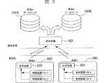
図1は、本発明の一実施形態の車載制御装置の更新情報通信システムの概要を示している。
情報管理基地局装置100(以下、基地局100と略称する)は、データベース102を有するサーバ101と、電磁波による移動体通信(無線通信)を行うための送受信機103と、無線通信用のアンテナ104とを有する。
基地局100のサーバ101は、自動車メーカ、ディーラ等に設置され、管理対象の多数の車両(自動車)200の車載制御装置のプログラムや車両の制御に必要な各種データ、ユーザ情報を一括管理する。この一括管理のために、サーバ101のデータベース102は、管理対象の全車両の車載制御装置(車載ECU)のプログラムや車両の制御に必要な各種データを、各車種毎あるいは車載制御装置の種類毎に格納しており、管理対象の車両情報(ユーザ情報)を各車両毎に格納している。
データベース102が格納する車両情報は、各車両(ユーザ)固有のものであり、図2(a)、(b)に示されているように、各車両毎に、車両識別情報であると共に通信先情報である車両管理番号と、車載LAN上の車載制御装置毎の管理番号、各車載制御装置毎のプログラムバージョン情報と、プログラムの書き換えの中断を示す書換保留フラグの有無を含む。
図2(a)は、ある車両Aの車両情報であり、図2(b)は、他の車両Bの車両情報である。これらの車両情報において、制御装置1は、車載の、たとえば、エンジン制御装置201であり、制御装置2は変速機制御装置202である。
この更新情報通信システムでは、一つの基地局100に対して複数台の車両(自動車)200が属する。
車両200は、各々、車載制御装置として、電子制御式のエンジン制御装置(E−ECU)201、変速機制御装置(AT−ECU)202、空気調和装置用制御装置203等を含み、これらは、CAN(Controller Area Network)等による車載LAN204によって双方向にデータ通信可能に接続されている。車載LAN204には、電磁波による移動体通信(無線通信)を行うための送受信機205と、表示器206が接続されている。
基地局100と当該基地局100の管理下にある車両200とは、車載制御装置の情報更新のために、双方向の移動体通信(無線通信)が行われる。基地局100と車両200との移動体通信は、S−バンド衛星通信・放送システム等の衛星通信、DSRC(Dedicated Short Range Communication)等の専用狭域通信、自動車電話網(公衆回線による携帯電話網)によって双方向に行われる。
各車両200は、基地局100よりの通信により、受動的に、エンジン制御装置201、変速機制御装置202、空気調和装置用制御装置203等のすべての車載制御装置のプログラム、制御定数、それら制御に必要な各種パラメータ等のデータの書換更新、すなわち、アップデートが行われる。
これは、制御プログラム等のアップデートが必要になると、管理対象の車両200にアップデートリクエストとして、Wake−Up要求のメッセージを送出し、基地局主導のもとに、制御プログラム等のアップデートを行うことを意味する。
基地局100は、アップデートのイベントが発生すると、そのアップデートの対象になる車載制御装置の型式の問合せ、つまり、アップデート対象の車載制御装置の有無を、当該基地局100の管理下にある全車両200に対して一斉に行い、各車両よりの返信によってアップデート対象の車両200を選び出し、アップデート対象の車両200に対してアップデートを無線通信によって実行する。
このアップデートは、車両200の走行運転を妨げないよう、駐車中で、運転状態にない車両200、つまり、アップデート対象車両であって車両200の走行運転を妨げないアップデート可能状態にある車両200に対して行われる。このため、基地局100は、アップデートリクエスト先の車両200に対して問い合わせを行い、リクエスト先の車両200より自車両がアップデート可能状態である旨の返信を受信した場合にのみ、アップデートを実行し、アップデート可能状態でない旨の返信を受信した場合には、アップデートが開始されるまで、アップデートリクエスト(Wake−Up要求のメッセージ)を繰り返し送信する。
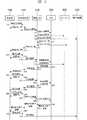
つぎに、基地局100と車両200とのプログラム・データ更新情報通信のシーケンスの概要を、図3を参照して説明する。
通信シーケンスの各ノードとして、基地局100、送受信装置205、車載LAN204、E−ECU(エンジン制御装置)201、AT−ECU(変速機制御装置)202、表示装置206がある。送受信装置205と、車載LAN204と、E−ECU201と、AT−ECU202と表示装置206は車両200側であり、基地局100と送受信装置205とが無線による通信を行う。
図3において、縦方向が時間軸方向であり、通信シーケンスとして、(1)、(2)、(3)…〜(34)が順次実行される。
(1)基地局100がWake−Up(目覚め)要求のメッセージを車載の送受信装置205へ送信する。
(2)車載の送受信装置205がWake−Up要求に対する返信(ACK:accknowledge)を基地局100へ送信する。
(3)車載の送受信装置205より車載LAN204へWake−Up要求を出す。
(4)車載LAN204からE−ECU201へWake−Up要求を出す。
(5)車載LAN204からAT−ECU202へWake−Up要求を出す。
これで、車両100がイグニッションキースイッチ・オフの状態下にあっても、基地局100からのWake−Up要求によって制御装置(E−ECU201やAT−ECU205)がWake−Upする。
(6)車載LAN204が表示装置206へWake−Up中であることの表示要求を出す。
(7)E−ECU201がWake−Upした旨のメッセージを車載LAN204へ送る。
(8)AT−ECU205がWake−Upした旨のメッセージを車載LAN204へ送る。
(9)車載LAN204の下の全ての制御装置がWake−Upした旨のメッセージを送受信装置205へ送る。
(10)送受信装置205は、これを受け、その旨(Wake−Up完了)のメッセージを基地局側100へ送信する。
(11)つぎに、基地局側100が車載の送受信装置205に対してプログラム等のデータを書き換える対象の制御装置の型式の問合せを行う。つまり、基地局側100が車載の送受信装置205に対して書換対象の制御装置の型式データを送信する。
(12)送受信装置205は型式の問合せのメッセージを受信した旨の返信(ACK)を基地局100に行う。
(13)送受信装置205から車載LAN204へ型式確認のメッセージを出す。である。
(14)型式確認のメッセージを受けた車載LAN204はE−ECU201に対して対象か否かの問合せのメッセージを送る。
(15)また、車載LAN204はAT−ECU202に対しても対象か否かの問合せのメッセージを送る。
(16)E−ECU201が書き換えの対象であるとすると、E−ECU201が対象である旨の返信メッセージを車載LAN204へ送る。これは、基地局側100からの情報によって書換が必要であるか否かを車両側で判別することを意味する。
(17)その返信メッセージ(対象返信)を車載LAN204から送受信装置205へ送る。
(18)つぎに、送受信装置205から基地局100へ対象確認の返信を送出する。
(19)つぎに、基地局201から送受信装置205へ現状の車両の状況確認のメッセージ送信する。
(20)送受信装置205は基地局201へ状況確認のメッセージを受信した旨の返信(ACK)を基地局100へ送信する。
(21)送受信装置205から車載LAN204へ状況確認の要請のメッセージを出す。
(22)状況確認の要請メッセージを受けた車載LAN204は、E−ECU201に現状の状況確認の要請メッセージを送る。
(23)現状の車両の状況は、E−ECU201が入力する各種スイッチ、センサの信号によって知ることができるから、E−ECU201は、これらに基づき現状の車両の状況を検知し、車載LAN204へ状況の確認結果を返信する。である。
(24)状況確認結果のメッセージを受けた車載LAN204は、そのメッセージを送受信装置205へ送る。
(25)そして、送受信装置205が状況確認結果のメッセージを基地局100へ送信する。
尚、この通信シーケンス例では、状況の確認結果が、書き換え可能な状況、すなわち、アップデート可能状態にあるものとする。
(26)状況の確認結果(OK結果)を受けた基地局100は、書き換えプログラムを送受信装置205へ送信する。
(27)書き換えプログラムを受信した送受信装置205は、正常受信であった旨のACKを基地局100へ送信する。
(28)送受信装置205が書き換えプログラムを正常受信すると、送受信装置205から書き換えプログラムを車載LAN204へ転送する。
(29)車載LAN204からE−ECU201にプログラム書き込み指示と書き換えプログラムへ転送する。これにより、E−ECU201のプログラムの書き換えが行われる。
(30)E−ECU201のプログラム書き換えが終了すると、E−ECU201から車載LAN204へ書き換え終了のメッセージを送る。
(31)車載LAN204は書き換え終了のメッセージを送受信装置205を送る。
(32)送受信装置205は基地局100へプログラムの書き換え終了のメッセージを送信する。
(33)プログラムの書き換えの終了を確認した基地局100は、送受信装置205へ車載の表示装置206へプログラムの書き換えがあった旨の表示を行う指示(表示要求)のメッセージを送信する。
(34)送受信装置205が表示要求を受信すると、表示装置206がプログラムの書き換えがあった旨の表示を行う。
つぎに、本発明の対象となる車載制御装置のプログラム及びデータの更新情報通信システムにおける基地局100側から車両200側へのデータ送信の一例を、図4を参照して説明する。図4では、車両200として、2車種の車両A、Bのデータ送信形式を示している。
車両A用、車両B用の各々のデータベース102A、102B及び送受信機103は、基地局100側である。データベース102Aは車両Aのデータを管理しており、データベース102Bは車両Bのデータを管理している。
車載制御装置のプログラムの書き換えが必要となった場合には、データベース102A、102Bが格納している書き換え用プログラムを送受信機103によって送信することが行われる。
前記車両A及び車両Bの書き換えプログラムは、データPa11、Pa21、Pb11、Pb21のようにパケットとして分割して送信される。
データPa11は車両Aの制御装置1(E−ECU)のプログラムデータの1パケット、データPb11は車両Bの制御装置1(E−ECU)のプログラムデータの1パケット、データPa21は車両Aの制御装置2(AT−ECU)のプログラムデータの1パケット、データPb21は車両Bの制御装置2(AT−ECU)のプログラムデータの1パケットである。
車両Aに送信されるパケットデータは、車載の送受信機205で受信され、それぞれの対象の制御装置に転送される。車両Bに送信されるパケットデータも、同様に、車載の送受信機205で受信され、それぞれの対象の制御装置に転送される。 つぎに、本発明の対象となる車載制御装置のプログラム及びデータの更新情報通信システムにおける車両200側から基地局100側へのデータ送信の一例を、図5を参照して説明する。
車両Aの制御装置1、制御装置2のプログラムデータの書き換えが終了すると、車載の送受信機205に書き換え終了データを伝える。送受信機205は書き換え終了データを基地局100側の送受信機103に向けて送信する。基地局100で受信された書き換え終了データは車両A用のデータベース102Aに登録されることとなる。車両Bに関しても同様である。
図6は、本発明の対象となる更新情報通信システムの基地局100側が発信する最初のプログラムデータのパケットのフレームフォーマットの一例を示している。プログラムデータのパケットは、ヘッダ601、対象車両管理番号領域602、プログラム管理領域603、データ領域604、チェック符合領域605、及びエンドマーク606で構成されている。
プログラム管理領域603は、更に、対象制御装置管理番号部607、型式部608、ベースプログラム管理ナンバ部609、固有ナンバ(製造ナンバ)部610、プログラムバージョン部611で構成されている。
図7は、本発明の対象となる更新情報通信システムの基地局100側が発信する初回より後のプログラムデータのパケットのフレームフォーマットの一例を示している。プログラムデータのパケットは、ヘッダ701、対象者車両管理番号領域702、データ領域703、チェック符合領域704、及びエンドマーク705で構成されている。
データ領域703は、更に、書き込みナンバ部707、プログラム先頭アドレス部708、プログラム終端アドレス部709、及びプログラムデータ部710で構成されている。
図8は、車両200の車載制御装置であるエンジン制御装置201によるエンジン制御システムの一例を示している。
内燃機関(以下、エンジンと略称する)801は、吸入空気量を、スロットル絞り弁802や、スロットル絞り弁802をバイパスして吸気管804へ接続された流路の流路面積を制御するアイドルスピードコントロールバルブ(ISC)803によって制御される。吸気管804には吸気管圧力を検出する吸気管圧力センサ805が接続されている。
エンジン801には、要求する燃料を供給する燃料噴射弁806、エンジン燃焼室内に供給された燃料と空気の混合気の点火を行う点火栓814が各気筒毎に取り付けられている。また、エンジン801には、エンジン制御装置201が出力する点火信号に基づいて点火栓814に点火エネルギを供給する点火モジュール808が接続されている。
エンジン制御装置201は、吸気管圧力センサ805、クランク角度センサ807、エンジン冷却水温を検出する水温センサ809、酸素濃度センサ810、自動変速装置のドライブレンジを検出するドライブレンジセンサ811、パーキングブレーキのオン/オフを検出するパーキングブレーキスイッチ812、エンジン801の運転、停止のメインスイッチであるイグニッションキースイッチ813の各々より信号を入力し、それらに基づいて燃料制御、点火制御を行う。
この実施形態では、吸気管圧力を検出して燃料制御を成立させているが、エンジンの吸入空気量を検出しても燃料制御は成立する。
エンジン制御装置201は、CAN等による車載LAN204と接続され、他の車載機器との間でデータの送受信が可能な構成となっている。
図9は、車両200の車載制御装置であるエンジン制御装置201の内部構成を示している。エンジン制御装置201は、CAN対応のマイクロコンピュータによるものであり、LSIによるI/Oドライバ901と、演算処理装置(MPU)902と、演算処理装置902の制御手順(制御プログラム)や制御定数を格納するフラッシュメモリ(NV−ROM)903と、演算処理装置902の計算結果等を格納する揮発性メモリ905とを有し、車載LANコントローラ906に接続されている。
I/Oドライバ901の入力側には、スロットル開度センサ911、吸気管圧力センサ805、クランク角センサ807、水温センサ809、酸素濃度センサ810、車速センサ913、ドライブレンジセンサ811、パーキングブレーキスイッチ812、イグニッションキースイッチ813が接続されている。
I/Oドライバ901の出力側には、エンジン制御を実行するアクチュエータ(エンジン制御アクチュエータ)として、燃料噴射弁806と、点火モジュール808に設けられている点火コイル920、アイドルスピードコントロールバルブ(ISC)803が接続されている。燃料噴射弁806と点火コイル920は各気筒ごとに設けられるから、4気筒エンジンであれば、1気筒燃料噴射弁806−1〜4気筒燃料噴射弁806−4の4個の燃料噴射弁が接続され、1気筒点火コイル920−1〜4気筒点火コイル920−4の4個の点火コイルが接続される。
I/Oドライバ901は、エンジンに設置された上述の各センサ、スイッチの電気的信号をディジタル演算処理用の信号に変換し、ディジタル演算用の制御信号を上述のエンジン制御アクチュエータの駆動信号に変換する。
演算処理装置902は、フラッシュメモリ903に格納されている制御プログラムを実行し、I/Oドライバ901からのディジタル演算処理用の信号に基づいてエンジンの状態を判断し、エンジンの要求する燃料量、点火時期等を制御プログラムによって予め定められている手順に基づいて計算し、その計算された値を前述のI/Oドライバ901に出力する。
演算装置902は、内部にフラッシュメモリ903の書き換えを可能とするフラッシュメモリ書き込み部904を含んでいる。
なお、揮発性メモリ905には、前述のイグニッションキースイッチ813がオフで、エンジン制御装置201に電源が供給されない場合でも、メモリ内容を保存することを目的としたバックアップ電源が接続されることもある。また、LANコントローラ906が演算装置906の内部に含まれることもある。
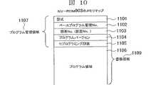
フラッシュメモリ903のメモリマップ構成の一例を、図10を参照して説明する。フラッシュメモリ903は、型式部1101、ベースプログラム管理番号部1102、固有番号(製造番号)部1103、プログラムバージョン部1104、プログラム書き換え回数部1105によるプログラム管理領域1107と、プログラム領域1106のマッピングとなっている。ベースプログラム管理番号1102は制御装置が最初にリリースされた時のデフォルトプログラムの管理番号である。メモリマップはプログラム管理領域1107とプログラム領域1108で構成されており、プログラムバージョン部1104とプログラム書き換え回数部1105とログラム領域1106がプログラム書換領域となっている。
つぎに、更新情報通信システムにおける車両100側のデータ受信と書き込み形態を、図11を参照して説明する。基地局100側から送信されたパケットデータPa11、Pa12、Pa13、Pa14…は、送受信装置205に連続した一つのデータDaとして構築される。データDaは車載LAN204を通して車載制御装置、例えば、E−ECU201のMPU902に送信される。MPU902にはフラッシュメモリ書込み部904があり、データDaはフラッシュメモリ書込み部904に転送され、データDa11、Da12、Da13…に分割し、フラッシュメモリ903の書換領域1109を書き換えていく。
つぎに、更新情報通信システムにおける車両200側の書き換えのOK/NG判定の処理ルーチンを、図12を参照して説明する。
まず、書き換え要求を受信する(ステップ1701)。OK/NG判定の処理ルーチンは、当該書き換え要求を受信することで起動し、送受信機205がWake−Upする(ステップ1702)。続いて、車載LAN204、書き換え対象となる車載制御装置が順にWake−Upする(ステップ1702、1703)。本実施形態では、エンジン制御ECU201が書き換え対象の場合の例である。
つぎに、イグニッションキースイッチ813がオンかオフかを判断する(ステップ1705)。パーキングブレーキスイッチ812がオンかオフかを判断するステップ1706)。ドライブレンジセンサ811により検知されるドライブポジションがPレンジか否かを判断する(ステップ1707)。そして。車速センサ913により検出される車速が0か否かを判断する(ステップ1708)。
イグニッションキースイッチ812がオフ、パーキングブレーキスイッチ812がオン、自動変速機のドライブポジションがPレンジ、且つ車速が0の場合には、車両200が駐車中で、運転状態でなく、アップデート可能状態、すなわち書き換えOKと判定し(ステップ1709)、書き換えOK判定のメッセージを基地局100へ送信する(ステップ1710)。
上記以外の場合には、すなわち、イグニッションキースイッチ812がオフ、パーキングブレーキスイッチ812がオン、自動変速機のドライブポジションがPレンジ、車速が0の一つでも成立しない場合には、書き換えNGと判定し(ステップ1711)、書き換えNG判定のメッセージを基地局100へ送信する(ステップ1712)。
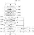
つぎに、更新情報通信システムの基地局100側の書換処理ルーチンを、図13を参照して説明する。
まず、書き換えの指示があるか否かを判断する(ステップ2001)。書き換え指示がない場合にはそのまま終了する。
書き換え指示があることが判断された場合には、現在、プログラム書き換え中であるか否かを判断する(ステップ2002)。書き換え中の場合には、書き換えを続行するように分岐する。書き換え中でない場合には、初回の書き換えかどうかを判断する(ステップ2003)。書き換えが初回でない場合には、前回の書き換え待機から所定の時間以上経過しているかどうか判断する(ステップ2004)。所定時間以上経過している場合には、書き換え要求を発信する(ステップ2005)。これに対し、所定時間以上経過していない場合には、そのまま終了することとなる。 つぎに、車両100側から書き換えOK判定の受信があるかどうかを判断する(ステップ2006)。NGの受信があった場合にはそのまま終了する。これに対し、書き換えOK判定のあった場合には、本ルーチンの書き換えプログラム送信の段階に入る。
その後、車両100側から書き換えNGの受信がないかどうか判断する(ステップ2007)。書き換えNGの受信があった場合には、書き換え待機判定を行う(ステップ2013)。
書き換えNGの受信がない場合には、書き換えが正常に終了したかどうかを判断する(ステップ2008)。書き換えが正常に終了していれば、対象のデータベース102に、対象車両固有番号と対象制御装置番号を登録する(ステップ2014、2015)。
書き換えが終了していない場合には、書き換えプログラムの送信が初回かどうかを判断する(ステップ2009)。書き換えプログラム送信が初回(書き換えプログラムのパケットが初回)の場合には、対象車両固有番号、対象制御装置番号を発信し(ステップ2010、2011)、書き換え対象の車両及び車載制御装置を特定する。書き換えプログラムが初回でない場合(書き換えプログラムの初回より後のパケットの場合)には、継続して書き換えプログラムを送信する(ステップ2012)。
図14は、更新情報通信システムの基地局100の状態遷移の一例を示している。ブロック1801は待機状態である。書き換え指示があった場合には、ブロック1802の書き換え判断の状態に遷移する。
ブロック1802において、車両側から書き換えNGを受信した場合、もしくは、前回の書き換え待機から所定時間内の場合には、ブロック1801の待機状態に戻る。これに対し、車両側から書き換えOKを受信した場合には、ブロック1803に遷移し、書き換えプログラムを送信する。
書き換えプログラムを送信して、書き換えが正常に終了した旨を受信すると、ブロック1804で書き換え終了処理を行う。ここでは、前述した基地局100側のデータベース102の更新を行う。ブロック1803で書き換えNGの信号を受信した場合には、ブロック1805で書き換え待機処理を行う。ここでは前述したデータベース102に対して書き換え待機状態である旨を記録する。その後に、ブロック1801で待機処理に遷移する。
図15は、更新情報通信システムの車両100の状態遷移の一例を示している。す。本実施形態では、通常、車両100は、イグニッションキーがオフ状態の停止状態であり、ブロック1901に示すように車両側のシステムはスリープ状態となっている。
基地局100側から書き換え要求を受信すると、ブロック1902へ遷移して書き換えOKか否かを判断する。ここで、書き換えNGと判定した場合には、再度ブロック1902へ遷移する。書き換えOKと判定した場合には、ブロック1903へ遷移し、書き換えプログラムを受信する。
書き換えプログラムの受信が完了すると、ブロック1904へ遷移し、書き換えが実行される。書き換えが正常に終了した場合には、ブロック1905からブロック1906へ遷移し、書き換え終了処理、及び書き換え正常である旨の発信を行い、初期状態のブロック1901へ戻る。
ブロック1904でプログラムの書き換え中に、イグニッションキースイッチがオンした、車速が0でなくなった、ドライブポジションがパーキング以外となった、パーキングブレーキがオフとなった、もしくは書き換えが途中で失敗した等が発生した場合には、ブロック1907へ遷移し、書き換え中断処理を行う。書き換え中断処理は、どこまで書き換えが行なわれたかを、車載制御装置に記憶させる等を行う。
その後、ブロック1908で書き換えが中断された旨を送信し、初期状態のブロック1901へ遷移する。
本発明により、アップデートを行うべき車両をディーラに移動することなく対象とする車両の車載制御装置のプログラムまたはデータのアップデートが可能となる。また対象車両の車載制御装置のプログラム及びデータのアップデート状況をデータベースにより管理することにより、管理工数を大幅に低減できる。
このアップデートは、車両メーカ、ディーラが管理する基地局100の指示によってアップデート対象の全車両に対して自動的に行われるから、車両ユーザに何ら負担をかけることなく、車載制御装置のアップデートが常に確実に行われ、車載制御装置が常に最適な状態、あるいは、より良い状態に保たれ、車両運転の運転性、燃料経済性、排気ガス性能が最適な状態になる。
また、車両ユーザが、忘却により、あるいは故意にアップデートを行わないこと等、ユーザサイドの過失等によって車載制御装置が最適な状態に保たれないことを未然に防ぐこともできる。
図16は、本発明の対象となる更新情報通信システムの車両100側の車載制御装置のフラッシュメモリ構成の他の例を示す。車載LAN204は車載制御装置内部のMPU902に接続されている。MPU902以降は、バンク切替部1404、フラッシュメモリバンク(バンク1、2)1405、1406で構成される。
図示の状態は、フラッシュメモリバンク1405のプログラムデータが書き換えられている状態である。書き換えが正常に終了するまで、車載制御装置、たとえば、E−ECU201は、フラッシュメモリバンク1406のプログラム及びデータで制御を行う。
フラッシュメモリバンク1405のプログラム書き換えが正常に終了すると、E−ECU201は、フラッシュメモリバンク1405のプログラム及びデータで制御を開始する。
このバンク切替式のフラッシュメモリの使用によれば、随時、プログラム及びデータのアップデートを行うことができる。
図17は、本発明の対象となる更新情報通信システムの車両100側の車載制御装置のフラッシュメモリ構成の他の例を示す。フラッシュメモリ903の内部は、プログラムベクター1505と、バンク(1)1506、バンク(2)1507のマッピングで構成されている。
図示の状態は、バンク1506のプログラムデータが書き換えられている状態である。書き換えが正常に終了するまで、車載制御装置、たとえば、E−ECU201は、ンク1507のプログラム及びデータで制御を行う。
バンク1506のプログラム書き換えが正常に終了すると、プログラムベクター1505の内容が書き換えられ、E−ECU201は、バンク1 1506のプログラム及びデータで制御を開始する。この場合も、随時、プログラム及びデータのアップデートを行うことができる。
図18は、更新情報通信システムの基地局100側と車両200側の構成例を示している。
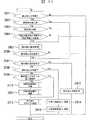
基地局100は、プログラム等のバージョン管理局1002及び送受信機1003を含んでいる。
車両200は、送受信機1005、車載LAN1006、エンジン制御ECU1007、トランスミッションECU1008、エアコン制御ECU1009を有し、各々がLANにより連結されている。尚、本実施形態では、LAN上に3つの車載制御装置が連結されているが、それより複数の制御装置を連結させることも可能である。
図19、図20は、各々、更新情報通信システムの基地局100側と車両200側の他の構成例を示している。
図12に示されている構成例では、車両100に搭載されている送受信機1005とエンジン制御ECU1206、トランスミッション1207、エアコン制御ECU1208とが車載LANを介さずに直接接続されている。
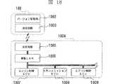
図13に示されている構成例では、エンジン制御ECU1007、トランスミッションECU1008、エアコン制御ECU1009の各々に、送受信機1306、1307、1308が個別に接続されている。尚、個々の送受信機が車載の一つの送受信機にデータ転送し、まとめて基地局100側に送る構成でも有効である(Blue Tooth、もしくは無線LAN)。
上述した実施形態では、基地局100に送受信機103とデータベース102が備えられた構成となっているが、図21に示されているように、基地局100はデータベース102のみを備え、送受信機2101とは無線または有線(インターネット、電話回線、専用回線等)2102によりデータ送受信を行う構成でも問題はない。Preferred embodiments according to the present invention will be described with reference to the accompanying drawings.
FIG. 1 shows an overview of an update information communication system of an in-vehicle control device according to an embodiment of the present invention.
An information management base station apparatus 100 (hereinafter abbreviated as a base station 100) includes a
The
The vehicle information stored in the
2A shows vehicle information of a certain vehicle A, and FIG. 2B shows vehicle information of another vehicle B. In these vehicle information, the
In this update information communication system, a plurality of vehicles (automobiles) 200 belong to one
Each of the
Bidirectional mobile communication (wireless communication) is performed between the
Each
This means that when a control program or the like needs to be updated, a Wake-Up request message is sent to the
When an update event occurs, the
This update is performed for a
Next, an outline of a program / data update information communication sequence between the
As nodes of the communication sequence, there are a
In FIG. 3, the vertical direction is the time axis direction, and (1), (2), (3)... To (34) are sequentially executed as the communication sequence.
(1) The
(2) The in-vehicle transmission /
(3) A Wake-Up request is issued from the in-vehicle transmission /
(4) A Wake-Up request is issued from the in-
(5) A Wake-Up request is issued from the in-
Thus, even when the
(6) The in-
(7) The
(8) The AT-
(9) All the control devices under the in-
(10) Upon receipt of this, the transmission /
(11) Next, the
(12) The transmission /
(13) A message for type confirmation is sent from the transmission /
(14) The in-
(15) Further, the in-
(16) If the
(17) The reply message (target reply) is sent from the in-
(18) Next, a reply for object confirmation is sent from the transmission /
(19) Next, a message for confirming the current vehicle status is transmitted from the
(20) The transmission /
(21) A message for requesting status confirmation is sent from the transmission /
(22) The in-
(23) Since the current vehicle status can be known from various switches and sensor signals input by the
(24) The in-
(25) Then, the transmission /
In this communication sequence example, it is assumed that the confirmation result of the situation is a rewritable situation, that is, an updateable state.
(26) Receiving the status confirmation result (OK result), the
(27) The transmission /
(28) When the transmission /
(29) The in-
(30) When the program rewriting of the
(31) The in-
(32) The transmission /
(33) The
(34) When the transmission /
Next, an example of data transmission from the
The
When it is necessary to rewrite the program of the in-vehicle control device, the
The rewriting programs for the vehicle A and the vehicle B are divided and transmitted as packets like data Pa11, Pa21, Pb11, Pb21.
Data Pa11 is one packet of program data of control device 1 (E-ECU) of vehicle A, data Pb11 is one packet of program data of control device 1 (E-ECU) of vehicle B, and data Pa21 is a control device of vehicle A. 1 (AT-ECU) program data packet, and data Pb21 are one program data packet of the vehicle B control device 2 (AT-ECU).
The packet data transmitted to the vehicle A is received by the vehicle-mounted
When rewriting of the program data of the
FIG. 6 shows an example of the frame format of the first program data packet transmitted from the
The
FIG. 7 shows an example of a frame format of a program data packet transmitted from the
The data area 703 further includes a
FIG. 8 shows an example of an engine control system by an
An internal combustion engine (hereinafter abbreviated as “engine”) 801 is an idle speed that controls the flow area of a flow path that is connected to an
The
The
In this embodiment, the fuel control is established by detecting the intake pipe pressure, but the fuel control is established even if the intake air amount of the engine is detected.
The
FIG. 9 shows an internal configuration of an
On the input side of the I /
On the output side of the I /
The I /
The
The
The
An example of a memory map configuration of the
Next, the data reception and writing mode on the
Next, a rewriting OK / NG determination processing routine on the
First, a rewrite request is received (step 1701). The OK / NG determination processing routine is activated by receiving the rewrite request, and the
Next, it is determined whether the ignition
When the ignition
In other cases, that is, when the ignition
Next, a rewrite processing routine on the
First, it is determined whether or not there is an instruction for rewriting (step 2001). If there is no rewrite instruction, the process ends.
If it is determined that there is a rewrite instruction, it is determined whether or not the program is currently being rewritten (step 2002). If rewriting is in progress, the program branches to continue rewriting. If it is not being rewritten, it is determined whether or not it is the first rewrite (step 2003). If rewriting is not the first time, it is determined whether or not a predetermined time has elapsed since the previous rewriting standby (step 2004). If the predetermined time has elapsed, a rewrite request is transmitted (step 2005). On the other hand, if the predetermined time or more has not elapsed, the processing ends as it is. Next, it is determined whether or not a rewrite OK determination is received from the
Thereafter, it is determined whether or not rewriting NG is received from the
If no rewriting NG has been received, it is determined whether rewriting has been completed normally (step 2008). If the rewriting has been completed normally, the target vehicle unique number and the target control device number are registered in the target database 102 (
If the rewriting has not been completed, it is determined whether or not the rewriting program is transmitted for the first time (step 2009). When the rewrite program transmission is the first time (the rewrite program packet is the first time), the target vehicle unique number and the target control device number are transmitted (
FIG. 14 shows an example of state transition of the
In
When the rewriting program is transmitted and the fact that the rewriting has been normally completed is received, a rewriting end process is performed at
FIG. 15 shows an example of state transition of the
When a rewrite request is received from the
When reception of the rewriting program is completed, the process proceeds to block 1904, where rewriting is executed. When the rewriting has been completed normally, the process proceeds from
While the program is being rewritten in
After that, the fact that rewriting is interrupted is transmitted in
According to the present invention, it is possible to update a program or data of an in-vehicle control device of a target vehicle without moving the vehicle to be updated to a dealer. Moreover, the management man-hours can be significantly reduced by managing the update status of the program and data of the on-vehicle control device of the target vehicle using a database.
Since this update is automatically performed on all the vehicles to be updated according to instructions from the
In addition, it is possible to prevent a vehicle user from being kept in an optimal state due to user's negligence or the like due to forgetting or intentionally not updating.
FIG. 16 shows another example of the flash memory configuration of the in-vehicle control device on the
The state shown in the figure is a state in which the program data in the
When the program rewriting of the
According to the use of the bank switching type flash memory, the program and data can be updated at any time.
FIG. 17 shows another example of the flash memory configuration of the in-vehicle control device on the
The state shown in the figure is a state in which the program data in the
When the program rewriting of the
FIG. 18 shows a configuration example of the update information communication system on the
The
The
FIGS. 19 and 20 show other configuration examples of the
In the configuration example shown in FIG. 12, the
In the configuration example shown in FIG. 13,
In the embodiment described above, the
Claims (11)
Translated fromJapaneseApplications Claiming Priority (1)
| Application Number | Priority Date | Filing Date | Title |
|---|---|---|---|
| PCT/JP2003/016039WO2005059862A1 (en) | 2003-12-15 | 2003-12-15 | Information updating method of vehicle-mounted control apparatus, update information communication system, vehicle-mounted control apparatus, and information management base station apparatus |
Publications (2)
| Publication Number | Publication Date |
|---|---|
| JPWO2005059862A1true JPWO2005059862A1 (en) | 2007-07-12 |
| JP4361902B2 JP4361902B2 (en) | 2009-11-11 |
Family
ID=34685691
Family Applications (1)
| Application Number | Title | Priority Date | Filing Date |
|---|---|---|---|
| JP2005512188AExpired - Fee RelatedJP4361902B2 (en) | 2003-12-15 | 2003-12-15 | In-vehicle control device information update method, update information communication system, vehicle-mounted control device, and information management base station device |
Country Status (4)
| Country | Link |
|---|---|
| US (1) | US8290659B2 (en) |
| EP (1) | EP1699031A4 (en) |
| JP (1) | JP4361902B2 (en) |
| WO (1) | WO2005059862A1 (en) |
Families Citing this family (84)
| Publication number | Priority date | Publication date | Assignee | Title |
|---|---|---|---|---|
| US7277028B1 (en)* | 2003-10-20 | 2007-10-02 | Garth Janke | Method and system for inter-vehicular communications and information reporting |
| JP4361902B2 (en)* | 2003-12-15 | 2009-11-11 | 株式会社日立製作所 | In-vehicle control device information update method, update information communication system, vehicle-mounted control device, and information management base station device |
| US7366589B2 (en)* | 2004-05-13 | 2008-04-29 | General Motors Corporation | Method and system for remote reflash |
| JP4813084B2 (en)* | 2005-04-27 | 2011-11-09 | 京セラ株式会社 | Communication system, radio communication terminal and method thereof |
| JP4639934B2 (en)* | 2005-05-06 | 2011-02-23 | 株式会社デンソー | Vehicle control system |
| JP2007065856A (en)* | 2005-08-30 | 2007-03-15 | Fujitsu Ten Ltd | Information rewriting system and information rewriting device |
| US20070050095A1 (en)* | 2005-09-01 | 2007-03-01 | Polaris Industries Inc. | Controller area network based self-configuring vehicle management system and method |
| US20070185624A1 (en)* | 2006-02-07 | 2007-08-09 | General Motors Corporation | Method for remote reprogramming of vehicle flash memory |
| US7873610B2 (en) | 2006-05-26 | 2011-01-18 | Andrew S Poulsen | Meta-configuration of profiles |
| JP2008019843A (en)* | 2006-07-14 | 2008-01-31 | Yamaha Motor Co Ltd | Engine setting system and server device used for it |
| JP4791301B2 (en)* | 2006-09-13 | 2011-10-12 | 株式会社オートネットワーク技術研究所 | In-vehicle LAN system |
| JP2008087666A (en)* | 2006-10-03 | 2008-04-17 | Denso Corp | Data setting change device, car navigation device, and data setting change system |
| JP4899848B2 (en)* | 2006-12-13 | 2012-03-21 | 株式会社デンソー | In-vehicle system |
| EP2097281A4 (en)* | 2006-12-26 | 2010-12-29 | Carrier Corp | System and method to program air conditioner modules |
| DE102007006614A1 (en)* | 2007-02-06 | 2008-08-07 | Daimler Ag | Application of a Distributed Diagnostic Architecture in AUTOSAR |
| US7778213B2 (en)* | 2007-02-23 | 2010-08-17 | Gm Global Technology Operations, Inc. | Method and system for selectively communicating with mobile platforms |
| US8391775B2 (en)* | 2007-03-09 | 2013-03-05 | Airbiquity Inc. | Mobile digital radio playlist system |
| FR2914080A1 (en)* | 2007-03-23 | 2008-09-26 | Renault Sas | SYSTEM AND METHOD FOR MANAGING DATA FROM AND TO A MOTOR VEHICLE. |
| US7725129B2 (en)* | 2007-05-16 | 2010-05-25 | Oliver David Grunhold | Cell phone based vehicle control system |
| US8588852B2 (en)* | 2007-09-28 | 2013-11-19 | Alcatel Lucent | Method and apparatus for controlling a phased deployment of a base station using an operational state of a vehicle |
| ITVE20070085A1 (en)* | 2007-11-08 | 2009-05-09 | B M Due S R L | METHOD AND EQUIPMENT FOR THE DIFFUSION OF INFORMATION ON BOARD VEHICLES IN TRANSIT |
| KR100866617B1 (en) | 2007-11-09 | 2008-11-04 | 호진형 | Vehicle driving information management system and method |
| US8332838B2 (en)* | 2007-11-14 | 2012-12-11 | Continental Automotive Systems, Inc. | Systems and methods for updating device software |
| JP4906801B2 (en)* | 2008-07-11 | 2012-03-28 | 日立オートモティブシステムズ株式会社 | In-vehicle electronic control unit data writing system and in-vehicle electronic control unit |
| WO2010053803A1 (en)* | 2008-10-28 | 2010-05-14 | Airbiquity Inc. | Purchase of a piece of music being played on a radio in a vehicle |
| KR101539119B1 (en)* | 2008-12-24 | 2015-07-24 | 두산인프라코어 주식회사 | Construction machine remote management system and method for controlling data receiving/transmitting on key off state |
| WO2010085557A1 (en)* | 2009-01-26 | 2010-07-29 | Psi Patents, Llc | T-harness connection for vehicle remote starters |
| FR2943152B1 (en)* | 2009-03-13 | 2019-03-15 | Airbus Operations | AUTOMATED SOFTWARE DOWNLOADING METHODS AND DEVICES IN AN APPARATUS SUCH AS AN AIRCRAFT INCLUDING UPDATING THE ASSOCIATED DOCUMENTATION |
| DE102009003688A1 (en)* | 2009-03-27 | 2010-10-07 | Loewe Opta Gmbh | Software update for device with several smart devices |
| US8831823B2 (en) | 2009-10-15 | 2014-09-09 | Airbiquity Inc. | Centralized management of motor vehicle software applications and services |
| US8942888B2 (en) | 2009-10-15 | 2015-01-27 | Airbiquity Inc. | Extensible scheme for operating vehicle head unit as extended interface for mobile device |
| US8838332B2 (en)* | 2009-10-15 | 2014-09-16 | Airbiquity Inc. | Centralized management of motor vehicle software applications and services |
| US9002574B2 (en) | 2009-10-15 | 2015-04-07 | Airbiquity Inc. | Mobile integration platform (MIP) integrated handset application proxy (HAP) |
| KR20110071788A (en)* | 2009-12-21 | 2011-06-29 | 한국전자통신연구원 | How to send vehicle information |
| US8688313B2 (en)* | 2010-12-23 | 2014-04-01 | Aes Technologies, Llc. | Remote vehicle programming system and method |
| JP5853205B2 (en)* | 2011-03-29 | 2016-02-09 | パナソニックIpマネジメント株式会社 | Vehicle control device |
| WO2013165995A1 (en) | 2012-04-30 | 2013-11-07 | Thermo King Corporation | Transport refrigeration system controller to engine control unit interface |
| JP6154894B2 (en) | 2012-06-08 | 2017-06-28 | エアビクティ インコーポレイテッド | A method for evaluating electronic sensor data to remotely identify vehicles and monitor driver behavior |
| CN104919833B (en) | 2012-12-20 | 2019-11-08 | 爱尔比奎特公司 | Efficient head unit communication integration |
| US9751422B2 (en)* | 2014-01-15 | 2017-09-05 | Bayerische Motoren Werke Aktiengesellschaft | Device for switching a mode of a vehicle |
| EP3133498B1 (en)* | 2014-04-16 | 2020-08-12 | Clarion Co., Ltd. | Data delivery system, control server, and data delivery method |
| JP5749832B2 (en)* | 2014-05-08 | 2015-07-15 | 日立オートモティブシステムズ株式会社 | Electronic control device for automobile and data writing method in electronic control device for automobile |
| DE102014008479A1 (en)* | 2014-06-07 | 2015-12-17 | Audi Ag | Motor vehicle control unit with power-saving mode for a parking phase |
| US10310838B2 (en) | 2014-06-18 | 2019-06-04 | Hitachi Automotive Systems, Ltd. | Vehicle-mounted program writing device |
| CN110321149B (en) | 2014-06-19 | 2023-08-25 | 日立安斯泰莫株式会社 | Vehicle program writing device |
| US10349631B2 (en) | 2014-07-21 | 2019-07-16 | Nicholas Jay Bonge, JR. | Wireless animal training, monitoring and remote control system |
| US20170298881A1 (en)* | 2014-10-08 | 2017-10-19 | Cummins Filtration Ip, Inc | Integrated smart fuel filtration system |
| EP3209404B1 (en)* | 2014-10-08 | 2021-02-17 | Cummins Filtration IP, Inc. | Integrated smart fuel filtration system |
| US9892296B2 (en) | 2014-11-12 | 2018-02-13 | Joseph E. Kovarik | Method and system for autonomous vehicles |
| US9841970B2 (en)* | 2015-01-13 | 2017-12-12 | Ford Global Technologies, Llc | Vehicle control update methods and systems |
| MX357454B (en)* | 2015-07-16 | 2018-06-26 | Inst Tecnologico Y De Estudios Superiores De Occidente A C | System and method for reprogramming ecu devices (electronic control units) in vehicles, via digital radio. |
| JP6281535B2 (en)* | 2015-07-23 | 2018-02-21 | 株式会社デンソー | Relay device, ECU, and in-vehicle system |
| US9720680B2 (en) | 2015-07-23 | 2017-08-01 | Honda Motor Co., Ltd. | Methods and apparatus for wirelessly updating vehicle systems |
| JP6135723B2 (en)* | 2015-08-20 | 2017-05-31 | コベルコ建機株式会社 | Construction machine and program rewriting system provided with the same |
| ITUB20153843A1 (en)* | 2015-09-24 | 2017-03-24 | Magneti Marelli Spa | ELECTRONIC CONTROL UNIT FOR A ROAD VEHICLE AND ITS MANAGEMENT METHOD |
| DE112016004436T5 (en) | 2015-09-29 | 2018-06-21 | Hitachi Automotive Systems, Ltd. | Board control device and information updating system for an on-board control device |
| CN105894804A (en)* | 2015-12-29 | 2016-08-24 | 乐卡汽车智能科技(北京)有限公司 | Vehicle-mounted taxi booking device |
| US11321072B2 (en) | 2016-03-30 | 2022-05-03 | Ford Global Technologies, Llc | Vehicle computer update authentication |
| CN109074247B (en)* | 2016-03-30 | 2022-10-25 | 福特全球技术公司 | Vehicle Computer Update Certification |
| DE102016207836A1 (en) | 2016-05-06 | 2017-11-09 | Robert Bosch Gmbh | Method and system for updating the software of a motor vehicle sensor |
| US11400997B2 (en) | 2016-05-23 | 2022-08-02 | Indian Motorcycle International, LLC | Display systems and methods for a recreational vehicle |
| JP6260068B1 (en)* | 2016-09-30 | 2018-01-17 | Kddi株式会社 | Maintenance device, maintenance method, and computer program |
| US10901724B2 (en)* | 2016-10-28 | 2021-01-26 | Kabushiki Kaisha Toshiba | Software update system for mobile body using vehicle-mounted gateway apparatus |
| CN116600372A (en)* | 2016-11-03 | 2023-08-15 | 交互数字专利控股公司 | Method for efficient power saving for waking up a radio |
| US10825266B2 (en) | 2017-01-10 | 2020-11-03 | Cummins Inc. | Wireless ECU configuration updating |
| US10970063B2 (en)* | 2017-04-12 | 2021-04-06 | Sumitomo Electric Industries, Ltd. | Relay apparatus, transfer method, and computer program |
| SE546115C2 (en)* | 2017-06-21 | 2024-05-28 | Walbro Llc | Magento ignition system and ignition control system |
| WO2019009020A1 (en) | 2017-07-04 | 2019-01-10 | 日本電気通信システム株式会社 | Software update device |
| EP3546355B1 (en)* | 2018-03-29 | 2021-07-07 | Airbus Operations GmbH | Aircraft area having a textile display, and an aircraft including such an aircraft area |
| US11560240B2 (en) | 2018-03-29 | 2023-01-24 | Airbus Operations Gmbh | Aircraft area having a textile display, aircraft passenger seat having a textile display, and aircraft including an aircraft area |
| DE112018007680T5 (en)* | 2018-06-29 | 2021-04-22 | Mitsubishi Electric Corporation | Update control apparatus, update control system, and update control method |
| JP2020017059A (en)* | 2018-07-25 | 2020-01-30 | 日本電気株式会社 | Information processing device, information processing system, information processing method and program |
| US11461082B2 (en)* | 2018-08-02 | 2022-10-04 | Citrix Systems, Inc. | Systems and methods for managing releases of global services in a controlled manner |
| JP7111074B2 (en)* | 2018-08-10 | 2022-08-02 | 株式会社デンソー | Vehicle master device, security access key management method, security access key management program, and vehicle electronic control system |
| JP7484096B2 (en)* | 2018-08-10 | 2024-05-16 | 株式会社デンソー | Electronic control device, rewrite execution control method, and rewrite execution control program |
| WO2020032200A1 (en) | 2018-08-10 | 2020-02-13 | 株式会社デンソー | Central device, specification data generation method, and program for generating specification data |
| KR102587084B1 (en) | 2018-09-05 | 2023-10-11 | 현대자동차주식회사 | Apparatus and method for providing update of vehicle |
| KR102598962B1 (en)* | 2018-12-12 | 2023-11-06 | 현대자동차주식회사 | Apparatus and method for coltrolling update of vehicle controller, and vehicle system |
| JP7232062B2 (en) | 2019-01-28 | 2023-03-02 | 日立Astemo株式会社 | Electronic controller and program update method |
| JP7216559B2 (en)* | 2019-02-05 | 2023-02-01 | 日立Astemo株式会社 | How to use electronic controllers and non-volatile memory |
| EP3869471A1 (en)* | 2020-02-24 | 2021-08-25 | Continental Automotive GmbH | Communication method comprising a server and a plurality of on-board units and on-board unit |
| JP7104086B2 (en)* | 2020-02-28 | 2022-07-20 | 矢崎総業株式会社 | Vehicle interior lighting system |
| US11379217B1 (en)* | 2021-05-06 | 2022-07-05 | Sap Se | Feature lifecycle management cockpit for hybrid cloud and edge systems |
| US12409941B1 (en)* | 2024-06-17 | 2025-09-09 | Shenzhen Hobbywing Technology Co., Ltd. | Parameter setting method, device and multi-rotor drone |
Citations (6)
| Publication number | Priority date | Publication date | Assignee | Title |
|---|---|---|---|---|
| JPH02215951A (en)* | 1989-02-15 | 1990-08-28 | Hitachi Ltd | Load sharing control method in automobile |
| JPH09331579A (en)* | 1996-06-11 | 1997-12-22 | Nec Commun Syst Ltd | How to download programs to mobile terminals |
| JP2000134669A (en)* | 1998-10-21 | 2000-05-12 | Alcatel | How to remotely update mobile phone software |
| JP2001342865A (en)* | 2000-05-30 | 2001-12-14 | Toyota Motor Corp | Engine control device |
| JP2002144983A (en)* | 2000-11-14 | 2002-05-22 | Toyoda Mach Works Ltd | Method and device for changing control software of vehicle control device |
| JP2002202895A (en)* | 2000-12-28 | 2002-07-19 | Toyota Central Res & Dev Lab Inc | Vehicle basic function control program update device |
Family Cites Families (36)
| Publication number | Priority date | Publication date | Assignee | Title |
|---|---|---|---|---|
| US4534061A (en)* | 1983-09-06 | 1985-08-06 | General Electric Company | Deterministic multi-access method for a decentralized mobile radio system |
| JPS6238624A (en)* | 1985-08-13 | 1987-02-19 | Nec Corp | Radio communication equipment |
| US4791571A (en)* | 1985-10-29 | 1988-12-13 | Tokyu Corporation | Route bus service controlling system |
| JPH02212951A (en)* | 1989-02-13 | 1990-08-24 | Hitachi Ltd | Memory device and data processing system using it |
| JPH03243025A (en)* | 1990-02-21 | 1991-10-30 | Nec Corp | Radio selective calling receiver capable of updating program |
| US5155689A (en)* | 1991-01-17 | 1992-10-13 | By-Word Technologies, Inc. | Vehicle locating and communicating method and apparatus |
| JPH0512000A (en)* | 1991-07-03 | 1993-01-22 | Fujitsu Ten Ltd | Terminal software version changing method |
| US6694359B1 (en)* | 1991-08-21 | 2004-02-17 | Unova, Inc. | Data collection and dissemination system |
| JPH0633828A (en) | 1992-07-17 | 1994-02-08 | Nippondenso Co Ltd | On-vehicle electronic control |
| JP2959918B2 (en)* | 1992-12-28 | 1999-10-06 | 富士通テン株式会社 | Wireless communication system between base station and mobile station |
| US6748318B1 (en)* | 1993-05-18 | 2004-06-08 | Arrivalstar, Inc. | Advanced notification systems and methods utilizing a computer network |
| US6618668B1 (en)* | 2000-04-26 | 2003-09-09 | Arrivalstar, Inc. | System and method for obtaining vehicle schedule information in an advance notification system |
| US6009355A (en)* | 1997-01-28 | 1999-12-28 | American Calcar Inc. | Multimedia information and control system for automobiles |
| US6680694B1 (en)* | 1997-08-19 | 2004-01-20 | Siemens Vdo Automotive Corporation | Vehicle information system |
| US6430488B1 (en)* | 1998-04-10 | 2002-08-06 | International Business Machines Corporation | Vehicle customization, restriction, and data logging |
| JP3546696B2 (en)* | 1998-04-28 | 2004-07-28 | スズキ株式会社 | Outboard engine management system |
| DE19823123C2 (en)* | 1998-05-23 | 2000-05-25 | Opel Adam Ag | Method for operating a navigation system for motor vehicles |
| US6222463B1 (en)* | 1998-06-25 | 2001-04-24 | Lucent Technologies, Inc. | Vehicle communication network |
| DE19850903A1 (en) | 1998-11-05 | 2000-05-11 | Mannesmann Vdo Ag | Method for reprogramming devices having control units, in particular in motor vehicles |
| US6522875B1 (en)* | 1998-11-17 | 2003-02-18 | Eric Morgan Dowling | Geographical web browser, methods, apparatus and systems |
| WO2000052422A1 (en)* | 1999-03-01 | 2000-09-08 | Global Research Systems, Inc. | Base station system and method for monitoring travel of mobile vehicles and communicating notification messages |
| EP1214852A1 (en)* | 1999-09-02 | 2002-06-19 | Nokia Corporation | A wireless communication terminal for accessing location information from a server |
| KR100331633B1 (en)* | 1999-12-14 | 2002-04-09 | 이계안 | Method and apparatus for controlling a speed of car using a radio frequency device |
| US6629029B1 (en)* | 2000-03-28 | 2003-09-30 | Jacqueline A Giles | Multi-purpose plug-in monitor for vehicles |
| US6604033B1 (en)* | 2000-07-25 | 2003-08-05 | Networkcar.Com | Wireless diagnostic system for characterizing a vehicle's exhaust emissions |
| JP2002044742A (en) | 2000-07-28 | 2002-02-08 | Omron Corp | Operating system for vehicle control apparatus and the apparatus |
| WO2002010908A2 (en) | 2000-08-02 | 2002-02-07 | Siemens Automotive Corporation | Wireless reprogramming of vehicle electronic control units |
| US6826726B2 (en)* | 2000-08-18 | 2004-11-30 | Vaultus Mobile Technologies, Inc. | Remote document updating system using XML and DOM |
| US6438468B1 (en)* | 2000-11-28 | 2002-08-20 | Honeywell International Inc. | Systems and methods for delivering data updates to an aircraft |
| JP3923266B2 (en)* | 2001-03-01 | 2007-05-30 | 株式会社日立製作所 | Mobile terminal for informing position of moving body such as vehicle, moving body position notifying program, computer-readable recording medium recording the program, system for managing position of moving body, and moving body management method |
| DE10131395B4 (en) | 2001-06-28 | 2006-08-17 | Daimlerchrysler Ag | Method for transmitting software modules |
| JP2003114133A (en)* | 2001-10-05 | 2003-04-18 | Pioneer Electronic Corp | Communication navigation method, communication navigation system, terminal device |
| US7283047B2 (en)* | 2003-08-01 | 2007-10-16 | Spectrum Tracking Systems, Inc. | Method and system for providing tracking services to locate an asset |
| US7277028B1 (en)* | 2003-10-20 | 2007-10-02 | Garth Janke | Method and system for inter-vehicular communications and information reporting |
| JP4361902B2 (en)* | 2003-12-15 | 2009-11-11 | 株式会社日立製作所 | In-vehicle control device information update method, update information communication system, vehicle-mounted control device, and information management base station device |
| US7899610B2 (en)* | 2006-10-02 | 2011-03-01 | Inthinc Technology Solutions, Inc. | System and method for reconfiguring an electronic control unit of a motor vehicle to optimize fuel economy |
- 2003
- 2003-12-15JPJP2005512188Apatent/JP4361902B2/ennot_activeExpired - Fee Related
- 2003-12-15WOPCT/JP2003/016039patent/WO2005059862A1/enactiveApplication Filing
- 2003-12-15EPEP03778925Apatent/EP1699031A4/ennot_activeWithdrawn
- 2003-12-15USUS10/582,853patent/US8290659B2/ennot_activeExpired - Fee Related
Patent Citations (6)
| Publication number | Priority date | Publication date | Assignee | Title |
|---|---|---|---|---|
| JPH02215951A (en)* | 1989-02-15 | 1990-08-28 | Hitachi Ltd | Load sharing control method in automobile |
| JPH09331579A (en)* | 1996-06-11 | 1997-12-22 | Nec Commun Syst Ltd | How to download programs to mobile terminals |
| JP2000134669A (en)* | 1998-10-21 | 2000-05-12 | Alcatel | How to remotely update mobile phone software |
| JP2001342865A (en)* | 2000-05-30 | 2001-12-14 | Toyota Motor Corp | Engine control device |
| JP2002144983A (en)* | 2000-11-14 | 2002-05-22 | Toyoda Mach Works Ltd | Method and device for changing control software of vehicle control device |
| JP2002202895A (en)* | 2000-12-28 | 2002-07-19 | Toyota Central Res & Dev Lab Inc | Vehicle basic function control program update device |
Also Published As
| Publication number | Publication date |
|---|---|
| EP1699031A1 (en) | 2006-09-06 |
| US8290659B2 (en) | 2012-10-16 |
| EP1699031A4 (en) | 2008-01-23 |
| US20070100513A1 (en) | 2007-05-03 |
| WO2005059862A1 (en) | 2005-06-30 |
| JP4361902B2 (en) | 2009-11-11 |
Similar Documents
| Publication | Publication Date | Title |
|---|---|---|
| JP4361902B2 (en) | In-vehicle control device information update method, update information communication system, vehicle-mounted control device, and information management base station device | |
| JP3151831B2 (en) | Vehicle information communication device and vehicle information communication system | |
| US12041171B2 (en) | Over-the-air vehicle systems updating and associated security protocols | |
| US8306521B2 (en) | Vehicle control apparatus with data reprogrammable via wireless communication network | |
| CN106774272B (en) | A kind of vehicular engine based on cloud computing platform remotely monitors, demarcates and big data collection system and its working method | |
| CN100350387C (en) | Method and system for remote reflash | |
| CN105691330B (en) | Telematics update software compatibility | |
| US20090240391A1 (en) | Configuration of an Electronic Control System for Controlling the Operation of at Least One Component of a Vehicle | |
| JP4475346B2 (en) | Fault diagnosis system and in-vehicle ECU used therefor | |
| US20160239293A1 (en) | Module updating device | |
| US20100017236A1 (en) | Method and System for Configuring a Vehicle | |
| JP2004028000A (en) | Memory rewrite device for in-vehicle ECU by communication | |
| JP2009264828A (en) | Electronic control device | |
| JP2016060407A (en) | Vehicle control program rewriting system and vehicle control program rewriting method | |
| JP2009262676A (en) | Electronic control device | |
| US20160039254A1 (en) | Universal tire pressure sensor | |
| US20220258744A1 (en) | Over-the-air flashing and reproduction of calibration data using data regression techniques | |
| AU2015271955B2 (en) | Vehicle computer system with data backup | |
| JP2013137729A (en) | Program rewriting system, control device, program distribution device, identification information storage device, and method for rewriting program | |
| JP5551045B2 (en) | Program rewriting system for vehicles | |
| KR20070076201A (en) | System and method for updating electronic control device ROM program in vehicle using personal portable terminal | |
| JP2009262787A (en) | Electronic control unit | |
| CN112562116A (en) | Vehicle data request approval management | |
| JP3799795B2 (en) | Vehicle diagnostic system | |
| CN115119236B (en) | Vehicle data transmission control method, storage medium and vehicle |
Legal Events
| Date | Code | Title | Description |
|---|---|---|---|
| A131 | Notification of reasons for refusal | Free format text:JAPANESE INTERMEDIATE CODE: A131 Effective date:20080909 | |
| A521 | Request for written amendment filed | Free format text:JAPANESE INTERMEDIATE CODE: A523 Effective date:20081110 | |
| A131 | Notification of reasons for refusal | Free format text:JAPANESE INTERMEDIATE CODE: A131 Effective date:20090120 | |
| A521 | Request for written amendment filed | Free format text:JAPANESE INTERMEDIATE CODE: A523 Effective date:20090323 | |
| TRDD | Decision of grant or rejection written | ||
| A01 | Written decision to grant a patent or to grant a registration (utility model) | Free format text:JAPANESE INTERMEDIATE CODE: A01 Effective date:20090811 | |
| A01 | Written decision to grant a patent or to grant a registration (utility model) | Free format text:JAPANESE INTERMEDIATE CODE: A01 | |
| A61 | First payment of annual fees (during grant procedure) | Free format text:JAPANESE INTERMEDIATE CODE: A61 Effective date:20090813 | |
| R151 | Written notification of patent or utility model registration | Ref document number:4361902 Country of ref document:JP Free format text:JAPANESE INTERMEDIATE CODE: R151 | |
| FPAY | Renewal fee payment (event date is renewal date of database) | Free format text:PAYMENT UNTIL: 20120821 Year of fee payment:3 | |
| FPAY | Renewal fee payment (event date is renewal date of database) | Free format text:PAYMENT UNTIL: 20120821 Year of fee payment:3 | |
| S111 | Request for change of ownership or part of ownership | Free format text:JAPANESE INTERMEDIATE CODE: R313111 | |
| FPAY | Renewal fee payment (event date is renewal date of database) | Free format text:PAYMENT UNTIL: 20120821 Year of fee payment:3 | |
| R350 | Written notification of registration of transfer | Free format text:JAPANESE INTERMEDIATE CODE: R350 | |
| FPAY | Renewal fee payment (event date is renewal date of database) | Free format text:PAYMENT UNTIL: 20130821 Year of fee payment:4 | |
| S533 | Written request for registration of change of name | Free format text:JAPANESE INTERMEDIATE CODE: R313533 | |
| R350 | Written notification of registration of transfer | Free format text:JAPANESE INTERMEDIATE CODE: R350 | |
| LAPS | Cancellation because of no payment of annual fees |