JPWO2005005043A1 - Microreactor - Google Patents
MicroreactorDownload PDFInfo
- Publication number
- JPWO2005005043A1 JPWO2005005043A1JP2005511511AJP2005511511AJPWO2005005043A1JP WO2005005043 A1JPWO2005005043 A1JP WO2005005043A1JP 2005511511 AJP2005511511 AJP 2005511511AJP 2005511511 AJP2005511511 AJP 2005511511AJP WO2005005043 A1JPWO2005005043 A1JP WO2005005043A1
- Authority
- JP
- Japan
- Prior art keywords
- substrate
- micropump
- flow path
- microreactor
- reactor
- Prior art date
- Legal status (The legal status is an assumption and is not a legal conclusion. Google has not performed a legal analysis and makes no representation as to the accuracy of the status listed.)
- Pending
Links
- 239000000758substrateSubstances0.000claimsabstractdescription130
- 238000006243chemical reactionMethods0.000claimsabstractdescription37
- 239000000919ceramicSubstances0.000claimsabstractdescription26
- 239000000463materialSubstances0.000claimsdescription39
- 238000000034methodMethods0.000claimsdescription22
- 239000004033plasticSubstances0.000claimsdescription7
- 229920003023plasticPolymers0.000claimsdescription7
- 239000010408filmSubstances0.000description23
- 239000010410layerSubstances0.000description20
- 239000007788liquidSubstances0.000description17
- 239000000853adhesiveSubstances0.000description14
- 230000001070adhesive effectEffects0.000description14
- 239000004925Acrylic resinSubstances0.000description10
- 229920000178Acrylic resinPolymers0.000description10
- 238000009396hybridizationMethods0.000description9
- 239000013078crystalSubstances0.000description8
- 230000008859changeEffects0.000description7
- 238000002347injectionMethods0.000description7
- 239000007924injectionSubstances0.000description7
- 238000004519manufacturing processMethods0.000description7
- 239000000126substanceSubstances0.000description7
- 239000011247coating layerSubstances0.000description6
- 238000013461designMethods0.000description6
- 238000010438heat treatmentMethods0.000description6
- RVTZCBVAJQQJTK-UHFFFAOYSA-Noxygen(2-);zirconium(4+)Chemical group[O-2].[O-2].[Zr+4]RVTZCBVAJQQJTK-UHFFFAOYSA-N0.000description6
- 229920000642polymerPolymers0.000description6
- 229910001928zirconium oxideInorganic materials0.000description6
- 238000000018DNA microarrayMethods0.000description5
- 238000004458analytical methodMethods0.000description5
- 150000001875compoundsChemical class0.000description5
- 239000000243solutionSubstances0.000description5
- PXHVJJICTQNCMI-UHFFFAOYSA-NNickelChemical compound[Ni]PXHVJJICTQNCMI-UHFFFAOYSA-N0.000description4
- XUIMIQQOPSSXEZ-UHFFFAOYSA-NSiliconChemical compound[Si]XUIMIQQOPSSXEZ-UHFFFAOYSA-N0.000description4
- 230000008901benefitEffects0.000description4
- 238000004811liquid chromatographyMethods0.000description4
- SIWVEOZUMHYXCS-UHFFFAOYSA-Noxo(oxoyttriooxy)yttriumChemical compoundO=[Y]O[Y]=OSIWVEOZUMHYXCS-UHFFFAOYSA-N0.000description4
- 239000011347resinSubstances0.000description4
- 229920005989resinPolymers0.000description4
- 238000007650screen-printingMethods0.000description4
- 239000010703siliconSubstances0.000description4
- 229910052710siliconInorganic materials0.000description4
- XLYOFNOQVPJJNP-UHFFFAOYSA-NwaterSubstancesOXLYOFNOQVPJJNP-UHFFFAOYSA-N0.000description4
- KDLHZDBZIXYQEI-UHFFFAOYSA-NPalladiumChemical compound[Pd]KDLHZDBZIXYQEI-UHFFFAOYSA-N0.000description3
- 229910045601alloyInorganic materials0.000description3
- 239000000956alloySubstances0.000description3
- RKTYLMNFRDHKIL-UHFFFAOYSA-Ncopper;5,10,15,20-tetraphenylporphyrin-22,24-diideChemical compound[Cu+2].C1=CC(C(=C2C=CC([N-]2)=C(C=2C=CC=CC=2)C=2C=CC(N=2)=C(C=2C=CC=CC=2)C2=CC=C3[N-]2)C=2C=CC=CC=2)=NC1=C3C1=CC=CC=C1RKTYLMNFRDHKIL-UHFFFAOYSA-N0.000description3
- 239000011521glassSubstances0.000description3
- 238000004128high performance liquid chromatographyMethods0.000description3
- 229910052451lead zirconate titanateInorganic materials0.000description3
- 238000003754machiningMethods0.000description3
- 239000012071phaseSubstances0.000description3
- 239000004417polycarbonateSubstances0.000description3
- 238000004080punchingMethods0.000description3
- 238000004544sputter depositionMethods0.000description3
- YLQBMQCUIZJEEH-UHFFFAOYSA-NFuranChemical compoundC=1C=COC=1YLQBMQCUIZJEEH-UHFFFAOYSA-N0.000description2
- XEEYBQQBJWHFJM-UHFFFAOYSA-NIronChemical compound[Fe]XEEYBQQBJWHFJM-UHFFFAOYSA-N0.000description2
- PWHULOQIROXLJO-UHFFFAOYSA-NManganeseChemical compound[Mn]PWHULOQIROXLJO-UHFFFAOYSA-N0.000description2
- 239000004809TeflonSubstances0.000description2
- 229920006362Teflon®Polymers0.000description2
- MCMNRKCIXSYSNV-UHFFFAOYSA-NZirconium dioxideChemical compoundO=[Zr]=OMCMNRKCIXSYSNV-UHFFFAOYSA-N0.000description2
- 239000000654additiveSubstances0.000description2
- 230000000996additive effectEffects0.000description2
- 239000012491analyteSubstances0.000description2
- 229910052787antimonyInorganic materials0.000description2
- 239000012620biological materialSubstances0.000description2
- BRPQOXSCLDDYGP-UHFFFAOYSA-Ncalcium oxideChemical compound[O-2].[Ca+2]BRPQOXSCLDDYGP-UHFFFAOYSA-N0.000description2
- 239000000292calcium oxideSubstances0.000description2
- ODINCKMPIJJUCX-UHFFFAOYSA-Ncalcium oxideInorganic materials[Ca]=OODINCKMPIJJUCX-UHFFFAOYSA-N0.000description2
- 229910000420cerium oxideInorganic materials0.000description2
- 238000000576coating methodMethods0.000description2
- 230000000052comparative effectEffects0.000description2
- 238000001514detection methodMethods0.000description2
- 238000007598dipping methodMethods0.000description2
- 238000007599dischargingMethods0.000description2
- 238000006073displacement reactionMethods0.000description2
- 238000005530etchingMethods0.000description2
- 239000012530fluidSubstances0.000description2
- 230000002209hydrophobic effectEffects0.000description2
- 238000001746injection mouldingMethods0.000description2
- 238000009434installationMethods0.000description2
- 230000010354integrationEffects0.000description2
- 238000010884ion-beam techniqueMethods0.000description2
- 239000000395magnesium oxideSubstances0.000description2
- CPLXHLVBOLITMK-UHFFFAOYSA-Nmagnesium oxideInorganic materials[Mg]=OCPLXHLVBOLITMK-UHFFFAOYSA-N0.000description2
- AXZKOIWUVFPNLO-UHFFFAOYSA-Nmagnesium;oxygen(2-)Chemical compound[O-2].[Mg+2]AXZKOIWUVFPNLO-UHFFFAOYSA-N0.000description2
- 229910052748manganeseInorganic materials0.000description2
- 239000011572manganeseSubstances0.000description2
- 239000000203mixtureSubstances0.000description2
- 229910052759nickelInorganic materials0.000description2
- BMMGVYCKOGBVEV-UHFFFAOYSA-Noxo(oxoceriooxy)ceriumChemical compound[Ce]=O.O=[Ce]=OBMMGVYCKOGBVEV-UHFFFAOYSA-N0.000description2
- 229910052763palladiumInorganic materials0.000description2
- BASFCYQUMIYNBI-UHFFFAOYSA-NplatinumChemical compound[Pt]BASFCYQUMIYNBI-UHFFFAOYSA-N0.000description2
- 229920003229poly(methyl methacrylate)Polymers0.000description2
- 229920000515polycarbonatePolymers0.000description2
- 229920000728polyesterPolymers0.000description2
- 239000004926polymethyl methacrylateSubstances0.000description2
- 229920000098polyolefinPolymers0.000description2
- 229920001296polysiloxanePolymers0.000description2
- 230000008569processEffects0.000description2
- 238000012545processingMethods0.000description2
- GHMLBKRAJCXXBS-UHFFFAOYSA-NresorcinolChemical compoundOC1=CC=CC(O)=C1GHMLBKRAJCXXBS-UHFFFAOYSA-N0.000description2
- 230000004044responseEffects0.000description2
- 238000005488sandblastingMethods0.000description2
- 238000005245sinteringMethods0.000description2
- 239000007787solidSubstances0.000description2
- 125000006850spacer groupChemical group0.000description2
- 238000003756stirringMethods0.000description2
- 238000003860storageMethods0.000description2
- 1021000273242-hydroxyacyl-CoA lyase 1Human genes0.000description1
- 229910052684CeriumInorganic materials0.000description1
- VYZAMTAEIAYCRO-UHFFFAOYSA-NChromiumChemical compound[Cr]VYZAMTAEIAYCRO-UHFFFAOYSA-N0.000description1
- 239000004593EpoxySubstances0.000description1
- 230000005526G1 to G0 transitionEffects0.000description1
- 101001009252Homo sapiens 2-hydroxyacyl-CoA lyase 1Proteins0.000description1
- 239000004831Hot glueSubstances0.000description1
- 229920000877Melamine resinPolymers0.000description1
- ISWSIDIOOBJBQZ-UHFFFAOYSA-NPhenolChemical compoundOC1=CC=CC=C1ISWSIDIOOBJBQZ-UHFFFAOYSA-N0.000description1
- 239000004952PolyamideSubstances0.000description1
- 239000004642PolyimideSubstances0.000description1
- VYPSYNLAJGMNEJ-UHFFFAOYSA-NSilicium dioxideChemical compoundO=[Si]=OVYPSYNLAJGMNEJ-UHFFFAOYSA-N0.000description1
- XSQUKJJJFZCRTK-UHFFFAOYSA-NUreaChemical compoundNC(N)=OXSQUKJJJFZCRTK-UHFFFAOYSA-N0.000description1
- HCHKCACWOHOZIP-UHFFFAOYSA-NZincChemical compound[Zn]HCHKCACWOHOZIP-UHFFFAOYSA-N0.000description1
- IHWJXGQYRBHUIF-UHFFFAOYSA-N[Ag].[Pt]Chemical compound[Ag].[Pt]IHWJXGQYRBHUIF-UHFFFAOYSA-N0.000description1
- 238000009825accumulationMethods0.000description1
- NIXOWILDQLNWCW-UHFFFAOYSA-Nacrylic acid groupChemical groupC(C=C)(=O)ONIXOWILDQLNWCW-UHFFFAOYSA-N0.000description1
- 239000012790adhesive layerSubstances0.000description1
- PNEYBMLMFCGWSK-UHFFFAOYSA-Naluminium oxideInorganic materials[O-2].[O-2].[O-2].[Al+3].[Al+3]PNEYBMLMFCGWSK-UHFFFAOYSA-N0.000description1
- 238000000137annealingMethods0.000description1
- WATWJIUSRGPENY-UHFFFAOYSA-Nantimony atomChemical compound[Sb]WATWJIUSRGPENY-UHFFFAOYSA-N0.000description1
- 239000008346aqueous phaseSubstances0.000description1
- 239000012298atmosphereSubstances0.000description1
- 229910052788bariumInorganic materials0.000description1
- DSAJWYNOEDNPEQ-UHFFFAOYSA-Nbarium atomChemical compound[Ba]DSAJWYNOEDNPEQ-UHFFFAOYSA-N0.000description1
- 238000005842biochemical reactionMethods0.000description1
- 230000015572biosynthetic processEffects0.000description1
- 239000005388borosilicate glassSubstances0.000description1
- 229910052793cadmiumInorganic materials0.000description1
- BDOSMKKIYDKNTQ-UHFFFAOYSA-Ncadmium atomChemical compound[Cd]BDOSMKKIYDKNTQ-UHFFFAOYSA-N0.000description1
- 239000004202carbamideSubstances0.000description1
- 238000005266castingMethods0.000description1
- 229910010293ceramic materialInorganic materials0.000description1
- ZMIGMASIKSOYAM-UHFFFAOYSA-NceriumChemical compound[Ce][Ce][Ce][Ce][Ce][Ce][Ce][Ce][Ce][Ce][Ce][Ce][Ce][Ce][Ce][Ce][Ce][Ce][Ce][Ce][Ce][Ce][Ce][Ce][Ce][Ce][Ce][Ce][Ce][Ce][Ce][Ce][Ce][Ce][Ce][Ce][Ce][Ce]ZMIGMASIKSOYAM-UHFFFAOYSA-N0.000description1
- 239000003153chemical reaction reagentSubstances0.000description1
- 239000003795chemical substances by applicationSubstances0.000description1
- 238000004587chromatography analysisMethods0.000description1
- 229910052804chromiumInorganic materials0.000description1
- 239000011651chromiumSubstances0.000description1
- 239000011248coating agentSubstances0.000description1
- 229910017052cobaltInorganic materials0.000description1
- 239000010941cobaltSubstances0.000description1
- GUTLYIVDDKVIGB-UHFFFAOYSA-Ncobalt atomChemical compound[Co]GUTLYIVDDKVIGB-UHFFFAOYSA-N0.000description1
- 238000004891communicationMethods0.000description1
- 239000002131composite materialSubstances0.000description1
- 239000004020conductorSubstances0.000description1
- 238000001816coolingMethods0.000description1
- 239000002178crystalline materialSubstances0.000description1
- 238000009792diffusion processMethods0.000description1
- NKZSPGSOXYXWQA-UHFFFAOYSA-Ndioxido(oxo)titanium;lead(2+)Chemical compound[Pb+2].[O-][Ti]([O-])=ONKZSPGSOXYXWQA-UHFFFAOYSA-N0.000description1
- 238000009509drug developmentMethods0.000description1
- 238000001312dry etchingMethods0.000description1
- 230000000694effectsEffects0.000description1
- 229920001971elastomerPolymers0.000description1
- 230000005684electric fieldEffects0.000description1
- 239000007772electrode materialSubstances0.000description1
- 238000001962electrophoresisMethods0.000description1
- 229920006332epoxy adhesivePolymers0.000description1
- 230000001747exhibiting effectEffects0.000description1
- 238000002474experimental methodMethods0.000description1
- 229910002112ferroelectric ceramic materialInorganic materials0.000description1
- 239000000945fillerSubstances0.000description1
- 238000010304firingMethods0.000description1
- 230000035876healingEffects0.000description1
- 239000012943hotmeltSubstances0.000description1
- 125000002887hydroxy groupChemical group[H]O*0.000description1
- 229910010272inorganic materialInorganic materials0.000description1
- 239000011147inorganic materialSubstances0.000description1
- 238000009413insulationMethods0.000description1
- 230000003993interactionEffects0.000description1
- 238000007733ion platingMethods0.000description1
- 229910052742ironInorganic materials0.000description1
- 230000001678irradiating effectEffects0.000description1
- 238000002032lab-on-a-chipMethods0.000description1
- 238000010030laminatingMethods0.000description1
- 229910052746lanthanumInorganic materials0.000description1
- FZLIPJUXYLNCLC-UHFFFAOYSA-Nlanthanum atomChemical compound[La]FZLIPJUXYLNCLC-UHFFFAOYSA-N0.000description1
- JQJCSZOEVBFDKO-UHFFFAOYSA-Nlead zincChemical compound[Zn].[Pb]JQJCSZOEVBFDKO-UHFFFAOYSA-N0.000description1
- HFGPZNIAWCZYJU-UHFFFAOYSA-Nlead zirconate titanateChemical compound[O-2].[O-2].[O-2].[O-2].[O-2].[Ti+4].[Zr+4].[Pb+2]HFGPZNIAWCZYJU-UHFFFAOYSA-N0.000description1
- 230000004807localizationEffects0.000description1
- JDSHMPZPIAZGSV-UHFFFAOYSA-NmelamineChemical compoundNC1=NC(N)=NC(N)=N1JDSHMPZPIAZGSV-UHFFFAOYSA-N0.000description1
- 238000002844meltingMethods0.000description1
- 230000008018meltingEffects0.000description1
- 239000012528membraneSubstances0.000description1
- 229910052751metalInorganic materials0.000description1
- 239000002184metalSubstances0.000description1
- 238000002493microarrayMethods0.000description1
- 229910052758niobiumInorganic materials0.000description1
- 239000010955niobiumSubstances0.000description1
- GUCVJGMIXFAOAE-UHFFFAOYSA-Nniobium atomChemical compound[Nb]GUCVJGMIXFAOAE-UHFFFAOYSA-N0.000description1
- 229910000510noble metalInorganic materials0.000description1
- 230000003287optical effectEffects0.000description1
- 230000005305organ developmentEffects0.000description1
- 239000011368organic materialSubstances0.000description1
- 239000003960organic solventSubstances0.000description1
- 230000001590oxidative effectEffects0.000description1
- ZBSCCQXBYNSKPV-UHFFFAOYSA-Noxolead;oxomagnesium;2,4,5-trioxa-1$l^{5},3$l^{5}-diniobabicyclo[1.1.1]pentane 1,3-dioxideChemical compound[Mg]=O.[Pb]=O.[Pb]=O.[Pb]=O.O1[Nb]2(=O)O[Nb]1(=O)O2ZBSCCQXBYNSKPV-UHFFFAOYSA-N0.000description1
- SWELZOZIOHGSPA-UHFFFAOYSA-Npalladium silverChemical compound[Pd].[Ag]SWELZOZIOHGSPA-UHFFFAOYSA-N0.000description1
- 239000002245particleSubstances0.000description1
- 238000006552photochemical reactionMethods0.000description1
- 238000007747platingMethods0.000description1
- 229910052697platinumInorganic materials0.000description1
- 230000010287polarizationEffects0.000description1
- 229920002401polyacrylamidePolymers0.000description1
- 229920002647polyamidePolymers0.000description1
- 229920001721polyimidePolymers0.000description1
- 229920002635polyurethanePolymers0.000description1
- 239000004814polyurethaneSubstances0.000description1
- 238000003825pressingMethods0.000description1
- 238000007639printingMethods0.000description1
- 230000001737promoting effectEffects0.000description1
- 239000002994raw materialSubstances0.000description1
- 229910052703rhodiumInorganic materials0.000description1
- 239000010948rhodiumSubstances0.000description1
- MHOVAHRLVXNVSD-UHFFFAOYSA-Nrhodium atomChemical compound[Rh]MHOVAHRLVXNVSD-UHFFFAOYSA-N0.000description1
- 238000013341scale-upMethods0.000description1
- 239000004065semiconductorSubstances0.000description1
- 238000000926separation methodMethods0.000description1
- 229920002379silicone rubberPolymers0.000description1
- 238000001179sorption measurementMethods0.000description1
- 238000002336sorption--desorption measurementMethods0.000description1
- 238000005507sprayingMethods0.000description1
- 239000003381stabilizerSubstances0.000description1
- 229940071182stannateDrugs0.000description1
- 229910052712strontiumInorganic materials0.000description1
- CIOAGBVUUVVLOB-UHFFFAOYSA-Nstrontium atomChemical compound[Sr]CIOAGBVUUVVLOB-UHFFFAOYSA-N0.000description1
- 230000001629suppressionEffects0.000description1
- 230000003746surface roughnessEffects0.000description1
- 238000004381surface treatmentMethods0.000description1
- 229910052715tantalumInorganic materials0.000description1
- GUVRBAGPIYLISA-UHFFFAOYSA-Ntantalum atomChemical compound[Ta]GUVRBAGPIYLISA-UHFFFAOYSA-N0.000description1
- 239000010409thin filmSubstances0.000description1
- 230000009466transformationEffects0.000description1
- 230000032258transportEffects0.000description1
- WFKWXMTUELFFGS-UHFFFAOYSA-NtungstenChemical compound[W]WFKWXMTUELFFGS-UHFFFAOYSA-N0.000description1
- 229910052721tungstenInorganic materials0.000description1
- 239000010937tungstenSubstances0.000description1
- 238000001771vacuum depositionMethods0.000description1
- 125000000391vinyl groupChemical group[H]C([*])=C([H])[H]0.000description1
- 229920002554vinyl polymerPolymers0.000description1
- 238000001039wet etchingMethods0.000description1
- 229910052727yttriumInorganic materials0.000description1
- VWQVUPCCIRVNHF-UHFFFAOYSA-Nyttrium atomChemical compound[Y]VWQVUPCCIRVNHF-UHFFFAOYSA-N0.000description1
- 229910052725zincInorganic materials0.000description1
- 239000011701zincSubstances0.000description1
Images


Classifications
- B—PERFORMING OPERATIONS; TRANSPORTING
- B01—PHYSICAL OR CHEMICAL PROCESSES OR APPARATUS IN GENERAL
- B01L—CHEMICAL OR PHYSICAL LABORATORY APPARATUS FOR GENERAL USE
- B01L3/00—Containers or dishes for laboratory use, e.g. laboratory glassware; Droppers
- B01L3/50—Containers for the purpose of retaining a material to be analysed, e.g. test tubes
- B01L3/502—Containers for the purpose of retaining a material to be analysed, e.g. test tubes with fluid transport, e.g. in multi-compartment structures
- B01L3/5027—Containers for the purpose of retaining a material to be analysed, e.g. test tubes with fluid transport, e.g. in multi-compartment structures by integrated microfluidic structures, i.e. dimensions of channels and chambers are such that surface tension forces are important, e.g. lab-on-a-chip
- B01L3/50273—Containers for the purpose of retaining a material to be analysed, e.g. test tubes with fluid transport, e.g. in multi-compartment structures by integrated microfluidic structures, i.e. dimensions of channels and chambers are such that surface tension forces are important, e.g. lab-on-a-chip characterised by the means or forces applied to move the fluids
- B—PERFORMING OPERATIONS; TRANSPORTING
- B01—PHYSICAL OR CHEMICAL PROCESSES OR APPARATUS IN GENERAL
- B01J—CHEMICAL OR PHYSICAL PROCESSES, e.g. CATALYSIS OR COLLOID CHEMISTRY; THEIR RELEVANT APPARATUS
- B01J19/00—Chemical, physical or physico-chemical processes in general; Their relevant apparatus
- B01J19/0093—Microreactors, e.g. miniaturised or microfabricated reactors
- F—MECHANICAL ENGINEERING; LIGHTING; HEATING; WEAPONS; BLASTING
- F04—POSITIVE - DISPLACEMENT MACHINES FOR LIQUIDS; PUMPS FOR LIQUIDS OR ELASTIC FLUIDS
- F04B—POSITIVE-DISPLACEMENT MACHINES FOR LIQUIDS; PUMPS
- F04B43/00—Machines, pumps, or pumping installations having flexible working members
- F04B43/02—Machines, pumps, or pumping installations having flexible working members having plate-like flexible members, e.g. diaphragms
- F04B43/04—Pumps having electric drive
- F04B43/043—Micropumps
- F04B43/046—Micropumps with piezoelectric drive
- B—PERFORMING OPERATIONS; TRANSPORTING
- B01—PHYSICAL OR CHEMICAL PROCESSES OR APPARATUS IN GENERAL
- B01J—CHEMICAL OR PHYSICAL PROCESSES, e.g. CATALYSIS OR COLLOID CHEMISTRY; THEIR RELEVANT APPARATUS
- B01J2219/00—Chemical, physical or physico-chemical processes in general; Their relevant apparatus
- B01J2219/00049—Controlling or regulating processes
- B01J2219/00162—Controlling or regulating processes controlling the pressure
- B—PERFORMING OPERATIONS; TRANSPORTING
- B01—PHYSICAL OR CHEMICAL PROCESSES OR APPARATUS IN GENERAL
- B01J—CHEMICAL OR PHYSICAL PROCESSES, e.g. CATALYSIS OR COLLOID CHEMISTRY; THEIR RELEVANT APPARATUS
- B01J2219/00—Chemical, physical or physico-chemical processes in general; Their relevant apparatus
- B01J2219/00049—Controlling or regulating processes
- B01J2219/00164—Controlling or regulating processes controlling the flow
- B—PERFORMING OPERATIONS; TRANSPORTING
- B01—PHYSICAL OR CHEMICAL PROCESSES OR APPARATUS IN GENERAL
- B01L—CHEMICAL OR PHYSICAL LABORATORY APPARATUS FOR GENERAL USE
- B01L2300/00—Additional constructional details
- B01L2300/08—Geometry, shape and general structure
- B01L2300/0887—Laminated structure
- B—PERFORMING OPERATIONS; TRANSPORTING
- B01—PHYSICAL OR CHEMICAL PROCESSES OR APPARATUS IN GENERAL
- B01L—CHEMICAL OR PHYSICAL LABORATORY APPARATUS FOR GENERAL USE
- B01L2400/00—Moving or stopping fluids
- B01L2400/04—Moving fluids with specific forces or mechanical means
- B01L2400/0403—Moving fluids with specific forces or mechanical means specific forces
- B01L2400/0433—Moving fluids with specific forces or mechanical means specific forces vibrational forces
- B01L2400/0439—Moving fluids with specific forces or mechanical means specific forces vibrational forces ultrasonic vibrations, vibrating piezo elements
- B—PERFORMING OPERATIONS; TRANSPORTING
- B01—PHYSICAL OR CHEMICAL PROCESSES OR APPARATUS IN GENERAL
- B01L—CHEMICAL OR PHYSICAL LABORATORY APPARATUS FOR GENERAL USE
- B01L2400/00—Moving or stopping fluids
- B01L2400/04—Moving fluids with specific forces or mechanical means
- B01L2400/0403—Moving fluids with specific forces or mechanical means specific forces
- B01L2400/0442—Moving fluids with specific forces or mechanical means specific forces thermal energy, e.g. vaporisation, bubble jet
- B—PERFORMING OPERATIONS; TRANSPORTING
- B01—PHYSICAL OR CHEMICAL PROCESSES OR APPARATUS IN GENERAL
- B01L—CHEMICAL OR PHYSICAL LABORATORY APPARATUS FOR GENERAL USE
- B01L3/00—Containers or dishes for laboratory use, e.g. laboratory glassware; Droppers
- B01L3/02—Burettes; Pipettes
- B01L3/0241—Drop counters; Drop formers
- B—PERFORMING OPERATIONS; TRANSPORTING
- B01—PHYSICAL OR CHEMICAL PROCESSES OR APPARATUS IN GENERAL
- B01L—CHEMICAL OR PHYSICAL LABORATORY APPARATUS FOR GENERAL USE
- B01L3/00—Containers or dishes for laboratory use, e.g. laboratory glassware; Droppers
- B01L3/50—Containers for the purpose of retaining a material to be analysed, e.g. test tubes
- B01L3/502—Containers for the purpose of retaining a material to be analysed, e.g. test tubes with fluid transport, e.g. in multi-compartment structures
- B01L3/5027—Containers for the purpose of retaining a material to be analysed, e.g. test tubes with fluid transport, e.g. in multi-compartment structures by integrated microfluidic structures, i.e. dimensions of channels and chambers are such that surface tension forces are important, e.g. lab-on-a-chip
- B01L3/502715—Containers for the purpose of retaining a material to be analysed, e.g. test tubes with fluid transport, e.g. in multi-compartment structures by integrated microfluidic structures, i.e. dimensions of channels and chambers are such that surface tension forces are important, e.g. lab-on-a-chip characterised by interfacing components, e.g. fluidic, electrical, optical or mechanical interfaces
Landscapes
- Chemical & Material Sciences (AREA)
- Engineering & Computer Science (AREA)
- Health & Medical Sciences (AREA)
- Chemical Kinetics & Catalysis (AREA)
- Clinical Laboratory Science (AREA)
- Hematology (AREA)
- General Health & Medical Sciences (AREA)
- Analytical Chemistry (AREA)
- Dispersion Chemistry (AREA)
- Mechanical Engineering (AREA)
- General Engineering & Computer Science (AREA)
- Organic Chemistry (AREA)
- Physical Or Chemical Processes And Apparatus (AREA)
- Reciprocating Pumps (AREA)
- Micromachines (AREA)
Abstract
Translated fromJapaneseDescription
Translated fromJapanese本発明は、マクロ流体デバイスシステムで用いられるマイクロリアクターに関するものである。 The present invention relates to a microreactor used in a macrofluidic device system.
現在、マイクロリアクター、ケミカルチップ、バイオチップ、Lab−on−a−chip、ナノチップ等、非常の少量の溶液を使用し、反応、分離、分析を行う技術が盛んである。特に、多数の生化学反応を並列的に行うためには、マイクロリアクターを利用する技術が提案されている(特開平10−337173号公報参照)。このマイクロリアクターは、マイクロ領域での化学反応実験、薬品の開発、人工臓器開発、ゲノム・DNA解析ツール、マイクロ流体工学の基礎解析ツール等に利用されている。 Currently, there are many techniques for reaction, separation, and analysis using a very small amount of solution such as a microreactor, chemical chip, biochip, Lab-on-a-chip, and nanochip. In particular, in order to perform a large number of biochemical reactions in parallel, a technique using a microreactor has been proposed (see Japanese Patent Application Laid-Open No. 10-337173). This microreactor is utilized for chemical reaction experiments in the micro domain, drug development, artificial organ development, genome / DNA analysis tools, basic analysis tools for microfluidics, and the like.
マイクロリアクターを用いた化学反応は、例えば、装置全体が小さいため、装置全体を熱効率が極めて高く、温度制御を必要とする反応でもマイクロリアクターを利用すれば、温度制御を容易に行うことができる利点があり、精密な温度制御を必要とする反応や急激な加熱又は冷却を必要とする反応であっても容易に行うことができる。また、マクロリアクターは、微小空間中で反応が行われ、例えば、有機溶媒と水との液・液界面や、液体と器壁との固・液界面では、何れの場合も液体の体積と比較して、界面の面積の割合が非常に大きいため、分子の移動速度が速く、不均一反応を効率良く行うことができる。 The chemical reaction using a microreactor has the advantage that, for example, since the entire apparatus is small, the entire apparatus has a very high thermal efficiency, and even if the reaction requires temperature control, the microreactor can be used to easily control the temperature. Even a reaction that requires precise temperature control or a reaction that requires rapid heating or cooling can be easily performed. The macroreactor reacts in a minute space. For example, at the liquid / liquid interface between the organic solvent and water and at the solid / liquid interface between the liquid and the vessel wall, the volume of the liquid is compared in any case. And since the ratio of the area of an interface is very large, the moving speed of a molecule | numerator is quick and a heterogeneous reaction can be performed efficiently.
更に、マイクロリアクターは、リアクター(反応槽)の容積が微小であり、反応に用いる試料(反応試薬やサンプル等)の量やコストを抑制することができ、生成物の分析能力の限界まで反応スケールを小さくすることで、環境への影響を小さくすることができる。 Furthermore, the microreactor has a very small volume of the reactor (reaction tank) and can suppress the amount and cost of the sample (reaction reagent, sample, etc.) used for the reaction, and the reaction scale up to the limit of the product analysis capability. By reducing the value, the influence on the environment can be reduced.
以上のようなマイクロリアクターは、チャネル(流路)やリアクター(反応槽)を形成した基材と、別途作成した溶液の注入口や送出口等を形成した基材とを、超音波、熱、圧力、化学的処理により接着することにより、主な外観形状が作成される。このとき、上記基材の材質は、通常、シリコン、石英ガラス、ホウ珪酸ガラスやセラミックス等の無機物、または、ポリカーボネート、ポリアクリルアミド等のプラスチック、シリコンゴムや珪素樹脂等の有機物から形成されている。 The microreactor as described above is composed of a base material on which a channel (flow path) and a reactor (reaction tank) are formed, and a base material on which a separately prepared solution inlet and outlet and the like are formed. The main appearance shape is created by bonding by pressure and chemical treatment. At this time, the material of the substrate is usually formed from inorganic materials such as silicon, quartz glass, borosilicate glass and ceramics, plastics such as polycarbonate and polyacrylamide, and organic materials such as silicon rubber and silicon resin.
また、上記基材は、ドライエッチングやウエットエッチング等の化学処理、若しくは、レーザー、アトムビーム、イオンビーム等によるエネルギー線処理により、微小なチャネル(流路)やリアクター(反応槽)が形成される。また、マイクロリアクターがプラスチックの場合、流路に該当する凸部を形成した金型に溶融した樹脂を流し込む、射出成形法を使用することも出来る。 The substrate is formed with minute channels (flow passages) and reactors (reaction tanks) by chemical treatment such as dry etching or wet etching, or energy beam treatment using laser, atom beam, ion beam or the like. . Further, when the microreactor is plastic, an injection molding method can be used in which a molten resin is poured into a mold in which convex portions corresponding to the flow paths are formed.
チャネル(流路)幅は、用途によって異なるが、通常、40〜500μm程度である。更に、チャネル(流路)幅が2〜40μm程度の微小流路が設けられることがある。尚、チャネル(流路)深さは、通常、0.6〜500μmである。 The channel (flow path) width varies depending on the application, but is usually about 40 to 500 μm. Furthermore, a micro flow channel having a channel (flow channel) width of about 2 to 40 μm may be provided. The channel (flow path) depth is usually 0.6 to 500 μm.
以上のように、マイクロリアクターは、チャネル(流路)やリアクター(反応槽)の容積が微小であるため、通常の反応容器とは異なる分子のハンドリングが要求される。このため、従来のマイクロリアクターでは、主に、マイクロポンプ、電気泳動、等の送液手段により、チャネル(流路)やリアクター(反応槽)に試料を送液することが行われているが、微小且つ複雑なチャネル(流路)を持つマイクロリアクターにおいては、上記送液手段の正確且つ迅速な流量制御と吐出量の増減が困難であった。 As described above, since the microreactor has a small volume of a channel (flow path) and a reactor (reaction tank), handling of molecules different from that of a normal reaction vessel is required. For this reason, in a conventional microreactor, it is mainly performed to send a sample to a channel (flow path) or a reactor (reaction tank) by a liquid feeding means such as a micropump or electrophoresis. In a microreactor having a minute and complicated channel (flow path), it is difficult to accurately and quickly control the flow rate of the liquid feeding means and increase or decrease the discharge amount.
特に、従来のマイクロポンプを使用した場合、駆動部とキャビティ部とが別体のポンプ構造であり、ポンプ構造体自体の剛性が高くないため、ポンプの共振周波数が十分高くできないことと、駆動時にガタツキが発生し易く、精密制御(例えば、流路内の液体、場合によっては固体を輸送、振動(総称するなら駆動))する場合、輸送であれば高速に、振動であれば高い周波数で駆動させることができなかった。また、マイクロリアクターに複数個の送液手段を集積化する場合、送液手段を個々に取り付けていたので、集積率が上がらないだけでなく、生産性も悪いという問題点があった。 In particular, when a conventional micropump is used, the drive section and the cavity section are separate pump structures, and the rigidity of the pump structure itself is not high. When loose control is likely to occur and precise control (for example, transports and vibrates liquids in the flow path, solids in some cases, vibrates (generally called drive)), it is driven at high speed for transportation and at a high frequency for vibration. I couldn't let you. Further, when a plurality of liquid feeding means are integrated in the microreactor, since the liquid feeding means are individually attached, there is a problem that not only the accumulation rate does not increase but also the productivity is poor.
本発明は、このような従来技術の有する課題に鑑みてなされたものであり、その目的とするところは、チャネル(流路)内への吐出力に優れ、且つ瞬時に送受液を精密な精度で制御することができる複数個のマイクロポンプを集積化できるとともに、集積化されたマイクロポンプが一体形成されたマイクロポンプユニットと、チャネル(流路)、リアクター(反応槽)、注入口及び送出口を主に備えたリアクターユニットとを別々に製造後、貼り合わせることにより、生産性及び汎用性に優れたマイクロリアクターを提供することにある。 The present invention has been made in view of such problems of the prior art, and an object of the present invention is to have excellent discharge force into a channel (flow path) and to accurately and accurately send and receive liquid. It is possible to integrate a plurality of micropumps that can be controlled by a micropump unit in which integrated micropumps are integrally formed, a channel (flow path), a reactor (reaction tank), an inlet and an outlet It is to provide a microreactor excellent in productivity and versatility by separately manufacturing and attaching together a reactor unit mainly provided with.
すなわち、本発明によれば、マイクロチャネルからなる流路と、該流路に連結されたリアクターと、該流路又はそれに連結されたリアクター内に、試料を送受液する注入口と、該リアクターから反応後の試料を回収する送出口と、を備えた第1の基板に、該注入口及び/又は該送出口に対応するように、少なくとも1つ以上のマイクロポンプが一体形成された第2の基板を貼り合わせ一体化させたマイクロリアクターであって、該マイクロポンプが、セラミックスから形成されたキャビティを内面に有する基体と、該基体の外面上に膜形成法によって形成された電極及び圧電/電歪層を備えた圧電/電歪作動部と、該圧電/電歪作動部により該キャビティ内に発生した圧力で、該キャビティ内の該試料を送受液する少なくとも2つ以上の連結口と、を備えることを特徴とするマイクロリアクターが提供される。 That is, according to the present invention, a flow path composed of a microchannel, a reactor connected to the flow path, an inlet for sending and receiving a sample into the flow path or a reactor connected to the flow path, and the reactor A second substrate having a delivery port for collecting the sample after the reaction, wherein at least one or more micropumps are integrally formed so as to correspond to the injection port and / or the delivery port. A microreactor in which substrates are bonded and integrated, wherein the micropump includes a substrate having a cavity formed of ceramics on the inner surface, an electrode formed on the outer surface of the substrate by a film forming method, and a piezoelectric / electrical device. Piezoelectric / electrostrictive actuator having a strained layer and at least two or more connections for sending and receiving the sample in the cavity with pressure generated in the cavity by the piezoelectric / electrostrictive actuator If, microreactor is provided, characterized in that it comprises a.
このとき、本発明では、第1の基板が、予め注入口及び/又は送出口の配設可能位置を規格化して備えていることが好ましい。また、本発明では、第2の基板が、第1の基板の注入口及び/又は送出口の数より多いマイクロポンプを備えていてもよく、第2の基板が、少なくとも2つ以上のマイクロポンプが連結されたマイクロポンプを備えていてもよい。更に、本発明では、第2の基板が、第1の基板の全面又は部分的に貼り合わされていることが好ましい。ここで、第1の基板と第2の基板との貼り合わせ界面部の厚さは、0.1〜10μmであることが好ましい。尚、本発明では、第1の基板の材質が、プラスチックであり、且つ第2の基板の材質が、セラミックスであることが好ましい。また、第1の基板及び第2の基板の材質は、セラミックスであってもよい。 At this time, in the present invention, it is preferable that the first substrate has a standardized position where the injection port and / or the delivery port can be arranged in advance. In the present invention, the second substrate may include more micropumps than the number of inlets and / or outlets of the first substrate, and the second substrate includes at least two or more micropumps. May be provided. Furthermore, in the present invention, it is preferable that the second substrate is bonded to the entire surface or a part of the first substrate. Here, the thickness of the bonded interface between the first substrate and the second substrate is preferably 0.1 to 10 μm. In the present invention, the material of the first substrate is preferably plastic, and the material of the second substrate is preferably ceramics. The material of the first substrate and the second substrate may be ceramics.
本発明のマイクロリアクターは、マイクロチャネルからなる流路と、流路に連結されたリアクターと、流路又はそれに連結されたリアクター内に、試料を送受液する注入口と、リアクターから反応後の試料を回収する送出口と、を備えた第1の基板に、注入口及び/又は送出口に対応するように、少なくとも1つ以上のマイクロポンプが一体形成された第2の基板を貼り合わせ一体化させたマイクロリアクターであって、マイクロポンプが、セラミックスから形成されたキャビティを内面に有する基体と、基体の外面上に膜形成法によって形成された電極及び圧電/電歪層を備えた圧電/電歪作動部と、圧電/電歪作動部によりキャビティ内に発生した圧力で、キャビティ内の試料を送受液する少なくとも2つ以上の連結口とを備えたものである。 The microreactor of the present invention includes a flow path comprising a microchannel, a reactor connected to the flow path, an inlet for sending and receiving a sample into the flow path or the reactor connected thereto, and a sample after reaction from the reactor. A first substrate having a delivery port for collecting the first substrate and a second substrate on which at least one micropump is integrally formed so as to correspond to the injection port and / or the delivery port. A micropump comprising a substrate having a cavity formed of ceramics on the inner surface, an electrode formed by a film forming method on the outer surface of the substrate, and a piezoelectric / electrostrictive layer. A strain actuating part and at least two or more connection ports for sending and receiving a sample in the cavity with the pressure generated in the cavity by the piezoelectric / electrostrictive actuating part. That.
このとき、本発明のマイクロリアクターの主な特徴は、第2の基板(マイクロポンプユニット)に形成するマイクロポンプとして、セラミックス一体型ポンプを採用することにある。これにより、1個ずつのポンプを組み付けるといった精密組立を必要とせず、セラミックス基板にテープ成形・金型打ち抜き、圧電/電歪体・電極は印刷・スパッタ等の製膜プロセスを取ることができ、一度に多数のポンプを基板上に形成することができるだけでなく、大量生産にも適している。 At this time, the main feature of the microreactor of the present invention is that a ceramics integrated pump is adopted as a micropump formed on the second substrate (micropump unit). This eliminates the need for precision assembly, such as assembling one pump at a time, tape forming and die punching on ceramic substrates, and piezoelectric / electrostrictive bodies and electrodes can be subjected to film forming processes such as printing and sputtering. Not only can a large number of pumps be formed on the substrate at one time, but it is also suitable for mass production.
また、本発明のマイクロリアクターの主な特徴は、第1の基板(リアクターユニット)として、プラスチックを採用することにある。これにより、本発明で用いる第1の基板(リアクターユニット)は、DNA等親水性の生体物質が流路(チャネル)や反応槽(リアクター)の表面に吸着することがないため、取り扱いに適しているとともに、流路(チャネル)が閉塞したり、試料の流れを阻害することがなく、大量生産にも適している。 The main feature of the microreactor of the present invention is that plastic is used as the first substrate (reactor unit). Thus, the first substrate (reactor unit) used in the present invention is suitable for handling because hydrophilic biological substances such as DNA are not adsorbed on the surface of the flow channel (channel) or reaction tank (reactor). In addition, the flow path (channel) is not blocked or the flow of the sample is not hindered, and is suitable for mass production.
更に、本発明のマイクロリアクターの主な特徴は、大量生産された第1の基板(リアクターユニット)及び第2の基板(マイクロポンプユニット)を組み合わせるだけで、多品種少量の最終製品に対応することができることにある。このとき、第1の基板(リアクターユニット)は、予め注入口及び/又は送出口の配設可能位置を規格化して備えた基板であり、また、第2の基板(マイクロポンプユニット)は、予め第1の基板の注入口及び/又は送出口の数より多いマイクロポンプを備えた基板であるため、それぞれの基板が個別に設計(反応系が変更になる等)変更があっても容易に対応することができる。 Furthermore, the main feature of the microreactor of the present invention is that it can be used for a large variety of small quantities of final products simply by combining a mass-produced first substrate (reactor unit) and second substrate (micropump unit). There is in being able to. At this time, the first substrate (reactor unit) is a substrate provided with standardized positions where the inlet and / or delivery port can be arranged in advance, and the second substrate (micropump unit) is preliminarily provided. Since the substrate has more micro pumps than the number of inlets and / or outlets of the first substrate, each substrate can be easily adapted to changes in design (such as the reaction system). can do.
以上のことから、本発明のマイクロリアクターは、チャネル(流路)幅が2〜500μm(特に、2〜40μm)であるチャネル(流路)内への吐出力に優れ、且つ瞬時に送受液を精密な精度で制御することができる複数個のマイクロポンプを集積化できるとともに、集積化されたマイクロポンプが一体形成されたマイクロポンプユニットと、チャネル(流路)、リアクター(反応槽)、注入口及び送出口を主に備えたリアクターユニットとを別々に製造後、貼り合わせることにより、生産性及び汎用性に優れている。 From the above, the microreactor of the present invention has excellent discharge force into a channel (flow path) having a channel (flow path) width of 2 to 500 μm (especially 2 to 40 μm) and instantaneously sends and receives liquids. A plurality of micropumps that can be controlled with high precision can be integrated, and a micropump unit that integrates integrated micropumps, a channel (flow path), a reactor (reaction tank), and an inlet In addition, a reactor unit mainly having a delivery port is manufactured separately and then bonded together, thereby being excellent in productivity and versatility.
以下、本発明の実施の形態を図面に基づいて詳細に説明する。 Hereinafter, embodiments of the present invention will be described in detail with reference to the drawings.
図1は、本発明のマイクロリアクターの一例を示す正面図であり、図2は、図1のA−A断面図である。本発明のマイクロリアクターは、図1及び図2に示すように、マイクロチャネルからなる流路5,9と、流路5に連結されたリアクター6と、流路5,7又はそれに連結されたリアクター6内に、試料を送受液する注入口8と、リアクター6から反応後の試料を回収する送出口9と、を備えた第1の基板2に、注入口8及び/又は送出口9に対応するように、少なくとも1つ以上のマイクロポンプ10が一体形成された第2の基板(マイクロリアクタユニット14)30を貼り合わせ一体化させたものである。尚、上記マイクロリアクタユニット14には、マイクロポンプ10へ試料を供給する貯槽40,42と、リアクター6から試料を収容する収容槽44がそれぞれ配設されている。 FIG. 1 is a front view showing an example of the microreactor of the present invention, and FIG. 2 is a cross-sectional view taken along the line AA of FIG. As shown in FIGS. 1 and 2, the microreactor of the present invention includes
本発明で用いる第1の基板(リアクターユニット)は、図2に示すように、基体の長手方向に一列に形成された、マイクロチャネルからなる2つの流路5と、同流路5に連結されたリアクター6と、試料を送受液する2つの注入口8と、リアクター6から反応後の試料を回収する一つの送出口9とを備えている。各注入口は、流路5の各端部に設けられており、流路5を介してリアクター6に連結されている。このとき、本発明で用いる第1の基板は、予め注入口及び/又は送出口の配設可能位置を規格化して備えたものであることが好ましい。尚、注入口及び/又は送出口の配設可能位置とは、例えば、予め所定の範囲を区画したものである。 As shown in FIG. 2, the first substrate (reactor unit) used in the present invention is connected to two
更に、注入口及び/又は送出口の配設が決定した場合、次の作業を容易にするため、その区画に対応した位置を更にマーキングすることが好ましい。尚、第1の基板の材質は、プラスチックから形成されていることが好ましい。これは、第1の基板の材質としてプラスチック(例えば、表面処理をしていない樹脂)を用いた場合、その表面が疎水性であることが多く、DNA等親水性の生体物質が表面に吸着することがなく取り扱いに適しているからである。 Furthermore, when the arrangement of the injection port and / or the delivery port is determined, it is preferable to further mark the position corresponding to the section in order to facilitate the next operation. Note that the material of the first substrate is preferably made of plastic. This is because, when a plastic (for example, a resin not subjected to surface treatment) is used as the material of the first substrate, the surface is often hydrophobic, and hydrophilic biological substances such as DNA are adsorbed on the surface. This is because it is suitable for handling.
本発明で用いる第1の基板は、特に限定されないが、PMMA(ポリメチルメタクリレート)、PC(ポリカーボネート)から形成されていることが好ましい。 Although the 1st board | substrate used by this invention is not specifically limited, It is preferable that it is formed from PMMA (polymethylmethacrylate) and PC (polycarbonate).
また、第1の基板は、ジルコニアの他、シリコン、ガラス、アルミナ等のセラミックスから形成されていてもよい。この場合、得られた流路やリアクター内面を疎水性に改質しておくことが重要である。これは、一般にセラミックスの表面には末端基としてOH基が出ていることが多く、親水性が高いことが知られており、DNA等の生体物質を取り扱う場合、前記生体物質が親水性であり化学的親和力によりセラミックス表面に吸着し易く、微細流路内での吸着の影響は流路径が小さいため相対的に大きく、流れが阻害されるだけでなく、極端なケースでは流路を閉塞してしまうことがあるからである。 Further, the first substrate may be formed of ceramics such as silicon, glass, and alumina in addition to zirconia. In this case, it is important to modify the obtained flow path and reactor inner surface to be hydrophobic. This is because, in general, OH groups are often present as terminal groups on the surface of ceramics, and it is known that hydrophilicity is high. When biological materials such as DNA are handled, the biological materials are hydrophilic. It is easy to adsorb on the ceramic surface due to its chemical affinity, and the influence of adsorption in the fine channel is relatively large because the channel diameter is small, not only the flow is obstructed, but in extreme cases the channel is blocked. It is because it may end up.
次に、本発明で用いる第1の基板(リアクターユニット[被移動流体移動デバイス])の流路(溝)形成方法について詳細に説明する。 Next, the flow path (groove) forming method of the first substrate (reactor unit [moved fluid moving device]) used in the present invention will be described in detail.
(1)基板の材料がセラミックスである場合、セラミックシートに打ち抜き加工を施してスリットを形成し、このセラミックシートを挟むようにセラミックシートを積層・一体化することにより流路を形成することができる。(1) When the material of the substrate is ceramics, a flow path can be formed by punching the ceramic sheet to form slits and laminating and integrating the ceramic sheets so as to sandwich the ceramic sheet. .
(2)基板の材料がガラス或いはシリコンである場合、等方性エッチングや異方性エッチングにより流路を形成することができる。(2) When the material of the substrate is glass or silicon, the flow path can be formed by isotropic etching or anisotropic etching.
(3)基板にレーザー加工により流路を形成することもできる。(3) The flow path can also be formed on the substrate by laser processing.
(4)基板にエンドミルを用いた機械加工(マシニング)を行い、流路の一部を構成する溝を形成してもよい。(4) Machining (machining) using an end mill may be performed on the substrate to form a groove constituting a part of the flow path.
(5)基板にサンドブラストを行い、流路の一部を構成する溝を形成してもよい。(5) Sand blasting may be performed on the substrate to form grooves that constitute part of the flow path.
(6)凹凸を有する金型を高温とし、その高温の金型を基板の表面に押し付けること(即ち、ホットエンドボス)により、流路の一部を構成する溝を形成してもよい。(6) Grooves constituting a part of the flow path may be formed by setting the mold having irregularities to a high temperature and pressing the high-temperature mold against the surface of the substrate (that is, a hot end boss).
(7)精密射出成形により基板上に流路を形成してもよい。(7) The flow path may be formed on the substrate by precision injection molding.
但し、上述した(4)マシニング加工や(5)サンドブラストを用いて溝を形成すると、溝の角部にマイクロクラックと呼ばれる加工傷が発生し、クラックがそのマイクロクラックを起点として進展し、このクラックにより基体(基材)が破損する場合がある。また、残留応力が基材内に発生することがある。However, when the groove is formed by using the above-mentioned (4) machining or (5) sandblasting, a processing flaw called a microcrack is generated at the corner of the groove, and the crack propagates from the microcrack, and this crack May cause damage to the substrate (base material). Further, residual stress may be generated in the substrate.
これに対しては、以下の対策を採用することが望ましい。 For this, the following measures should be adopted.
(クラック抑止方法)(Crack suppression method)
(1)基板に対してヒーリング処理(熱処理、アニール処理)を施し、表面に発生しているマイクロクラックを閉じる(消滅させる)とともに、残留応力を開放する。(1) Healing treatment (heat treatment, annealing treatment) is performed on the substrate to close (eliminate) microcracks generated on the surface and release residual stress.
(2)上記溝の表面にコーティング層を形成し、コーティング層によりクラックを覆うようにして閉じる。より具体的に述べると、流動性の高い紫外線硬化型のアクリル樹脂に基体をディッピングなどを用いて溝の表面にコーティング層を形成し、アクリル樹脂を硬化する前にエアーもしくはスピンコーターで、マイクロクラックを埋め、余剰なアクリル樹脂を除去する。(2) A coating layer is formed on the surface of the groove, and the coating layer is closed so as to cover the crack. More specifically, a coating layer is formed on the surface of the groove using dipping or the like on a highly fluid UV curable acrylic resin, and before the acrylic resin is cured, it is microcracked with air or a spin coater. And remove excess acrylic resin.
このコーティング層に紫外線を照射してコーティング層を硬化させることにより、アクリル樹脂がクラック内に浸透し、滑らかな溝表面が形成される。また、本発明で用いる第1の基板は、熱膨張係数が基板の熱膨張係数よりも小さい材料を用いて溝の表面をコーティングしてもよい。これにより、溝表面に圧縮応力が加わるので、クラックの進展を阻止することができる。更に、本発明で用いる第1の基板は、表面被覆方法としてスパッタ法を用いてテフロン(登録商標)をコーティングすることもできる。これにより、テフロン(登録商標)被覆層により被移動体の移動速度を高速化することもできる。 By irradiating this coating layer with ultraviolet rays and curing the coating layer, the acrylic resin penetrates into the cracks, and a smooth groove surface is formed. In addition, the first substrate used in the present invention may coat the surface of the groove using a material having a thermal expansion coefficient smaller than that of the substrate. Thereby, since compressive stress is applied to the groove surface, the progress of cracks can be prevented. Furthermore, the first substrate used in the present invention can be coated with Teflon (registered trademark) using a sputtering method as a surface coating method. Thereby, the moving speed of the moving object can be increased by the Teflon (registered trademark) coating layer.
次に、本発明で用いる第2の基板は、例えば、図1及び図2に示すように、複数個のマイクロポンプ10が一体形成されたマイクロポンプユニット14が採用されている。これにより、本発明で用いる第2の基板は、第1の基板の注入口及び/又は送出口のパターンに応じて一括取り付けが可能である。 Next, as the second substrate used in the present invention, for example, as shown in FIGS. 1 and 2, a
また、本発明で用いるマイクロポンプユニットにおけるマイクロポンプの形状及び配置は、特に限定されず、例えば、図4(a)(b)に示すように、円形のマイクロポンプ10を縦横に整列したり、図5(a)(b)(c)に示すように、略楕円形のマイクロポンプ10を縦横に整列することができる。即ち、本発明で用いるマイクロポンプユニットは、マイクロポンプの性能や設計に応じてマイクロポンプの形状及び配置の変更が容易であるとともに、複数個のマイクロポンプを容易に集積化することができる。 Further, the shape and arrangement of the micropumps in the micropump unit used in the present invention are not particularly limited. For example, as shown in FIGS. 4 (a) and 4 (b), the
更に、本発明で用いるマイクロポンプユニットは、第1の基板の注入口及び/又は送出口の数より多いマイクロポンプを備えていてもよく、少なくとも2つ以上のマイクロポンプが連結されたマイクロポンプを備えていてもよい。これにより、本発明で用いる第2の基板(マイクロポンプユニット)は、第1の基板の注入口及び/又は送出口の配置が設計変更で変わってしまっても、容易に対応することができるとともに、(例えば、サポートユニット(後述)を用いて、マイクロポンプユニットに形成された既存のマイクロポンプを連結することにより、)マイクロポンプの吐出量も自在に調整することができる。 Furthermore, the micropump unit used in the present invention may be provided with more micropumps than the number of inlets and / or outlets of the first substrate, and the micropump connected with at least two micropumps. You may have. As a result, the second substrate (micropump unit) used in the present invention can easily cope with the change in the arrangement of the inlet and / or outlet of the first substrate due to a design change. (For example, by connecting an existing micropump formed in the micropump unit using a support unit (described later), the discharge amount of the micropump can be freely adjusted.)
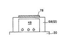
ここで、本発明で用いるマイクロポンプは、図6に示すように、セラミックスから形成されたキャビティ48を内面に有する基体68と、基体12の外面(振動部66)上に膜形成法によって形成された電極75,77及び圧電/電歪層73を備えた圧電/電歪作動部78と、圧電/電歪作動部78によりキャビティ48内に発生した圧力で、キャビティ48内の試料を送受液する少なくとも2つ以上の連結口18と、を備えたものである。 Here, as shown in FIG. 6, the micropump used in the present invention is formed on a base 68 having a
次に、本発明のマイクロリアクターは、第2の基板が、第1の基板の全面(図1参照)又は部分的(図示せず)に貼り合わされ、一体化されていることが好ましい。特に、第2の基板の大きさをマイクロポンプ10の設置に必要最小限の大きさにすることにより、第1の基板(リアクターユニット)からの化学反応の検出や光化学反応を妨げることがないため好ましい。また、本発明のマイクロリアクターは、第2の基板に光学検出を妨げないような貫通穴を適宜設けても良い。 Next, in the microreactor of the present invention, it is preferable that the second substrate is bonded and integrated on the entire surface (see FIG. 1) or partially (not shown) of the first substrate. In particular, the detection of the chemical reaction from the first substrate (reactor unit) and the photochemical reaction are not hindered by setting the size of the second substrate to the minimum necessary size for the installation of the
本発明で用いる第2の基板は、第1の基板の注入口及び/又は送出口の配設可能位置の一部又は全てに、予めマイクロポンプを備えることが好ましく、また、第1の基板の注入口及び/又は送出口の数より多いマイクロポンプを備えていることが好ましい。これは、チャネル(流路)やリアクター(反応槽)のパターンの設計変更により、注入口や送出口の設置個所の変更に柔軟に対応することができるとともに、多品種の第1の基板(リアクターユニット)に柔軟に対応できるからである。 The second substrate used in the present invention preferably includes a micropump in advance at a part or all of the positions where the inlet and / or the outlet of the first substrate can be disposed. Preferably there are more micropumps than the number of inlets and / or outlets. This is because the design change of the pattern of the channel (flow path) and the reactor (reaction tank) can flexibly cope with the change of the installation location of the inlet and the outlet and the first substrate (reactor) of various types. This is because the unit can be flexibly supported.
ここで、本発明で用いるマイクロポンプは、例えば、図7(a)に示すように、マイクロポンプユニット12とサポートユニット20とを接合する場合、接合部が連結口18の断面積×圧力分の力しか掛からないため、マイクロポンプ10を駆動した時に発生する基板12,20同士の引き剥がし力を大幅に低減することができ、基板12,20同士の界面部を構成する接合材(例えば、接着剤)を必要最小限にすることが可能であり、基板12,20同士をより確実に一体化することができる。 Here, in the micropump used in the present invention, for example, as shown in FIG. 7A, when the
一方、従来のマイクロポンプは、例えば、図7(b)に示すように、マイクロポンプユニット12とサポートユニット20とを接合する場合、接合部が、キャビティ48で直接覆われている形になっている。このため、マイクロポンプ10を駆動した場合、キャビティ48内部が増圧され、その圧力がキャビティ48の断面積(サポートユニット20との接触部)全体に伝わるため、接合部に掛かる引き剥がし力が非常に大きく、基板同士の接合部に十分な強度を付与するため、接合部の面積を大きくする必要があるが、基板同士を一体化することが困難であるだけでなく、耐久性を十分に得ることができないという問題点があった。 On the other hand, in the conventional micropump, for example, as shown in FIG. 7B, when the
また、本発明で用いるマイクロポンプは、セラミックス一体構造であるため、剛性が高く、大きな吐出力を発生させた場合であっても、耐久性に優れているだけでなく、圧力を損失させることなく、試料を送受液することができる。このため、本発明で用いるマイクロポンプは、例えば、2μm〜40μmの微小な流路幅を有するチャネルに試料を流す場合に、必要な吐出力を与えるために、好適に用いることができる。 In addition, since the micropump used in the present invention has a ceramic integrated structure, it has high rigidity and is excellent in durability even when a large discharge force is generated, without causing pressure loss. The sample can be sent and received. For this reason, the micropump used in the present invention can be suitably used in order to give a necessary discharge force when a sample is passed through a channel having a minute flow path width of 2 μm to 40 μm, for example.
更に、本発明で用いるマイクロポンプは、圧電/電歪体が電圧信号に応じて瞬時に変形することにより、ポンプ内容積を瞬時に変化させ、吐出力を発生することができるため、送受液可能な複数個のマイクロポンプを、高精度且つ一括して制御することができる。 Furthermore, the micropump used in the present invention can send and receive liquids because the piezoelectric / electrostrictive body can be instantly deformed in response to a voltage signal to instantaneously change the pump internal volume and generate a discharge force. A plurality of micropumps can be controlled with high accuracy and collectively.
尚、本発明で用いるマイクロポンプは、以下に示す用途にも好適に用いることができる。 In addition, the micropump used by this invention can be used suitably also for the use shown below.
(1)DNAマイクロアレイのハイブリダイゼーション
本発明のマイクロポンプは、DNAマイクロアレイのハイブリダイゼーション反応促進に使用することにより、マイクロアレイのハイブリダイゼーション溶液をマイクロチャネル内で撹拌することができるため、ハイブリダイゼーション時間を大幅に短縮することが出来る。(1) Hybridization of DNA microarray The micropump of the present invention can be used to promote the hybridization reaction of a DNA microarray, so that the hybridization solution of the microarray can be agitated in the microchannel. Can be shortened.
ここで、本発明のマイクロポンプは、高剛性なセラミックス一体型ポンプであるため、ポンプの高速駆動(振動)が可能である。これにより、本発明のマイクロポンプは、マイクロチャネル内に高速の水の流れを発生させ、水相の撹拌を促進することができるため、微小な撹拌であっても、通常の分子拡散だけでは達成できない分子の局在を解消することができるとともに、マイクロチャネルの内容積を小さくできるので、ハイブリダイゼーション溶液が少量で済む利点がある。 Here, since the micro pump of the present invention is a highly rigid ceramic integrated pump, the pump can be driven at high speed (vibration). As a result, the micropump of the present invention can generate a high-speed water flow in the microchannel and promote the stirring of the aqueous phase. Therefore, even a minute stirring can be achieved only by ordinary molecular diffusion. Since it is possible to eliminate the localization of molecules that cannot be performed and to reduce the internal volume of the microchannel, there is an advantage that a small amount of hybridization solution is required.
また、本発明のマイクロポンプは、ハイブリダイゼーションを行うマイクロチャネル内に溶液を噴射することもできるため、高速な水流により、ハイブリダイゼーション反応を促進することもできる。 In addition, since the micropump of the present invention can also inject a solution into a microchannel that performs hybridization, the hybridization reaction can be promoted by a high-speed water flow.
以上のことから、本発明のマイクロポンプは、DNAマイクロアレイに適用することにより、反応促進によりハイブリダイゼーション効率を高め、蛍光強度が増大し、コストの削減、データの信頼性向上に大きく寄与することができる。 From the above, by applying the micropump of the present invention to a DNA microarray, the hybridization efficiency is enhanced by promoting the reaction, the fluorescence intensity is increased, and the cost can be greatly reduced and the reliability of data can be greatly improved. it can.
(2)液体クロマトグラフィー(高速液体クロマトグラフィー[HPLC])
本発明のマイクロポンプは、チップ上に形成したマイクロチャネルを利用して微量成分で分析が可能なマイクロHPCL用のポンプとして使用することができる。尚、本発明のマイクロポンプは、定常流を送ることができる(高圧の)送液ポンプとマイクロチャネルとの間に設置する。(2) Liquid chromatography (high performance liquid chromatography [HPLC])
The micropump of the present invention can be used as a micro HPCL pump capable of analyzing with a trace amount component using a microchannel formed on a chip. The micropump of the present invention is installed between a (high pressure) liquid feed pump capable of sending a steady flow and a microchannel.
ここで、本発明のマイクロポンプは、高剛性なセラミックス一体型ポンプであるため、圧電/電歪体(圧電/電歪作動部)に与える電圧パルス信号の周波数を変化させることにより、送液流に振動を加味した変調(モジュレーション)を加えることができる。なお、本発明において、圧電/電歪体は膜型であれば、製造コストや集積度等の点で特に好ましいものではあるが、これに限定されるものではないことは言うまでもない。特にハイブリダイゼーション反応が利用される、DNAマイクロアレイのごとき用途、あるいは液体クロマトグラフィーへの適用の場合は膜型以外の態様が適用可能である。 Here, since the micropump of the present invention is a highly rigid ceramics-integrated pump, by changing the frequency of the voltage pulse signal applied to the piezoelectric / electrostrictive body (piezoelectric / electrostrictive operating unit), It is possible to add modulation that takes vibration into account. In the present invention, if the piezoelectric / electrostrictive body is a film type, it is particularly preferable in terms of manufacturing cost, integration degree, etc., but it goes without saying that the present invention is not limited to this. In particular, for applications such as DNA microarrays where a hybridization reaction is used, or for application to liquid chromatography, embodiments other than the membrane type can be applied.
ここで、ハイブリダイセーション反応が利用される用途、あるいは液体クロマトグラフィーへの適用を考慮した場合、圧電/電歪作動部以外を備えていてもよい。即ち、かかる場合には、マイクロチャネルからなる流路と、該流路に連結されたリアクターと、該流路又はそれに連結されたリアクター内に、試料を送受液する注入口と、該リアクターから反応後の試料を回収する送出口と、を備えた第1の基板に、該注入口及び/又は該送出口に対応するように、少なくとも1つ以上のマイクロポンプが一体形成された第2の基板を貼り合わせ一体化されており、該マイクロポンプが、セラミックスから形成されたキャビティを内面に有する基体と、該基体の外面上に圧力付与手段を備え、該圧力付与手段により該キャビティ内に発生した圧力で、該キャビティ内の該試料を送受液する少なくとも2つ以上の連結口とを備えていればよい。ここで、圧力付与手段とは、例えば圧電/電歪体であり、膜型の圧電/電歪層であるとより好ましいがこれに限定されるものではなく、例えば、多層構造を有するバルク状の圧電/電歪体であっても、静電気力や磁力、気体の加熱による熱膨張を利用するものでも良い。 Here, in consideration of the application in which the hybridization reaction is used, or application to liquid chromatography, a device other than the piezoelectric / electrostrictive operation unit may be provided. That is, in such a case, a flow path composed of a microchannel, a reactor connected to the flow path, an inlet for sending and receiving a sample into the flow path or a reactor connected thereto, and a reaction from the reactor. A second substrate in which at least one or more micropumps are integrally formed on a first substrate provided with a delivery port for recovering a later sample so as to correspond to the injection port and / or the delivery port The micropump includes a base body having a cavity formed of ceramics on the inner surface, and a pressure applying means on the outer surface of the base body, and is generated in the cavity by the pressure applying means. It is only necessary to provide at least two or more connection ports for sending and receiving the sample in the cavity with pressure. Here, the pressure applying means is, for example, a piezoelectric / electrostrictive body, and is more preferably a film-type piezoelectric / electrostrictive layer, but is not limited to this, for example, a bulk-like structure having a multilayer structure. Even a piezoelectric / electrostrictive body may be one that utilizes electrostatic force, magnetic force, or thermal expansion due to gas heating.
例えば、被分析物質が高分子である場合、本発明のマイクロポンプを用いることにより、与えられた振動数に応じて、共振現象が起こり、カラム内を流れる高分子の速度が高分子の物理的な形状の応じて変化するため、カラム内の吸脱着速度が変調され、従来、分子構造のわずかな違いでは分離することができなかった高分子の分離が可能である。また、本発明のマイクロポンプを用いることにより、例えば、被分析物質が高分子である場合、送液流に対して変調を掛けることで、高分子の構造によりマイクロチャネル内を進む速度に差を生じさせることができるため、この速度差を利用して高分子の精密分離も可能である。 For example, when the analyte is a polymer, by using the micropump of the present invention, a resonance phenomenon occurs according to a given frequency, and the speed of the polymer flowing in the column is physically increased. Therefore, the adsorption / desorption rate in the column is modulated, and it is possible to separate polymers that could not be separated by a slight difference in molecular structure. In addition, by using the micropump of the present invention, for example, when the analyte is a polymer, a difference is made in the speed of traveling in the microchannel due to the structure of the polymer by modulating the liquid flow. Therefore, the polymer can be precisely separated using this speed difference.
尚、高速液体クロマトグラフィー(HPLC)とは、混合物中の成分を固定相や移動相との相互作用の差により相互に分離するクロマトグラフィー手法の内、微小粒径の固定相を充填したカラムを使用し、移動相を高圧で送液する液体クロマトグラフィーであり、分離度が高く、分析時間が短い方法である。 High-performance liquid chromatography (HPLC) is a chromatography method that separates components in a mixture from each other by the difference in interaction with the stationary phase and mobile phase. It is a liquid chromatography that uses a mobile phase at a high pressure and has a high resolution and a short analysis time.
次に、マイクロポンプユニットの作製方法について、図6に基づいて詳細に説明する。まず、セラミックス原料からそれぞれ作製された(連結口18が配置された)基板層、(キャビティ48が配置された)スペーサ層、(振動部66を構成する)薄板層を順に積層・一体化することにより、所定の位置にキャビティ48と連結口18が形成された基体68を作製する。 Next, a manufacturing method of the micropump unit will be described in detail based on FIG. First, a substrate layer (with the
尚、本発明で用いるマイクロポンプユニットの材質は、特に限定されないが、所定の化合物で結晶相が部分安定化乃至は完全安定化された酸化ジルコニウムが主成分であることが好ましい。ここで、用語「主成分」とは、材料中で、所望とする機能及び/又は役割を発揮する成分としての働きをする成分をいう。これにより、マイクロポンプユニットは、薄い板厚においても機械的強度および靭性を有利に確保することができると共に、相対的に低作動電圧にて大変位が得られ、しかも速い応答速度と大きな発生力を得ることができる。 The material of the micropump unit used in the present invention is not particularly limited, but it is preferable that the main component is zirconium oxide whose crystal phase is partially stabilized or completely stabilized with a predetermined compound. Here, the term “main component” refers to a component that functions as a component that exhibits a desired function and / or role in a material. As a result, the micropump unit can advantageously ensure mechanical strength and toughness even with a thin plate thickness, and can obtain a large displacement at a relatively low operating voltage. Moreover, it has a fast response speed and a large generated force. Can be obtained.
尚、「部分安定化乃至は完全安定化された酸化ジルコニウム」とは、熱や応力等が加えられた時に結晶変態が部分的に或いは全く起こらないように、結晶層を部分的に或いは完全に安定化せしめた酸化ジルコニウムを含むものである。 Incidentally, “partially stabilized or completely stabilized zirconium oxide” means that the crystal layer is partially or completely prevented from undergoing partial or complete crystal transformation when heat or stress is applied. It contains stabilized zirconium oxide.
この酸化ジルコニウムを安定化する化合物としては、酸化イットリウム、酸化セリウム、酸化マグネシウム、酸化カルシウムがあり、少なくともそのうちの一つの化合物を単体で若しくは組み合わせて添加、含有せしめることにより、酸化ジルコニウムは部分的に或いは完全に安定化されることとなる。更にまた、それぞれの化合物の添加含有量としては、酸化イットリウムに関しては2モル%〜7モル%、酸化セリウムに関しては6モル%〜15モル%、酸化マグネシウム、酸化カルシウムに関しては5モル%〜12モル%とすることが好ましいが、その中でも、特に酸化イットリウムを部分安定化剤として用いることが好ましく、その場合においては2モル%〜7モル%、更に好ましくは2モル%〜4モル%とすることが望ましい。 Examples of the compound that stabilizes zirconium oxide include yttrium oxide, cerium oxide, magnesium oxide, and calcium oxide. By adding and including at least one of these compounds alone or in combination, zirconium oxide is partially incorporated. Or it will be completely stabilized. Furthermore, the added content of each compound is 2 to 7 mol% for yttrium oxide, 6 to 15 mol% for cerium oxide, and 5 to 12 mol for magnesium oxide and calcium oxide. In particular, it is preferable to use yttrium oxide as a partial stabilizer, and in that case, 2 mol% to 7 mol%, more preferably 2 mol% to 4 mol%. Is desirable.
そのような範囲で酸化イットリウムを添加・含有せしめてなる酸化ジルコニウムは、その主たる結晶相が正方晶若しくは主として立方晶と正方晶からなる混晶において部分安定化され、優れた基板特性を与えることとなる。また、その正方晶を安定に存在させ、大きな基板強度が得られる為には、基板の平均結晶粒子径も重要となる。即ち、平均粒子径として、0.05μm〜2μmであることが好ましく、更に好ましくは1μm以下であることが望ましい。 Zirconium oxide in which yttrium oxide is added and contained within such a range is partially stabilized in a tetragonal crystal or a mixed crystal composed mainly of cubic and tetragonal crystals, and gives excellent substrate characteristics. Become. In addition, the average crystal grain size of the substrate is also important in order for the tetragonal crystals to exist stably and to obtain a large substrate strength. That is, the average particle diameter is preferably 0.05 μm to 2 μm, more preferably 1 μm or less.
そして、このような基体68の(振動部66)外面上に、所定の電極膜(上下電極)75,77および圧電/電歪層79が、公知の各種の膜形成法、例えば、スクリーン印刷、スプレー、ディッピング、塗布等の厚膜形成手法、イオンビーム、スパッタリング、真空蒸着、イオンプレーティング、CVD、メッキ等の薄膜形成手法によって形成されることとなる。尚、それらの膜形成は、基体68の焼結前に行なうことも、或いは焼結後に行なうことも可能である。 Then, predetermined electrode films (upper and lower electrodes) 75 and 77 and a piezoelectric / electrostrictive layer 79 are formed on the outer surface of the (vibrating portion 66) of such a
また、このようにして第2の基板(基体68)上に膜形成されたそれぞれの膜(電極膜75,77および圧電/電歪層79)は、必要に応じて熱処理されることとなるが、かかる熱処理は、それぞれの膜形成の都度、行なっても良く、或いは全部の膜を形成した後、同時に行なっても良い。更に、電極膜75,77の間の絶縁信頼性を向上させるために、必要に応じて、隣合う圧電/電歪層79,79の間に絶縁樹脂膜を形成しても良い。 In addition, the respective films (
また、かかる圧電/電歪作動部を構成する電極膜75,77の材料としては、熱処理温度並びに焼成温度程度の高温酸化雰囲気に耐えられる導体であれば、特に規制されるものではなく、例えば金属単体であっても、合金であっても良く、また絶縁性セラミックスやガラス等と、金属や合金との混合物であっても、更には導電性セラミックスであっても、何等差し支えない。より好ましくは、白金、パラジウム、ロジウム等の高融点貴金属類、或いは銀−パラジウム、銀−白金、白金−パラジウム等の合金を主成分とする電極材料が好適に用いられる。 Further, the material of the
また、圧電/電歪作動部を構成する圧電/電歪層79の材料としては、圧電或いは電歪効果等の電界誘起歪を示す材料であれば、何れの材料であっても採用され得るものであり、結晶質の材料であっても、非晶質の材料であっても良く、また半導体材料であっても、誘電体セラミックス材料や強誘電体セラミックス材料であっても、何等差し支えなく、更には分極処理が必要な材料であっても、またそれが不必要な材料であっても良いのである。 In addition, as a material of the piezoelectric / electrostrictive layer 79 constituting the piezoelectric / electrostrictive operating portion, any material can be adopted as long as it is a material exhibiting electric field induced strain such as piezoelectric or electrostrictive effect. It may be a crystalline material, an amorphous material, a semiconductor material, a dielectric ceramic material or a ferroelectric ceramic material, and there is no problem. Further, it may be a material that requires a polarization treatment or an unnecessary material.
更に、本発明に用いられる圧電/電歪材料としては、好ましくは、ジルコン酸チタン酸鉛(PZT系)を主成分とする材料、マグネシウムニオブ酸鉛(PMN系)を主成分とする材料、ニッケルニオブ酸鉛(PNN系)を主成分とする材料、マンガンニオブ酸鉛を主成分とする材料、アンチモンスズ酸鉛を主成分とする材料、亜鉛ニオブ酸鉛を主成分とする材料、チタン酸鉛を主成分とする材料、更にはこれらの複合材料等が用いられる。 Furthermore, the piezoelectric / electrostrictive material used in the present invention is preferably a material mainly composed of lead zirconate titanate (PZT), a material mainly composed of lead magnesium niobate (PMN), nickel Materials based on lead niobate (PNN), materials based on lead manganese niobate, materials based on lead antimony stannate, materials based on lead zinc niobate, lead titanate As a main component, these composite materials and the like are used.
また、このような圧電/電歪材料に、ランタン、バリウム、ニオブ、亜鉛、セリウム、カドミウム、クロム、コバルト、ストロンチウム、アンチモン、鉄、イットリウム、タンタル、タングステン、ニッケル、マンガン等の酸化物やそれらの他の化合物を添加物として含有せしめた材料、例えば、PLZT系となるように、前記PZT系を主成分とする材料に上記の如き所定の添加物を適宜に加えたものであっても、何等差し支えない。 In addition, such piezoelectric / electrostrictive materials include lanthanum, barium, niobium, zinc, cerium, cadmium, chromium, cobalt, strontium, antimony, iron, yttrium, tantalum, tungsten, nickel, manganese and other oxides and their A material in which another compound is added as an additive, for example, a material having the PZT system as a main component so as to be a PLZT system, and a predetermined additive as described above is appropriately added. There is no problem.
尚、上記の如くして形成される電極膜75,77と圧電/電歪膜(層)78から構成される圧電/電歪作動部の厚さとしては、一般に100μm以下とされ、また電極膜75,77の厚さとしては、一般に20μm以下、好ましくは5μm以下とされることが望ましく、更に圧電/電歪膜79の厚さとしては、低作動電圧で大きな変位等を得るために、好ましくは50μm以下、更に好ましくは3μm以上40μm以下とされることが望ましい。加えて、かかる圧電/電歪素子78は、膜形成法によって形成されることから、膜形成プロセスの利点により、基体68上に多数個、微細な間隔を隔てて、接着剤等を用いずに同時に且つ容易に形成することができる。 Incidentally, the thickness of the piezoelectric / electrostrictive operating portion composed of the
前述のように、本発明のマイクロリアクターは、例えば、図2に示すように、第1の基板2に、別途作製した第2の基板30を貼り合わせ、一体化することにより得ることができる。 As described above, the microreactor of the present invention can be obtained, for example, by bonding and integrating the separately manufactured
このとき、本発明のマイクロリアクターは、例えば、図8に示すように、第2の基板32としては、また、以下に例挙する部材の少なくとも1個の部材を含むものが使用可能である:マイクロポンプユニット12と、各マイクロポンプ10の出口形状をそれぞれ調整するノズル孔29と、各マイクロポンプ10に試料を流通(供給及び/又は排出)させる流路27,28とを備えたサポートユニット20。更に詳細には、サポートユニット(補助基板)20は、図8に示すように、マイクロポンプユニット12に配設されたマイクロポンプ10に試料を流通(供給及び/又は排出)させる流路17を流路27と連通させる。 At this time, as the microreactor of the present invention, for example, as shown in FIG. 8, as the
次いで、流路27−キャビティ48間及びキャビティ48−流路28間を、サポートユニット20のマイクロポンプユニット12に対する重ね合わせ面に開口するように、且つキャビティ48の直下に位置するように連通孔をそれぞれ配設することにより、「流通孔16−流路17−流路27−キャビティ48−流路28−ノズル孔29」と連通させることができる。 Next, the communication holes are formed so as to open between the
尚、本発明で用いるサポートユニット20の材質は、特に限定されないが、マイクロポンプユニット12やリアクターユニット(第1の基板)と同一のものを用いることが好ましい。これにより、本発明で用いるサポートユニット20は、キャビティ48内におけるの試料の流通をスムーズに行うことができるとともに、リアクターユニット2への送液口がノズル孔29となっているので、試料を加圧して噴出させることができる。 The material of the
また、本発明で用いるサポートユニット20は、マイクロポンプユニット12の仕様を替えることなく、サポートユニット20の変更のみで、リアクターユニットの設計変更に適宜対応できるという利点を有する。尚、本発明で用いるサポートユニットは、例えば、図8に示すように、マイクロポンプ10への試料の逆流を防止したい場合、その内部に逆止弁21を配設することが好ましい。 Further, the
また、本発明で用いる第2の基板は、例えば、図3に示すように、マイクロポンプユニットにサポートユニットの機能を付与したものであることが、コンパクト化(薄肉化)することができるとともに、ハンドリング性にも優れている(図2参照)。 In addition, the second substrate used in the present invention can be made compact (thinned), for example, as shown in FIG. 3, by adding the function of the support unit to the micropump unit. It also has excellent handling properties (see FIG. 2).
更に、本発明のマイクロリアクターは、第1の基板と第2の基板とを、例えば、以下に示す方法を用いて貼り合わせ、一体化することができる。 Furthermore, in the microreactor of the present invention, the first substrate and the second substrate can be bonded and integrated using, for example, the method shown below.
(1)第1の基板と第2の基板との間に接着シートを介在させ、この接着シートにより接合させる。(1) An adhesive sheet is interposed between the first substrate and the second substrate, and bonded by this adhesive sheet.
このとき、(1)の方法では、接着シートの替わりに、接着剤を接合面にスクリーン印刷法により形成させたものを用いてもよい。また、(1)の方法では、接着後、接着層を強化するため紫外線硬化型アクリル樹脂を流し込んでもよい。 At this time, in the method (1), instead of the adhesive sheet, an adhesive formed on the joint surface by a screen printing method may be used. In the method (1), after bonding, an ultraviolet curable acrylic resin may be poured to reinforce the adhesive layer.
(2)第1の基板と第2の基板との間にスペーサーを設置するなどして一定のギャップを形成した後、アクリル樹脂を側面より流し込み、このアクリル樹脂を用いて接合させる。(2) After a certain gap is formed by installing a spacer between the first substrate and the second substrate, an acrylic resin is poured from the side surface and bonded using this acrylic resin.
このとき、接合面積が大きい場合は、基板に貫通穴を開け、接合部に残留する空気を接合部の外に排出することが好ましい。また、(2)の方法では、接合面積、材料に応じてアクリル樹脂の粘性を調整することが好ましい。更に、(2)の方法では、アクリル樹脂を硬化させるための紫外線硬化パワーは最適なものを選ぶことが好ましい。 これは、パワーが小さすぎると硬化時間が掛かりすぎ、パワーが多き過ぎると急激な硬化反応が起こり接合部にクラックが入ることがあるからである。 At this time, when the bonding area is large, it is preferable to make a through hole in the substrate and discharge the air remaining in the bonding portion to the outside of the bonding portion. In the method (2), it is preferable to adjust the viscosity of the acrylic resin according to the bonding area and material. Further, in the method (2), it is preferable to select an optimum ultraviolet curing power for curing the acrylic resin. This is because if the power is too low, it takes too much curing time, and if the power is too high, a rapid curing reaction occurs and cracks may occur in the joint.
尚、(2)の方法では、スクリーン印刷法によりアクリル樹脂流し込みのためのギャップを形成してもよい。 In the method (2), a gap for casting the acrylic resin may be formed by screen printing.
尚、使用され得る接着剤としては、ビニル系、アクリル系、ポリアミド系、フェノール系、レゾルシノール系、ユリア系、メラミン系、ポリエステル系、エポキシ系、フラン系、ポリウレタン系、シリコーン系、ゴム系、ポリイミド系、ポリオレフィン系等の何れでも良い。但し、用いる試料に対する耐久性のある接着剤を選択する。 Examples of adhesives that can be used include vinyl, acrylic, polyamide, phenol, resorcinol, urea, melamine, polyester, epoxy, furan, polyurethane, silicone, rubber, polyimide Any of the type, polyolefin type, etc. may be used. However, a durable adhesive for the sample to be used is selected.
また、接着剤の形態は、量産性の点から、ディスペンサーによる塗布が可能か、或いはスクリーン印刷が可能な高粘性のペーストタイプか、打抜き加工が可能なシートタイプが優れており、また加熱時間の短いホットメルト接着型か、或いは室温硬化接着型がより望ましい。更に、高粘性のペーストタイプとしては、本来の接着剤にフィラーを混入して粘度を上げたものも用いることができる。 In addition, from the viewpoint of mass productivity, the adhesive can be applied by a dispenser, or a highly viscous paste type that can be screen-printed, or a sheet type that can be punched, and has an excellent heating time. A short hot melt adhesive type or a room temperature cure adhesive type is more desirable. Furthermore, as a high-viscosity paste type, a paste in which a filler is mixed into the original adhesive to increase the viscosity can be used.
以上の点、および特に試料(水系)に対する耐久性の観点からは、スクリーン印刷が可能な弾性エポキシ接着剤やシリコーン系接着剤、或いは打抜き加工が可能なシート形状ホットメルトタイプのポリオレフィン系接着剤やポリエステル系接着剤等が、特に好適に用いられることとなる。なお、それらの各種接着剤を、接着面の一部分と他の部分とに、それぞれ使い分けて、適用することも可能である。 From the above point of view, and particularly from the viewpoint of durability against a sample (water-based), an elastic epoxy adhesive or a silicone-based adhesive capable of screen printing, or a sheet-shaped hot melt type polyolefin-based adhesive capable of punching, A polyester adhesive or the like is particularly preferably used. In addition, it is also possible to use these various adhesives separately for a part of the bonding surface and another part.
更に、本発明のマイクロリアクターは、第1の基板(リアクターユニット)と第2の基板(マイクロポンプユニット)との貼り合わせ界面部(接合部)の厚さは、0.1〜10μmであることが好ましい。これは、接合層の厚さが0.1μm未満である場合、基板自身のうねり、表面粗さが吸収できない程、薄くなった場合、基板同士が接触し、接合層が事実上存在しない可能性があるため、接合強度が実質上弱くなってしまうからである。一方、接合層の厚さが10μmを超過する場合、セラミックスの剛性が高くても、接合層がやわらかく、厚みが厚ければ圧力を吸収してしまう。尚、接合の一般論としては、(基板が理想的な平面であるときの)接合層は薄いほうが望ましく、本来、接合層は、強度的にも基板より弱いので、できるだけ無いほうが好ましい。このため、接合層を用いる場合、なるべく薄く(小さく)して、接合層からの破損を避けることが必要不可欠である。 Furthermore, in the microreactor of the present invention, the thickness of the bonding interface portion (bonding portion) between the first substrate (reactor unit) and the second substrate (micropump unit) is 0.1 to 10 μm. Is preferred. This is because, when the thickness of the bonding layer is less than 0.1 μm, the substrates may come into contact with each other when the substrate itself becomes so thin that the undulation and surface roughness of the substrate cannot be absorbed. This is because the bonding strength is substantially weakened. On the other hand, when the thickness of the bonding layer exceeds 10 μm, even if the ceramic has high rigidity, the bonding layer is soft, and if the thickness is thick, the pressure is absorbed. Note that, as a general theory of bonding, it is desirable that the bonding layer (when the substrate is an ideal plane) is thin, and the bonding layer is inherently weaker than the substrate in terms of strength. For this reason, when using a joining layer, it is indispensable to make it as thin (small) as possible to avoid damage from the joining layer.
以下、本発明を実施例に基づいて更に詳細に説明するが、本発明はこれらの実施例に限られるものではない。 EXAMPLES Hereinafter, although this invention is demonstrated further in detail based on an Example, this invention is not limited to these Examples.
図1に示すように、12個の単位リアクターが形成された第2の基板30を用いた縦:20mm×横:15mm×厚さ:3mmのマイクロリアクターを、本発明の製造方法に基づいて製造した。 As shown in FIG. 1, a microreactor having a length: 20 mm × width: 15 mm × thickness: 3 mm using the
ここで、単位リアクターとは、図2に示すように、セラミックス一体型のマイクロポンプ10を3個有し、それぞれのポンプが流路5,7(流路幅:50μm)を介して1つのリアクター6に連結されており、試料の供給と回収が行われるものである。 Here, as shown in FIG. 2, the unit reactor has three ceramic-integrated
次に、得られたマイクロリアクターの基本性能の評価を行った。 Next, the basic performance of the obtained microreactor was evaluated.
(比較例)
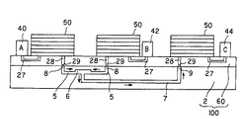
図9に示すように、1個の単位リアクターが形成された縦:10mm×横:30mm×厚さ:3mmのマイクロリアクターを、既存の製造方法で製造した。(Comparative example)
As shown in FIG. 9, a microreactor having a length: 10 mm × width: 30 mm × thickness: 3 mm in which one unit reactor was formed was manufactured by an existing manufacturing method.
ここで、単位リアクターとは、図10に示すように、ダイヤフラムポンプ50を3個有し、それぞれのポンプが流路5,7(流路幅:50μm)を介して1つのリアクター6に連結されており、試料の供給と回収が行われるものである。 Here, as shown in FIG. 10, the unit reactor has three
次に、得られたマイクロリアクターの基本性能の評価を行った。 Next, the basic performance of the obtained microreactor was evaluated.
(考察)
実施例では、図1に示すように、比較例(図9参照)と比較して、単位面積当たりのマイクロポンプ10、即ち単位リアクターの集積度が非常に高く、コストパフォーマンスに優れているだけでなく、リアクターユニット2の設計に応じて、マイクロポンプ10を適宜連結又は分離させることにより、様々な反応系のマイクロリアクターを容易に作製することができた。(Discussion)
In the embodiment, as shown in FIG. 1, compared with the comparative example (see FIG. 9), the degree of integration of the micropump 10 per unit area, that is, the unit reactor is very high, and only the cost performance is excellent. In addition, according to the design of the
以上説明した通り、本発明のマイクロリアクターは、チャネル(流路)内への吐出力に優れ、且つ瞬時に送受液を精密な精度で制御することができる複数個のマイクロポンプを集積化できるとともに、集積化されたマイクロポンプが一体形成されたマイクロポンプユニットと、チャネル(流路)、リアクター(反応槽)、注入口及び送出口を主に備えたリアクターユニットとを別々に製造後、貼り合わせることにより、生産性及び汎用性に優れている。 As described above, the microreactor of the present invention is capable of integrating a plurality of micropumps that are excellent in discharging force into a channel (flow path) and that can instantaneously control the sending and receiving liquid with high precision. A micropump unit in which integrated micropumps are integrally formed and a reactor unit mainly including a channel (flow path), a reactor (reaction vessel), an inlet and an outlet are separately manufactured and bonded together. Therefore, it is excellent in productivity and versatility.
Claims (8)
Translated fromJapanese該マイクロポンプが、セラミックスから形成されたキャビティを内面に有する基体と、
該基体の外面上に膜形成法によって形成された電極及び圧電/電歪層を備えた圧電/電歪作動部と、
該圧電/電歪作動部により該キャビティ内に発生した圧力で、該キャビティ内の該試料を送受液する少なくとも2つ以上の連結口と、
を備えることを特徴とするマイクロリアクター。A flow path comprising a microchannel, a reactor connected to the flow path, an inlet for sending and receiving a sample in the flow path or a reactor connected thereto, and a transport for collecting a sample after reaction from the reactor. And a second substrate integrally formed with at least one micropump so as to correspond to the inlet and / or the outlet. A microreactor,
A substrate having a cavity formed on the inner surface, the micropump comprising ceramics;
A piezoelectric / electrostrictive operating portion comprising an electrode formed on the outer surface of the substrate by a film forming method and a piezoelectric / electrostrictive layer;
At least two or more connection ports for sending and receiving the sample in the cavity with the pressure generated in the cavity by the piezoelectric / electrostrictive actuator;
A microreactor comprising:
Applications Claiming Priority (3)
| Application Number | Priority Date | Filing Date | Title |
|---|---|---|---|
| US48635303P | 2003-07-11 | 2003-07-11 | |
| US60/486,353 | 2003-07-11 | ||
| PCT/JP2004/009556WO2005005043A2 (en) | 2003-07-11 | 2004-07-06 | Microreactor |
Publications (1)
| Publication Number | Publication Date |
|---|---|
| JPWO2005005043A1true JPWO2005005043A1 (en) | 2007-09-20 |
Family
ID=34062122
Family Applications (1)
| Application Number | Title | Priority Date | Filing Date |
|---|---|---|---|
| JP2005511511APendingJPWO2005005043A1 (en) | 2003-07-11 | 2004-07-06 | Microreactor |
Country Status (4)
| Country | Link |
|---|---|
| EP (1) | EP1645329A4 (en) |
| JP (1) | JPWO2005005043A1 (en) |
| CN (1) | CN100404121C (en) |
| WO (1) | WO2005005043A2 (en) |
Families Citing this family (13)
| Publication number | Priority date | Publication date | Assignee | Title |
|---|---|---|---|---|
| JP2007136292A (en)* | 2005-11-15 | 2007-06-07 | National Institute Of Advanced Industrial & Technology | Method for manufacturing microchannel structure, microchannel structure, and microreactor |
| JP2007147456A (en) | 2005-11-28 | 2007-06-14 | Seiko Epson Corp | Microfluidic system, sample analyzer, and target substance detection or measurement method |
| US10753927B2 (en) | 2006-09-22 | 2020-08-25 | ALERE TECHNOLOGIES GmbH | Methods for detecting an analyte |
| US20100018584A1 (en)* | 2008-07-28 | 2010-01-28 | Technion Research & Development Foundation Ltd. | Microfluidic system and method for manufacturing the same |
| DE102009013913A1 (en)* | 2009-03-19 | 2010-09-23 | J. Eberspächer GmbH & Co. KG | Dosierpumpanordnung |
| CN101698146B (en)* | 2009-09-24 | 2011-10-26 | 复旦大学附属肿瘤医院 | Microscale reactor for synthesizing radioactive drug and application thereof |
| JP5982118B2 (en)* | 2011-12-05 | 2016-08-31 | 株式会社菊池製作所 | Micro-diaphragm pump, its mounting structure and pump mounting board |
| WO2016005557A1 (en)* | 2014-07-10 | 2016-01-14 | Ceramtec Gmbh | Laminated ceramic molded article having recesses |
| CN104481850B (en)* | 2014-11-13 | 2016-08-03 | 常州大学 | A kind of optical drive micro-fluid pump |
| US11053154B2 (en) | 2015-08-13 | 2021-07-06 | Corning Incorporated | Additive manufacturing processes and manufactured article |
| WO2018057005A1 (en)* | 2016-09-23 | 2018-03-29 | Hewlett-Packard Development Company, L.P. | Microfluidic device |
| EP4000726A4 (en)* | 2019-08-22 | 2023-04-26 | M.O.P Co., Ltd | CERAMIC MICROFLUID REACTOR AND METHOD FOR ITS MANUFACTURE |
| WO2023229599A1 (en)* | 2022-05-26 | 2023-11-30 | Hewlett-Packard Development Company, L.P. | One-time-open microfluidic valves |
Citations (8)
| Publication number | Priority date | Publication date | Assignee | Title |
|---|---|---|---|---|
| JPH0486388A (en)* | 1990-07-27 | 1992-03-18 | Seiko Epson Corp | Flow path configuration of piezoelectric micropump |
| JP2000279796A (en)* | 1999-03-31 | 2000-10-10 | Ngk Insulators Ltd | Powder manufacturing device |
| JP2001228159A (en)* | 2000-02-14 | 2001-08-24 | Seiko Epson Corp | Micro reactor |
| JP2002085961A (en)* | 2000-09-13 | 2002-03-26 | Inst Of Physical & Chemical Res | REACTOR AND ITS MANUFACTURING METHOD |
| JP2002202061A (en)* | 2000-12-28 | 2002-07-19 | Matsushita Electric Ind Co Ltd | Small pump and cooling system |
| JP2003072061A (en)* | 2001-04-06 | 2003-03-12 | Ngk Insulators Ltd | Cell driving type micro-pump member and method of manufacturing the same |
| WO2003033399A1 (en)* | 2001-10-15 | 2003-04-24 | Ngk Insulators, Ltd. | Drive device |
| JP2004517335A (en)* | 2000-12-14 | 2004-06-10 | アドヴァリティクス アーゲー | Method and apparatus for manipulating small volumes of liquid |
Family Cites Families (9)
| Publication number | Priority date | Publication date | Assignee | Title |
|---|---|---|---|---|
| JP2842448B2 (en)* | 1989-07-11 | 1999-01-06 | 日本碍子株式会社 | Piezoelectric / electrostrictive film type actuator |
| DE69026765T2 (en)* | 1989-07-11 | 1996-10-24 | Ngk Insulators Ltd | Piezoelectric / electrostrictive actuator containing a piezoelectric / electrostrictive film |
| US5637469A (en)* | 1992-05-01 | 1997-06-10 | Trustees Of The University Of Pennsylvania | Methods and apparatus for the detection of an analyte utilizing mesoscale flow systems |
| JP3283386B2 (en)* | 1993-09-13 | 2002-05-20 | 日本碍子株式会社 | Piezoelectric film type element, its processing method and its driving method |
| US5856174A (en)* | 1995-06-29 | 1999-01-05 | Affymetrix, Inc. | Integrated nucleic acid diagnostic device |
| EP1314472A1 (en)* | 1998-10-09 | 2003-05-28 | Motorola, Inc. | Integrated multilayered microfluidic devices and methods for making the same |
| US6362558B1 (en)* | 1999-12-24 | 2002-03-26 | Kansai Research Institute | Piezoelectric element, process for producing the same and ink jet recording head |
| US6752601B2 (en)* | 2001-04-06 | 2004-06-22 | Ngk Insulators, Ltd. | Micropump |
| US6761028B2 (en)* | 2001-10-15 | 2004-07-13 | Ngk Insulators, Ltd. | Drive device |
- 2004
- 2004-07-06JPJP2005511511Apatent/JPWO2005005043A1/enactivePending
- 2004-07-06CNCNB2004800198534Apatent/CN100404121C/ennot_activeExpired - Fee Related
- 2004-07-06EPEP04747025Apatent/EP1645329A4/ennot_activeWithdrawn
- 2004-07-06WOPCT/JP2004/009556patent/WO2005005043A2/enactiveApplication Filing
Patent Citations (8)
| Publication number | Priority date | Publication date | Assignee | Title |
|---|---|---|---|---|
| JPH0486388A (en)* | 1990-07-27 | 1992-03-18 | Seiko Epson Corp | Flow path configuration of piezoelectric micropump |
| JP2000279796A (en)* | 1999-03-31 | 2000-10-10 | Ngk Insulators Ltd | Powder manufacturing device |
| JP2001228159A (en)* | 2000-02-14 | 2001-08-24 | Seiko Epson Corp | Micro reactor |
| JP2002085961A (en)* | 2000-09-13 | 2002-03-26 | Inst Of Physical & Chemical Res | REACTOR AND ITS MANUFACTURING METHOD |
| JP2004517335A (en)* | 2000-12-14 | 2004-06-10 | アドヴァリティクス アーゲー | Method and apparatus for manipulating small volumes of liquid |
| JP2002202061A (en)* | 2000-12-28 | 2002-07-19 | Matsushita Electric Ind Co Ltd | Small pump and cooling system |
| JP2003072061A (en)* | 2001-04-06 | 2003-03-12 | Ngk Insulators Ltd | Cell driving type micro-pump member and method of manufacturing the same |
| WO2003033399A1 (en)* | 2001-10-15 | 2003-04-24 | Ngk Insulators, Ltd. | Drive device |
Also Published As
| Publication number | Publication date |
|---|---|
| EP1645329A4 (en) | 2010-05-19 |
| CN100404121C (en) | 2008-07-23 |
| WO2005005043A2 (en) | 2005-01-20 |
| WO2005005043A3 (en) | 2005-04-14 |
| CN1822897A (en) | 2006-08-23 |
| EP1645329A2 (en) | 2006-04-12 |
Similar Documents
| Publication | Publication Date | Title |
|---|---|---|
| JPWO2005005043A1 (en) | Microreactor | |
| US6852291B1 (en) | Hybrid valve apparatus and method for fluid handling | |
| US5877580A (en) | Micromachined chemical jet dispenser | |
| US8393356B2 (en) | Device for controlling fluid motion into micro/nanochannels by means of surface acoustic waves | |
| US20020185184A1 (en) | Microfluidic synthesis devices and methods | |
| CN112138731B (en) | Microfluidic device, its manufacturing method, and manufacturing device | |
| US20100302322A1 (en) | Micromachined fluid ejector | |
| CN102459565A (en) | Fluidic devices with diaphragm valves | |
| JP2005537923A (en) | Mounting of microfluidic components in a microfluidic system | |
| JP4221184B2 (en) | Micro chemical chip | |
| GB2386846A (en) | Tensioning the laminates of a fluid device using a rim | |
| WO2008150210A1 (en) | Micropump | |
| US7504070B2 (en) | Micro reactor | |
| JP2004351309A (en) | Microchemical chip and method for manufacturing the same | |
| JP2004354180A (en) | Micro chemical chip | |
| WO2008030088A2 (en) | Assembly of at least one microfluidic device and a mounting piece, mounting piece and methods for manufacture and use of such an assembly | |
| Bergkvist et al. | Miniaturized flowthrough microdispenser with piezoceramic tripod actuation | |
| KR100826584B1 (en) | Fluid Channeling Actuators for Biochip Analysis | |
| CN1319617C (en) | Active mode mixer for microflow and mixing method | |
| CN103055975A (en) | Micro-fluid self-driven micro-fluidic chip with temperature response and preparation method thereof | |
| US20080213134A1 (en) | Device for Supplying Fluids, Method for Producing this Device, and Pipette Comprising Such a Device | |
| JP4605044B2 (en) | Droplet ejection device, defoaming method, and microarray manufacturing method | |
| EP1780548A1 (en) | Microchemical chip | |
| JP2002048071A (en) | Micro fluid system | |
| JP4439407B2 (en) | Micro chemical chip |
Legal Events
| Date | Code | Title | Description |
|---|---|---|---|
| A131 | Notification of reasons for refusal | Free format text:JAPANESE INTERMEDIATE CODE: A131 Effective date:20100223 | |
| A521 | Written amendment | Free format text:JAPANESE INTERMEDIATE CODE: A523 Effective date:20100423 | |
| A131 | Notification of reasons for refusal | Free format text:JAPANESE INTERMEDIATE CODE: A131 Effective date:20110426 | |
| A02 | Decision of refusal | Free format text:JAPANESE INTERMEDIATE CODE: A02 Effective date:20111011 |