JPWO2005004227A1 - Displacement amount detection method and displacement amount correction method for thin plate-like object - Google Patents
Displacement amount detection method and displacement amount correction method for thin plate-like objectDownload PDFInfo
- Publication number
- JPWO2005004227A1 JPWO2005004227A1JP2005503395AJP2005503395AJPWO2005004227A1JP WO2005004227 A1JPWO2005004227 A1JP WO2005004227A1JP 2005503395 AJP2005503395 AJP 2005503395AJP 2005503395 AJP2005503395 AJP 2005503395AJP WO2005004227 A1JPWO2005004227 A1JP WO2005004227A1
- Authority
- JP
- Japan
- Prior art keywords
- thin plate
- displacement amount
- support arm
- displacement
- end effector
- Prior art date
- Legal status (The legal status is an assumption and is not a legal conclusion. Google has not performed a legal analysis and makes no representation as to the accuracy of the status listed.)
- Granted
Links
- 238000001514detection methodMethods0.000titleclaimsabstractdescription43
- 238000012937correctionMethods0.000titleclaimsabstractdescription7
- 238000006073displacement reactionMethods0.000titleclaimsdescription50
- 238000000034methodMethods0.000titleclaimsdescription14
- 239000012636effectorSubstances0.000claimsabstractdescription32
- 239000000463materialSubstances0.000claimsdescription7
- 238000012546transferMethods0.000description41
- 238000012545processingMethods0.000description20
- 230000003287optical effectEffects0.000description14
- 238000004364calculation methodMethods0.000description7
- 238000010586diagramMethods0.000description6
- 230000006872improvementEffects0.000description6
- 238000005259measurementMethods0.000description5
- 239000000758substrateSubstances0.000description5
- 230000009471actionEffects0.000description4
- 230000008569processEffects0.000description3
- 230000005540biological transmissionEffects0.000description2
- 238000005401electroluminescenceMethods0.000description2
- 239000004973liquid crystal related substanceSubstances0.000description2
- 230000009467reductionEffects0.000description2
- 239000004065semiconductorSubstances0.000description2
- NAWXUBYGYWOOIX-SFHVURJKSA-N(2s)-2-[[4-[2-(2,4-diaminoquinazolin-6-yl)ethyl]benzoyl]amino]-4-methylidenepentanedioic acidChemical compoundC1=CC2=NC(N)=NC(N)=C2C=C1CCC1=CC=C(C(=O)N[C@@H](CC(=C)C(O)=O)C(O)=O)C=C1NAWXUBYGYWOOIX-SFHVURJKSA-N0.000description1
- 230000000903blocking effectEffects0.000description1
- 230000003139buffering effectEffects0.000description1
- 238000007796conventional methodMethods0.000description1
- 238000012423maintenanceMethods0.000description1
- 238000004519manufacturing processMethods0.000description1
- 230000007246mechanismEffects0.000description1
Images


Classifications
- H—ELECTRICITY
- H01—ELECTRIC ELEMENTS
- H01L—SEMICONDUCTOR DEVICES NOT COVERED BY CLASS H10
- H01L21/00—Processes or apparatus adapted for the manufacture or treatment of semiconductor or solid state devices or of parts thereof
- H01L21/67—Apparatus specially adapted for handling semiconductor or electric solid state devices during manufacture or treatment thereof; Apparatus specially adapted for handling wafers during manufacture or treatment of semiconductor or electric solid state devices or components ; Apparatus not specifically provided for elsewhere
- H01L21/67005—Apparatus not specifically provided for elsewhere
- H01L21/67242—Apparatus for monitoring, sorting or marking
- H01L21/67259—Position monitoring, e.g. misposition detection or presence detection
- B—PERFORMING OPERATIONS; TRANSPORTING
- B25—HAND TOOLS; PORTABLE POWER-DRIVEN TOOLS; MANIPULATORS
- B25J—MANIPULATORS; CHAMBERS PROVIDED WITH MANIPULATION DEVICES
- B25J19/00—Accessories fitted to manipulators, e.g. for monitoring, for viewing; Safety devices combined with or specially adapted for use in connection with manipulators
- B25J19/02—Sensing devices
- B25J19/021—Optical sensing devices
- H—ELECTRICITY
- H01—ELECTRIC ELEMENTS
- H01L—SEMICONDUCTOR DEVICES NOT COVERED BY CLASS H10
- H01L21/00—Processes or apparatus adapted for the manufacture or treatment of semiconductor or solid state devices or of parts thereof
- H01L21/67—Apparatus specially adapted for handling semiconductor or electric solid state devices during manufacture or treatment thereof; Apparatus specially adapted for handling wafers during manufacture or treatment of semiconductor or electric solid state devices or components ; Apparatus not specifically provided for elsewhere
- H01L21/67005—Apparatus not specifically provided for elsewhere
- H01L21/67242—Apparatus for monitoring, sorting or marking
- H01L21/67259—Position monitoring, e.g. misposition detection or presence detection
- H01L21/67265—Position monitoring, e.g. misposition detection or presence detection of substrates stored in a container, a magazine, a carrier, a boat or the like
- H—ELECTRICITY
- H01—ELECTRIC ELEMENTS
- H01L—SEMICONDUCTOR DEVICES NOT COVERED BY CLASS H10
- H01L21/00—Processes or apparatus adapted for the manufacture or treatment of semiconductor or solid state devices or of parts thereof
- H01L21/67—Apparatus specially adapted for handling semiconductor or electric solid state devices during manufacture or treatment thereof; Apparatus specially adapted for handling wafers during manufacture or treatment of semiconductor or electric solid state devices or components ; Apparatus not specifically provided for elsewhere
- H01L21/68—Apparatus specially adapted for handling semiconductor or electric solid state devices during manufacture or treatment thereof; Apparatus specially adapted for handling wafers during manufacture or treatment of semiconductor or electric solid state devices or components ; Apparatus not specifically provided for elsewhere for positioning, orientation or alignment
- H01L21/681—Apparatus specially adapted for handling semiconductor or electric solid state devices during manufacture or treatment thereof; Apparatus specially adapted for handling wafers during manufacture or treatment of semiconductor or electric solid state devices or components ; Apparatus not specifically provided for elsewhere for positioning, orientation or alignment using optical controlling means
- H—ELECTRICITY
- H01—ELECTRIC ELEMENTS
- H01L—SEMICONDUCTOR DEVICES NOT COVERED BY CLASS H10
- H01L21/00—Processes or apparatus adapted for the manufacture or treatment of semiconductor or solid state devices or of parts thereof
- H01L21/67—Apparatus specially adapted for handling semiconductor or electric solid state devices during manufacture or treatment thereof; Apparatus specially adapted for handling wafers during manufacture or treatment of semiconductor or electric solid state devices or components ; Apparatus not specifically provided for elsewhere
- H01L21/683—Apparatus specially adapted for handling semiconductor or electric solid state devices during manufacture or treatment thereof; Apparatus specially adapted for handling wafers during manufacture or treatment of semiconductor or electric solid state devices or components ; Apparatus not specifically provided for elsewhere for supporting or gripping
- H01L21/687—Apparatus specially adapted for handling semiconductor or electric solid state devices during manufacture or treatment thereof; Apparatus specially adapted for handling wafers during manufacture or treatment of semiconductor or electric solid state devices or components ; Apparatus not specifically provided for elsewhere for supporting or gripping using mechanical means, e.g. chucks, clamps or pinches
- H01L21/68707—Apparatus specially adapted for handling semiconductor or electric solid state devices during manufacture or treatment thereof; Apparatus specially adapted for handling wafers during manufacture or treatment of semiconductor or electric solid state devices or components ; Apparatus not specifically provided for elsewhere for supporting or gripping using mechanical means, e.g. chucks, clamps or pinches the wafers being placed on a robot blade, or gripped by a gripper for conveyance
- G—PHYSICS
- G05—CONTROLLING; REGULATING
- G05B—CONTROL OR REGULATING SYSTEMS IN GENERAL; FUNCTIONAL ELEMENTS OF SUCH SYSTEMS; MONITORING OR TESTING ARRANGEMENTS FOR SUCH SYSTEMS OR ELEMENTS
- G05B2219/00—Program-control systems
- G05B2219/30—Nc systems
- G05B2219/40—Robotics, robotics mapping to robotics vision
- G05B2219/40562—Position and orientation of end effector, teach probe, track them
- Y—GENERAL TAGGING OF NEW TECHNOLOGICAL DEVELOPMENTS; GENERAL TAGGING OF CROSS-SECTIONAL TECHNOLOGIES SPANNING OVER SEVERAL SECTIONS OF THE IPC; TECHNICAL SUBJECTS COVERED BY FORMER USPC CROSS-REFERENCE ART COLLECTIONS [XRACs] AND DIGESTS
- Y10—TECHNICAL SUBJECTS COVERED BY FORMER USPC
- Y10S—TECHNICAL SUBJECTS COVERED BY FORMER USPC CROSS-REFERENCE ART COLLECTIONS [XRACs] AND DIGESTS
- Y10S414/00—Material or article handling
- Y10S414/135—Associated with semiconductor wafer handling
- Y10S414/137—Associated with semiconductor wafer handling including means for charging or discharging wafer cassette
Landscapes
- Engineering & Computer Science (AREA)
- Manufacturing & Machinery (AREA)
- Microelectronics & Electronic Packaging (AREA)
- Physics & Mathematics (AREA)
- Condensed Matter Physics & Semiconductors (AREA)
- General Physics & Mathematics (AREA)
- Power Engineering (AREA)
- Computer Hardware Design (AREA)
- Robotics (AREA)
- Mechanical Engineering (AREA)
- Manipulator (AREA)
- Container, Conveyance, Adherence, Positioning, Of Wafer (AREA)
- Numerical Control (AREA)
- Sheets, Magazines, And Separation Thereof (AREA)
- Controlling Sheets Or Webs (AREA)
Abstract
Translated fromJapaneseDescription
Translated fromJapanese本発明は、運搬・加工のために載置する際に高い位置精度を必要とする薄板状物を取り扱う搬送ロボットに関し、特に、半導体ウエハ、液晶表示板用基板、プラズマディスプレー基板、有機エレクトロルミネッセンス基板、無機エレクトロルミネッセンス基板、プリント配線基盤等の薄板状物を、カセットと各種処理装置との間を移動させるための搬送装置に関するものである。 The present invention relates to a transfer robot that handles a thin plate that requires high positional accuracy when placed for transportation and processing, and in particular, a semiconductor wafer, a substrate for a liquid crystal display panel, a plasma display substrate, and an organic electroluminescence substrate. The present invention relates to a transfer device for moving a thin plate-like object such as an inorganic electroluminescence substrate or a printed wiring board between a cassette and various processing apparatuses.
一般に半導体や液晶用基板等の薄板状物の製造は高清浄な環境いわゆるクリーンルームで行われる。このクリーンルームにおける前記薄板状物の運搬は、薄板状物をカセット内の棚段上に収納して、カセット搬送用大型ロボット等によりカセットごと運搬する。
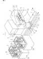
図13は本出願人が従来使用している取扱装置1について示すものである。この装置ではカセット3を設置するための複数のステージ24と、各種処理を行う処理装置6と、カセット3と前記処理装置6との間で薄板状物2を搬送する公知の産業用の搬送ロボット4と、この搬送ロボット4を処理装置6やカセット3の搬出入口25の正面へと移動を行う直線移動手段5を備えており、これらを用いて加工処理の施される薄板状物2は、カセット3の棚段26上から取り出されて、処理装置6の載置台23まで移動し、且つ載置される。
この後、処理装置6内で薄板状物2に対し各種の加工処理が施される。この際に薄板状物2を載置する位置精度について高い精度を必要とする加工処理がある。たとえば、2枚の薄板状物2の貼り合わせる処理を行う場合であり、このさい処理装置の所定載置位置に対して1枚目の薄板状物2と、2枚目の薄板状物2とを予め教示した位置へ、それぞれの傾きや位置のずれを生じさせることなく受け渡す必要がある。
ところで、前記したカセット3の棚段26上の薄板状物2は、左右方向にある程度の余裕を持って載置されており、この点でそれぞれは適宜に微妙なずれた状態で収納されている。したがって、このずれた状態のまま、薄板状物2を処理装置6へ搬送すれば正確な載置が行われず、処理製品の良品率(歩留まり)が悪くなる問題となる。
この問題を解決するための従来の手法は、上記位置ずれ状態を検出するための検出手段を処置装置付近に別途備えしめ、これを用いて薄板状物の位置ずれを検知すると共にずれ量を算出して、これを修正するようになすのであり、これら一連の手順を、図13に基づいて以下に説明する。
本実施例では検出手段18は直線移動手段5上へ設置されている。
始めに搬送ロボット4を直線移動手段5の作動でステージ24上に載置されたカセット3正面へ移動させ、次に、このロボットのアームを作動させてカセット3内部から薄板状物2をエンドエフェクタ11上に取り出す。その後、再び直線移動手段5の作動で搬送ロボット4を検出手段18の正面位置へ移動させると共に、エンドエフェクタ11上に載置されている薄板状物2の端縁が検出手段18の光軸を遮断するようにアーム12,13を回動させるのである。そして該回動で薄板状物2の縁部が検出手段18の光軸を遮断して得られる位置情報と、教示により予め得られている位置情報とを比較することで変位量を算出するのである。而して、この算出値に基づいて、搬送ロボット4は処理装置6の搬出入口25正面へと移動し、且つ支持アーム14の作動でエンドエフェクタ11の薄板状物2を載置台23上に載置するさい、上記算出値に基づいて修正した位置に載置するようになすのである。以上により、薄板状物2はその適正位置で必要な処理が行われるのであり、この後は再び搬送ロボット4によって処理装置6からカセット3へと返却(再収納)されるのである。
上記における検出手段18は、図示例の通り搬送ロボット4の移動途中に設けて上述の通り使用してもよいが、複数の処理装置の前面側へそれぞれ備えさせることができる。ここに検知手段18は投光器19と受光器20とからなる光学式の透過型センサであり、光軸は鉛直となして装置中央に一つ備えた構成である。
なお、予め教示により得られる位置情報とは、搬送ロボット4のエンドエフェクタ11上の薄板状物2が適正な所定位置にあるとき、該薄板状物2の縁部が検出手段18の光軸を遮断したときの位置情報のことである。
また、上記装置における搬送ロボット4はクリーンルーム用スカラ型の搬送ロボット4であって、薄板状物2を吸着保持するエンドエフェクタ11と、エンドエフェクタ11を回動可能に支持する支持アーム14(図示例では下アーム13と上アーム12の2体からなる)を回動させることができる旋回部15と、旋回部15を高さ方向に移動可能にする昇降手段16と、基台17とからなる。
図13に示す取扱装置1では、カセット3から処理装置6へ薄板状物2を運搬する途中にある検出手段18の箇所で搬送ロボット4を検知のために停止させる必要があり、上記カセットからの取り出し及び再収納の1サイクルに要する搬送時間が増大するため、生産効率が悪くなっている。
また、検出手段18を搬送ロボット4の直線移動手段5上に備えており、搬送ロボット4の移動中にその支持アームなどとの干渉を防止するため、投光器19と受光器20の距離を長くしたりする必要があるが、このように光軸を長くした検出手段18は非常に高価であり、且つ光軸調整が非常に困難であるなどの問題がある。もし調整の不十分な検出手段18で測定したとすれば、測定精度が低下して不具合が生じる問題となる。
日本特開平9−36201号公報で示される図2のものにおいては、各処理装置の薄板状物6の載置台18毎に多数の検出手段31を備える装置を提案している。この装置では薄板状物6の変位量を検出するため、載置台18の数だけ検出手段が必要であり、従ってコストが高くなるほか、検出手段31毎の調整が必要となって作業効率の低下につながるものとなる。
日本特開平9−162257号公報で示される図7のものにおいては、検出手段14を搬送ロボットのエフェクタ31cに備える装置を提案している。この搬送ロボットでは、検出手段14を回動するモータ等の動力源を別に備える必要があるため、この別途費用が掛かるほか、機構が複雑でかつ動作制御も困難になる問題がある。In general, a thin plate-like material such as a semiconductor or a liquid crystal substrate is manufactured in a highly clean environment, that is, a so-called clean room. The thin plate-like object is transported in the clean room by storing the thin plate-like object on a shelf in the cassette and transporting the cassette together with a large cassette transport robot or the like.
FIG. 13 shows the
Thereafter, various processings are performed on the thin plate-
By the way, the thin plate-
In the conventional method for solving this problem, a detection means for detecting the above-described misalignment state is separately provided in the vicinity of the treatment device, and this is used to detect the misalignment of the thin plate and calculate the misalignment amount. This is corrected, and a series of these procedures will be described below with reference to FIG.
In this embodiment, the detecting means 18 is installed on the linear moving means 5.
First, the
Although the detection means 18 in the above may be provided in the middle of the movement of the
The position information obtained by teaching in advance means that when the thin plate-
Further, the
In the
Further, the detection means 18 is provided on the linear movement means 5 of the
In FIG. 2 shown in Japanese Patent Laid-Open No. 9-36201, an apparatus including a large number of detection means 31 for each mounting table 18 of the thin plate-
In FIG. 7 shown in Japanese Patent Laid-Open No. 9-162257, a device is proposed that includes the detection means 14 in the effector 31c of the transport robot. In this transport robot, since it is necessary to separately provide a power source such as a motor for rotating the detecting means 14, there is a problem that this additional cost is required and the mechanism is complicated and the operation control becomes difficult.
本発明は本出願人が使用している取扱装置を改良したものであって、その特徴は取扱装置の位置を含めた基準座標系のもとで、エンドエフェクタ上に取り出した薄板状物の変位量を検出するさい、エンドエフェクタの支持アーム上に検出手段を取り付け、支持アームの回動動作時にエンドエフェクタ上の薄板状物の縁部と検出手段の光軸が交差するものとなし、これにより得られる数値と予め教示されてなる薄板状物の当該数値とを比較して修正変位量を算出するものとなすことを特徴とする。
また本発明では、上記の修正変位量の検出を、薄板状物がカセットの棚段から取り出される支持アームの動作中に行われる事を特徴とする。
また本発明では、支持アーム上に取り付ける変位量検出手段をコ字状体に形成し、且つその開放口をエンドエフェクタ側となるようにしてエンドエフェクタの手前側支持アーム上に配置するほか、その開放口を薄板状物の縁部が通過可能となる間隙寸法を有するものとなすのである。
また本発明では、コ字状体となした変位量検出手段の開放口側に取り付ける投光器と受光器からなる透過型センサの数及びその配置に関するもので、すなわち複数個の配置では支持アームの回動中心からの距離が異なる関係にずらして取り付けるようになすのであり、これにより支持アームの回動で薄板状物の縁部の複数箇所が同時に検出されるものとなる。
また本発明では、支持アームの回動動作中に支持アームに取り付けたコ字形状の検出手段により自動的に算出された修正変位量を基に、取扱装置を基準座標で所定の位置に修正して移動させ、薄板状物を載置台上の適正位置へ載置させるようになすのである。
すなわち、本発明の取扱装置1は、薄板状物2をカセットから取り出して移動するさい、エンドエフェクタ上の載置ずれを自動的に算出し、且つこれを修正して、処理装置の適正位置へ載置可能とする装置であり、その具体的構成は、薄板状物2を把持もしくは吸着して搬送する公知のロボット、および該搬送ロボット4を薄板状物2のカセット3が延在する方向に移動可能とするボールネジ軸等を備えた直線移動手段5、並びに搬送ロボット4によって薄板状物2を載置する載置台23を備え、且つこの載置台を水平面内で直線移動もしくは回動することで薄板状物の位置決めを行うアライメント装置等からなっている。
一方、取扱装置の位置を含めた基準座標系とは、取扱装置1が制御手段7からの動作命令により動作を行うときの取扱装置1の始動位置や、取扱装置1が配設される位置及び、受け渡し位置等を含んだ空間を仮想の座標としてみたてたものである。
他方、本発明の検出手段18はたとえば、光学式の透過型及び反射型のセンサ等であり、非接触で薄板状物2の縁部を検出するセンサが好ましい。この検出手段18は投光器19と受光器20からなり、投光器19と受光器20をコ字形の固定部材21の先端付近に向かい合わせて、光軸が鉛直となるよう又は傾斜状に備えており、薄板状物の縁部が光軸を遮断する事でその位置を検出するのである。The present invention is an improvement of the handling device used by the present applicant, and its feature is the displacement of the thin plate-like object taken out on the end effector under a reference coordinate system including the position of the handling device. When detecting the amount, the detection means is mounted on the support arm of the end effector, and the edge of the thin plate on the end effector and the optical axis of the detection means intersect when the support arm is rotated. The correction displacement amount is calculated by comparing the obtained numerical value with the numerical value of the thin plate-like object previously taught.
In the present invention, the correction displacement amount is detected during the operation of the support arm in which the thin plate-like object is taken out from the cassette shelf.
In the present invention, the displacement amount detecting means to be mounted on the support arm is formed in a U-shaped body, and the opening is located on the front support arm of the end effector so that the opening is on the end effector side. The opening has a gap dimension that allows the edge of the thin plate to pass through.
The present invention also relates to the number and arrangement of transmissive sensors composed of a projector and a light receiver attached to the opening side of the displacement detecting means formed into a U-shaped body. The distance from the center of movement is shifted and attached in different relations, so that a plurality of locations on the edge of the thin plate-like object are detected simultaneously by the rotation of the support arm.
In the present invention, the handling device is corrected to a predetermined position with reference coordinates based on the corrected displacement automatically calculated by the U-shaped detecting means attached to the support arm during the rotation of the support arm. The thin plate-like object is placed at an appropriate position on the placing table.
That is, the
On the other hand, the reference coordinate system including the position of the handling device refers to the starting position of the
On the other hand, the detection means 18 of the present invention is, for example, an optical transmission type or reflection type sensor, and a sensor that detects the edge of the thin plate-
図1は、本発明の搬送ロボット4の一実施例を示す斜視図面である。
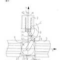
図2は、搬送ロボット4上に備えられた検知手段18を示す一部切り欠き斜視図である。
図3は、(a)〜(c)は搬送ロボット4が1個のセンサで検出量を算出する状態の使用説明図である。
図4は、上記で2個のセンサを使用した場合の作用説明図である。
図5は、薄板状物2の傾き状態を算出するための作用説明図である。
図6は、修正作用を説明する平面図である。
図7は、傾いた薄板状物2の修正作用を説明する平面図である。
図8は、検出手段を下アーム13に備える搬送ロボット4を示す平面図である。
図9は、(a)〜(c)は、上記に於ける薄板状物の変位量算出を示す説明図である。
図10は、搬送ロボット4の他の例を示す斜視図である。
図11は、搬送ロボット4の他の例を示す斜視図である。
図12は、搬送ロボット4の他の例を示す斜視図である。
図13は、従来の薄板状物の位置検出手段を備えた取扱装置の全体斜視図である。FIG. 1 is a perspective view showing an embodiment of the
FIG. 2 is a partially cutaway perspective view showing the detection means 18 provided on the
FIGS. 3A to 3C are explanatory diagrams of use in a state where the
FIG. 4 is an operation explanatory diagram when two sensors are used as described above.
FIG. 5 is an operation explanatory diagram for calculating the inclination state of the thin plate-
FIG. 6 is a plan view for explaining the correcting action.
FIG. 7 is a plan view for explaining the correcting action of the inclined thin plate-
FIG. 8 is a plan view showing the
FIGS. 9A to 9C are explanatory views showing the displacement amount calculation of the thin plate-like object in the above.
FIG. 10 is a perspective view showing another example of the
FIG. 11 is a perspective view showing another example of the
FIG. 12 is a perspective view showing another example of the
FIG. 13 is an overall perspective view of a handling apparatus provided with a conventional thin plate-like object position detecting means.
図1は図13で説明した本出願人の従来例を改良した取扱装置1であり、本発明の改良点は、処理装置6の前面や直線移動手段5上に備えしめたりする検出手段18を取り除き、即ちこれは独特なコ字形状となして支持アーム14上に備えさせるものとする。
以下に本発明の最良の実施形態の例を説明する。なお、以下の実施形態は本願発明の範囲を限定するものではない。したがって、当業者であれば本願発明の原理の範囲で、他の実施形態を採用することが可能である。
図2は本発明の検出手段18の部分拡大斜視図である。この検出手段18は扁平な開放口と奥行きを備えたコ字形状の固定部材21の先端付近に投光器19と受光器20を備えたものとなすのであり、かつその取り付けにはコ字形状の開放口がエンドエフェクタ11側を向けて設置されるようになされるのである。このさい投光器19と受光器20はそれぞれ1個設けるようになしてもよいが、複数個を図2に示すように奥側に向け位置をずらして設けるようにすることができる。
本発明では支持アーム14の回動動作と共に検出手段18が回動する際に、エンドエフェクタ11に保持された薄板状物2の縁部がコ字形状の固定部材21の開放口を通過し、投光器19から受光器19へ向かう光軸を遮断するのであり、これにより薄板状物2の位置検出が行われるのである。このため、コ字形状の開放口間隙P及びその奥行きSの寸法は薄板状物2の縁部が支障なく通過可能となる範囲で設計される。
而して、上記薄板状物2のエンドエフェクタ11上における位置ずれや傾きなどの算出は、支持アーム14の回動をX,Yの座標系で表示することにより算出するのであり、具体的にはエンドエフェクタ11を支持する支持アーム14の枢軸をX,Y座標の原点Oとし、X軸は搬送ロボット4が直線移動手段5を移動する方向であり、これに対しY軸はこれと直交する方向である。以下、その算出手法について説明する。
図3(a)〜(c)では、上アーム12に検出手段18を備えており、エンドエフェクタ11上の薄板状物2の点線は適正状態に置かれたものを、これ対し実線はずれた状態のものを示す。まず適正位置(教示位置)におけるデータを得るためには次のようにして行われる。支持アーム14が回動し、上アーム12上のセンサ31が図3(a)のAから図3(c)の薄板状物2の縁部を検出する位置Bまで回動することで、その回動角度(測定値)を得ることがきるのであり、具体的には、始点Aの座標を(XA,YA)となし、教示位置Bの座標を(XB,YB)として回動角度を測定し、この測定した回動角度を基に教示位置を算出するのである。
上述の教示位置の座標を算出する式は次の通りとなる。
次に、実線で示される薄板状物2とのずれについては、支持アームがさらに回動した即ち図3(c)における座標(XC,YC)を測定するのであり、この変位位置の座標を算出する式は次の通りである。
ところで、X軸方向の変位量LCを算出するには、上記教示位置と変位位置とのX座標値の差を求めるのであり、式は次のとおりである。
本発明ではコ字形状の検知手段18に対し、2個以上のセンサを備えることができるのであり、次に2個のセンサを取り付けた例について図4により説明する。2個のセンサは適当な間隔をあけて設けるのであり、これによりそれぞれの回動半径を異ならしめるのであり、支持アーム14の回動で薄板状物2の縁部における2箇所の位置検出が効率よく行われるものとなる。また、このものでは検出した測定値を基に薄板状物2のX軸方向の変位量と薄板状物の傾き40を算出することができる。
図4(a)〜(c)は図3と同様にして、その算出手段を図解して示すものである。図面で32,33は2個のセンサを示しており、エンドエェクタ11上の点線で示した薄板状物2は教示位置を、これに対し実線はずれた状態のものを示す。図中(b)は支持アーム14の回動で教示位置を算出する状態を、同(c)はずれた位置を算出する状態の説明図である。
まず、教示位置の算出は次の式により求めることができる。
これに対し変位位置F(XF,YF),I(XI,YI)は次の式で算出することができる。
次に、図5にもとづいて薄板状物の傾き40の算出方法を説明する。
本発明で薄板状物の傾き40は、エンドエフェクタ11上で薄板状物が部分的な回動を生じさせられたものであって、これは教示位置の規準となされる薄板状物2の中心線41(Y軸と平行)と変位した薄板状物2の中心線43とが角度θLだけ傾きを生じるときその角度θLとして表される。ところで、実施例の薄板状物2は長方形の平面形状をなしており、薄板状物2の中心線43とその縁部側面は平行である。このもので薄板状物の傾きの角度θLを数値的に算出するには、変位した薄板状物2の2つの検出位置FからIへ向かうベクトルFIと、教示した薄板状物の中心線41上の単位ベクトルyとがなす角度θLを算出することで求めることができる。
ベクトルFIは、
Y軸上の単位ベクトルyは、
従って、ベクトルFIとベクトルYとがなす角度θLは、次のように表すことができる。
[載置位置の修正方法]
本発明では変位している薄板状物2を修正して載置するために、先に得た変位量及び傾きを基にして薄板状物2の位置修正を行うのであり、この修正の仕方を図6に基づいて説明する。
図面で4は搬送ロボット、5はその直線移動手段であって、搬送ロボット4の旋回部15の回転中心を原点Oとする座標として考える。而して、この座標では、直線移動手段5の移動方向をX軸となし、Y軸は原点OでX軸と直交する方向であり、且つこれは薄板状物を教示位置へ載置させる方向である。
本図で薄板状物2のX軸方向の変位量LCを修正するには、前述の式(24)で求めた算出値により行うのである。これは実線で示す変位位置にある薄板状物2を、点線で示す教示位置に修正するのであり、搬送ロボット4を直線移動手段に対してX軸の正方向へ距離LC=XA(cosθB−cosθC)−YA(sinθB−sinθC)だけ移動することで可能となる。
図7は傾いた薄板状物2の修正の方法を示すものであり、本図では、上アーム12に2個のセンサ32、33を備えたものとなしてある以外は図6と変わりない。
実線の傾いた薄板状物2を点線の適正位置(教示位置)に修正するには、搬送ロボット4の旋回部15を用いて反時計回りに角度θL=YFI/(XFI2+XFI2)1/2だけ回動する。この回動によって薄板状物2の縁部上の点Fは点Jへと移転し、点Fと点JとのX軸方向の変位量LJが生じる。これを修正するため、直線移動手段5で搬送ロボット4を変位量である距離LJだけ移動する。
上述のX軸方向における移動量である距離LJの算出方法は次の通りである。
次に、教示位置Eと上述の算出値Jとを比較してX軸方向の変位量Lを次式で算出する。
上記の実施例では検出手段18を上アーム12に備える実施例を説明したが、図8に示す搬送ロボット4では、検出手段18を下アーム13に備える。この搬送ロボット4では、回動時に検出手段18と上アーム12との衝突をさけるため、下アーム13と上アーム12とを連結する支軸29が従来のものより長くなっており、高さ方向に距離Tだけ間隙を設けている。
また、この実施例のエンドエフェクタ11は下アーム13の下部に備えしめてある。
図9(a)〜(c)は、図8の搬送ロボット4で薄板状物2を取り出す(受け渡す)際に、起生するエンドエフェクタ11上のずれ(変位量)を算出する手法を図解して示すものである。図面で31は検出手段18のセンサを示しており、エンドエェクタ11上の点線で示した薄板状物2は教示位置を、これに対し実線は距離LNだけずれた状態のものを示す。
本例では旋回部15の回動中心を座標の原点Oとして下アーム13上に設けた検出手段18のセンサ31が回動する。このとき得られる測定値を基に上述の計算式を利用して同様に変位量を算出することができる。
図9(a)では、センサ31が上記動作始点K(XK,YK)にある状態を示している。
図9(b)では、センサ31が動作始点K(XK,YK)から角度θMだけ回動して、教示位置M(XM,YM)にある状態を示している。
図9(c)では、センサ31をさらに動作始点からの角度θNまで回動して、検知位置N(XN,YN)にある状態を示している。
この搬送ロボット4を用いて薄板状物2の変位量を算出する手順は、上述の検出手段18が上アーム12に備える場合と同様であり、その結果、次式の通り変位量LNが得られる。
また、本図の搬送ロボット4は旋回部15と下アーム13とが一体化しており、下アーム13を動作させる代わりに旋回部15を回動することで、図1の搬送ロボット4と同様の動作が可能となり、同様の算出手法を用いて変位量を算出することができる。
本例では旋回部15と一体化されて回動する2組の下アーム13,13上に取り付ける1組の上アーム12については、回動中の緩衝を避けるために従来のものより少し長い支軸29を備えることで高さ方向に隙間(距離T)が形成されるものとなしてある。而して、検出手段18を他のものでは上アーム12の上部に設けるものとなすが、前記の隙間を形成した上アーム12ではその下部に備えしめるのである。
図10では下アーム13と旋回部15とが一体化した搬送ロボット4について説明したが図1に示す搬送ロボット4のように下アーム13と旋回部15とが独立して動作でき、支持アーム14を2組備える搬送ロボット4であっても本発明を実施することが可能である。
上述した搬送ロボット4では支持アーム14の構成を上アーム12と下アーム13の2個になしたが、図10の搬送ロボット4は、支持アーム14を上アーム13だけの1個となしたものであり、検知手段18はアーム12に於けるエンドエフェクタ11と反対側の側面に取り付けたものとなしてある。
また、図12の搬送ロボット4の支持アーム14は上記例と異なる3個、即ち上アーム12と、中間アーム28と、下アーム13とで構成される。この搬送ロボット4では検出手段18を上アーム12に備えるものとなしたが、中間アーム29若しくは下アーム13に備えるようになしても良く、本発明の実施の範囲とする。
本発明では、検出手段18を搬送ロボットの支持アーム14に対し独特の構成で取り付けしめることで、搬送ロボット4が薄板状物2を取り出す(受け渡す)動作中、自動的且つ迅速にその変位量検出を行うことができるのであり、装置全体のコスト低減下と生産性の向上に寄与すること大ならしめるものである。
なお、コ字状となした検出手段18は投光・受光間の光軸が短いので、このセンサの調整やメンテナンスが極めて容易であり、価格も安価なものである。FIG. 1 shows a
Examples of the best mode of the present invention will be described below. The following embodiments do not limit the scope of the present invention. Accordingly, those skilled in the art can employ other embodiments within the scope of the principle of the present invention.
FIG. 2 is a partially enlarged perspective view of the detecting means 18 of the present invention. The detecting means 18 is provided with a
In the present invention, when the detection means 18 rotates together with the rotation operation of the
Thus, the positional deviation and inclination of the thin plate-
3 (a) to 3 (c), the
The formula for calculating the coordinates of the teaching position is as follows.
Next, regarding the deviation from the thin plate-
Incidentally, the calculated displacement amount LC of the X-axis direction is of obtaining a difference between the X coordinate value of the displacement position and the teaching position, the formula is as follows.
In the present invention, two or more sensors can be provided for the U-shaped detection means 18, and an example in which two sensors are attached will be described with reference to FIG. The two sensors are provided at an appropriate interval, whereby the respective turning radii are made different, and the position detection at two positions on the edge of the thin plate-
4 (a) to 4 (c) illustrate the calculation means in the same manner as FIG. In the drawing,
First, the teaching position can be calculated by the following equation.
On the other hand, the displacement positions F (XF , YF ), I (XI , YI ) can be calculated by the following equations.
Next, a method of calculating the
In the present invention, the
The vector FI is
The unit vector y on the Y axis is
Therefore, the angle θL formed by the vector FI and the vector Y can be expressed as follows.
[How to correct the mounting position]
In the present invention, in order to correct and place the displaced thin plate-
In the drawing,
To correct the displacement amount LC of the X-axis direction of the thin plate-
FIG. 7 shows a method of correcting the tilted thin plate-
In order to correct the thin plate-
The method of calculating the distance LJ is a shift amount in the X-axis direction described above is as follows.
Next, the teaching position E is compared with the above-described calculated value J to calculate the displacement amount L in the X-axis direction by the following equation.
In the above-described embodiment, the embodiment in which the
Further, the
9A to 9C illustrate a method of calculating a deviation (displacement amount) on the
In this example, the
FIG. 9A shows a state in which the
FIG. 9B shows a state in which the
FIG. 9C shows a state in which the
The procedure for calculating the amount of displacement of the thin plate-
Further, in the
In this example, the pair of
Although the
In the
Further, the
In the present invention, the detection means 18 is attached to the
Note that the U-shaped detection means 18 has a short optical axis between light projection and light reception, so that adjustment and maintenance of the sensor are extremely easy and the price is low.
【0005】
その特徴は取扱装置の位置を含めた基準座標系のもとで、エンドエフェクタ上に取り出した薄板状物の変位量を検出するさい、エンドエフェクタの支持アーム上の板材面内へコ字状体に形成した検出手段を取り付け、支持アームの回動動作時にエンドエフェクタ上の薄板状物の縁部と検出手段の光軸がコ字状体の開放口内で交差するものとなし、これにより得られる数値と予め教示されてなる薄板状物の当該数値とを比較して修正変位量を算出するものとなすことを特徴とする。
また本発明では、上記の修正変位量の検出を、薄板状物がカセットの棚段から取り出される支持アームの動作中に行われる事を特徴とする。
また本発明の変位量検出手段は透過型センサの検出手段であって、上記コ字状体の開放口をエンドエフェクタ側となるようにしてエンドエフェクタの手前側支持アーム上に配置するほか、その開放口を薄板状物の縁部が通過可能となる間隙寸法を有するものとなすのである。
また本発明では、コ字状体となした変位量検出手段の開放口側に取り付ける投光器と受光器からなる透過型センサの数及びその配置に関するもので、すなわち複数個の配置では支持アームの回動中心からの距離が異なる関係にずらして取り付けるようになすのであり、これにより支持アームの回動で薄板状物の縁部の複数箇所が同時に検出されるものとなる。
また本発明では、支持アームの回動動作中に支持アームに取り付けたコ字形状の検出手段により自動的に算出された修正変位量を基に、取扱装置を基準座標で所定の位置に修正して移動させ、薄板状物を載置台上の適正位置へ載置させるようになすのである。[0005]
Its feature is that it is U-shaped in the plane of the plate on the support arm of the end effector when detecting the amount of displacement of the thin plate taken out on the end effector under the reference coordinate system including the position of the handling device. The detecting means formed in the above is attached, and the edge of the thin plate-like object on the end effector and the optical axis of the detecting means intersect in the opening of the U-shaped body when the support arm rotates, and this is obtained. The correction displacement amount is calculated by comparing the numerical value and the numerical value of the thin plate-like object previously taught.
In the present invention, the correction displacement amount is detected during the operation of the support arm in which the thin plate-like object is taken out from the cassette shelf.
The displacement amount detecting means of the present invention is a detecting means of a transmissive sensor, and is disposed on the front support arm of the end effector so that the opening of the U-shaped body is on the end effector side. The opening has a gap dimension that allows the edge of the thin plate to pass through.
The present invention also relates to the number and arrangement of transmissive sensors composed of a projector and a light receiver attached to the opening side of the displacement detecting means formed into a U-shaped body. The distance from the center of movement is shifted and attached in different relations, so that a plurality of locations on the edge of the thin plate-like object are detected simultaneously by the rotation of the support arm.
In the present invention, the handling device is corrected to a predetermined position with reference coordinates based on the corrected displacement automatically calculated by the U-shaped detecting means attached to the support arm during the rotation of the support arm. The thin plate-like object is placed at an appropriate position on the placing table.
【0007】
図3は、(a)〜(c)は搬送ロボット4が1個のセンサで検出量を算出する状態の使用説明図である。
図4は、上記で2個のセンサを使用した場合の作用説明図である。
図5は、薄板状物2の傾き状態を算出するための作用説明図である。
図6は、修正作用を説明する平面図である。
図7は、傾いた薄板状物2の修正作用を説明する平面図である。
図8は、検出手段を下アーム13に備える搬送ロボット4を示す平面図である。
図9は、(a)〜(c)は、上記に於ける薄板状物の変位量算出を示す説明図である。
図10は、搬送ロボット4の他の例を示す斜視図である。
図11は、搬送ロボット4の他の例を示す斜視図である。
図12は、搬送ロボット4の他の例を示す斜視図である。
図13は、従来の薄板状物の位置検出手段を備えた取扱装置の全体斜視図である。
[発明を実施するための最良の形態]
図1は図13で説明した本出願人の従来例を改良した取扱装置1であり、本発明の改良点は、処理装置6の前面や直線移動手段5上に備えしめたりする検出手段18を取り除き、即ちこれは独特なコ字形状となして支持アーム14の板材面内に備えさせるものとする。
以下に本発明の最良の実施形態の例を説明する。なお、以下の実施形態は本願発明の範囲を限定するものではない。したがって、当業者であれば本願発明の原理の範囲で、他の実施形態を採用することが可能である。[0007]
FIGS. 3A to 3C are explanatory diagrams of use in a state where the
FIG. 4 is an operation explanatory diagram when two sensors are used as described above.
FIG. 5 is an operation explanatory diagram for calculating the inclination state of the thin plate-
FIG. 6 is a plan view for explaining the correcting action.
FIG. 7 is a plan view for explaining the correcting action of the inclined thin plate-
FIG. 8 is a plan view showing the
FIGS. 9A to 9C are explanatory views showing the displacement amount calculation of the thin plate-like object in the above.
FIG. 10 is a perspective view showing another example of the
FIG. 11 is a perspective view showing another example of the
FIG. 12 is a perspective view showing another example of the
FIG. 13 is an overall perspective view of a handling apparatus provided with a conventional thin plate-like object position detecting means.
[Best Mode for Carrying Out the Invention]
FIG. 1 shows a
Examples of the best mode of the present invention will be described below. The following embodiments do not limit the scope of the present invention. Accordingly, those skilled in the art can employ other embodiments within the scope of the principle of the present invention.
Claims (5)
Translated fromJapaneseApplications Claiming Priority (1)
| Application Number | Priority Date | Filing Date | Title |
|---|---|---|---|
| PCT/JP2003/008629WO2005004227A1 (en) | 2003-07-07 | 2003-07-07 | Thin sheet-like article displacement detection method and displacement correction method |
Publications (2)
| Publication Number | Publication Date |
|---|---|
| JPWO2005004227A1true JPWO2005004227A1 (en) | 2006-09-28 |
| JP4395873B2 JP4395873B2 (en) | 2010-01-13 |
Family
ID=33562099
Family Applications (1)
| Application Number | Title | Priority Date | Filing Date |
|---|---|---|---|
| JP2005503395AExpired - LifetimeJP4395873B2 (en) | 2003-07-07 | 2003-07-07 | Displacement amount detection method and displacement amount correction method for thin plate-like object |
Country Status (6)
| Country | Link |
|---|---|
| JP (1) | JP4395873B2 (en) |
| KR (1) | KR100981078B1 (en) |
| CN (1) | CN1802736B (en) |
| AU (1) | AU2003304309A1 (en) |
| TW (1) | TWI230782B (en) |
| WO (1) | WO2005004227A1 (en) |
Families Citing this family (15)
| Publication number | Priority date | Publication date | Assignee | Title |
|---|---|---|---|---|
| US7946800B2 (en) | 2007-04-06 | 2011-05-24 | Brooks Automation, Inc. | Substrate transport apparatus with multiple independently movable articulated arms |
| US8267636B2 (en) | 2007-05-08 | 2012-09-18 | Brooks Automation, Inc. | Substrate transport apparatus |
| JP5146641B2 (en)* | 2007-06-06 | 2013-02-20 | 株式会社安川電機 | Substrate transfer robot and control method of substrate transfer robot |
| JP4697192B2 (en)* | 2007-06-12 | 2011-06-08 | 東京エレクトロン株式会社 | Position shift detection device and processing system using the same |
| US20100162955A1 (en)* | 2008-12-31 | 2010-07-01 | Lawrence Chung-Lai Lei | Systems and methods for substrate processing |
| JP2012210676A (en)* | 2011-03-31 | 2012-11-01 | Sinfonia Technology Co Ltd | Robot arm type transport apparatus |
| US8958907B2 (en)* | 2011-03-31 | 2015-02-17 | Sinfonia Technology Co., Ltd. | Robot arm apparatus |
| JP5532110B2 (en)* | 2012-11-16 | 2014-06-25 | 株式会社安川電機 | Substrate transfer robot and substrate transfer method |
| CN103972135B (en)* | 2013-01-25 | 2017-02-22 | 上海微电子装备有限公司 | Silicon wafer accurate positioning and conveying device and positioning method |
| JP2016143787A (en)* | 2015-02-03 | 2016-08-08 | 川崎重工業株式会社 | Substrate transfer robot and substrate transfer method |
| CN106956290B (en)* | 2017-04-17 | 2019-09-10 | 京东方科技集团股份有限公司 | Mechanical arm and its operating method, robot arm device and display panel production equipment |
| CN109877823A (en)* | 2017-12-06 | 2019-06-14 | 沈阳新松机器人自动化股份有限公司 | A kind of pair puts correction tow-armed robot and its method for correcting error |
| CN109877822A (en)* | 2017-12-06 | 2019-06-14 | 沈阳新松机器人自动化股份有限公司 | A kind of pair takes correction tow-armed robot and its method for correcting error |
| JP7443142B2 (en)* | 2020-04-10 | 2024-03-05 | ニデックインスツルメンツ株式会社 | Industrial robots and industrial robot control methods |
| JP2023053455A (en)* | 2021-10-01 | 2023-04-13 | 日本電産サンキョー株式会社 | INDUSTRIAL ROBOT AND CONTROL METHOD FOR INDUSTRIAL ROBOT |
Family Cites Families (5)
| Publication number | Priority date | Publication date | Assignee | Title |
|---|---|---|---|---|
| JPH07335723A (en)* | 1994-06-08 | 1995-12-22 | Nikon Corp | Positioning device |
| JPH11106044A (en)* | 1997-10-08 | 1999-04-20 | Mitsubishi Electric Corp | Substrate transfer device and substrate transfer method |
| JP2002093882A (en)* | 2000-09-20 | 2002-03-29 | Olympus Optical Co Ltd | Substrate-transferring device and substrate-inspecting system |
| TW550651B (en)* | 2001-08-08 | 2003-09-01 | Tokyo Electron Ltd | Substrate conveying apparatus, substrate processing system, and substrate conveying method |
| JP3960162B2 (en) | 2001-08-08 | 2007-08-15 | 東京エレクトロン株式会社 | Substrate transfer apparatus, substrate processing system, and substrate transfer method |
- 2003
- 2003-07-07KRKR1020067000394Apatent/KR100981078B1/ennot_activeExpired - Lifetime
- 2003-07-07TWTW092118459Apatent/TWI230782B/ennot_activeIP Right Cessation
- 2003-07-07AUAU2003304309Apatent/AU2003304309A1/ennot_activeAbandoned
- 2003-07-07JPJP2005503395Apatent/JP4395873B2/ennot_activeExpired - Lifetime
- 2003-07-07CNCN03826756.XApatent/CN1802736B/ennot_activeExpired - Lifetime
- 2003-07-07WOPCT/JP2003/008629patent/WO2005004227A1/enactiveApplication Filing
Also Published As
| Publication number | Publication date |
|---|---|
| WO2005004227A1 (en) | 2005-01-13 |
| JP4395873B2 (en) | 2010-01-13 |
| KR100981078B1 (en) | 2010-09-08 |
| KR20060065627A (en) | 2006-06-14 |
| CN1802736B (en) | 2013-01-09 |
| TWI230782B (en) | 2005-04-11 |
| CN1802736A (en) | 2006-07-12 |
| AU2003304309A1 (en) | 2005-01-21 |
| TW200502531A (en) | 2005-01-16 |
Similar Documents
| Publication | Publication Date | Title |
|---|---|---|
| JP4395873B2 (en) | Displacement amount detection method and displacement amount correction method for thin plate-like object | |
| KR101817395B1 (en) | Method and apparatus for detecting position of substrate transfer device, and storage medium | |
| JP4260423B2 (en) | Disc-shaped object reference position teaching method, positioning method, and transport method, and disc-shaped reference position teaching apparatus, positioning apparatus, transport apparatus, and semiconductor manufacturing equipment using these methods | |
| US10468284B2 (en) | Substrate processing apparatus and substrate processing method | |
| JP4454211B2 (en) | Substrate transfer robot system and substrate transfer container used in this substrate transfer robot system | |
| JP2000127069A5 (en) | Transport alignment method and transport system for transport system | |
| JP6468159B2 (en) | Transport system and transport method | |
| JP2003117862A (en) | Method and device for adjusting position of hand | |
| JP2015032617A (en) | Teaching data correction method of carrier robot, and carrier system | |
| TW200807610A (en) | Conveying device and method | |
| US11335578B2 (en) | Substrate transfer apparatus and method of measuring positional deviation of substrate | |
| JP2006351884A (en) | Substrate transport mechanism and processing system | |
| JP2002118162A (en) | Method for transfer alignment in object processing system and object processing system | |
| US7596425B2 (en) | Substrate detecting apparatus and method, substrate transporting apparatus and method, and substrate processing apparatus and method | |
| US12002695B2 (en) | Transport system and determination method | |
| JP2005193303A (en) | Substrate transporting device | |
| JP4607994B2 (en) | Disk-shaped object positioning method, disk-shaped object positioning device using the method, transfer device, and semiconductor manufacturing equipment | |
| US20240058952A1 (en) | Controller for substrate transfer robot and control method for joint motor | |
| JP6281554B2 (en) | Teaching jig, robot, teaching system and teaching method | |
| JP2007088110A (en) | Method of teaching reference position of substrate transfer robot | |
| JP2006269497A (en) | Substrate-treating device and substrate storage method | |
| CN119096344A (en) | Control device of substrate conveying robot and control method of substrate conveying robot | |
| JP4580719B2 (en) | Substrate transport apparatus and substrate transport method | |
| JPH0656228A (en) | Reference position automatic teaching method for conveyng robot | |
| JP2007189072A (en) | Tray transport system |
Legal Events
| Date | Code | Title | Description |
|---|---|---|---|
| A521 | Request for written amendment filed | Free format text:JAPANESE INTERMEDIATE CODE: A821 Effective date:20070612 | |
| RD02 | Notification of acceptance of power of attorney | Free format text:JAPANESE INTERMEDIATE CODE: A7422 Effective date:20070612 | |
| A131 | Notification of reasons for refusal | Free format text:JAPANESE INTERMEDIATE CODE: A131 Effective date:20090127 | |
| A521 | Request for written amendment filed | Free format text:JAPANESE INTERMEDIATE CODE: A523 Effective date:20090327 | |
| A131 | Notification of reasons for refusal | Free format text:JAPANESE INTERMEDIATE CODE: A131 Effective date:20090512 | |
| A521 | Request for written amendment filed | Free format text:JAPANESE INTERMEDIATE CODE: A523 Effective date:20090703 | |
| A131 | Notification of reasons for refusal | Free format text:JAPANESE INTERMEDIATE CODE: A131 Effective date:20090804 | |
| A521 | Request for written amendment filed | Free format text:JAPANESE INTERMEDIATE CODE: A523 Effective date:20090807 | |
| TRDD | Decision of grant or rejection written | ||
| A01 | Written decision to grant a patent or to grant a registration (utility model) | Free format text:JAPANESE INTERMEDIATE CODE: A01 Effective date:20090929 | |
| A01 | Written decision to grant a patent or to grant a registration (utility model) | Free format text:JAPANESE INTERMEDIATE CODE: A01 | |
| A61 | First payment of annual fees (during grant procedure) | Free format text:JAPANESE INTERMEDIATE CODE: A61 Effective date:20091009 | |
| FPAY | Renewal fee payment (event date is renewal date of database) | Free format text:PAYMENT UNTIL: 20121030 Year of fee payment:3 | |
| R150 | Certificate of patent or registration of utility model | Ref document number:4395873 Country of ref document:JP Free format text:JAPANESE INTERMEDIATE CODE: R150 Free format text:JAPANESE INTERMEDIATE CODE: R150 | |
| FPAY | Renewal fee payment (event date is renewal date of database) | Free format text:PAYMENT UNTIL: 20131030 Year of fee payment:4 | |
| R250 | Receipt of annual fees | Free format text:JAPANESE INTERMEDIATE CODE: R250 | |
| R250 | Receipt of annual fees | Free format text:JAPANESE INTERMEDIATE CODE: R250 | |
| R250 | Receipt of annual fees | Free format text:JAPANESE INTERMEDIATE CODE: R250 | |
| R250 | Receipt of annual fees | Free format text:JAPANESE INTERMEDIATE CODE: R250 | |
| R250 | Receipt of annual fees | Free format text:JAPANESE INTERMEDIATE CODE: R250 | |
| R250 | Receipt of annual fees | Free format text:JAPANESE INTERMEDIATE CODE: R250 | |
| R250 | Receipt of annual fees | Free format text:JAPANESE INTERMEDIATE CODE: R250 | |
| R250 | Receipt of annual fees | Free format text:JAPANESE INTERMEDIATE CODE: R250 | |
| R250 | Receipt of annual fees | Free format text:JAPANESE INTERMEDIATE CODE: R250 | |
| R250 | Receipt of annual fees | Free format text:JAPANESE INTERMEDIATE CODE: R250 | |
| R250 | Receipt of annual fees | Free format text:JAPANESE INTERMEDIATE CODE: R250 | |
| EXPY | Cancellation because of completion of term |