JPWO2002049696A1 - Protector and indwelling needle assembly - Google Patents
Protector and indwelling needle assemblyDownload PDFInfo
- Publication number
- JPWO2002049696A1 JPWO2002049696A1JP2002551033AJP2002551033AJPWO2002049696A1JP WO2002049696 A1JPWO2002049696 A1JP WO2002049696A1JP 2002551033 AJP2002551033 AJP 2002551033AJP 2002551033 AJP2002551033 AJP 2002551033AJP WO2002049696 A1JPWO2002049696 A1JP WO2002049696A1
- Authority
- JP
- Japan
- Prior art keywords
- needle
- protector
- posture
- needle body
- tip
- Prior art date
- Legal status (The legal status is an assumption and is not a legal conclusion. Google has not performed a legal analysis and makes no representation as to the accuracy of the status listed.)
- Granted
Links
- 230000001012protectorEffects0.000titleclaimsabstractdescription359
- 230000033001locomotionEffects0.000claimsabstractdescription39
- 230000002093peripheral effectEffects0.000claimsabstractdescription19
- 239000000463materialSubstances0.000claimsdescription31
- 229920005989resinPolymers0.000claimsdescription23
- 239000011347resinSubstances0.000claimsdescription23
- 230000000149penetrating effectEffects0.000claimsdescription13
- 239000007769metal materialSubstances0.000claimsdescription11
- 230000033228biological regulationEffects0.000claimsdescription3
- 230000001105regulatory effectEffects0.000claimsdescription3
- 230000035515penetrationEffects0.000claimsdescription2
- -1polyethylenePolymers0.000description19
- 210000004204blood vesselAnatomy0.000description18
- 229920003023plasticPolymers0.000description18
- 239000004033plasticSubstances0.000description18
- 238000003825pressingMethods0.000description16
- 210000004369bloodAnatomy0.000description14
- 239000008280bloodSubstances0.000description14
- 238000006073displacement reactionMethods0.000description13
- 238000003860storageMethods0.000description13
- 238000002347injectionMethods0.000description11
- 239000007924injectionSubstances0.000description11
- 238000000034methodMethods0.000description9
- 239000000470constituentSubstances0.000description8
- 230000007423decreaseEffects0.000description7
- 230000000694effectsEffects0.000description7
- 238000012545processingMethods0.000description7
- RYGMFSIKBFXOCR-UHFFFAOYSA-NCopperChemical compound[Cu]RYGMFSIKBFXOCR-UHFFFAOYSA-N0.000description6
- XEEYBQQBJWHFJM-UHFFFAOYSA-NIronChemical compound[Fe]XEEYBQQBJWHFJM-UHFFFAOYSA-N0.000description6
- 239000010949copperSubstances0.000description6
- 229910052802copperInorganic materials0.000description6
- 239000012530fluidSubstances0.000description6
- 239000004698PolyethyleneSubstances0.000description5
- 239000004743PolypropyleneSubstances0.000description5
- 229920000728polyesterPolymers0.000description5
- 229920000573polyethylenePolymers0.000description5
- 229920001155polypropylenePolymers0.000description5
- 239000004814polyurethaneSubstances0.000description5
- 229920002635polyurethanePolymers0.000description5
- 230000002265preventionEffects0.000description5
- 229910000838Al alloyInorganic materials0.000description4
- 239000004793PolystyreneSubstances0.000description4
- RTAQQCXQSZGOHL-UHFFFAOYSA-NTitaniumChemical compound[Ti]RTAQQCXQSZGOHL-UHFFFAOYSA-N0.000description4
- 229920000122acrylonitrile butadiene styrenePolymers0.000description4
- 229910052782aluminiumInorganic materials0.000description4
- XAGFODPZIPBFFR-UHFFFAOYSA-NaluminiumChemical compound[Al]XAGFODPZIPBFFR-UHFFFAOYSA-N0.000description4
- 239000003814drugSubstances0.000description4
- 229940079593drugDrugs0.000description4
- 229910001000nickel titaniumInorganic materials0.000description4
- 239000004417polycarbonateSubstances0.000description4
- 229920000515polycarbonatePolymers0.000description4
- 229920006324polyoxymethylenePolymers0.000description4
- 229920002223polystyrenePolymers0.000description4
- 239000000243solutionSubstances0.000description4
- 229910001220stainless steelInorganic materials0.000description4
- 239000010935stainless steelSubstances0.000description4
- 239000010936titaniumSubstances0.000description4
- 229920000178Acrylic resinPolymers0.000description3
- 239000004925Acrylic resinSubstances0.000description3
- 229910000990Ni alloyInorganic materials0.000description3
- 239000004696Poly ether ether ketoneSubstances0.000description3
- 239000004952PolyamideSubstances0.000description3
- 239000005062PolybutadieneSubstances0.000description3
- 239000004734Polyphenylene sulfideSubstances0.000description3
- 229910045601alloyInorganic materials0.000description3
- 239000000956alloySubstances0.000description3
- 238000013459approachMethods0.000description3
- 238000005452bendingMethods0.000description3
- 210000001124body fluidAnatomy0.000description3
- 239000010839body fluidSubstances0.000description3
- 239000005038ethylene vinyl acetateSubstances0.000description3
- 230000004927fusionEffects0.000description3
- 238000001802infusionMethods0.000description3
- 229920000554ionomerPolymers0.000description3
- 229910052742ironInorganic materials0.000description3
- 229920001200poly(ethylene-vinyl acetate)Polymers0.000description3
- 229920003229poly(methyl methacrylate)Polymers0.000description3
- 229920002647polyamidePolymers0.000description3
- 229920002857polybutadienePolymers0.000description3
- 229920001707polybutylene terephthalatePolymers0.000description3
- 229920002530polyetherether ketonePolymers0.000description3
- 229920000139polyethylene terephthalatePolymers0.000description3
- 239000005020polyethylene terephthalateSubstances0.000description3
- 239000004926polymethyl methacrylateSubstances0.000description3
- 229920000098polyolefinPolymers0.000description3
- 229920000069polyphenylene sulfidePolymers0.000description3
- 239000004800polyvinyl chlorideSubstances0.000description3
- 229920000915polyvinyl chloridePolymers0.000description3
- 238000009423ventilationMethods0.000description3
- 229930182556PolyacetalNatural products0.000description2
- 229910001069Ti alloyInorganic materials0.000description2
- 239000000853adhesiveSubstances0.000description2
- 230000001070adhesive effectEffects0.000description2
- 238000011109contaminationMethods0.000description2
- 229920001971elastomerPolymers0.000description2
- 229920000840ethylene tetrafluoroethylene copolymerPolymers0.000description2
- 238000004519manufacturing processMethods0.000description2
- 239000005060rubberSubstances0.000description2
- 229920002725thermoplastic elastomerPolymers0.000description2
- 229910052719titaniumInorganic materials0.000description2
- 239000004677NylonSubstances0.000description1
- 239000004721Polyphenylene oxideSubstances0.000description1
- 241001422033ThestylusSpecies0.000description1
- 210000001367arteryAnatomy0.000description1
- 230000000903blocking effectEffects0.000description1
- 230000017531blood circulationEffects0.000description1
- 230000036772blood pressureEffects0.000description1
- 230000003247decreasing effectEffects0.000description1
- 238000010586diagramMethods0.000description1
- 238000005516engineering processMethods0.000description1
- 208000015181infectious diseaseDiseases0.000description1
- 230000009545invasionEffects0.000description1
- 239000007788liquidSubstances0.000description1
- 239000004745nonwoven fabricSubstances0.000description1
- 229920001778nylonPolymers0.000description1
- 239000005022packaging materialSubstances0.000description1
- 229920000570polyetherPolymers0.000description1
- 230000000717retained effectEffects0.000description1
- 238000000926separation methodMethods0.000description1
- 238000010561standard procedureMethods0.000description1
- 230000008961swellingEffects0.000description1
- 229920003002synthetic resinPolymers0.000description1
- 239000000057synthetic resinSubstances0.000description1
- 210000003462veinAnatomy0.000description1
Images


Classifications
- A—HUMAN NECESSITIES
- A61—MEDICAL OR VETERINARY SCIENCE; HYGIENE
- A61M—DEVICES FOR INTRODUCING MEDIA INTO, OR ONTO, THE BODY; DEVICES FOR TRANSDUCING BODY MEDIA OR FOR TAKING MEDIA FROM THE BODY; DEVICES FOR PRODUCING OR ENDING SLEEP OR STUPOR
- A61M5/00—Devices for bringing media into the body in a subcutaneous, intra-vascular or intramuscular way; Accessories therefor, e.g. filling or cleaning devices, arm-rests
- A61M5/14—Infusion devices, e.g. infusing by gravity; Blood infusion; Accessories therefor
- A61M5/158—Needles for infusions; Accessories therefor, e.g. for inserting infusion needles, or for holding them on the body
- A—HUMAN NECESSITIES
- A61—MEDICAL OR VETERINARY SCIENCE; HYGIENE
- A61M—DEVICES FOR INTRODUCING MEDIA INTO, OR ONTO, THE BODY; DEVICES FOR TRANSDUCING BODY MEDIA OR FOR TAKING MEDIA FROM THE BODY; DEVICES FOR PRODUCING OR ENDING SLEEP OR STUPOR
- A61M5/00—Devices for bringing media into the body in a subcutaneous, intra-vascular or intramuscular way; Accessories therefor, e.g. filling or cleaning devices, arm-rests
- A61M5/178—Syringes
- A61M5/31—Details
- A61M5/32—Needles; Details of needles pertaining to their connection with syringe or hub; Accessories for bringing the needle into, or holding the needle on, the body; Devices for protection of needles
- A61M5/3205—Apparatus for removing or disposing of used needles or syringes, e.g. containers; Means for protection against accidental injuries from used needles
- A61M5/321—Means for protection against accidental injuries by used needles
- A61M5/3243—Means for protection against accidental injuries by used needles being axially-extensible, e.g. protective sleeves coaxially slidable on the syringe barrel
- A61M5/3273—Means for protection against accidental injuries by used needles being axially-extensible, e.g. protective sleeves coaxially slidable on the syringe barrel freely sliding on needle shaft without connection to syringe or needle
- A—HUMAN NECESSITIES
- A61—MEDICAL OR VETERINARY SCIENCE; HYGIENE
- A61M—DEVICES FOR INTRODUCING MEDIA INTO, OR ONTO, THE BODY; DEVICES FOR TRANSDUCING BODY MEDIA OR FOR TAKING MEDIA FROM THE BODY; DEVICES FOR PRODUCING OR ENDING SLEEP OR STUPOR
- A61M5/00—Devices for bringing media into the body in a subcutaneous, intra-vascular or intramuscular way; Accessories therefor, e.g. filling or cleaning devices, arm-rests
- A61M5/178—Syringes
- A61M5/31—Details
- A61M5/32—Needles; Details of needles pertaining to their connection with syringe or hub; Accessories for bringing the needle into, or holding the needle on, the body; Devices for protection of needles
- A61M5/3205—Apparatus for removing or disposing of used needles or syringes, e.g. containers; Means for protection against accidental injuries from used needles
- A61M5/321—Means for protection against accidental injuries by used needles
- A61M5/3243—Means for protection against accidental injuries by used needles being axially-extensible, e.g. protective sleeves coaxially slidable on the syringe barrel
- A61M5/3245—Constructional features thereof, e.g. to improve manipulation or functioning
- A61M2005/3247—Means to impede repositioning of protection sleeve from needle covering to needle uncovering position
- A61M2005/3249—Means to disalign the needle tip and the distal needle passage of a needle protection sleeve
Landscapes
- Health & Medical Sciences (AREA)
- Engineering & Computer Science (AREA)
- Heart & Thoracic Surgery (AREA)
- Vascular Medicine (AREA)
- Anesthesiology (AREA)
- Biomedical Technology (AREA)
- Hematology (AREA)
- Life Sciences & Earth Sciences (AREA)
- Animal Behavior & Ethology (AREA)
- General Health & Medical Sciences (AREA)
- Public Health (AREA)
- Veterinary Medicine (AREA)
- Environmental & Geological Engineering (AREA)
- Infusion, Injection, And Reservoir Apparatuses (AREA)
Abstract
Translated fromJapaneseDescription
Translated fromJapanese発明の分野
本発明は、プロテクタおよび留置針組立体に関する。より詳しくは、例えば、輪液や採血の際に血管等に穿刺して使用される針体のプロテクタ、および、これを備えた留置針組立体に関する。
従来の技術の説明
患者に対し輪液を行う際などには、輸液ラインと接続される留置針を患者の血管に穿刺し、留置してこれを行う。このような留置針は、中空の外針と、外針の基端に固着された外針ハブと、前記外針内に挿入され、先端に鋭利な針先を有する内針と、内針の基端に固着された内針ハブとで構成されている。
この留置針を患者の血管に穿刺する際には、内針を外針内に挿入し、内針の針先を外針の先端から突出させた状態で穿刺操作を行う。そして、内針の針先が血管内に到達すると、針先の開口より流入した血液は、内針の内腔を通り、透明な内針ハブの内部に流入する(フラッシュバック)。これにより、内針が血管を確保したことが確認できる。
このフラッシュバックを確認したら、内針および外針をわずかに進め、外針の先端を血管内に挿入する。次いで、外針を手で把持しつつ、内針を外針から抜き取り、外針ハブに輪液ラインのコネクタを接続する。そして、接続された輸液ラインおよび外針を介して輸液の投与を行う。
ところで、外針から抜き取られた内針は、不要となるため、廃棄に供されるが、これをそのまま廃棄すると、廃棄作業者等が誤って内針の針先で指等を指すという事故が起きるおそれがある。特に、内針の表面や内部には、血液が付着、残留しているため、このような誤刺により、感染を起こすおそれもある。
従って、使用済みの内針は、針先が刺さらないような硬質の頑丈な専用容器に収納して廃棄することが好ましいが、そのような専用容器を常に携帯して各患者のもとに持ち運ぶことは、業務の効率化の観点から困難であるため、現状では、使用済みの内針は、留置針キットを収納していた開封済みの包材に入れて廃棄するか、あるいは、針先にキャップを被せて破棄するなどの対策がとられている。
しかしながら、このような内針を包材で包む作業やキャップを被せる作業に際しても、内針の針先で作業者の手を誤刺したりしないようにするために、細心の注意を払わねばならず、使用後の内針の廃棄処理に多大な手間を要するという問題がある。
本発明の目的は、簡単な操作で使用後の針体の針先を収納することができ、廃棄処理等に際し安全性の高いプロテクタ、および、これを備えた留置針組立体を提供することにある。
発明の要約
このような目的は、下記(1)〜(25)の本発明により達成される。
(1) 先端に鋭利な針先を有する針体の長手方向に沿って相対的に移動可能な第1の姿勢と、前記針体の針先を覆った状態で、前記針体の長手方向に沿った相対的な移動が禁止される第2の姿勢とに変位可能なプロテクタであって、
前記針体が貫通可能な孔が形成された板状のブレーキ部を有し、
前記第2の姿勢のとき、前記針体に対する前記ブレーキ部の傾斜角度が前記第1の姿勢のときより小さくなることにより、前記ブレーキ部の孔の内面と前記針体の外周面との間の摩擦力が発生または増大し、これにより前記針体の長手方向に沿った相対的な移動が禁止されるよう構成されていることを特徴とするプロテクタ。
(2) 前記針体に対する前記ブレーキ部の傾斜角度が小さくなるように前記ブレーキ部を付勢する付勢手段と、
前記第1の姿勢のとき、前記針体に対する前記ブレーキ部の傾斜を規定する傾斜規定手段とを有し、
前記針体の先端部まで移動したときに前記傾斜規定手段による規定が解除され、これにより前記第1の姿勢から前記第2の姿勢になるよう構成されている上記(1)に記載のプロテクタ。
(3) 先端に鋭利な針先を有する針体の長手方向に沿って相対的に移動可能な第1の姿勢と、前記針体の針先を覆った状態で、前記針体の長手方向に沿った相対的な移動が禁止される第2の姿勢とに変位可能なプロテクタであって、
弾性を有する板状部材を変形してなる本体部を有し、
前記本体部に、前記針体が貫通可能な第1の孔および第2の孔がそれぞれ形成されており、
前記本体部の針先側に、前記針体が貫通可能な貫通部が形成されており、
前記第1の姿勢のとき、前記針体が前記第1の孔、前記第2の孔および前記貫通部を貫通しており、その状態から前記針体に対して先端方向に移動して前記貫通部と前記針体との係合が解除されることにより、前記針体に対する前記第1の孔近傍の板状部材の傾斜角度が前記第1の姿勢のときより小さくなるように弾性的に変形して前記第2の姿勢となり、これにより前記第1の孔の内面と前記針体の外周面との間の摩擦力が発生または増大して前記針体の長手方向に沿った相対的な移動が禁止されるよう構成されていることを特徴とするプロテクタ。
(4) 前記第2の姿勢のとき、前記本体部の先端部が前記針体の針先を覆う上記(3)に記載のプロテクタ。
(5) 前記本体部は、全体形状としてほぼS字状をなし、前記第1の孔は、前記本体部の中央部に形成されており、前記第2の孔は、前記本体部の針元側に形成されている上記(3)または(4)に記載のプロテクタ。
(6) 前記貫通部と前記第1の孔との間に位置し、前記第2の姿勢において前記針体の針先の横ずれを防止する横ずれ防止部材を有する上記(3)ないし(5)のいずれかに記載のプロテクタ。
(7) 前記貫通部と前記第1の孔との間に位置し、前記第2の姿勢において前記針体の針先を覆うキャップ部材を有する上記(3)ないし(6)のいずれかに記載のプロテクタ。
(8) 前記第2の姿勢において前記プロテクタの先端部を基端方向に押圧したとき、前記ブレーキ部または前記第1の孔近傍の板状部材に対し、前記傾斜角度がより小さくなるような力を作用する手段を有する上記(1)ないし(7)のいずれかに記載のプロテクタ。
(9) 前記第1の姿勢のとき、前記針体に対する前記ブレーキ部または前記第1の孔近傍の板状部材の傾斜角度は、ほぼ直角である上記(1)ないし(8)のいずれかに記載のプロテクタ。
(10) 前記第1の孔(前記孔)の内径は、前記針体の外径より0.01〜1mm大きい上記(1)ないし(9)のいずれかに記載のプロテクタ。
(11) 前記ブレーキ部または前記板状部材の厚さは、0.05〜2mmである上記(1)ないし(10)のいずれかに記載のプロテクタ。
(12) 先端に鋭利な針先を有する針体の長手方向に沿って相対的に移動可能な第1の姿勢と、前記針体の針先を覆った状態で、前記針体の長手方向に沿った相対的な移動が禁止される第2の姿勢とに変位可能なプロテクタであって、金属材料で構成され、前記針体が貫通可能な孔が形成された板状のブレーキ部と、
前記ブレーキ部の前記針体に対する傾斜角度が小さくなるように前記ブレーキ部を付勢する付勢手段と、
前記ブレーキ部より針先側に設けられ、前記第1の姿勢のとき前記針体に当接することにより前記ブレーキ部の前記針体に対する傾斜角度が変化することを防止する機能を有し、樹脂材料で構成された針体当接部とを備え、
前記第1の姿勢から、前記針体に対して相対的に先端方向に移動し、前記針体当接部が前記針先を通過して前記針体から離反することにより、前記付勢手段によって前記針体に対する前記ブレーキ部の傾斜角度が前記第1の姿勢のときより小さくなるように変形して前記第2の姿勢となり、これにより前記孔の内面と前記針体の表面との間の摩擦力が発生または増大して前記針体の長手方向に沿った相対的な移動が禁止されるよう構成されていることを特徴とするプロテクタ。
(13) 前記付勢手段は、前記ブレーキ部から連続する板状部材であり、その弾性力によって付勢力を発揮する上記(12)に記載のプロテクタ。
(14) 前記第1の姿勢において、前記針体当接部の前記針体に対する摺動抵抗が前記ブレーキ部の前記針体に対する摺動抵抗より小さい上記(12)または(13)に記載のプロテクタ。
(15) 前記第2の姿勢において、前記針先を先端側から覆う針先受け部を有する上記(12)ないし(14)のいずれかに記載のプロテクタ。
(16) 少なくとも前記針体当接部近傍の部位を覆うカバー部を有し、該カバー部は、前記第2の姿勢において前記針体当接部近傍の部位を先端方向に移動させる操作を妨げる機能を有する上記(12)ないし(15)のいずれかに記載のプロテクタ。
(17) 前記ブレーキ部より針元側に、前記針体が貫通可能な第2の孔が形成されている上記(12)ないし(16)のいずれかに記載のプロテクタ。
(18) 前記第2の孔近傍の部材から連続して設けられ、少なくとも前記針体当接部近傍の部位を覆うカバー部を有し、
前記第2の姿勢において前記カバー部に基端方向および/または先端方向の外力を付与したとき、前記第2の孔近傍の部材に対し、前記針体に対する前記第2の孔近傍の部材の傾斜角度が小さくなるような力が作用する上記(17)に記載のプロテクタ。
(19) 前記第2の姿勢において、前記針体の針先をほぼ全周から覆う上記(12)ないし(18)のいずれかに記載のプロテクタ。
(20) 先端に鋭利な針先を有する内針と、
前記内針に装着された上記(1)ないし(19)のいずれかに記載のプロテクタと、
前記内針の基端側に設置された内針ハブと、
前記内針が挿入可能な中空の外針と、
前記外針の基端側に設置された外針ハブとを備えることを特徴とする留置針組立体。
(21) 前記外針ハブと前記プロテクタとを連結する連結手段を有する上記(20)に記載の留置針組立体。
(22) 前記内針ハブを前記外針ハブに対し相対的に基端方向に移動すると、前記連結手段により、前記プロテクタが前記内針に対して相対的に先端方向に移動して前記第1の姿勢から前記第2の姿勢に変位するまで前記プロテクタと前記ハブ付き外針との連結状態が維持され、
前記プロテクタが前記第2の姿勢に変位した後、前記プロテクタと前記外針ハブとが分離可能である上記(21)に記載の留置針組立体。
(23) 前記連結手段は、前記プロテクタと前記外針ハブとが分離するときに破断する破断部を有する上記(21)または(22)に記載の留置針組立体。
(24) 前記連結手段は、前記プロテクタに基端側から当接する当接部材を有する上記(21)ないし(23)のいずれかに記載の留置針組立体。
本発明によれば、簡単な操作で、迅速かつ安全に、使用後の針体をプロテクタで覆うことができ、廃棄処理等に際し、誤って針先で手指等を刺すという事故がなく、衛生面、安全面で極めて優れたプロテクタおよび留置針組立体を提供することができる。
また、本発明によれば、極めて小型のプロテクタで上記効果を達成することができ、プロテクタは、使用状態では針元部の僅かなスペースに収まる。このため、プロテクタ設置スペースの確保が容易で、特別な構造を持たない通常の針体に装着して使用することができる。
また、樹脂材料で構成された針体当接部を有する本発明のプロテクタは、第1の姿勢において針体に対し円滑に(比較的小さい操作力で)移動可能である。よって、プロテクタで針先を覆う操作を迅速、容易かつ確実に行うことができる。
また、プロテクタの本体部を板状部材を変形して形成した場合には、極めて簡単な構造で上記効果を達成することができる。
また、横ずれ防止部材を有する場合には、プロテクタに対し強い横方向の外力が作用したような場合にも、針先の突出をより確実に防止することができる。
また、本発明の留置針組立体では、内針(針体)に対しプロテクタが離脱するのを防止するための加工(凹部や凸部を形成するなど)が不要である。これにより、内針の先端部を円滑な外周面を有するものとすることができ、内針の強度の低下や刺通抵抗の増大等を招くことがないとともに、製造が容易である。
また、本発明の留置針組立体において連結手段を設けた場合には、より簡単な操作で、より確実に内針の針先をプロテクタで覆うことができ、安全性、操作性のさらなる向上が図れる。
好適な実施の形態の説明
以下、本発明のプロテクタを添付図面に示す好適な実施形態に基づいて詳細に説明する。
<プロテクタの第1実施形態>
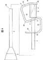
図1および図2は、それぞれ、本発明の第1実施形態のプロテクタを示す側面図である。なお、以下では、図1および図2中の針先側を「先端」、ハブ側を「基端」とし、先端を上にした場合の左側を「一端」、右側を「他端」として説明する。
図1および図2に示す穿刺具1Aは、先端部に鋭利な針先41を有する針管(針体)4と、この針管4に装着され、針管4の針先41を収納可能なプロテクタ2Aと、針管4の基端部に固定されたハブ5とを備えている。以下、各部の構成について説明する。
針管4は、中空針であり、例えば、ステンレス鋼、アルミニウムまたはアルミニウム合金、チタンまたはチタン合金のような金属材料で構成されている。針管4の先端部には、鋭利な針先41が形成されている。この針先41の形状は特に限定されず、本実施形態では、針管4の軸線に対し所定角度傾斜した刃面を有する形状をなしている。
針管4の基端部には、ハブ5が液密に固着(固定)され、針管4の内腔とハブ5の内部とが連通している。
針管4のハブ5に対する固着方法としては、例えば、カシメ、融着(熱融着、高周波融着等)、接着剤による接着等の方法が挙げられる。
ハブ5は、ほぼ筒状の部材で構成され、好ましくは透明(無色透明)、着色透明または半透明の樹脂で構成され、内部の視認性が確保されている。
このハブ5は、基端方向に向かってその外径および内径が漸増するテーパ状をなしている。このテーパ状部分には、例えば、シリンジ(図示せず)の先端部が挿入され、穿刺具1Aがシリンジに装着される。
ハブ5の構成材料は、特に限定されず、例えば、ポリエチレン、ポリプロピレン、ポリブタジエン、エチレン−酢酸ビニル共重合体等のポリオレフィン、ポリ塩化ビニル、ポリウレタン、ポリスチレン、ポリメチルメタクリレート、ポリカーボネート、ポリアミド、ポリエチレンテレフタレート、ポリブチレンテレフタレート等のポリエステル、アクリル系樹脂、ABS樹脂、AS樹脂、アイオノマー、ポリアセタール、ポリフェニレンサルファイド、ポリエーテルエーテルケトン等の各種樹脂材料が挙げられる。
プロテクタ2Aは、弾性を有する板状部材を変形して(曲げ加工して)形成されており、長手方向ほぼ中央に位置する第1の部位(ブレーキ部)21と、針元側(基端側)に位置する第2の部位22と、針先側(先端側)に位置する第3の部位23と、第1の部位21と第2の部位22との他端部同士を接続する後方接続部24と、第1の部位21と第3の部位23との一端部同士を接続する前方接続部25とを有している。これにより、プロテクタ2Aは、全体形状としてほぼS字状をなしている。
プロテクタ2Aの第1の部位21には、ほぼ円形をなす第1の孔31が設けられており、第2の部位22には、第2の孔32が設けられており、第3の部位23には、第3の孔33が設けられている。これら第1の孔31、第2の孔32および第3の孔33は、針管4が貫通可能な孔である。
また、図示の構成では、第3の部位23の他端部には、内側に湾曲(屈曲)するカバー部26が設けられている。
このようなプロテクタ2Aは、穿刺具1Aの使用時(生体などに穿刺するとき)には、図1に示す姿勢、すなわち第1の孔31、第2の孔32および第3の孔33を針管4が貫通(挿通)した姿勢(この姿勢を以下、「第1の姿勢」と言う。)になっている。この第1の姿勢のとき、プロテクタ2Aは、針管4に対し長手方向に移動可能である。通常は、図1に示すように、プロテクタ2Aが針管4の基端部に位置する状態(この状態を以下、「使用状態」と言う。)で穿刺具1Aを使用する。
図示の構成では、第1の姿勢のとき、第1の部位21、第2の部位22および第3の部位23は、それぞれ針管4に対しほぼ垂直になっており、後方接続部24および前方接続部25は、それぞれ針管4とほぼ平行になっている。これにより、第1の姿勢において第1の部位21と後方接続部24とのなす角度は、ほぼ直角になっている。
これに対し、プロテクタ2Aが針管4に装着されず外力がかかっていない自然状態(外力を付与しない状態)においては、第1の部位21と後方接続部24とのなす角度は、図2に示す状態よりも小さく設定されている。すなわち、プロテクタ2Aは、第1の部位21と後方接続部24とが開くように変形(弾性変形)させられた状態で、針管4に装着されている。
この変形により、プロテクタ2Aが針管4に装着された状態では、第1の部位21は、針管4に対する傾斜角度(図1中のθおよび図2中のθ’で示す角度)が小さくなるような方向に付勢されている。換言すれば、プロテクタ2Aにおける第1の部位21と後方接続部24との間の部分は、その弾性によって第1の部位21の針管4に対する傾斜角度が小さくなるような方向に第1の部位21を付勢する付勢手段となっている。
ここで、第1の部位21の針管4に対する傾斜角度は、第1の部位21と針管4とがなす角のどちら側を選択するかによって2つの大きさで表すことができるが、本明細書において「第1の部位21の針管4に対する傾斜角度」とは、後述する第2の姿勢のときに90°未満になる角(小さい方の角)の角度を指すものとする。すなわち、本実施形態においては、図1中のθおよび図2中のθ’で示す角度である。この角度を以下、「第1の部位傾斜角度」と言う。
図1に示す第1の姿勢においては、第3の部位23に形成された第3の孔33を針管4が貫通していることにより、前記付勢手段の付勢力によって第1の部位傾斜角度が小さくなるようにプロテクタ2Aが変形することが阻止され、前述したように第1の姿勢における第1の部位傾斜角度θは、ほぼ直角に保たれている。換言すれば、第3の孔33は、第1の姿勢において、針管4と係合することにより、第1の部位傾斜角度θをほぼ直角に規定する傾斜規定手段となっている。
なお、本実施形態における前記傾斜規定手段は、第3の孔33に限らず、針管4が貫通して係合可能な貫通部であればよく、例えば周の一部が欠損したフック状のものとなっていてもよい。
このような使用状態(第1の姿勢)から、プロテクタ2Aを針管4に対し先端方向に移動させていき、針先41が第3の部位23の第3の孔33を通過すると、針管4と第3の孔33との係合が解除される。これにより、プロテクタ2Aは、前記付勢手段の付勢力によって、弾性的に図2に示す姿勢(この姿勢を以下、「第2の姿勢」と言う。)に変位(変形)する。
すなわち、第2の姿勢では、プロテクタ2Aは、第1の姿勢のときと比べ、第1の部位21が後方接続部24(針管4)に対し図1中反時計方向に回動するように変位(変形)している。これにより、第1の部位傾斜角度は、第1の姿勢のときより小さくなっており、θ’<θなるθ’となっている。
これに伴なって、第3の部位23、前方接続部25およびカバー部26も後方接続部24(針管4)に対し変位(回動)しており、針管4の針先41の末端は、カバー部26によって覆われた状態となっている。このように、プロテクタ2Aが針管4の針先41を覆った状態、すなわち図2に示す状態を以下、「針先収納状態」と言う。
このような第2の姿勢(針先収納状態)のとき、プロテクタ2Aの第1の部位21が針管4に対してブレーキとして機能することにより、プロテクタ2Aは、針管4の長手方向に沿った相対的な移動が禁止(阻止)される。すなわち、前記付勢手段の付勢力によって第1の部位傾斜角度が第1の姿勢のときより小さくなることにより、第1の孔31の内面が針管4の外周面に圧接され、第1の孔31の内面と針管4の外周面との間の摩擦力が発生または増大する。この摩擦力が、プロテクタ2Aに制動力として作用し、針管4の長手方向に沿ったプロテクタ2Aの移動を禁止(阻止)する。
このような構成により、穿刺具1Aにおいては、一旦針先収納状態になると、針管4の針先41がプロテクタ2Aを超えて突出することがない。これにより、廃棄処理等に際し、誤刺を防止することができ、安全性が高い。
また、プロテクタ2Aは、第1の部位21のブレーキ作用によって針管4に対する長手方向の移動が禁止されるので、針管4にプロテクタ2Aを係止するための特別な構造(例えば、局所的に外径を太くしたり、外周部に凸部を設けたり、ハブ5とプロテクタ2Aとをヒモで結んだりするような構造)が不要である。これにより、針管4の先端部を特別な加工等を施さない円滑な外周面を有するものとすることができ、強度の低下や刺通抵抗の増大を招くことがない。また、同様の理由からプロテクタ2Aは、既存の針体と組み合わせて使用することもでき、汎用性が高い。
また、本実施形態のプロテクタ2Aは、第2の姿勢においてプロテクタ2Aの先端部を基端方向に押圧したとき、第1の部位21(第1の孔31近傍の板状部材)に対し、第1の部位傾斜角度θ’がより小さくなるような力を作用する手段を有する。
すなわち、プロテクタ2Aに対し図2中の矢印Aで示すような押圧力を加えたとき、この押圧力Aは、第3の部位23および前方接続部25を介して第1の部位21に伝達され、第1の部位傾斜角度θ’が小さくなるように作用する。これにより、第1の孔31の内面と針管4の外周面との間の摩擦力(プロテクタ2Aに作用する制動力)がさらに増大して押圧力Aに対抗し、プロテクタ2Aの移動をより確実に禁止(阻止)する。このため、押圧力Aを加えた場合にも、針先41がプロテクタ2Aを超えて突出することがより確実に防止され、特に安全性が高い。
なお、特に強い押圧力Aが作用して、万一プロテクタ2Aが基端方向に僅かに移動した場合にも、針先41は、カバー部26の内面に当接するため、針先41がプロテクタ2Aを超えて突出することはない。
また、プロテクタ2Aに対し図2中の矢印Bで示すような押圧力を加えたときにも、同様に、第1の部位傾斜角度θ’が小さくなるように作用する。これにより、押圧力Bを加えた場合にも、プロテクタ2Aが針先41から離脱する(抜け落ちる)ことがより確実に防止され、特に安全性が高い。
第1の姿勢における第1の部位傾斜角度θは、特に限定されないが、60°以上であるのが好ましく、本実施形態のようにほぼ直角であるのがより好ましい。また、第1の孔31の内径Dは、針管4の外径dによってもその好ましい大きさは異なるが、通常、針管4の外径dより0.01〜1mm程度大きいのが好ましく、0.05〜0.2mm程度大きいのがより好ましい。
第1の姿勢における第1の部位傾斜角度θや第1の孔31の内径Dが前記範囲にあることにより、第2の姿勢において、第1の孔31の内面と針管4の外周面との間の摩擦力(プロテクタ2Aに作用する制動力)が大きくなり、針管4の長手方向に沿った相対的な移動がより確実に禁止(阻止)される。
なお、本発明においては、第1の孔31は、周の一部が欠損したもの(C字状のものなど)であってもよい(第2の孔32についても同様)。
また、第2の孔32や第3の孔33の形状は、針管4に対し摺動可能であれば円形に限らないが、円形である場合には、その内径は、第1の姿勢における摺動抵抗を軽減する観点から、第1の孔31の内径Dより0.05〜1mm程度大きいのが好ましい。
プロテクタ2Aを形成する板状部材(第1の部位21)の厚さは、その構成材料や針管4の外径等によってもその好ましい値は異なるが、通常、0.05〜2mm程度であるのが好ましく、0.06〜0.2mm程度であるのがより好ましい。前記範囲において、比較的厚いものとした場合には、第2の姿勢においてプロテクタ2Aに作用する制動力や針先41の保護性が特に優れたものとなり、比較的薄いものとした場合には、加工性や第1の姿勢における針管4に対する摺動のし易さが特に優れたものとなる。
プロテクタ2Aを形成する板状部材の構成材料としては、特に限定されず、例えば、ステンレス鋼、アルミニウムまたはアルミニウム合金、鉄、ニッケル合金、チタンまたはチタン合金、銅または銅系合金等の各種金属材料や、ポリエチレン、ポリプロピレン、ポリブタジエン、エチレン−酢酸ビニル共重合体等のポリオレフィン、ポリ塩化ビニル、ポリウレタン、ポリスチレン、ポリメチルメタクリレート、ポリカーボネート、ポリアミド、ポリエチレンテレフタレート、ポリブチレンテレフタレート等のポリエステル、アクリル系樹脂、ABS樹脂、AS樹脂、アイオノマー、ポリアセタール、ポリフェニレンサルファイド、ポリエーテルエーテルケトン等の各種樹脂材料が挙げられるが、各種金属材料であるのが好ましい。また、上述したような材料を2種以上組み合わせて使用してもよい。
次に、穿刺具1Aの使用方法の一例について、図1および図2に基づいて詳細に説明する。
まず、穿刺具1Aを使用状態(図1に示す状態)とし、ハブ5の基端部にシリンジ(図示せず)の先端部を挿入し、穿刺具1Aをシリンジに装着する。この状態で、針管4を患者の血管(生体)に穿刺し、シリンジが備えるプランジャを操作し、患者に対して血液の採取あるいは薬液を注入する。
次に、血液の採取あるいは薬液の注入を終了すると、針管4を患者の血管から抜き取る。
この後、ハブ5を手で把持して固定し、他方の手またはピンセット等を用いて、プロテクタ2Aを針管4に対し先端方向に移動させる。
ここで、従来の穿刺操作では、針先41を生体から抜き取った後、針管4にキャップを被せていたが、キャップの一端部の開口内に針管4をその針先41から挿入して行うため、針先41が該開口を外れた場合には、キャップを摘んでいる指を針管4の針先41で誤刺するという事故が生じるおそれがあった。しかし、本発明では、プロテクタ2Aが針管4の先端方向に移動して針先41を覆うため、前述したような誤刺を有効に防止することができる。
プロテクタ2Aの先端方向への移動により、針管4の針先41が第3の孔33を通過すると、針管4と第3の孔33との係合が解除され、プロテクタ2Aは、弾性的に(自身の弾性により)変形して、図2に示す第2の姿勢となる。
プロテクタ2Aが第2の姿勢となると、第1の部位21のブレーキ作用によって、プロテクタ2Aは、針管4の長手方向に沿った移動が禁止(阻止)され、針先41が第1の孔31を通過する前に針管4に対し停止(静止)する。これにより、第2の穿刺具1Aは、図2に示す針先収納状態となる。
針管4の針先41がプロテクタ2A内に収納されたら、ハブ5に装着しているシリンジを取り外し、穿刺具1Aとシリンジとを分離する。そして、穿刺具1Aおよびシリンジは、それぞれ別個に廃棄に供される。この穿刺具1Aは、前述したように、針先収納状態では針先41がプロテクタ2A内に収納されており、針先41がプロテクタ2Aを超えて突出したり、プロテクタ2Aが針先41から離脱することがない。これにより、廃棄処理等に際し、針先41で誤って手指等を刺すという事故が防止され、安全性が高い。
<プロテクタの第2実施形態>
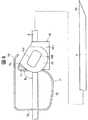
図3および図4は、それぞれ、本発明の第2実施形態のプロテクタを有する穿刺具(注射針)を示す側面図である。なお、以下の説明では、図3および図4中の針先側を「先端」、ハブ側を「基端」とし、先端を上にした場合の左側を「一端」、右側を「他端」として説明する。
以下、これらの図を参照して本発明のプロテクタの第2実施形態について説明するが、前述した実施形態との相違点を中心に説明し、同様の事項はその説明を省略する。
本実施形態のプロテクタ2Bは、第2の姿勢において針管4の針先41の横ずれを防止する横ずれ防止部材としての筒状部材6を有すること以外は、前記第1実施形態のプロテクタ2Aと同様である。すなわち、本実施形態のプロテクタ2Bは、前記第1実施形態のプロテクタ2Aと同様のプロテクタ本体(本体部)2’と、筒状部材6とで構成されている。
また、本実施形態の穿刺具1Bは、このようなプロテクタ2Bと、前記第1実施形態と同様の針管4およびハブ5とで構成されている。
前記横ずれ防止部材としての筒状部材6は、針管4が貫通(挿通)可能な中空部を有する円筒状をなし、プロテクタ本体2’の第3の部位23に形成された第3の孔33と第1の部位21に形成された第1の孔31との間に位置している。
すなわち、図3に示す第1の姿勢(使用状態)においては、針管4は、プロテクタ2Bの第2の孔32、第1の孔31、筒状部材6の中空部および第3の孔33をこの順に貫通した状態となっている。
そして、図4に示す第2の姿勢(針先収納状態)においては、針先41は、筒状部材6の内部に位置し、筒状部材6で覆われた状態となっている。
また、筒状部材6の先端開口は、プロテクタ本体2’のカバー部26により覆われて、封止されている。すなわち、筒状部材6は、第2の姿勢において針先41を覆うキャップ部材としての機能も併せ持っている。
このような構成により、本実施形態のプロテクタ2Bでは、前記第1実施形態のプロテクタ2Aと同様の効果が得られるとともに、第2の姿勢において、針先41が横方向(長手方向と垂直な方向)にずれることが防止される。これにより、針先収納状態において、プロテクタ2Bに対し例えば横方向に強い外力が作用したような場合であっても針先41の突出をより確実に防止することができ、より安全性が高い。
また、針先41の全体が筒状部材6およびカバー部26で覆われているので、針先41の周りや内部に残留した血液(体液)が垂れ落ちるのを防止(抑制)することができ、血液(体液)による汚染を効果的に防止することができる。
筒状部材6の構成材料としては、特に限定されず、例えば、ステンレス鋼、アルミニウムまたはアルミニウム合金、チタンまたはチタン合金、鉄、ニッケル合金、銅または銅系合金等の各種金属材料や、ポリエチレン、ポリプロピレン、ポリブタジエン、エチレン−酢酸ビニル共重合体等のポリオレフィン、ポリ塩化ビニル、ポリウレタン、ポリスチレン、ポリメチルメタクリレート、ポリカーボネート、ポリアミド、ポリエチレンテレフタレート、ポリブチレンテレフタレート等のポリエステル、アクリル系樹脂、ABS樹脂、AS樹脂、アイオノマー、ポリアセタール、ポリフェニレンサルファイド、ポリエーテルエーテルケトン等の各種樹脂材料や、各種ゴム材料、各種熱可塑性エラストマー等が挙げられ、これらの材料を2種以上組み合わせて使用してもよい。
筒状部材6の構成材料を各種ゴム材料や各種熱可塑性エラストマーを含むものとした場合には、第2の姿勢においてカバー部26が筒状部材6の先端開口に対してより密着し、針先41の周りや内部に残留した血液(体液)が垂れ落ちるのをより効果的に防止することができる。
<プロテクタの第3実施形態>
図5および図6は、それぞれ、本発明の第3実施形態のプロテクタを有する穿刺具(注射針)を示す側面図である。なお、以下の説明では、図5および図6中の針先側を「先端」、ハブ側を「基端」とし、先端を上にした場合の左側を「一端」、右側を「他端」として説明する。
以下、これらの図を参照して本発明のプロテクタの第3実施形態について説明するが、前述した実施形態との相違点を中心に説明し、同様の事項はその説明を省略する。
本実施形態のプロテクタ2Cは、前記横ずれ防止部材としての筒状部材の形状が異なること以外は、前記第2実施形態のプロテクタ2Bと同様である。すなわち、本実施形態のプロテクタ2Cは、前記第1実施形態のプロテクタ2Bと同様のプロテクタ本体(本体部)2’’と、筒状部材6とで構成されている。
また、本実施形態の穿刺具1Cは、このようなプロテクタ2Cと、前記第1実施形態と同様の針管4およびハブ5とで構成されている。
前記横ずれ防止部材としての筒状部材6は、針管4が貫通(挿通)可能な中空部を有する円筒状をなし、プロテクタ本体2’’の第3の部位23に形成された第3の孔33と第1の部位21に形成された第1の孔31との間に位置している。
すなわち、図5に示す第1の姿勢(使用状態)においては、針管4は、プロテクタ2の第2の孔32、第1の孔31、筒状部材6の中空部および第3の孔33をこの順に貫通した状態となっている。
この筒状部材6の基端面は、針管4と垂直な面に対して傾斜した傾斜面61となっている。この傾斜面61の傾斜方向は、図6に示す第2の姿勢(針先収納状態)における第1の部位21の傾斜方向と同じになっている。
なお、図示を省略するが、プロテクタ2Cには、筒状部材6のプロテクタ本体2’’に対する回転を防止する回転防止手段が設けられている。
このような構成により、本実施形態のプロテクタ2Cでは、前記第1実施形態のプロテクタ2Aと同様の効果が得られるとともに、前記第2実施形態のプロテクタ2Bと同様に、第2の姿勢において針先41が横方向(長手方向と垂直な方向)にずれることが防止される効果が得られる。
さらに、本実施形態においては、第2の姿勢においてプロテクタ2Cに対し図6中の矢印Cで示すような押圧力が作用したとき、すなわち筒状部材6の先端部を基端方向に押圧したときに、第1の部位21(第1の孔31近傍の板状部材)に対し、第1の部位傾斜角度θ’がより小さくなるような力を作用する手段(傾斜面61)を有する。
すなわち、前記押圧力Cは、筒状部材6の傾斜面61を介して第1の部位21に伝達され、第1の部位傾斜角度θ’が小さくなるように作用する。これにより、第1の孔31の内面と針管4の外周面との間の摩擦力(プロテクタ2Cに作用する制動力)がさらに増大して押圧力Cに対抗し、プロテクタ2Cの移動をより確実に禁止(阻止)する。このため、押圧力Cを加えた場合にも、針先41がプロテクタ2を超えて突出することがより確実に防止され、特に安全性が高い。
なお、本実施形態においても前記第2実施形態と同様に、第2の姿勢においてカバー部26が筒状部材6の先端開口を封止するような構成としてもよい。
<プロテクタの第4実施形態>
図7および図10は、本発明の第4実施形態のプロテクタを示す断面側面図であり、図8および図9は、それぞれ図7に示すプロテクタの側面図と斜視図である。なお、以下の説明では、図7、図8および図10において、針先側を「先端」、ハブ側を「基端」とし、先端を上にした場合の左側を「一端」、右側を「他端」として説明する。
これらの図において、プロテクタ7Aは、先端部に鋭利な針先41を有し、その基端部がハブ(示されていない)に固定された針管(針体)4に装着されて穿刺具の一部をなしている。
図7ないし図9において、本実施形態のプロテクタ7Aは、上記第1〜第3の実施形態のプロテクタの第1の姿勢に相当する姿勢、すなわち、針管4の長手方向(軸方向)に沿って相対的に移動可能な姿勢(本実施形態を含めて以下の実施形態でも第1の姿勢と呼ぶ。)で示されている。
一方、図10において、本実施例のプロテクタ7Aは、上記第1〜第3の実施形態のプロテクタの第2の姿勢に相当する姿勢、すなわち、針管4の針先41を覆った状態で、針管4の長手方向に沿った相対的な移動が禁止される姿勢(本実施形態を含めて以下の実施形態でも第2の姿勢と呼ぶ。)で示されている。
本実施形態のプロテクタ7Aは、金属材料で構成された板状部材を変形して(曲げ加工して)形成されたプロテクタ本体7’と、該プロテクタ本体7’に固定(固着)されたプラスチック部材10とを有している。
図7に示すように、プロテクタ本体7’は、第1の孔(孔)81が形成された第1の部位(ブレーキ部)71と、該第1の部位71の基端側(針元側)に設けられ、第2の孔82が形成された第2の部位72と、第1の部位71と第2の部位72との他端部同士をつなぐ第3の部位73とを有している。
すなわち、側面視(図7)において、第1の部位71と、第2の部位72と、第3の部位73とは、全体として略「コ」字状(または略「C」字状)をなすように形成されている。
第1の孔81および第2の孔82には、針管4が貫通している。第1の孔81の形状は、円形であることが好ましい。
また、プロテクタ本体7’は、第1の部位71の一端部から先端方向に延びるように設けられた第4の部位74と、該第4の部位74の両方の側部からそれぞれ他端方向にほぼ平行に延びるように設けられた第5の部位75、75とを有している。
すなわち、図7の側面視に対して針先側から正面視した場合に、第4の部位74と、第5の部位75、75とは、全体として略「コ」字状をなすように形成されており、両第5の部位75、75は、針管4を両側から挟むように位置している。これらの位置関係は、図9に明確に示されている。
図8および図9に示すように、第5の部位75、75には、それぞれ、略長方形状(楕円形状)の長孔751が形成されている。
また、図7ないし図9に示すように、本実施形態では、第4の部位74は、第1の姿勢において先端方向に向かって針管4に近づくように傾斜して設けられている。これにより、図10に示すように、第2の姿勢に変位(変形)したときに、第4の部位74が外側に張り出すことがないため、プロテクタ7A全体の小型化に寄与する。
このようなプロテクタ本体7’は、金属材料で構成されている。これにより、第2の姿勢において、第1の孔81の内面と、針管4の表面との摩擦力が十分に大きくなり、第1の部位71(ブレーキ部)のブレーキ作用が確実に発揮される。プロテクタ本体7’を構成する金属材料としては、特に限定されないが、例えば、ステンレス銅、アルミニウムまたはアルミニウム合金、鉄、ニッケル合金、チタンまたはチタン合金、銅または銅系合金等の各種金属材料が挙げられる。
なお、本実施形態では、プロテクタ本体7’は、その各部が一体的に形成されたものとなっているが、本発明では、プロテクタ本体7’が2以上の部品で構成されていてもよい。
プロテクタ本体7’の両第5の部位75、75の間には、プラスチック部材10が設置されている。図7に示すように、プラスチック部材10は、第5の部位75、75の内側にそれぞれ配置された側壁部101、101と、両側壁部101、101の他端部同士を連結する連結壁102とを有している。
側壁部101、101は、それぞれ、第5の部位75、75とほぼ平行に設けられている。すなわち、側壁部101、101と、連結壁102とは、正面視した場合に、全体として略「コ」字状をなすように形成されている。
このような構成により、本実旗形態のプロテクタ7Aは、側壁部101、101と、連結壁102とで囲まれて形成される針先収納空間9を有している。図10に示すように、第2の姿勢のとき、針管4の針先41は、この針先収納空間9に収納される。
また、針先41は、第2の姿勢において針先収納空間9に収納されたとき、第1の部位71と、第4の部位74と、側壁部101、101と、連結壁102とによって、はぼ全周から覆われる。これにより、針先41の表面や内部に残留した血液などが作業者や周囲の物に付着することが防止され、汚染を防止することができる。
側壁部101、101からは、外側に突出する突出部105、105がそれぞれ設けられている。図8および図9に示すように、この突出部105は、第5の部位75の長孔751に対応した形状をなしており、各突出部105、105は、それぞれ、長孔751、751に挿入(嵌合)している。これにより、プラスチック部材10は、プロテクタ本体7’に対し固定(固着)されている。なお、プラスチック部材10とプロテクタ本体7’との固定方法は、このような構成に限らず、例えば、接着剤による接着等、いかなる方法であってもよいことは言うまでもない。
プラスチック部材10は、さらに、針先収納空間9を先端側から覆う先端壁103を有している。図9および図10に示すように、この先端壁103の図7中の上側には、切欠き部106が形成されている。第1の姿勢のとき、針管4は、この切欠き部106を通過して、プロテクタ7Aから先端方向に突出する。
切欠き部106の縁部は、第1の姿勢のとき針管4に当接する針体当接部104となっている。針体当接部104は、針体表面に対応するような円弧状の湾曲面形状であることが好ましい。
針体当接部104は、第1の姿勢のとき、針管4に当接する。すなわち、後述するように、プロテクタ本体7’の第1の部位71と第3の部位73との一部の弾性(バネ性)により、プラスチック部材10は、図7中の反時計方向に回動するような方向に付勢されており、この付勢力により、第1の姿勢のとき、針体当接部104は、針管4に圧接された状態になっている。
なお、プラスチック部材10は、図示のような構成に限らず、例えば、針体当接部を孔として有する筒状の形状をなすようなものであってもよい。
このような針体当接部104を含むプラスチック部材10は、樹脂材料(合成樹脂材料)で構成されている。これにより、第1の姿勢において、針体当接部104と針管4の表面との間の摩擦抵抗が軽減され、プロテクタ7Aの針管4に対する摺動抵抗が小さくなる。その結果、第1の姿勢のとき、プロテクタ7Aは、針管4の長手方向(軸方向)に沿って円滑に(比較的小さい操作力で)移動することができる。
プラスチック部材10(針体当接部104)を構成する樹脂材料としては、特に限定されないが、ポリエチレン、ポリプロピレン、ポリウレタン、ポリスチレン、ポリカーボネート、ポリエステル、ABS樹脂、AS樹脂、フッ素系樹脂、ポリアセタール等の各種樹脂材料が挙げられる。
なお、本発明では、好ましくは、少なくとも針体当接部104が前述したような樹脂材料で構成されていればよい。また、例えば前述したフッ素系樹脂のような特に摩擦係数(摩擦抵抗)の小さい材料で針体当接部104の表面を構成(被覆)してもよい。
なお、針体当接部104の針管4に対する接触面は、例えば、平面状、「V」字状、「コ」字状などであってもよい。
このようなプロテクタ7Aは、穿刺具の使用時(生体などに穿刺するとき)には、図7ないし図9に示す第1の姿勢で、針管4の針元側に位置した状態とされる。
この第1の姿勢においては、針管4は、第2の孔82および第1の孔81を貫通し、さらに、針先収納空間9および切欠き部106を通過してプロテクタ7Aの先端から突出する。
また、第1の姿勢のとき、第1の部位71と、第2の部位72とは、それぞれ、針管4に対しほぼ垂直な姿勢になっている。
プロテクタ7Aは、このような第1の姿勢から図10に示す第2の姿勢に変位(変形)して、針先41を覆うことができる。この第2の姿勢においては、プロテクタ本体7’における第1の部位71と第3の部位73とのなす角度が第1の姿勢のときよりも小さくなる。すなわち、プロテクタ7Aは、第1の部位71と第3の部位73とが閉じるように(第1の部位71が第3の部位73に近づくように)変形することにより、第1の姿勢から第2の姿勢に変位(変形)する。
このような第1の姿勢から第2の姿勢への変位(変形)は、プロテクタ本体7’における第1の部位71と第3の部位73との一部の弾性(弾性力)によって生じるようになっている。
すなわち、プロテクタ7Aに外力を付与しない自然状態(プロテクタ7Aを針管4に装着していない状態)においては、第1の部位71と第3の部位73とのなす角度は、図10に示す状態よりもさらに小さくなっており、プロテクタ7Aは、このような自然状態から第1の部位71と第3の部位73とが開くように(第1の部位71が第3の部位73から遠ざかるように)変形(弾性変形)した状態とされて針管4に装着されている。
このような構成により、プロテクタ7Aが針管4に装着された状態では、第1の部位71は、針管4に対する傾斜角度(図8中のθ1および図10中のθ1’で示す角度)が小さくなるような方向に付勢されている。すなわち、プロテクタ7Aにおける第1の部位71と第3の部位73との一部は、その弾性によって第1の部位71の針管4に対する傾斜角度θが小さくなるような方向に第1の部位71を付勢する付勢手段となっている。
図7に示すように、第1の姿勢においては、針体当接部104が針管4の表面に当接していることにより、前記付勢手段の付勢力によって第1の部位傾斜角度が小さくなるようにプロテクタ7Aが変形することが阻止されており、これにより、前述したように第1の姿勢における第1の部位傾斜角度θ1は、ほぼ直角に保たれている。本明細書において、「第1の部位71の針管4に対する傾斜角度」は、上記第1実施形態における「第1の部位21の針管4に対する傾斜角度」と同様に定義する。
よって、第1の姿勢では、第1の孔81と、針管4との間には、隙間が形成されており、第1の孔81の内面と、針管4の表面との間の摩擦力は、実質的に作用していないか、または、比較的小さい状態になっている。すなわち、第1の姿勢では、第1の部位71がブレーキ作用を生じないようになっている。
このように、針体当接部104は、第1の姿勢のとき針管4に当接することにより、第1の部位傾斜角度が小さくなる(変化する)ことを防止して、第1の部位71のブレーキ作用を留保する機能を有している。
すなわち、第1の姿勢では、プロテクタ7Aは、針体当接部104が針管4に当接することにより、ブレーキ作用留保状態になっている。
このように、第1の姿勢では、針体当接部104は、前記付勢手段の付勢力により、針管4の表面に圧接された状態となっているが、本発明では、前述したように針体当接部104が樹脂材料で構成されていることから、プロテクタ7Aは、針管4に対し円滑に(比較的小さい操作力で)移動可能になっている。
第1の姿勢から、プロテクタ7Aを針管4に対し相対的に先端方向に移動させていき、針体当接部104が針先41を通過すると、針体当接部104が針管4から離反(離間)する。これにより、プロテクタ7Aは、ブレーキ作用留保状態が解除され、前記付勢手段の付勢力によって、弾性的に第2の姿勢に変位(変形)する。
第2の姿勢では、プロテクタ7Aは、第1の姿勢のときと比べ、第1の部位71が第3の部位73(針管4)に対し図7および図8中反時計方向に回動するように変位(変形)している。これにより、図10に示すように、第1の部位傾斜角度は、第1の姿勢のときより小さくなっており、θ1’<θ1なるθ1’となっている。
これに伴なって、第4の部位74、第5の部位75およびプラスチック部材10、第3の部位73(針管4)に対し変位(回動)しており、針先41の先端は、先端壁103によって先端側から覆われた状態となっている。
このような第2の姿勢においては、プロテクタ7Aの第1の部位71が針管4に対してブレーキとして機能することにより、プロテクタ7Aは、針管4の長手方向に沿った相対的な移動が禁止(阻止)される。すなわち、前記付勢手段の付勢力によって第1の部位傾斜角度が第1の姿勢のときより小さくなることにより、第1の孔81の内面が針管4の表面(外周面)に圧接され、第1の孔81の内面と針管4の表面(外周面)との間の摩擦力が発生または増大する。この摩擦力が、プロテクタ7Aに制動力として作用し、針管4の長手方向に沿ったプロテクタ7Aの移動を禁止(阻止)する。
このような構成により、針先41が針先収納空間9に収納される(第2の姿勢になる)と、針先41は、プロテクタ7Aを超えて突出することがない。
第1の姿勢における第1の部位傾斜角度θ1は、特に限定されないが、60°以上であるのが好ましく、本実施形態のようにほぼ直角であるのがより好ましい。
また、第1の孔81の内径Dは、針管4の外径dによってもその好ましい大きさは異なるが、通常、針管4の外径dより0.01〜1mm程度大きいのが好ましく、0.05〜0.2mm程度大きいのがより好ましい。
第1の姿勢における第1の部位傾斜角度θ1や第1の孔81の内径Dが前記範囲にあることにより、第2の姿勢において、第1の孔81の内面と針管4の表面との間の摩擦力(プロテクタ7Aに作用する制動力)が大きくなり、針管4の長手方向に沿った相対的な移動がより確実に禁止(阻止)される。
なお、本発明においては、第1の孔81は、周方向の一部が欠損したもの(C字状のものなど)であってもよい(第2の孔82についても同様)。
また、第2の孔82の形状は、針管4に対し摺動可能であれば円形に限らないが、円形である場合には、その内径は、第1の姿勢における摺動抵抗を軽減する観点から、第1の孔81の内径Dより0.05〜1mm程度大きいのが好ましい。
また、本発明では、第2の孔82の近傍の部位(針管4との接触面)を前述したような樹脂材料で構成したり、曲げ加工を施すこと等により針管4との接触面を滑らかにしてもよい。これにより、第2の孔82の内面と、針管4の表面との間の摩擦力が軽減される。よって、第1の姿勢におけるプロテクタ7Aの針管4に対する摺動抵抗をより軽減することができ、その結果、プロテクタ7Aを針管4に対し相対的に先端方向に移動する操作(プロテクタ7Aで針先41を覆うする操作)をさらに容易、円滑に行うことができる。
プロテクタ本体7’を形成する板状部材(特に、第1の部位71)の厚さは、その構成材料や針管4の外径等によってもその好ましい値は異なるが、通常、0.05〜2mm程度であるのが好ましく、0.06〜0.2mm程度であるのがより好ましい。前記範囲において、比較的厚いものとした場合には、第2の姿勢においてプロテクタ7Aに作用する制動力や針先41の保護性が特に優れたものとなり、比較的薄いものとした場合には、加工性や第1の姿勢における針管3に対する摺動のし易さが特に優れたものとなる。
このようなプロテクタ7Aは、第2の姿勢においてその先端部(プラスチック部材10等)を基端方向に押圧したとき、第1の部位71(第1の孔81近傍の板状部材)に対し、第1の部位傾斜角度θ1’がより小さくなるような力を作用する手段を有する。
すなわち、例えばプラスチック部材10の先端部に対し図10中の矢印Aで示すような押圧力を加えたとき、この押圧力Aは、第4の部位74を介して第1の部位71に伝達され、第1の部位傾斜角度θ1’が小さくなるように作用する。これにより、第1の孔81の内面と針管4の表面との間の摩擦力(プロテクタ7Aに作用する制動力)がさらに増大して前記押圧力Aに対抗し、プロテクタ7Aの移動をより確実に禁止(阻止)する。
なお、特に強い押圧力Aが作用して、プロテクタ7Aが万一基端方向に僅かに移動した場合にも、針先41は、連結壁102と先端壁103との角部の内側(針先受け部)に当接するため、針先41がプロテクタ7Aを超えて突出することはない。
次に、プロテクタ7Aの使用方法の一例について、詳細に説明する。
[1] 第1の姿勢にあるプロテクタ7Aを針管4の基端側に位置させた状態で、針管4を患者の血管(生体)等に穿刺し、血液の採取や薬液の注入を行う。
[2] 血液の採取あるいは薬液の注入を終了したら、針管4を患者の血管から抜き取る。
[3] 次いで、手またはピンセット等を用いて、プロテクタ7Aを針管4に対し先端方向に移動させる。このとき、本発明では、前述したように、針体当接部104が樹脂材料で構成されていることにより、プロテクタ7Aを比較的小さい操作力で針管4に対し先端方向に移動させることができ、この操作を円滑、迅速かつ容易に行うことができる。
[4] プロテクタ7Aの先端方向への移動により、針体当接部104が針先41を通過して、針管4から離反すると、プロテクタ7Aは、弾性的に(自身の弾性により)変形して、図10に示す第2の姿勢となる。
プロテクタ7Aが第2の姿勢となると、第1の部位71のブレーキ作用によって、プロテクタ7Aは、針管4の長手方向に沿った移動が禁止(阻止)され、針先41が第1の孔81を通過する前に針管4に対し停止(静止)する。
[5] 針管4の針先41がプロテクタ7A内(針先収納空間9)に収納されたら、これらは、廃棄に供される。
このとき、前述したように、針先41は、プロテクタ7A内に収納されており、針先41がプロテクタ7Aを超えて突出したり、プロテクタ7Aが針先41から離脱することがない。これにより、廃棄処理等に際し、針先41で誤って手指等を刺すという事故が防止される。
<プロテクタの第5実施形態>
図11は、本発明の第5実施形態のプロテクタを示す断面側面図であり、プロテクタは第2の姿勢で示されている。
以下、同図を参照して本発明のプロテクタの第5実施形態について説明するが、前述した第4実施形態との相違点を中心に説明し、同様の事項はその説明を省略する。
本実施形態のプロテクタ7Bは、プラスチック部材10(針体当接部104近傍の部位)を覆うカバー部1000、1000を有していること以外は、前記第4実施形態と同様である。
カバー部1000、1000は、第2の部位72の一端部から先端方向に延びるように設けられた第6の部位76の両方の側部からそれぞれ他端方向(図10中の下方向)に延びるように設けられており、第1の部位71や第2の部位72等に対してほぼ垂直に配置されている。すなわち、両カバー部1000、1000は、ぼは平行に設置されている。
すなわち、第6の部位76と、カバー部1000、1000とは、正面視で、全体として略「コ」字状をなしている。
このカバー部1000、1000は、それぞれ、第1の部位71、第4の部位74、第5の部位75およびプラスチック部材10を側方から覆っている。
このようなカバー部1000、1000は、第2の姿勢のときに針体当接部104近傍の部位を先端方向に移動させる操作を妨げる機能を有する。
すなわち、プラスチック部材10の先端部(針体当接部104近傍の部位)に対し、例えば図11中の矢印Bで示すような引っ張り力を指などで加えようとしたとき、プラスチック部材10の先端部は、その側方がカバー部1000、1000に覆われているため、これを指などで触れることはできず、よって、この操作を行うことはできない。
このような構成と異なり、プラスチック部材10の先端部に前記引っ張り力Bを加えることが可能である場合には、この引っ張り力Bは、第4の部位74を介して第1の部位71に伝達され、第1の部位傾斜角度θ1’が大きくなるように作用する。これにより、第1の孔81の内面と針管4の表面との間の摩擦力(プロテクタ7Bに作用する制動力)が減少し、プロテクタ7Bが針管4から離脱する(抜ける)ことが起こり得る。
これに対し、プロテクタ7Bでは、前述したように、カバー部1000、1000が設けられていることにより、前記引っ張り力Bのような外力を加える操作が妨げられるため、上述したようなプロテクタ7Bの離脱を防止することができるという利点がある。よって、プロテクタ7Bでは、例えば、故意に針管4から離脱させようとしたような場合であっても、針管4からの分離を防止することができ、特に安全性が高い。
また、このようなプロテクタ7Bは、第2の姿勢においてカバー部1000、1000に基端方向または先端方向の外力が作用したときに、第2の部位72(第2の孔82近傍の板状部材)の前記針管4に対する傾斜角度が小さくなるような力を作用する手段を有している。
すなわち、例えばカバー部1000、1000の先端部に図11中の矢印Cで示すような引っ張り力が付加されることによりカバー部1000、1000に先端方向の外力が作用すると、この引っ張り力Cは、第6の部位76を介して第2の部位72に伝達され、第2の部位72の針管4に対する傾斜角度(図11中のβで示す角度)が小さくなるように作用する。
これにより、第2の孔82の内面と針管4の表面との間の摩擦力(プロテクタ7Bに作用する制動力)が発生または増大して引っ張り力Cに対抗する。すなわち、第1の部位71に加えて第2の部位72も針管4に対するブレーキ作用を奏し、プロテクタ7Bの移動をより確実に禁止(阻止)する。なお、プロテクタ7Bの基端部に対し例えば図11中の矢印Eで示すような押圧力を加えたときにも、同様に、第2の部位72の針管4に対する傾斜角度βが小さくなるように作用する。
また、前記引っ残り力Cは、第2の部位72から第3の部位73を介して第1の部位71に伝達され、第1の部位傾斜角度θ1’がより小さくなるようにも作用する。
なお、第2の孔82の大きさを適宜選択することで、前記傾斜角度α、βを任意に調節することができる。
このようなことから、本実施形態では、カバー部1000、1000に対し先端方向の外力が作用した場合にも、プロテクタ7Bが針管4から離脱するようなことがより確実に防止される。
なお、カバー部1000、1000は、少なくとも針体当接部104近傍の部位を覆うものであればよい。
<留置針組立体の実施形態>
図12および図13は、それぞれ、本発明の留置針組立体の実施形態を示す縦断面図である。なお、以下の説明では、図12および図13中の針先側を「先端」、ハブ側を「基端」とし、先端を上にした場合の左側を「一端」、右側を「他端」として説明する。
以下、これらの図を参照して本発明の留置針組立体の実施形態について説明するが、前述したプロテクタの実施形態との相違点を中心に説明し、同様の事項はその説明を省略する。
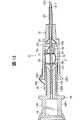
これらの図に示す留置針組立体11は、外針と内針とを備えるもので、特に、輪液用の留置針組立体を構成するものであり、留置針である外針121と、外針121の基端側に設けられた外針ハブ122とで構成されたハブ付き外針12と、外針121内に挿入して使用される内針131と、内針131の基端側に設けられた内針ハブ132とで構成されたハブ付き内針13と、内針131に装着された前記第4実施形態のプロテクタ7Aとを備えている。以下、各部の構成について説明する。
外針121は、中空状をなし、ある程度の可撓性を有するものが好ましく用いられる。外針121の構成材料としては、特に限定されないが、例えば、エチレン−テトラフルオロエチレン共重合体(ETFE)、ポリウレタン、ポリエーテルナイロン樹脂等の各種軟質樹脂が好ましい。
外針121の先端部は、生体への穿刺を容易かつ低侵襲で行うために、外径が先端方向に向かって漸減するテーパ状をなしている。
外針121の基端部には、外針ハブ122が液密に固着され、外針121の内腔と外針ハブ122の内部とが連通している。外針ハブ122は、ほぼ筒状の部材であり、基端方向に向かってその外径および内径が漸増するテーパ状をなしている。
内針(針体)131は、前記第1実施形態における針管4と同様の材料、形状等からなる。
この内針131は、外針121の内腔に挿入された状態、すなわち図12に示す状態で使用される。以下、この状態を「組み立て状態」と言う。
内針131の長さは、組み立て状態としたとき、少なくとも針先1311が外針121の先端開口1211から突出する程度の長さとされる。
内針131の基端部は、内針ハブ132の先端部と固着され、内針131の内腔は、内針ハブ132の内部空間と連通している。
内針ハブ132は、ほぼ円筒状の中空部材で構成されており、本体部1321と、該本体部1321の先端側に設けられ、本体部1321より細径な細径部1322とを有している。
この内針ハブ132は、好ましくは透明(無色透明)、着色透明または半透明の樹脂で構成され、内部の視認性が確保されている。これにより、針先1311が血管を確保した際、内針131を介して流入する血液のフラッシュバックを目視で確認することができる。
また、内針ハブ132の基端部の開口には、該開口を覆うように、気体は透過するが液体は遮断する性質を有する通気フィルタ14が設置されている。
外針ハブ122および内針ハブ132の構成材料は、特に限定されず、各種樹脂材料が使用できる。
プロテクタ7Aは、内針131に装着されており、図12に示すように、組み立て状態においては、外針ハブ122の内部空間に収納されている。
本実施形態の留置針組立体11は、組み立て状態においてプロテクタ7Aと外針ハブ122とを連結する連結手段15を有している。この連結手段15は、円筒状をなす円筒部材(当接部材)151と、該円筒部材151と外針ハブ122とを連結するテープ152とを有している。
円筒部材151は、基端開口を有しており、組み立て状態においては、該基端開口から円筒部材151の内側に内針ハブ132の細径部1322が挿入、遊嵌した状態になっている。
円筒部材151の先端部には、先端壁(底部)1511が設けられている。先端壁1511の中央には、孔が形成されており、内針131は、該孔を貫通している。
組み立て状態においては、円筒部材151の先端側の一部は、外針ハブ122の内側に挿入、遊嵌した状態になっている。また、組み立て状態においては、円筒部材151の先端部(先端壁1511の外面)は、プロテクタ7Aの基端部に当接または近接した状態になっている。
テープ152は、可撓性を有するシート状の部材であり、例えばポリエチレン、ポリプロピレン、ポリエステル、紙、不織布などから構成され、その基端部は、円筒部材151の外面に熱融着または粘着されており、その先端部は、外針ハブ122の外面に熱融着または粘着されている。すなわち、テープ152は、外針ハブ122の基端外周に設けられたフランジ1221をまたぐように設けられている。
テープ152には、プロテクタ7Aと外針ハブ122とが分離するときに破断する破断部として、ミシン目1521がテープ152を横断するように形成されている。
このような構成により、組み立て状態では、外針ハブ122とプロテクタ7Aとは、連結手段15を介して連結されている。
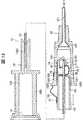
このような連結手段15が設けられていることにより、留置針組立体11の組み立て状態からハブ付き内針13をハブ付き外針12に対し相対的に基端方向に移動すると(ハブ付き内針13の内針131をハブ付き外針12の外針121から引き抜くと)、プロテクタ7Aは、円筒部材151の先端部に当接することにより基端方向への移動が防止され、ハブ付き外針12の方に残存する。すなわち、プロテクタ7Aは、内針131に対しては、第1の姿勢を維持しつつ相対的に先端方向に移動し、内針131の針先1311が針体当接部104を通過すると、該第1の姿勢から、内針131の針先1311を覆う第2の姿勢へと変位する。
プロテクタ7Aは、前述したように、第2の姿勢になると、内針131に対する相対的な移動が禁止(阻止)される。よって、プロテクタ7Aが第2の姿勢となった状態から、さらにハブ付き内針13をハブ付き外針12に対し相対的に基端方向に移動すると、その操作力(引き抜き力)が円筒部材151を介してテープ152に作用し、ミシン目1521が破断する。これにより、プロテクタ7Aは、ハブ付き外針12(外針ハブ122)から分離して、内針131の先端に残存し、その針先1311をガードする(覆う)。
このように、留置針組立体11では、ハブ付き内針13をハブ付き外針12に対し相対的に基端方向に移動する操作のみによって、プロテクタ7Aで内針131の針先1311を覆うことおよびプロテクタ7Aをハブ付き外針12から離反することができ、プロテクタ7Aで内針131の針先1311を覆うための別途の操作が不要である。これにより、内針131の針先1311をプロテクタ7Aで極めて容易かつ確実に覆う(収納する)ことができる。
次に、留置針組立体11の使用方法の一例について、詳細に説明する。
[1] 留置針組立体11を組み立て状態とし、内針ハブ132等を手で把持しつつ、内針131および外針121を患者の血管(静脈または動脈)に穿刺する。
[2] 内針131の針先1311が血管に穿刺されると、血管の内庄(血圧)により血液が内針131内を基端方向へ逆流し、内針ハブ132内に導入され、視認性を有する内針ハブ132を介してこのフラッシュバックを視認することができる。これにより内針131の針先1311が血管を確保したことを知ることができる。
なお、この血液の流入に伴い、内針ハブ132内の空気は、通気フィルタ14を通って排出されるが、血液は、通気フィルタ14を通過できず、外部への漏れ出しは生じない。
[3] さらに内針131および外針121を微小距離先端方向へ進めると、外針121の先端開口1211が血管内に挿入される。これにより、外針121が血管を確保する。
[4] 血管に留置されている外針121を手で押さえつつ、他方の手で内針ハブ132を把持し、基端方向へ引っ張る。これにより、内針131が外針121から抜き取られる。このとき、プロテクタ7Aは、外針ハブ122と連結されていることから、ハブ付き外針12の方に残存する。すなわち、プロテクタ7Aは、内針131に対しては、相対的に先端方向に移動する。
本発明では、前述したようにプロテクタ7Aが針管4に対し円滑に移動可能になっていることから、僅かな操作力で内針131を外針121から抜き取ることができ、この操作を容易、迅速に行うことができる。また、プロテクタ7Aが第2の姿勢になる前に連結手段15による連結が解除されてしまう(ミシン目1521が破断してしまう)ような不都合を防止することもできる。
[5] さらに内針ハブ132を基端方向へ引っ張ると、前述したように、内針131の針先1311が針体当接部104を通過し、針体当接部104によるブレーキ作用留保状態が解除される。これにより、プロテクタ7Aは、弾性的に(自身の弾性により)変形して、図13に示す第2の姿勢となる。
プロテクタ7Aが第2の姿勢となると、第1の部位71のブレーキ作用によって、プロテクタ7Aは、針先1311が第1の孔81を通過する前に内針131に対し停止(静止)する。これにより、プロテクタ7Aは、内針131の長手方向に沿った移動が禁止(阻止)され、内針131の針先1311を覆った(収納した)状態を維持する。
[6] プロテクタ7Aが第2の姿勢となった状態から、さらに内針ハブ132を基端方向に引っ張ると、その引っ張り力が連結手段15に作用し、ミシン目1521が破断する。これにより、プロテクタ7Aは、ハブ付き外針12(外針ハブ122)から分離して、内針131の先端に残存する(図13参照)。
[7] 内針131が抜き取られたハブ付き外針12の外針ハブ122には、輪液セットのコネクタ等(図示せず)を素早く接続し、定法に従い、輪液の投与を開始する。
このようにして外針121から内針131を抜き取った後は、ハブ付き内針13は不要となるため、廃棄処分に供される。
以上説明したように、この留置針組立体11によれば、ハブ付き外針12から取り外されたハブ付き内針13の針先1311がプロテクタ7A内に収納され、特に、針先1311がプロテクタ7Aの先端から突出することや、プロテクタ7Aが内針131から外れてしまうことがないため、廃棄処理を行う者等が針先1311で誤って手指等を刺すという事故が防止される。
図14は、プロテクタの他の構成例を示す図であり、図12のプロテクタ7Aの代わりに、第1実施形態のプロテクタ2Aが使用されている。このように、留置針組立体11は、前記第1実施形態ないし第3実施形態および第5実施形態のプロテクタを備えるものであってもよい。
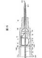
図15は、連結手段の他の構成例を示すための図であり、組み立て状態における外針ハブ付近の縦断面図である。
以下、同図を参照して本発明の留置針組立体における連結手段の他の構成例について説明するが、前述した実施形態との相違点を中心に説明し、同様の事項はその説明を省略する。
本実施形態の留置針組立体における連結手段は、内針131が貫通(挿通)する孔1531を有する円環状(円板状)または略C字形状のリング部材153で構成されている。
このリング部材153の外周部は、組み立て状態においては、外針ハブ122の内側に形成された凹部1222(溝部)に挿入(係止)しており、その先端面は、プロテクタ7Aの基端部に当接または近接している。また、リング部材153は、プロテクタ7Aに基端側から当接し得る当接部材としての機能をも有するものである。
このような組み立て状態からハブ付き内針13をハブ付き外針12に対し相対的に基端方向に移動すると、プロテクタ7Aは、リング部材153の先端面に当接することにより基端方向への移動が防止され、ハブ付き外針12の方に残存する。すなわち、プロテクタ7Aは、内針131に対しては、第1の姿勢を維持しつつ相対的に先端方向に移動し、内針131の針先1311が針体当接部104を通過すると、該第1の姿勢から、内針131の針先1311を覆う第2の姿勢へと変位する。
この状態からさらにハブ付き内針13をハブ付き外針12に対し相対的に基端方向に移動すると、その操作力(引き抜き力)により、リング部材153は、みかけの外径が小さくなるように変形し、凹部1222から外れ、外針ハブ122に対し基端方向に移動する。この移動により、リング部材153の外針ハブ122に対する係止が解除され、プロテクタ7Aは、外針ハブ122から分離して、内針131の先端に残存し、その針先1311をガードする。
以上、本発明のプロテクタおよび留置針組立体を図示の実施形態について説明したが、本発明は、これらに限定されるものではなく、プロテクタおよび留置針組立体を構成する各部は、同様の機能を発揮し得る任意の構成のものと置換することができる。
例えば、前記第1実施形態ないし第3実施形態のプロテクタの本体部は、全体形状としてほぼS字状のものに限らず、例えばほぼ「の」字状のものなどであってもよい。
また、前記第1実施形態ないし第3実施形態のプロテクタについても、プロテクタの本体部が、複数の部品で構成されるようなものであってもよい。例えば、板状のブレーキ部と、該ブレーキ部を針体に対する傾斜角度が小さくなる方向に付勢する付勢部材(バネ)とが別部品で構成されるようなものでもよい。
また、本発明のプロテクタは、各種注射針に限らず、例えば、留置針(外針)と組み合わせて用いる留置針組立体にも装着して使用することができる。
また、本発明の留置針組立体における連結手段は、図示のような構成に限らず、プロテクタが第1の姿勢から第2の姿勢に変位(変形)するまでプロテクタと外針ハブとの連結状態を維持することができるものであれば、いかなるものでもよい。また、そのような連結手段を有しないものであってもよい。
【図面の簡単な説明】
図1は、本発明の第1実施形態のプロテクタを有する穿刺具(注射針)を示す側面図(使用状態)である。
図2は、本発明の第1実施形態のプロテクタを有する穿刺具(注射針)を示す側面図(針先収納状態)である。
図3は、本発明の第2実施形態のプロテクタを有する穿刺具(注射針)を示す側面図(使用状態)である。
図4は、本発明の第2実施形態のプロテクタを有する穿刺具(注射針)を示す側面図(針先収納状態)である。
図5は、本発明の第3実施形態のプロテクタを有する穿刺具(注射針)を示す側面図(使用状態)である。
図6は、本発明の第3実施形態のプロテクタを有する穿刺具(注射針)を示す側面図(針先収納状態)である。
図7は、本発明の第4実施形態のプロテクタを針体に装着した状態を示す断面側面図であり、プロテクタは第1の姿勢で示されている。
図8は、本発明の第4実施形態のプロテクタを針体に装着した状態を示す側面図であり、プロテクタは第1の姿勢で示されている。
図9は、本発明の第4実施形態のプロテクタを針体に装着した状態を示す斜視図であり、プロテクタは第1の姿勢で示されている。
図10は、図7に示すプロテクタを第2の姿勢で示した断面側面図である。
図11は、本発明の第5実施形態のプロテクタを針体に装着した状態を示す断面側面図であり、プロテクタは第2の姿勢で示されている。
図12は、本発明の留置針組立体(組み立て状態)の実施形態を示す縦断面図である。
図13は、図12に示す留置針組立体において、内針ハブを外針ハブに対し相対的に基端方向に移動した状態を示す縦断面図である。
図14は、プロテクタの他の構成例を示すための本発明の留置針組立体の実施形態を示す縦断面図である。
図15は、連結手段の他の構成例を示すための組み立て状態における外針ハブ付近の縦断面図である。Field of the invention
The present invention relates to a protector and an indwelling needle assembly. More specifically, for example, the present invention relates to a needle protector used to puncture a blood vessel or the like at the time of collecting fluid or blood, and an indwelling needle assembly including the same.
Description of conventional technology
For example, when injecting fluid into a patient, an indwelling needle connected to an infusion line is punctured into a patient's blood vessel, and is indwelled. Such an indwelling needle is a hollow outer needle, an outer needle hub fixed to the proximal end of the outer needle, an inner needle inserted into the outer needle, and having a sharp needle tip at the tip, and an inner needle. And an inner needle hub fixed to the proximal end.
When puncturing this indwelling needle into a patient's blood vessel, the inner needle is inserted into the outer needle, and the puncturing operation is performed with the needle tip of the inner needle protruding from the tip of the outer needle. Then, when the needle tip of the inner needle reaches the inside of the blood vessel, the blood flowing from the opening of the needle tip flows through the lumen of the inner needle, and flows into the transparent inner needle hub (flashback). Thereby, it can be confirmed that the inner needle has secured the blood vessel.
When this flashback is confirmed, the inner needle and the outer needle are advanced slightly, and the tip of the outer needle is inserted into the blood vessel. Next, while grasping the outer needle by hand, the inner needle is pulled out from the outer needle, and the connector of the annular fluid line is connected to the outer needle hub. Then, the infusion is administered through the connected infusion line and the outer needle.
By the way, the inner needle pulled out from the outer needle is unnecessary and is provided for disposal.However, if the inner needle is discarded as it is, there is an accident that a discarding worker or the like accidentally points a finger or the like with the tip of the inner needle. May get up. In particular, since blood adheres and remains on the surface and inside of the inner needle, infection may occur due to such a stab.
Therefore, it is preferable that the used inner needle is stored in a hard and strong dedicated container that does not pierce the needle tip and discarded. However, such a dedicated container is always carried and carried to each patient. It is difficult from the point of view of business efficiency, so at present, used inner needles should be discarded in the opened packaging material containing the indwelling needle kit, Measures have been taken, such as putting on a cap and discarding it.
However, even when wrapping the inner needle with a wrapping material or putting a cap on the inner needle, great care must be taken to prevent the operator's hand from being stuck with the needle of the inner needle. However, there is a problem in that disposal of the inner needle after use requires a great deal of trouble.
SUMMARY OF THE INVENTION An object of the present invention is to provide a protector which can store the needle tip of a used needle body by a simple operation and is highly safe in disposal processing and the like, and an indwelling needle assembly provided with the protector. is there.
Summary of the Invention
Such an object is achieved by the present invention described in the following (1) to (25).
(1) A first posture that is relatively movable along the longitudinal direction of the needle body having a sharp needle tip at the tip, and in the longitudinal direction of the needle body while covering the needle tip of the needle body. A protector displaceable to a second position in which relative movement along is prohibited,
It has a plate-shaped brake portion formed with a hole through which the needle body can pass,
In the second posture, the inclination angle of the brake unit with respect to the needle body is smaller than that in the first posture, so that the gap between the inner surface of the hole of the brake unit and the outer peripheral surface of the needle body is reduced. A protector characterized in that a frictional force is generated or increased, thereby prohibiting relative movement of the needle body along a longitudinal direction.
(2) biasing means for biasing the brake unit so that the inclination angle of the brake unit with respect to the needle body is reduced;
When the first attitude, the inclination defining means for defining the inclination of the brake portion with respect to the needle body,
The protector according to the above (1), wherein when the needle is moved to the distal end portion, the regulation by the inclination regulating means is released, whereby the first posture is changed to the second posture.
(3) A first posture which is relatively movable along the longitudinal direction of the needle body having a sharp needle tip at the tip, and in the longitudinal direction of the needle body while covering the needle tip of the needle body. A protector displaceable to a second position in which relative movement along is prohibited,
Having a main body formed by deforming a plate member having elasticity,
A first hole and a second hole through which the needle body can penetrate are formed in the main body, respectively.
On the needle tip side of the main body, a penetrating portion through which the needle body can penetrate is formed,
In the first posture, the needle body penetrates the first hole, the second hole, and the penetrating portion, and moves from the state toward the distal end with respect to the needle body to perform the penetration. When the engagement between the portion and the needle body is released, the plate-like member near the first hole with respect to the needle body is elastically deformed such that the inclination angle becomes smaller than in the first posture. Then, the second posture is established, whereby a frictional force is generated or increased between the inner surface of the first hole and the outer peripheral surface of the needle body, and the relative movement along the longitudinal direction of the needle body is generated. Wherein the protector is configured to be prohibited.
(4) The protector according to (3), wherein the tip of the main body covers the needle tip of the needle body in the second posture.
(5) The main body has a substantially S-shape as a whole, the first hole is formed at the center of the main body, and the second hole is provided at the needle base of the main body. The protector according to (3) or (4), which is formed on the side.
(6) The above-mentioned (3) to (5), further including a lateral displacement prevention member positioned between the penetrating portion and the first hole, for preventing lateral displacement of the needle tip of the needle body in the second posture. The protector according to any of the above.
(7) In any one of the above (3) to (6), further comprising a cap member located between the penetrating portion and the first hole and covering the needle tip of the needle body in the second posture. Protector.
(8) When the distal end portion of the protector is pressed in the proximal direction in the second posture, a force such that the inclination angle becomes smaller with respect to the brake portion or the plate-shaped member near the first hole. The protector according to any one of the above (1) to (7), having means for acting.
(9) In the first posture, the inclination angle of the plate portion in the vicinity of the brake portion or the first hole with respect to the needle body is substantially perpendicular to one of the above (1) to (8). The described protector.
(10) The protector according to any one of (1) to (9), wherein the inner diameter of the first hole (the hole) is larger than the outer diameter of the needle body by 0.01 to 1 mm.
(11) The protector according to any one of the above (1) to (10), wherein the thickness of the brake portion or the plate-like member is 0.05 to 2 mm.
(12) A first posture that is relatively movable along the longitudinal direction of the needle body having a sharp needle tip at the tip, and in the longitudinal direction of the needle body while covering the needle tip of the needle body. A plate-like brake portion, which is displaceable to a second position in which relative movement along the protruding portion is prohibited, the plate-shaped brake portion being made of a metal material and having a hole through which the needle body can pass;
Urging means for urging the brake portion such that the inclination angle of the brake portion with respect to the needle body is reduced;
A resin material that is provided closer to the needle tip than the brake portion and has a function of preventing the inclination angle of the brake portion with respect to the needle body from changing by contacting the needle body in the first posture; And a needle contact portion configured with
From the first posture, the needle body moves toward the distal end relative to the needle body, and the needle body contact portion passes through the needle tip and separates from the needle body, whereby the urging means The angle of inclination of the brake unit with respect to the needle body is deformed to be smaller than that in the first posture to be in the second posture, whereby the friction between the inner surface of the hole and the surface of the needle body is increased. A protector characterized in that a force is generated or increased to prohibit relative movement of the needle body along a longitudinal direction.
(13) The protector according to the above (12), wherein the urging means is a plate-like member continuous from the brake portion, and exerts an urging force by its elastic force.
(14) The protector according to the above (12) or (13), wherein in the first posture, the sliding resistance of the needle body contact portion with respect to the needle body is smaller than the sliding resistance of the brake portion with respect to the needle body. .
(15) The protector according to any one of (12) to (14), further including a needle tip receiving portion that covers the needle tip from the distal end side in the second posture.
(16) A cover portion that covers at least a portion near the needle body contact portion, and the cover portion prevents an operation of moving the portion near the needle body contact portion in the distal direction in the second posture. The protector according to any one of the above (12) to (15), which has a function.
(17) The protector according to any one of the above (12) to (16), wherein a second hole through which the needle body can penetrate is formed closer to a needle than the brake portion.
(18) A cover portion provided continuously from the member near the second hole and covering at least a portion near the needle body contact portion,
When an external force in the proximal direction and / or the distal direction is applied to the cover portion in the second posture, the inclination of the member near the second hole with respect to the needle relative to the member near the second hole. The protector according to the above (17), wherein a force that reduces the angle acts.
(19) The protector according to any one of the above (12) to (18), which covers the needle tip of the needle body from substantially the entire circumference in the second posture.
(20) an inner needle having a sharp needle tip at the tip,
A protector according to any one of (1) to (19), attached to the inner needle;
An inner needle hub installed on the proximal end side of the inner needle,
A hollow outer needle into which the inner needle can be inserted,
An indwelling needle assembly, comprising: an outer needle hub installed on a proximal end side of the outer needle.
(21) The indwelling needle assembly according to the above (20), further comprising a connecting means for connecting the outer needle hub and the protector.
(22) When the inner needle hub is moved in the proximal direction relative to the outer needle hub, the protector is moved in the distal direction relative to the inner needle by the connecting means, so that the first needle is moved. The connected state of the protector and the hub-attached outer needle is maintained until the posture is displaced from the posture to the second posture,
The indwelling needle assembly according to (21), wherein the protector and the outer needle hub are separable after the protector is displaced to the second posture.
(23) The indwelling needle assembly according to the above (21) or (22), wherein the connecting means has a break portion that breaks when the protector and the outer needle hub are separated.
(24) The indwelling needle assembly according to any one of the above (21) to (23), wherein the connecting means has a contact member that comes into contact with the protector from a proximal end side.
ADVANTAGE OF THE INVENTION According to this invention, the needle body after use can be covered with a protector by simple operation quickly and safely, and there is no accident that a finger etc. is accidentally stabbed with a needle point at the time of disposal processing, etc., Thus, a protector and an indwelling needle assembly which are extremely excellent in safety can be provided.
Further, according to the present invention, the above effect can be achieved with a very small protector, and the protector fits in a small space at the base of the needle when in use. Therefore, it is easy to secure a space for installing the protector, and the protector can be mounted on a normal needle having no special structure for use.
Further, the protector of the present invention having the needle body contact portion made of a resin material can move smoothly (with a relatively small operation force) with respect to the needle body in the first posture. Therefore, the operation of covering the needle tip with the protector can be performed quickly, easily and reliably.
When the main body of the protector is formed by deforming a plate-like member, the above-mentioned effect can be achieved with an extremely simple structure.
In addition, when the lateral displacement preventing member is provided, the protrusion of the needle tip can be more reliably prevented even when a strong lateral external force acts on the protector.
In addition, the indwelling needle assembly of the present invention does not require a process (for example, forming a concave portion or a convex portion) for preventing the protector from being detached from the inner needle (needle body). Accordingly, the distal end portion of the inner needle can have a smooth outer peripheral surface, which does not cause a decrease in the strength of the inner needle, an increase in piercing resistance, and the like, and is easy to manufacture.
In the case where the connecting means is provided in the indwelling needle assembly of the present invention, the needle tip of the inner needle can be more reliably covered with the protector with a simpler operation, and safety and operability are further improved. I can do it.
DESCRIPTION OF THE PREFERRED EMBODIMENTS
Hereinafter, a protector of the present invention will be described in detail based on a preferred embodiment shown in the accompanying drawings.
<First Embodiment of Protector>
1 and 2 are side views showing a protector according to the first embodiment of the present invention. In the following description, the needle tip side in FIGS. 1 and 2 is referred to as “tip”, the hub side is referred to as “base end”, and the left side with the tip up is referred to as “one end”, and the right side is referred to as “other end”. I do.
The
The
A
Examples of a method for fixing the
The
The
The constituent material of the
The
The
Further, in the illustrated configuration, a
When the
In the illustrated configuration, in the first posture, the
On the other hand, in a natural state where the
Due to this deformation, in a state where the
Here, the inclination angle of the
In the first posture shown in FIG. 1, the
The inclination defining means in the present embodiment is not limited to the
From such a use state (first posture), the
That is, in the second position, the
Accordingly, the
In such a second posture (the needle tip stored state), the
With such a configuration, in the
In addition, since the
In addition, when the
That is, when a pressing force as indicated by an arrow A in FIG. 2 is applied to the
Even if the
Also, when a pressing force as shown by an arrow B in FIG. 2 is applied to the
The first part inclination angle θ in the first posture is not particularly limited, but is preferably 60 ° or more, and more preferably substantially a right angle as in the present embodiment. Although the preferred size of the inner diameter D of the
Since the first part inclination angle θ and the inner diameter D of the
Note that, in the present invention, the
Further, the shape of the
Although the preferred value of the thickness of the plate-like member (first portion 21) forming the
The constituent material of the plate-like member forming the
Next, an example of a method of using the
First, the
Next, when the collection of the blood or the injection of the drug solution is completed, the
Thereafter, the
Here, in the conventional puncturing operation, after the
When the
When the
When the
<Second embodiment of protector>
3 and 4 are side views each showing a puncture device (injection needle) having a protector according to the second embodiment of the present invention. In the following description, the tip side in FIGS. 3 and 4 is referred to as “tip”, the hub side is referred to as “base end”, and the left side with the tip up is “one end”, and the right side is “other end”. It will be described as.
Hereinafter, a second embodiment of the protector of the present invention will be described with reference to these drawings, but the description will be focused on the differences from the above-described embodiment, and the description of the same items will be omitted.
The
The
The
That is, in the first posture (used state) shown in FIG. 3, the
Then, in the second posture (needle tip storage state) shown in FIG. 4, the
The opening at the tip end of the
With such a configuration, in the
Further, since the
The constituent material of the
When the constituent material of the
<Third embodiment of protector>
5 and 6 are side views each showing a puncture device (injection needle) having a protector according to the third embodiment of the present invention. In the following description, the tip of the needle in FIGS. 5 and 6 is referred to as “distal end”, the hub is referred to as “base end”, and the left side with the tip up is “one end” and the right side is “other end”. It will be described as.
Hereinafter, a third embodiment of the protector of the present invention will be described with reference to these drawings, but the description will focus on differences from the above-described embodiment, and description of similar items will be omitted.
The protector 2C of the present embodiment is the same as the
The puncture device 1C of the present embodiment includes such a protector 2C, a
The
That is, in the first posture (used state) shown in FIG. 5, the
The base end surface of the
Although not shown, the protector 2C is provided with a rotation preventing means for preventing the rotation of the
With such a configuration, in the protector 2C of the present embodiment, the same effect as that of the
Furthermore, in the present embodiment, when a pressing force as shown by an arrow C in FIG. 6 acts on the protector 2C in the second posture, that is, when the distal end of the
That is, the pressing force C is transmitted to the
In the present embodiment, similarly to the second embodiment, the
<Fourth embodiment of protector>
7 and 10 are cross-sectional side views showing a protector according to a fourth embodiment of the present invention, and FIGS. 8 and 9 are a side view and a perspective view, respectively, of the protector shown in FIG. In the following description, in FIGS. 7, 8 and 10, the tip side is the “tip”, the hub side is the “base end”, and the left side when the tip is up is “one end”, and the right side is “ The other end will be described.
In these figures, the
7 to 9, the
On the other hand, in FIG. 10, the
The
As shown in FIG. 7, the protector
That is, in the side view (FIG. 7), the
The
The
That is, the
As shown in FIGS. 8 and 9, each of the
In addition, as shown in FIGS. 7 to 9, in the present embodiment, the
Such a protector body 7 'is made of a metal material. Thereby, in the second posture, the frictional force between the inner surface of the
In the present embodiment, the protector main body 7 'is configured such that its respective parts are integrally formed. However, in the present invention, the protector main body 7' may be configured by two or more components.
A
The
With this configuration, the present flag-shaped
When the
Protruding
The
The edge of the
The
The
The
The resin material constituting the plastic member 10 (the needle contact portion 104) is not particularly limited, but may be any of various types such as polyethylene, polypropylene, polyurethane, polystyrene, polycarbonate, polyester, ABS resin, AS resin, fluororesin, and polyacetal. A resin material may be used.
In the present invention, preferably, at least the
The contact surface of the needle
When using the puncture device (when puncturing a living body or the like), such a
In this first posture, the
In the first posture, the
The
Such displacement (deformation) from the first posture to the second posture is caused by a part of the elasticity (elastic force) of the
That is, in a natural state in which no external force is applied to the
With such a configuration, in a state where the
As shown in FIG. 7, in the first posture, since the needle
Therefore, in the first posture, a gap is formed between the
As described above, the needle
That is, in the first posture, the
As described above, in the first posture, the needle
From the first position, the
In the second position, the
Accordingly, the tip is displaced (rotated) with respect to the
In such a second posture, since the
With such a configuration, when the
First part inclination angle θ in first posture1Is not particularly limited, but is preferably 60 ° or more, and more preferably a substantially right angle as in the present embodiment.
Although the preferred size of the inner diameter D of the
First part inclination angle θ in first posture1When the inner diameter D of the
Note that, in the present invention, the
The shape of the
Further, in the present invention, the portion near the second hole 82 (the contact surface with the needle tube 4) is made of the above-described resin material, or the contact surface with the
Although the preferred value of the thickness of the plate-shaped member (particularly, the first portion 71) forming the protector main body 7 'differs depending on the constituent material thereof, the outer diameter of the
When such a
That is, for example, when a pressing force as shown by an arrow A in FIG. 10 is applied to the tip of the
In addition, even if the
Next, an example of a method of using the
[1] With the
[2] When the collection of blood or the injection of the drug solution is completed, the
[3] Next, the
[4] When the
When the
[5] When the
At this time, as described above, the
<Fifth Embodiment of Protector>
FIG. 11 is a sectional side view showing a protector according to the fifth embodiment of the present invention, and the protector is shown in a second posture.
Hereinafter, a fifth embodiment of the protector of the present invention will be described with reference to the same drawing, but the description will focus on the differences from the above-described fourth embodiment, and description of similar items will be omitted.
The
The
That is, the
The
The
That is, when, for example, a finger or the like applies a pulling force as shown by an arrow B in FIG. 11 to the tip of the plastic member 10 (the portion near the needle body contact portion 104), the tip of the
Unlike such a configuration, when the pulling force B can be applied to the tip of the
On the other hand, in the
Further,
That is, for example, when an external force in the distal direction acts on the
Thereby, a frictional force (a braking force acting on the
The remaining force C is transmitted from the
The inclination angles α and β can be arbitrarily adjusted by appropriately selecting the size of the
For this reason, in the present embodiment, even when an external force in the distal direction acts on the
Note that the
<Embodiment of indwelling needle assembly>
FIGS. 12 and 13 are longitudinal sectional views respectively showing an embodiment of the indwelling needle assembly of the present invention. In the following description, the needle tip side in FIGS. 12 and 13 is referred to as “distal end”, the hub side is referred to as “base end”, and the left side when the tip is up is “one end”, and the right side is “other end”. It will be described as.
Hereinafter, an embodiment of the indwelling needle assembly of the present invention will be described with reference to these drawings, but the description will focus on differences from the above-described embodiment of the protector, and a description of similar items will be omitted.
The indwelling
The
The distal end of the
An
The inner needle (needle body) 131 is made of the same material, shape, and the like as the
The
The length of the
The proximal end of the
The
The
In addition, a
The constituent materials of the
The
The indwelling
The
A distal end wall (bottom) 1511 is provided at the distal end of the
In the assembled state, a part of the distal end side of the
The
A
With such a configuration, the
By providing such a connecting
As described above, when the
As described above, in the
Next, an example of a method of using the
[1] (1) With the
[2] When the
With the inflow of the blood, the air in the
[3] When the
[4] While holding down the
In the present invention, since the
[5] When the
When the
[6] (4) When the
[7] (4) A connector for a ring fluid set or the like (not shown) is quickly connected to the
After the
As described above, according to the
FIG. 14 is a diagram showing another configuration example of the protector. The
FIG. 15 is a view showing another configuration example of the connecting means, and is a longitudinal sectional view near the outer needle hub in an assembled state.
Hereinafter, another configuration example of the connecting means in the indwelling needle assembly of the present invention will be described with reference to the same figure, but the description will focus on the differences from the above-described embodiment, and the description of the same items will be omitted. I do.
The connecting means in the indwelling needle assembly of the present embodiment is constituted by an annular (disk-shaped) or substantially C-shaped
In the assembled state, the outer peripheral portion of the
When the
When the
As described above, the protector and the indwelling needle assembly according to the present invention have been described with reference to the illustrated embodiments. However, the present invention is not limited to these, and the respective parts constituting the protector and the indwelling needle assembly have similar functions. It can be replaced with any configuration that can be exhibited.
For example, the main body of the protector according to the first to third embodiments is not limited to a substantially S-shape as a whole, but may be, for example, a substantially “U” -shape.
Also, the protector of the first to third embodiments may be such that the main body of the protector is composed of a plurality of components. For example, a plate-shaped brake portion and a biasing member (spring) for biasing the brake portion in a direction in which the inclination angle with respect to the needle body decreases may be configured as separate components.
Further, the protector of the present invention is not limited to various types of injection needles, and can be used by being attached to, for example, an indwelling needle assembly used in combination with an indwelling needle (outer needle).
Further, the connecting means in the indwelling needle assembly of the present invention is not limited to the configuration shown in the drawing, and the connecting state between the protector and the outer needle hub until the protector is displaced (deformed) from the first position to the second position. Any material can be used as long as it can maintain. Moreover, the thing which does not have such a connection means may be sufficient.
[Brief description of the drawings]
FIG. 1 is a side view (in use) showing a puncture device (injection needle) having a protector according to the first embodiment of the present invention.
FIG. 2 is a side view (needle stowed state) showing a puncture device (injection needle) having the protector according to the first embodiment of the present invention.
FIG. 3 is a side view (in use) showing a puncture device (injection needle) having a protector according to the second embodiment of the present invention.
FIG. 4 is a side view (needle stowed state) showing a puncture device (injection needle) having a protector according to the second embodiment of the present invention.
FIG. 5 is a side view (in use) showing a puncture device (injection needle) having a protector according to the third embodiment of the present invention.
FIG. 6 is a side view showing a puncture device (injection needle) having a protector according to a third embodiment of the present invention (in a state where a needle tip is stored).
FIG. 7 is a sectional side view showing a state where the protector according to the fourth embodiment of the present invention is mounted on a needle body, and the protector is shown in a first posture.
FIG. 8 is a side view showing a state where the protector according to the fourth embodiment of the present invention is mounted on a needle body, and the protector is shown in a first posture.
FIG. 9 is a perspective view showing a state where the protector according to the fourth embodiment of the present invention is mounted on a needle body, and the protector is shown in a first posture.
FIG. 10 is a sectional side view showing the protector shown in FIG. 7 in a second posture.
FIG. 11 is a sectional side view showing a state where the protector according to the fifth embodiment of the present invention is mounted on a needle body, and the protector is shown in a second posture.
FIG. 12 is a longitudinal sectional view showing an embodiment of the indwelling needle assembly (assembled state) of the present invention.
FIG. 13 is a longitudinal sectional view showing a state in which the inner needle hub is moved in the proximal direction relative to the outer needle hub in the indwelling needle assembly shown in FIG.
FIG. 14 is a longitudinal sectional view showing an embodiment of the indwelling needle assembly of the present invention for showing another configuration example of the protector.
FIG. 15 is a longitudinal sectional view of the vicinity of the outer needle hub in an assembled state for illustrating another configuration example of the connecting means.
【0003】
発明の要約
このような目的は、下記(1)〜(27)の本発明により達成される。
(1) 先端に鋭利な針先を有する針体の長手方向に沿って相対的に移動可能な第1の姿勢と、前記針体の針先を覆った状態で、前記針体の長手方向に沿った相対的な移動が禁止される第2の姿勢とに変位可能なプロテクタであって、
前記針体が貫通可能な孔が形成された板状のブレーキ部を有し、
前記第2の姿勢のとき、前記針体に対する前記ブレーキ部の傾斜角度が前記第1の姿勢のときより小さくなることにより、前記ブレーキ部の孔の内面と前記針体の外周面との間の摩擦力が発生または増大し、これにより前記針体の長手方向に沿った相対的な移動が禁止されるよう構成されていることを特徴とするプロテクタ。
(2) 前記針体に対する前記ブレーキ部の傾斜角度が小さくなるように前記ブレーキ部を付勢する付勢手段と、
前記第1の姿勢のとき、前記針体に対する前記ブレーキ部の傾斜を規定する傾斜規定手段とを有し、
前記針体の先端部まで移動したときに前記傾斜規定手段による規定が解除され、これにより前記第1の姿勢から前記第2の姿勢になるよう構成されている上記(1)に記載のプロテクタ。
(3) 先端に鋭利な針先を有する針体の長手方向に沿って相対的に移動可能な第1の姿勢と、前記針体の針先を覆った状態で、前記針体の長手方向に沿った相対的な移動が禁止される第2の姿勢とに変位可能なプロテクタであって、
弾性を有する板状部材を変形してなる本体部を有し、[0003]
Summary of the Invention Such an object is achieved by the present invention described in the following (1) to (27).
(1) A first posture that is relatively movable along the longitudinal direction of the needle body having a sharp needle tip at the tip, and in the longitudinal direction of the needle body while covering the needle tip of the needle body. A protector displaceable to a second position in which relative movement along is prohibited,
It has a plate-shaped brake portion formed with a hole through which the needle body can pass,
In the second posture, the inclination angle of the brake unit with respect to the needle body is smaller than that in the first posture, so that the gap between the inner surface of the hole of the brake unit and the outer peripheral surface of the needle body is reduced. A protector characterized in that a frictional force is generated or increased, thereby prohibiting relative movement of the needle body along a longitudinal direction.
(2) biasing means for biasing the brake unit so that the inclination angle of the brake unit with respect to the needle body is reduced;
When the first attitude, the inclination defining means for defining the inclination of the brake portion with respect to the needle body,
The protector according to the above (1), wherein when the needle is moved to the distal end portion, the regulation by the inclination regulating means is released, whereby the first posture is changed to the second posture.
(3) A first posture that can relatively move along the longitudinal direction of the needle body having a sharp needle tip at the tip, and in the longitudinal direction of the needle body while covering the needle tip of the needle body. A protector displaceable to a second position in which relative movement along is prohibited,
Having a main body formed by deforming a plate member having elasticity,
【0007】
のプロテクタ。
(19) 前記第2の姿勢において、前記針体の針先をほぼ全周から覆う上記(12)ないし(18)のいずれかに記載のプロテクタ。
(20) 先端に鋭利な針先を有する針体の長手方向に沿って相対的に移動可能な第1の姿勢と、前記針体の針先を覆った状態で、前記針体の長手方向に沿った相対的な移動が禁止される第2の姿勢とに変位可能なプロテクタであって、
弾性を有する板状部材を変形してなる本体部を有し、
前記本体部は、その中央部に、前記針体が貫通可能な第1の孔が形成された第1の部位を有し、
その針元側に、前記針体が貫通可能な前記第2の孔が形成された第2の部位を有し、
その針先側に、前記針体が貫通可能な貫通部が形成された第3の部位を有し、さらに前記第1の部位および第2の部位の端部同士を接続する前方接続部と、前記第1の部位および前記第3の部位の端部同士を接続する後方接続部とを有し、それにより、前記本体部は、全体形状としてほぼS字状をなしており、
前記第1の部位と前記後方接続部との接続部分は、前記第1の部位と前記後方接続部とのなす角度が小さくなる方向に付勢されており、
前記第1の姿勢のとき、前記針体が前記第1の孔、前記第2の孔および前記貫通部を貫通しており、
その状態から前記針体に対して先端方向に移動して前記貫通部と前記針体との係合が解除されることにより、前記第1の部位と前記後方接続部とのなす角度が小さくなり、それにより針体に対する前記第1の部位の傾斜角度が前記第1の姿勢のときより小さくなるように弾性的に変形して前記第2の姿勢となり、これにより前記第1の孔の内面と前記針体の外周面との間の摩擦力が発生または増大して前記針体の長手方向に沿った相対的な移動が禁止されるよう構成されていることを特徴とするプロテクタ。
(21) 先端に鋭利な針先を有する針体の長手方向に沿って相対的に移動可能な第1の姿勢と、前記針体の針先を覆った状態で、前記針体の長手方向に沿った相対的な移動が禁止される第2の姿勢とに変位可能なプロテクタであって、
金属材料で構成された板状体を、を変形してなり、
前記針体が貫通可能な第1の孔が形成された第1の部位と、前記第1の部位より針元側に位置し、前記針体が貫通可能な第2の孔が形成された第2の部位と、前記第1の部位および前記第2の部位を端部同士を接続する第3の部位と、を有しており、全体として略「コ」形状をなすプロテクタ本体と、
前記第1の部位と前記第3の部位との接続部分における前記第1の部位と前記第3の部位とのなす角度が小さくなり、それにより前記針体に対する傾斜角度が小さくなるように前記第1の部位を付勢する付勢手段と、
前記第1の部位より針先側に設けられ、前記第1の姿勢のとき前記針体に当接することにより前記第1の部位の前記針体に対する傾斜角度が変化することを防止する機能を有し、樹脂材料で構成された針体当接部とを備えており、
前記第1の姿勢のとき、前記針体が前記第1の孔および前記第2の孔を貫通しており、
前記第1の姿勢から、前記針体に対して相対的に先端方向に移動し、前記針体当接部が前記針先を通過して前記針体から離反することにより、前記付勢手段によって前記第1の部位と前記第3の部位とのなす角度が小さくなり、それにより前記針体に対する前記第1の部位の傾斜角度が前記第1の姿勢のときより小さくなるように変形して前記第2の姿勢となり、これにより前記孔の内面と前記針体の表面との間の摩擦力が発生または増大して前記針体の長手方向に沿った相対的な移動が禁止されるよう構成されていることを特徴とするプロテクタ。
(22) 前記第2の姿勢において、前記針先を先端側から覆う針先受け部を有する上記(21)に記載のプロテクタ。
(23) 先端に鋭利な針先を有する内針と、
前記内針に装着された上記(1)ないし(22)のいずれかに記載のプロテクタと、
前記内針の基端側に設置された内針ハブと、
前記内針が挿入可能な中空の外針と、
前記外針の基端側に設置された外針ハブとを備えることを特徴とする留置針組立体。
(24) 前記外針ハブと前記プロテクタとを連結する連結手段を有する上記[0007]
Protector.
(19) The protector according to any one of (12) to (18), wherein the protector covers the needle tip of the needle body from substantially the entire circumference in the second posture.
(20) A first posture which is relatively movable along the longitudinal direction of the needle body having a sharp needle tip at the tip, and in the longitudinal direction of the needle body with the needle tip of the needle body covered. A protector displaceable to a second position in which relative movement along is prohibited,
Having a main body formed by deforming a plate member having elasticity,
The main body has a first portion in a central portion thereof, in which a first hole through which the needle body can pass is formed.
On the needle base side, there is a second portion in which the second hole through which the needle body can pass is formed,
On the needle tip side, there is provided a third portion formed with a penetrating portion through which the needle body can penetrate, and further, a front connecting portion connecting end portions of the first portion and the second portion, A rear connection portion that connects ends of the first portion and the third portion to each other, whereby the main body portion has an almost S-shape as a whole.
A connection portion between the first portion and the rear connection portion is urged in a direction in which an angle between the first portion and the rear connection portion is reduced,
In the first posture, the needle body passes through the first hole, the second hole, and the penetrating portion,
From this state, the needle moves in the distal direction with respect to the needle body, and the engagement between the penetrating portion and the needle body is released, so that the angle formed between the first portion and the rear connection portion decreases. Accordingly, the first portion is elastically deformed so that the inclination angle of the first portion with respect to the needle body is smaller than that in the first posture, and the second portion is brought into the second posture. A protector characterized in that a frictional force between the needle body and the outer peripheral surface is generated or increased, and relative movement of the needle body along a longitudinal direction is prohibited.
(21) A first posture that can relatively move along the longitudinal direction of the needle body having a sharp needle tip at the tip, and in a longitudinal direction of the needle body while covering the needle tip of the needle body. A protector displaceable to a second position in which relative movement along is prohibited,
By deforming a plate made of metal material,
A first portion in which a first hole through which the needle body can pass is formed; and a first portion in which a second hole which is located closer to the needle than the first portion and through which the needle body can pass is formed. 2, a protector body having a substantially "U" shape as a whole, including a third portion connecting end portions of the first portion and the second portion.
The angle between the first part and the third part in the connecting part between the first part and the third part is reduced, and the angle of inclination with respect to the needle body is thereby reduced. Urging means for urging the first part;
A function is provided on the needle tip side of the first part to prevent the inclination angle of the first part with respect to the needle body from changing by contacting the needle body in the first posture. And a needle contact portion made of a resin material,
In the first posture, the needle body penetrates the first hole and the second hole,
From the first posture, the needle body moves toward the distal end relative to the needle body, and the needle body contact portion passes through the needle tip and separates from the needle body, whereby the urging means The angle formed between the first portion and the third portion is reduced, whereby the inclination angle of the first portion with respect to the needle body is changed so as to be smaller than that in the first posture, and A second posture, whereby a frictional force is generated or increased between the inner surface of the hole and the surface of the needle body, and relative movement of the needle body along the longitudinal direction is prohibited. A protector characterized by having.
(22) The protector according to (21), further including a needle tip receiving portion that covers the needle tip from the distal end side in the second posture.
(23) an inner needle having a sharp needle tip at the tip,
A protector according to any one of the above (1) to (22) attached to the inner needle;
An inner needle hub installed on the proximal end side of the inner needle,
A hollow outer needle into which the inner needle can be inserted,
An indwelling needle assembly, comprising: an outer needle hub installed on a proximal end side of the outer needle.
(24) The above-mentioned having a connecting means for connecting the outer needle hub and the protector.
【0008】
(23)に記載の留置針組立体。
(25) 前記内針ハブを前記外針ハブに対し相対的に基端方向に移動すると、前記連結手段により、前記プロテクタが前記内針に対して相対的に先端方向に移動して前記第1の姿勢から前記第2の姿勢に変位するまで前記プロテクタと前記ハブ付き外針との連結状態が維持され、
前記プロテクタが前記第2の姿勢に変位した後、前記プロテクタと前記外針ハブとが分離可能である上記(24)に記載の留置針組立体。
(26) 前記連結手段は、前記プロテクタと前記外針ハブとが分離するときに破断する破断部を有する上記(24)または(25)に記載の留置針組立体。
(27) 前記連結手段は、前記プロテクタに基端側から当接する当接部材を有する上記(24)ないし(26)のいずれかに記載の留置針組立体。
本発明によれば、簡単な操作で、迅速かつ安全に、使用後の針体をプロテクタで覆うことができ、廃棄処理等に際し、誤って針先で手指等を刺すという事故がなく、衛生面、安全面で極めて優れたプロテクタおよび留置針組立体を提供することができる。
また、本発明によれば、極めて小型のプロテクタで上記効果を達成することができ、プロテクタは、使用状態では針元部の僅かなスペースに収まる。このため、プロテクタ設置スペースの確保が容易で、特別な構造を持たない通常の針体に装着して使用することができる。
また、樹脂材料で構成された針体当接部を有する本発明のプロテクタは、第1の姿勢において針体に対し円滑に(比較的小さい操作力で)移動可能で ある。よって、プロテクタで針先を覆う操作を迅速、容易かつ確実に行うことができる。
また、プロテクタの本体部を板状部材を変形して形成した場合には、極めて簡単な構造で上記効果を達成することができる。
また、横ずれ防止部材を有する場合には、プロテクタに対し強い横方向の外力が作用したような場合にも、針先の突出をより確実に防止することができる。
また、本発明の留置針組立体では、内針(針体)に対しプロテクタが離脱するのを防止するための加工(凹部や凸部を形成するなど)が不要である。これにより、内針の先端部を円滑な外周面を有するものとすることができ、内針の強度の低下や刺通抵抗の増大等を招くことがないとともに、製造が容易である。
また、本発明の留置針組立体において連結手段を設けた場合には、より簡単な[0008]
The indwelling needle assembly according to (23).
(25) When the inner needle hub is moved in the proximal direction relative to the outer needle hub, the protector is moved in the distal direction relative to the inner needle by the connecting means, and the first needle is moved. The connected state between the protector and the outer needle with hub is maintained until the posture is shifted from the posture to the second posture,
The indwelling needle assembly according to (24), wherein the protector and the outer needle hub are separable after the protector is displaced to the second posture.
(26) The indwelling needle assembly according to the above (24) or (25), wherein the connecting means has a break portion that breaks when the protector and the outer needle hub are separated.
(27) The indwelling needle assembly according to any one of (24) to (26), wherein the connection unit has a contact member that contacts the protector from a proximal end side.
ADVANTAGE OF THE INVENTION According to this invention, the needle body after use can be covered with a protector by simple operation quickly and safely, and there is no accident that a finger etc. is accidentally stabbed with a needle point at the time of disposal processing, etc., Thus, a protector and an indwelling needle assembly which are extremely excellent in safety can be provided.
Further, according to the present invention, the above effect can be achieved with a very small protector, and the protector fits in a small space at the base of the needle when in use. Therefore, it is easy to secure a space for installing the protector, and the protector can be mounted on a normal needle having no special structure for use.
Further, the protector of the present invention having the needle body contact portion made of a resin material can move smoothly (with a relatively small operation force) with respect to the needle body in the first posture. Therefore, the operation of covering the needle tip with the protector can be performed quickly, easily and reliably.
When the main body of the protector is formed by deforming a plate-like member, the above-mentioned effect can be achieved with an extremely simple structure.
In addition, when the lateral displacement preventing member is provided, the protrusion of the needle tip can be more reliably prevented even when a strong lateral external force acts on the protector.
In addition, the indwelling needle assembly of the present invention does not require a process (for example, forming a concave portion or a convex portion) for preventing the protector from being detached from the inner needle (needle body). Accordingly, the distal end portion of the inner needle can have a smooth outer peripheral surface, which does not cause a decrease in the strength of the inner needle, an increase in piercing resistance, and the like, and is easy to manufacture.
In the case where the connecting means is provided in the indwelling needle assembly of the present invention, a simpler
【0013】
第3の部位23は、それぞれ針管4に対しほぼ垂直になっており、後方接続部24および前方接続部25は、それぞれ針管4とほぼ平行になっている。これにより、第1の姿勢において第1の部位21と後方接続部24とのなす角度は、ほぼ直角になっている。
これに対し、プロテクタ2Aが針管4に装着されず外力がかかっていない自然状態(外力を付与しない状態)においては、第1の部位21と後方接続部24とのなす角度は、図2に示す状態よりも小さく設定されている。すなわち、プロテクタ2Aは、第1の部位21と後方接続部24とが開くように変形(弾性変形)させられた状態で、針管4に装着されている。
この変形により、プロテクタ2Aが針管4に装着された状態では、第1の部位21と後方接続部24との接続部分は、第1の部位21と後方接続部24とのなす角度が小さくなる方向に付勢されており、第1の部位21と第3の部位第1の部位21は、針管4に対する傾斜角度(図1中のθおよび図2中のθ’で示す角度)が小さくなるような方向に付勢されている。換言すれば、プロテクタ2Aにおける第1の部位21と後方接続部24との間の部分は、その弾性によって第1の部位21の針管4に対する傾斜角度が小さくなるような方向に第1の部位21を付勢する付勢手段となっている。
ここで、第1の部位21の針管4に対する傾斜角度は、第1の部位21と針管4とがなす角のどちら側を選択するかによって2つの大きさで表すことができるが、本明細書において「第1の部位21の針管4に対する傾斜角度」とは、後述する第2の姿勢のときに90°未満になる角(小さい方の角)の角度を指すものとする。すなわち、本実施形態においては、図1中のθおよび図2中のθ’で示す角度である。この角度を以下、「第1の部位傾斜角度」と言う。
図1に示す第1の姿勢においては、第3の部位23に形成された第3の孔33[0013]
The
On the other hand, in a natural state where the
Due to this deformation, when the
Here, the inclination angle of the
In the first posture shown in FIG. 1, the
【0029】
通し、さらに、針先収納空間9および切欠き部106を通過してプロテクタ7Aの先端から突出する。
また、第1の姿勢のとき、第1の部位71と、第2の部位72とは、それぞれ、針管4に対しほぼ垂直な姿勢になっている。
プロテクタ7Aは、このような第1の姿勢から図10に示す第2の姿勢に変位(変形)して、針先41を覆うことができる。この第2の姿勢においては、プロテクタ本体7’における第1の部位71と第3の部位73とのなす角度が第1の姿勢のときよりも小さくなる。すなわち、プロテクタ7Aは、第1の部位71と第3の部位73とが閉じるように(第1の部位71が第3の部位73に近づくように)変形することにより、第1の姿勢から第2の姿勢に変位(変形)する。
このような第1の姿勢から第2の姿勢への変位(変形)は、プロテクタ本体7’における第1の部位71と第3の部位73との一部の弾性(弾性力)によって生じるようになっている。
すなわち、プロテクタ7Aに外力を付与しない自然状態(プロテクタ7Aを針管4に装着していない状態)においては、第1の部位71と第3の部位73とのなす角度は、図10に示す状態よりもさらに小さくなっており、プロテクタ7Aは、このような自然状態から第1の部位71と第3の部位73とが開くように(第1の部位71が第3の部位73から遠ざかるように)変形(弾性変形)した状態とされて針管4に装着されている。
このような構成により、プロテクタ7Aが針管4に装着された状態では、第1の部位71と第3の部位73との接続部分において第1の部位1と第3の部位73とのなす角度が小さくなる方向に付勢されており、第1の部位71は、針管4に対する傾斜角度(図8中のθ1および図10中のθ1’で示す角度)が小さくなるような方向に付勢されている。すなわち、プロテクタ[0029]
Then, it passes through the needle
In the first posture, the
The
Such displacement (deformation) from the first posture to the second posture is caused by a part of the elasticity (elastic force) of the
That is, in a natural state in which no external force is applied to the
With such a configuration, when the
Claims (12)
Translated fromJapanese前記針体が貫通可能な孔が形成された板状のブレーキ部を有し、
前記第2の姿勢のとき、前記針体に対する前記ブレーキ部の傾斜角度が前記第1の姿勢のときより小さくなることにより、前記ブレーキ部の孔の内面と前記針体の外周面との間の摩擦力が発生または増大し、これにより前記針体の長手方向に沿った相対的な移動が禁止されるよう構成されていることを特徴とするプロテクタ。A first position that is relatively movable along the longitudinal direction of the needle body having a sharp needle tip at the tip, and a relative position along the longitudinal direction of the needle body with the needle body covered with the needle tip. A protector that can be displaced to a second position in which a temporary movement is prohibited,
It has a plate-shaped brake portion formed with a hole through which the needle body can pass,
In the second posture, the inclination angle of the brake unit with respect to the needle body is smaller than that in the first posture, so that the gap between the inner surface of the hole of the brake unit and the outer peripheral surface of the needle body is reduced. A protector characterized in that a frictional force is generated or increased, thereby prohibiting relative movement of the needle body along a longitudinal direction.
前記第1の姿勢のとき、前記針体に対する前記ブレーキ部の傾斜を規定する傾斜規定手段とを有し、
前記針体の先端部まで移動したときに前記傾斜規定手段による規定が解除され、これにより前記第1の姿勢から前記第2の姿勢になるよう構成されている請求の範囲第1項に記載のプロテクタ。Urging means for urging the brake unit such that the inclination angle of the brake unit with respect to the needle body is reduced,
When the first attitude, the inclination defining means for defining the inclination of the brake portion with respect to the needle body,
2. The structure according to claim 1, wherein the regulation by the inclination regulating means is released when the needle is moved to the distal end of the needle body, whereby the first posture is changed to the second posture. Protector.
弾性を有する板状部材を変形してなる本体部を有し、
前記本体部に、前記針体が貫通可能な第1の孔および第2の孔がそれぞれ形成されており、
前記本体部の針先側に、前記針体が貫通可能な貫通部が形成されており、
前記第1の姿勢のとき、前記針体が前記第1の孔、前記第2の孔および前記貫通部を貫通しており、その状態から前記針体に対して先端方向に移動して前記貫通部と前記針体との係合が解除されることにより、前記針体に対する前記第1の孔近傍の板状部材の傾斜角度が前記第1の姿勢のときより小さくなるように弾性的に変形して前記第2の姿勢となり、これにより前記第1の孔の内面と前記針体の外周面との間の摩擦力が発生または増大して前記針体の長手方向に沿った相対的な移動が禁止されるよう構成されていることを特徴とするプロテクタ。A first position that is relatively movable along the longitudinal direction of the needle body having a sharp needle tip at the tip, and a relative position along the longitudinal direction of the needle body with the needle body covered with the needle tip. A protector that can be displaced to a second position in which a temporary movement is prohibited,
Having a main body formed by deforming a plate member having elasticity,
A first hole and a second hole through which the needle body can penetrate are formed in the main body, respectively.
On the needle tip side of the main body, a penetrating portion through which the needle body can penetrate is formed,
In the first posture, the needle body penetrates the first hole, the second hole, and the penetrating portion, and moves from the state toward the distal end with respect to the needle body to perform the penetration. When the engagement between the portion and the needle body is released, the plate-like member near the first hole with respect to the needle body is elastically deformed such that the inclination angle becomes smaller than in the first posture. Then, the second posture is established, whereby a frictional force is generated or increased between the inner surface of the first hole and the outer peripheral surface of the needle body, and the relative movement along the longitudinal direction of the needle body is generated. Wherein the protector is configured to be prohibited.
金属材料で構成され、前記針体が貫通可能な孔が形成された板状のブレーキ部と、
前記ブレーキ部の前記針体に対する傾斜角度が小さくなるように前記ブレーキ部を付勢する付勢手段と、
前記ブレーキ部より針先側に設けられ、前記第1の姿勢のとき前記針体に当接することにより前記ブレーキ部の前記針体に対する傾斜角度が変化することを防止する機能を有し、樹脂材料で構成された針体当接部とを備え、
前記第1の姿勢から、前記針体に対して相対的に先端方向に移動し、前記針体当接部が前記針先を通過して前記針体から離反することにより、前記付勢手段によって前記針体に対する前記ブレーキ部の傾斜角度が前記第1の姿勢のときより小さくなるように変形して前記第2の姿勢となり、これにより前記孔の内面と前記針体の表面との間の摩擦力が発生または増大して前記針体の長手方向に沿った相対的な移動が禁止されるよう構成されていることを特徴とするプロテクタ。A first position that is relatively movable along the longitudinal direction of the needle body having a sharp needle tip at the tip, and a relative position along the longitudinal direction of the needle body with the needle body covered with the needle tip. A protector that can be displaced to a second position in which a temporary movement is prohibited,
A plate-shaped brake portion formed of a metal material and formed with a hole through which the needle body can pass,
Urging means for urging the brake portion such that the inclination angle of the brake portion with respect to the needle body is reduced;
A resin material that is provided closer to the needle tip than the brake portion and has a function of preventing the inclination angle of the brake portion with respect to the needle body from changing by contacting the needle body in the first posture; And a needle contact portion configured with
From the first posture, the needle body moves toward the distal end relative to the needle body, and the needle body contact portion passes through the needle tip and separates from the needle body, whereby the urging means The angle of inclination of the brake unit with respect to the needle body is deformed to be smaller than that in the first posture to be in the second posture, whereby the friction between the inner surface of the hole and the surface of the needle body is increased. A protector characterized in that a force is generated or increased to prohibit relative movement of the needle body along a longitudinal direction.
前記内針に装着された請求項1ないし11のいずれかに記載のプロテクタと、
前記内針の基端側に設置された内針ハブと、
前記内針が挿入可能な中空の外針と、
前記外針の基端側に設置された外針ハブとを備えることを特徴とする留置針組立体。An inner needle having a sharp needle tip at the tip,
A protector according to any one of claims 1 to 11 attached to the inner needle,
An inner needle hub installed on the proximal end side of the inner needle,
A hollow outer needle into which the inner needle can be inserted,
An indwelling needle assembly, comprising: an outer needle hub installed on a proximal end side of the outer needle.
Applications Claiming Priority (5)
| Application Number | Priority Date | Filing Date | Title |
|---|---|---|---|
| JP2000384370 | 2000-12-18 | ||
| JP2000384370 | 2000-12-18 | ||
| JP2001097558 | 2001-03-29 | ||
| JP2001097558 | 2001-03-29 | ||
| PCT/JP2001/010625WO2002049696A1 (en) | 2000-12-18 | 2001-12-05 | Protector and storage needle assembly |
Publications (2)
| Publication Number | Publication Date |
|---|---|
| JPWO2002049696A1true JPWO2002049696A1 (en) | 2004-04-15 |
| JP4252799B2 JP4252799B2 (en) | 2009-04-08 |
Family
ID=26606043
Family Applications (1)
| Application Number | Title | Priority Date | Filing Date |
|---|---|---|---|
| JP2002551033AExpired - Fee RelatedJP4252799B2 (en) | 2000-12-18 | 2001-12-05 | Protector and indwelling needle assembly |
Country Status (7)
| Country | Link |
|---|---|
| US (1) | US7247148B2 (en) |
| EP (1) | EP1344544A4 (en) |
| JP (1) | JP4252799B2 (en) |
| KR (1) | KR100787691B1 (en) |
| CN (1) | CN1276781C (en) |
| AU (2) | AU2105402A (en) |
| WO (1) | WO2002049696A1 (en) |
Families Citing this family (60)
| Publication number | Priority date | Publication date | Assignee | Title |
|---|---|---|---|---|
| US7004927B2 (en)* | 2001-03-15 | 2006-02-28 | Specialized Health Products, Inc. | Safety shield for medical needles |
| US7413562B2 (en) | 2001-03-15 | 2008-08-19 | Specialized Health Products, Inc. | Safety shield for medical needles |
| US6902546B2 (en) | 2001-03-15 | 2005-06-07 | Specialized Health Products, Inc. | Safety shield for medical needles |
| EP2298405B1 (en) | 2002-06-20 | 2020-05-27 | Becton, Dickinson and Company | Catheter and introducer needle assembly with needle shield |
| ES2697329T3 (en)* | 2002-06-20 | 2019-01-23 | Becton Dickinson Co | Apparatus to protect the tip of a catheter introducer needle |
| JP2004073403A (en)* | 2002-08-14 | 2004-03-11 | Terumo Corp | Indwelling needle assembly |
| JP2004113394A (en)* | 2002-09-25 | 2004-04-15 | Terumo Corp | Protector |
| JP2004113524A (en)* | 2002-09-26 | 2004-04-15 | Terumo Corp | Protector |
| JP2004113523A (en)* | 2002-09-26 | 2004-04-15 | Terumo Corp | Protector |
| US7458954B2 (en) | 2002-11-07 | 2008-12-02 | Specialized Health Products, Inc. | Safety shield for medical needles |
| US20050075609A1 (en)* | 2003-10-01 | 2005-04-07 | Latona Patrick C. | Protective needle clips |
| AU2005281261B2 (en)* | 2004-09-03 | 2010-06-17 | Terumo Kabushiki Kaisha | Indwelling needle assembly |
| US7905857B2 (en) | 2005-07-11 | 2011-03-15 | Covidien Ag | Needle assembly including obturator with safety reset |
| US7850650B2 (en) | 2005-07-11 | 2010-12-14 | Covidien Ag | Needle safety shield with reset |
| US7828773B2 (en) | 2005-07-11 | 2010-11-09 | Covidien Ag | Safety reset key and needle assembly |
| CA2599945C (en)* | 2005-03-07 | 2011-07-12 | Erskine Medical Llc | Catheter introducer with needle shield |
| US20060276747A1 (en) | 2005-06-06 | 2006-12-07 | Sherwood Services Ag | Needle assembly with removable depth stop |
| US7731692B2 (en) | 2005-07-11 | 2010-06-08 | Covidien Ag | Device for shielding a sharp tip of a cannula and method of using the same |
| US7654735B2 (en) | 2005-11-03 | 2010-02-02 | Covidien Ag | Electronic thermometer |
| EP2018883A4 (en)* | 2006-05-17 | 2009-05-13 | Terumo Corp | Indwelling needle assembly |
| US8382718B2 (en)* | 2006-07-31 | 2013-02-26 | B. Braun Melsungen Ag | Needle assembly and components thereof |
| JP4994775B2 (en) | 2006-10-12 | 2012-08-08 | 日本コヴィディエン株式会社 | Needle point protector |
| US8357104B2 (en) | 2007-11-01 | 2013-01-22 | Coviden Lp | Active stylet safety shield |
| WO2009067646A1 (en)* | 2007-11-21 | 2009-05-28 | Becton, Dickinson And Company | Needle safety device |
| MX2010005610A (en) | 2007-11-21 | 2010-06-01 | Becton Dickinson Co | Safety needle guard. |
| AU2013263723B2 (en)* | 2007-11-21 | 2016-01-14 | Becton, Dickinson And Company | Needle safety device |
| US20100114067A1 (en)* | 2008-10-31 | 2010-05-06 | Warsaw Orthopedic, Inc. | Multi-Chamber Mixing System |
| CH700159B1 (en)* | 2008-12-30 | 2013-05-31 | Tripomed S R L | Protective device for August |
| SE534021C2 (en)* | 2009-08-13 | 2011-04-05 | Vigmed Ab | Protective device for a catheter needle tip |
| JP5148590B2 (en)* | 2009-12-24 | 2013-02-20 | 株式会社若本製作所 | Lattice structure, method for manufacturing the same, fence, groove cover |
| ES2721902T5 (en) | 2010-09-23 | 2023-06-28 | Greiner Bio One Gmbh | Needle tip protection device |
| MY161281A (en) | 2010-12-02 | 2017-04-14 | Erskine Medical Llc | Needle shield assembly with hub engagement member for needle device |
| ES2725777T3 (en) | 2010-12-02 | 2019-09-27 | Erskine Medical Llc | Release mechanism for use with needle protection devices |
| US8764711B2 (en)* | 2011-02-28 | 2014-07-01 | Injectimed, Inc. | Needle guard |
| AU2015200294B2 (en)* | 2011-02-28 | 2017-02-09 | Injectimed, Inc. | Needle guard |
| US9238104B2 (en) | 2011-02-28 | 2016-01-19 | Injectimed, Inc. | Needle guard |
| WO2012139034A1 (en) | 2011-04-07 | 2012-10-11 | Erskine Medical Llc | Needle shielding device |
| ES2662356T3 (en)* | 2011-04-27 | 2018-04-06 | Kpr U.S., Llc | Safety IV catheter assemblies |
| US8591467B2 (en) | 2011-07-25 | 2013-11-26 | Covidien Lp | Vascular access assembly and safety device |
| CN102698340B (en)* | 2011-09-13 | 2013-08-07 | 张焕娥 | Disposable transfusion needle |
| WO2013048975A1 (en) | 2011-09-26 | 2013-04-04 | Covidien Lp | Safety catheter |
| US8834422B2 (en) | 2011-10-14 | 2014-09-16 | Covidien Lp | Vascular access assembly and safety device |
| CA2854003C (en) | 2011-11-07 | 2020-07-14 | Safety Syringes, Inc. | Contact trigger release needle guard |
| CN102641529B (en)* | 2012-05-08 | 2014-04-16 | 江苏苏云医疗器材有限公司 | Indwelling needle |
| CN102641528A (en)* | 2012-05-08 | 2012-08-22 | 江苏苏云医疗器材有限公司 | Safety remaining needle |
| MX2015002672A (en)* | 2012-08-27 | 2015-10-14 | Injectimed Inc | Needle guard. |
| US10357635B2 (en) | 2013-03-12 | 2019-07-23 | Teleflex Medical Incorporated | Catheter insertion device |
| US11224724B2 (en) | 2013-03-12 | 2022-01-18 | Teleflex Medical Incorporated | Catheter insertion device |
| US9717886B2 (en) | 2013-03-12 | 2017-08-01 | Teleflex Medical Incorporated | Safety clip for a needle |
| GB2508570C2 (en) | 2013-08-21 | 2025-07-30 | Braun Melsungen Ag | Catheter assembly |
| CN103736170A (en)* | 2013-10-12 | 2014-04-23 | 苏州市雅思精密模具有限公司 | Anti-puncture remaining needle |
| AU2016329461B2 (en)* | 2015-09-29 | 2018-08-02 | Terumo Kabushiki Kaisha | Medical elongated body |
| EP3370809A1 (en)* | 2015-11-05 | 2018-09-12 | TSK Laboratory Europe B.V. | Method for connecting two objects using a polymer composition and a system, for use in a cosmetic procedure |
| EP3275484A1 (en) | 2016-07-26 | 2018-01-31 | Delta Med S.p.A. | Protective element for medical needle assemblies |
| US10183124B2 (en)* | 2016-10-12 | 2019-01-22 | Repro-Med Systems, Inc. | System and method for ergonomic needle protector |
| EP4480525A3 (en) | 2017-04-13 | 2025-04-09 | Teleflex Medical Incorporated | Catheter insertion device |
| CN107115109B (en)* | 2017-05-26 | 2018-10-19 | 徐州医科大学 | Protection type arterial puncture detaining needle |
| CN107789704A (en)* | 2017-11-27 | 2018-03-13 | 昆山伊诺特精密部件有限公司 | A kind of safe clip assembly of remaining needle |
| CN113456987B (en)* | 2021-05-31 | 2023-08-08 | 泰尔茂医疗产品(杭州)有限公司 | Introducer protection device, cannula part, cannula assembly and cannula device |
| CN116407186B (en)* | 2023-05-31 | 2023-08-15 | 瀚芯医疗科技(深圳)有限公司 | Puncture locking device and suture equipment |
Family Cites Families (7)
| Publication number | Priority date | Publication date | Assignee | Title |
|---|---|---|---|---|
| ES2081973T3 (en)* | 1989-02-01 | 1996-03-16 | Sero Guard Corp | AUTOMATIC DISPOSABLE HYPODERMIC NEEDLE PROTECTOR. |
| US5601532A (en) | 1993-07-20 | 1997-02-11 | Graphic Controls Corporation | Locking safety cover for sharp instruments |
| GB2292525B (en)* | 1994-08-24 | 1998-07-01 | Sterimatic Holdings Ltd | Catheter placement units |
| US5882337A (en)* | 1995-06-07 | 1999-03-16 | Johnson & Johnson Medical, Inc. | Tip protection device |
| US6012213A (en)* | 1995-06-07 | 2000-01-11 | Chang; Joseph J. | Method for forming a rib on a cannula for a tip protection device |
| US6117108A (en) | 1997-08-20 | 2000-09-12 | Braun Melsungen Ag | Spring clip safety IV catheter |
| US20040049155A1 (en)* | 2002-06-06 | 2004-03-11 | Schramm John B. | Needle tip protector |
- 2001
- 2001-12-05EPEP01271235Apatent/EP1344544A4/ennot_activeWithdrawn
- 2001-12-05WOPCT/JP2001/010625patent/WO2002049696A1/enactiveApplication Filing
- 2001-12-05AUAU2105402Apatent/AU2105402A/enactivePending
- 2001-12-05KRKR1020037008072Apatent/KR100787691B1/ennot_activeExpired - Fee Related
- 2001-12-05USUS10/450,809patent/US7247148B2/ennot_activeExpired - Fee Related
- 2001-12-05AUAU2002221054Apatent/AU2002221054B2/ennot_activeCeased
- 2001-12-05JPJP2002551033Apatent/JP4252799B2/ennot_activeExpired - Fee Related
- 2001-12-05CNCNB018208290Apatent/CN1276781C/ennot_activeExpired - Fee Related
Also Published As
| Publication number | Publication date |
|---|---|
| CN1276781C (en) | 2006-09-27 |
| US20040049163A1 (en) | 2004-03-11 |
| AU2002221054B2 (en) | 2006-08-17 |
| JP4252799B2 (en) | 2009-04-08 |
| EP1344544A1 (en) | 2003-09-17 |
| KR20030070587A (en) | 2003-08-30 |
| WO2002049696A1 (en) | 2002-06-27 |
| CN1501822A (en) | 2004-06-02 |
| EP1344544A4 (en) | 2008-09-03 |
| AU2105402A (en) | 2002-07-01 |
| US7247148B2 (en) | 2007-07-24 |
| KR100787691B1 (en) | 2007-12-21 |
Similar Documents
| Publication | Publication Date | Title |
|---|---|---|
| JP4252799B2 (en) | Protector and indwelling needle assembly | |
| JP5096322B2 (en) | Protector | |
| EP1142603B1 (en) | Indwelling needle assembly | |
| JP5253385B2 (en) | Indwelling needle assembly | |
| US8192404B2 (en) | Indwelling needle assembly | |
| WO2009123025A1 (en) | Indwelling needle assembly | |
| WO2006027923A1 (en) | Indwelling needle assembly | |
| JP2002248168A (en) | Placed needle constructed body | |
| JP2004073403A (en) | Indwelling needle assembly | |
| JP4942256B2 (en) | Puncture and indwelling needle assembly | |
| JP4404571B2 (en) | Indwelling needle assembly | |
| JP4116770B2 (en) | Protector | |
| JPH10272182A (en) | Indwelling needle assembly | |
| JP3576765B2 (en) | Indwelling needle assembly | |
| JP4633898B2 (en) | Indwelling needle assembly | |
| JPH0928811A (en) | Intracatheter assembly body | |
| JP2004113523A (en) | Protector | |
| JP2002011098A (en) | Needling instrument | |
| JP4464540B2 (en) | Puncture tool | |
| JP3719392B2 (en) | Indwelling needle assembly | |
| JP2001218852A (en) | Indwelling needle assembly | |
| JP2004267323A (en) | Indwelling needle assembly | |
| JP2002028236A (en) | Puncturer | |
| JP2001112872A (en) | Tap implement | |
| WO2005035031A1 (en) | Centesis instrument |
Legal Events
| Date | Code | Title | Description |
|---|---|---|---|
| RD02 | Notification of acceptance of power of attorney | Free format text:JAPANESE INTERMEDIATE CODE: A7422 Effective date:20030812 | |
| A521 | Request for written amendment filed | Free format text:JAPANESE INTERMEDIATE CODE: A821 Effective date:20030818 | |
| RD04 | Notification of resignation of power of attorney | Free format text:JAPANESE INTERMEDIATE CODE: A7424 Effective date:20030818 | |
| A621 | Written request for application examination | Free format text:JAPANESE INTERMEDIATE CODE: A621 Effective date:20041124 | |
| A621 | Written request for application examination | Free format text:JAPANESE INTERMEDIATE CODE: A621 Effective date:20041124 | |
| A131 | Notification of reasons for refusal | Free format text:JAPANESE INTERMEDIATE CODE: A131 Effective date:20071016 | |
| A521 | Request for written amendment filed | Free format text:JAPANESE INTERMEDIATE CODE: A523 Effective date:20071214 | |
| A131 | Notification of reasons for refusal | Free format text:JAPANESE INTERMEDIATE CODE: A131 Effective date:20080520 | |
| TRDD | Decision of grant or rejection written | ||
| A01 | Written decision to grant a patent or to grant a registration (utility model) | Free format text:JAPANESE INTERMEDIATE CODE: A01 Effective date:20090113 | |
| A01 | Written decision to grant a patent or to grant a registration (utility model) | Free format text:JAPANESE INTERMEDIATE CODE: A01 | |
| A61 | First payment of annual fees (during grant procedure) | Free format text:JAPANESE INTERMEDIATE CODE: A61 Effective date:20090122 | |
| R150 | Certificate of patent or registration of utility model | Free format text:JAPANESE INTERMEDIATE CODE: R150 | |
| FPAY | Renewal fee payment (event date is renewal date of database) | Free format text:PAYMENT UNTIL: 20120130 Year of fee payment:3 | |
| FPAY | Renewal fee payment (event date is renewal date of database) | Free format text:PAYMENT UNTIL: 20130130 Year of fee payment:4 | |
| FPAY | Renewal fee payment (event date is renewal date of database) | Free format text:PAYMENT UNTIL: 20130130 Year of fee payment:4 | |
| LAPS | Cancellation because of no payment of annual fees |