JP7705704B2 - Cooling device and light irradiation device - Google Patents
Cooling device and light irradiation deviceDownload PDFInfo
- Publication number
- JP7705704B2 JP7705704B2JP2020035883AJP2020035883AJP7705704B2JP 7705704 B2JP7705704 B2JP 7705704B2JP 2020035883 AJP2020035883 AJP 2020035883AJP 2020035883 AJP2020035883 AJP 2020035883AJP 7705704 B2JP7705704 B2JP 7705704B2
- Authority
- JP
- Japan
- Prior art keywords
- electric fan
- cooling device
- heat sink
- heat dissipation
- dissipation fins
- Prior art date
- Legal status (The legal status is an assumption and is not a legal conclusion. Google has not performed a legal analysis and makes no representation as to the accuracy of the status listed.)
- Active
Links
Images


Landscapes
- Supply, Installation And Extraction Of Printed Sheets Or Plates (AREA)
- Cooling Or The Like Of Electrical Apparatus (AREA)
Description
Translated fromJapanese本発明は、冷却装置および光照射装置に関するものである。The present invention relates to a cooling device and a light irradiation device.
従来、オフセット枚葉印刷用のインキとして、紫外光の照射により硬化する紫外線硬化型インキが用いられている。また、液晶パネルや有機EL(Electro Luminescence)パネル等、FPD(Flat Panel Display)のシール剤として、紫外線硬化樹脂が用いられている。
このような紫外線硬化型インキや紫外線硬化樹脂の硬化には、一般に、紫外光を照射する光照射装置が用いられるが、特にオフセット枚葉印刷やFPDのシール用途においては、幅広な矩形形状の照射領域に高い照射強度の紫外光を照射する必要があるため、照射領域に対向して配置した幅広な光源を有する光照射装置が用いられている(例えば、特許文献1参照)。 Conventionally, ultraviolet-curable inks that are cured by irradiation with ultraviolet light have been used as inks for offset sheet-fed printing, and ultraviolet-curable resins have been used as sealants for flat panel displays (FPDs) such as liquid crystal panels and organic electroluminescence (EL) panels.
Generally, a light irradiation device that irradiates ultraviolet light is used to harden such ultraviolet-curable inks and ultraviolet-curable resins. However, particularly in offset sheet-fed printing and FPD sealing applications, it is necessary to irradiate a wide rectangular irradiation area with ultraviolet light of high irradiation intensity, so a light irradiation device having a wide light source arranged opposite the irradiation area is used (see, for example, Patent Document 1).
上記光照射装置に設けられる紫外光照射用の光源としては、従来、低圧水銀ランプが用いられてきたが、近年、省エネルギー化等に基づく要請から、多数のLED素子を長手方向に配置した基板(LEDパッケージ)への変更が図られるようになっている。Conventionally, low-pressure mercury lamps have been used as light sources for irradiating ultraviolet light in the above-mentioned light irradiation devices. However, in recent years, in response to demands for energy conservation, etc., there has been a shift to substrates (LED packages) on which multiple LED elements are arranged in the longitudinal direction.
このような光照射装置としては、製造当初からLEDパッケージを有するものの他、従来から使用されてきた低圧水銀ランプ等をLEDパッケージに置き換えたものが挙げられる。Such light irradiation devices include those that have an LED package from the beginning of manufacture, as well as those in which the low-pressure mercury lamps that have traditionally been used have been replaced with an LED package.
上記光照射装置においては、通常、光源で発生した熱を外部に放出するために、放熱用の多数のフィンを有するヒートシンクが光源上に配設され、さらに放熱効率を向上させるために、冷却手段としてヒートシンク上に冷却ファン(電動ファン)を配設することが行われている。In the above-mentioned light irradiation device, a heat sink with many fins for heat dissipation is usually placed on the light source to dissipate the heat generated by the light source to the outside, and a cooling fan (electric fan) is placed on the heat sink as a cooling means to further improve the heat dissipation efficiency.
図12は、従来の光照射装置用冷却装置の構成例を説明するための概略図である。
図12(a)は、(図示しない)LEDパッケージからなる光源を冷却するための、ヒートシンク13および電動ファン12を備えた冷却装置11を、電動ファン12を設けた側から正面視したときの図である。
また、図12(b)は、図12(a)に示す冷却装置11の側面図を示すものであり、図12(a)および図12(b)に示すとおり、冷却装置11はヒートシンク13上に電動ファン12が配設されてなるものであり、(図12(a)の紙面裏側または図12(b)の左側に位置する図示しない)光源に隣接して配置されるものである。 FIG. 12 is a schematic diagram for explaining a configuration example of a conventional cooling device for a light irradiation device.
FIG. 12(a) is a diagram of a
FIG. 12(b) shows a side view of the
図12(a)および図12(b)に示すように、従来の光照射装置の冷却装置においては、複数の放熱フィンfの配置幅lよりも大きな直径Dを有する回転羽根vを矩形状フレームr内に収容した電動ファン12において、矩形状フレームrの角部に設けた固定部sを用いてボルト等で電動ファン12をヒートシンク13端部の平坦部pに固定することにより複数設置されていた。
上記複数のフィンの配置幅lよりも大きな直径Dを有する回転羽根vを回転させることにより、複数のフィンfの配置幅l全体に亘って、フィンf、f間の隙間から(図12(b)の左側に位置する)光源側に送風し、(図12(b)の左側に位置する)光源で加熱された空気をフィン間の隙間から(図12(b)の右側に)排出して、光源を冷却することができる。 As shown in Figures 12(a) and 12(b), in a cooling device for a conventional light irradiation device, an
By rotating a rotating blade v having a diameter D larger than the arrangement width l of the multiple fins, air can be blown toward the light source (located on the left side of Figure 12(b)) from the gaps between the fins f, f over the entire arrangement width l of the multiple fins f, and air heated by the light source (located on the left side of Figure 12(b)) can be exhausted from the gaps between the fins (to the right side of Figure 12(b)), thereby cooling the light source.
ところで、近年、光照射装置のコンパクト化が求められるようになっており、光源とともに冷却装置の設置スペースも限定されることから、省スペースで冷却効率に優れる冷却装置が求められるようになっている。In recent years, there has been a demand for more compact light irradiation devices, and because the installation space for the light source and the cooling device is limited, there is a demand for space-saving cooling devices with excellent cooling efficiency.
上記技術課題を解決するために、本発明者が鋭意検討したところ、電動ファンを構成する回転羽根の回転領域のうち、フィン間の隙間から光源側に送風したり、光源で加熱された空気をフィン間の隙間から排出して冷却する際に、冷却に殆ど寄与しない領域が存在することを見出した。In order to solve the above technical problems, the inventors conducted extensive research and discovered that there are areas of the rotating blades that make up the electric fan that contribute very little to cooling when blowing air through the gaps between the fins to the light source side or discharging air heated by the light source through the gaps between the fins to cool it.
図13は、図12(a)の電動ファン12周辺における部分拡大図であるが、電動ファン12を構成する回転羽根vの回転領域のうち、図13に斜線で示す部分は、フィンf、f間の隙間から(図の紙面裏側に位置する)光源側に送風したり、(図の紙面裏側に位置する)光源で加熱された空気をフィン間の隙間から(図の紙面表側に)排出して冷却する際に、冷却に殆ど寄与しないことを見出した。これは、図13の斜線部分にはフィンf、f間の隙間が存在しないため、電動ファン12を起動しても、上記部分では回転羽根vから(図の紙面裏側に位置する)光源側に送風したり、(図の紙面裏側に位置する)光源側から加熱された空気を(図の紙面表側に)排出することができないためと考えられた。Figure 13 is a partially enlarged view of the
そこで出願人は、ヒートシンクを構成するフィンの数を増加させることを着想した。
図14(a)および図14(b)は、各々図12(a)および図12(b)に対応する図であって、図14(a)および図14(b)に示す冷却装置11は、図12(a)および図12(b)に示す冷却装置11に比較して、フィンfの数が増加して、フィンの配置幅lが長くなっている。
これに伴い、図14(a)に示す冷却装置11は、図12(a)に示す冷却装置11に比較して、回転羽根vの回転領域全体に亘って、フィンf、f間の隙間が存在するため、冷却効率を向上し得ると考えられた。 Therefore, the applicant came up with the idea of increasing the number of fins that constitute the heat sink.
Figures 14(a) and 14(b) correspond to Figures 12(a) and 12(b), respectively, and the
Accordingly, it was considered that the cooling efficiency of the
一方、図14(a)および図14(b)に示す冷却装置11は、フィンの配置幅lが大きくなった関係で、固定部sを用いた電動ファン12の設置時に、ヒートシンク13端部の平坦部pへの固定ができず、このために図14(c)に記載するヒートシンク13のように、フィンfの設置領域に別途ボルト固定部材および固定用ボルト等の設置部材hを設ける必要がある。この場合、設置部材hの設置箇所等においてフィンを削除する必要が生じることから、冷却効率の低下を招くことになる。On the other hand, in the
本発明は、上記事情に鑑みてなされたものであり、省スペースで冷却効率に優れた冷却装置を提供するとともに、係る冷却装置を有する光照射装置を提供することを目的とするものである。The present invention has been made in consideration of the above circumstances, and aims to provide a space-saving cooling device with excellent cooling efficiency, as well as a light irradiation device having such a cooling device.
上記知見に基づいて本発明者がさらに検討したところ、互いに離間した状態で長手方向に平行に配置された複数の放熱フィンを有するヒートシンクと、前記ヒートシンク上に配置された、矩形状フレーム内に回転羽根が収容された電動ファンとを有し、前記放熱フィンの長手方向と直交する方向における複数の放熱フィンの配置幅が前記電動ファンを構成する回転羽根の直径と同一またはそれ以上の長さを有し、前記電動ファン側から正面視したときに、前記放熱フィンの長手方向に対し前記電動ファンが3°~45°の角度で傾斜して配置されている冷却装置により、上記技術課題を解決し得ることを見出し、本知見に基づいて本発明を完成するに至った。The inventor further studied the above findings and found that the above technical problems could be solved by a cooling device that includes a heat sink having multiple heat dissipation fins arranged parallel to the longitudinal direction while being spaced apart from each other, and an electric fan with rotating blades housed in a rectangular frame arranged on the heat sink, in which the arrangement width of the multiple heat dissipation fins in a direction perpendicular to the longitudinal direction of the heat dissipation fins is equal to or greater than the diameter of the rotating blades that make up the electric fan, and in which the electric fan is arranged at an angle of 3° to 45° with respect to the longitudinal direction of the heat dissipation fins when viewed from the front from the electric fan side, and thus completed the present invention based on this findings.
すなわち、本発明は、
(1)互いに離間した状態で長手方向に平行に配置された複数の放熱フィンを有するヒートシンクと、
前記ヒートシンク上に配置された、矩形状フレーム内に回転羽根が収容された電動ファンとを有し、
前記放熱フィンの長手方向と直交する方向における複数の放熱フィンの配置幅が前記電動ファンを構成する回転羽根の直径と同一またはそれ以上の長さを有し、
前記電動ファン側から正面視したときに、前記放熱フィンの長手方向に対し前記電動ファンが3°~45°の角度で傾斜して配置されている
ことを特徴とする冷却装置、
(2)前記電動ファンが、ヒートシンク上に複数配置されている上記(1)に記載の冷却装置、
(3)前記電動ファンを構成する矩形状フレームの角部に設けられ、前記矩形状フレームの対角線上に対向して位置する一対の固定部において、前記電動ファンが前記ヒートシンクに固定されている上記(1)または(2)に記載の冷却装置、
(4)前記複数の放熱フィンの配置幅が、前記電動ファンを構成する矩形状フレームの一辺の長さとの関係で、下記式
(5)前記電動ファンを構成する矩形状フレームの角部に各々固定部が設けられ、前記電動ファンを構成する回転羽根の直径が前記矩形状フレームの隣り合う固定部間の距離よりも大きい上記(1)~(4)のいずれかに記載の冷却装置、
(6)長尺状の光源と上記(1)~(5)のいずれかに記載の冷却装置とを有し、
前記長尺状の光源に対し、前記電動ファンを設置した側とは反対側のヒートシンクの主表面が対向するように前記冷却装置が配置されている
ことを特徴とする光照射装置
を提供するものである。 That is, the present invention provides
(1) a heat sink having a plurality of heat dissipation fins arranged in parallel in a longitudinal direction and spaced apart from each other;
an electric fan having a rotating blade housed in a rectangular frame disposed on the heat sink;
The width of the heat dissipation fins in a direction perpendicular to the longitudinal direction of the heat dissipation fins is equal to or greater than the diameter of the rotor blades constituting the electric fan,
a cooling device characterized in that the electric fan is arranged at an angle of 3° to 45° with respect to the longitudinal direction of the heat dissipation fins when viewed from the front from the electric fan side;
(2) The cooling device according to the above (1), wherein a plurality of the electric fans are disposed on the heat sink.
(3) The cooling device according to (1) or (2) above, wherein the electric fan is fixed to the heat sink at a pair of fixing parts that are provided at corners of a rectangular frame constituting the electric fan and are positioned diagonally opposite to each other of the rectangular frame.
(4) The arrangement width of the plurality of heat dissipation fins is in a relationship with the length of one side of the rectangular frame constituting the electric fan, and is expressed by the following formula:
(5) A cooling device according to any one of (1) to (4) above, in which a fixing portion is provided at each corner of a rectangular frame constituting the electric fan, and a diameter of a rotating blade constituting the electric fan is larger than a distance between adjacent fixing portions of the rectangular frame.
(6) A light source having an elongated shape and the cooling device according to any one of (1) to (5) above,
The present invention provides a light irradiation device, characterized in that the cooling device is arranged so that the main surface of the heat sink opposite the side on which the electric fan is installed faces the elongated light source.
本発明によれば、省スペースで冷却効率に優れた冷却装置を提供することができるとともに、係る冷却装置を有する光照射手段を提供することができる。The present invention can provide a space-saving cooling device with excellent cooling efficiency, and can also provide a light irradiation means having such a cooling device.
本発明に係る冷却装置は、互いに離間した状態で長手方向に平行に配置された複数の放熱フィンを有するヒートシンクと、前記ヒートシンク上に配置された、矩形状フレーム内に回転羽根が収容された電動ファンとを有し、前記放熱フィンの長手方向と直交する方向における複数の放熱フィンの配置幅が前記電動ファンを構成する回転羽根の直径と同一またはそれ以上の長さを有し、前記電動ファン側から正面視したときに、前記放熱フィンの長手方向に対し前記電動ファンが3°~45°の角度で傾斜して配置されていることを特徴とするものである。The cooling device according to the present invention comprises a heat sink having a number of heat dissipation fins arranged parallel to the longitudinal direction while being spaced apart from each other, and an electric fan with rotating blades housed in a rectangular frame arranged on the heat sink, the arrangement width of the multiple heat dissipation fins in a direction perpendicular to the longitudinal direction of the heat dissipation fins is equal to or greater than the diameter of the rotating blades that make up the electric fan, and the electric fan is arranged at an angle of 3° to 45° with respect to the longitudinal direction of the heat dissipation fins when viewed from the front from the electric fan side.
以下、本発明に係る冷却装置の装置形態について、適宜、図面を用いつつ説明する。The following describes the configuration of the cooling device according to the present invention, with reference to the drawings as appropriate.
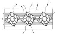
図1は、本発明に係る冷却装置の一形態例を示すものである。Figure 1 shows an example of one embodiment of a cooling device according to the present invention.
図1に例示するように、本発明に係る冷却装置1は、電動ファン2とヒートシンク3とを有している。As shown in FIG. 1, the
図1に示すように、本発明に係る冷却装置1において、ヒートシンクを構成する複数の放熱フィンfの配置幅(複数の放熱フィンfの長手方向と直交する方向における複数の放熱フィンfの設置幅)lは、電動ファン2を構成する回転羽根vの直径Dより大きい。As shown in FIG. 1, in the
上述したように、複数の放熱フィンfの配置幅lが電動ファン2を構成する回転羽根vの直径Dより大きいことにより、回転羽根vの回転領域全体に亘ってフィンf、f間の隙間が存在するため、冷却効率を容易に向上することができる。As described above, the arrangement width l of the multiple heat dissipation fins f is larger than the diameter D of the rotating blades v that make up the
図1に示すように、本発明に係る冷却装置1は、電動ファンを配置した側から正面視したときに、放熱フィンfの長手方向に対し電動ファン2が3°~45°の角度で傾斜して配置されている。As shown in FIG. 1, when viewed from the front from the side where the electric fan is arranged, the
本発明において、電動ファンが傾斜して配置されているとは、本発明に係る冷却装置を電動ファン側から正面視したときに、電動ファンの矩形状フレームを構成する一対の辺(上辺および下辺)がヒートシンクを構成する放熱フィンの長手方向に対して一定角度を成すように傾斜した状態でヒートシンク上に配置されていることを意味する。In the present invention, when the electric fan is arranged at an angle, it means that when the cooling device according to the present invention is viewed from the front from the electric fan side, a pair of sides (upper and lower sides) constituting the rectangular frame of the electric fan are arranged on the heat sink inclined at a certain angle with respect to the longitudinal direction of the heat dissipation fins constituting the heat sink.
図2は、本発明に係る冷却装置において、電動ファンの傾斜配置形態を説明するための図である。Figure 2 is a diagram to explain the inclined arrangement of the electric fan in the cooling device according to the present invention.
図2(a)は、ヒートシンク3に対し、電動ファン12が傾斜することなく配置された(放熱フィンfの長手方向に対する電動ファン12の傾斜角度が0°である)配置形態例を示す図である。
図2(a)に示す配置形態において、電動ファン12は、ヒートシンクを構成する放熱フィンfの長手方向に対して、電動ファンを構成する矩形状フレームrの一対の辺(図2(a)に示す電動ファンの矩形状フレームrの上辺および下辺)が平行になるようにヒートシンク13上に配置されている。 FIG. 2A shows an example of an arrangement in which the
In the arrangement shown in FIG. 2(a), the
これに対し、図2(b)は、ヒートシンク3に対し、電動ファン2が傾斜して配置された(放熱フィンfの長手方向に対して電動ファンが傾斜角度αで傾斜して配置された)本発明に係る冷却装置1の配置形態例を示す図である。
図2(b)に示す配置形態において、電動ファン2は、ヒートシンクを構成する放熱フィンfの長手方向に対して、電動ファンを構成する矩形状フレームrの一対の辺(図2(a)に示す電動ファンの矩形状フレームrの上辺および下辺)が角度αを成すようにヒートシンク上に傾斜して配置されている。 In contrast, FIG. 2(b) shows an example of an arrangement of the
In the arrangement shown in FIG. 2(b), the
図2(a)に示すように、ヒートシンクを構成する放熱フィンfの長手方向に対して、電動ファンを構成する矩形状フレームrの一対の辺(同図に示す矩形状フレームrの上辺および下辺)が平行になるように電動ファン12がヒートシンク13上に配置されている場合、固定部sを用いた電動ファン2の設置時に、ヒートシンク13端部の平坦部pへの固定ができず、このためにフィンfの設置領域に別途ボルト固定部材および固定用ボルト等の設置部材hを設ける必要がある。この場合、設置部材hの設置箇所等においてフィンを削除する必要が生じることから、冷却効率の低下を招くことになる。As shown in FIG. 2(a), when the
これに対して、図2(b)に示すようにヒートシンクを構成する放熱フィンfの長手方向に対して、電動ファンを構成する矩形状フレームrの一対の辺が角度αを成すようにヒートシンク上に傾斜して配置されている本発明に係る冷却装置1においては、固定部sを用いた電動ファン2の設置時に、ヒートシンク3端部の平坦部pへの固定が可能となり、フィンfの設置領域に別途ボルト固定部材や固定用ボルト等を設置したり、これ等を設置するためにフィン等を削除する必要がないことから、優れた冷却効率を容易に発揮することができる。In contrast, in the
本発明に係る冷却装置は、電動ファンを設置した側から正面視したときに、放熱フィンの長手方向に対し、電動ファンが、3°~45°の角度で傾斜して配置されたものであり、10°~45°の角度で傾斜して配置されたものであることがより好ましく、20°~40°の角度で傾斜して配置されたものであることがさらに好ましい。When viewed from the front from the side where the electric fan is installed, the cooling device according to the present invention is arranged so that the electric fan is inclined at an angle of 3° to 45° with respect to the longitudinal direction of the heat dissipation fins, preferably at an angle of 10° to 45°, and more preferably at an angle of 20° to 40°.
本発明に係る冷却装置は、電動ファン側から正面視したときに、放熱フィンの長手方向に対し、電動ファンが上記角度で傾斜して配置されていることにより、省スペースで冷却効率に優れた冷却装置を容易に提供することができる。When viewed from the front from the electric fan side, the cooling device of the present invention is arranged so that the electric fan is inclined at the above-mentioned angle with respect to the longitudinal direction of the heat dissipation fins, making it easy to provide a space-saving cooling device with excellent cooling efficiency.
本発明に係る冷却装置は、ヒートシンク上に電動ファンが配置されてなるものであり、図1に例示するように、本発明に係る冷却装置1が、ヒートシンク3上に電動ファン2が1台のみ配置されてなるものであってもよいし、図3に例示するように、本発明に係る冷却装置1が、ヒートシンク3上に電動ファン2が複数台(同図の例においては3台)配置されてなるものであってもよい。The cooling device according to the present invention has an electric fan arranged on a heat sink. As shown in FIG. 1, the
本発明に係る冷却装置が、紫外線照射光源の冷却用途に使用されるものである場合、光源の形状に対応するように、冷却装置を構成するヒートシンクも長尺形状(帯形状)となることから、係るヒートシンク上に配置される電動ファンも均一な冷却が可能となるように複数台が配置された形態であることが好ましく、(図3に例示するように)ヒートシンク上に電動ファンが複数台並置された形態であることがより好ましい。When the cooling device according to the present invention is used to cool an ultraviolet irradiation light source, the heat sink constituting the cooling device is also elongated (strip-shaped) to correspond to the shape of the light source, so it is preferable that multiple electric fans are arranged on the heat sink to enable uniform cooling, and it is even more preferable that multiple electric fans are arranged side by side on the heat sink (as exemplified in FIG. 3).
本発明に係る冷却装置が、ヒートシンク上に電動ファンを複数配置してなるものである場合、各電動ファンは同一のものであっても異なっていてもよいが、放熱フィンの配置領域全体に亘って冷却効果を均一化する上では、同一のものが好ましい。
また、本発明に係る冷却装置が、ヒートシンク上に電動ファンを複数配置してなるものである場合、各電動ファンの配置時における傾斜角度(図3の例における傾斜角度α)も、互いに同一であってもよいし異なっていてもよいが、放熱フィンの配置領域全体に亘って冷却効果を均一化する上では、傾斜角度も同一であることが好ましい。 When the cooling device of the present invention comprises a plurality of electric fans arranged on a heat sink, the electric fans may be the same or different, but it is preferable that they are the same in order to achieve a uniform cooling effect over the entire area in which the heat dissipation fins are arranged.
Furthermore, when the cooling device according to the present invention comprises a plurality of electric fans arranged on a heat sink, the inclination angles of the electric fans (inclination angle α in the example of FIG. 3) may be the same or different from one another, but in order to achieve a uniform cooling effect over the entire area in which the heat dissipation fins are arranged, it is preferable that the inclination angles are the same.
本発明に係る冷却装置が、ヒートシンク上に電動ファンを複数配置してなるものである場合、(図3に示す例においてaで表される)隣り合う電動ファンに収容される回転羽根の軸間の距離がより短い方が(複数の電動ファンがより密に配置された方が)冷却効率を高める上で好ましい。一方、複数の電動ファンは、(後述する図5(a)に示す例においてL6で示される)放熱フィンの長手方向と平行な方向におけるヒートシンクの長さ(ヒートシンクの横方向長さ)方向に一定間隔で分散して配置されている方がヒートシンク全体に亘って冷却効果を均一化することができる。このため、電動ファンの配置間隔は、上記事項を勘案した上で適宜決定することが好ましい。
本発明に係る冷却装置が、ヒートシンク上に電動ファンを複数配置してなるものである場合、(図3に示す例においてaで表される)隣り合う電動ファンに収容される回転羽根の軸間距離と、(後述する図4に示す例においてd2で表される)回転羽根を収容する矩形状フレームの一辺の長さにより規定される、「回転羽根の軸間距離/回転羽根を収容する矩形状フレームの一辺の長さ」は、1.10~1.70であることが好ましく、1.25~1.50であることがより好ましく、1.30~1.48であることがさらに好ましい。 In the case where the cooling device according to the present invention is configured by arranging a plurality of electric fans on a heat sink, it is preferable to increase the cooling efficiency by shortening the distance between the axes of the rotor blades housed in adjacent electric fans (represented by a in the example shown in FIG. 3) (the closer the plurality of electric fans are arranged), whereas it is preferable to disperse the plurality of electric fans at regular intervals along the length of the heat sink (the lateral length of the heat sink) in a direction parallel to the longitudinal direction of the heat dissipation fins (represented by L6 in the example shown in FIG. 5(a) described later), in order to make the cooling effect uniform over the entire heat sink. For this reason, it is preferable to determine the arrangement interval of the electric fans as appropriate, taking the above-mentioned factors into consideration.
When the cooling device according to the present invention comprises a plurality of electric fans arranged on a heat sink, the "axis-to-axis distance of the rotating blades/length of one side of the rectangular frame housing the rotating blades", which is defined by the axis-to-axis distance of the rotating blades housed in adjacent electric fans (represented by a in the example shown in FIG. 3) and the length of one side of the rectangular frame housing the rotating blades (represented by d2 in the example shown in FIG. 4 described later), is preferably 1.10 to 1.70, more preferably 1.25 to 1.50, and even more preferably 1.30 to 1.48.
図3に例示するように、本発明に係る冷却装置が複数の電動ファンを有するものである場合、全ての電動ファンがフィン間の隙間から(図3の紙面裏側に配置される)光源側に送風するものであってもよいし、全ての電動ファンが光源で加熱された空気をフィン間の隙間から(図3の紙面表側に)排出するものであってもよいし、一部の電動ファンがフィン間の隙間から(図3の紙面裏側に配置される)光源側に送風しつつ他の電動ファンが光源で加熱された空気をフィン間の隙間から(図3の紙面表側に)排出するものであってもよい。As illustrated in FIG. 3, when the cooling device according to the present invention has multiple electric fans, all of the electric fans may blow air toward the light source through the gaps between the fins (located on the back side of the page in FIG. 3), all of the electric fans may exhaust air heated by the light source through the gaps between the fins (on the front side of the page in FIG. 3), or some of the electric fans may blow air toward the light source through the gaps between the fins (located on the back side of the page in FIG. 3) while other electric fans exhaust air heated by the light source through the gaps between the fins (on the front side of the page in FIG. 3).
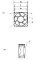
図4は、本発明に係る冷却装置を構成する電動ファンの形態例を示すものであり、図4(a)は、電動ファン2をその主表面側から正面視したときの図を示すものであり、図4(b)は、電動ファン2の側面図を示すものである。Figure 4 shows an example of the form of an electric fan constituting the cooling device according to the present invention, where Figure 4(a) shows a front view of the
本発明に係る冷却装置において、(図4(a)に示す例においてDで示される)電動ファンを構成する回転羽根の直径は、放熱フィンの長手方向と直交する方向における複数の放熱フィンの配置幅と同一であるかまたは同放熱フィンの配置幅未満の長さであれば、特に制限されない。In the cooling device according to the present invention, the diameter of the rotating blades that make up the electric fan (indicated by D in the example shown in FIG. 4(a)) is not particularly limited, so long as it is equal to or less than the arrangement width of the multiple heat dissipation fins in a direction perpendicular to the longitudinal direction of the heat dissipation fins.
本発明に係る冷却装置において、(図4(a)に示す例においてsで示される)矩形状フレームの角部に各々固定部が設けられる場合、(図4(a)においてd1で示される)隣り合う上記固定部s、s間の距離は、特に制限されない。
なお、本出願書類において、隣り合う固定部とは、矩形状フレームの一辺においてその両端部に設けられる固定部(図4(a)に例示する矩形状フレームrの一辺においてその両端部に設けられる固定部s、s)を意味する。 In the cooling device according to the present invention, when a fixing portion is provided at each corner of a rectangular frame (indicated by s in the example shown in FIG. 4(a)), the distance between adjacent fixing portions s, s (indicated by d1 in FIG. 4(a)) is not particularly limited.
In addition, in this application document, adjacent fixed portions refer to fixed portions provided at both ends of one side of a rectangular frame (fixed portions s, s provided at both ends of one side of a rectangular frame r as illustrated in Figure 4 (a)).
本発明に係る冷却装置においては、上記電動ファンを構成する矩形状フレームの角部に各々固定部が設けられ、上記電動ファンを構成する回転羽根の直径が上記矩形状フレームの隣り合う固定部間の距離より大きい(図4(a)に示す回転羽根の直径D>隣り合う固定部間の距離d1である)ことが適当である。In the cooling device according to the present invention, fixing parts are provided at each corner of the rectangular frame constituting the electric fan, and it is appropriate that the diameter of the rotating blades constituting the electric fan is larger than the distance between adjacent fixing parts of the rectangular frame (diameter D of the rotating blades shown in FIG. 4(a) > distance d1 between adjacent fixing parts).
本発明に係る冷却装置において、(図4(a)に示す例においてd2で示される)回転羽根を収容する矩形状フレームの一辺の長さは、(図4(a)に示す例においてDで示される)上記回転羽根の直径より大きく、回転羽根を収容し得る長さであれば、特に制限されない。
なお、本発明に係る冷却装置において、矩形状フレームは、通常、正面視したときに正方形状を有している。 In the cooling device of the present invention, the length of one side of the rectangular frame that houses the rotating blades (indicated by d2 in the example shown in Figure 4(a)) is not particularly limited, so long as it is longer than the diameter of the rotating blades (indicated by D in the example shown in Figure 4(a)) and is long enough to house the rotating blades.
In the cooling device according to the present invention, the rectangular frame usually has a square shape when viewed from the front.
図5は、本発明に係る冷却装置を構成するヒートシンクの形態例を示すものであり、図5(a)は、ヒートシンク3を電動ファンが配置される主表面側から正面視したときの図を示すものであり、図5(b)は、ヒートシンク3の側面図を示すものである。Figure 5 shows an example of a heat sink constituting the cooling device according to the present invention, where Figure 5(a) shows a front view of the
本発明に係る冷却装置において、(図5(a)に示す例においてL1で示される)ヒートシンクを構成する放熱フィンの長手方向の長さは、特に制限されない。In the cooling device according to the present invention, the longitudinal length of the heat dissipation fins constituting the heat sink (indicated by L1 in the example shown in FIG. 5(a)) is not particularly limited.
本発明に係る冷却装置において、(図5(b)に示す例においてL2で示される)ヒートシンクを構成する放熱フィンの高さ(放熱フィンの深さ)も、特に制限されない。In the cooling device according to the present invention, the height (depth) of the heat dissipation fins constituting the heat sink (indicated by L2 in the example shown in FIG. 5(b)) is not particularly limited.
本発明に係る冷却装置において、(図5(b)に示す例においてL3で示される)ヒートシンクを構成する放熱フィンの厚みも、特に制限されない。In the cooling device according to the present invention, the thickness of the heat dissipation fins constituting the heat sink (indicated by L3 in the example shown in FIG. 5(b)) is not particularly limited.
本発明に係る冷却装置において、(図5(b)に示す例においてL4で示される)ヒートシンクの厚みも、特に制限されない。In the cooling device according to the present invention, the thickness of the heat sink (shown as L4 in the example shown in FIG. 5(b)) is not particularly limited.
本発明に係る冷却装置において、(図5(a)に示す例においてL5で示される)放熱フィンの長手方向に直交する方向のヒートシンクの長さ(ヒートシンクの縦方向長さ)も、特に制限されない。In the cooling device according to the present invention, the length of the heat sink in the direction perpendicular to the longitudinal direction of the heat dissipation fins (indicated as L5 in the example shown in FIG. 5(a)) (the vertical length of the heat sink) is not particularly limited.
本発明に係る冷却装置において、(図5(a)に示す例においてL6で示される)放熱フィンの長手方向と平行な方向におけるヒートシンクの長さ(ヒートシンクの横方向長さ)の好適な範囲は、(図5(a)に示す例においてL1で示される)上記放熱フィンの長手方向の長さの好適な範囲と同様である。In the cooling device of the present invention, the preferred range of the length of the heat sink in the direction parallel to the longitudinal direction of the heat dissipation fin (shown as L6 in the example shown in FIG. 5(a)) (the lateral length of the heat sink) is the same as the preferred range of the longitudinal length of the heat dissipation fin (shown as L1 in the example shown in FIG. 5(a)).
本発明に係る冷却装置において、(図5(a)および図5(b)に示す例においてlで示される)放熱フィンの長手方向と直交する方向における複数の放熱フィンの配置幅は、ヒートシンク上に配置する電動ファンを構成する回転羽根の直径と同一であるか回転羽根の直径よりも大きな長さを有している。
なお、本出願書類において、複数の放熱フィンの配置幅とは、複数並置された放熱フィンの両端に形成された溝の底面における最外端間の距離(図5(b)で示す例におけるg1-g2間の距離)を意味する。 In the cooling device of the present invention, the arrangement width of the multiple heat dissipation fins in a direction perpendicular to the longitudinal direction of the heat dissipation fins (indicated by l in the example shown in Figures 5(a) and 5(b)) is equal to or greater than the diameter of the rotating blades of the electric fan arranged on the heat sink.
In this application, the arrangement width of multiple heat dissipation fins means the distance between the outermost ends of the bottom surfaces of the grooves formed at both ends of multiple juxtaposed heat dissipation fins (the distance between g1 and g2 in the example shown in Figure 5 (b)).
本発明に係る冷却装置において、(図5(a)および図5(b)に示す例においてfで示される)ヒートシンクを構成する複数の放熱フィンの数も、上記放熱フィンの長手方向と直交する方向における複数の放熱フィンの配置幅を満たす数であれば、特に制限されず、冷却効率等を考慮して適宜選定すればよい。In the cooling device according to the present invention, the number of heat dissipation fins constituting the heat sink (indicated by f in the example shown in Fig. 5(a) and Fig. 5(b)) is not particularly limited as long as it satisfies the arrangement width of the heat dissipation fins in a direction perpendicular to the longitudinal direction of the heat dissipation fins, and may be appropriately selected taking into consideration the cooling efficiency, etc.
本発明に係る冷却装置において、放熱フィンないしヒートシンクの構成材料としては、アルミニウム、銅、鉄、ステンレス等から選ばれる一種以上を挙げることができる。In the cooling device according to the present invention, the heat dissipation fin or heat sink may be made of one or more materials selected from aluminum, copper, iron, stainless steel, etc.
図6は、本発明に係る冷却装置において、ヒートシンク3上に電動ファン2を配置した配置例を示すものである。
図6に示すように、電動ファン2の矩形状フレームrは、通常、正面視したときに正方形状を成していることから、上記複数の放熱フィンの配置幅lが、上記電動ファンを構成する矩形状フレームの一辺の長さd2との関係で、下記式
電動ファンを構成する矩形状フレームの一辺の長さd2が複数の放熱フィンの配置幅lとの関係で上記関係を満たすものであることにより、矩形状フレームrの角部に設けられた固定部sにより、複数の放熱フィンfの配置領域の外側(図6に示す例における平坦部p)に電動ファン2を固定しつつ、電動ファン2を放熱フィンの長手方向に対して傾斜して配置することができる。 FIG. 6 shows an example of the arrangement of an
As shown in FIG. 6, the rectangular frame r of the
Since the length d2 of one side of the rectangular frame that constitutes the electric fan satisfies the above-mentioned relationship in relation to the arrangement width l of the multiple heat dissipation fins, the
また、図6に示す例においてL5で示される放熱フィン3の長手方向に直交する方向のヒートシンクの長さ(ヒートシンクの縦方向長さ)は、上記電動ファンを構成する矩形状フレームの一辺の長さd2との関係で、下記式
電動ファンを構成する矩形状フレームの一辺の長さd2が複数の放熱フィンの配置幅lとの関係で上記関係を満たすものであることにより、矩形状フレームrの角部に設けられた固定部sにより、電動ファン2を放熱フィンの長手方向に対して傾斜して配置しつつ、放熱フィンfの配置領域の外側(図6に示す例における平坦部p)に電動ファン2を容易に固定することができる。 In the example shown in FIG. 6, the length of the heat sink in the direction perpendicular to the longitudinal direction of the heat dissipation fins 3 (the vertical length of the heat sink) indicated by L5 is expressed by the following formula in relation to the length d2 of one side of the rectangular frame constituting the electric fan.
Since the length d2 of one side of the rectangular frame that constitutes the electric fan satisfies the above-mentioned relationship in relation to the arrangement width l of the multiple heat dissipation fins, the
次に、本発明に係る冷却装置において、ヒートシンクに放熱フィンを固定する固定形態について説明する。
図7~図9に示す固定形態例は、3台の同一の電動ファン2を配置した側から正面視したときに、放熱フィンfの長手方向に対し電動ファン2を45°の角度で傾斜してヒートシンクに配置した形態例である。 Next, a fixing manner in which the heat dissipating fins are fixed to the heat sink in the cooling device according to the present invention will be described.
The fixing configuration examples shown in Figures 7 to 9 are examples in which the
図7(a)は、(図示しない)長尺状の光源を冷却するための、ヒートシンク3および電動ファン2を備えた冷却装置1を、電動ファン2側から正面視したときの図であり、図7(b)は、図7(a)に示す冷却装置1の側面図を示すものである。Figure 7(a) is a diagram of a
図7(a)および図7(b)に示す冷却装置1において、電動ファン2は、ヒートシンク3の端部に設けた平坦部pに対し、矩形状フレームrの角部に設けた固定部sを用いてボルト等で固定することにより複数設置されている。In the
図8(a)も、(図示しない)長尺状の光源を冷却するための、ヒートシンク3および電動ファン2を備えた冷却装置1を、電動ファン2側から正面視したときの図であり、図8(b)は、図8(a)に示す冷却装置1の側面図を示すものである。Figure 8(a) is also a diagram of a
図8(a)および図8(b)に示す冷却装置1は、ヒートシンク3として、放熱フィンfの高さ(放熱フィンfの深さ)がヒートシンク3の端部に設けた平坦部pの高さよりも低いものを用いて電動ファン2を固定している以外は、図7(a)および図7(b)に示す冷却装置1の固定形態と共通する。The
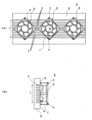
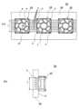
図9(a)も、(図示しない)長尺状の光源を冷却するための、ヒートシンク3および電動ファン2を備えた冷却装置1を、電動ファン2側から正面視したときの図であり、図9(b)は、図9(a)に示す冷却装置1のA-A線断面図を示すものである。Figure 9(a) is also a diagram of a
図9(a)および図9(b)に示す冷却装置1は、ヒートシンク3として、その端部に図7や図8に示すような平坦部pを有さないものを用いた例であり、この場合、ヒートシンク3の端部に別途支柱bを設けた上で、係る支柱bに対して矩形状フレームrの角部に設けた固定部sを用いて電動ファン2をボルト等で固定することにより複数設置されている。The
図7~図9に例示するように、本発明に係る冷却装置において、電動ファンは、矩形状フレームの角部に設けられ、矩形状フレームの対角線上に対向して位置する一対の固定部において記ヒートシンクに固定されていることが好ましい。
このような形態で電動ファンを矩形状フレームに固定することにより、放熱フィンが設けられている領域の外側に電動ファンを固定することができ、放熱フィンが設けられている領域に別途設置部材を設けたり、設置部材の設置箇所において放熱フィンを削除する必要がないことから、優れた冷却効率を容易に発揮することができる。 As illustrated in Figures 7 to 9, in the cooling device of the present invention, it is preferable that the electric fan is provided at a corner of a rectangular frame and fixed to the heat sink at a pair of fixing parts located diagonally opposite each other on the rectangular frame.
By fixing the electric fan to the rectangular frame in this manner, the electric fan can be fixed outside the area where the heat dissipation fins are provided, and there is no need to provide a separate installation member in the area where the heat dissipation fins are provided, or to remove the heat dissipation fins at the installation location of the installation member, so excellent cooling efficiency can be easily achieved.
図7~図9に示す固定形態例においては、放熱フィンfの長手方向と直交する方向における複数の放熱フィンの配置幅lが電動ファン2を構成する回転羽根の直径Dよりも大きな長さを有するとともに、電動ファン2を配置した側から正面視したときに、放熱フィンfの長手方向に対し電動ファン2を傾斜させつつヒートシンク3の端部に固定しているため、複数のフィンfの配置幅l全体に亘って、フィンf、f間の隙間から光源側に送風し、または光源で加熱された空気をフィン間の隙間から排出して、光源を冷却することができる。In the example of the fixing configuration shown in Figures 7 to 9, the arrangement width l of the multiple heat dissipation fins in the direction perpendicular to the longitudinal direction of the heat dissipation fins f is greater than the diameter D of the rotating blades that make up the
本発明によれば、省スペースで冷却効率に優れた冷却装置を提供することができる。The present invention provides a space-saving cooling device with excellent cooling efficiency.
次に、本発明に係る光照射装置について説明する。
本発明に係る光照射装置は、長尺状の光源と本発明の冷却装置とを有し、前記長尺状の光源に対し、前記電動ファンを設置した側とは反対側のヒートシンクの主表面が対向するように前記冷却装置が配置されていることを特徴とするものである。 Next, the light irradiation device according to the present invention will be described.
The light irradiation device of the present invention has an elongated light source and the cooling device of the present invention, and is characterized in that the cooling device is arranged so that the main surface of the heat sink on the opposite side to the side on which the electric fan is installed faces the elongated light source.
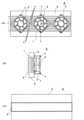
図10は、図7に示すヒートシンク3に電動ファン2を固定した冷却装置において、さらに(ヒートシンク3と対向するように)電動ファン2を設けた側とは反対側のヒートシンク3の主表面に長尺状の光源5を固定した光照射装置4を示すものである。Figure 10 shows a
図10(a)は、長尺状の光源5を有するとともに、長尺状の光源5を冷却するためのヒートシンク3および電動ファン2を備えた光照射装置4を、電動ファン2側から正面視したときの図であり、図10(b)は、図10(a)に示す光照射装置4の側面図を示すものであり、図10(c)は、図10(a)に示す光照射装置4を、長尺状の光源5側から正面視したときの図である。Figure 10(a) is a diagram of a
図10(a)~図10(c)に示す冷却装置1において、電動ファン2は、ヒートシンク3の端部に設けた平坦部pに対し、矩形状フレームrの角部に設けた固定部sを用いてボルト等で固定することにより複数設置されている。In the
図10に例示する光照射装置4においては、長尺状の光源5から図10(b)の左側に光照射しつつ、直径Dを有する回転羽根vを回転させることにより、複数のフィンfの配置幅l全体に亘って、フィンf、f間の隙間から光源5側に送風し、または光源で加熱された空気をフィン間の隙間から排出して、光源5を効果的に冷却することができる。In the
図10に例示するように、本発明に係る光照射装置が複数の電動ファンを有する冷却装置を備えたものである場合、全ての電動ファンがフィン間の隙間から光源側に送風するものであってもよいし、全ての電動ファンが光源で加熱された空気をフィン間の隙間から(電動ファンの設置側に)排出するものであってもよいし、一部の電動ファンがフィン間の隙間から光源側に送風しつつ他の電動ファンが光源で加熱された空気をフィン間の隙間から(電動ファンの設置側に)排出するものであってもよい。As shown in FIG. 10, when the light irradiation device according to the present invention is equipped with a cooling device having multiple electric fans, all the electric fans may blow air toward the light source through the gaps between the fins, or all the electric fans may exhaust air heated by the light source through the gaps between the fins (toward the installation side of the electric fans), or some of the electric fans may blow air toward the light source through the gaps between the fins while other electric fans exhaust air heated by the light source through the gaps between the fins (toward the installation side of the electric fans).
本発明に係る光照射装置は、筐体を有するものであってもよい。
筐体を有する光照射装置の形態例としては、例えば、ヒートシンクの片側主表面に電動ファンを、反対側主表面に光源を固定した上で、これ等を収容する筐体中に得られた固定物を収容する形態を挙げることができる。 The light irradiation device according to the present invention may have a housing.
An example of a light irradiation device having a housing is one in which an electric fan is fixed to one main surface of a heat sink and a light source is fixed to the opposite main surface, and the obtained fixed objects are housed in a housing that houses these.
本発明によれば、省スペースで冷却効率に優れた冷却装置を有する光照射手段を提供することができる。The present invention provides a light irradiation means having a space-saving cooling device with excellent cooling efficiency.
以下、実施例および比較例により本発明を更に説明するが、本発明はその要旨を超えない限り下記の実施例に限定されるものではない。The present invention will be further explained below with reference to examples and comparative examples, but the present invention is not limited to the following examples as long as they do not exceed the gist of the invention.
(実施例1~実施例4、比較例1)
<光照射装置の構成>
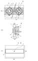
以下の実施例および比較例においては、図11に示す形態を有する光照射装置4を用いて照射試験を行った。
図11(a)は、長尺状の光源5を有するとともに、長尺状の光源5を冷却するための、ヒートシンク3に電動ファン2を2台固定した冷却装置を有する光照射装置4を、電動ファン2を設けた側から正面視したときの図であり、図11(b)は図11(a)に示す光照射装置4の側面図を示すものであり、図11(c)は、図11(a)に示す光照射装置4を、長尺状の光源5を設けた側から正面視したときの図である。
以下の実施例および比較例においては、光照射装置4を構成する、電動ファン2、ヒートシンク3および光源5として、以下に示すものを用い、周囲環境温度25℃の条件下、光源5から図11(b)の左側に光照射しつつ、電動ファン2、2を駆動して光源5側に送風して冷却処理を行ったときの、冷却処理を開始して温度飽和したとき(一定温度に達したとき)における光源5の温度Tを測定した。光源5の温度の測定位置は、図11(c)に示す、光源5の長手方向中央部(2台の電動ファン2、2を構成する回転羽根v、vの軸間の中央部に対応する位置)cとした。
実施例1~実施例4および比較例1においては、図11(a)に示す、2台の電動ファン2、2を電動ファン側から正面視したときに、放熱フィンfの長手方向に対する2台の電動ファン2、2の傾斜角度αおよび2台の電動ファン2、2を各々構成する回転羽根の軸間距離aを表1に示すとおり変化させた。
なお、以下に示す各符号は、図11に付した符号と対応するものである。(Examples 1 to 4, Comparative Example 1)
<Configuration of Light Irradiation Device>
In the following examples and comparative examples, irradiation tests were carried out using a
FIG. 11(a) is a diagram of a
In the following examples and comparative examples, the
In Examples 1 to 4 and Comparative Example 1, when the two
The reference characters shown below correspond to those in FIG.
<ヒートシンク>
ヒートシンク3として、放熱フィンfを11枚長手方向に平行に配置したものを使用した。放熱フィンfを含むヒートシンクの構成材としては全てアルミニウムを採用した。
(放熱フィンサイズ)
放熱フィンの長手方向の長さL1:325mm
放熱フィンの高さ(放熱フィンの深さ)L2:32mm
放熱フィンの厚みL3:5mm
放熱フィンの長手方向と直交する方向における複数の放熱フィンの配置幅l:115mm
(ヒートシンク本体サイズ)
ヒートシンクの厚みL4:45mm
放熱フィンfの長手方向に直交する方向のヒートシンクの長さL5:175mm
放熱フィンの長手方向と平行な方向におけるヒートシンクの長さL6:325mm<Heat sink>
The
(heat dissipation fin size)
Length of heat sink fin in the longitudinal direction L1: 325 mm
Heat sink height (heat sink depth) L2: 32 mm
Thickness of heat sink fin L3: 5mm
Arrangement width l of the multiple heat dissipation fins in a direction perpendicular to the longitudinal direction of the heat dissipation fins: 115 mm
(Heat sink body size)
Heat sink thickness L4: 45 mm
Length L5 of the heat sink in a direction perpendicular to the longitudinal direction of the heat dissipation fin f: 175 mm
Length of the heat sink in the direction parallel to the longitudinal direction of the heat dissipation fin L6: 325 mm
<電動ファン>
電動ファン2、2として、いずれも山洋電気(株)製9G1248G101を用いた。
矩形状フレームrの1辺の長さ:120mm
矩形状フレームrの厚さ:38mm
隣り合う固定部s、s間の距離: 104.8mm
回転羽根vの直径D:113.5mm
定格電圧:48V
定格電流:0.25A
定格入力:12W
定格回転速度:3600min-1<Electric fan>
As the
Length of one side of rectangular frame r: 120 mm
Thickness of rectangular frame r: 38 mm
Distance between adjacent fixed parts s, s: 104.8 mm
Diameter D of rotor blade v: 113.5 mm
Rated voltage: 48V
Rated current: 0.25A
Rated input: 12W
Rated rotation speed: 3600 min-1
<光源>
光源として、発熱部が横80mm、縦320mm、厚さ1mmのサイズを有する発熱量200Wである紫外線照射光源を用いた。<Light source>
As the light source, an ultraviolet irradiation light source with a heat generating portion having dimensions of 80 mm in width, 320 mm in length and 1 mm in thickness and a heat output of 200 W was used.
上記測定で得られた光源5の温度T(光源5の長手方向中央部(2台の電動ファン2、2を構成する回転羽根v、vの軸間の中央部に対応する位置)cにおける温度)を表1に記載する。
また、比較例1で測定された温度に対する各実施例で測定された温度の温度差ΔTを表1に併記する。 The temperature T of the
Table 1 also shows the temperature difference ΔT between the temperature measured in Comparative Example 1 and the temperature measured in each Example.

表1より、実施例1~実施例4においては、電動ファン側から正面視したときに、放熱フィンの長手方向に対し電動ファンが所定の傾斜角度で傾斜して配置されているために、光源5の温度を効果的に低減し得ることが分かる。From Table 1, it can be seen that in Examples 1 to 4, when viewed from the front from the electric fan side, the electric fan is positioned at a predetermined inclination angle with respect to the longitudinal direction of the heat dissipation fins, so that the temperature of the
一方、表1より、比較例1においては、電動ファン側から正面視したときに、放熱フィンの長手方向に対し電動ファンが平行に配置されており、フィンfの設置領域に別途ボルト固定部材および固定用ボルト等の設置部材を設け、フィンの一部を削除したものであることから、光源5の温度低減効果が低いことが分かる。On the other hand, from Table 1, it can be seen that in Comparative Example 1, when viewed from the front from the electric fan side, the electric fan is arranged parallel to the longitudinal direction of the heat dissipation fins, and installation members such as a bolt fixing member and a fixing bolt are provided separately in the installation area of the fin f, and part of the fin is removed, so the temperature reduction effect of the
本発明によれば、省スペースで冷却効率に優れた冷却装置を提供することができるとともに、係る冷却装置を有する光照射手段を提供することができる。The present invention can provide a space-saving cooling device with excellent cooling efficiency, and can also provide a light irradiation means having such a cooling device.
1、11 冷却装置
2、12 電動ファン
3、13 ヒートシンク
4 光照射装置
5 光源
v 回転羽根
f 放熱フィン
s 固定部
r 矩形状フレーム
p 平坦部
l 放熱フィンの配置幅
b 支柱
h 設置部材
D 回転羽根の直径
d1 隣り合う上記固定部間の距離
d2 矩形状フレームの一辺の長さREFERENCE SIGNS
D: Diameter of the rotor blade d1: Distance between adjacent fixed parts d2: Length of one side of the rectangular frame
Claims (5)
Translated fromJapanese前記長尺状のヒートシンク上の長手方向に複数配置された、矩形状フレーム内に回転羽根が収容された電動ファンとを有し、
前記放熱フィンの長手方向と直交する方向における前記複数の放熱フィンの配置幅が前記電動ファンを構成する回転羽根の直径と同一またはそれ以上の長さを有し、
前記電動ファン側から正面視したときに、前記放熱フィンの長手方向に対し前記複数の電動ファンが20°~40°の同一の角度で傾斜して配置され、
前記電動ファンの矩形状フレームが止め具で固定されており、当該止め具による固定位置が前記複数の放熱フィンの配置位置の外側に設けられたヒートシンクの平坦部のみである
ことを特徴とする冷却装置。 an elongated heat sink having a plurality of heat dissipation fins arranged in parallel in a longitudinal direction and spaced apart from each other;
a plurality of electric fans each having a rotating blade housed within a rectangular frame arranged in a longitudinal direction on the elongated heat sink;
a width of the plurality of heat dissipation fins in a direction perpendicular to the longitudinal direction of the heat dissipation fins is equal to or greater than a diameter of a rotating blade constituting the electric fan;
When viewed from the front from the electric fan side,the electric fans are arranged to be inclined atthe same angle of20° to 40° with respect to the longitudinal direction of the heat dissipation fins,
A cooling device characterized in that the rectangular frame of the electric fan is fixed with fasteners, and the fixing positions using the fasteners are only flat portions of the heat sink located outside the positions where the multiple heat dissipation fins are arranged.

前記電動ファンを構成する回転羽根の設置領域全体に前記ヒートシンクの放熱フィンが設けられている、
請求項1~請求項3のいずれかに記載の冷却装置。 a fixing portion is provided at each corner of a rectangular frame constituting the electric fan, and a diameter of a rotating blade constituting the electric fan is larger than a distance between adjacent fixing portions of the rectangular frame,
The heat sink has heat dissipation fins disposed over the entire area where the rotor blades constituting the electric fan are installed.
The cooling device according to any one of claims 1 to 3.
前記長尺状の光源に対し、前記電動ファンを設置した側とは反対側のヒートシンクの主表面が対向するように前記冷却装置が配置されている
ことを特徴とする光照射装置。
A long light source and the cooling device according to any one of claims 1 to 4,
A light irradiation device, characterized in that the cooling device is disposed so that a main surface of the heat sink on an opposite side to a side on which the electric fan is installed faces the elongated light source.
Priority Applications (1)
| Application Number | Priority Date | Filing Date | Title |
|---|---|---|---|
| JP2020035883AJP7705704B2 (en) | 2020-03-03 | 2020-03-03 | Cooling device and light irradiation device |
Applications Claiming Priority (1)
| Application Number | Priority Date | Filing Date | Title |
|---|---|---|---|
| JP2020035883AJP7705704B2 (en) | 2020-03-03 | 2020-03-03 | Cooling device and light irradiation device |
Publications (2)
| Publication Number | Publication Date |
|---|---|
| JP2021141134A JP2021141134A (en) | 2021-09-16 |
| JP7705704B2true JP7705704B2 (en) | 2025-07-10 |
Family
ID=77669315
Family Applications (1)
| Application Number | Title | Priority Date | Filing Date |
|---|---|---|---|
| JP2020035883AActiveJP7705704B2 (en) | 2020-03-03 | 2020-03-03 | Cooling device and light irradiation device |
Country Status (1)
| Country | Link |
|---|---|
| JP (1) | JP7705704B2 (en) |
Citations (4)
| Publication number | Priority date | Publication date | Assignee | Title |
|---|---|---|---|---|
| JP2005150341A (en) | 2003-11-14 | 2005-06-09 | Yamasa Kk | Forcible air-cooling structure and game machine |
| JP2005352427A (en) | 2004-06-14 | 2005-12-22 | Sony Corp | Liquid crystal display device and back light device |
| JP2008170729A (en) | 2007-01-11 | 2008-07-24 | Sony Corp | Backlight device and display device |
| JP2009130146A (en) | 2007-11-26 | 2009-06-11 | Nippon Light Metal Co Ltd | Heat exchanger, electronic equipment storage box and electronic equipment test box |
Family Cites Families (4)
| Publication number | Priority date | Publication date | Assignee | Title |
|---|---|---|---|---|
| JP3503822B2 (en)* | 2001-01-16 | 2004-03-08 | ミネベア株式会社 | Axial fan motor and cooling device |
| TW535859U (en)* | 2002-05-22 | 2003-06-01 | Delta Electronics Inc | Fan frame |
| JP4115212B2 (en)* | 2002-09-12 | 2008-07-09 | 古河電気工業株式会社 | Heat sink with fan |
| JP6862803B2 (en)* | 2016-12-01 | 2021-04-21 | 岩崎電気株式会社 | Irradiation device |
- 2020
- 2020-03-03JPJP2020035883Apatent/JP7705704B2/enactiveActive
Patent Citations (4)
| Publication number | Priority date | Publication date | Assignee | Title |
|---|---|---|---|---|
| JP2005150341A (en) | 2003-11-14 | 2005-06-09 | Yamasa Kk | Forcible air-cooling structure and game machine |
| JP2005352427A (en) | 2004-06-14 | 2005-12-22 | Sony Corp | Liquid crystal display device and back light device |
| JP2008170729A (en) | 2007-01-11 | 2008-07-24 | Sony Corp | Backlight device and display device |
| JP2009130146A (en) | 2007-11-26 | 2009-06-11 | Nippon Light Metal Co Ltd | Heat exchanger, electronic equipment storage box and electronic equipment test box |
Also Published As
| Publication number | Publication date |
|---|---|
| JP2021141134A (en) | 2021-09-16 |
Similar Documents
| Publication | Publication Date | Title |
|---|---|---|
| CN110389474B (en) | Liquid crystal display device having a plurality of pixel electrodes | |
| TW411756B (en) | Heat generating element cooling unit with louvers | |
| KR20110082844A (en) | Cooling device and display device having same | |
| KR101831196B1 (en) | Heat-generating element cooling apparatus for inverter | |
| US20080101035A1 (en) | Heat-dissipating assembly structure | |
| JP3190306U (en) | Light module heatsink | |
| JP7705704B2 (en) | Cooling device and light irradiation device | |
| CN102045988A (en) | Radiating device | |
| KR100528917B1 (en) | Plasma display device | |
| JP2012004454A (en) | Air cooling heat dissipation device | |
| JPH10302540A (en) | Device equipped with lamp cooling mechanism and lamp cooling method | |
| CN209977825U (en) | Illumination zone adjustable LED floodlight | |
| KR102539956B1 (en) | Air cooling heat sink for UV LED curing machine | |
| JP2010165761A (en) | Electronic component cooling structure | |
| CN211457421U (en) | Electronic ballast for ultraviolet lamp | |
| CN102568760B (en) | Fin-inserting type radiator and heat radiating device with same | |
| KR101336122B1 (en) | plasma display panel and multi plasma display panel using the same | |
| CN1243463C (en) | Heat emission module structure for electronic device | |
| CN2724201Y (en) | radiator structure | |
| KR100649213B1 (en) | Plasma display device | |
| CN207399734U (en) | A kind of built-in power amplifier module radiator | |
| CN218336911U (en) | High-efficient heating panel of machine case | |
| CN2687846Y (en) | heat sink | |
| KR20200084114A (en) | Apparatus for radiating heat of led lamp | |
| KR101760002B1 (en) | A cooling device for invertor of heanting induction |
Legal Events
| Date | Code | Title | Description |
|---|---|---|---|
| A621 | Written request for application examination | Free format text:JAPANESE INTERMEDIATE CODE: A621 Effective date:20221219 | |
| A977 | Report on retrieval | Free format text:JAPANESE INTERMEDIATE CODE: A971007 Effective date:20230912 | |
| A131 | Notification of reasons for refusal | Free format text:JAPANESE INTERMEDIATE CODE: A131 Effective date:20230926 | |
| A521 | Request for written amendment filed | Free format text:JAPANESE INTERMEDIATE CODE: A523 Effective date:20231124 | |
| A02 | Decision of refusal | Free format text:JAPANESE INTERMEDIATE CODE: A02 Effective date:20240220 | |
| A521 | Request for written amendment filed | Free format text:JAPANESE INTERMEDIATE CODE: A523 Effective date:20240520 | |
| A911 | Transfer to examiner for re-examination before appeal (zenchi) | Free format text:JAPANESE INTERMEDIATE CODE: A911 Effective date:20240528 | |
| A912 | Re-examination (zenchi) completed and case transferred to appeal board | Free format text:JAPANESE INTERMEDIATE CODE: A912 Effective date:20240726 | |
| A521 | Request for written amendment filed | Free format text:JAPANESE INTERMEDIATE CODE: A523 Effective date:20250411 | |
| A61 | First payment of annual fees (during grant procedure) | Free format text:JAPANESE INTERMEDIATE CODE: A61 Effective date:20250630 | |
| R150 | Certificate of patent or registration of utility model | Ref document number:7705704 Country of ref document:JP Free format text:JAPANESE INTERMEDIATE CODE: R150 |