JP7705399B2 - Improved Turret Mooring System - Google Patents
Improved Turret Mooring SystemDownload PDFInfo
- Publication number
- JP7705399B2 JP7705399B2JP2022536977AJP2022536977AJP7705399B2JP 7705399 B2JP7705399 B2JP 7705399B2JP 2022536977 AJP2022536977 AJP 2022536977AJP 2022536977 AJP2022536977 AJP 2022536977AJP 7705399 B2JP7705399 B2JP 7705399B2
- Authority
- JP
- Japan
- Prior art keywords
- turret
- mooring
- chain table
- upstream
- downstream
- Prior art date
- Legal status (The legal status is an assumption and is not a legal conclusion. Google has not performed a legal analysis and makes no representation as to the accuracy of the status listed.)
- Active
Links
Images


Classifications
- B—PERFORMING OPERATIONS; TRANSPORTING
- B63—SHIPS OR OTHER WATERBORNE VESSELS; RELATED EQUIPMENT
- B63B—SHIPS OR OTHER WATERBORNE VESSELS; EQUIPMENT FOR SHIPPING
- B63B21/00—Tying-up; Shifting, towing, or pushing equipment; Anchoring
- B63B21/50—Anchoring arrangements or methods for special vessels, e.g. for floating drilling platforms or dredgers
- B63B21/507—Anchoring arrangements or methods for special vessels, e.g. for floating drilling platforms or dredgers with mooring turrets
- F—MECHANICAL ENGINEERING; LIGHTING; HEATING; WEAPONS; BLASTING
- F03—MACHINES OR ENGINES FOR LIQUIDS; WIND, SPRING, OR WEIGHT MOTORS; PRODUCING MECHANICAL POWER OR A REACTIVE PROPULSIVE THRUST, NOT OTHERWISE PROVIDED FOR
- F03B—MACHINES OR ENGINES FOR LIQUIDS
- F03B13/00—Adaptations of machines or engines for special use; Combinations of machines or engines with driving or driven apparatus; Power stations or aggregates
- F03B13/12—Adaptations of machines or engines for special use; Combinations of machines or engines with driving or driven apparatus; Power stations or aggregates characterised by using wave or tide energy
- F03B13/26—Adaptations of machines or engines for special use; Combinations of machines or engines with driving or driven apparatus; Power stations or aggregates characterised by using wave or tide energy using tide energy
- F03B13/264—Adaptations of machines or engines for special use; Combinations of machines or engines with driving or driven apparatus; Power stations or aggregates characterised by using wave or tide energy using tide energy using the horizontal flow of water resulting from tide movement
- B—PERFORMING OPERATIONS; TRANSPORTING
- B63—SHIPS OR OTHER WATERBORNE VESSELS; RELATED EQUIPMENT
- B63B—SHIPS OR OTHER WATERBORNE VESSELS; EQUIPMENT FOR SHIPPING
- B63B21/00—Tying-up; Shifting, towing, or pushing equipment; Anchoring
- B63B21/50—Anchoring arrangements or methods for special vessels, e.g. for floating drilling platforms or dredgers
- B63B2021/505—Methods for installation or mooring of floating offshore platforms on site
- B—PERFORMING OPERATIONS; TRANSPORTING
- B63—SHIPS OR OTHER WATERBORNE VESSELS; RELATED EQUIPMENT
- B63J—AUXILIARIES ON VESSELS
- B63J3/00—Driving of auxiliaries
- B63J3/04—Driving of auxiliaries from power plant other than propulsion power plant
- B63J2003/046—Driving of auxiliaries from power plant other than propulsion power plant using wind or water driven turbines or impellers for power generation
- Y—GENERAL TAGGING OF NEW TECHNOLOGICAL DEVELOPMENTS; GENERAL TAGGING OF CROSS-SECTIONAL TECHNOLOGIES SPANNING OVER SEVERAL SECTIONS OF THE IPC; TECHNICAL SUBJECTS COVERED BY FORMER USPC CROSS-REFERENCE ART COLLECTIONS [XRACs] AND DIGESTS
- Y02—TECHNOLOGIES OR APPLICATIONS FOR MITIGATION OR ADAPTATION AGAINST CLIMATE CHANGE
- Y02E—REDUCTION OF GREENHOUSE GAS [GHG] EMISSIONS, RELATED TO ENERGY GENERATION, TRANSMISSION OR DISTRIBUTION
- Y02E10/00—Energy generation through renewable energy sources
- Y02E10/30—Energy from the sea, e.g. using wave energy or salinity gradient
Landscapes
- Engineering & Computer Science (AREA)
- Mechanical Engineering (AREA)
- Chemical & Material Sciences (AREA)
- Combustion & Propulsion (AREA)
- Ocean & Marine Engineering (AREA)
- Oceanography (AREA)
- General Life Sciences & Earth Sciences (AREA)
- Life Sciences & Earth Sciences (AREA)
- General Engineering & Computer Science (AREA)
- Other Liquid Machine Or Engine Such As Wave Power Use (AREA)
- Earth Drilling (AREA)
- Cutting Tools, Boring Holders, And Turrets (AREA)
- Gripping On Spindles (AREA)
Description
Translated fromJapanese本発明は、タレット係留システムに関し、特に、潮汐流からエネルギーを引き出すためにタービンアセンブリを使用するようになっているタレット係留システムに関する。The present invention relates to a turret mooring system, and more particularly to a turret mooring system that uses a turbine assembly to extract energy from tidal currents.
タレット係留は、係留された船舶が局所的な流れに応じて(ヨー軸の周りで)旋回できるようにする係留である。一般に、タレット係留は、支配的な流れ方向がない場所で使用され、係留された船舶が局所的な風及び波の力に応じて揺動することを意味する。原則として、これらの流れ及び力はいかなる方向からも来ることができるため、タレット係留設備は、さもなければ風及び波によって引き起こされるドリフトに全方向で抵抗するために、中心点(タレット)に収束する略円形の配置を成して水底に固定される。Turret mooring is a mooring that allows the moored vessel to pivot (around the yaw axis) in response to local currents. Generally, turret moorings are used where there is no dominant current direction, meaning that the moored vessel will sway in response to local wind and wave forces. In principle, these currents and forces can come from any direction, so turret moorings are fixed to the water bottom in a roughly circular arrangement converging on a central point (the turret) to resist drift that would otherwise be caused by wind and waves in all directions.
潮汐発電システムでは、流れが強く双方向であり、すなわち、流れは、潮汐が入ってくるときには第1の方向で強く、満潮では実質的に0であり、潮汐が出て行くときには第2の方向(第1の方向と実質的に反対)で強く、干潮では実質的に0であり、その時点でサイクルが繰り返される。したがって、タレット係留は、潮汐発電システムにとって理想的な候補であると思われる。これは、タレット係留によって電力システムが旋回して現在の流れと合うことができるとともに、双方向の局所的な流れを構成する2つの主な方向のそれぞれで流れによって導入されるドリフト動作に抵抗するために水底上の2つの固定ポイント、すなわち、上流側固定ポイント及び下流側固定ポイントのみが必要とされるからである。In a tidal power system, the currents are strong and bidirectional, i.e., the currents are strong in a first direction when the tide is coming in and essentially zero at high tide, and strong in a second direction (substantially opposite to the first direction) when the tide is going out and essentially zero at low tide, at which point the cycle repeats. Turret moorings therefore appear to be an ideal candidate for tidal power systems, as they allow the power system to pivot to match the currents and only two fixed points on the water bottom are required to resist the drift motion introduced by the currents in each of the two main directions that make up the bidirectional local currents, namely an upstream fixed point and a downstream fixed point.
しかしながら、典型的なタレット係留システムは、通常、比較的深海の場所に設置され、例えば、この場合、平均水深dM=(dH+dL)/2は、満潮と干潮との間の深さの変化δd=dH-dLよりもはるかに大きく、ここで、dM,δd,dH及びdLはそれぞれ、平均水深、深さの変化、満潮時の深さ、干潮時の深さである。そのような場合、係留された船舶の上昇及び下降は、水底から船舶までの一般的な距離と比較して小さく、係留システムの形態は、潮汐サイクルにわたって比較的変化しない。 However, typical turret mooring systems are usually installed in relatively deep water locations, for example, where the mean water depthdM = (dH +dL )/2 is much larger than the change in depth between high and low tide δd =dH -dL , wheredM , δd, dH anddL are the mean water depth, change in depth, depth at high tide and depth at low tide, respectively. In such cases, the rise and fall of a moored vessel is small compared to the typical distance of the vessel from the water bottom, andthe configuration of the mooring system remains relatively unchanged over the tidal cycle.
これは、一般に、潮汐発電システムが係留される場所には当てはまらない。ここでは、発電ポテンシャルを最大にするために、比較的大きな潮汐範囲が選択される。これは、通常、アセンブリを沿岸近くに固定することを意味する。沿岸が大きな潮汐範囲及び流れを生み出す傾向がある海岸線に関連する地理的特徴だからである。更に、アセンブリを沿岸近くに設置すると、設置が簡単になるとともに、発電された電力の沿岸への伝送も容易になる。これにより、dMに対するδdの比率が比較的大きくなる傾向があり、これにより、係留ラインが干潮時に弛むことになる。弛んだラインは、回転に抵抗するのが不十分であり、タレットを水底に対して静止状態に保持できない可能性があることが分かっている。全体的な結果として、潮汐が変化すると、アセンブリがタレットの周りを旋回して局所的な流れと合うのではなく、タレットを含むアセンブリ全体がヨーイングする。数サイクルにわたって、これにより係留ラインが絡まったりねじれたりする可能性がある。流れの強い双方向性に起因して、係留ラインの数を増加させても、絡みに抵抗することにおいて殆ど又は全く効果がない。実際に、更なる係留ラインを水底に固定するコスト及び複雑さの増大とは別に、より多くの係留ラインが互いに簡単に絡み合うことからより多くの係留ラインが絡み合いを悪化させる可能性があるため、より多くの係留ラインは望ましくない。 This is generally not the case where tidal power generation systems are moored. Here, a relatively large tidal range is selected to maximize the power generation potential. This usually means anchoring the assembly close to the coast, as this is a geographic feature associated with the coastline that tends to generate large tidal ranges and currents. Furthermore, locating the assembly close to the coast simplifies installation and facilitates transmission of generated power to the coast. This tends to result in a relatively large ratio of δd todM , which causes the mooring lines to go slack at low tide. It has been found that slack lines may not be able to resist rotation sufficiently to hold the turret stationary relative to the bottom. The overall result is that when the tides change, the entire assembly, including the turret, yaws, rather than the assembly pivoting around the turret to match the local currents. Over several cycles, this can cause the mooring lines to tangle and twist. Due to the strong bidirectional nature of the currents, increasing the number of mooring lines has little or no effect in resisting tangling. In fact, more mooring lines are undesirable because, apart from the increased cost and complexity of anchoring additional mooring lines to the water bottom, more mooring lines can exacerbate entanglement as they easily become entangled with each other.
本発明は、上記課題に対処することを目的とする。The present invention aims to address the above problems.
上記の課題に対する一連の密接に関連した解決策が本明細書中で提示される。A series of closely related solutions to the above problems are presented herein.
本明細書には、潮汐タービンアセンブリのためのタレット係留システムであって、タレットであって、潮汐タービンアセンブリに装着するため及び回転軸を中心としたタレットと潮汐タービンアセンブリとの間の相対的な動作を可能にするためのシャフトと、シャフトの下端部に固定されるチェーンテーブルとを有するものと、水底上の単一の上流側固定ポイントをチェーンテーブルの上流側部分に結合するための上流側係留ラインと、水底上の単一の下流側固定ポイントをチェーンテーブルの下流側部分に結合するための下流側係留ラインとを備え、上流側係留ラインが、チェーンテーブルの上流側部分上の2つの離間した上流側取り付けポイントに結合するための二股係留ラインである、及び/又は、下流側係留ラインが、チェーンテーブルの下流側部分上の2つの離間した下流側取り付けポイントに結合するための二股係留ラインである、タレット係留システムが開示される。Disclosed herein is a turret mooring system for a tidal turbine assembly, comprising a turret having a shaft for mounting to the tidal turbine assembly and for enabling relative movement between the turret and the tidal turbine assembly about an axis of rotation, and a chain table fixed to a lower end of the shaft, an upstream mooring line for connecting a single upstream fixed point on the bottom of the water to an upstream portion of the chain table, and a downstream mooring line for connecting a single downstream fixed point on the bottom of the water to a downstream portion of the chain table, wherein the upstream mooring line is a bifurcated mooring line for connecting to two spaced apart upstream attachment points on the upstream portion of the chain table and/or the downstream mooring line is a bifurcated mooring line for connecting to two spaced apart downstream attachment points on the downstream portion of the chain table.
本明細書で使用される「上流側」及び「下流側」という用語は、ほぼ反対方向である、上昇する及び下降する潮汐中の支配的な流れ方向を広く指す。潮汐が流出から流入へ(及びその逆)変化すると、上流側方向と下流側方向とが切り替わることは明らかである。しかしながら、常に、明確に規定された上流側(及び下流側)方向がある。更に、支配的な流れ方向は、x方向又はx軸と呼ばれることもある上流側-下流側軸を規定する水平軸である。以下の説明において、「前側(front)」、「前(fore)」、「前方(forward)」、「船首(bow)」という用語及び関連する用語は、上流側方向及び正のx方向を指すものとする。同様に、「後(rear)」、「後側(aft)」、「後方(rearward)」、「後部(backward)」、「船尾(stern)」及び関連する用語は、下流側方向及び負のx方向を指すものとする。The terms "upstream" and "downstream" as used herein broadly refer to the predominant flow directions during rising and falling tides, which are roughly opposite directions. It is clear that the upstream and downstream directions switch as the tide changes from outflow to inflow (and vice versa). However, there is always a clearly defined upstream (and downstream) direction. Furthermore, the predominant flow direction is a horizontal axis that defines the upstream-downstream axis, sometimes referred to as the x-direction or x-axis. In the following description, the terms "front", "fore", "forward", "bow" and related terms shall refer to the upstream direction and the positive x-direction. Similarly, the terms "rear", "aft", "rearward", "backward", "stern" and related terms shall refer to the downstream direction and the negative x-direction.
離間した取り付けポイントは、水平且つ上流側-下流側軸を横断する方向(間隔軸、y方向、又はy軸と呼ばれることもある)で離間している。例えば、間隔は、上流側-下流側軸に対して垂直であってもよい。y軸における正及び負の方向は、それぞれ「右」又は「右舷」及び「左」又は「左舷」と呼ばれるものとする。したがって、x軸及びy軸は、集合的に水平面を形成する(この場合、水平とは、局所重力場に対して垂直を広く意味する)。この座標系において、タレットシャフトは、z軸と呼ばれることもある垂直方向(この場合、垂直とは、局所重力場と平行を広く意味する)で延在する。z軸の正の方向は、「上(up)」、「上端(top)」、「上側(upper)」、「高い(high)」、「より高い(higher)」などの用語で呼ばれる。同様に、負のz軸方向は、「下(down)」、「下端(bottom)」、「下側(lower)」、「低い(low)」などと呼ばれ、明らかに、一般的な使用法と一致して、水中に浸漬されるようになっている部分よりも、水中から外に出るようになっている部分(アセンブリが定位置に固定されている場合)の方が高い。したがって、3つの軸(x、y及びz)は、システムの様々な部分が互いにどのように空間的に関連しているかを一貫して説明するための便利でコヒーレントな座標系を形成する。The spaced attachment points are spaced apart horizontally and in a direction transverse to the upstream-downstream axis (sometimes referred to as the spacing axis, y-direction, or y-axis). For example, the spacing may be perpendicular to the upstream-downstream axis. The positive and negative directions on the y-axis shall be referred to as "right" or "starboard" and "left" or "port", respectively. Thus, the x-axis and y-axis collectively form a horizontal plane (horizontal in this case broadly meaning perpendicular to the local gravitational field). In this coordinate system, the turret shaft extends in a vertical direction (vertical in this case broadly meaning parallel to the local gravitational field), sometimes referred to as the z-axis. The positive direction of the z-axis is referred to by terms such as "up", "top", "upper", "high", "higher", etc. Similarly, the negative z-axis direction is referred to as "down," "bottom," "lower," "low," etc., and is obviously higher in parts that are intended to be out of the water (when the assembly is fixed in place) than in parts that are intended to be immersed in the water, consistent with common usage. Thus, the three axes (x, y, and z) form a convenient and coherent coordinate system for consistently describing how the various parts of the system are spatially related to one another.
アセンブリが設置されると、タレットは、カップリングがタレットと潮汐タービンアセンブリとの間の相対回転を可能にするべく配置されるように、アセンブリに装着される。更に、上流側及び下流側係留ラインは、チェーンテーブル上のそれぞれの取り付けポイントに結合され、チェーンテーブル上の取り付けポイント間の(y方向の)間隔は、タレット上の係留システムのレバーアームを増大させる。タレットを水底に対して両方向で回転させるには、タレットが二股係留ラインの2つの分岐ストランドのうちの一方の張力に抗して作用する必要がある。それにより、分岐ストランドの張力はタレットの回転に抵抗する。これは、水底上の2つの固定ポイントのみが、タレットとアセンブリとの間に不十分なトルクを与えて、内部摩擦に打ち勝ち、取り付けポイントを離間させるべく二股係留ラインを使用することによってタレットとアセンブリとの間の相対回転動作をもたらすとともに、係留ラインの張力が両方向の回転に抗するべく存在するようにすることによってタレットにより与えられるトルクを増大させるという課題に取り組む。言い換えると、離間した取り付けポイント及び二股係留ラインは、タレットを安定した状態に保持し、タレットが水底に対して回転するのを阻止することができる(タービンアセンブリがタレット及び水底に対して回転することを意味する)。Once the assembly is installed, the turret is mounted on the assembly such that the coupling is positioned to allow relative rotation between the turret and the tidal turbine assembly. Additionally, the upstream and downstream mooring lines are coupled to respective attachment points on the chain table, and the spacing (in the y direction) between the attachment points on the chain table increases the lever arm of the mooring system on the turret. To rotate the turret in both directions relative to the bottom of the water, the turret must act against tension in one of the two branch strands of the bifurcated mooring line. The tension in the branch strand thereby resists rotation of the turret. This addresses the problem that only two fixed points on the bottom provide insufficient torque between the turret and the assembly to overcome internal friction and provide relative rotational movement between the turret and the assembly by using a bifurcated mooring line to space the attachment points, and increase the torque provided by the turret by having tension in the mooring line present to resist rotation in both directions. In other words, the spaced attachment points and bifurcated mooring lines keep the turret stable and prevent it from rotating relative to the bottom (meaning the turbine assembly rotates relative to the turret and the bottom).
更に、二股係留ラインの使用は、それぞれの係留ラインごとに水底上の単一の固定ポイントのみでこの効果を達成できるようにし、したがって、水底に対する回転に抗するタレットの安定性を損なうことなく設置コストを削減する。これは、係留システムが絡まる可能性を低減するのに役立つ。Furthermore, the use of bifurcated mooring lines allows this effect to be achieved with only a single anchor point on the water bottom for each mooring line, thus reducing installation costs without compromising the stability of the turret against rotation relative to the water bottom. This helps reduce the chance of the mooring system becoming entangled.
任意選択的に、二股部は、水底よりもタレットの近くで発生する(或いは、係留索が位置される)。例えば、二股部(又は係留索)は、水底から測定して係留ラインの長さに沿って90%以上に位置する。Optionally, the fork occurs (or the mooring line is located) closer to the turret than to the water bottom. For example, the fork (or the mooring line) is located 90% or more along the length of the mooring line as measured from the water bottom.
場合によっては、局所的な地形及び潮汐流パターンに応じて、例えば、潮汐流が非対称である場合には、単一の二股係留ラインのみを使用することが可能な場合があり、それにより、上記の絡み合いの問題は、一方の流れ方向で発生する可能性が最も高いが、他方の流れ方向では発生する可能性が非常に低い。一例として、潮汐が流出し始めると係留ラインは比較的ピンと張る傾向があるため、タレットは適度にしっかりと保持され、絡み合いの問題はそれほど深刻ではない。対照的に、潮汐が入ってくると、両方のラインが弛み、問題は最悪である。しかしながら、流れの方向に起因して、潮汐タービンアセンブリが下流側方向に押され、上流側ラインがピンと張った状態になる。この場合、所望の効果を与えるために、潮汐が入ってくるときに上流側にある係留ラインのみを二股にする必要があり得る。他の場合には、適切な設計は、下流側係留ライン(潮汐が入ってくるとき)にのみ二股部を有し得る。当然ながら、多くの用途では、両方の係留ラインが二股にされていることにより、海底に対して回転するタレットに良好なレベルの抵抗がもたらされる(したがって、絡まりが防止される)。In some cases, depending on the local topography and tidal current patterns, for example when the tidal currents are asymmetrical, it may be possible to use only a single bifurcated mooring line, so that the entanglement problem described above is most likely to occur in one flow direction but very unlikely to occur in the other flow direction. As an example, when the tide starts to flow out, the mooring lines tend to be relatively taut, so the turret is held reasonably tight and the entanglement problem is not too severe. In contrast, when the tide comes in, both lines go slack and the problem is the worst. However, due to the direction of the flow, the tidal turbine assembly is pushed in the downstream direction, causing the upstream line to go taut. In this case, it may be necessary to bifurcate only the mooring line that is upstream when the tide is coming in to give the desired effect. In other cases, a suitable design may have a bifurcation only on the downstream mooring line (when the tide is coming in). Of course, in many applications, having both mooring lines bifurcated provides a good level of resistance to the turret rotating against the seabed (thus preventing tangling).
任意選択的に、チェーンテーブル上の離間した上流側及び/又は下流側取り付けポイントは、少なくとも1メートル離間している。比較的大きい間隔は、タレットの所定の回転角度に起因する二股係留ラインの2つの分岐ストランドのうちの一方の張力の増大が係留ライン間隔の増大と共に増大し、それにより、水底に対するタレットの回転抵抗を向上させるという意味で、レバー作用を増大させる。Optionally, the spaced upstream and/or downstream attachment points on the chain table are spaced at least one meter apart. The relatively large spacing increases the lever action in the sense that the increase in tension in one of the two branch strands of the bifurcated mooring line due to a given angle of rotation of the turret increases with increasing mooring line spacing, thereby improving the rotational resistance of the turret against the water bottom.
任意選択的に、上流側係留ラインは、海底上の上流側固定ポイントを係留索に結合するための第1の部分と、係留索をチェーンテーブルの上流側部分上の2つの上流側取り付けポイントに結合するための第2の部分とを有する、及び/又は、下流側係留ラインは、海底上の下流側固定ポイントを係留索に結合するための第1の部分と、係留索をチェーンテーブルの下流側部分上の2つの下流側取り付けポイントに結合するための第2の部分とを有する。換言すれば、係留ラインの第2の部分は、並列負荷経路を与える一対のラインを備え、一方は、互いに分岐しながら、チェーンテーブル上の離間した取り付けポイントのそれぞれに接続される。係留索は3つの取り付けポイントを有し、1つの取り付けポイントは係留ラインの第1の部分に接続するためのものであり、2つの取り付けポイントは第2の部分のためのものである。係留索は、係留ラインが二股になることができるようにする部分である。任意選択的に、上流側又は下流側係留ラインの第1及び第2の部分は、異なる材料から形成される。これにより、係留ラインの下側部分(固定ポイントに接続されたもの)及び係留ラインの上側部分(チェーンテーブルに接続されたもの)を、それらがそれぞれ果たすようになっている役割に固有の態様で設計することができる。Optionally, the upstream mooring line has a first portion for connecting an upstream fixed point on the seabed to the mooring line and a second portion for connecting the mooring line to two upstream attachment points on the upstream part of the chain table, and/or the downstream mooring line has a first portion for connecting a downstream fixed point on the seabed to the mooring line and a second portion for connecting the mooring line to two downstream attachment points on the downstream part of the chain table. In other words, the second portion of the mooring line comprises a pair of lines providing parallel load paths, one connected to each of the spaced attachment points on the chain table while branching off from each other. The mooring line has three attachment points, one attachment point for connecting to the first portion of the mooring line and two attachment points for the second portion. The mooring line is a portion that allows the mooring line to be bifurcated. Optionally, the first and second portions of the upstream or downstream mooring line are formed from different materials. This allows the lower portion of the mooring line (connected to the fixed point) and the upper portion of the mooring line (connected to the chain table) to be designed in a manner specific to the role they are each intended to play.
例えば、上流側又は下流側係留ラインの第1の部分はチェーンであってもよく、及び/又は、上流側又は下流側係留ラインの第2の部分は一対の低質量合成ケーブルであってもよい。チェーン接続は強力な接続を形成し、これは、耐摩耗性が重要な場合、例えば、ラインが水底と接触する可能性がある場合に有用であり得るが、低質量合成ケーブルは、取り扱い特性を改善する、軽量で適合可能な係留システムを提供する。For example, a first portion of the upstream or downstream mooring line may be a chain and/or a second portion of the upstream or downstream mooring line may be a pair of low mass synthetic cables. A chain connection forms a strong connection, which may be useful where abrasion resistance is important, for example where the line may come into contact with the water bottom, while a low mass synthetic cable provides a lightweight, adaptable mooring system that improves handling characteristics.
任意選択的に、タレットは、チェーンテーブルが水中に浸漬されるときに上向きの力を与えるように構成される。上向きの力は、タレットの重量(タレット質量に起因する)及び係留ライン張力の下向きの成分に起因する下向きの力に抗することができる。これは、回転摩擦を低減し、したがって、潮汐タービンアセンブリがタレットに対して回転できるようにするのに役立つとともに、絡まりの可能性を低減する。Optionally, the turret is configured to provide an upward force when the chain table is submerged in water. The upward force can counter a downward force due to the weight of the turret (due to the turret mass) and the downward component of the mooring line tension. This helps to reduce rotational friction and therefore allows the tidal turbine assembly to rotate relative to the turret, while also reducing the possibility of entanglement.
任意選択的に、上向きの力は、水中で浮力のある要素によって与えられる。この浮力は、水流に関係なく存在する上向きの力をもたらす。特に、絡み合い問題が最も悪いポイントは、潮汐流が0であるとき及び他の局所的な流れが存在し得ないときの緩んだ干潮である。浮力要素(例えば、空気ポケット、発泡体、充填領域など)を設けることは、流れがない場合でも前述の摩擦低減効果が存在するようにする。浮力要素がチェーンテーブル内に収容されてもよく、それにより、シャフトを真下から持ち上げてねじり作用の導入を回避するために、シャフトの基部に上向きの力を与えることができる。他の例では、浮力要素がシャフトの下側部分に位置されてもよい。浮力要素は、用途に適合する材料を選択することによって所望の浮力を有するように選択することができる。更に、設置場所での水の予期密度を決定に含めることができる。Optionally, the upward force is provided by a buoyant element in the water. This buoyancy results in an upward force that is present regardless of the water current. In particular, the worst point for the entanglement problem is a slack low tide when the tidal current is zero and no other local currents may be present. Providing a buoyant element (e.g., air pockets, foam, filled areas, etc.) ensures that the aforementioned friction reducing effect is present even in the absence of current. A buoyant element may be housed within the chain table, thereby providing an upward force at the base of the shaft to lift the shaft from directly below and avoid introducing a twisting effect. In another example, a buoyant element may be located at the lower portion of the shaft. The buoyant element may be selected to have the desired buoyancy by selecting a material that is compatible with the application. Additionally, the expected density of water at the installation site may be included in the determination.
要素は、可変浮力を有してもよい。例えば、浮力を変化させて、水中の潮汐タービンアセンブリの姿勢及び/又は向きを変化させることができる。この変化は、例えば、既知の、予測された、規則的な、又は周期的な影響に適応するように、サイクル上で変更することができる。他の例では、浮力を適応的に変化させることができ、この場合、潮汐タービンアセンブリの姿勢及び/又は向きが測定され、要素の浮力は、姿勢及び/又は向きの所望の変化を引き起こすように調整することができる。要素の浮力は、シャフトを通じて、例えば浮力要素に、例えばチェーンテーブルに空気を圧送することによって可変であってもよい。空気の使用は、空気が豊富で容易に利用可能であるため、都合の良い選択肢である。シャフトは、空気をチェーンテーブルに送達するための便利な方法を与える。The elements may have variable buoyancy. For example, the buoyancy may be varied to change the attitude and/or orientation of the tidal turbine assembly in the water. The change may be varied on a cycle, for example to accommodate known, predicted, regular, or periodic influences. In another example, the buoyancy may be adaptively varied, where the attitude and/or orientation of the tidal turbine assembly is measured and the buoyancy of the element may be adjusted to cause a desired change in attitude and/or orientation. The buoyancy of the element may be variable by pumping air, for example, through the shaft to the buoyant element, for example, to the chain table. The use of air is a convenient option since air is abundant and readily available. The shaft provides a convenient way to deliver air to the chain table.
これに加えて又は代えて、上向きの力は、チェーンテーブル上の流体力学的フェアリングによって与えられてもよい。フェアリングは、チェーンテーブルの全部又は一部のみを覆ってもよい。流体力学的フェアリングの使用は、流れが最も強いときに最も強い上向きの力を与え、この場合、正確な関係は流体力学的フェアリングの形状に依存する。これは、上記で特定された絡み合いの問題を防止するのに役立ち得るが、発電中に潮汐タービンアセンブリを安定した状態に保つのにも役立ち得る。これは、駆動されるようになっているタービンが大きい時変する推力(時間依存流速に依存するという意味で時変する)をもたらすためである。この推力は、ピッチングモーメントを発生させる。流体力学的表面は、タレットがピッチングモーメントに抗することができるようにする。流体力学的揚力及びタービン推力の両方が流速に依存するため、流体力学的フェアリングは好都合な受動的安定化効果を与える。流体力学的フェアリングは、タービンに作用する抗力に起因する潮汐タービンアセンブリにおける予期されるピッチングモーメントに抗するように更に成形されてもよい。換言すれば、フェアリングは、流速に対して上向きの力プロファイルであって、流速に対してタービンによって生み出されるスラスト力のプロファイルにほぼ一致する上向きの力プロファイルを与えるように形成されてもよい。Additionally or alternatively, the upward force may be provided by a hydrodynamic fairing on the chain table. The fairing may cover all or only a portion of the chain table. The use of a hydrodynamic fairing provides the strongest upward force when the current is strongest, where the exact relationship depends on the shape of the hydrodynamic fairing. This may help to prevent the entanglement problems identified above, but may also help to keep the tidal turbine assembly stable during power generation. This is because the turbines being driven provide a large time-varying thrust (time-varying in the sense that they depend on the time-dependent current velocity). This thrust generates a pitching moment. The hydrodynamic surfaces enable the turret to resist the pitching moment. As both the hydrodynamic lift and the turbine thrust depend on the current velocity, the hydrodynamic fairing provides a beneficial passive stabilizing effect. The hydrodynamic fairing may be further shaped to resist the expected pitching moment in the tidal turbine assembly due to drag forces acting on the turbine. In other words, the fairing may be shaped to provide an upward force profile relative to the flow velocity that approximately matches the thrust force profile produced by the turbine relative to the flow velocity.
固定された浮力と組み合わせて、浮力からの上向きの力及び流体力学的フェアリングの所定の形態は、FZ=B+L(v)の形式を有し、ここで、Bは所定の浮力に起因する一定の上向き力であり、L(v)は、少なくともフェアリングの流速v及び形状の関数である可変揚力を表わす。浮力が可変である場合、式はF(t)=B(t)+L(v)となり、総上向きの力及び浮力は時間(t)に依存する。流体力学的フェアリングからの揚力も、例えば潮汐変化及び局所流れに起因する流速の時間依存性を介して時間に依存する。これらの基本方程式は、所望の効果を達成するために浮力要素及び流体力学的フェアリングの両方の設計を導くために使用することができる。 In combination with a fixed buoyancy, the upward force from buoyancy and a given configuration of the hydrodynamic fairing has the formFz = B + L(v), where B is the constant upward force due to the given buoyancy, and L(v) represents the variable lift that is a function of at least the flow velocity v and the shape of the fairing. If the buoyancy is variable, the equation becomes F(t) = B(t) + L(v), and the total upward force and buoyancy are time (t) dependent. The lift from the hydrodynamic fairing is also time dependent, for example through the time dependence of flow velocity due to tidal changes and local currents. These basic equations can be used to guide the design of both the buoyancy elements and the hydrodynamic fairing to achieve the desired effect.
特に、流体力学的フェアリングのみを使用して(力の大きさ及び/又は流速に対する力のプロファイルに関して)タービン推力に起因するピッチングモーメントの正確な相殺を達成することは困難であり得る。そのような場合、所定の浮力を使用して、流体力学的揚力をピッチングモーメントの完全な反作用に近づけることができる。In particular, it may be difficult to achieve exact cancellation of the pitching moment due to turbine thrust (in terms of force magnitude and/or force profile versus flow speed) using only hydrodynamic fairings. In such cases, a given buoyancy force can be used to approximate a perfect reaction of the pitching moment with hydrodynamic lift.
更に、流体力学的揚力のプロファイル(揚力の流速依存性)がタービン推力のプロファイルと一致しない場合、予期される流れ条件に適合することによって又はライブ測定に基づいて適合することによって、一致を改善するべく可変浮力を使用することができる。Furthermore, if the hydrodynamic lift profile (dependence of lift on flow rate) does not match the turbine thrust profile, variable buoyancy can be used to improve the match by adapting to expected flow conditions or based on live measurements.
幾つかの例では、垂直摩擦力が実質的に0になるように、干潮時にタレット質量と係留ライン張力の下向き成分とを正確に釣り合わせるべく所定の浮力を使用することが望ましい場合がある。しかしながら、これは、潮流が流れているときの流体力学的揚力と組み合わせて、タレットの質量及び係留ラインの張力の下向き成分に起因して、上向きの力がタレットに作用する下向きの力を超える原因となり得る。これにより、タレットが潮汐タービンアセンブリを局所的に持ち上げ、タービン推力に起因するピッチングモーメントを打ち消して、場合によっては完全に相殺できる。これはタレットと潮汐タービンアセンブリとの間の相対回転動作に回転摩擦を導入するが、一般に、上向きの力がピッチングモーメントを打ち消している状態は、潮汐が上昇又は下降しているときに流れが通常は方向を変えていないため、相対回転が実質的に予期されない状態である。実際には、摩擦の増大は、回転に抵抗することによってタービンアセンブリを流れにおいて安定した状態に保つのに役立ち得る一方で、望まれる多くのピッチ平衡揚力及び浮力を供給できるようにする。このようにして、浮力及び揚力を、流速の関数としてのタービンからの予期されるピッチングモーメントに合わせることができる。In some instances, it may be desirable to use a predetermined buoyancy to precisely balance the turret mass and the downward component of the mooring line tension at low tide so that the normal friction force is substantially zero. However, this, in combination with hydrodynamic lift when the tide is flowing, can cause the upward force to exceed the downward force acting on the turret due to the turret mass and the downward component of the mooring line tension. This can cause the turret to locally lift the tidal turbine assembly, counteracting and possibly completely canceling the pitching moment due to the turbine thrust. Although this introduces rotational friction into the relative rotational motion between the turret and the tidal turbine assembly, in general, the condition where the upward force is counteracting the pitching moment is one where no substantial relative rotation is expected since the current is not normally changing direction when the tide is rising or falling. In practice, the increased friction can help keep the turbine assembly stable in the current by resisting rotation, while still allowing much of the pitch counterbalancing lift and buoyancy that is desired to be provided. In this way, the buoyancy and lift forces can be tailored to the expected pitching moment from the turbine as a function of flow speed.
流体力学的フェアリングは、水がフェアリング上にわたって2つの主要な流れ方向のそれぞれで流れているときにフェアリングが揚力を与えるように構成されるという意味で双方向であってもよい。場合によっては、流体力学的フェアリングは上流側-下流側方向で対称である。一般に、対称的なフェアリングは、一方向フェアリングよりも性能が低下している(生成される揚力が少ない)が、流れが2つの支配的な方向に沿っていると予期されるこの場合、双方向流れの安定した系は、一方向のみで生成され得るより大きな揚力を上回ることができる。フェアリングに所定の又は可変の浮力要素が設けられる場合には、浮力要素をフェアリングの内側に収容することができる。The hydrodynamic fairing may be bidirectional in the sense that the fairing is configured to provide lift when water is flowing over the fairing in each of the two main flow directions. In some cases, the hydrodynamic fairing is symmetric in the upstream-downstream direction. Generally, a symmetric fairing has reduced performance (generates less lift) than a unidirectional fairing, but in this case where the flow is expected to be along the two dominant directions, a stable system of bidirectional flow can overcome the greater lift that can be generated in only one direction. If the fairing is provided with a fixed or variable buoyancy element, the buoyancy element can be housed inside the fairing.
また、本明細書には、潮汐タービンアセンブリのためのタレット係留システムであって、タレットを備え、該タレットが、潮汐タービンアセンブリに装着するため及び回転軸を中心としたタレットと潮汐タービンアセンブリとの間の相対的な動作を可能にするためのシャフトと、シャフトの下端部に固定されるチェーンテーブルとを有し、タレットが、チェーンテーブルが水中に浸漬されるときに上向きの力を与えるように構成される、タレット係留システムが開示される。上向きの力は、タレットの重量(タレット質量に起因する)及び係留ライン張力の下向きの成分に起因する下向きの力に抗することができる。これは、回転摩擦を低減し、したがって、潮汐タービンアセンブリがタレットに対して回転できるようにするのに役立つとともに、絡まりの可能性を低減する。Also disclosed herein is a turret mooring system for a tidal turbine assembly, the turret having a shaft for mounting to the tidal turbine assembly and for enabling relative movement between the turret and the tidal turbine assembly about an axis of rotation, and a chain table fixed to a lower end of the shaft, the turret configured to provide an upward force when the chain table is submerged in water. The upward force can counter a downward force due to the weight of the turret (due to the turret mass) and the downward component of the mooring line tension. This helps to reduce rotational friction and therefore allows the tidal turbine assembly to rotate relative to the turret, while reducing the possibility of entanglement.
これは、水底上の2つの固定ポイントのみが、タレットとアセンブリとの間に不十分なトルクを与えて、内部摩擦に打ち勝ってタレットと潮汐タービンアセンブリとの間の動作における内部摩擦を低減することによってタレットとアセンブリとの間の相対回転動作をもたらすという課題に取り組む。これは、タレットによって与えられる上向きの力が垂直方向の摩擦成分を減少させることによって生じる。タレット及びタービンアセンブリの相対回転を妨げる摩擦力が低減されているため、相対回転動作がより容易になり、タービンアセンブリはタレット及び水底に対して回転することができる。This addresses the issue that only two fixed points on the water bottom provide insufficient torque between the turret and assembly to overcome internal friction and effect relative rotational motion between the turret and the assembly by reducing the internal friction in the motion between the turret and the tidal turbine assembly. This occurs because the upward force provided by the turret reduces the vertical friction component. Because the frictional forces that oppose relative rotation of the turret and turbine assembly are reduced, relative rotational motion becomes easier and the turbine assembly can rotate relative to the turret and the water bottom.
任意選択的に、上向きの力は、水中で浮力のある要素によって与えられる。この浮力は、水流に関係なく存在する上向きの力をもたらす。特に、絡み合い問題が最も悪いポイントは、潮汐流が0であるとき及び他の局所的な流れが存在し得ないときの緩んだ干潮である。浮力要素(例えば、空気ポケット、発泡体、充填領域など)を設けることは、流れがない場合でも前述の摩擦低減効果が存在するようにする。浮力要素がチェーンテーブル内に収容されてもよく、それにより、シャフトを真下から持ち上げてねじり作用の導入を回避するために、シャフトの基部に上向きの力を与えることができる。他の例では、浮力要素がシャフトの下側部分に位置されてもよい。浮力要素は、用途に適合する材料を選択することによって所望の浮力を有するように選択することができる。更に、設置場所での水の予期密度を決定に含めることができる。Optionally, the upward force is provided by a buoyant element in the water. This buoyancy results in an upward force that is present regardless of the water current. In particular, the worst point for the entanglement problem is a slack low tide when the tidal current is zero and no other local currents may be present. Providing a buoyant element (e.g., air pockets, foam, filled areas, etc.) ensures that the aforementioned friction reducing effect is present even in the absence of current. A buoyant element may be housed within the chain table, thereby providing an upward force at the base of the shaft to lift the shaft from directly below and avoid introducing a twisting effect. In another example, a buoyant element may be located at the lower portion of the shaft. The buoyant element may be selected to have the desired buoyancy by selecting a material that is compatible with the application. Additionally, the expected density of water at the installation site may be included in the determination.
要素は、可変浮力を有してもよい。例えば、浮力を変化させて、水中の潮汐タービンアセンブリの姿勢及び/又は向きを変化させることができる。この変化は、例えば、既知の、予測された、規則的な、又は周期的な影響に適応するように、サイクル上で変更することができる。他の例では、浮力を適応的に変化させることができ、この場合、潮汐タービンアセンブリの姿勢及び/又は向きが測定され、要素の浮力は、姿勢及び/又は向きの所望の変化を引き起こすように調整することができる。要素の浮力は、シャフトを通じて、例えば浮力要素に、例えばチェーンテーブルに空気を圧送することによって可変であってもよい。空気の使用は、空気が豊富で容易に利用可能であるため、都合の良い選択肢である。シャフトは、空気をチェーンテーブルに送達するための便利な方法を与える。The elements may have variable buoyancy. For example, the buoyancy may be varied to change the attitude and/or orientation of the tidal turbine assembly in the water. The change may be varied on a cycle, for example to accommodate known, predicted, regular, or periodic influences. In another example, the buoyancy may be adaptively varied, where the attitude and/or orientation of the tidal turbine assembly is measured and the buoyancy of the element may be adjusted to cause a desired change in attitude and/or orientation. The buoyancy of the element may be variable by pumping air, for example, through the shaft to the buoyant element, for example, to the chain table. The use of air is a convenient option since air is abundant and readily available. The shaft provides a convenient way to deliver air to the chain table.
これに加えて又は代えて、上向きの力は、チェーンテーブル上の流体力学的フェアリングによって与えられてもよい。フェアリングは、チェーンテーブルの全部又は一部のみを覆ってもよい。流体力学的フェアリングの使用は、流れが最も強いときに最も強い上向きの力を与え、この場合、正確な関係は流体力学的フェアリングの形状に依存する。これは、上記で特定された絡み合いの問題を防止するのに役立ち得るが、発電中に潮汐タービンアセンブリを安定した状態に保つのにも役立ち得る。これは、駆動されるようになっているタービンが大きい時変する推力(時間依存流速に依存するという意味で時変する)をもたらすためである。この推力は、ピッチングモーメントを発生させる。流体力学的表面は、タレットがピッチングモーメントに抗することができるようにする。流体力学的揚力及びタービン推力の両方が流速に依存するため、流体力学的フェアリングは好都合な受動的安定化効果を与える。流体力学的フェアリングは、タービンに作用する抗力に起因する潮汐タービンアセンブリにおける予期されるピッチングモーメントに抗するように更に成形されてもよい。換言すれば、フェアリングは、流速に対して上向きの力プロファイルであって、流速に対してタービンによって生み出されるスラスト力のプロファイルにほぼ一致する上向きの力プロファイルを与えるように形成されてもよい。Additionally or alternatively, the upward force may be provided by a hydrodynamic fairing on the chain table. The fairing may cover all or only a portion of the chain table. The use of a hydrodynamic fairing provides the strongest upward force when the current is strongest, where the exact relationship depends on the shape of the hydrodynamic fairing. This may help to prevent the entanglement problems identified above, but may also help to keep the tidal turbine assembly stable during power generation. This is because the turbines being driven provide a large time-varying thrust (time-varying in the sense that they depend on the time-dependent current velocity). This thrust generates a pitching moment. The hydrodynamic surfaces enable the turret to resist the pitching moment. As both the hydrodynamic lift and the turbine thrust depend on the current velocity, the hydrodynamic fairing provides a beneficial passive stabilizing effect. The hydrodynamic fairing may be further shaped to resist the expected pitching moment in the tidal turbine assembly due to drag forces acting on the turbine. In other words, the fairing may be shaped to provide an upward force profile relative to the flow velocity that approximately matches the thrust force profile produced by the turbine relative to the flow velocity.
固定された浮力と組み合わせて、浮力からの上向きの力及び流体力学的フェアリングの所定の形態は、FZ=B+L(v)の形式を有し、ここで、Bは所定の浮力に起因する一定の上向き力であり、L(v)は、少なくともフェアリングの流速v及び形状の関数である可変揚力を表わす。浮力が可変である場合、式はF(t)=B(t)+L(v)となり、総上向きの力及び浮力は時間(t)に依存する。流体力学的フェアリングからの揚力も、例えば潮汐変化及び局所流れに起因する流速の時間依存性を介して時間に依存する。これらの基本方程式は、所望の効果を達成するために浮力要素及び流体力学的フェアリングの両方の設計を導くために使用することができる。 In combination with a fixed buoyancy, the upward force from buoyancy and a given configuration of the hydrodynamic fairing has the formFz = B + L(v), where B is the constant upward force due to the given buoyancy, and L(v) represents the variable lift that is a function of at least the flow velocity v and the shape of the fairing. If the buoyancy is variable, the equation becomes F(t) = B(t) + L(v), and the total upward force and buoyancy are time (t) dependent. The lift from the hydrodynamic fairing is also time dependent, for example through the time dependence of flow velocity due to tidal changes and local currents. These basic equations can be used to guide the design of both the buoyancy elements and the hydrodynamic fairing to achieve the desired effect.
特に、流体力学的フェアリングのみを使用して(力の大きさ及び/又は流速に対する力のプロファイルに関して)タービン推力に起因するピッチングモーメントの正確な相殺を達成することは困難であり得る。そのような場合、所定の浮力を使用して、流体力学的揚力をピッチングモーメントの完全な反作用に近づけることができる。更に、流体力学的揚力のプロファイル(揚力の流速依存性)がタービン推力のプロファイルと一致しない場合、予期される流れ条件に適合することによって又はライブ測定に基づいて適合することによって、一致を改善するべく可変浮力を使用することができる。In particular, it can be difficult to achieve exact cancellation of the pitching moment due to turbine thrust (in terms of force magnitude and/or force profile versus flow speed) using hydrodynamic fairings alone. In such cases, a given buoyancy can be used to approximate a perfect reaction of the pitching moment to hydrodynamic lift. Furthermore, if the hydrodynamic lift profile (flow speed dependence of lift) does not match the turbine thrust profile, variable buoyancy can be used to improve the match by adapting to expected flow conditions or based on live measurements.
幾つかの例では、垂直摩擦力が実質的に0になるように、干潮時にタレット質量と係留ライン張力の下向き成分とを正確に釣り合わせるべく所定の浮力を使用することが望ましい場合がある。しかしながら、これは、潮流が流れているときの流体力学的揚力と組み合わせて、タレットの質量及び係留ラインの張力の下向き成分に起因して、上向きの力がタレットに作用する下向きの力を超える原因となり得る。これにより、タレットが潮汐タービンアセンブリを局所的に持ち上げ、タービン推力に起因するピッチングモーメントを打ち消して、場合によっては完全に相殺できる。これはタレットと潮汐タービンアセンブリとの間の相対回転動作に回転摩擦を導入するが、一般に、上向きの力がピッチングモーメントを打ち消している状態は、潮汐が上昇又は下降しているときに流れが通常は方向を変えていないため、相対回転が実質的に予期されない状態である。実際には、摩擦の増大は、回転に抵抗することによってタービンアセンブリを流れにおいて安定した状態に保つのに役立ち得る一方で、望まれる多くのピッチ平衡揚力及び浮力を供給できるようにする。このようにして、浮力及び揚力を、流速の関数としてのタービンからの予期されるピッチングモーメントに合わせることができる。In some instances, it may be desirable to use a predetermined buoyancy to precisely balance the turret mass and the downward component of the mooring line tension at low tide so that the normal friction force is substantially zero. However, this, in combination with hydrodynamic lift when the tide is flowing, can cause the upward force to exceed the downward force acting on the turret due to the turret mass and the downward component of the mooring line tension. This can cause the turret to locally lift the tidal turbine assembly, counteracting and possibly completely canceling the pitching moment due to the turbine thrust. Although this introduces rotational friction into the relative rotational motion between the turret and the tidal turbine assembly, in general, the condition where the upward force is counteracting the pitching moment is one where no substantial relative rotation is expected since the current is not normally changing direction when the tide is rising or falling. In practice, the increased friction can help keep the turbine assembly stable in the current by resisting rotation, while still allowing much of the pitch counterbalancing lift and buoyancy that is desired to be provided. In this way, the buoyancy and lift forces can be tailored to the expected pitching moment from the turbine as a function of flow speed.
流体力学的フェアリングは、水がフェアリング上にわたって2つの主要な流れ方向のそれぞれで流れているときにフェアリングが揚力を与えるように構成されるという意味で双方向であってもよい。場合によっては、流体力学的フェアリングは上流側-下流側方向で対称である。一般に、対称的なフェアリングは、一方向フェアリングよりも性能が低下している(生成される揚力が少ない)が、流れが2つの支配的な方向に沿っていると予期されるこの場合、双方向流れの安定した系は、一方向のみで生成され得るより大きな揚力を上回ることができる。フェアリングに所定の又は可変の浮力要素が設けられる場合には、浮力要素をフェアリングの内側に収容することができる。The hydrodynamic fairing may be bidirectional in the sense that the fairing is configured to provide lift when water is flowing over the fairing in each of the two main flow directions. In some cases, the hydrodynamic fairing is symmetric in the upstream-downstream direction. Generally, a symmetric fairing has reduced performance (generates less lift) than a unidirectional fairing, but in this case where the flow is expected to be along the two dominant directions, a stable system of bidirectional flow can overcome the greater lift that can be generated in only one direction. If the fairing is provided with a fixed or variable buoyancy element, the buoyancy element can be housed inside the fairing.
任意選択的に、チェーンテーブルの上流側部分は、上流側係留ラインを介して水底上の単一の上流側固定ポイントに結合するように構成され、チェーンテーブルの下流側部分は、下流側係留ラインを介して水底上の単一の下流側固定ポイントに結合するように構成される。この例は、上流側及び下流側係留ラインを更に含んでもよい。これにより、完全な係留システムが提供される。Optionally, the upstream portion of the chain table is configured to couple to a single upstream fixed point on the bottom via an upstream mooring line, and the downstream portion of the chain table is configured to couple to a single downstream fixed point on the bottom via a downstream mooring line. This example may further include upstream and downstream mooring lines. This provides a complete mooring system.
任意選択的に、上流側係留ラインは、チェーンテーブルの上流側部分上の2つの離間した上流側取り付けポイントに結合するための二股係留ラインである、及び/又は、下流側係留ラインは、チェーンテーブルの下流側部分上の2つの離間した下流側取り付けポイントに結合するための二股係留ラインである。タレットを水底に対して両方向で回転させるには、タレットが二股係留ラインの2つの分岐ストランドのうちの一方の張力に抗して作用する必要がある。それにより、分岐ストランドの張力は、タレットの回転に抵抗し、その結果、絡まりの可能性を低減する。Optionally, the upstream mooring line is a bifurcated mooring line for coupling to two spaced apart upstream attachment points on the upstream portion of the chain table, and/or the downstream mooring line is a bifurcated mooring line for coupling to two spaced apart downstream attachment points on the downstream portion of the chain table. Rotating the turret in both directions relative to the bottom requires the turret to act against tension in one of the two branch strands of the bifurcated mooring line. The tension in the branch strand thereby resists rotation of the turret, thereby reducing the possibility of entanglement.
任意選択的に、二股部は、水底よりもタレットの近くで発生する(或いは、係留索が位置される)。例えば、二股部(又は係留索)は、水底から測定して係留ラインの長さに沿って90%以上に位置する。Optionally, the fork occurs (or the mooring line is located) closer to the turret than to the water bottom. For example, the fork (or the mooring line) is located 90% or more along the length of the mooring line as measured from the water bottom.
任意選択的に、チェーンテーブル上の離間した上流側及び/又は下流側取り付けポイントは、少なくとも1メートル離間している。これは、タレットの所定の回転角に起因する二股係留ラインの2つの分岐ストランドのうちの一方の張力の増大が係留ライン間隔の増大と共に増大し、それにより、タレットの水底に対する回転抵抗を向上させるという意味で、レバー作用を増大させる。回転摩擦の低減と組み合わせて、これは、絡まりにくいシステムを提供する。Optionally, the spaced upstream and/or downstream attachment points on the chain table are spaced at least one meter apart. This increases the lever action in the sense that the increase in tension in one of the two branch strands of the bifurcated mooring line due to a given rotation angle of the turret increases with increasing mooring line spacing, thereby improving the rotational resistance of the turret against the water bottom. Combined with reduced rotational friction, this provides a system that is less prone to tangling.
任意選択的に、上流側係留ラインは、海底上の上流側固定ポイントを係留索に結合するための第1の部分と、係留索をチェーンテーブルの上流側部分上の2つの上流側取り付けポイントに結合するための第2の部分とを有する、及び/又は、下流側係留ラインは、海底上の下流側固定ポイントを係留索に結合するための第1の部分と、係留索をチェーンテーブルの下流側部分上の2つの下流側取り付けポイントに結合するための第2の部分とを有する。換言すれば、係留ラインの第2の部分は、並列負荷経路を与える一対のラインを備え、一方は、互いに分岐しながら、チェーンテーブル上の離間した取り付けポイントのそれぞれに接続される。係留索は3つの取り付けポイントを有し、1つの取り付けポイントは係留ラインの第1の部分に接続するためのものであり、2つの取り付けポイントは第2の部分のためのものである。係留索は、係留ラインが二股になることができるようにする部分である。任意選択的に、上流側又は下流側係留ラインの第1及び第2の部分は、異なる材料から形成される。これにより、係留ラインの下側部分(固定ポイントに接続されたもの)及び係留ラインの上側部分(チェーンテーブルに接続されたもの)を、それらがそれぞれ果たすようになっている役割に固有の態様で設計することができる。Optionally, the upstream mooring line has a first portion for connecting an upstream fixed point on the seabed to the mooring line and a second portion for connecting the mooring line to two upstream attachment points on the upstream part of the chain table, and/or the downstream mooring line has a first portion for connecting a downstream fixed point on the seabed to the mooring line and a second portion for connecting the mooring line to two downstream attachment points on the downstream part of the chain table. In other words, the second portion of the mooring line comprises a pair of lines providing parallel load paths, one connected to each of the spaced attachment points on the chain table while branching off from each other. The mooring line has three attachment points, one attachment point for connecting to the first portion of the mooring line and two attachment points for the second portion. The mooring line is a portion that allows the mooring line to be bifurcated. Optionally, the first and second portions of the upstream or downstream mooring line are formed from different materials. This allows the lower portion of the mooring line (connected to the fixed point) and the upper portion of the mooring line (connected to the chain table) to be designed in a manner specific to the role they are each intended to play.
例えば、上流側又は下流側係留ラインの第1の部分はチェーンであってもよく、及び/又は、上流側又は下流側係留ラインの第2の部分は一対の低質量合成ケーブルであってもよい。チェーン接続は強力な接続を形成し、これは、耐摩耗性が重要な場合、例えば、ラインが水底と接触する可能性がある場合に有用であり得るが、低質量合成ケーブルは、取り扱い特性を改善する、軽量で適合可能な係留システムを提供する。For example, a first portion of the upstream or downstream mooring line may be a chain and/or a second portion of the upstream or downstream mooring line may be a pair of low mass synthetic cables. A chain connection forms a strong connection, which may be useful where abrasion resistance is important, for example where the line may come into contact with the water bottom, while a low mass synthetic cable provides a lightweight, adaptable mooring system that improves handling characteristics.
以下の任意選択的な特徴は、前述の係留システムのいずれかの変形例に含まれてもよい。The following optional features may be included in any of the variations of the mooring systems described above:
任意選択的に、シャフトは、潮汐タービンアセンブリと係合するための上側ラジアルベアリング及び下側ラジアルベアリングを含む。これは、ねじれ又は転倒動作に対する支持をもたらして滑らかな回転を確保するのに役立ち得る。Optionally, the shaft includes upper and lower radial bearings for engagement with the tidal turbine assembly. This can help provide support against twisting or tipping motion to ensure smooth rotation.
任意選択的に、タレットは、潮汐タービンアセンブリに装着される。これにより、設置及び動作の準備が整った完全な装置が提供される。Optionally, the turret is attached to the tidal turbine assembly, providing a complete unit ready for installation and operation.
任意選択的に、タレットは、潮汐タービンアセンブリに対して垂直方向に摺動可能である。例えば、タレットは、潮汐タービンアセンブリに対してチェーンテーブルを上昇又は下降させるためにシャフトの長さの一部にわたって摺動するように構成されてもよい。場合によっては、これにより、アセンブリを搬送するための喫水が低減され得る。Optionally, the turret is slidable vertically relative to the tidal turbine assembly. For example, the turret may be configured to slide over a portion of the length of the shaft to raise or lower the chain table relative to the tidal turbine assembly. In some cases, this may reduce the draft required to transport the assembly.
任意選択的に、シャフトは一群のパイプである。言い換えると、シャフトは、複合構造を形成するために一緒に保持された複数のパイプを備える。複合構造は、外側保護ケーシングを含むことができる。このようにシャフトを形成することは、強固で堅牢なシャフトを形成するための簡単で安価な方法である。更に、パイプのルーメンを使用して、タービンアセンブリとチェーンテーブル又は更には沿岸との間で制御信号を送信し、アセンブリによって生成された電力を海岸に伝え、チェーンテーブルに空気を供給して浮力又は任意の他の目的の機能を調整することができる。空気を圧送することによる電気ケーブルへの損傷を低減するために又は制御ライン間もしくは制御ラインと大容量電力ラインとの間のクロストーク及び干渉を低減するために、これらの役割を分離したままにするべく、複数のパイプを使用することができる。パイプの中空コアを使用して、シャフトの下端部に浮力を与えることもできる。Optionally, the shaft is a group of pipes. In other words, the shaft comprises multiple pipes held together to form a composite structure. The composite structure may include an outer protective casing. Forming the shaft in this way is a simple and inexpensive way to form a strong and robust shaft. Additionally, the lumens of the pipes can be used to transmit control signals between the turbine assembly and the chain table or even to shore, to transmit power generated by the assembly to shore, to supply air to the chain table to adjust buoyancy or any other desired function. Multiple pipes can be used to keep these roles separate to reduce damage to electrical cables from pumping air or to reduce crosstalk and interference between control lines or between control lines and bulk power lines. A hollow core of the pipe can also be used to provide buoyancy to the lower end of the shaft.
また、本明細書には、先の請求項のいずれか一項に記載のタレット係留システムを使用して潮汐タービンアセンブリを水底に係留する方法であって、(i)潮汐タービンアセンブリを設置場所に輸送するステップと、(ii)タレットのチェーンテーブルの上流側部分を水底に対して単一の上流側固定ポイントで結合するとともに、タレットのチェーンテーブルの下流側部分を水底に対して単一の下流側固定ポイントで結合するステップと、(iii)タレットを潮汐タービンアセンブリに固定するステップとを含む方法が開示される。これにより、所望の位置に設置された完全なアセンブリが提供される。Also disclosed herein is a method of mooring a tidal turbine assembly to the bottom of a body of water using a turret mooring system as described in any one of the preceding claims, comprising the steps of (i) transporting the tidal turbine assembly to an installation site, (ii) connecting an upstream portion of the turret chain table to the bottom of the body of water at a single upstream fixed point and connecting a downstream portion of the turret chain table to the bottom of the body of water at a single downstream fixed point, and (iii) fixing the turret to the tidal turbine assembly. This provides a complete assembly installed in a desired position.
任意選択的に、ステップ(iii)がステップ(i)及びステップ(ii)の前に行なわれ、ステップ(iii)がドックで又は陸上で行なわれる。これにより、オペレータは、安全性チェックを実行できるように、時に複雑な装着プロセスが制御された環境で実行されるようにすることができる。Optionally, step (iii) is performed before steps (i) and (ii), with step (iii) being performed at the dock or on land. This allows the operator to ensure that the sometimes complex docking process is carried out in a controlled environment so that safety checks can be performed.
任意選択的に、ステップ(iii)が完了された時点で、タレットは、上昇位置と下降位置との間で潮汐タービンアセンブリに対して垂直方向で摺動可能であり、それにより、タレットが上昇位置にあるときよりも下降位置にあるときの方が潮汐タービンアセンブリの喫水が大きい。任意選択に、タレットはステップ(i)中に上昇位置にある。これにより、輸送中のアセンブリの喫水を低減することができ、その結果、輸送プロセスをより容易且つ効率的にすることができる。アセンブリがその目的地に到達した時点で、タービンが流れで旋回するときにタービンを避けるべくチェーンテーブルが水面下で十分に低くなるようにタレットを下降させることができる。設置されている間、例えば水の状態の変化に適応するために、タレットの高さを調整することも有利であり得る。Optionally, once step (iii) is completed, the turret is vertically slidable relative to the tidal turbine assembly between a raised position and a lowered position, such that the tidal turbine assembly has a greater draft when the turret is in the lowered position than when the turret is in the raised position. Optionally, the turret is in the raised position during step (i). This can reduce the draft of the assembly during transport, thereby making the transport process easier and more efficient. Once the assembly has reached its destination, the turret can be lowered so that the chain table is low enough below the water surface to clear the turbine as it turns with the current. It can also be advantageous to adjust the height of the turret while installed, for example to accommodate changing water conditions.
任意選択的に、タレットは、チェーンテーブルが水中に浸漬されてタレットが垂直方向で摺動可能であるときに上向きの力を与えるように構成され、また、タレットの垂直位置は、潮汐タービンアセンブリのピッチを制御するためにステップ(i)の前又は最中に調整される。これは、輸送中に潮汐タービンアセンブリに安定性を提供するのに役立つことができる。Optionally, the turret is configured to provide an upward force when the chain table is submerged in water such that the turret is vertically slidable, and the vertical position of the turret is adjusted before or during step (i) to control the pitch of the tidal turbine assembly. This can help provide stability to the tidal turbine assembly during transport.
任意選択的に、潮汐タービンアセンブリが1つ以上のタービンを含み、タービンは、それらが予期される喫水線よりも下方にある(及び任意選択的にタービンアセンブリの船体よりも下方)展開配置で及びタービンが予期される喫水線よりも全体的に上方にある(及び任意選択的に潮力タービン装置上、例えばデッキ上に支持される)上昇配置で構成可能である。タービンは、ステップ(i)中に上昇配置で更に構成することができる。これにより、輸送中にタービンを上昇させて、アセンブリを設置場所に牽引する間の抗力を低減することができ、それによって設置効率が向上する。Optionally, the tidal turbine assembly includes one or more turbines, which may be configured in a deployed arrangement in which they are below the expected waterline (and optionally below the hull of the turbine assembly) and in a raised arrangement in which they are generally above the expected waterline (and optionally supported on the tidal turbine apparatus, e.g. on a deck). The turbines may be further configured in the raised arrangement during step (i). This allows the turbines to be raised during transportation to reduce drag while towing the assembly to an installation site, thereby improving installation efficiency.
次に、図を参照して、例及び実施形態を詳細に説明する。Next, examples and embodiments will be described in detail with reference to the figures.
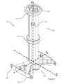
図1は、水底(図示せず)に係留された潮汐タービンアセンブリ150を示す。潮汐タービンアセンブリ150は、浮力があり、実質的に剛性であり、アセンブリが水面で浮くことができるようにするべく船体によって封入された本体152を備える。アセンブリ150は、便宜上マークされたx軸及びz軸を有する側面図から示されており、この場合、矢印はその軸の正の方向を指す。y軸は、x軸及びz軸の両方に垂直である(したがって、画像の平面にも垂直である)。アセンブリ150の後部又は船尾(負のx方向)に向かって、タービン展開モジュール154が、水中から又は水中に1つ以上のタービン158を上昇及び下降させるために配置される。タービン158は、ビーム156の遠位端に装着され、ビーム156は、タービン展開モジュール154によって駆動されて水中から上方に揺動し、水中からタービン158を上昇させることができる。これは、アセンブリ150の喫水を低減して、設置場所への又は設置場所からのアセンブリ150の輸送を容易にするのを助けることができる。他の例では、荒海による損傷を防止するために又はタービン158を修理もしくは検査するために、タービン158を水中から上昇させることができる。いずれの場合でも、発電を開始することができるように(場合によっては、発電を再開する)、タービン158を水中に、例えば船体の下に揺動させて戻すために、タービン展開モジュール154によって逆作用を引き起こすことができる。FIG. 1 shows a
タービンアセンブリ150の前部又は船首(正のx方向)に向かって、係留システムの一部を形成するタレット100がある。タレット係留システムは、潮汐タービンアセンブリ150に固定されるシャフト102を備える。シャフト102は、タレット100と潮汐タービンアセンブリ150との間の相対的な回転動作を可能にするように、潮汐タービンアセンブリ150に装着される。シャフト102の下端部(z軸負方向)にはチェーンテーブル104が固定される。チェーンテーブル104及びシャフト102の動作は、両方とも略剛性構造であり、チェーンテーブル104及びシャフト102の一方の回転及び垂直運動がチェーンテーブル104及びシャフト102の他方の同じ動作を引き起こすように互いに結合される。Towards the front or bow (positive x-direction) of the
上流側係留ライン106及び下流側係留ライン108は、それぞれの上流側及び下流側固定ポイント(図示せず)でチェーンテーブル104を水底に結合する。チェーンテーブル104は、係留ライン106,108が水底に対するチェーンテーブル104の回転に抵抗するように水底に固定される。これは、シャフト102、実際にはタレット100全体が、水底の上方の適所に保持され、係留ライン106,108の張力によって回転することが防止されることを意味する。タレット100をこのように強固に保持することにより、例えば変化する局所的な流れに適応するために、潮汐タービンアセンブリ150を水底に対して回転させることができる。An
特に、アセンブリ150は、潮汐が方向を変えると約180°ヨーイングする(z軸を中心に回転する)。また、タレット係留システム100は、潮汐流の方向が各サイクルで同じでない場合、例えば局所的な流れに起因して、タービン158を局所的な流れの流れベクトルとより良好に位置合わせするように、潮汐タービンアセンブリ150がその向きを調整できるようにする。これは、アセンブリ150を固定された向き又は姿勢でしっかりと保持することができる固定係留システムの改善であるが、そうすることで、流れ方向の変化に適応する能力を必然的に犠牲にする。In particular, the
潮汐タービンアセンブリ150は、流れが(正のx方向から負のx方向に)流れてタービン158を駆動するように、使用時に示されている。図には、このプロセスに関与する様々な力が示されている。特に、船体からの抗力、ビームからの抗力、及びタービン推力は、正味抗力負荷FDに組み合わされる。正味の抗力負荷は、抗力を支配するタービン推力に起因して、タービン158に非常に近い有効抗力中心から作用する。 The
重心はCoGとしてマークされ、潮汐タービンアセンブリ150の総質量Mは、CoGを通って下方に作用する。同様に、潮汐タービンアセンブリの浮力BAは、浮力の長手方向中心LCBを通って上方に作用する。なお、一般的にCoGとLCBは同一地点には位置しない。 The center of gravity is marked as CoG, and the total mass M of the
タレットにかかる力は、係留ライン106,108の張力によって加えられる下向きの力による正味の垂直係留負荷TZである。更に、係留ライン106,108の張力の水平成分に起因して、正味の水平係留負荷TXが存在する。明らかに、潮汐タービン装置150が所定の位置に留まり、沈まない場合、BA=M、及びTX=FDであり、これは、潮汐タービンアセンブリ150、タレット100、及び係留ライン106,108の慎重な設計によって容易に達成することができる。しかしながら、この制約は静的条件のみを満たす。水流がある場合、上記の力のみが作用すると、これらの力のそれぞれによって発生するモーメントを計算することができる。力は、一般に、浮力の長手方向中心を通過しないため、浮力の長手方向中心の周りで回転を引き起こす傾向がある。 The force on the turret is a net vertical mooring loadTZ due to the downward force exerted by the tension in the
時計回りの方向を正(正のz方向を最短円弧の正のx方向にマッピングする方向)とすると、これらのモーメントは以下の通りである。正味抗力FDはモーメントFD・z2を生じさせ、ここで、z2は正味抗力の有効作用点と浮力の縦方向中心との間の垂直オフセットである。潮汐タービンアセンブリ150の質量Mは、-M・x2のモーメントを与えるように作用し、ここで、x2は、重心と長手方向浮心との間の(x方向の)水平方向間隔である。 Taking the clockwise direction as positive (the direction that maps a positive z direction to the positive x direction of the shortest circular arc), these moments are: The net drag force FD produces a moment FD · z2 , where z2 is the vertical offset between the effective point of application of the net drag and the longitudinal center of buoyancy. The mass M of the
最後に、タレットは、TZ・x1-TXz1のモーメントを与え、ここで、x1は、タレット100と浮力の長手方向中心との間の(x方向の)水平方向の間隔であり、z1は、チェーンテーブル(具体的には、チェーンテーブル104と係留ライン106,108との間の接続の位置)と浮力の長手方向中心との間の垂直方向の間隔である。 Finally, the turret exerts a moment of TZ · x1 -TX z1 , where x1 is the horizontal spacing (in the x direction) between the
安定した配置(力のために回転しない配置)は、
本発明は、タレット100に更なるモーメントを与えることによってこの問題に対処する。具体的には、タレット100は、潮汐タービンアセンブリ150に上向きの力を与えるように構成される。幾つかの例では、これは所定の浮力であり、他の例では可変浮力である。また更なる例では、それはチェーンテーブル104上の流体力学的フェアリングであり、幾つかの例では、それはこれらのうちの2つ以上の組み合わせである。タレット100で上向きの力を加えると、モーメント方程式はΣimi=FDz2+(Tz-L-B)x1Txz1-Mx2に変化し、この場合、L及びBはそれぞれ流体力学的揚力及び浮力である。これらは、タービン158によって引き起こされるピッチング(y軸周りの回転)に抗するように選択することができる。特に、LとFDの両方は流速によって変化するため、流体力学的表面は、タービン推力によって引き起こされるピッチングモーメントを動的に打ち消すLを与えるように設計することができる。浮力は、モーメントのバランスを微調整するために、更なる時変力を与えるように可変であり得る。言い換えると、タレット100で上向きの力を加えることにより、潮汐タービンアセンブリ150の向きを変えることができ、安定した配置をもたらすことができる。特に、安定した配置を平坦な向きに近づけることができる(船首-船尾線は広く水平である)。 The present invention addresses this problem by providing an additional moment to the
図1には詳細に示されていないが、タレット100は、潮汐タービン装置150に対して垂直に摺動するように構成されてもよい。これは、z1距離、したがってタレット100によって生成される係留荷重のx成分に起因するモーメントの大きさを変更することによって、装置150の安定位置の更なる調整を可能にすることができる。また、この垂直動作は、アセンブリ150を設置場所に輸送しながらタレット100を上昇させることによって、アセンブリ150を設置場所に輸送しながらアセンブリ150の喫水を低減するのに有用となり得る。これにより、輸送プロセスの効率に影響を与えることなく、乾燥地又はドックもしくは港湾の比較的穏やかな水域でタレット100をアセンブリ150に設置することが可能になる。アセンブリ150が設置場所に到着した時点で、係留ライン106,108を使用してタレット100を水底に固定することができる。他の例において、タレット100は、アセンブリ150が設置場所に到着する前に水底に固定することができる。 Although not shown in detail in FIG. 1 , the
また、図1には、タービン158によって生成された電力を沿岸に伝送することを可能にする電力伝送装置も詳細には示されていない。この構成は、タービンアセンブリ150とタレット100との間にスリップリングを含み、それにより、タレット100とアセンブリ150との間の回転接続を介してタレット100に電力を安全に伝達することができる。電力は、係留ライン106,108に沿って延びるライザケーブル(図示せず)によって沿岸に伝送され、水底に沿って沿岸まで延びることができる。1つ以上のスリップリングを使用して、必要に応じてタレットへの制御信号の送信を制御することもできる。或いは、アセンブリ150とタレット100との間の制御信号に短距離無線通信を使用することができる。Also not shown in detail in FIG. 1 is a power transmission arrangement that allows the power generated by the
図1はこれを詳細に示していないが、場合によっては、タレット100は、シャフト102の長さの少なくとも一部にわたってアセンブリ150に対して垂直(又はz)方向に摺動可能であってもよい。そのような場合、摺動動作は、タレット100をアセンブリ150に対して所定の高さに維持できるようにするべく選択的にロック可能である。本明細書の他の箇所で述べたように、タレット100は、アセンブリ150に上向きの力を付与するように構成することができる。ロック機構(図示せず)は、ロック機構がロックされているときに、そのような上向きの力が加えられても、力がアセンブリ150に完全に伝達されるように、タレット100とアセンブリ150との間の相対動作に抵抗するのに十分な強度を有する。1 does not show this in detail, in some cases, the
ここで図2を参照すると、タレット100は、潮汐タービンアセンブリ150に装着された状態で、より詳細に示されている。前述のように、タレット100に作用する力L及びBが示されており、それぞれタレット100の流体力学的揚力効果及び浮力を表わす。力T1は上流側係留ライン106の張力を表わし、T2は下流側係留ライン108の張力を表わす。これらは、x(水平)及びz(垂直)成分T1x,T1z,T2X,T2Zに分解される。係留ラインは、取り付けポイント128でチェーンテーブル104に結合する。また、図には、タレットの質量Mに起因する重量も示されている。 2, the
潮汐タービンアセンブリ150は、タレット100を受け入れるための円筒形の装着開口部を有する。タレット100は、円筒形装着開口部の内面と係合するための上側ラジアルベアリング110及び下側ラジアルベアリング112を有する。各ラジアルベアリング110,112は、タレット100と潮汐タービンアセンブリ150との間の相対回転動作を可能にするように配置される。しかしながら、前述した様々な力は、タレット100とタービンアセンブリ150との間の摩擦力をもたらす。特に、上側ラジアルベアリングは、径方向反力R1x及び垂直反力R1zを有し、下側ラジアルベアリングは、径方向反力R2xを有する。これらの反力の摩擦係数は、それぞれμ1x、μ1z及びμ2xと表される。 The
反力の正味の効果は、図2にQFとして表わされる摩擦トルクを与えることである。実際には、これは、アセンブリ150がタレット100に対して回転し、それによって意図されたヨーイング効果を達成するために、タレット100とタービンアセンブリ150との間に加えられなければならないトルクである。半径r(ラジアルベアリングがタービンアセンブリ150に接触する有効半径)を有するタレット100では、摩擦トルクはQF=r・(μ1zR1z+μ1xR1x+μ2xR2x)と完全に記載されている。 The net effect of the reaction forces is to provide a friction torque, represented in Figure 2 asQF . In effect, this is the torque that must be applied between the
ラジアルベアリング110,112は、摩擦を可能な限り低減するように設計することができるが、これは、本システムにとって限定的な利益である。これは、潮汐タービンアセンブリ150の双方向性と、潮汐が低く正味流れがないときにヨーイング作用が起こるという事実とに起因する。理想的なシステムの弛慢な干潮汐では、T1=T2であるため、R1x=R2X=0であり、これは摩擦力への支配的な寄与が垂直成分に起因することを意味する。具体的には、潮流が流れていないときの揚力Lを0とすると、摩擦トルクは、QF=r・μ1z・R1z=r・μ1z・(T1z+T2z-B)となる。言い換えると、所定の浮力が各係留ライン106,108の張力の垂直成分の合計に等しい上向きの力を生成する場合、弛弛干潮時の摩擦トルクは最小であり、タレット100とアセンブリ150との間の回転に対するインピーダンスも最小である。したがって、所定の浮力は、アセンブリ150がタレット100の周りを回転できないという問題に直接対処する。もちろん、潮汐変化中に潮流が全く流れない期間は比較的短い。そのような場合、結果として生じる摩擦力が最小になるようにするために解析に考慮することができる流体力学的揚力Lが存在する。浮力及び揚力は、当然ながら、前述のピッチング力に抗する効果も有する。 Although the
また、図2は、揚力Lを与えるための流体力学的表面126を示す。より具体的には、流体力学的表面126は、チェーンテーブル104上のフェアリングとして形成される。他の場合には、流体力学的表面は、これに加えて又は代えて、適度に小さいタレット100を保持しながら揚力を増大するために、チェーンテーブル104を越えて延びる部分、例えばチェーンテーブル104からy方向に延びる細長いウィング型構造を含むことができる。2 also shows a
図2では、流体力学的表面126は、水が表面上をいずれかの方向に流れるときに揚力が生成されるという意味で双方向である。より具体的には、表面126は対称であり、所定の流速で生成される揚力は、水が正又は負のx方向に流れているかどうかにかかわらず同じであることを意味する。これは、フェアリング126がピッチングモーメントに抗する上記の効果が、潮汐の出入りにかかわらず存在するように配置できることを意味する。他の例では、流体力学的表面が反対方向の流れに応じて異なる挙動をすることが有益であり得る。浮力要素(前述の所定の又は可変の浮力を与えるための要素)をフェアリング126内に配置することができ、これは、浮力要素を損傷から保護することができ、浮力が水中空気ポケットに基づく場合、フェアリングは、空気を水中に保持するための外側エンベロープを与えることができる。In FIG. 2, the
ここで図3を考える。ここでは、明確にマークされたx、y、及びz軸と共にタレットの詳細図を見ることができる。チェーンテーブル104は、一般に剛性であり、以下でより詳細に説明するように、チェーンテーブル104の四隅に配置された、係留ラインをチェーンテーブル104に結合するための4つの取り付けポイント128を有する。剛性チェーンテーブル104は、取り付けポイント128を離間して保持し、この場合、上流側及び下流側の取り付けポイント128の対は、x方向に互いに離間して保持される。更に、取り付けポイント128の各対(上流側の対及び下流側の対)は、y方向に互いに離間した2つの取り付けポイント128を含む。Now consider FIG. 3, where a detailed view of the turret can be seen with clearly marked x, y, and z axes. The chain table 104 is generally rigid and has four
シャフト102は、外側ケーシングによって囲まれた一群のパイプ122から形成されているように見える。これは、強固なシャフト102を形成する安価で容易な方法を提供した。パイプ122及び外側ケーシング124の一般的な構成は、タレット100の抗力を低減するように配置され得る。図示の例において、外側ケーシング124は、シャフト102を合理化するために、x方向に沿って(すなわち、流れの方向に沿って)狭い角度で平面図で広く菱形である。また、パイプ122自体は、チェーンテーブル104とアセンブリ150との間を連通するための便利な手段も与える。例えば、チェーンテーブル104が可変浮力要素を含む場合、浮力は、この目的に適合させることができるパイプ122のうちの1つを介してチェーンテーブル104内に空気を送り込むことによって調整することができる。The
これに加えて又は代えて、別個のパイプ122を使用して、タービン158によって生成された電力をアセンブリ150から沿岸に運び、チェーンテーブルから/チェーンテーブルに、及び/又は沿岸へと/から前方に、タービンアセンブリ150へ/タービンアセンブリ150から通信メッセージを運ぶことができる。幾つかの例において、沿岸とアセンブリとの間の通信は、沿岸からタービンアセンブリ150の動作の様々な態様の制御を可能にすることができ、例えば、荒海での損傷を防止するためにタービン158を水中から上昇させることができ、これは、海が非常に荒く、ボート又は空気によってアセンブリ150の設定又は配置を変更するためにアセンブリ150に物理的に対応することが非実用的又は非安全である場合に有利であり得る。Additionally or alternatively,
ここで図4を参照すると、係留ラインに連結された図3のタレット100が平面図で示されている。図4は、図の下部に1つの係留ラインのみを示しているが、完全な係留システムは、2つの係留ライン(例えば図1及び図2に示すように)を含むことに留意されたい。図4に示す係留ラインは、図1及び図2に示す係留ライン106,108のうちの1つに対応する。Referring now to FIG. 4, the
図4は、チェーンテーブル104に結合された係留ラインを示す。係留ラインは、下端部で水底上の固定ポイント114に結合するための第1の部分116を有する。第1の部分は、その上端部が係留索120に接続する。係留索120は、3つの取り付けポイントを有し、そのうちの1つが第1の部分116に接続される。係留索120上の残りの2つの取り付けポイントは、係留ラインの第2の部分118に結合する。係留ラインの第2の部分118は、平行な荷重経路を与える2本のラインを含み、これらのラインは、係留索120から分岐してチェーンテーブル104上の2つの取り付けポイント128に結合する。言い換えると、係留ラインは、上端部で2つの取り付け部へと二股になるが水底上の単一のポイント114に固定されるという意味で、二股係留ラインである。Figure 4 shows a mooring line coupled to the chain table 104. The mooring line has a
係留ラインの第2の部分118が結合される2つの取り付けポイント128は、y方向に離間している。これにより、単一の係留ラインは、チェーンテーブル104上の単一の取り付けポイント128で可能であるよりも、水底に対するタレット100の回転に対するより大きな抵抗を与えることができる。一例として、水底に対する図4に示すタレット100の回転を考える。タレット100が回転する方向にかかわらず、第2の部分118の二本の分岐ストランドの一方又は他方は張力を受ける。これは、タレット100の両方向の回転が係留システムによって抵抗されることを意味する。一例として、係留ラインは、取り付けポイント128間のy軸間隔が約1メートルでチェーンテーブル104に接続することができ、これは、殆どの場合、所望の効果を達成するのに十分な間隔であることが分かっている。他の例では、間隔は、想定される具体的な実施態様に応じて、より大きくても小さくてもよい。The two
係留ラインの第1の部分116はチェーンとして形成され、これにより強い結合をもたらすことができる。係留ラインの第2の部分118は、アラミド繊維線、例えばDyneema(RTM)などの低質量合成材料から形成される。これにより、必要な張力負荷に耐える適切な材料からラインを作ることができるが、チェーンテーブル104に過度の質量を導入することはない。二股部(すなわち、図4の係留索120)の位置は、タレット100に比較的近い(確実に、係留索が取り付けポイント114よりもタレット100に近い)ように示されている。殆どの場合、係留索120又は二股部は、タレット100から、具体的にはチェーンテーブル104上の取り付けポイント128から離れて係留ラインの全長の10%以下に配置されるべきである(すなわち、水底上の固定ポイント114から測定された係留ラインの長さの90%以上)。The
より詳細には、係留ラインの第1の部分116は、チェーンであり、重く、タレット100に復元力を与える。これは、張力T1及びT2がそれぞれの係留ライン106,108の重量からの寄与を含む図2を参照すると最もよく分かる。係留ラインに二股部を設けることにより、この張力が2つの取り付けポイント128の間に分散される。この結果、タレットには平衡位置が存在し、係留ラインの第2の部分118の2本の分岐ストランドのそれぞれの張力がタレット100で(図3に見えるタレット100の対称性に起因して、その回転軸の周りに)等しい反対の回転モーメントを引き起こし、したがってトルクのバランスをとり、回転を引き起こさない。2つの分岐ストランドの長さが等しい場合、平衡位置は図4に示す位置になる。 More specifically, the
具体的には、図4に示す平衡位置は、係留ラインの第1の部分116の方向(x-y平面内)に引かれた第1の線が、チェーンテーブル140に達するまで延長される平衡位置である。この第1の線は、2つの取り付けポイント128の間に引かれた第2の線と直角に交わる。図4では、タレット100を任意の一方向に回転させると、2つの分岐ストランドの一方の張力が増加し、他方のストランドが弛弛し、張力が減少することが明確に分かる(場合によっては劇的に、更には実質的に0になる)。明確にするために、図4に示すように、タレット100の時計回りの回転は、2本のストランドの左側の張力を増加させ、一方、右側のストランドの張力は劇的に減少し、逆もまた同様である。Specifically, the equilibrium position shown in FIG. 4 is one in which a first line drawn in the direction of the
図4の二股係留ラインは、設置の改善された単純さ(例えば、設置されるべき水底上のアンカーポイントの数の半分を必要とする)とは全く別に、それぞれが水底上の異なるそれぞれのポイントに結合された一対の独立した単一の係留ラインに優る利点を有する。一般に、独立した係留ラインでは、ラインが適度に弛んでいる場合、各取り付けポイント128に異なる大きさの張力を与える。これは、各ラインの弛みがそのラインの張力に影響を及ぼし、したがって、水底上の固定ポイント114に対するタレット100の位置(例えば、波又は流れの動きの下でのドリフトに起因する)が、2つの係留ライン間の張力差、したがって水底に対するタレット100の回転を引き起こす可能性があるためである。したがって、直感に反して、このタスクのために2つの独立した係留ラインを使用することは、係留システムが防止しようとするまさにその回転をもたらすことができる。Quite apart from the improved simplicity of installation (e.g., requiring half the number of anchor points on the water bottom to be installed), the bifurcated mooring line of FIG. 4 has advantages over a pair of independent single mooring lines, each attached to a different respective point on the water bottom. In general, independent mooring lines, when the lines are moderately slack, provide different amounts of tension at each
対照的に、図4の二股係留ラインは、係留索120まで同じ張力を与え、これは、固定ポイント114及び係留索120の位置からの直線によって規定される軸に対するタレット100の回転のみが張力差を引き起こすことを意味する。その結果、係留システムは、タレット100を水底に対する回転に対して優先的に支持するので、二股係留システムは、タレット100をその意図された向きに保持することがより良好である。In contrast, the bifurcated mooring line of FIG. 4 provides the same tension all the way up to the
図示されていないが、チェーンテーブル104は、更なる取り付けポイント128を介して第2の係留ラインに接続可能である。第2の係留ラインは、第1の係留ラインと同じ形態とすることができ、同じ利点を有する。他の例では、第2の係留ラインは、チェーンテーブル104上に単一の取り付けポイント128のみを有する、より単純な形態であってもよい。これは、潮の流れが非対称である場合に可能であり、その結果、前述の絡み合いの問題は、一方の流れ方向で発生する可能性が最も高いが、他方の流れ方向では比較的発生しにくい。また、そのような設置場所は、ほぼ同じ理由で、非対称の流体力学的フェアリングを利用することができる。Although not shown, the chain table 104 can be connected to a second mooring line via a
チェーンテーブル104上に離間した取り付けポイント128を有するこの係留システムは、水底に対するタレット100の回転に対してより強い抵抗をもたらす。単独で又は前述のシステム(タレット100での上向きの力が摩擦を低減する)と組み合わせて、これは、タレット100が強固に保持されるため、係留ライン106,108の絡まりが発生する可能性を低減する。実際に、組み合わせて、(二股係留ライン構成に起因して)タレット100と潮汐タービンアセンブリ150との間に及ぼされるトルクを増加させる効果と、(タレット100によってもたらされる上向きの力に起因して)摩擦を減少させる効果とは、両方とも、流れが方向を変えるときに潮汐タービンアセンブリ150がタレット100に対して回転するようにし、それによって絡まりを減少させるという共通の目標に向かって働く。This mooring system, with spaced attachment points 128 on the chain table 104, provides more resistance to rotation of the
図5及び図6は、斜視図及び平面図でそれぞれタレット100の別の形態を示す。図5及び図6は、図3及び図4と概ね同等であり、共通の特徴については再度詳細には説明しない。しかしながら、図5及び図6では、フェアリング126がなく、チェーンテーブル104の内部構造が見える。特に、図3及び図4と図5及び図6との比較は、チェーンテーブル104の容積(フェアリング126の内側の領域)の大部分が浮力要素を格納するために利用可能であることを示している。更に、図5及び図6に示す形態は、本明細書の開示の一部として示すように使用することができ、具体的には、係留ラインのための取り付けポイント128は、y方向に離間しており、これは、前述したように絡み合いの発生を低減するのを助けることができる。場合によっては、係留ラインによってもたらされる効果は非常に強くなる可能性があるため、浮力又は流体力学的揚力によってもたらされる更なる効果は必要ない。5 and 6 show another form of the
上記に見られるように、本出願は、一般にここで要約される多くの有利な特徴を説明する。第1に、タレット係留式潮汐タービン装置へのチェーンテーブルの特定の適合は、タレットが水底に対する回転に抵抗することができるという意味でより安定性の高いシステムを可能にし、それによって実際のタービンアセンブリが回転して局所的な潮流の流れと整列することを可能にする。As seen above, the present application describes a number of advantageous features which are generally summarized herein. Firstly, the specific adaptation of the chain table to the turret-tethered tidal turbine device allows for a more stable system in the sense that the turret can resist rotation relative to the bottom, thereby allowing the actual turbine assembly to rotate and align with the local tidal currents.
この効果は、浮体構造、特に浮体タービン構造では、大きな喫水及び抗力(タービンが表面下にあるため)に起因して達成することが特に困難である。前述したように、これにより、タレットがタービン装置でねじられ、係留ラインのねじれを引き起こす可能性がある。更に、タービンが係留ライン自体の中へと旋回され、タービン、係留ライン、又はその両方を損傷する危険性がある。This effect is particularly difficult to achieve on floating structures, especially floating turbine structures, due to the large draft and drag forces (as the turbines are below the surface). As mentioned above, this can cause the turret to twist on the turbine installation, causing kinking of the mooring lines. Furthermore, there is a risk that the turbine will be swung into the mooring lines themselves, damaging the turbine, the mooring lines, or both.
タレット係留システムを潮汐タービンアレイに適用する場合、一方では係留システムの複雑さを低減すること(特に、水底上のアンカーポイントをより少なくすること)により、設置コストが節約され、装置が変化する潮流の中で旋回するときにタービンの動きを妨げる水中障害物が少なくなるというジレンマが生じる。一方、係留ラインが少ないと、タレットがそれ自体を水底に対して回転可能に固定することができず、係留ラインの絡まり及びねじれをもたらす可能性が高くなる傾向がある。When applying turret mooring systems to tidal turbine arrays, a dilemma arises: on the one hand, reducing the complexity of the mooring system (particularly having fewer anchor points on the water bottom) saves on installation costs and provides fewer underwater obstacles to impede turbine movement as the device turns in changing tides. On the other hand, fewer mooring lines tend to prevent the turret from being able to rotatably secure itself to the water bottom, increasing the likelihood of tangling and twisting of the mooring lines.
本出願は、チェーンテーブル上の離間した取り付けポイントが(水底に対して)増加した回転抵抗を与えるのに役立つ解決策を提示する。この効果は非常に顕著であり、係留ラインがチェーンテーブルなどのタレットの比較的小さな領域に連結される場合であっても、2つの二股係留ライン、すなわち上流側係留ライン及び下流側係留ラインのみを使用して、このように潮汐タービンアセンブリを固定することができる。この効果は、係留システムの一部としてケーブル又はチェーンのみを使用して達成することができる。言い換えると、チェーンテーブル以外に、係留システムは、剛性ブレース要素を殆ど完全に含まなくてもよく、これはコスト及び複雑さの更なる節約に相当する。The present application presents a solution where spaced attachment points on the chain table help to provide increased rotational resistance (relative to the water bottom). This effect is so significant that the tidal turbine assembly can be secured in this way using only two bifurcated mooring lines, i.e. an upstream mooring line and a downstream mooring line, even when the mooring lines are connected to a relatively small area of the turret such as the chain table. This effect can be achieved using only cables or chains as part of the mooring system. In other words, other than the chain table, the mooring system may be almost completely free of rigid bracing elements, which represents a further savings in cost and complexity.
別の有利な態様は、上向きの力を与えるタレット及び/又はチェーンテーブルを提供することである。それは、係留ラインを支持するための位置を与えるだけでなく(全てのタレット係留に自明に当てはまるように)、タービンアセンブリ自体に上向きの力を与える。言い換えると、タレットが単独で浮く(アセンブリから取り外される)平衡深さは、タービンアセンブリに取り付けられたときにタレットが平衡状態で浮く深さよりも高い。Another advantageous aspect is to provide a turret and/or chain table that provides an upward force. It not only provides a location for supporting the mooring lines (as is trivially true for all turret moorings), but also provides an upward force on the turbine assembly itself. In other words, the equilibrium depth at which the turret floats alone (removed from the assembly) is higher than the depth at which the turret floats in equilibrium when attached to the turbine assembly.
この特徴により、タレットは、現在展開されているときにタービンが受ける大きな推力に起因して生じるアセンブリのピッチングモーメントに抗することができる。更に、タレットからの上向きの力は、タービンからの変化する推力に起因する可変ピッチング動作に抗するように可変であり得る。この上向きの力の変化は、浮力、流体力学的表面の使用、又はその両方を調整することによって(又は実際には完全に他の方法によって)達成することができる。これにより、アセンブリ全体の姿勢を制御することができ、安定性を提供することができる。This feature allows the turret to resist pitching moments on the assembly resulting from the large thrust forces experienced by the turbines when currently deployed. Additionally, the upward force from the turret can be varied to resist the variable pitching motion resulting from the varying thrust from the turbines. Varying this upward force can be achieved by adjusting buoyancy, the use of hydrodynamic surfaces, or both (or indeed by other methods entirely). This allows the attitude of the entire assembly to be controlled, providing stability.
これは、殆どのタレット係留装置がそのような強い可変推力を経験しないため、潮汐タービンアセンブリに非常に特有の問題である。これは、殆どのタレット係留システムが、可変力はもちろんのこと、上向きの力を生成するタレットを全く必要としないことを意味し、そうすることにより、実際にそれらのシステムを不安定にし、又はアセンブリの望ましくないピッチング又は傾斜を引き起こす。This is a very particular problem for tidal turbine assemblies because most turret moorings do not experience such strong variable thrust forces. This means that most turret mooring systems do not need a turret to generate an upward force at all, let alone a variable force, and by doing so would actually destabilize those systems or cause undesirable pitching or tilting of the assembly.
Claims (20)
Translated fromJapaneseタレットであって、
前記潮汐タービンアセンブリに装着するため及び回転軸を中心とした前記タレットと前記潮汐タービンアセンブリとの間の相対的な動作を可能にするためのシャフトと、
前記シャフトの下端部に固定されるチェーンテーブルとを有するものと、
水底上の単一の上流側固定ポイントを前記チェーンテーブルの上流側部分に結合するための上流側係留ラインと、
水底上の単一の下流側固定ポイントを前記チェーンテーブルの下流側部分に結合するための下流側係留ラインと、を備え、
前記上流側係留ラインは、前記チェーンテーブルの前記上流側部分上の2つの離間した上流側取り付けポイントに結合するための二股係留ラインであり、
前記下流側係留ラインは、前記チェーンテーブルの前記下流側部分上の2つの離間した下流側取り付けポイントに結合するための二股係留ラインであり、
前記タレットは、前記チェーンテーブルが水中に浸漬されるときに上向きの力を与えるように構成され、
上向きに凸形状の湾曲面を有する流体力学的フェアリングが、前記チェーンテーブル上に設けられ、
前記上向きの力は、前記流体力学的フェアリングによって与えられ、
前記シャフトは、前記潮汐タービンアセンブリと係合するための上側ラジアルベアリング及び下側ラジアルベアリングを含み、
前記タレットは、前記潮汐タービンアセンブリに対して垂直方向で摺動可能である
タレット係留システム。 1. A turret mooring system for a tidal turbine assembly, comprising:
A turret,
a shaft for mounting to the tidal turbine assembly and for enabling relative movement between the turret and the tidal turbine assembly about an axis of rotation;
a chain table fixed to a lower end of the shaft;
an upstream mooring line for connecting a single upstream fixed point on the water bottom to the upstream portion of the chain table;
a downstream mooring line for connecting a single downstream fixed point on the water bottom to the downstream portion of the chain table;
the upstream mooring line being a bifurcated mooring line for coupling to two spaced apart upstream attachment points on the upstream portion of the chain table;
the downstream mooring linebeing a bifurcated mooring line for coupling to two spaced apart downstream attachment points on the downstream portion of the chain table;
the turret is configured to provide an upward force to the chain table when the chain table is immersed in water;
a hydrodynamic fairing having an upwardly convex curved surface is provided on the chain table;
the upward force is provided by the hydrodynamic fairing;
the shaft including upper and lower radial bearings for engagement with the tidal turbine assembly;
The turret is vertically slidable relative to the tidal turbine assembly.
Turret mooring system.
前記下流側係留ラインは、海底上の前記下流側固定ポイントを係留索に結合するための第1の部分と、前記係留索を前記チェーンテーブルの前記下流側部分上の2つの下流側取り付けポイントに結合するための第2の部分とを有する
請求項1に記載のタレット係留システム。 the upstream mooring line having a first portion for connecting the upstream fixed point on the seabed to a mooring line and a second portion for connecting the mooring line to two upstream attachment points on the upstream part of the chain table; and/or
2. The turret mooring system of claim 1, wherein the downstream mooring line has a first portion for connecting the downstream fixed point on the seabed to a mooring line and a second portion for connecting the mooring line to two downstream attachment points on the downstream portion of the chain table.
請求項1又は2に記載のタレット係留システム。 3. The turret mooring system of claim1 or 2 , wherein the upward force is provided by a buoyant element in the water.
請求項3に記載のタレット係留システム。 The turret mooring system of claim3 , wherein the element has variable buoyancy.
請求項1から4のいずれか一項に記載のタレット係留システム。5. The turret mooring system of claim 1, wherein the hydrodynamic fairing is shaped to resist anticipated pitching moments on the tidal turbine assembly due to drag forces acting on the turbine.
タレットを備え、前記タレットは、前記潮汐タービンアセンブリに装着するため及び回転軸を中心とした前記タレットと前記潮汐タービンアセンブリとの間の相対的な動作を可能にするためのシャフトと、前記シャフトの下端部に固定されるチェーンテーブルとを有し、
前記タレットは、前記チェーンテーブルが水中に浸漬されるときに上向きの力を与えるように構成され、
上向きに凸形状の湾曲面を有する流体力学的フェアリングが、前記チェーンテーブル上に設けられ、
前記上向きの力は、前記流体力学的フェアリングによって与えらる
タレット係留システム。 1. A turret mooring system for a tidal turbine assembly, comprising:
a turret having a shaft for mounting to the tidal turbine assembly and for enabling relative movement between the turret and the tidal turbine assembly about an axis of rotation, and a chain table fixed to a lower end of the shaft;
the turret is configured to provide an upward force to the chain table when the chain table is immersed in water;
a hydrodynamic fairing having an upwardly convex curved surface is provided on the chain table;
The upward force is provided by the hydrodynamic fairing.
Turret mooring system.
請求項6に記載のタレット係留システム。 The turret mooring system of claim6 , wherein the upward force is provided by a buoyant element in the water.
請求項7に記載のタレット係留システム。 The turret mooring system of claim7 , wherein the element has variable buoyancy.
請求項8に記載のタレット係留システム。 The turret mooring system of claim8 , wherein the hydrodynamic fairing is shaped to resist pitching moments expected on the tidal turbine assembly due to drag forces acting on the turbine.
請求項6から9のいずれか一項に記載のタレット係留システム。 10. A turret mooring system as claimed in any one of claims 6 to 9, wherein an upstream portion of the chain table is configured to couple to a single upstream fixed point on the water bottom via an upstream mooringline and a downstream portion of the chain table is configured to couple to a single downstream fixed point on the water bottom via adownstream mooring line.
請求項10に記載のタレット係留システム。 The turret mooring system of claim10 further comprising the upstream and downstream mooring lines.
前記下流側係留ラインは、前記チェーンテーブルの前記下流側部分上の2つの離間した下流側取り付けポイントに結合するための二股係留ラインである
請求項10又は11に記載のタレット係留システム。 the upstream mooring line is a bifurcated mooring line for coupling to two spaced apart upstream attachment points on the upstream portion of the chain table; and/or
12. A turret mooring system as claimed in claim10 or11 , wherein the downstream mooring line is a bifurcated mooring line for coupling to two spaced apart downstream attachment points on the downstream portion of the chain table.
前記下流側係留ラインは、海底上の前記下流側固定ポイントを係留索に結合するための第1の部分と、前記係留索を前記チェーンテーブルの前記下流側部分上の2つの下流側取り付けポイントに結合するための第2の部分とを有する
請求項11又は12に記載のタレット係留システム。 the upstream mooring line having a first portion for connecting the upstream fixed point on the seabed to a mooring line and a second portion for connecting the mooring line to two upstream attachment points on the upstream part of the chain table; and/or
13. The turret mooring system of claim 11 or 12, wherein the downstream mooring line has a first portion for connecting the downstream fixed point on the seabed to a mooring line and a second portion for connecting the mooring line totwo downstream attachment points on thedownstream portion of the chain table.
請求項6から13のいずれか一項に記載のタレット係留システム。 A turret mooring system as claimed in any one of claims6 to13 , wherein the shaft includes upper and lower radial bearings for engagement with the tidal turbine assembly.
前記タレットは、前記潮汐タービンアセンブリに対して垂直方向で摺動可能である
請求項1から14のいずれか一項に記載のタレット係留システム。 the turret is attached to the tidal turbine assembly;
The turret mooring system of any one of claims 1 to14 , wherein the turret is vertically slidable relative to the tidal turbine assembly.
(i)前記潮汐タービンアセンブリを設置場所に輸送するステップと、
(ii)前記タレットの前記チェーンテーブルの上流側部分を水底に対して単一の上流側固定ポイントで結合するとともに、前記タレットの前記チェーンテーブルの下流側部分を水底に対して単一の下流側固定ポイントで結合するステップと、
(iii)前記タレットを前記潮汐タービンアセンブリに固定するステップと
を含む方法。 16. A method of mooring a tidal turbine assembly to a water bottom using a turret mooring system according to any one of claims 1 to15 , comprising the steps of:
(i) transporting the tidal turbine assembly to an installation site;
(ii) connecting an upstream portion of the chain table of the turret to the bottom of the water at a single upstream fixed point and connecting a downstream portion of the chain table of the turret to the bottom of the water at a single downstream fixed point;
(iii) securing the turret to the tidal turbine assembly.
請求項16に記載の方法。17. The method of claim 16 , wherein step (iii) is performed before steps (i) and (ii), and step (iii) is performed at a dock or on land.
請求項17に記載の方法。 18. The method of claim 17, wherein upon completion of step (iii), the turret is vertically slidable relative to the tidal turbine assembly between a raised position and a lowered position, such that the tidal turbine assembly has a greaterdraft when the turret is in the lowered position than when the turret is in the raised position.
請求項18に記載の方法。 20. The method of claim18 , wherein during step (i) the turret is in a raised position.
前記タレットの垂直位置は、輸送中に前記潮汐タービンアセンブリのピッチを制御するためにステップ(i)の前又は最中に調整される、
請求項16から19のいずれか一項に記載の方法。 the turret is configured to provide an upward force when the chain table is submerged in water and the turret is vertically slidable;
The vertical position of the turret is adjusted before or during step (i) to control the pitch of the tidal turbine assembly during transport.
20. The method according to any one of claims16 to19 .
Applications Claiming Priority (3)
| Application Number | Priority Date | Filing Date | Title |
|---|---|---|---|
| GB1919097.4 | 2019-12-20 | ||
| GB1919097.4AGB2590508B (en) | 2019-12-20 | 2019-12-20 | Improved turret mooring system |
| PCT/GB2020/053307WO2021123825A1 (en) | 2019-12-20 | 2020-12-18 | Improved turret mooring system |
Publications (3)
| Publication Number | Publication Date |
|---|---|
| JP2023506893A JP2023506893A (en) | 2023-02-20 |
| JPWO2021123825A5 JPWO2021123825A5 (en) | 2023-12-13 |
| JP7705399B2true JP7705399B2 (en) | 2025-07-09 |
Family
ID=69322609
Family Applications (1)
| Application Number | Title | Priority Date | Filing Date |
|---|---|---|---|
| JP2022536977AActiveJP7705399B2 (en) | 2019-12-20 | 2020-12-18 | Improved Turret Mooring System |
Country Status (9)
| Country | Link |
|---|---|
| US (1) | US12409912B2 (en) |
| EP (1) | EP4077116A1 (en) |
| JP (1) | JP7705399B2 (en) |
| KR (1) | KR20220117298A (en) |
| AU (1) | AU2020410192A1 (en) |
| CA (1) | CA3162462A1 (en) |
| GB (1) | GB2590508B (en) |
| PH (1) | PH12022551461A1 (en) |
| WO (1) | WO2021123825A1 (en) |
Families Citing this family (1)
| Publication number | Priority date | Publication date | Assignee | Title |
|---|---|---|---|---|
| US12234800B2 (en)* | 2022-08-26 | 2025-02-25 | Kamil Podhola | Offshore floater system |
Citations (2)
| Publication number | Priority date | Publication date | Assignee | Title |
|---|---|---|---|---|
| WO2018154313A1 (en) | 2017-02-23 | 2018-08-30 | Sustainable Marine Energy Limited | Turbine system and mooring systems |
| JP2019512643A (en) | 2016-03-07 | 2019-05-16 | トカルド タイダル パワー ビー.ヴイ.Tocardo Tidal Power B.V. | A device that converts kinetic energy of horizontally flowing water into other types of energy |
Family Cites Families (13)
| Publication number | Priority date | Publication date | Assignee | Title |
|---|---|---|---|---|
| DE3344116A1 (en)* | 1983-12-07 | 1985-06-20 | Blohm + Voss Ag, 2000 Hamburg | ANCHORING AND TAKEOVER SYSTEM FOR LIQUID AND GASEOUS MEDIA ON A SHIP END OF A TANKER |
| NO171628C (en)* | 1987-10-12 | 1993-04-14 | Pusnes As | ROTARY HEAD |
| US5476059A (en)* | 1994-12-20 | 1995-12-19 | Imodco, Inc. | Turret drive mechanism |
| NO310604B1 (en)* | 1996-06-13 | 2001-07-30 | Petroleum Geo Services As | Submersible detachable bow |
| US6126501A (en)* | 1999-09-15 | 2000-10-03 | Nortrans Offshore(S) Pte Ltd | Mooring system for tanker vessels |
| US6698372B2 (en) | 2000-10-18 | 2004-03-02 | Fmc Technologies, Inc. | Turret mooring system and method for installation |
| US6484659B2 (en)* | 2001-03-20 | 2002-11-26 | Fmc Technologies, Inc. | Chain table arrangement and method for installation |
| US6990917B2 (en)* | 2001-12-28 | 2006-01-31 | Fmc/Sofec Floating Systems, Inc. | Large diameter mooring turret with compliant deck and frame |
| US7225749B2 (en)* | 2003-07-30 | 2007-06-05 | Sofec, Inc. | Turret mooring system for concrete hull vessel |
| GB0425303D0 (en)* | 2004-11-17 | 2004-12-15 | Overberg Ltd | Floating apparatus for deploying in a marine current for gaining energy |
| NO325261B1 (en)* | 2005-05-06 | 2008-03-17 | Norsk Hydro As | Anchorage arrangement for floating wind turbine installations. |
| US7451718B2 (en)* | 2007-01-31 | 2008-11-18 | Sofec, Inc. | Mooring arrangement with bearing isolation ring |
| CN106114762B (en)* | 2016-07-12 | 2018-08-28 | 中国船舶重工集团公司第七○二研究所 | Shallow water floating platform mooring gear and method |
- 2019
- 2019-12-20GBGB1919097.4Apatent/GB2590508B/enactiveActive
- 2020
- 2020-12-18KRKR1020227024685Apatent/KR20220117298A/enactivePending
- 2020-12-18JPJP2022536977Apatent/JP7705399B2/enactiveActive
- 2020-12-18CACA3162462Apatent/CA3162462A1/enactivePending
- 2020-12-18WOPCT/GB2020/053307patent/WO2021123825A1/ennot_activeCeased
- 2020-12-18AUAU2020410192Apatent/AU2020410192A1/enactivePending
- 2020-12-18USUS17/757,214patent/US12409912B2/enactiveActive
- 2020-12-18PHPH1/2022/551461Apatent/PH12022551461A1/enunknown
- 2020-12-18EPEP20838231.7Apatent/EP4077116A1/enactivePending
Patent Citations (2)
| Publication number | Priority date | Publication date | Assignee | Title |
|---|---|---|---|---|
| JP2019512643A (en) | 2016-03-07 | 2019-05-16 | トカルド タイダル パワー ビー.ヴイ.Tocardo Tidal Power B.V. | A device that converts kinetic energy of horizontally flowing water into other types of energy |
| WO2018154313A1 (en) | 2017-02-23 | 2018-08-30 | Sustainable Marine Energy Limited | Turbine system and mooring systems |
Also Published As
| Publication number | Publication date |
|---|---|
| EP4077116A1 (en) | 2022-10-26 |
| US20230002012A1 (en) | 2023-01-05 |
| WO2021123825A1 (en) | 2021-06-24 |
| US12409912B2 (en) | 2025-09-09 |
| PH12022551461A1 (en) | 2023-11-20 |
| GB2590508A (en) | 2021-06-30 |
| GB201919097D0 (en) | 2020-02-05 |
| GB2590508B (en) | 2021-12-22 |
| CA3162462A1 (en) | 2021-06-24 |
| JP2023506893A (en) | 2023-02-20 |
| AU2020410192A1 (en) | 2022-07-14 |
| KR20220117298A (en) | 2022-08-23 |
Similar Documents
| Publication | Publication Date | Title |
|---|---|---|
| US7541688B2 (en) | Floating apparatus for deploying in marine current for gaining energy | |
| KR101478397B1 (en) | Method and apparatus for towing offshore wind turbines | |
| EP2143629B1 (en) | Arrangement for stabilization of a floating foundation | |
| US20100326343A1 (en) | Mooring system for a tethered hydrokinetic device and an array thereof | |
| JP2011525877A (en) | A system for mooring floating plants that generate energy from water streams | |
| KR20190120785A (en) | Turbine Systems and Mooring Systems | |
| JP2019509934A (en) | Floating platform | |
| JP7705399B2 (en) | Improved Turret Mooring System | |
| JP2016055679A (en) | Tow device and tow method | |
| JP6786907B2 (en) | Attitude control system and attitude control method for underwater floating power generators | |
| JP2020026181A (en) | Mooring system | |
| JP6926932B2 (en) | Attitude control system for hydroelectric power generators | |
| GB2592170A (en) | Improved turret mooring system | |
| JP2020084764A (en) | Undersea floating type ocean current power generation device and undersea floating type ocean current power generation system | |
| JP6627292B2 (en) | Attitude control system and attitude control method for floating type underwater power generator | |
| WO2022049263A1 (en) | Floating body and mooring system | |
| JP6958073B2 (en) | Underwater floating device | |
| KR102034347B1 (en) | Tidal Current Power Generator Construction System Using Guide Wire | |
| JP2006123848A (en) | Swing reducing device for anchored floating structure | |
| JP2018202892A (en) | Attitude control system and attitude control method of underwater floating type-power generator | |
| JP6814606B2 (en) | Current power generator | |
| JP2024098196A (en) | Method and system for suspending weight | |
| KR20250032369A (en) | Additional floatage platform for loading working wind turbine | |
| CN118992038A (en) | Anti-rolling floating wind power device |
Legal Events
| Date | Code | Title | Description |
|---|---|---|---|
| A521 | Request for written amendment filed | Free format text:JAPANESE INTERMEDIATE CODE: A523 Effective date:20231205 | |
| A621 | Written request for application examination | Free format text:JAPANESE INTERMEDIATE CODE: A621 Effective date:20231205 | |
| A977 | Report on retrieval | Free format text:JAPANESE INTERMEDIATE CODE: A971007 Effective date:20241024 | |
| A131 | Notification of reasons for refusal | Free format text:JAPANESE INTERMEDIATE CODE: A131 Effective date:20241105 | |
| A601 | Written request for extension of time | Free format text:JAPANESE INTERMEDIATE CODE: A601 Effective date:20250204 | |
| A521 | Request for written amendment filed | Free format text:JAPANESE INTERMEDIATE CODE: A523 Effective date:20250507 | |
| TRDD | Decision of grant or rejection written | ||
| A01 | Written decision to grant a patent or to grant a registration (utility model) | Free format text:JAPANESE INTERMEDIATE CODE: A01 Effective date:20250603 | |
| A61 | First payment of annual fees (during grant procedure) | Free format text:JAPANESE INTERMEDIATE CODE: A61 Effective date:20250627 | |
| R150 | Certificate of patent or registration of utility model | Ref document number:7705399 Country of ref document:JP Free format text:JAPANESE INTERMEDIATE CODE: R150 |