JP7704740B2 - Method for external sterilization of drug delivery devices - Google Patents
Method for external sterilization of drug delivery devicesDownload PDFInfo
- Publication number
- JP7704740B2 JP7704740B2JP2022516055AJP2022516055AJP7704740B2JP 7704740 B2JP7704740 B2JP 7704740B2JP 2022516055 AJP2022516055 AJP 2022516055AJP 2022516055 AJP2022516055 AJP 2022516055AJP 7704740 B2JP7704740 B2JP 7704740B2
- Authority
- JP
- Japan
- Prior art keywords
- syringe
- sterilization chamber
- sterilization
- drug delivery
- barrel
- Prior art date
- Legal status (The legal status is an assumption and is not a legal conclusion. Google has not performed a legal analysis and makes no representation as to the accuracy of the status listed.)
- Active
Links
Images


Classifications
- A—HUMAN NECESSITIES
- A61—MEDICAL OR VETERINARY SCIENCE; HYGIENE
- A61L—METHODS OR APPARATUS FOR STERILISING MATERIALS OR OBJECTS IN GENERAL; DISINFECTION, STERILISATION OR DEODORISATION OF AIR; CHEMICAL ASPECTS OF BANDAGES, DRESSINGS, ABSORBENT PADS OR SURGICAL ARTICLES; MATERIALS FOR BANDAGES, DRESSINGS, ABSORBENT PADS OR SURGICAL ARTICLES
- A61L2/00—Methods or apparatus for disinfecting or sterilising materials or objects other than foodstuffs or contact lenses; Accessories therefor
- A61L2/16—Methods or apparatus for disinfecting or sterilising materials or objects other than foodstuffs or contact lenses; Accessories therefor using chemical substances
- A61L2/20—Gaseous substances, e.g. vapours
- A—HUMAN NECESSITIES
- A61—MEDICAL OR VETERINARY SCIENCE; HYGIENE
- A61L—METHODS OR APPARATUS FOR STERILISING MATERIALS OR OBJECTS IN GENERAL; DISINFECTION, STERILISATION OR DEODORISATION OF AIR; CHEMICAL ASPECTS OF BANDAGES, DRESSINGS, ABSORBENT PADS OR SURGICAL ARTICLES; MATERIALS FOR BANDAGES, DRESSINGS, ABSORBENT PADS OR SURGICAL ARTICLES
- A61L2/00—Methods or apparatus for disinfecting or sterilising materials or objects other than foodstuffs or contact lenses; Accessories therefor
- A61L2/26—Accessories or devices or components used for biocidal treatment
- A—HUMAN NECESSITIES
- A61—MEDICAL OR VETERINARY SCIENCE; HYGIENE
- A61M—DEVICES FOR INTRODUCING MEDIA INTO, OR ONTO, THE BODY; DEVICES FOR TRANSDUCING BODY MEDIA OR FOR TAKING MEDIA FROM THE BODY; DEVICES FOR PRODUCING OR ENDING SLEEP OR STUPOR
- A61M5/00—Devices for bringing media into the body in a subcutaneous, intra-vascular or intramuscular way; Accessories therefor, e.g. filling or cleaning devices, arm-rests
- A61M5/001—Apparatus specially adapted for cleaning or sterilising syringes or needles
- A—HUMAN NECESSITIES
- A61—MEDICAL OR VETERINARY SCIENCE; HYGIENE
- A61M—DEVICES FOR INTRODUCING MEDIA INTO, OR ONTO, THE BODY; DEVICES FOR TRANSDUCING BODY MEDIA OR FOR TAKING MEDIA FROM THE BODY; DEVICES FOR PRODUCING OR ENDING SLEEP OR STUPOR
- A61M5/00—Devices for bringing media into the body in a subcutaneous, intra-vascular or intramuscular way; Accessories therefor, e.g. filling or cleaning devices, arm-rests
- A61M5/178—Syringes
- A61M5/31—Details
- A61M5/3129—Syringe barrels
- A61M5/3137—Specially designed finger grip means, e.g. for easy manipulation of the syringe rod
- A—HUMAN NECESSITIES
- A61—MEDICAL OR VETERINARY SCIENCE; HYGIENE
- A61L—METHODS OR APPARATUS FOR STERILISING MATERIALS OR OBJECTS IN GENERAL; DISINFECTION, STERILISATION OR DEODORISATION OF AIR; CHEMICAL ASPECTS OF BANDAGES, DRESSINGS, ABSORBENT PADS OR SURGICAL ARTICLES; MATERIALS FOR BANDAGES, DRESSINGS, ABSORBENT PADS OR SURGICAL ARTICLES
- A61L2202/00—Aspects relating to methods or apparatus for disinfecting or sterilising materials or objects
- A61L2202/10—Apparatus features
- A61L2202/12—Apparatus for isolating biocidal substances from the environment
- A61L2202/122—Chambers for sterilisation
- A—HUMAN NECESSITIES
- A61—MEDICAL OR VETERINARY SCIENCE; HYGIENE
- A61L—METHODS OR APPARATUS FOR STERILISING MATERIALS OR OBJECTS IN GENERAL; DISINFECTION, STERILISATION OR DEODORISATION OF AIR; CHEMICAL ASPECTS OF BANDAGES, DRESSINGS, ABSORBENT PADS OR SURGICAL ARTICLES; MATERIALS FOR BANDAGES, DRESSINGS, ABSORBENT PADS OR SURGICAL ARTICLES
- A61L2202/00—Aspects relating to methods or apparatus for disinfecting or sterilising materials or objects
- A61L2202/20—Targets to be treated
- A61L2202/21—Pharmaceuticals, e.g. medicaments, artificial body parts
- A—HUMAN NECESSITIES
- A61—MEDICAL OR VETERINARY SCIENCE; HYGIENE
- A61L—METHODS OR APPARATUS FOR STERILISING MATERIALS OR OBJECTS IN GENERAL; DISINFECTION, STERILISATION OR DEODORISATION OF AIR; CHEMICAL ASPECTS OF BANDAGES, DRESSINGS, ABSORBENT PADS OR SURGICAL ARTICLES; MATERIALS FOR BANDAGES, DRESSINGS, ABSORBENT PADS OR SURGICAL ARTICLES
- A61L2202/00—Aspects relating to methods or apparatus for disinfecting or sterilising materials or objects
- A61L2202/20—Targets to be treated
- A61L2202/24—Medical instruments, e.g. endoscopes, catheters, sharps
- A—HUMAN NECESSITIES
- A61—MEDICAL OR VETERINARY SCIENCE; HYGIENE
- A61M—DEVICES FOR INTRODUCING MEDIA INTO, OR ONTO, THE BODY; DEVICES FOR TRANSDUCING BODY MEDIA OR FOR TAKING MEDIA FROM THE BODY; DEVICES FOR PRODUCING OR ENDING SLEEP OR STUPOR
- A61M5/00—Devices for bringing media into the body in a subcutaneous, intra-vascular or intramuscular way; Accessories therefor, e.g. filling or cleaning devices, arm-rests
- A61M5/178—Syringes
- A61M5/31—Details
- A61M5/3129—Syringe barrels
- A61M5/3137—Specially designed finger grip means, e.g. for easy manipulation of the syringe rod
- A61M2005/3139—Finger grips not integrally formed with the syringe barrel, e.g. using adapter with finger grips
- A—HUMAN NECESSITIES
- A61—MEDICAL OR VETERINARY SCIENCE; HYGIENE
- A61M—DEVICES FOR INTRODUCING MEDIA INTO, OR ONTO, THE BODY; DEVICES FOR TRANSDUCING BODY MEDIA OR FOR TAKING MEDIA FROM THE BODY; DEVICES FOR PRODUCING OR ENDING SLEEP OR STUPOR
- A61M2207/00—Methods of manufacture, assembly or production
Landscapes
- Health & Medical Sciences (AREA)
- Life Sciences & Earth Sciences (AREA)
- Animal Behavior & Ethology (AREA)
- General Health & Medical Sciences (AREA)
- Public Health (AREA)
- Veterinary Medicine (AREA)
- Epidemiology (AREA)
- Biomedical Technology (AREA)
- Engineering & Computer Science (AREA)
- Anesthesiology (AREA)
- Vascular Medicine (AREA)
- Heart & Thoracic Surgery (AREA)
- Hematology (AREA)
- Chemical & Material Sciences (AREA)
- Chemical Kinetics & Catalysis (AREA)
- General Chemical & Material Sciences (AREA)
- Infusion, Injection, And Reservoir Apparatuses (AREA)
- Apparatus For Disinfection Or Sterilisation (AREA)
- Medical Preparation Storing Or Oral Administration Devices (AREA)
- Medicines That Contain Protein Lipid Enzymes And Other Medicines (AREA)
Description
Translated fromJapanese関連出願の相互参照
本願は、2019年9月16日に出願された米国特許出願第62/901,179号明細書、2019年9月24日に出願された米国特許出願第62/905,341号明細書、及び2019年12月2日に出願された米国特許出願第62/942,382号明細書の優先権を主張する。これらの優先出願は、参照により全体が本明細書に組み込まれる。CROSS-REFERENCE TO RELATED APPLICATIONS This application claims priority to U.S. Patent Application No. 62/901,179, filed September 16, 2019, U.S. Patent Application No. 62/905,341, filed September 24, 2019, and U.S. Patent Application No. 62/942,382, filed December 2, 2019. These priority applications are incorporated herein by reference in their entireties.
本開示は、概して、薬物送達用の注入デバイスに関する。より具体的には、本開示は、概して、薬物送達デバイスを外部滅菌する方法に関する。The present disclosure relates generally to injection devices for drug delivery. More specifically, the present disclosure relates generally to methods for external sterilization of drug delivery devices.
当該技術分野で周知のように、シリンジは、患者に薬剤を投与するために使用される医療送達デバイスである。シリンジは、多くの場合、設定用量の薬剤がその中に予め提供されているプレフィルド形態、又は薬剤の投与が望まれる時に最終使用者によってバイアル若しくはその他の薬剤の供給源から充填されるようになっている空の状態のいずれかで市販されている。As is well known in the art, a syringe is a medical delivery device used to administer medication to a patient. Syringes are often commercially available either in a prefilled form, in which a set dose of medication is already provided therein, or empty, to be filled by the end user from a vial or other source of medication when administration of the medication is desired.
シリンジは、多くの場合、薬剤を保持するように適合されたバレル部を含む。バレルの遠位端は、バレル内に収容された薬剤を送達するために、多くの場合、先の尖った針カニューレ若しくは尖ったところのない端部を持つカニューレなどの従来の穿孔要素を含む及び/又はこれらと嵌合するように構成されている。穿孔要素は、鋼、プラスチック、又は任意の他の適切な材料で作製されてもよい。プランジャロッドが、シリンジバレルの開放近位端を通して挿入されてもよく、バレルの内部内に実質的に流体密状態で取り付けられたエラストマー状又はゴム状のストッパ要素とのプランジャロッドの係合によって、使用者は、プランジャに手動力を加え、穿孔要素を通して薬剤を送達することができる。フランジはまた、多くの場合、使用者によるデバイスの操作を容易にするための指置きの形態としてシリンジバレルの開放遠位端の周りに提供される。いくつかの例では、シリンジはまた、戻り止め、又はシリンジのグリップ、使用性、及び/若しくは人間工学的な設計を向上させるためにフランジと結合された若しくは接続された構成要素(「戻り止め」としても知られる)を含み得る。より具体的な例として、戻り止めは、フランジの長さよりも長い半径方向長さを有し得、それによりグリップ面の長さを効果的に延長する。また又は代替的に、戻り止め及び/又はプランジャロッドは、プランジャロッド及び/又はストッパ構成要素の不意の動きを低減し得る又は阻止し得る。より具体的な例として、戻り止め及び/又はプランジャロッドは構成要素を有し得る。この構成要素は、互いに係合して、プランジャロッドが移動し得る後退方向の最大点を画定する。Syringes often include a barrel portion adapted to hold a medicament. The distal end of the barrel is often configured to include and/or mate with a conventional piercing element, such as a pointed needle cannula or a cannula with a blunt end, to deliver the medicament contained within the barrel. The piercing element may be made of steel, plastic, or any other suitable material. A plunger rod may be inserted through the open proximal end of the syringe barrel, and engagement of the plunger rod with an elastomeric or rubbery stopper element mounted in a substantially fluid-tight manner within the interior of the barrel allows a user to apply a manual force to the plunger to deliver the medicament through the piercing element. A flange is also often provided around the open distal end of the syringe barrel as a form of finger rest to facilitate manipulation of the device by the user. In some examples, the syringe may also include a detent or a component (also known as a "detent") coupled or connected to the flange to improve grip, usability, and/or ergonomic design of the syringe. As a more specific example, the detent may have a radial length greater than the length of the flange, thereby effectively extending the length of the gripping surface. Also or alternatively, the detent and/or plunger rod may reduce or prevent inadvertent movement of the plunger rod and/or stopper components. As a more specific example, the detent and/or plunger rod may have components that engage with each other to define a maximum point in the retracted direction to which the plunger rod may travel.
薬剤の完全性及び患者の安全性の両方のために、シリンジの構成要素を十分に滅菌することが望ましい場合がある。滅菌は、充填前段階(例えば、空のバレル及び/又はプランジャの滅菌)及び充填後段階(例えば、組み立て済みのプレフィルドシリンジの外部滅菌)を含む組立プロセスのいくつかの段階で行われ得る。外部滅菌は、典型的には、プレフィルドシリンジが充填され、完全に組み立てられ、その最終パッケージの少なくともいくつかの部分に配置された後に行われる。米国連邦規則では、特定の眼科適用などのいくつかの使用適用に関して、特定の条件、パラメータ及び/又は結果下での外部滅菌が要求される場合がある。It may be desirable to thoroughly sterilize the components of a syringe, both for drug integrity and patient safety. Sterilization may occur at several stages of the assembly process, including pre-filling (e.g., sterilization of the empty barrel and/or plunger) and post-filling (e.g., external sterilization of the assembled pre-filled syringe). External sterilization typically occurs after the pre-filled syringe has been filled, fully assembled, and placed in at least some portions of its final package. U.S. Federal regulations may require external sterilization under specific conditions, parameters, and/or outcomes for some applications of use, such as certain ophthalmic applications.
外部滅菌は、設計上の課題となる場合がある。例えば、薬剤は、滅菌及び/又は温度、ガス、放射などその条件に敏感な場合がある。更に、特に薬剤の感度の観点において、シリンジ及び/又はその構成要素の所望の若しくは必要なレベルの滅菌を達成することが困難な場合がある。より具体的な例として、シリンジの様々な構成要素と戻り止めデバイスとの間の及び/又はシリンジとパッケージとの間の表面の相互作用によって、シリンジに対して実施される外部滅菌工程時に効果的に及び/又は完全に滅菌されない可能性のある閉塞空間が作成される又は助長される場合がある。より具体的な例として、シリンジと戻り止めとの間の及び/又はシリンジとパッケージとの間の表面の相互作用により、閉塞空間が作成される又は助長される場合がある。有効レベルの滅菌ガスがある領域に達することを閉塞空間が阻止する又は妨げる場合、その領域は効果的に滅菌されない可能性がある。滅菌ガスがある領域からパージされることを閉塞空間が阻止する又は妨げる場合、治療前に既に視覚的に易感染性の患者などの患者は、表在性眼感染症又は眼内炎などのより重篤な状態を発症するおそれがある。したがって、シリンジの全ての関連部分及び構成要素の適切なレベルの滅菌を達しつつ、薬剤の完全性を維持することが望ましい。更に、いくつかの滅菌ガスは、多くの種類のプラスチック及びゴムによって吸収される場合があり、このことは、内部の薬物製品に悪影響を及ぼす及び/又は望ましくない影響を及ぼすおそれがあり、また、続いて、薬物製品の効果、品質、及び/又は安全性に悪影響を及ぼすおそれがある。他の滅菌ガスは、シリンジの表面に変色を引き起こす可能性があり、これは様々な理由から望ましくない場合がある。External sterilization can be a design challenge. For example, drugs may be sensitive to sterilization and/or conditions such as temperature, gas, radiation, etc. Furthermore, it may be difficult to achieve the desired or necessary level of sterilization of the syringe and/or its components, especially in terms of drug sensitivity. As a more specific example, surface interactions between various components of the syringe and the detent device and/or between the syringe and the packaging may create or promote occlusion spaces that may not be effectively and/or completely sterilized during the external sterilization step performed on the syringe. As a more specific example, surface interactions between the syringe and the detent and/or between the syringe and the packaging may create or promote occlusion spaces. If the occlusion spaces prevent or prevent effective levels of sterilizing gas from reaching an area, the area may not be effectively sterilized. If the occlusion spaces prevent or prevent sterilizing gas from being purged from an area, a patient, such as a patient who is already visually immunocompromised prior to treatment, may develop a more severe condition, such as a superficial eye infection or endophthalmitis. It is therefore desirable to maintain the integrity of the drug while achieving an adequate level of sterilization of all relevant parts and components of the syringe. Additionally, some sterilization gases may be absorbed by many types of plastics and rubbers, which may have adverse and/or undesirable effects on the drug product therein, and which may in turn adversely affect the efficacy, quality, and/or safety of the drug product. Other sterilization gases may cause discoloration of the surface of the syringe, which may be undesirable for a variety of reasons.
本開示は、既存の外部滅菌手法に対する有利な代替手段を具現化し、本明細書で述べられる課題又は必要性の1つ以上に対処することができると共に、他の利益及び利点を提供することができる手法について説明する。The present disclosure describes techniques that embody advantageous alternatives to existing external sterilization techniques and that can address one or more of the problems or needs described herein, as well as provide other benefits and advantages.
二酸化窒素(NO2)を用いて薬物送達デバイスを外部滅菌する方法であって、滅菌チャンバ内に薬物送達デバイスを配置する工程と、約10~600Torrの真空レベルを印加し、真空レベルを約2~20分の滞在時間にわたって維持することによって約2~20ミリグラム毎リットルの濃度を有するNO2用量をチャンバに導入する工程と、チャンバにNO2用量を導入する工程を約1~24のパルス数にわたって繰り返す工程と、滅菌チャンバから少なくとも実質的に全てのNO2をパージする工程と、滅菌チャンバに通気する工程と、を含む、方法が提供される。A method for externally sterilizing a drug delivery device using nitrogen dioxide (NO2) is provided, comprising the steps of placing the drug delivery device in a sterilization chamber; introducing a dose of NO2 having a concentration of about 2-20 milligrams per liter into the chamber by applying a vacuum level of about 10-600 Torr and maintaining the vacuum level for a residence time of about 2-20 minutes; repeating the step of introducing the NO2 dose into the chamber for a number of pulses of about 1-24; purging at least substantially all of the NO2 from the sterilization chamber; and venting the sterilization chamber.
滅菌される薬物送達デバイスは、バレルと、ストッパと、プランジャロッドと、戻り止めとを含むプレフィルドシリンジであり得る。プレフィルドシリンジのバレルは、VEGF阻害剤などの薬剤を収容してもよい。バレルはプラスチックバレルであってもよい。The drug delivery device to be sterilized may be a pre-filled syringe including a barrel, a stopper, a plunger rod, and a detent. The barrel of the pre-filled syringe may contain a drug, such as a VEGF inhibitor. The barrel may be a plastic barrel.
真空レベルは、約100~500Torr、約150~400Torr、約150~300Torr、又は別の適切な真空レベルであり得る。The vacuum level may be about 100-500 Torr, about 150-400 Torr, about 150-300 Torr, or another suitable vacuum level.
NO2の用量の濃度は、約2~10ミリグラム毎リットル、約2~7ミリグラム毎リットル、又は別の適切な用量の濃度であり得る。The NO2 dose concentration can be about 2-10 milligrams per liter, about 2-7 milligrams per liter, or another suitable dose concentration.
チャンバは、約70~90パーセントの相対湿度又は別の適切な湿度を有し得る。The chamber may have a relative humidity of about 70-90 percent or another suitable humidity.
滞在時間は、約2~12分、約2~7分、又は別の適切な滞在時間であり得る。The residence time may be about 2-12 minutes, about 2-7 minutes, or another suitable residence time.
パルス数は、約1~12、約1~8、約1~4、約1~2、又は別の適切なパルス数であり得る。The number of pulses can be about 1-12, about 1-8, about 1-4, about 1-2, or another suitable number of pulses.
滅菌チャンバに通気する工程は、薬物送達デバイスの変色を少なくとも実質的に防止するために、約12~70回のサイクル数又は別の適切なサイクル数滅菌チャンバに通気する工程を含んでもよい。The step of aerating the sterilization chamber may include aerating the sterilization chamber for about 12 to 70 cycles, or another suitable number of cycles, to at least substantially prevent discoloration of the drug delivery device.
薬物送達デバイスを外部滅菌する方法は、微生物の少なくとも2対数減少を達成し得る、微生物の少なくとも3対数減少を達成し得る、微生物の少なくとも4対数減少を達成し得る、微生物の少なくとも5対数減少を達成し得る、微生物の少なくとも6対数減少を達成し得る、又は別の適切な微生物減少を達成し得る。The method of external sterilization of the drug delivery device may achieve at least a 2 log reduction in microorganisms, may achieve at least a 3 log reduction in microorganisms, may achieve at least a 4 log reduction in microorganisms, may achieve at least a 5 log reduction in microorganisms, may achieve at least a 6 log reduction in microorganisms, or may achieve another suitable microbial reduction.
本開示は、以下の説明を付属の図面と併せて解釈することで、より完全に理解されるものと考えられる。図面のいくつかは、他の要素をより明確に示すために、選択した要素を省略することにより簡略化されている場合がある。一部の図面におけるこうした要素の省略は、対応する書面による明細書の中で明確に記述されている場合を除き、例示的実施形態のいずれかにおける特定要素の有無を必ずしも示すものではない。更に、いずれの図面も、必ずしも正確な縮尺で示されているわけではない。The present disclosure will be more fully understood from the following description taken in conjunction with the accompanying drawings. Some of the drawings may be simplified by the omission of selected elements in order to more clearly show other elements. The omission of such elements in some of the drawings does not necessarily indicate the presence or absence of the particular element in any of the illustrative embodiments, unless expressly described in the corresponding written specification. Additionally, none of the drawings are necessarily drawn to scale.
本開示は、概して、使用者が薬物を投与するために又は患者が使用者である場合、薬物を自己投与するために安全且つ確実に起動することができる注入デバイスに関する。より具体的には、本開示は、概して、薬物送達デバイスの外部滅菌の手法に関し、薬物送達デバイスは、いくつかの例では、シリンジと、シリンジを受け入れる及び/若しくは支持するように構成された戻り止め並びに/又はパッケージを含む。注入デバイスは、薬剤を収容するプレフィルドシリンジなどのシリンジであってもよい。本明細書に記載の手法及び/又は「レシピ」並びにこれらのバリエーションを用いると、使用者が、薬剤に対する望ましくない効果を最小限にしつつ又は回避しつつ、所望の汚染微生物数死滅水準を利用することを可能にし得る。本明細書で使用する場合、「約」という用語は、最小の有効数字の+/-10%を意味するものと考えられる。The present disclosure generally relates to an injection device that can be safely and reliably activated by a user to administer a drug or, if the patient is the user, to self-administer the drug. More specifically, the present disclosure generally relates to a technique for external sterilization of a drug delivery device, which in some examples includes a syringe and a detent and/or package configured to receive and/or support the syringe. The injection device may be a syringe, such as a pre-filled syringe, that contains a medication. Using the techniques and/or "recipes" described herein and variations thereof, may allow a user to utilize a desired bioburden kill level while minimizing or avoiding undesirable effects on the medication. As used herein, the term "about" is intended to mean +/- 10% of the smallest significant figure.
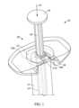
図1は、概して、近位開放端部11aと、遠位端11b(図2A、図2B、図5A、及び図5B)と、空洞13と、フランジ部12と、プランジャロッド16と、ストッパ構成要素18(図5A及び図5B)と、戻り止め20とを有するバレル11を有するシリンジ10などの注入デバイス10の斜視図である。FIG. 1 is a perspective view of an
いくつかの例においては、戻り止めとシリンジとの間の係合によって、滅菌ガスは、各戻り止めとシリンジとの間の閉塞空間又は部分閉塞空間に到達できず、それにより、これらの表面を完全に又は適切に滅菌し損なう場合がある。加えて又は或いは、滅菌ガスは、これらの閉塞空間又は部分閉塞空間から効果的にパージされず、それにより、チャンバにおける指定された滅菌工程以上に薬物を滅菌ガスに曝露させる場合がある。これらの状況のいずれか及び/又は両方は望ましくない場合がある。より具体的な例として、図6A~図6Cは、シリンジバレル及びフランジの様々な図を含み、特に閉塞の影響を受けやすい可能性のあるその表面は、参照番号11c(バレル11の近位セクション)及び参照番号12c(フランジ12の近位セクション)で示される。例えば、フランジ上面12c及びバレル外部表面11cは、当該技術分野で周知の戻り止めとそれぞれ係合していることにより、特に閉塞の影響を受けやすい可能性がある。In some instances, due to the engagement between the detents and the syringe, the sterilizing gas may not be able to reach the closed or partially closed spaces between each detent and the syringe, thereby failing to fully or properly sterilize these surfaces. Additionally or alternatively, the sterilizing gas may not be effectively purged from these closed or partially closed spaces, thereby exposing the drug to the sterilizing gas beyond the designated sterilization step in the chamber. Either and/or both of these situations may be undesirable. As a more specific example, FIGS. 6A-6C include various views of a syringe barrel and flange, the surfaces of which may be particularly susceptible to occlusion being indicated by
シリンジバレル遠位端11bは、針又は患者への流体路を完成させるための他の適切な構成要素を含む及び/又は支持する。例えば、シリンジバレル遠位端は、ルアーロック構成要素17(図2A及び図2B)及び/又はルアーロック構成要素17を覆う保護キャップ19(図5A)を含んでもよい。使用前に、ルアーロック構成要素17が針を受け入れることができるように、保護キャップ19は取り外され得る。シリンジバレル近位端11a(図2Aを参照)は、ストッパ構成要素18を遠位方向15に押して、シリンジ10から薬物を排出するためのプランジャロッド16を受け入れてもよい。例えば、ストッパ構成要素18は、空洞13と流体密関係を形成することができる一方で、空洞13に沿って遠位方向15に移動し、シリンジ10の遠位端から薬物を押し動かすこともできる。プランジャロッド16は、遠位方向15におけるプランジャロッド16の移動距離を制限するために及び/又は使用者がプランジャロッド16を押すことをより簡単にするために、プランジャロッド16の本体部分よりも大きな直径を有するプランジャロッド端部14を含んでもよい。プランジャロッド16は一方向構成要素であってもよく、プランジャロッドはストッパに固定的に接続されないため、プランジャロッド16が近位方向(遠位方向15の逆)に移動する場合、ストッパ18はプランジャロッド16と共に移動しない。The syringe barrel
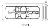
図5A及び図5Bは、ブリスターパック9などのパッケージ9内に配置されたシリンジ10(集合的に、梱包されたシリンジ8)を示す。パッケージ9は、ベース部9aと、ベース部9aにわたって実質的に若しくは完全に延びる及び/又はベース部9aに封止されたTyvekカバー9bなどのカバー9b(図5B)とを含む。Tyvekカバー9bは、Tyvekカバー9bの取り外しをより簡単にするために、一方の側などの少なくとも1つの部分においてベース部9aの枠の外側に延びてもよい。更に又は或いは、ベース部9aは、簡単な取り外しを促すために、Tyvekカバー9bによって密閉されていないタブ部9cを含んでもよい。5A and 5B show a syringe 10 (collectively, packaged syringe 8) disposed within a
シリンジバレル11は、プラスチック、ガラス、又は任意の適切な材料で作製されてもよい。より具体的な例として、シリンジバレル11は、以下の材料、即ち、特定グレードのポリプロピレン(ホモポリマー及び/又はコポリマーポリプロピレン)、シクロオレフィンコポリマー(COC)、シクロオレフィンポリマー(COP)、又は他の適切な材料のうちの少なくとも1つ以上を含むプラスチック材料で作製されてもよい。より具体的な例として、シリンジバレルは、シクロオレフィンポリマー(COP)で作製されてもよい。The
戻り止め20は、シリンジのグリップ、使用性、及び/又は人間工学的な設計を向上させるために、シリンジ10と結合又は接続されてもよい。フランジ12は、シリンジバレル11の直径よりも大きな直径を含んでもよく、使用中に使用者がシリンジ10を操作することを可能にする指置きとしての役割を果たしてもよい。例えば、使用者は、自身の親指を使用してプランジャロッド端部14を押している間、自身の指の2本以上をフランジ12に載せることができる。より具体的な例として、フランジ部を効果的に延ばし、それによってグリップ面の長さを延ばすために、戻り止め20は、フランジ部12と結合されていてもよい。更により具体的な例として、特に、眼科適用などのシリンジの特定用途においては、シリンジのグリップ、使用性、及び/又は人間工学的な設計を向上させるために、使用者はより大きな有効グリップ面を有することが望ましい場合がある。しかしながら、製造及び配送中の空間の制約、標準的なシリンジ/フランジ構成を使用する規模の利点のために、フランジ部12の大きさを増大させることが望ましくない場合がある。更に、シリンジは、拡大したフランジサイズを有するシリンジに適応できない外形を有するオートインジェクタにおいて一般に使用されている。したがって、製造プロセスの時点でシリンジに取り付けることができる及び/又は結合させることができる戻り止め構成要素などの追加の構成要素を有することが望ましい場合がある。The
戻り止めは、任意の適切な材料から製造されてもよい。例えば、戻り止めは、ポリプロピレン(「PP」)又はアクリロニトリルブタジエンスチレン(「ABS」)から成形されてもよい。ABSは、PP及び他の材料よりも硬いという利点を有し得、戻り止めがより軽量になり得る。より具体的な例として、戻り止めがPPで作製されている場合、厚さ1.5mmの最低壁厚を有し得る一方で、戻り止めがABSで作製されている場合、1mmの最低壁厚を有し得る。The detents may be manufactured from any suitable material. For example, the detents may be molded from polypropylene ("PP") or acrylonitrile butadiene styrene ("ABS"). ABS may have the advantage of being harder than PP and other materials, allowing the detents to be lighter. As a more specific example, if the detents are made from PP, they may have a minimum wall thickness of 1.5 mm, while if the detents are made from ABS, they may have a minimum wall thickness of 1 mm.
戻り止め20はまた、シリンジ10に対するストッパ構成要素18の不意の動きを制限する、限定する、低減する、又は阻止するために用いられてもよい。例えば、戻り止め20は、プランジャロッド16の不意の動きを低減する又は阻止するために、フランジ12上に嵌合されてもよい。例えば、図1に示すように、戻り止め20は、ロック面34を有してもよく、ロック面34は、プランジャロッド16に係合し、これら2つの構成要素間の遠位方向15における相対運動を制限する又は阻止する。より具体的な例として、プランジャロッド16は、ロックリング16aを有してもよく、ロックリング16aは、プランジャロッド16の残り部分よりも大きな直径を有するが、空洞よりも小さな直径を有し、戻り止め20のロック面34は、ロックリング16aが戻り止め20を越えて近位方向に移動することができないように、ロックリング16aよりも小さな直径を有し得る。この構成は、プランジャロッド16の近位方向の移動を制限するように機能するであろう。The
上記の理由及びおそらくはその他の理由から、使用者は、一般に、シリンジ10を使用する前に戻り止め20を取り外さない。For the reasons above and possibly others, users typically do not remove the
製造及び/又は組立プロセス時に注入デバイスを外部滅菌することが望ましい場合がある及び/又は規制によって求められる場合がある。更に、プレフィルドシリンジのいくつかの用途(特定の眼科用途など)では外部滅菌が求められる。例えば、21 CFR 200.50は、「眼科用製剤及びディスペンサは無菌とすべきである」と示している。更に、ANSI/AAMI ST67:2011/(R)2017には、「健康ケア製品の滅菌-「無菌」とラベル付けされる製品の無菌性保証水準(SAL:sterility assurance level)を選択するための要件及びガイダンス(“Sterilization of health care products-Requirements and guidance for selecting a sterility assurance level(SAL)for products labeled‘sterile”)」が記載されており、セクション4.1.1は、「一般に、健康ケア製品の最終滅菌には10~6のSAL値が使用されている」と記載している。更に、ST67及びEN556-1:2006の付録Aは、以下のように記載している。「医療デバイスの滅菌-医療デバイスが「無菌」と示されるための要件-パート1:最終滅菌される医療デバイスの要件(“Sterilization of medical devices-Requirements for medical devices to be designated“STERILE”-Part 1:Requirements for terminally sterilized medical devices”)」...セクション4.1:「最終滅菌される医療デバイスが「無菌」と示されるためには、デバイス上/内に生存微生物が存在する理論上の確率は、1x10-6以下とすべきである。」したがって、汚染微生物数が1x10-6(例えば、1x10-6)未満であることが望ましい及び/又は求められる場合がある。 External sterilization of the injection device during the manufacturing and/or assembly process may be desirable and/or required by regulations. Additionally, some applications of prefilled syringes (such as certain ophthalmic applications) require external sterilization. For example, 21 CFR 200.50 indicates that "ophthalmic preparations and dispensers should be sterile." Furthermore, ANSI/AAMI ST67:2011/(R)2017 describes "Sterilization of health care products-Requirements and guidance for selecting a sterility assurance level (SAL) for products labeled 'sterile'" and section 4.1.1 states that "SAL values of 10 to 6 are commonly used for terminal sterilization of health care products." Furthermore, Appendix A of ST67 and EN556-1:2006 states: "Sterilization of medical devices - Requirements for medical devices to be designated "STERILE" - Part 1: Requirements for terminally sterilized medical devices"... Section 4.1: "For a terminally sterilized medical device to be designated "sterile", the theoretical probability of viable microorganisms present on/in the device should be less than or equal to 1x10⁻⁶. "Accordingly, a bioburden of less than 1 x 10⁻⁶ (eg, 1 x10⁻⁶ ) may be desirable and/or required.
したがって、本明細書に開示される実施形態は、これらのタイプの用途において特に有利である。本明細書で使用する場合、「外部滅菌」及び/又は「外部滅菌する」という用語は、注入デバイスが組み立てられた後の注入デバイスの滅菌プロセスを指す。例えば、図に示される注入デバイスは、シリンジ10(空洞13内に薬物を有する)、プランジャロッド16、戻り止め20、及び保護キャップ(図示せず)が全て組み立てられた後に外部滅菌され得る。外部滅菌プロセス時、注入デバイスは、典型的には、滅菌チャンバ内に配置され、所定の時間長及び他の指定条件(温度及び圧力など)においてエチレンオキサイド(EtO)、二酸化窒素(NO2)、蒸発させた過酸化水素(VHP)、二酸化炭素(CO2)、二酸化塩素、又は任意の他の適切なガスなどの滅菌ガスに曝される。その後、滅菌サイクル後、滅菌ガスはチャンバからパージされ、別の所定の時間長及び他の指定条件(温度及び圧力など)において、注入デバイスはチャンバ内に留まる(滅菌ガスを実質的に又は完全に有しない)。Thus, the embodiments disclosed herein are particularly advantageous in these types of applications. As used herein, the terms "external sterilization" and/or "externally sterilizing" refer to a sterilization process of an injection device after it has been assembled. For example, the injection device shown in the figures may be externally sterilized after the syringe 10 (with drug in cavity 13),
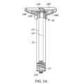
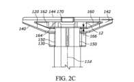
図2A~図2Hは、図2A~図2Cに示すようなシリンジ10と共に用いられ得る別の例示的な戻り止め120を示す。戻り止め120は、概して、シリンジ10の少なくとも一部分の周りに延びるカラー部130と、使用者が取り扱う及び/又は把持するための外部グリップ部140と、空気流が戻り止めとシリンジとの間の空間を通ることを可能にする又は促進するのに役立つ隆起部150などの少なくとも1つの突起と、シリンジフランジ12の少なくとも一部分を受け入れるための空洞160と、プランジャロッド16が戻り止め120を通って延びることを可能にする開口部170とを含んでもよい。2A-2H show another
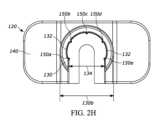
図2D~図2Hに最もよく示されるようなカラー部130は、シリンジ10の少なくとも一部分の周りに延びる内面132を画定する。より具体的な例として、内面132は、シリンジ10のバレル11の周囲の大部分の周りに延びる略環状面である。更により具体的な例として、内面132は、バレル11の遠位部11cの周囲の大部分の周りに延びる。この部分については図13A~図13Cに詳しく記載する。内面132は、バレル11と概ね同じ曲率を有してもよく、内面132の長さにわたってバレル11の周りに延びてもよい。図2Dに示すように、内面132は、戻り止め120がシリンジ10と結合することを可能にする、カラー130及び内面132がカラー130の開口部134にわたって途切れる場所の他は、略円形/環状の状態でカラー130の内面に延びてもよい。より具体的な例として、開口部134により、シリンジ10が戻り止め120にスナップフィット構成で接触するまでシリンジ10を戻り止め120に向けて(又はこの逆に)摺動させることによって、戻り止め120がシリンジ10を受け入れることを可能にする。別の例として、内面132は、バレル11の周囲の周りに約270度にわたって延びる。カラー130の軸方向長さ(バレル11の軸線に沿って測定した)は、約5ミリメートルであるが、その他の適切な長さを有してもよい。カラー130の軸方向長さが増加するにつれて、シリンジ10と戻り止め120との間の接続がよりしっかりとしたものになり得る。また又は或いは、カラー130の軸方向長さが増加するにつれて、重心は軸方向長さの中点から更に遠くに離れ得る。それにより、製造中に戻り止め120を方向付けることがより容易になる。より具体的な例として、シリンジを自動で組み立てること、及びシェーキングトレイ内の複数の戻り止め構成要素を同様に方向付けて製造プロセスを簡素化するために、パン若しくはボウルなどの「シェーカ」又は「フィーダ」受け口を用いることが望ましい場合がある。フィーダボウルは、例えば、受け口の側壁に沿って螺旋路軌道を備える中央受け口を有してもよく、螺旋路軌道は、側壁を通って受け口の上縁(ここで部品は組立ステーションに供給され得る)に向けて上方に部品を運ぶ。多くの場合、フィーダボウルは、構成要素の重心が構成要素の軸方向長さの中点から少なくともある程度の距離離れており、それにより、全て又は実質的に全ての構成要素が構成要素の「重い方」に向けてひっくり返る場合により信頼性が高くなる及び/又は効果的である。戻り止め120の重心は、図2Fに参照番号136によって示される。更に、フィーダは、多くの場合、部品が(少なくとも1つ又は2つの軸線に沿って)何らかの非対称特徴を有する場合により信頼性が高くなり、フィーダは、不適切に方向付けられた部品をボウルに戻すように押しやることができる軌道縁部又はパターンを有する。この場合、軌道縁部又はパターン特徴は、ゲートとしての役割を果たす。即ち、部品が正しい向きにある場合、部品はこの特徴と相互作用しないが、部品が誤った向きにある場合、部品はこの特徴と相互作用し、落下してボウル内に戻される。The
上述のように、戻り止め120は、シリンジ10のフランジ12よりも大きな把持面を使用者に提供する。より具体的な例として、図2A及び図2Bに示されるフランジ部12は、最大幅12aが約13ミリメートル及びバレル11直径が約9.5ミリメートルの略楕円形又は長円形の構成を有する。したがって、フランジ部12は、フランジ部12の各側に約2ミリメートルの有効グリップ面を有する。これに比べると、戻り止め120は、最大幅120aが約34ミリメートル、カラー幅130b(図2D及び図2H)が約12ミリメートルである。したがって、戻り止め120の外部グリップ部140は、カラー130の各側に約11ミリメートルの有効グリップ面を有する。As discussed above, the
外部グリップ部140は、戻り止め120の頂面144に対してマイナス約25度の角度142(図2C)を有する。したがって、外部グリップ部140は、シリンジ軸線11dに対して115度の角度を有する。シリンジ軸線11dに対する外部グリップ部140の角度は、使用者が外部グリップ部140に対する十分なグリップを有することを可能にするために、180度よりも90度により近い(即ち、135度以下)ことが望ましい場合がある。外部グリップ部140がシリンジ軸線11dに対して、125度以下、又は120度以下、又は115度以下などのより小さい角度を有することがより望ましい場合がある。外部グリップ部140はまた、リブ若しくは相対的に高い摩擦係数を有する材料などの滑り止め又はグリップ強化特徴を含んでもよい。The external
上述のように、戻り止め120はまた、カラー内面132がシリンジ10から離れるようにシリンジ10に係合する少なくとも1つの隆起部150などの少なくとも1つの突起を含んでもよい。より具体的な例として、戻り止め内面132は、少なくとも1つの突起150を含んでもよく、少なくとも1つの突起150は、内面132から遠ざかる方に延び、フランジ12及び/又はバレル11に係合し、空気流が内面132とシリンジ10との間の空間152を通ることを可能にする又は促進するように構成されている。図2A~図2Hにおいて、戻り止めは、5つの隆起部150a、150b、150c、150d、及び150eを含み、5つの隆起部150a、150b、150c、150d、及び150eは、カラー内面132の周りで全般的に互いに離れており、より好ましくは、戻り止め120とシリンジ10との間に5点係合を形成するように、全般的に互いに等しく離れている。しかしながら、1つ、又は2つ、又は3つ、又は4つ、又は5つ、又は6つ、又は7つ、又は8つ、又は9つ、又は10個以上などの任意の適切な隆起部が使用されてもよい。隆起部150は、戻り止め120のカラー内面132に一体形成されてもよい、又は隆起部150は、カラー内面132に取り付けられた別個の構成要素であってもよい。いずれの場合においても、隆起部150は、内面132とシリンジ10との間に空間152を設けつつも、協働して、戻り止め120とシリンジ10との間の比較的しっかりとした嵌合を可能にし得る。例えば、隆起部150は、スナップフィット関係でバレル11に係合してもよい。図に示される隆起部150a、150b、150c、150d、及び150eはシリンジ軸線11dと略平行であるが、これらは別の構成を有してもよい。図に示される隆起部150a、150b、150c、150d、及び150eは、図2Eに示すようにカラー130の全高138に沿って延びてもよい、又は隆起部150a、150b、150c、150d、及び150eは、カラー130の高さの一部分のみに沿って延びてもよい。As discussed above, the
空気流が内面132とシリンジ10との間の空間152(図2D)を通ることを可能にすることにより、戻り止め120とシリンジ10は、協働して、カラー内面132とバレル又はフランジとの間の任意の閉塞領域を最小限にする又は排除する。例えば、一実施形態において、隆起部150は、カラー内面132がバレル11に係合する部分のみにある。By allowing air flow through the space 152 (FIG. 2D) between the
その代わりに、図2A~図2Hに示される戻り止め120の突起は、空気流が内面132とシリンジ10との間の空間152を通過することを可能にする任意の適切な構成を有してもよい。例えば、一実施形態において、突起は、略円形の塊、こぶ、又はその他の非線形の突起と入れ替えてもよい。より具体的な例として、戻り止め120の突起は、空洞内の代わりにカラー130上に配置されてもよい。Alternatively, the protrusions of the
上述のように、戻り止め120は、シリンジフランジ12の少なくとも一部分を受け入れるための空洞160を含む。より具体的な例として、空洞は、対向表面162、164(図2E及び図2F)によって画定される。図2Cに示すように、対向表面162と対向表面164との間の距離は、対向表面162、164のうちの少なくとも1つとフランジ12の上面及び下面との間に隙間166が存在するように、フランジ12の軸方向高さより大きくてもよい。より具体的な例として、図2Cに示される隙間166は、下対向表面162とフランジ12の下面との間にあるが、他の構成では、同様の隙間は、上対向表面164とフランジの頂面との間に存在してもよい又はフランジ12の両側(上部及び下部)に存在してもよい。隙間166及び本明細書に記載される他の類似の隙間は、空気流を通す若しくは促すために及び/又は閉塞空間を阻止する若しくは低減するために有利な場合がある。As mentioned above, the
空洞160は、好ましくは、カラー130とバレル11との間の確実な係合を促すためにフランジ12全体を受け入れるような形状及び大きさにされている。また、空洞160は、製造を簡略化する及び/又は改善するために、フランジ12を任意の向きで受け入れるような形状及び大きさにされてもよい。例えば、空洞160は、任意の向きにおけるその最大幅を有するフランジ12を受け入れるような形状及び大きさにされてもよい。より具体的な例として、空洞160の最小幅は、フランジを任意の向きで挿入することができるように及び/又はフランジ12が戻り止め120内で自由に回転することができるように、フランジ12の最大幅よりも少なくともわずかに大きくてもよい。The
上述したように、開口部170は、プランジャロッド16が戻り止め120を通って延びることを可能にする。開口部170は、ロックリング16aが開口部170を画定する表面に当接する又は係合するとき以外はプランジャロッド16の自由な動きを可能にするような大きさにされ得る。より具体的な例として、開口部170は、図1の参照番号16で示されるプランジャロッドの部分(即ち、プラスの形状の断面を有するプランジャロッドのセクション)の直径又は幅よりも少なくともわずかに大きな直径又は幅を有してもよいが、開口部170の直径又は幅は、ロックリング16aの直径又は幅よりも少なくともわずかに小さく、それによって、プランジャロッド16が図1に示される地点を越えて近位方向に移動することを阻止する又は制限する。As discussed above, the
図7を参照して、本開示の一実施形態による薬物送達デバイスを組み立て、外部滅菌する例示的な方法を記載する。第1の工程時(ボックス2)、薬物送達デバイスの少なくともいくつかの個々の構成要素は、多くの場合、製造施設によって受け入れられる前に滅菌される。例えば、シリンジバレル及びプランジャストッパ及び薬物製品と直接接触し得る任意の他の構成要素は、この工程時に滅菌され得る。この工程では、図1~6Cに示される構成要素が挙げられるがこれらに限定されない、薬物送達デバイスの組み立てられていない様々な構成要素を滅菌するために、既知の様々な手法を用いることができる。第2の工程時(ボックス3)、バレルは充填され、ストッパ(「プランジャストッパ」としても知られる)はバレルと組み立てられる。組立工程はまた、以下、即ち、プランジャロッド、フランジエクステンダ、ルアーロックを備えた先端キャップ、針、剛性針シールド、及び/又は図1~図6Cに示されるものなどの戻り止めのうちの少なくともいくつかを追加することを含んでもよい。これら構成要素の少なくともいくつかは、互いに予め組み立てられてもよいが、これらはまた、例えば充填プロセスが無菌的に実施される場合には充填ラインにて組み立てられてもよい。また、シリンジは、通常、両方の構成要素を有するのではなく、先端キャップルアーロック先端又は取付式の(例えば、固定式の)針のいずれかを有する。次いで、外部滅菌工程(点線ボックス1により示される)に進む。7, an exemplary method of assembling and externally sterilizing a drug delivery device according to one embodiment of the present disclosure is described. During the first step (Box 2), at least some of the individual components of the drug delivery device are often sterilized before being received by a manufacturing facility. For example, the syringe barrel and plunger stopper and any other components that may be in direct contact with the drug product may be sterilized during this step. This step may use various known techniques to sterilize the various unassembled components of the drug delivery device, including but not limited to the components shown in FIGS. 1-6C. During the second step (Box 3), the barrel is filled and the stopper (also known as the "plunger stopper") is assembled with the barrel. The assembly step may also include adding at least some of the following: a plunger rod, a flange extender, a tip cap with a luer lock, a needle, a rigid needle shield, and/or a detent such as those shown in FIGS. 1-6C. At least some of these components may be pre-assembled with each other, but they may also be assembled at the filling line, for example if the filling process is performed aseptically. Also, syringes typically have either a tip cap luer lock tip or an attached (e.g., fixed) needle, rather than having both components. They then proceed to an external sterilization step (indicated by dotted box 1).
ボックス4において、シリンジは前準備される。二酸化窒素(NO2)を用いるプロセスでは、前準備には、以下の工程、即ち、保管庫からサンプルを取り出すこと、シリンジを所望の時間量(例えば、30分、90分、2時間、又は任意の望ましい時間量)にわたって室温条件での平衡状態に調整すること、及びシリンジを滅菌チャンバに配置することの少なくともいくつか又は全てを含んでもよい。前準備は、チャンバの内部又は外部で行われ得る。In box 4, the syringe is primed. For processes using nitrogen dioxide (NO2), priming may include at least some or all of the following steps: removing the sample from storage, allowing the syringe to equilibrate at room conditions for a desired amount of time (e.g., 30 minutes, 90 minutes, 2 hours, or any desired amount of time), and placing the syringe in a sterilization chamber. Priming may occur inside or outside the chamber.
エチレンオキサイド(EtO)を用いる場合、前準備工程は、NO2に関して説明した工程とわずかに異なり得る。例えば、シリンジは、滅菌チャンバの内部で(ガス注入なしで)360分間(又は別の望ましい長さの時間)前準備され得る。しかしながら、NO2を用いたプロセスと同様に、EtOを用いた前準備工程は、チャンバの内部又は外部で行われてもよい。When using ethylene oxide (EtO), the priming process may differ slightly from that described for NO2. For example, the syringe may be priming inside the sterilization chamber (without gas injection) for 360 minutes (or another desired length of time). However, as with the NO2 process, the priming process with EtO may be performed inside or outside the chamber.
次いで、ボックス5において、滅菌チャンバは閉じられ、チャンバから全て又は実質的に全ての空気が排出される。次いで、ボックス6において、滅菌チャンバは、75又は80(又は任意の所望の相対湿度の割合の量)などの所望の設定まで加湿される。Then, in
次いで、ボックス7において、所望の滅菌ガスが注入され、所望の滞在時間にわたってチャンバ内に保持される。NO2を用いるレシピでは、ガス注入工程7は、以下の工程、即ち、所望の量のガス(用量濃度)を注入しながら所望の時間量(即ち、滞在時間)にわたってチャンバ内に真空を引くことによってある用量のNO2を送達する、ガスをパージし、真空を解放する、その後、これらの工程を所望のパルス数にわたって繰り返す、のうちのいくつか又は全てを含み得る。所望のパルス数が完了すると、その後最終的に、ガスは(ボックス8にて)パージされ、ガスは滅菌チャンバから除去される。最後に、ボックス9において、チャンバは、全て又は実質的に全ての滅菌ガスがシリンジ及びパッケージからフラッシュされるようにするために、所望のサイクル数にわたって通気される(「通気交換」としても知られる)。いくつかの例では、真空レベルはこれらの工程の間に変化し得る。例えば、滞在時間時の真空は、約590Torrなどの最小限であり得る。Then, in box 7, the desired sterilizing gas is injected and held in the chamber for the desired dwell time. In recipes using NO2, gas injection step 7 may include some or all of the following steps: deliver a dose of NO2 by pulling a vacuum in the chamber for the desired amount of time (i.e., dwell time) while injecting the desired amount of gas (dose concentration), purge the gas, release the vacuum, and then repeat these steps for the desired number of pulses. Once the desired number of pulses is completed, the gas is then finally purged (in box 8) and the gas is removed from the sterilization chamber. Finally, in
この方法は、以下などの工程7~9に関する任意の適切なパラメータを含み得る。
- 真空レベルは、約100~500Torr、約150~400Torr、約150~300Torr、又は別の適切な真空レベルであり得る。
- NO2の用量の濃度は、約2~20ミリグラム毎リットル、約2~10ミリグラム毎リットル、約2~7ミリグラム毎リットル、又は別の適切な用量の濃度であり得る。
- チャンバは、約70~90パーセントの相対湿度又は別の適切な湿度を有し得る。
- 滞在時間は、約2~20分、約2~12分、約2~7分、又は別の適切な滞在時間であり得る。
- パルス数は、約1~24、約1~12、約1~8、約1~4、約1~2、又は別の適切なパルス数であり得る。
- 滅菌チャンバに通気する工程は、約12~35回のサイクル数又は別の適切なサイクル数滅菌チャンバに通気することを含み得る。 The method may include any suitable parameters for steps 7-9, such as:
The vacuum level may be about 100-500 Torr, about 150-400 Torr, about 150-300 Torr, or another suitable vacuum level.
The NO2 dose concentration can be about 2-20 milligrams per liter, about 2-10 milligrams per liter, about 2-7 milligrams per liter, or another suitable dose concentration.
The chamber may have a relative humidity of about 70-90 percent or another suitable humidity.
The residence time may be about 2-20 minutes, about 2-12 minutes, about 2-7 minutes, or another suitable residence time.
The number of pulses can be about 1-24, about 1-12, about 1-8, about 1-4, about 1-2, or another suitable number of pulses.
The step of venting the sterilization chamber may include venting the sterilization chamber for about 12-35 cycles or another suitable number of cycles.
より具体的な例として、表1は、二酸化窒素(NO2)を用いた薬物送達デバイスを滅菌するための異なる例示的な10個のレシピの異なる変数を示す。As a more specific example, Table 1 shows the different variables for ten different exemplary recipes for sterilizing drug delivery devices using nitrogen dioxide (NO2).

別の例として、表2は、NO2を用いた薬物送達デバイスを滅菌するための異なる例示的な6つのレシピの異なる変数を示す。As another example, Table 2 shows different variables for six different exemplary recipes for sterilizing a drug delivery device using NO2.

表1及び表2において、「真空レベル(Torr)」列のラベルは、図1の工程4の間に外部滅菌チャンバに印加される真空力を指す。示されるように、真空力は、20Torrから500Torrまで変化するが、異なる真空力が適切な場合がある。記載の真空力数はその強度の逆であり、20Torrの力は100Torrの力に比べて強く、100Torrの力は500Torrの力に比べて強い(大気圧は、典型的には約760Torr)。真空力が強くなるほど、目的の汚染微生物数の死滅を示す可能性が高くなる。しかしながら、真空力が高くなりすぎた場合、プロセスは、プランジャを望ましくなく移動させる(即ち、無菌バリアを越えて移動させ、無菌性を破る原因となる)などの、薬剤に対して望ましくない効果をもたらす可能性がある。「NO2用量(mg/L)」列は、図7の工程7の間に外部滅菌チャンバに導入される空気のリットル毎のNO2濃度(mg)を指す。示されるように、表1と表2の用量は、5~20mg/Lで変化するが、異なる用量が適切な場合がある。この工程時のNO2の用量が高いほど、薬物送達デバイスがより迅速且つより完全に滅菌される。しかしながら、滅菌ガスの用量が高くなりすぎた場合、プロセスは、薬物バレルの内部を滅菌ガスで汚染する(即ち、滅菌ガスの侵入及び/又はシリンジ構成要素の変色)などの、薬剤に対して望ましくない効果をもたらす可能性がある。「相対湿度(%RH)」列は、図7の工程7の最中の外部滅菌チャンバ内の相対湿度を指す。示されるように、表1及び表2の各列の相対湿度は、75%~80%で変化するが、異なる相対湿度値が適切な場合がある。相対湿度を増加させると、目的の汚染微生物数の死滅を示す可能性も高まる。「滞在時間(分:秒)」列は、滅菌ガスが存在中に薬物送達デバイスが滅菌チャンバにある時間量を指す。表1及び表2に関して、「総滞在時間」は、「滞在時間」列に「パルス数」列を掛けたものに等しい。例えば、表1の第1の行に関して、サンプルは、総滞在時間が80分になる。示されるように、表1及び表2に記載の滞在時間は5~20分で変化するが、異なる滞在時間が適切な場合がある。滞在時間はまた、目的の汚染微生物数の死滅を示す可能性を高める。しかしながら、滞在時間が高くなりすぎた場合、プロセスは、薬物バレルの内部を滅菌ガスで汚染するなどの、薬剤に対して望ましくない効果をもたらす可能性がある。「パルス数」列は、NO2プロセス中に真空を引くことによってガスが注入される回数を指す。示されるように、表1及び表2の各行のパルスは、1~24回で変化するが、異なる値が適切な場合がある。パルス数が高くなるほど、目的の汚染微生物数の死滅を示す可能性が高くなる。しかしながら、パルス数が高くなりすぎた場合、プロセスは、薬物バレルの内部を滅菌ガスで汚染するなどの、薬剤に対して望ましくない効果をもたらす可能性がある。「通気数」を参照する列は、チャンバからガスがパージされた(図7のボックス8)後にチャンバが通気される(図7のボックス9)回数を指す。例示的なプロセスは、12、24、28、70回、又は任意の望ましい数の通気交換を用い得る。ある時点までは、通気数を増加させることにより、製造業者は、全て又は実質的に全ての滅菌ガスがシリンジ及びパッケージから除去される可能性を高めることができる(ポストパージ)。In Tables 1 and 2, the labels in the "Vacuum Level (Torr)" column refer to the vacuum force applied to the external sterilization chamber during step 4 of FIG. 1. As shown, the vacuum force varies from 20 Torr to 500 Torr, although different vacuum forces may be appropriate. The listed vacuum force numbers are inverse to their strength, with 20 Torr being stronger than 100 Torr, which is stronger than 500 Torr (atmospheric pressure is typically about 760 Torr). The stronger the vacuum force, the more likely it is to demonstrate kill of the desired bioburden. However, if the vacuum force becomes too high, the process may have undesirable effects on the drug, such as undesirably displacing the plunger (i.e., displacing it across the sterile barrier, causing a breach of sterility). The "NO2 Dose (mg/L)" column refers to the NO2 concentration (mg) per liter of air introduced into the external sterilization chamber during step 7 of FIG. 7. As shown, the doses in Tables 1 and 2 vary from 5-20 mg/L, although different doses may be appropriate. The higher the dose of NO2 during this step, the more quickly and more completely the drug delivery device will be sterilized. However, if the dose of sterilizing gas becomes too high, the process may have undesirable effects on the drug, such as contaminating the interior of the drug barrel with sterilizing gas (i.e., sterilizing gas ingress and/or discoloration of syringe components). The "Relative Humidity (% RH)" column refers to the relative humidity in the external sterilization chamber during step 7 of FIG. 7. As shown, the relative humidity in each column of Tables 1 and 2 varies from 75% to 80%, although different relative humidity values may be appropriate. Increasing the relative humidity also increases the likelihood of demonstrating kill of the desired bioburden. The "Dwell Time (min:sec)" column refers to the amount of time the drug delivery device is in the sterilization chamber while sterilizing gas is present. For Tables 1 and 2, the "Total Dwell Time" is equal to the "Dwell Time" column multiplied by the "Number of Pulses" column. For example, for the first row in Table 1, the sample will have a total residence time of 80 minutes. As shown, the residence times listed in Tables 1 and 2 vary from 5 to 20 minutes, but different residence times may be appropriate. The residence time also increases the likelihood of indicating kill of the desired bioburden. However, if the residence time becomes too high, the process may have undesirable effects on the drug, such as contaminating the inside of the drug barrel with sterilizing gas. The "Number of Pulses" column refers to the number of times that gas is injected by pulling a vacuum during the NO2 process. As shown, the pulses in each row in Tables 1 and 2 vary from 1 to 24, but different values may be appropriate. The higher the number of pulses, the more likely it is that it will indicate kill of the desired bioburden. However, if the number of pulses becomes too high, the process may have undesirable effects on the drug, such as contaminating the inside of the drug barrel with sterilizing gas. The column referring to "Number of Vents" refers to the number of times that the chamber is vented (
表1及び表2の各レシピ(NO2)に関して、図1のボックス1内に入れられた各工程は、室温(摂氏25度)で実施され得るが、その他の適切な温度が使用される可能性がある。しかしながら、摂氏約2度~摂氏約8度などの他の温度、又は薬剤に望ましくない影響を及ぼさない任意の他の望ましい温度が使用される可能性がある。For each recipe (NO2) in Tables 1 and 2, each step enclosed within
表3は、NO2を用いた薬物送達デバイスを滅菌するための異なる例示的な10個のレシピの異なる変数を示す。Table 3 shows the different variables for ten different exemplary recipes for sterilizing drug delivery devices using NO2.

エチレンオキサイド(EtO)を用いる場合、ガス注入工程(ボックス7)はわずかに異なる。例えば、ガス注入工程7は、以下の工程、即ち、所望の量(用量濃度)のガスを注入しながら所望の時間量(即ち、滞在時間)にわたってチャンバ内に真空を引くことによってある用量のEtOを送達する、その後、ガスをパージする、のうちのいくつか又は全てを含んでもよい。換言すると、EtOを用いる場合、NO2に関して上述した好ましい複数回のパルスよりもむしろ1回のみのパルスを実行することが望ましい場合がある。工程8(ガスパージ)及び工程9(通気)については、EtOを用いた例示的なプロセスは、NO2に関して上述したように進められる。When using ethylene oxide (EtO), the gas injection step (box 7) is slightly different. For example, gas injection step 7 may include some or all of the following steps: deliver a dose of EtO by pulling a vacuum in the chamber for a desired amount of time (i.e., residence time) while injecting a desired amount (dose concentration) of gas, and then purging the gas. In other words, when using EtO, it may be desirable to perform only one pulse rather than the preferred multiple pulses described above for NO2. For steps 8 (gas purge) and 9 (venting), the exemplary process using EtO proceeds as described above for NO2.
図に示される戻り止めの少なくともいくつかに致死試験を行った。例えば、滅菌サイクル前に、プレフィルドシリンジに、1x10^6~6x10^6CFU(例えば、1,000,000~6,000,000CFU)のゲオバチルスステアロサーモフィルス(Geobacillus stearothermophilus)を「添加した」。より具体的な例として、プレフィルドシリンジの戻り止め部及びバレル部に、1~6x10^6CFUのゲオバチルスステアロサーモフィルス(Geobacillus stearothermophilus)を添加した。本明細書で使用する場合、「CFU」という用語は、「コロニー形成単位」を指す。「コロニー形成単位」は、サンプル中の生存細菌又は真菌細胞の数を推定するために使用される単位である(「生存」とは、制御された条件下で二分裂により増殖する能力である)。ゲオバチルスステアロサーモフィルス(Geobacillus stearothermophilus)(以前はバシラスステアロサーモフィラス(Bacillus stearothermophilus))は、桿状のグラム陽性菌であり、ファーミクテス(Firmicutes)門の一員である。この細菌は好熱性であり、土壌、温泉、海洋堆積物中に広く分布しており、食品の腐敗の原因となる可能性がある。したがって、添加済みのプレフィルドシリンジを様々な滅菌パラメータを使用して滅菌し、滅菌プロセスの致死性を測定し、無菌性保証水準(SAL)を評価した。以下により詳細に記載するように、プレフィルドシリンジにバイオロジカルインジケータを添加した又は直接接種した。At least some of the detents shown in the figures were subjected to lethality testing. For example, the pre-filled syringe was "spiked" with 1x10^6-
特に、本明細書に開示される戻り止め部20などの異なる戻り止め部の致死試験を行った。表4は、戻り止め部20を有する様々なプレフィルドシリンジに対するNO2に基づく滅菌の効果を評価する致死試験の結果を示す。In particular, lethality testing of different detents, such as the

各レシピ番号に関して、5つのサンプル(又は1つ以上のサンプルに対して少なくとも5つの試験位置)に試験を行った。表4は、「添加した戻り止め」及び「添加したバレル」列において、各レシピに関して、5つのサンプルのうちのいくつが目標の致死性に達したかを示す。例えば、この試験の目標の致死性は、10^6の無菌性保証水準(SAL)であった。換言すると、この試験の目標の致死性は、(滅菌前対滅菌後)に存在する細菌数の6対数減少であった。より具体的な例として、レシピ番号1に関しては、戻り止め領域(「添加した戻り止め」列のレシピ番号1に対応する行)について、試験を行った5つのサンプルのうちの1つがこの目標の致死性に達したが、バレル領域(「添加したバレル」列のレシピ番号1に対応する行)については、試験を行ったサンプルの5つ全部がこの目標の致死性に達した。レシピ番号1~4(図2A~図2Hに示される戻り止め20を用いた)の添加した戻り止めの試験結果は、直接接種により試験されたものである一方で、レシピ番号5~14(別の戻り止め120を用いた)の添加した戻り止め試験結果は、バイオロジカルインジケータにより試験されものであることに留意されたい。また、「-」記号は、これらのパラメータ/サンプルについてデータが報告されていないことを示すことに留意されたい。試験方法の違いは別にして、突起を有する戻り止めを用いて試験を行ったサンプルは、突起のない戻り止めを用いたサンプルに比べると、より高い比率で目標の致死性を達成した。上述のように、隆起部は、閉塞空間を最小限にし及び/又は阻止し、その代わりに、プレフィルドシリンジの様々な構成要素、特に、戻り止め領域及びフランジ領域に殺菌薬が完全に又は実質的に到達することを可能にする。For each recipe number, five samples (or at least five test positions for one or more samples) were tested. Table 4 shows how many of the five samples reached the target lethality for each recipe in the "Detents Added" and "Barrel Added" columns. For example, the target lethality for this test was a Sterility Assurance Level (SAL) of 10^6. In other words, the target lethality for this test was a 6 log reduction in the number of bacteria present (pre-sterilization vs. post-sterilization). As a more specific example, for
異なる滅菌パラメータについて、侵入研究に関する試験も行った。上述のように、外部滅菌中に目標の致死性を達成することが望ましいが、薬物製品チャンバへの滅菌ガスの侵入を低減する、最小限にする及び/又は実質的に阻止することも望ましい。しかしながら、2つの目標(致死性を達成することと侵入を最小限にすること)は、相反する又は相殺する関心事であり得る。例えば、より高い致死率を達成する可能性を向上させることのできあるいくつかの滅菌パラメータは、滅菌ガスの侵入が高くなる可能性を上昇させる場合がある。以下の表5及び図8は、薬物製品チャンバに対するNO2に基づく滅菌の異なるレシピの効果を評価する侵入研究の結果を示す。Different sterilization parameters were also tested for intrusion studies. As discussed above, it is desirable to achieve a target lethality during external sterilization, but it is also desirable to reduce, minimize, and/or substantially prevent intrusion of sterilization gas into the drug product chamber. However, the two goals (achieving lethality and minimizing intrusion) may be conflicting or offsetting concerns. For example, some sterilization parameters that may improve the likelihood of achieving a higher lethality rate may increase the likelihood of a higher intrusion of sterilization gas. Table 5 below and Figure 8 show the results of an intrusion study evaluating the effect of different recipes of NO2-based sterilization on the drug product chamber.

右側の最後の4列(「製品中のNO2含有量(PPM)」とまとめてラベル付けされている)は、薬物製品容器に侵入したNO2の含有量、より具体的には、薬物容器に侵入したNO2の含有量、より具体的には、液体中の百万分率の硝酸塩として測定されたNO2レベルを指す。このグループ内の、「1日目」、「14日目」、及び「30日目」とラベル付けされた最初の3列は、滅菌プロセス後、異なる時に測定した侵入率を指す。このグループ内の、「対照」とラベル付けされた最後の列は、NO2とサンプルの生成物(注射用水)である硝酸塩(NO3)の基準レベルを指す。1日目などの「曝露させた」サンプルと比較すると、対照の「曝露させていない」サンプルは、曝露させたサンプルと対照との間の基本的な差異を提供する。例えば、試験番号5については、1日目の侵入率は0.342であり、対照は0.336であるため、曝露させたサンプルと曝露させていないサンプルとの間の差は、0.006PPMであり得る。別の関連する可能性のあるパラメータとして、試験方法は、+/-0.1PPMの誤り率を有し得る。The last four columns on the right (collectively labeled "NO2 Content in Product (PPM)") refer to the content of NO2 that entered the drug product container, more specifically the NO2 levels measured as parts per million nitrate in the liquid. The first three columns in this group, labeled "
一般に、侵入を最小限にすること又は実質的に若しくは完全に阻止することが望ましい場合があるが、3PPM、1PPMの、又は別の適切な限界の侵入量を超えることを避けることが望ましい場合がある。上記の表5の列に記載されたものなどの「未加工の」30日目の値を用いることが望ましい場合がある、又は対照値に基づいて調整された「補正済みの」30日目の値を用いることが望ましい場合がある。上記表5及び図8に示されるように、ほぼ全ての侵入値は、1PPMの閾値未満である(唯一の例外は、サンプル11の30日目の測定値である)。また、上記表5及び図8に示されるように、異なる真空力、パルス数、及び通気数の変化は、侵入測定値に異なる効果を及ぼす。これらのパラメータ及び傾向を利用して、所望の侵入レベル未満を維持しながら目標の致死性を達成する滅菌パラメータを決定することができ得る。In general, it may be desirable to minimize or substantially or completely prevent intrusion, but to avoid exceeding intrusion levels of 3 PPM, 1 PPM, or another appropriate limit. It may be desirable to use "raw" 30-day values, such as those listed in the columns of Table 5 above, or "corrected" 30-day values adjusted based on the control values. As shown in Table 5 above and FIG. 8, nearly all intrusion values are below the 1 PPM threshold (the only exception is the 30-day measurement for sample 11). Also, as shown in Table 5 above and FIG. 8, different vacuum powers, pulse numbers, and airflow rate changes have different effects on intrusion measurements. These parameters and trends may be utilized to determine sterilization parameters that achieve the target lethality while maintaining below the desired intrusion levels.
二酸化窒素(NO2)は、滅菌ガスとして多くの利点を提供するが、いくつかの例では、滅菌プロセスにより注入デバイス及び/又はその構成要素の表面に変色が生じる場合がある。例えば、以下の構成要素、即ち、シリンジ、シリンジバレル、戻り止めデバイス、ストッパ、プランジャロッド、及び/又は保護キャップの1つ以上が変色する可能性がある。別の例として、ブリスターパックのピールオフカバーなどの注入デバイスのパッケージも変色する可能性がある。変色は、一般に、審美的理由及びその他の理由から望ましくない。While nitrogen dioxide (NO2) offers many advantages as a sterilizing gas, in some instances the sterilization process may cause discoloration of the surfaces of the injection device and/or its components. For example, one or more of the following components may become discolored: the syringe, the syringe barrel, the detent device, the stopper, the plunger rod, and/or the protective cap. As another example, the packaging of the injection device, such as the peel-off cover of a blister pack, may also become discolored. Discoloration is generally undesirable for aesthetic and other reasons.
材料の種類が、外部滅菌工程による変色の低減、軽減、及び/又は防止に関連し得る。例えば、いくつかのプラスチック材料は、変色を他のプラスチック材料に比べてより効果的に阻止する及び/又は隠すことができる。より具体的な例として、ポリプロピレンは、ポリカーボネートなどの他の材料と比較すると変色の低減(例えば、黄変の低減)を提供し得る。更により具体的には、特定のポリプロピレンブレンドは、その他に比べて変色を阻止すること及び/又は隠すことにおいて更により効果的であり得る。別の例として、ポリエチレンは、他の材料に比べて変色をより効果的に阻止し得る及び/又は隠し得る別の材料である。更に別の例として、ポリエチレンテレフタレート(PET)及びポリエチレンテレフタレートグリコール(PETG)などのポリエステルは、他の材料に比べて変色をより効果的に阻止し得る及び/又は隠し得る。別の例として、ポリスチレン(PS)又はアクリロニトリルスチレンアクリレート(ASA)などのポリスチレンも、他の材料に比べて変色をより効果的に阻止し得る及び/又は隠し得る。ポリスチレンは、NO2との相互作用中に起こるものを含む酸化反応に耐性があり得る。アクリロニトリルブタジエンスチレン(ABS)は、注入デバイス及び/又はパッケージの特定の構成要素に好適であり得る。なぜなら、ABSは、透明色ではなく白色のスチレン系樹脂であり、それによって変色を阻止する及び/又は隠す可能性があるからである。ブリスターパックは、ポリエチレンテレフタレートグリコール(PETG)などの任意の適切な材料から作製されてもよい。The type of material may be relevant to the reduction, mitigation, and/or prevention of discoloration due to the external sterilization process. For example, some plastic materials may more effectively inhibit and/or hide discoloration than other plastic materials. As a more specific example, polypropylene may provide reduced discoloration (e.g., reduced yellowing) compared to other materials such as polycarbonate. Even more specifically, certain polypropylene blends may be even more effective at inhibiting and/or hiding discoloration than others. As another example, polyethylene is another material that may more effectively inhibit and/or hide discoloration than other materials. As yet another example, polyesters such as polyethylene terephthalate (PET) and polyethylene terephthalate glycol (PETG) may more effectively inhibit and/or hide discoloration than other materials. As another example, polystyrenes such as polystyrene (PS) or acrylonitrile styrene acrylate (ASA) may also more effectively inhibit and/or hide discoloration than other materials. Polystyrene may be resistant to oxidation reactions, including those that occur during interaction with NO2. Acrylonitrile butadiene styrene (ABS) may be preferred for certain components of the injection device and/or packaging because it is a white, rather than clear, styrene-based resin, which may inhibit and/or hide discoloration. Blister packs may be made from any suitable material, such as polyethylene terephthalate glycol (PETG).
材料の色も、外部滅菌工程による変色の低減、軽減、及び/又は防止に関連し得る。例えば、ABSに関して上述したように、いくつかの材料は、それらを、変色を低減する、軽減する及び/又は防止するのにより適したものにする特定の色、色素、又は色調を天然に有し得る。追加的に又は代替的に、注入デバイス構成要素及び/又はパッケージを形成するために使用される材料に色合いを追加することで、変色及び/又はその影響を阻止することができる。より具体的な例として、青色又は灰色の色調がこの目的に特に好適であり得る。青色又は灰色の色調は、例えば、二酸化チタン(一般に白色色素を得るため)及び/又はカーボンブラック(一般に黒色色素を得るため)の混合物から添加され得る。The color of the material may also be relevant to reducing, mitigating, and/or preventing discoloration due to the external sterilization process. For example, as discussed above with respect to ABS, some materials may naturally have a particular color, pigment, or shade that makes them better suited to reducing, mitigating, and/or preventing discoloration. Additionally or alternatively, a tint may be added to the materials used to form the infusion device components and/or packaging to counter discoloration and/or its effects. As a more specific example, a blue or gray shade may be particularly suitable for this purpose. A blue or gray shade may be added, for example, from a mixture of titanium dioxide (generally to obtain a white pigment) and/or carbon black (generally to obtain a black pigment).
添加剤及び/又は安定剤も、外部滅菌工程による変色を低減する、軽減する及び/又は防止するために用いてよい。例えば、酸化防止剤が挙げられるがこれに限定されない樹脂添加剤及び安定剤のレベルを増加すると、変色の出現を低減するのに有益な場合がある。上述のように、NO2滅菌による変色の少なくともいくらかは酸化プロセスに関連し得るため、酸化の効果を最小限にする又は低減することで変色を低減させることができる。このような添加剤は、現在、標準的な樹脂に添加されているが、添加剤の量を増加させた特別仕様の樹脂は、変色を低減する、軽減する及び/又は防止するために有益であり得る。Additives and/or stabilizers may also be used to reduce, mitigate, and/or prevent discoloration due to the external sterilization step. For example, increasing the levels of resin additives and stabilizers, including but not limited to antioxidants, may be beneficial in reducing the appearance of discoloration. As discussed above, at least some of the discoloration due to NO2 sterilization may be related to oxidation processes, and thus minimizing or reducing the effects of oxidation may reduce discoloration. Such additives are currently added to standard resins, but customized resins with increased amounts of additives may be beneficial in reducing, mitigate, and/or prevent discoloration.
更に別の例として、滅菌後工程も、外部滅菌工程による変色を低減する、軽減する及び/又は防止するために用いてよい。例えば、NO2ガスの通気により、変色の効果を低減させることができる。より具体的な例として、即時及び/若しくは通気工程又は新鮮空気への曝露を伴うその他の工程は、変色の効果を低減する及び/又は軽減することができる。通気工程について、以下でより詳細に説明する。As yet another example, post-sterilization processes may also be used to reduce, mitigate, and/or prevent discoloration due to an external sterilization process. For example, bubbling with NO2 gas can reduce the effects of discoloration. As a more specific example, immediate and/or aeration processes or other processes involving exposure to fresh air can reduce and/or mitigate the effects of discoloration. Aeration processes are described in more detail below.
別の例として、部品の厚さの差、表面仕上げ、ポリプロピレンがホモポリマーであるかコポリマーであるか、平均分子量、及び添加剤の相対比率が、構成要素が受ける又は使用者によって認識される変色の量に影響を及ぼすパラメータとなり得る。As another example, differences in part thickness, surface finish, whether the polypropylene is a homopolymer or copolymer, average molecular weight, and relative proportions of additives can be parameters that affect the amount of discoloration a component undergoes or is perceived by the user.
図3A~図3Cは、本開示の別の実施形態による注入デバイスのパッケージ200を示す。パッケージ200は、図2A~図2Hに示されるシリンジ10などの注入デバイスを受け入れ、支持するための支持壁210を含む。パッケージ200は、以下の工程、即ち、外部滅菌、使用者への輸送、使用者による使用前の保管、使用のための注入デバイス及び注入部位の準備、及び注入後の保管のうちの少なくとも1つ以上の最中を含む、注入デバイスのライフサイクルの様々な工程の最中に用いられてもよい。例えば、製造現場において、製造業者は、組み立て済みのプレフィルドシリンジが、支持壁210とシリンジバレルとの間にスナップフィット接続でパッケージ200により支持されるように、組み立て済みのプレフィルドシリンジ(例えば、シリンジバレル、戻り止め、ストッパ、プランジャロッド、薬物、及び保護キャップ)をパッケージ内に入れることができる。製造業者は、組み立て済みのプレフィルドシリンジがパッケージ200によって支持されている間に、組み立て済みのプレフィルドシリンジに対して外部滅菌工程を実施し得る。その後、製造業者はまた、パッケージの頂壁212上に保護コーティング(図示せず)を付加し、気密シールを形成し、組み立て済みのプレフィルドシリンジを外部の空気及び/又は汚染物質から保護するチャンバ214をパッケージ200内に画定してもよい。保護コーティングは、接着剤及び/又はヒートシール工程などの任意の適切な手段によってパッケージ200に結合された透明プラスチック層であってもよい。注入デバイスのライフスタイルの別の工程の間に、使用者は、保護コーティングを剥がしてプレフィルドシリンジへのアクセスを得ることができる。3A-3C show a
パッケージ200は、トレイと注入デバイスとの間の表面積接触を制限するための突起又はスペーサを含んでもよく、それによってそれらの間の閉塞空間を低減する又は阻止する。例えば、パッケージ200は突起220を含んでもよく、突起220は、パッケージ200の支持壁210から外向きに延び、注入デバイスとパッケージ200との間に隙間を作成し、それによって注入デバイスとパッケージ200との間の閉塞空間を最小限にする又は阻止する。それによって、突起又はスペーサは、外部滅菌工程時に各構成要素間に滅菌ガスが流れることを可能にしながら、パッケージと注入デバイスとの間の効果的な接続を可能にする。突起又はスペーサはまた、外部滅菌工程後における滅菌ガスの通気を向上(時間の削減及び/又は有効性の向上)させることができる。図3A~図3Cに示されるパッケージ200は2つの突起220を含むが、任意の適切な数が用いられてもよい。また、図3A~図3Cに示される突起220は略角錐形を有するが、任意の適切な形状を有してもよい。別の例として、パッケージ200は、シリンジとのスナップフィット構成を含まなくてもよいが、その代わりに、シリンジがパッケージ200内に載ることを可能にし、外部滅菌工程時に滅菌ガスが各構成要素間を流れることを可能にしてもよい。そのような設計において、支持壁210の間の隙間は、支持壁210とシリンジとの間に空間を与えるために、シリンジの直径よりも大きい。また、そのような設計においては、シリンジがパッケージから出ることをTyvekカバーが阻止することが好ましい。The
パッケージ200は、他の既知の中央セクションよりも広い、空洞の中央セクション240(2つのスナップフィット領域110の間)を含む。例えば、図3Cに示される距離244は、シリンジ10をパッケージ200から取り出すときにシリンジ10を把持するための空間を使用者に与えるために、好ましくは少なくとも1.5センチメートルである。更により好ましくは、図3Cに示される距離244は、好ましくは少なくとも2.0センチメートルである。更により好ましくは、図3Cに示される距離244は、好ましくは少なくとも2.5センチメートルである。更により好ましくは、図3Cに示される距離244は、好ましくは少なくとも3.0センチメートルである。更により好ましくは、図3Cに示される距離244は、好ましくは少なくとも4.0センチメートルである。更により好ましくは、図3Cに示される距離244は、好ましくは少なくとも5.0センチメートルである。更により好ましくは、図3Cに示される距離244は、好ましくは少なくとも6.0センチメートルである。The
図4は、本開示の別の実施形態による注入デバイスのパッケージ300を示す。例えば、パッケージ300は、上昇した壁セクション360を含む。上昇した壁セクション360は、プランジャロッドを受け入れるパッケージ300の部分の近辺に配置されており、注入デバイスのプランジャロッドを固定する及び/又は注入デバイスのプランジャの意図しない動きを阻止する。例えば、図4に示されるパッケージ300は、シリンジ10のバレルを受け入れ、支持するための、図3A~図3Cに示されるものに類似する支持壁310を含む。しかしながら、図4に示されるパッケージ300はまた、上昇した壁セクション360を含み、上昇した壁セクション360は、例えば、プランジャロッド端部14を受け入れ、シリンジ10がパッケージ300から取り出されるまでプランジャロッド端部14(及びプランジャロッド16全体)の遠位移動を阻止する及び/又は制限するために、プランジャロッド16を受け入れ、支持するための側壁360aと、支持壁310及び側壁360aに略垂直に延びる別の壁360cとを有する。4 illustrates an
いくつかの例では、滅菌が変色の原因となる場合がある。例えば、NO2処理を施した、Tyvekなどの、ブリスターパックのピールオフ紙裏当ては、滅菌されていないサンプルと比較すると黄色がかった色調を有し得る。色素、色、添加剤/安定剤などの変色を低減する若しくは軽減するための上記の特性のうちの1つ以上、又はNO2処理による変色を阻止する若しくは退けるために添加されるコーティングを有する、ブリスターパックのピールオフ紙裏当てを使用することが望ましい場合がある。例えば、NO2滅菌による変色に耐性のある及び/又は隠す接着剤をTyvekに対して使用することが望ましい場合がある。より具体的な例として、エチレン酢酸ビニル(EVA)が使用されてもよい。しかしながら、他の例では、ホットメルトを使用することが望ましい場合がある。ホットメルトは、ワックス及び樹脂から構成される材料であり、変色しにくい。In some instances, sterilization may cause discoloration. For example, a peel-off paper backing for a blister pack, such as Tyvek, that has been treated with NO2 may have a yellowish hue compared to a non-sterilized sample. It may be desirable to use a peel-off paper backing for a blister pack that has one or more of the above properties to reduce or mitigate discoloration, such as pigments, colors, additives/stabilizers, or coatings added to prevent or repel discoloration due to NO2 treatment. For example, it may be desirable to use an adhesive for Tyvek that is resistant to and/or hides discoloration due to NO2 sterilization. As a more specific example, ethylene vinyl acetate (EVA) may be used. However, in other instances, it may be desirable to use a hot melt. Hot melt is a material composed of wax and resin that is resistant to discoloration.
同様に、色素、色、添加剤/安定剤などの変色を低減若しくは軽減するための上述の特性のうちの1つ以上、又はプレフィルドシリンジ、シリンジ構成要素及び/若しくはパッケージのNO2処理による変色を阻止する若しくは退けるために添加されるコーティングを有する構成要素を使用することが望ましい場合がある。他の例では、特定の接着剤(例えば、Oliver 27 HT-6接着剤)が、NO2外部滅菌下で望ましい結果をもたらす可能性があり、且つ代替物と比較すると変色の顕著な兆候が最小限となる可能性がある。Similarly, it may be desirable to use components with one or more of the above-mentioned properties to reduce or mitigate discoloration, such as dyes, colors, additives/stabilizers, or coatings added to prevent or repel discoloration due to NO2 treatment of the prefilled syringe, syringe components, and/or packaging. In other examples, certain adhesives (e.g., Oliver 27 HT-6 adhesive) may provide desirable results under NO2 external sterilization and may have minimal noticeable signs of discoloration compared to alternatives.
当然のことながら、本開示によるデバイス及び方法は、従来技術に対して1つ以上の有利な点を有することが可能であり、そのうちの任意の1つ以上が、特定の実施形態において、その実施形態に含まれる本開示の特徴に従って存在し得る。本明細書で特に挙げられていない他の利点についても同様に理解されてよい。It will be appreciated that the devices and methods of the present disclosure may have one or more advantages over the prior art, any one or more of which may be present in a particular embodiment in accordance with the features of the present disclosure included in that embodiment. Other advantages not specifically recited herein may be understood as well.
好ましくは、プレフィルドシリンジは、内部コーティングを含まない。シリンジはまた、酸素バリアコーティングなどの、環境と接するコーティングをシリンジの外部表面に含んでもよい。Preferably, the prefilled syringe does not include an internal coating. The syringe may also include a coating on the exterior surface of the syringe that is in contact with the environment, such as an oxygen barrier coating.
シリンジバレルは、45~85mm、60~65mmの長さ、又は別の適切な長さを有してもよい。シリンジバレルの長さは、後端と針が取り付けられる出口との間の長さである(しかし、針が存在する場合、針は含まない)。The syringe barrel may have a length of 45-85 mm, 60-65 mm, or another suitable length. The length of the syringe barrel is the length between the rear end and the outlet where the needle is attached (but does not include the needle, if one is present).
シリンジバレルは、4~6.5mmの内径を有してもよい。シリンジが1mlの名目最大充填容積を有する場合、シリンジバレルの内径は5.5~6.5mmであり得る。シリンジが0.5mlの名目最大充填容積を有する場合、シリンジバレルの内径は4~5mmであり得る。The syringe barrel may have an internal diameter of 4-6.5 mm. If the syringe has a nominal maximum fill volume of 1 ml, the internal diameter of the syringe barrel may be 5.5-6.5 mm. If the syringe has a nominal maximum fill volume of 0.5 ml, the internal diameter of the syringe barrel may be 4-5 mm.
シリンジバレルの壁は、少なくとも1mm、約1~3mm、約1.5~3mm、又は約2.4~2.8mmの厚さを有してもよい。壁の厚さによって、滅菌ガスがシリンジの内部に入ることが制限され又は阻止され、それにより、プレフィルドシリンジ内に収容された液体製剤との接触を最小限にする又は阻止する。The wall of the syringe barrel may have a thickness of at least 1 mm, about 1-3 mm, about 1.5-3 mm, or about 2.4-2.8 mm. The wall thickness limits or prevents sterilizing gas from entering the interior of the syringe, thereby minimizing or preventing contact with the liquid formulation contained within the prefilled syringe.
上述の記載では、薬物送達デバイスに関連する様々なデバイス、アセンブリ、構成要素、サブシステム、及び使用方法について説明している。デバイス、アセンブリ、構成要素、サブシステム、方法、又は薬物送達デバイスは、以下に特定される薬物、並びにそれらのジェネリック及びバイオシミラー同等品を含むがこれらに限定されない薬物を更に含み得る又はこれらとともに使用され得る。本明細書で使用する場合、薬剤という用語は、他の類似の用語と交換可能に使用することができ、伝統的及び非伝統的な医薬品、栄養補助食品、サプリメント、生物学的製剤、生物学的活性剤及び組成物、大分子、バイオシミラー、生物学的同等物、治療用抗体、ポリペプチド、タンパク質、小分子、及びジェネリック医薬品を含む、任意の種類の薬剤又は治療用材料を指すために使用され得る。非治療的な注入可能材料もまた包含される。薬物は、液体形態、凍結乾燥形態、又は凍結乾燥形態から再構成されたものであってもよい。以下の例示的な薬物のリストは、網羅的又は限定的であると考えるべきではない。The above description describes various devices, assemblies, components, subsystems, and methods of use related to drug delivery devices. The devices, assemblies, components, subsystems, methods, or drug delivery devices may further include or be used with drugs, including but not limited to the drugs identified below, and their generic and biosimilar equivalents. As used herein, the term drug may be used interchangeably with other similar terms and may be used to refer to any type of drug or therapeutic material, including traditional and non-traditional medicines, nutraceuticals, supplements, biologics, biologically active agents and compositions, large molecules, biosimilars, bioequivalents, therapeutic antibodies, polypeptides, proteins, small molecules, and generic drugs. Non-therapeutic injectable materials are also included. The drugs may be in liquid form, lyophilized form, or reconstituted from a lyophilized form. The following list of exemplary drugs should not be considered exhaustive or limiting.
薬物はリザーバに収容される。場合によっては、リザーバはプレフィルドシリンジである。プレフィルドシリンジは、最大充填容積、即ち、シリンジによって最大限占められ得る容積が、0.3ml~1.5ml、好ましくは0.5ml~1.0mlであってもよい。シリンジに充填される液体組成物の量は、約0.05ml~1.0ml、約0.1ml~0.5ml、約0.14ml~0.3ml、又は約0.15ml~0.2mlであってもよい。シリンジには、通常、シリンジ及び針内の任意のデッドスペース並びにシリンジを注入のために準備することによる損失を考慮に入れるために、患者に実際に投与される量よりも多い量が充填される。したがって、患者に実際に投与される量は、0.01ml~1ml、0.02~0.5ml、0.025~0.5ml、0.03ml~0.05ml、又は0.05mlであり得る。The drug is contained in a reservoir. In some cases, the reservoir is a prefilled syringe. The prefilled syringe may have a maximum fill volume, i.e., the volume that can be occupied by the syringe at its maximum, of 0.3 ml to 1.5 ml, preferably 0.5 ml to 1.0 ml. The amount of liquid composition filled into the syringe may be about 0.05 ml to 1.0 ml, about 0.1 ml to 0.5 ml, about 0.14 ml to 0.3 ml, or about 0.15 ml to 0.2 ml. The syringe is typically filled with an amount greater than the amount actually administered to the patient to account for any dead space in the syringe and needle, as well as losses due to preparing the syringe for injection. Thus, the amount actually administered to the patient may be 0.01 ml to 1 ml, 0.02 to 0.5 ml, 0.025 to 0.5 ml, 0.03 ml to 0.05 ml, or 0.05 ml.
いくつかの実施形態では、プレフィルドシリンジのリザーバは、VEGF阻害剤を含む。「VEGF阻害剤」という用語は、VEGFと特異的に相互作用し、その生物学的活性、例えば、その分裂促進活性、血管新生活性及び/又は血管透過性活性のうちの1つ以上を阻害する分子を指す。VEGF阻害剤は、抗VEGF抗体及びその抗原結合フラグメント並びに非抗体VEGF阻害剤の両方を含むことが意図される。非抗体VEGF阻害剤には、アフリベルセプト、ペガプタニブ、及び抗体模倣薬が含まれる。好ましくは、非抗体VEGF阻害剤はアフリベルセプトである。Eylea(登録商標)の名称で現在市販されており、VEGFトラップとしても知られているアフリベルセプトは、ヒトVEGF受容体1及び2の細胞外ドメインの一部がヒトIgGlのFc部分に融合した、遺伝子組換えヒト可溶性VEGF受容体融合タンパク質である(Holash et al.(2002)Proc.Natl.Acad.Sci.USA 99(17):11393-11398、国際公開第00/75319(A1)号パンフレット)。In some embodiments, the reservoir of the pre-filled syringe contains a VEGF inhibitor. The term "VEGF inhibitor" refers to a molecule that specifically interacts with VEGF and inhibits one or more of its biological activities, such as its mitogenic activity, angiogenic activity, and/or vascular permeability activity. VEGF inhibitors are intended to include both anti-VEGF antibodies and antigen-binding fragments thereof, as well as non-antibody VEGF inhibitors. Non-antibody VEGF inhibitors include aflibercept, pegaptanib, and antibody mimetics. Preferably, the non-antibody VEGF inhibitor is aflibercept. Aflibercept, currently marketed under the name Eylea® and also known as VEGF Trap, is a recombinant human soluble VEGF receptor fusion protein in which portions of the extracellular domains of
いくつかの実施形態では、薬物送達デバイスのリザーバには、顆粒球コロニー刺激因子(G-CSF)などのコロニー刺激因子が充填されてもよい、又はデバイスは、顆粒球コロニー刺激因子(G-CSF)などのコロニー刺激因子とともに使用することができる。このようなG-CSF剤には、Neulasta(登録商標)(ペグフィルグラスチム、PEG化フィルガストリム、PEG化G-CSF、PEG化hu-Met-G-CSF)及びNeupogen(登録商標)(フィルグラスチム、G-CSF、hu-MetG-CSF)が含まれるが、これらに限定されない。他の実施形態では、薬物送達デバイスは、液体又は凍結乾燥形態であり得る赤血球造血刺激因子製剤(ESA)を収容してもよい又はこれとともに使用してもよい。ESAは、赤血球造血を刺激する任意の分子である。いくつかの実施形態では、ESAは、赤血球産生刺激タンパク質である。本発明で使用する場合、「赤血球産生刺激タンパク質」とは、例えば、受容体に結合し、受容体の二量化を引き起こすことによってエリスロポエチン受容体の活性化を直接的又は間接的に引き起こす任意のタンパク質を意味する。赤血球造血刺激タンパク質としては、エリスロポエチン受容体に結合し、これを活性化させるエリスロポエチン及びその変異体、類似体、若しくは誘導体、エリスロポエチン受容体に結合し、この受容体を活性化させる抗体、又はエリスロポエチン受容体に結合し、活性化させるペプチドが挙げられる。赤血球産生刺激タンパク質としては、Epogen(登録商標)(エポエチンアルファ)、Aranesp(登録商標)(ダルベポエチンアルファ)、Dynepo(登録商標)(エポエチンデルタ)、Mircera(登録商標)(メトキシポリエチレングリコールエポエチンベータ)、Hematide(登録商標)、MRK-2578、INS-22、Retacrit(登録商標)(エポエチンゼータ)、Neorecormon(登録商標)(エポエチンベータ)、Silapo(登録商標)(エポエチンゼータ)、Binocrit(登録商標)(エポエチンアルファ)、エポエチンアルファHexal、Abseamed(登録商標)(エポエチンアルファ)、Ratioepo(登録商標)(エポエチンシータ)、Eporatio(登録商標)(エポエチンシータ)、Biopoin(登録商標)(エポエチンシータ)、エポエチンアルファ、エポエチンベータ、エポエチンイオタ、エポエチンオメガ、エポエチンデルタ、エポエチンゼータ、エポエチンシータ、及びエポエチンデルタ、PEG化エリスロポエチン、カルバミル化エリスロポエチン、並びにそれらの分子又は変異体又は類似体が挙げられるが、それらに限定されない。In some embodiments, the reservoir of the drug delivery device may be loaded with or the device may be used in conjunction with a colony stimulating factor such as granulocyte colony stimulating factor (G-CSF). Such G-CSF agents include, but are not limited to, Neulasta® (pegfilgrastim, PEGylated filgastrim, PEGylated G-CSF, PEGylated hu-Met-G-CSF) and Neupogen® (filgrastim, G-CSF, hu-MetG-CSF). In other embodiments, the drug delivery device may contain or be used in conjunction with an erythropoietin stimulating agent (ESA), which may be in liquid or lyophilized form. An ESA is any molecule that stimulates erythropoiesis. In some embodiments, the ESA is an erythropoiesis stimulating protein. As used herein, "erythropoiesis stimulating protein" refers to any protein that directly or indirectly causes activation of the erythropoietin receptor, for example, by binding to the receptor and causing receptor dimerization. Erythropoiesis stimulating proteins include erythropoietin and variants, analogs, or derivatives thereof that bind to and activate the erythropoietin receptor, antibodies that bind to and activate the erythropoietin receptor, or peptides that bind to and activate the erythropoietin receptor. Erythropoiesis-stimulating proteins include Epogen® (epoetin alfa), Aranesp® (darbepoetin alfa), Dynepo® (epoetin delta), Mircera® (methoxypolyethylene glycol epoetin beta), Hematide®, MRK-2578, INS-22, Retacrit® (epoetin zeta), Neorecormon® (epoetin beta), Silapo® (epoetin zeta), Binocrit® (epoetin alfa), and others. fa), epoetin alfa Hexal, Abseamed® (epoetin alfa), Ratioepo® (epoetin theta), Eporatio® (epoetin theta), Biopoin® (epoetin theta), epoetin alfa, epoetin beta, epoetin iota, epoetin omega, epoetin delta, epoetin zeta, epoetin theta, and epoetin delta, PEGylated erythropoietin, carbamylated erythropoietin, and molecules or variants or analogs thereof.
特定の例示的なタンパク質の中には、その融合物、断片、類似体、変異体、又は誘導体を含む、以下で説明する特定のタンパク質がある。完全ヒト化及びヒトOPGL特異抗体、特に、完全ヒト化モノクローナル抗体を含む、(RANKL特異抗体、ペプチボディ等とも称される)OPGL特異抗体、ペプチボディ、及び関連タンパク質等;ミオスタチン特異的ペプチボディを含む、ミオスタチン結合タンパク質、ペプチボディ、関連タンパク質等;特に、IL-4及び/又はIL-13の受容体への結合によって媒介される活動を抑制する、IL-4受容体特異抗体、ペプチボディ、関連タンパク質等;インターロイキン1-受容体1(「IL1-R1」)特異抗体、ペプチボディ、関連タンパク質等;Ang2特異抗体、ペプチボディ、関連タンパク質等、;NGF特異抗体、ペプチボディ、関連タンパク質等;CD22特異抗体、ペプチボディ、関連タンパク質等、特に、ヒト-マウスモノクローナルhLL2κ鎖に結合したヒト-マウスモノクローナルhLL2γ鎖二硫化物の二量体、例えば、エプラツズマブ(CAS登録番号501423-23-0)のヒトCD22特異完全ヒト化抗体などの、ヒトCD22特異IgG抗体を特に含むがそれに限定されない、ヒト化及び完全ヒトモノクローナル抗体を含むがそれに限定されない、ヒト化及び完全ヒト抗体等であるがそれに限定されない、ヒトCD22特異抗体;抗IGF-1R抗体を含むがそれに限定されない、IGF-1受容体特異抗体、ペプチボディ、及び関連タンパク質等;B7RP特異完全ヒトモノクローナルIgG2抗体を含むがそれに限定されない、B7RP-1の最初の免疫グロブリン様ドメインのエピトープと結合する完全ヒトIgG2モノクローナル抗体を含むがそれに限定されない、B7RP-1と活性化T細胞上のB7RP-1の自然受容体であるICOSとの相互作用を抑制するものを含むがそれに限定されない、B-7関連タンパク質1特異抗体、ペプチボディ、関連タンパク質等(「B7RP-1」、B7H2、ICOSL、B7h、及びCD275とも称される);例えば146B7などの、HuMax IL-15抗体及び関連タンパク質を含むがそれらに限定されない、特にヒト化モノクローナル抗体などの、IL-15特異抗体、ペプチボディ、関連タンパク質等;ヒトIFN γ特異抗体を含むがそれに限定されない、及び完全ヒト抗IFN γ抗体を含むがそれに限定されない、IFN γ特異抗体、ペプチボディ、関連タンパク質等;TALL-1特異抗体、ペプチボディ、関連タンパク質等、並びに他のTALL特異結合タンパク質;副甲状腺ホルモン(「PTH」)特異抗体、ペプチボディ、関連タンパク質等;トロンボポチエン受容体(「TPO-R」)特異抗体、ペプチボディ、関連タンパク質など;肝細胞増殖因子/分散因子(HGF/SF)を中和する完全ヒトモノクローナル抗体などのHGF/SF:cMet軸(HGF/SF:c-Met)を標的とするものを含む、肝細胞増殖因子(「HGF」)特異抗体、ペプチボディ、関連タンパク質など;TRAIL-R2特異抗体、ペプチボディ、関連タンパク質など;アクチビンA特異抗体、ペプチボディ、タンパク質など;TGF-β特異抗体、ペプチボディ、関連タンパク質など;アミロイドβタンパク質特異抗体、ペプチボディ、関連タンパク質など;c-Kit及び/又は他の幹細胞因子受容体と結合するタンパク質を含むがそれらに限定されない、c-Kit特異抗体、ペプチボディ、関連タンパク質など;OX40L及び/又はOX40受容体の他のリガンドと結合するタンパク質を含むがそれに限定されない、OX40L特異抗体、ペプチボディ、関連タンパク質など;Activase(登録商標)(アルテプラーゼ、tPA)、Aranesp(登録商標)(ダルベポエチンアルファ)、Epogen(登録商標)(エポエチンアルファ、又はエリスロポエチン)、GLP-1、Avonex(登録商標)(インターフェロンβ-1a)、Bexxar(登録商標)(トシツモマブ、抗CD22モノクローナル抗体)、Betaseron(登録商標)(インターフェロン-β)、Campath(登録商標)(アレムツズマブ、抗CD52モノクローナル抗体)、Dynepo(登録商標)(エポエチンデルタ)、Velcade(登録商標)(ボルテゾミブ)、MLN0002(抗α4β7 mAb)、MLN1202(抗CCR2ケモカイン受容体mAb)、Enbrel(登録商標)(エタネルセプト、TNF受容体/Fc融合タンパク質、TNF遮断薬)、Eprex(登録商標)(エポエチンアルファ)、Erbitux(登録商標)(セツキシマブ、抗EGFR/HER1/c-ErbB-1)、Genotropin(登録商標)(ソマトロピン、ヒト成長ホルモン)、Herceptin(登録商標)(トラスツズマブ、抗HER2/neu(erbB2)受容体mAb)、Humatrope(登録商標)(ソマトロピン、ヒト成長ホルモン)、Humira(登録商標)(アダリムマブ)、Vectibix(登録商標)(パニツムマブ)、Xgeva(登録商標)(デノスマブ)、Prolia(登録商標)(デノスマブ)、Enbrel(登録商標)(エタネルセプト、TNF-受容体/Fc融合タンパク質、TNF遮断薬)、Nplate(登録商標)(ロミプロスチム)、リロツムマブ、ガニツマブ、コナツムマブ、ブロダルマブ、溶液中のインスリン、Infergen(登録商標)(インターフェロンalfacon-1)、Natrecor(登録商標)(ネシリチド、遺伝子組換え型ヒトB型ナトリウム利尿ペプチド(hBNP)、Kineret(登録商標)(アナキンラ)、Leukine(登録商標)(サルガモスチム、rhuGM-CSF)、LymphoCide(登録商標)(エプラツズマブ、抗CD22 mAb)、Benlysta(商標)(リンフォスタットB、ベリムマブ、抗BlyS mAb)、Metalyse(登録商標)(テネクテプラーゼ、t-PA類似体)、Mircera(登録商標)(メトキシポリエチレングリコール-エポエチンベータ)、Mylotarg(登録商標)(ゲムツズマブオゾガマイシン)、Raptiva(登録商標)(エファリズマブ)、Cimzia(登録商標)(セルトリズマブペゴル、CDP 870)、Soliris(商標)(エクリズマブ)、ペキセリズマブ(抗補体C5)、Numax(登録商標)(MEDI-524)、Lucentis(登録商標)(ラニビズマブ)、Panorex(登録商標)(17-1A、エドレコロマブ)、Trabio(登録商標)(レルデリムマブ)、TheraCim hR3(ニモツズマブ)、Omnitarg(ペルツズマブ、2C4)、Osidem(登録商標)(IDM-1)、OvaRex(登録商標)(B43.13)、Nuvion(登録商標)(ビジリズマブ)、カンツズマブメルタンシン(huC242-DM1)、NeoRecormon(登録商標)(エポエチンベータ)、Neumega(登録商標)(オプレルベキン、ヒトインターロイキン-11)、Orthoclone OKT3(登録商標)(ムロモナブ-CD3、抗CD3モノクローナル抗体)、Procrit(登録商標)(エポエチンアルファ)、Remicade(登録商標)(インフリキシマブ、抗TNFαモノクローナル抗体)、Reopro(登録商標)(アブシキシマブ、抗GP lIb/Ilia受容体モノクローナル抗体)、Actemra(登録商標)(抗IL6受容体mAb)、Avastin(登録商標)(ベバシズマブ)、HuMax-CD4(ザノリムマブ)、Rituxan(登録商標)(リツキシマブ、抗CD20 mAb)、Tarceva(登録商標)(エルロチニブ)、Roferon-A(登録商標)(インターフェロンα-2a)、Simulect(登録商標)(バシリキシマブ)、Prexige(登録商標)(ルミラコキシブ)、Synagis(登録商標)(パリビズマブ)、146B7-CHO(抗IL15抗体、米国特許第7,153,507号明細書を参照)、Tysabri(登録商標)(ナタリズマブ、抗α4インテグリンmAb)、Valortim(登録商標)(MDX-1303、抗炭疽菌防御抗原mAb)、ABthrax(商標)、Xolair(登録商標)(オマリズマブ)、ETI211(抗MRSA mAb)、IL-1 trap(ヒトIgG1のFc部分及び両IL-1受容体成分(I型受容体及び受容体補助タンパク質)の細胞外ドメイン)、VEGF trap(IgG1 Fcと融合したVEGFR1のIgドメイン)、Zenapax(登録商標)(ダクリズマブ)、Zenapax(登録商標)(ダクリズマブ、抗IL-2Rα mAb)、Zevalin(登録商標)(イブリツモマブチウキセタン)、Zetia(登録商標)(エゼチマイブ)、Orencia(登録商標)(アタシセプト、TACI-Ig)、抗CD80モノクローナル抗体(ガリキシマブ)、抗CD23 mAb(ルミリキシマブ)、BR2-Fc(huBR3/huFc融合タンパク質、可溶性BAFF拮抗薬)、CNTO 148(ゴリムマブ、抗TNFα mAb)、HGS-ETR1(マパツズマブ、ヒト抗TRAIL受容体-1 mAb)、HuMax-CD20(オクレリズマブ、抗CD20ヒトmAb)、HuMax-EGFR(ザルツムマブ)、M200(ボロシキシマブ、抗α5β1インテグリンmAb)、MDX-010(イピリムマブ、抗CTLA-4 mAb、及びVEGFR-1(IMC-18F1)、抗BR3 mAb、抗C.ディフィシル毒素A並びに毒素B C mAb MDX-066(CDA-1)及びMDX-1388)、抗CD22 dsFv-PE38抱合体(CAT-3888及びCAT-8015)、抗CD25 mAb(HuMax-TAC)、抗CD3 mAb(NI-0401)、アデカツムマブ、抗CD30 mAb(MDX-060)、MDX-1333(抗IFNAR)、抗CD38 mAb(HuMax CD38)、抗CD40L mAb、抗Cripto mAb、抗CTGF特発性肺線維症第1期フィブロゲン(FG-3019)、抗CTLA4 mAb、抗エオタキシン1 mAb(CAT-213)、抗FGF8 mAb、抗ガングリオシドGD2 mAb、抗ガングリオシドGM2 mAb、抗GDF-8ヒトmAb(MYO-029)、抗GM-CSF受容体mAb(CAM-3001)、抗HepC mAb(HuMax HepC)、抗IFNα mAb(MEDI-545、MDX-1103)、抗IGF1R mAb、抗IGF-1R mAb(HuMax-Inflam)、抗IL12 mAb(ABT-874)、抗IL12/IL23 mAb(CNTO 1275)、抗IL13 mAb(CAT-354)、抗IL2Ra mAb(HuMax-TAC)、抗IL5受容体mAb、抗インテグリン受容体mAb(MDX-018、CNTO 95)、抗IP10潰瘍性大腸炎mAb(MDX-1100)、BMS-66513、抗マンノース受容体/hCGβ mAb(MDX-1307)、抗メソテリンdsFv-PE38抱合体(CAT-5001)、抗PD1mAb(MDX-1106(ONO-4538))、抗PDGFRα抗体(IMC-3G3)、抗TGFβ mAb(GC-1008)、抗TRAIL受容体-2ヒトmAb(HGS-ETR2)、抗TWEAK mAb、抗VEGFR/Flt-1 mAb、及び抗ZP3 mAb(HuMax-ZP3)。Among certain exemplary proteins are the specific proteins described below, including fusions, fragments, analogs, variants, or derivatives thereof: OPGL-specific antibodies (also referred to as RANKL-specific antibodies, peptibodies, etc.), peptibodies, and related proteins, including fully humanized and human OPGL-specific antibodies, particularly fully humanized monoclonal antibodies; myostatin-binding proteins, peptibodies, related proteins, including myostatin-specific peptibodies; IL-4 receptor-specific antibodies, peptibodies, and related proteins, particularly those that inhibit activities mediated by binding of IL-4 and/or IL-13 to its receptors. interleukin 1-receptor 1 ("IL1-R1") specific antibodies, peptibodies, related proteins, etc.; Ang2 specific antibodies, peptibodies, related proteins, etc.; NGF specific antibodies, peptibodies, related proteins, etc.; CD22 specific antibodies, peptibodies, related proteins, etc., especially dimers of human-mouse monoclonal hLL2 gamma chain disulfide bound to human-mouse monoclonal hLL2 kappa chain, e.g., the human form of epratuzumab (CAS Registry No. 501423-23-0). Human CD22-specific antibodies, including but not limited to human CD22-specific IgG antibodies, including but not limited to humanized and fully human monoclonal antibodies, particularly including but not limited to CD22-specific fully humanized antibodies; IGF-1 receptor-specific antibodies, peptibodies, and related proteins, including but not limited to anti-IGF-1R antibodies; B7RP-specific fully human monoclonal IgG2 antibodies, including but not limited to B7RP-specific fully human monoclonal IgG2 antibodies; B-7
いくつかの実施形態では、薬物送達デバイスは、ロモソズマブ、ブロソズマブ、又はBPS 804(Novartis)などであるがそれらに限定されないスクレロスチン抗体、他の実施形態では、ヒトプロタンパク転換酵素サブチリシン/ケキシン9型(PCSK9)に結合するモノクローナル抗体(IgG)を収容してもよく、又はこれらとともに使用されてもよい。このようなPCSK9特異抗体としては、Repatha(登録商標)(エボロクマブ)及びPraluent(登録商標)(アリロクマブ)が挙げられるが、これらに限定されない。他の実施形態では、薬物送達デバイスは、リロツムマブ、ビキサロマー、トレバナニブ、ガニツマブ、コナツムマブ、モテサニブ二リン酸塩、ブロダルマブ、ヴィデュピプラント、又はパニツムマブを収容してもよい又はこれらとともに使用してもよい。いくつかの実施形態では、薬物送達デバイスのリザーバには、OncoVEXGALV/CD;OrienX010;G207、1716;NV1020;NV12023;NV1034;及びNV1042を含むがそれらに限定されない、黒色腫又は他の癌の治療用のIMLYGIC(登録商標)(タリモジーンラハーパレプベック)又は別の腫瘍溶解性HSVが充填されてもよい、又はデバイスは、これらとともに使用することができる。いくつかの実施形態では、薬物送達デバイスは、TIMP-3などであるがそれらに限定されないメタロプロテイナーゼの内在性組織阻害剤(TIMP)を収容してもよく、又はこれとともに使用されてもよい。エレヌマブ、及びCGRP受容体及び他の頭痛標的を標的とする二重特異性抗体分子などであるがそれらに限定されないヒトカルシトニン遺伝子関連ペプチド(CGRP)受容体の拮抗的抗体もまた、本開示の薬物送達デバイスを用いて送達されてもよい。加えて、BLINCYTO(登録商標)(ブリナツモマブ)などであるがそれに限定されない二重特異性T細胞誘導(BiTE(登録商標))抗体を、本開示の薬物送達デバイスにおいて又はこれとともに使用することができる。いくつかの実施形態では、薬物送達デバイスは、アペリン又はその類似体などであるがそれらに限定されないAPJ大分子アゴニストを収容してもよい又はこれとともに使用してもよい。いくつかの実施形態では、治療的有効量の抗胸腺間質性リンパ球新生因子(TSLP)又はTSLP受容体抗体が本開示の薬物送達デバイスにおいて又はこれとともに使用される。In some embodiments, the drug delivery device may contain or be used in conjunction with a sclerostin antibody, such as, but not limited to, romosozumab, brosozumab, or BPS 804 (Novartis), or in other embodiments, a monoclonal antibody (IgG) that binds to human proprotein convertase subtilisin/kexin type 9 (PCSK9). Such PCSK9-specific antibodies include, but are not limited to, Repatha® (evolocumab) and Praluent® (alirocumab). In other embodiments, the drug delivery device may contain or be used in conjunction with rilotumumab, bixalomer, trebananib, ganitumab, conatumumab, motesanib diphosphate, brodalumab, vidupiprant, or panitumumab. In some embodiments, the reservoir of the drug delivery device may be loaded with, or the device may be used in conjunction with, IMLYGIC® (talimogene laherparepvec) or another oncolytic HSV for the treatment of melanoma or other cancers, including but not limited to OncoVEXGALV/CD; OrienX010; G207,1716; NV1020; NV12023; NV1034; and NV1042. In some embodiments, the drug delivery device may contain, or be used in conjunction with, an endogenous tissue inhibitor of metalloproteinases (TIMP), such as but not limited to TIMP-3. Antagonistic antibodies of the human calcitonin gene-related peptide (CGRP) receptor, such as but not limited to erenumab, and bispecific antibody molecules targeting the CGRP receptor and other headache targets, may also be delivered using the drug delivery device of the present disclosure. Additionally, bispecific T cell-engaging (BiTE®) antibodies, such as, but not limited to, BLINCYTO® (blinatumomab), may be used in or with the drug delivery devices of the present disclosure. In some embodiments, the drug delivery device may contain or be used in conjunction with an APJ large molecule agonist, such as, but not limited to, apelin or an analog thereof. In some embodiments, a therapeutically effective amount of anti-thymic stromal lymphopoietin (TSLP) or a TSLP receptor antibody is used in or with the drug delivery device of the present disclosure.
薬物送達デバイス、アセンブリ、構成要素、サブシステム、及び方法を、例示的な実施形態の観点から説明してきたが、それらは例示的な実施形態に限定されるものではない。本詳細説明は、例示としてのみ解釈されるべきであり、本開示の考え得る全ての実施形態を説明しているわけではない。現行の技術又は本特許の申請日以降に開発された技術のいずれかを使用して、多くの代替的な実施形態を実施することができるが、このような実施形態はなお、本明細書に開示される本発明を定義する請求項の範囲内に含まれる。The drug delivery devices, assemblies, components, subsystems, and methods have been described in terms of, but not limited to, exemplary embodiments. This detailed description should be construed as exemplary only and does not describe every possible embodiment of the present disclosure. Many alternative embodiments can be implemented using either current technology or technology developed after the filing date of this patent, and such embodiments still fall within the scope of the claims that define the invention disclosed herein.
当業者であれば、本明細書に開示される発明の趣旨及び範囲から逸脱することなく上記の実施形態に対して多種多様な修正、変更、及び組み合わせを施すことができ、そうした修正、変更、及び組み合わせは本発明の概念の範囲にあると解釈されるべきであることを理解するであろう。Those skilled in the art will appreciate that numerous modifications, variations, and combinations may be made to the above-described embodiments without departing from the spirit and scope of the invention disclosed herein, and that such modifications, variations, and combinations should be construed as falling within the scope of the inventive concept.
Claims (13)
Translated fromJapanese滅菌チャンバ内に前記薬物送達デバイスを配置する工程と、
約10~600Torrの真空レベルを印加し、前記真空レベルを約2~20分の滞在時間にわたって維持することによって約2~20ミリグラム毎リットルの濃度を有するNO2用量を前記滅菌チャンバに導入する工程と、
前記滅菌チャンバに前記NO2用量を導入する前記工程を約1~24のパルス数にわたって繰り返す工程と、
前記滅菌チャンバから少なくとも実質的に全ての前記NO2をパージする工程と、
前記滅菌チャンバに通気する工程と、
を含む、方法。 1. A method for external sterilization of a drug delivery device using nitrogen dioxide (NO2), comprising:
placing the drug delivery device in a sterilization chamber;
introducing a dose of NO2 having a concentration of about 2-20 milligrams per liter into thesterilization chamber by applying a vacuum level of about 10-600 Torr and maintaining said vacuum level for a residence time of about 2-20 minutes;
repeating the step ofintroducing the NO2 dose intothe sterilization chamber for a number of pulses between about 1 and 24;
purging the sterilization chamber of at least substantially all of the NO2;
venting the sterilization chamber;
A method comprising:
(a)約100~500Torrであるか、
(b)約150~400Torrであるか、または、
(c)約150~300Torrである、請求項1~4のいずれか一項に記載の方法。 The vacuum level is
(a) about 100 to 500 Torr;
(b) about 150 to 400 Torr; or
The method of any one of claims 1 to 4, wherein (c) the pressure is about 150 to 300 Torr.
(a)約2~10ミリグラム毎リットルであるか、または、
(b)約2~7ミリグラム毎リットルである、請求項1~5のいずれか一項に記載の方法。 The concentration of the NO2 dose is
(a) about 2 to 10 milligrams per liter; or
(b) about 2 to 7 milligrams per liter.
(a)約2~12分であるか、または、
(b)約2~7分である、請求項1~7のいずれか一項に記載の方法。 The residence time is
(a) about 2 to 12 minutes; or
The method of any one of claims 1 to 7, wherein (b) is from about 2 to 7 minutes.
(a)約1~12であるか、
(b)約1~8であるか、
(c)約1~4であるか、または、
(d)約1~2である、請求項1~8のいずれか一項に記載の方法。 The number of pulses is
(a) about 1 to 12;
(b) about 1 to 8;
(c) about 1 to 4; or
The method of any one of claims 1 to 8, wherein (d) is about 1 to 2.
(a)微生物の少なくとも2対数減少を達成するか、
(b)微生物の少なくとも3対数減少を達成するか、
(c)微生物の少なくとも4対数減少を達成するか、
(d)微生物の少なくとも5対数減少を達成するか、または、
(e)微生物の少なくとも6対数減少を達成する、請求項1~10のいずれか一項に記載の方法。 The method of externally sterilizing the drug delivery device comprises:
(a) achieving at least a 2 log reduction in microorganisms;
(b) achieving at least a 3 log reduction in microorganisms;
(c) achieving at least a 4 log reduction in microorganisms;
(d) achieving at least a 5 log reduction in microorganisms; or
(e) achieving at least a 6 log reduction in microorganisms.
滅菌チャンバ内に前記薬物送達デバイスを配置する工程と、
約150~500Torrの真空レベルを印加し、前記真空レベルを約5~10分の滞在時間にわたって維持することによって約5~20ミリグラム毎リットルの濃度を有するNO2用量を前記滅菌チャンバに導入する工程と、
前記滅菌チャンバに前記NO2用量を導入する前記工程を約1~8のパルス数にわたって繰り返す工程と、
前記滅菌チャンバから少なくとも実質的に全ての前記NO2をパージする工程と、
約20~90回のサイクル数、前記滅菌チャンバに通気する工程と、
を含む、方法。 1. A method for external sterilization of a drug delivery device using nitrogen dioxide (NO2), comprising:
placing the drug delivery device in a sterilization chamber;
introducing a NO dose having a concentration of about 5-20 milligrams per liter into thesterilization chamber by applying a vacuum level of about 150-500 Torr and maintaining said vacuum level for a residence time of about 5-10 minutes;
repeating the step ofintroducing the NO2 dose intothe sterilization chamber for about 1 to 8 pulses;
purging the sterilization chamber of at least substantially all of the NO2;
venting the sterilization chamber for about 20 to 90 cycles;
A method comprising:
滅菌チャンバ内に前記プレフィルドシリンジを配置する工程と、
所定の真空レベルを印加し、前記真空レベルを所定の滞在時間にわたって維持することによって所定の濃度を有する二酸化窒素(NO2)用量を前記滅菌チャンバに導入する工程と、
前記滅菌チャンバに前記NO2用量を導入する前記工程を所定のパルス数にわたって繰り返す工程と、
前記滅菌チャンバから少なくとも実質的に全ての前記NO2をパージする工程と、
所定のサイクル数、前記滅菌チャンバに通気する工程と、
を有し、
前記プレフィルドシリンジを外部滅菌した30日後の測定において、前記プレフィルドシリンジに関して少なくとも対数6致死性目標を達成し、3.0百万分率未満の前記薬剤容器へのNO2ガスの侵入率を実現する、
方法。 1. A method for externally sterilizing a pre-filled syringe having a drug container and a drug contained within the drug container, comprising:
placing the pre-filled syringe in a sterilization chamber;
introducing a dose of nitrogen dioxide (NO2) having a predetermined concentration into thesterilization chamber by applying a predetermined vacuum level and maintaining said vacuum level for a predetermined dwell time;
repeating the step of introducingthe NO2 dose intothe sterilization chamber for a predetermined number of pulses;
purging the sterilization chamber of at least substantially all of the NO2;
venting the sterilization chamber for a predetermined number of cycles;
having
Achieve at least a log 6 lethality target for the prefilled syringe and achieve a NO2 gas ingress rate into the drug container of less than 3.0 parts per million when measured 30 days after external sterilization of the prefilled syringe.
method.
Priority Applications (1)
| Application Number | Priority Date | Filing Date | Title |
|---|---|---|---|
| JP2025107016AJP2025134944A (en) | 2019-09-16 | 2025-06-25 | Method for external sterilization of drug delivery devices - Patent Application 20070122997 |
Applications Claiming Priority (7)
| Application Number | Priority Date | Filing Date | Title |
|---|---|---|---|
| US201962901179P | 2019-09-16 | 2019-09-16 | |
| US62/901,179 | 2019-09-16 | ||
| US201962905341P | 2019-09-24 | 2019-09-24 | |
| US62/905,341 | 2019-09-24 | ||
| US201962942382P | 2019-12-02 | 2019-12-02 | |
| US62/942,382 | 2019-12-02 | ||
| PCT/US2020/070545WO2021056020A1 (en) | 2019-09-16 | 2020-09-16 | Method for external sterilization of drug delivery device |
Related Child Applications (1)
| Application Number | Title | Priority Date | Filing Date |
|---|---|---|---|
| JP2025107016ADivisionJP2025134944A (en) | 2019-09-16 | 2025-06-25 | Method for external sterilization of drug delivery devices - Patent Application 20070122997 |
Publications (3)
| Publication Number | Publication Date |
|---|---|
| JP2022548029A JP2022548029A (en) | 2022-11-16 |
| JPWO2021056020A5 JPWO2021056020A5 (en) | 2023-09-26 |
| JP7704740B2true JP7704740B2 (en) | 2025-07-08 |
Family
ID=72812043
Family Applications (2)
| Application Number | Title | Priority Date | Filing Date |
|---|---|---|---|
| JP2022516055AActiveJP7704740B2 (en) | 2019-09-16 | 2020-09-16 | Method for external sterilization of drug delivery devices |
| JP2025107016APendingJP2025134944A (en) | 2019-09-16 | 2025-06-25 | Method for external sterilization of drug delivery devices - Patent Application 20070122997 |
Family Applications After (1)
| Application Number | Title | Priority Date | Filing Date |
|---|---|---|---|
| JP2025107016APendingJP2025134944A (en) | 2019-09-16 | 2025-06-25 | Method for external sterilization of drug delivery devices - Patent Application 20070122997 |
Country Status (8)
| Country | Link |
|---|---|
| US (2) | US12233177B2 (en) |
| EP (1) | EP4031208A1 (en) |
| JP (2) | JP7704740B2 (en) |
| AU (1) | AU2020348947A1 (en) |
| CA (1) | CA3150482A1 (en) |
| IL (1) | IL290634A (en) |
| MX (1) | MX2022002980A (en) |
| WO (1) | WO2021056020A1 (en) |
Families Citing this family (7)
| Publication number | Priority date | Publication date | Assignee | Title |
|---|---|---|---|---|
| EP4257509B1 (en)* | 2020-12-09 | 2024-12-04 | TERUMO Kabushiki Kaisha | Packaging container for medical instrument and packaged medical instrument |
| US20220241623A1 (en)* | 2021-02-02 | 2022-08-04 | Austin Breathe Project, Pbc | Respirator and methods of use |
| EP4249015A1 (en) | 2022-03-25 | 2023-09-27 | Stada Arzneimittel Ag | Method for preparing a sterilised drug delivery device |
| EP4522243A1 (en)* | 2022-05-13 | 2025-03-19 | Noxilizer, Inc. | Sterilization method |
| USD1042107S1 (en) | 2022-08-26 | 2024-09-17 | Regeneron Pharmaceuticals, Inc. | Packaging |
| USD1047700S1 (en) | 2022-08-26 | 2024-10-22 | Regeneron Pharmaceuticals, Inc. | Packaging |
| USD1035436S1 (en) | 2022-08-26 | 2024-07-16 | Regeneron Pharmaceuticals, Inc. | Packaging |
Citations (3)
| Publication number | Priority date | Publication date | Assignee | Title |
|---|---|---|---|---|
| JP2012518485A (en) | 2009-02-23 | 2012-08-16 | ノクシライザー,インコーポレイテッド | Gas sterilization apparatus and gas sterilization method |
| JP2017507762A (en) | 2014-01-20 | 2017-03-23 | ウェイラー エンジニアリング インコーポレイテッド | Sterilization system for blower / filler / seal device |
| WO2018217995A1 (en) | 2017-05-24 | 2018-11-29 | Formycon Ag | Sterilizable pre-filled pharmaceutical packages comprising a liquid formulation of a vegf-antagonist |
Family Cites Families (176)
| Publication number | Priority date | Publication date | Assignee | Title |
|---|---|---|---|---|
| US4664128A (en) | 1983-12-16 | 1987-05-12 | Peter F. Lee, Inc | Single-hand controlled aspiration device |
| US5667495A (en) | 1995-04-21 | 1997-09-16 | Becton Dickinson France S.A. | Backstop device for a syringe |
| US5607399A (en) | 1995-09-22 | 1997-03-04 | Becton, Dickinson And Company | Backstop device for a flangeless syringe |
| WO1997044076A1 (en) | 1996-05-23 | 1997-11-27 | Fernando Melero Redrado | Disposable syringe |
| DE19701494A1 (en) | 1997-01-17 | 1998-07-23 | Boehringer Mannheim Gmbh | Transdermal injection system |
| US6607509B2 (en) | 1997-12-31 | 2003-08-19 | Medtronic Minimed, Inc. | Insertion device for an insertion set and method of using the same |
| US7329239B2 (en) | 1997-02-05 | 2008-02-12 | Medtronic Minimed, Inc. | Insertion device for an insertion set and method of using the same |
| US6093172A (en) | 1997-02-05 | 2000-07-25 | Minimed Inc. | Injector for a subcutaneous insertion set |
| US5851197A (en) | 1997-02-05 | 1998-12-22 | Minimed Inc. | Injector for a subcutaneous infusion set |
| US20070142776A9 (en) | 1997-02-05 | 2007-06-21 | Medtronic Minimed, Inc. | Insertion device for an insertion set and method of using the same |
| EP0996465B1 (en) | 1997-02-11 | 2004-06-30 | QLT Inc. | Compositions and articles for reducing the effects of inflammation |
| WO1999030759A2 (en) | 1997-12-16 | 1999-06-24 | Meridian Medical Technologies, Inc. | Automatic injector for administrating a medicament |
| WO1999033504A1 (en) | 1997-12-31 | 1999-07-08 | Minimed Inc. | Insertion device for an insertion set and method of using the same |
| US5876379A (en) | 1998-01-22 | 1999-03-02 | Alcon Laboratories, Inc. | Syringe cannula holder |
| WO2000075319A1 (en) | 1999-06-08 | 2000-12-14 | Regeneron Pharmaceuticals, Inc. | Modified chimeric polypeptides with improved pharmacokinetic properties |
| US7329728B1 (en) | 1999-10-25 | 2008-02-12 | The Scripps Research Institute | Ligand activated transcriptional regulator proteins |
| US6474465B1 (en) | 1999-11-19 | 2002-11-05 | Novartis Ag | Blister package |
| CA2331030A1 (en) | 2000-02-16 | 2001-08-16 | Roche Diagnostics Gmbh | Hypodermic needleless injection system |
| ES2554106T3 (en) | 2001-06-21 | 2015-12-16 | Genentech, Inc. | Sustained Release Formulation |
| US6530906B2 (en) | 2001-06-25 | 2003-03-11 | Taiject Medical Device Co., Ltd. | Safety syringe having a restrictively rotatable plunger |
| EP2258371A1 (en) | 2001-08-10 | 2010-12-08 | Novartis AG | Use of c-Src inhibitors alone or in combination with STI571 for the treatment of leukaemia |
| PT1425389E (en) | 2001-08-23 | 2012-02-07 | Genmab As | Human antibodies specific for interleukin 15 (il-15) |
| DE10142232B4 (en) | 2001-08-29 | 2021-04-29 | Roche Diabetes Care Gmbh | Process for the production of an analytical aid with a lancet and test element |
| WO2003018054A1 (en) | 2001-08-31 | 2003-03-06 | Chiron Srl. | Helicobacter pylori vaccination |
| FR2842112B1 (en) | 2002-07-12 | 2005-05-13 | Becton Dickinson France | SYRINGE ACCESSORY |
| BR0312534A (en) | 2002-07-15 | 2007-03-13 | Genentech Inc | Tumor identification method, Tumor cell identification method, Method for predicting the response of an individual diagnosed with a her2-positive tumor, Method for identification of an individual responsive to anti-her2 antibody treatment and Methods of treatment of a patient and article of manufacture |
| US8100879B2 (en) | 2002-11-18 | 2012-01-24 | Nestec S.A. | Connector device for enteral administration set |
| US7473424B2 (en) | 2003-01-31 | 2009-01-06 | The Scripps Research Institute | Anti-dengue virus antibodies and compositions |
| US7431989B2 (en) | 2003-05-06 | 2008-10-07 | Tribofilm Research, Inc. | Article with lubricated surface and method |
| DE10325699B3 (en) | 2003-06-06 | 2005-02-10 | Roche Diagnostics Gmbh | System for analyzing a sample to be tested and using such a system |
| MY141763A (en) | 2003-09-18 | 2010-06-30 | Novartis Ag | Pharmaceutical products comprising bisphosphonates |
| JP4460278B2 (en) | 2003-12-17 | 2010-05-12 | 株式会社大協精工 | Seal plug for syringe and prefilled syringe |
| US8017074B2 (en) | 2004-01-07 | 2011-09-13 | Noxilizer, Inc. | Sterilization system and device |
| NZ548785A (en) | 2004-01-07 | 2011-08-26 | Novartis Vaccines & Diagnostic | M-CSF-Specific monoclonal antibody and uses thereof |
| US8124207B2 (en) | 2004-03-02 | 2012-02-28 | Sakhrani Vinay G | Article with lubricated surface and method |
| JP2005323740A (en) | 2004-05-13 | 2005-11-24 | Olympus Corp | Syringe holder for balloon catheter, and syringe set for balloon catheter |
| GB0424563D0 (en) | 2004-11-05 | 2004-12-08 | Novartis Ag | Organic compounds |
| EP1656888B1 (en) | 2004-11-15 | 2010-01-13 | Roche Diagnostics GmbH | Device for cutting out tissue specimens |
| US20090214592A1 (en) | 2005-02-16 | 2009-08-27 | O'hagan Derek | Adjuvant composition comprising aluminium phosphate and 3D-MPL |
| US9804295B2 (en) | 2005-05-05 | 2017-10-31 | Novartis Ag | Ophthalmic devices for sustained delivery of active compounds |
| US20080233118A1 (en) | 2005-07-28 | 2008-09-25 | Novartis Ag | Uses Of Antibody To M-Csf |
| FR2890976B1 (en) | 2005-09-20 | 2007-12-14 | Univ La Reunion | KIT FOR PREPARING A COMPOSITION COMPRISING ADIPOCYTE CELLS AND METHOD FOR OBTAINING THE SAME |
| EP1782852A1 (en) | 2005-11-04 | 2007-05-09 | F.Hoffmann-La Roche Ag | Device for automatic delivery of a liquid medicament into the body of a patient |
| US20090292328A1 (en) | 2005-11-30 | 2009-11-26 | Corlius Fourie Birkill | Medical Device |
| WO2008051245A2 (en) | 2005-12-02 | 2008-05-02 | Novartis Ag | Nanoparticles for use in immunogenic compositions |
| PT2359809T (en) | 2005-12-22 | 2019-11-04 | Novartis Ag | Sustained release formulation comprising octreotide and two or more polylactide-co-glycolide polymers |
| CA2643322C (en) | 2006-02-24 | 2015-07-21 | Novartis Ag | Microparticles containing biodegradable polymer and cationic polysaccharide for use in immunogenic compositions |
| GB0607401D0 (en) | 2006-04-12 | 2006-05-24 | Glaxosmithkline Biolog Sa | Novel device |
| JP2009539836A (en) | 2006-06-05 | 2009-11-19 | ジェネンテック・インコーポレーテッド | Prolonged survival of cancer patients with elevated levels of EGF or TGF-α |
| WO2007143863A1 (en) | 2006-06-13 | 2007-12-21 | F. Hoffmann-La Roche Ag | Sterile packaging for a medical article |
| EP3753548A1 (en) | 2006-06-16 | 2020-12-23 | Regeneron Pharmaceuticals, Inc. | Vegf antagonist formulations suitable for intravitreal administration |
| MX2008015917A (en) | 2006-06-22 | 2009-01-13 | Novartis Ag | Sustained release formulations of aromatase inhibitors. |
| CN101626783A (en) | 2006-08-04 | 2010-01-13 | 诺华有限公司 | EPHB3-specific antibodies and applications thereof |
| US8084103B2 (en) | 2006-08-15 | 2011-12-27 | Sakhrani Vinay G | Method for treating a hydrophilic surface |
| GB0616306D0 (en) | 2006-08-16 | 2006-09-27 | Novartis Ag | Vaccines |
| WO2008022295A2 (en) | 2006-08-18 | 2008-02-21 | Novartis Ag | Prlr-specific antibody and uses thereof |
| US20080124376A1 (en) | 2006-11-06 | 2008-05-29 | Novartis Ag | Ocular devices and methods of making and using thereof |
| WO2008055689A1 (en) | 2006-11-10 | 2008-05-15 | Roche Diagnostics Gmbh | Container for receiving medical liquids |
| GB0705782D0 (en) | 2007-03-26 | 2007-05-02 | Novartis Ag | Vial assemblies |
| DE102007015010A1 (en) | 2007-03-28 | 2008-10-02 | Ferring International Center S.A. | A system for containing and / or preparing an injectable product containing a liquid and a pharmaceutical composition |
| EP2180821B1 (en) | 2007-07-20 | 2014-05-07 | Roche Diagnostics GmbH | Energy supply for fluid dispensing device |
| DE502007003764D1 (en) | 2007-09-01 | 2010-06-24 | Roche Diagnostics Gmbh | Ampoule with seal in two compression states |
| WO2009033588A2 (en) | 2007-09-11 | 2009-03-19 | F. Hoffmann-La-Roche Ag | Self-controlled insulin delivery system |
| AU2009203557B2 (en) | 2008-01-09 | 2014-02-20 | Novartis Ag | Unitary withdrawal spike unit suitable for factory fitting |
| PT2247282E (en) | 2008-01-30 | 2014-11-11 | Novartis Ag | Sustained release formulation comprising octreotide and three linear polylactide-co-glycolide polymers |
| EP2090324A1 (en) | 2008-02-14 | 2009-08-19 | Roche Diagnostics GmbH | Transfer container for pharmaceutical containers |
| EP2298392A4 (en) | 2008-06-17 | 2015-01-28 | Taisei Kako Co | Injector |
| US20110250237A1 (en) | 2008-07-15 | 2011-10-13 | O'hagan Derek | Immunogenic amphipathic peptide compositions |
| AU2009285115A1 (en) | 2008-08-25 | 2010-03-04 | Denki Kagaku Kogyo Kabushiki Kaisha | Syringe |
| US8303535B2 (en) | 2008-09-10 | 2012-11-06 | Hoffman-La Roche Inc. | Delivery device for use with a therapeutic drug |
| TWI506333B (en) | 2008-12-05 | 2015-11-01 | Novartis Ag | Ophthalmic device for delivering hydrophobic comfort agent and method of manufacturing same |
| DK2196231T3 (en) | 2008-12-12 | 2013-06-03 | Hoffmann La Roche | Outpatient drug infusion system with a flexible container filler |
| US20100151033A1 (en) | 2008-12-15 | 2010-06-17 | Novartis Ag | Octreotide depot formulation with constantly high exposure levels |
| WO2010081838A2 (en) | 2009-01-14 | 2010-07-22 | Novartis Ag | Sterile prefilled container |
| CN102348470A (en) | 2009-03-12 | 2012-02-08 | 株式会社赛安 | Sterilization method |
| EP2241252A1 (en) | 2009-03-17 | 2010-10-20 | F. Hoffmann-La Roche AG | Testing device, in particular for blood sugar tests |
| US7985188B2 (en) | 2009-05-13 | 2011-07-26 | Cv Holdings Llc | Vessel, coating, inspection and processing apparatus |
| CA2808561C (en)* | 2009-09-30 | 2017-08-29 | Tso3 Inc. | Sterilization apparatus |
| US9782542B2 (en) | 2009-10-01 | 2017-10-10 | Momentive Performance Materials Inc. | Self-lubricating pharmaceutical syringe stoppers |
| US8530536B2 (en) | 2009-10-01 | 2013-09-10 | Momentive Performance Materials Inc. | Self-lubricating pharmaceutical syringe stoppers |
| US10471212B2 (en) | 2009-10-29 | 2019-11-12 | W. L. Gore & Associates, Inc. | Silicone free drug delivery devices |
| US9597458B2 (en) | 2009-10-29 | 2017-03-21 | W. L. Gore & Associates, Inc. | Fluoropolymer barrier materials for containers |
| SG10201501612RA (en) | 2009-12-03 | 2015-04-29 | Novartis Ag | Hydrophilic filtration during manufacture of vaccine adjuvants |
| EP2332602A1 (en) | 2009-12-09 | 2011-06-15 | F. Hoffmann-La Roche AG | Container for receiving liquids |
| RU2609658C2 (en) | 2009-12-21 | 2017-02-02 | Дженентек, Инк. | Composition containing antibody |
| US8197438B2 (en) | 2009-12-23 | 2012-06-12 | Roche Diagnostics Operations, Inc. | Medicinal fluid delivery systems and methods for priming the same |
| RU2603486C2 (en) | 2010-03-29 | 2016-11-27 | Новартис Аг | COMPOSITION CONTAINING AMYLOIDAL PEPTIDE Aβ-1-6 ATTACHED TO VIRUS-LIKE PARTICLE AND ADJUVANT |
| WO2011122351A1 (en) | 2010-03-30 | 2011-10-06 | テルモ株式会社 | Syringe set |
| FR2959419B1 (en) | 2010-04-28 | 2013-06-28 | Rexam Healthcare La Verpillier | SAFETY DEVICE FOR PRE-FILLED INJECTION SYRINGE |
| EP2386327A1 (en) | 2010-05-12 | 2011-11-16 | F. Hoffmann-La Roche AG | Device for adjusting the length of infusion tubing |
| WO2011151723A2 (en) | 2010-06-01 | 2011-12-08 | Novartis Ag | Concentration of vaccine antigens without lyophilization |
| KR20130081659A (en) | 2010-06-01 | 2013-07-17 | 노파르티스 아게 | Concentration of vaccine antigens with lyophilization |
| WO2012019641A1 (en) | 2010-08-10 | 2012-02-16 | F. Hoffmann-La Roche Ag | Drug reconstitution and delivery device |
| US20120041388A1 (en) | 2010-08-11 | 2012-02-16 | Farnam Companies, Inc. | Syringe handle device |
| CA2814412C (en) | 2010-10-19 | 2014-06-03 | F. Hoffmann-La Roche Ag | External packaging for safeguarding at least one packaging item during transportation |
| US9878101B2 (en) | 2010-11-12 | 2018-01-30 | Sio2 Medical Products, Inc. | Cyclic olefin polymer vessels and vessel coating methods |
| EP2692366B1 (en) | 2011-03-30 | 2017-02-01 | Terumo Kabushiki Kaisha | Medical instrument with slidable coating layer, and syringe |
| US20120310046A1 (en) | 2011-05-31 | 2012-12-06 | Stout Christopher A | Systems for reducing fluid leakage and spray-back from endoscopic medical procedures |
| US9138343B2 (en) | 2011-05-31 | 2015-09-22 | Bayer Healthcare Llc | Tip protector sleeve |
| EP2535073A1 (en) | 2011-06-16 | 2012-12-19 | F. Hoffmann-La Roche AG | Transport and transfer container for a fluid medium |
| US9655987B2 (en) | 2011-06-21 | 2017-05-23 | Noxilizer Inc. | Sterilization system and gas filling method |
| WO2013028537A2 (en) | 2011-08-19 | 2013-02-28 | Noxilizer, Inc. | Sterile barrier packaging systems |
| JP2015506950A (en) | 2012-01-31 | 2015-03-05 | ジェネンテック, インコーポレイテッド | Anti-IG-EM1 'antibody and method using the same |
| US9504603B2 (en) | 2012-04-02 | 2016-11-29 | Ocuject, Llc | Intraocular delivery devices and methods therefor |
| US9421129B2 (en) | 2012-04-02 | 2016-08-23 | Ocuject, Llc | Intraocular delivery devices and methods therefor |
| US10780228B2 (en) | 2012-05-07 | 2020-09-22 | Medline Industries, Inc. | Prefilled container systems |
| EP2847306B1 (en) | 2012-05-07 | 2021-08-04 | Becton Dickinson France | Lubricant coating for medical container |
| US9889248B2 (en) | 2012-05-21 | 2018-02-13 | Baxalta GmbH | Syringe storage tray |
| WO2013178647A1 (en) | 2012-05-29 | 2013-12-05 | Becton Dickinson France | Lubricant coating and medical injection device comprising such a coating |
| PL3777834T3 (en) | 2012-06-01 | 2022-05-30 | Novartis Ag | Syringe |
| TW201402133A (en) | 2012-06-12 | 2014-01-16 | Hoffmann La Roche | Combination therapeutic composition |
| JOP20200175A1 (en) | 2012-07-03 | 2017-06-16 | Novartis Ag | Syringe |
| US9133412B2 (en) | 2012-07-09 | 2015-09-15 | Tribofilm Research, Inc. | Activated gaseous species for improved lubrication |
| HK1210974A1 (en) | 2012-08-20 | 2016-05-13 | F. Hoffmann-La Roche Ag | Therapeutic system with an adaptor for an infusion set |
| JP5960554B2 (en) | 2012-08-30 | 2016-08-02 | 住友ゴム工業株式会社 | Laminated gasket |
| WO2014039951A1 (en) | 2012-09-10 | 2014-03-13 | Novartis Ag | Enteral pharmaceutical compositions |
| WO2014052792A1 (en) | 2012-09-28 | 2014-04-03 | Sio2 Medical Products, Inc. | Halogenated or parylene polymer coating |
| US9174003B2 (en) | 2012-09-28 | 2015-11-03 | Bayer Medical Care Inc. | Quick release plunger |
| JP2014131856A (en) | 2013-01-07 | 2014-07-17 | Sumitomo Rubber Ind Ltd | Slidable elastic body |
| US20160015898A1 (en) | 2013-03-01 | 2016-01-21 | Sio2 Medical Products, Inc. | Plasma or cvd pre-treatment for lubricated pharmaceutical package, coating process and apparatus |
| JP6215546B2 (en) | 2013-03-21 | 2017-10-18 | 住友ゴム工業株式会社 | Gasket for prefilled syringe |
| WO2014165727A1 (en) | 2013-04-04 | 2014-10-09 | Sio2 Medical Products, Inc. | Antimicrobial treatment of medical device surfaces |
| WO2014187779A1 (en) | 2013-05-24 | 2014-11-27 | Bayer Pharma Aktiengesellschaft | Method for sterilizing the surface of a prefilled syringe |
| US20150045739A1 (en) | 2013-08-12 | 2015-02-12 | Novartis Ag | Method for treating otic infections after tympanostomy tube placement |
| JP6317086B2 (en) | 2013-10-02 | 2018-04-25 | 住友ゴム工業株式会社 | Gasket for prefilled syringe |
| EP3581156A3 (en) | 2013-10-07 | 2020-03-04 | Ocuject, LLC | Intraocular delivery devices |
| JP6715767B2 (en) | 2013-10-23 | 2020-07-01 | ジェネンテック, インコーポレイテッド | Method for diagnosing and treating eosinophilic disease |
| AR098613A1 (en) | 2013-12-06 | 2016-06-01 | Genentech Inc | APPLIANCES AND METHODS FOR THE ADMINISTRATION OF MEDICINES IN LOW VOLUMES |
| EP3122917B1 (en) | 2014-03-28 | 2020-05-06 | SiO2 Medical Products, Inc. | Antistatic coatings for plastic vessels |
| EP3143044A1 (en) | 2014-05-12 | 2017-03-22 | Formycon AG | Pre-filled plastic syringe containing a vegf antagonist |
| ES2920685T3 (en) | 2014-05-20 | 2022-08-08 | Hoffmann La Roche | A method for producing a sterile subcutaneous access device and a sterile subcutaneous access device |
| CA2950483C (en) | 2014-06-03 | 2022-06-28 | Antoni PUIG DOMENECH | Methods, devices, systems and kits for preparing compositions for care and repair of varicose veins |
| MY178361A (en) | 2014-09-10 | 2020-10-09 | Sio2 Medical Products Inc | Three-position plungers, film coated plungers and related syringe assemblies |
| JP6445169B2 (en) | 2014-09-23 | 2018-12-26 | エフ.ホフマン−ラ ロシュ アーゲーF. Hoffmann−La Roche Aktiengesellschaft | Stable benzyl alcohol-free aqueous solution containing α-type interferon |
| US20190092916A1 (en) | 2014-12-17 | 2019-03-28 | Sio2 Medical Products, Inc. | Plasma treatment with non-polymerizing compounds that leads to reduced biomolecule adhesion to thermoplastic articles |
| EP3085306B1 (en) | 2015-04-22 | 2017-11-01 | Roche Diabetes Care GmbH | Medical product and method for authenticating the same |
| JP6963508B2 (en) | 2015-05-11 | 2021-11-10 | ジェネンテック, インコーポレイテッド | Compositions and Methods for Treating Lupus Nephritis |
| WO2017015540A1 (en) | 2015-07-23 | 2017-01-26 | Sio2 Medical Products, Inc. | Medical barrel assemblies for delivering injectable product to precise depths in biological tissue |
| EP3355968B1 (en) | 2015-10-02 | 2021-05-12 | F. Hoffmann-La Roche AG | Multi chamber syringe unit |
| JP2018531980A (en) | 2015-10-30 | 2018-11-01 | ジェネンテック, インコーポレイテッド | Anti-factor D antibody preparation |
| KR102701204B1 (en) | 2015-11-16 | 2024-08-30 | 에스아이오2 메디컬 프로덕츠, 인크. | Polymeric substrate having a surface with reduced biomolecule adhesion and thermoplastic articles of such substrate |
| WO2017084012A1 (en) | 2015-11-16 | 2017-05-26 | Novartis Ag | Acoustic material weighing and manipulation |
| EP3170549A1 (en) | 2015-11-17 | 2017-05-24 | Enrique Roche Rebollo | Methods, devices, systems and kits for preparing compositions for care and repair of varicose veins |
| WO2017087871A1 (en) | 2015-11-18 | 2017-05-26 | Sio2 Medical Products, Inc. | Pharmaceutical package for ophthalmic formulations |
| CN108290004A (en) | 2015-11-18 | 2018-07-17 | 福尔密孔股份公司 | Prefilled plastic syringes containing VEGF antagonists |
| US10925927B2 (en) | 2015-11-18 | 2021-02-23 | Formycon Ag | Pre-filled pharmaceutical package comprising a liquid formulation of a VEGF-antagonist |
| EP3393481A1 (en) | 2015-12-23 | 2018-10-31 | Novartis Ag | Oil-in-water emulsions including retinoic acid |
| US10471211B2 (en) | 2016-01-15 | 2019-11-12 | W. L. Gore & Associates, Inc. | Medical delivery device with laminated stopper |
| AU2017242171B9 (en) | 2016-03-31 | 2021-05-27 | Terumo Kabushiki Kaisha | Liquid material for medical device coating and medical device having sliding coating film |
| CN109642318B (en) | 2016-04-08 | 2022-02-25 | Sio2医药产品公司 | Method for applying a PECVD lubricating layer using a moving gas inlet |
| JP6919793B2 (en) | 2016-04-15 | 2021-08-18 | 住友ゴム工業株式会社 | Gaskets and medical syringes |
| US11071782B2 (en) | 2016-04-20 | 2021-07-27 | Coherus Biosciences, Inc. | Method of filling a container with no headspace |
| US20170349313A1 (en) | 2016-06-01 | 2017-12-07 | Centurion Medical Products Corporation | Methods for manufacturing non-glass prefilled syringes |
| EP3278823B1 (en) | 2016-08-04 | 2021-09-15 | Roche Diabetes Care GmbH | Device for monitoring the flow of a fluid in a fluid administration system |
| AU2017328251A1 (en) | 2016-09-19 | 2019-03-14 | Lupin Limited | In-line filter for protein/peptide drug administration |
| MX2019004225A (en) | 2016-10-21 | 2019-06-10 | Genentech Inc | Sterile sealed heterogenous medicament delivery device. |
| US10537683B2 (en) | 2016-11-03 | 2020-01-21 | Johnson & Johnson Surgical Vision, Inc. | Syringe finger grip |
| US20180147309A1 (en)* | 2016-11-29 | 2018-05-31 | Ethicon, Inc. | Sterilization system with independent vacuum chambers |
| CN110099926A (en) | 2016-12-28 | 2019-08-06 | 豪夫迈·罗氏有限公司 | The treatment of advanced stage HER2 expressivity cancer |
| US10493207B2 (en) | 2017-02-27 | 2019-12-03 | W. L. Gore & Associates, Inc. | Medical delivery devices having low lubricant syringe barrels |
| US10799639B2 (en)* | 2017-03-03 | 2020-10-13 | Min Wei | Syringe type medication delivery device |
| WO2018182929A1 (en) | 2017-03-27 | 2018-10-04 | Regeneron Pharmaceuticals, Inc. | Sterilisation method |
| CA3063995A1 (en) | 2017-05-24 | 2018-11-29 | Sio2 Medical Products, Inc. | Sterilizable pharmaceutical package for ophthalmic formulations |
| WO2018215580A1 (en) | 2017-05-24 | 2018-11-29 | Formycon Ag | Method for sterilizing prefilled plastic syringes containing a vegf antagonist |
| JP7244442B2 (en) | 2017-06-08 | 2023-03-22 | ノバルティス アーゲー | Injection device and injection solution transfer system |
| WO2019063785A1 (en) | 2017-09-29 | 2019-04-04 | F. Hoffmann-La Roche Ag | Prefilled syringe and method of preparing a prefilled syringe |
| WO2019063786A1 (en) | 2017-09-29 | 2019-04-04 | F. Hoffmann-La Roche Ag | Prefilled syringe and method of preparing a prefilled syringe |
| WO2019110551A1 (en) | 2017-12-04 | 2019-06-13 | F. Hoffmann-La Roche Ag | Packaging line for pre-filled syringes and automated packaging process |
| AR114308A1 (en) | 2018-01-26 | 2020-08-19 | Novartis Ag | ADMINISTRATION OF HIGH DOSES OF INHALED THERAPIES |
| JP2021511906A (en) | 2018-02-02 | 2021-05-13 | エフ・ホフマン−ラ・ロシュ・アクチェンゲゼルシャフト | How to sterilize prefilled syringes and prefilled syringes |
| US20190290857A1 (en) | 2018-03-23 | 2019-09-26 | Fresenius Kabi Usa, Llc | Plunger rod for under-filled syringes |
| USD906102S1 (en) | 2019-07-29 | 2020-12-29 | Regeneron Pharmaceuticals, Inc. | Packaging |
| AR119522A1 (en) | 2019-07-29 | 2021-12-22 | Regeneron Pharma | PACKAGING OF MEDICAL DEVICES AND RELATED METHODS |
| CA3178504A1 (en) | 2020-05-21 | 2021-11-25 | Wendy SHIEU | Systems and methods for producing sterile injection devices |
| US20230080971A1 (en) | 2021-09-08 | 2023-03-16 | Regeneron Pharmaceuticals, Inc. | Methods for delivering agents with pre-filled syringes to minimize intraocular inflammation |
| JP2025504994A (en) | 2022-02-04 | 2025-02-19 | リジェネロン・ファーマシューティカルズ・インコーポレイテッド | Medical Device Packages and Related Methods |
- 2020
- 2020-09-16JPJP2022516055Apatent/JP7704740B2/enactiveActive
- 2020-09-16WOPCT/US2020/070545patent/WO2021056020A1/ennot_activeCeased
- 2020-09-16MXMX2022002980Apatent/MX2022002980A/enunknown
- 2020-09-16USUS17/022,695patent/US12233177B2/enactiveActive
- 2020-09-16EPEP20789418.9Apatent/EP4031208A1/enactivePending
- 2020-09-16AUAU2020348947Apatent/AU2020348947A1/enactivePending
- 2020-09-16CACA3150482Apatent/CA3150482A1/enactivePending
- 2022
- 2022-02-15ILIL290634Apatent/IL290634A/enunknown
- 2025
- 2025-01-16USUS19/024,111patent/US20250269078A1/enactivePending
- 2025-06-25JPJP2025107016Apatent/JP2025134944A/enactivePending
Patent Citations (3)
| Publication number | Priority date | Publication date | Assignee | Title |
|---|---|---|---|---|
| JP2012518485A (en) | 2009-02-23 | 2012-08-16 | ノクシライザー,インコーポレイテッド | Gas sterilization apparatus and gas sterilization method |
| JP2017507762A (en) | 2014-01-20 | 2017-03-23 | ウェイラー エンジニアリング インコーポレイテッド | Sterilization system for blower / filler / seal device |
| WO2018217995A1 (en) | 2017-05-24 | 2018-11-29 | Formycon Ag | Sterilizable pre-filled pharmaceutical packages comprising a liquid formulation of a vegf-antagonist |
Also Published As
| Publication number | Publication date |
|---|---|
| JP2025134944A (en) | 2025-09-17 |
| AU2020348947A1 (en) | 2022-03-10 |
| JP2022548029A (en) | 2022-11-16 |
| WO2021056020A1 (en) | 2021-03-25 |
| US20210077645A1 (en) | 2021-03-18 |
| MX2022002980A (en) | 2022-04-06 |
| US20250269078A1 (en) | 2025-08-28 |
| US12233177B2 (en) | 2025-02-25 |
| CA3150482A1 (en) | 2021-03-25 |
| IL290634A (en) | 2022-04-01 |
| EP4031208A1 (en) | 2022-07-27 |
Similar Documents
| Publication | Publication Date | Title |
|---|---|---|
| JP7704740B2 (en) | Method for external sterilization of drug delivery devices | |
| US12233026B2 (en) | Gas permeable sealing member for drug container and methods of assembly | |
| US11759571B2 (en) | Injector and method of assembly | |
| US20210361869A1 (en) | Injector and method of assembly | |
| US11160931B2 (en) | Method of assembling and filling a drug delivery device | |
| US12059555B2 (en) | Injection device for drug delivery and packaging for the injection device | |
| US12240652B2 (en) | Containers and systems for use during external sterilization of drug delivery devices | |
| EP3958934B1 (en) | Syringe sterilization verification assemblies and methods | |
| WO2025213011A1 (en) | Method of assessing stopper movement in a drug delivery device |
Legal Events
| Date | Code | Title | Description |
|---|---|---|---|
| A521 | Request for written amendment filed | Free format text:JAPANESE INTERMEDIATE CODE: A523 Effective date:20230915 | |
| A621 | Written request for application examination | Free format text:JAPANESE INTERMEDIATE CODE: A621 Effective date:20230915 | |
| A977 | Report on retrieval | Free format text:JAPANESE INTERMEDIATE CODE: A971007 Effective date:20240626 | |
| A131 | Notification of reasons for refusal | Free format text:JAPANESE INTERMEDIATE CODE: A131 Effective date:20240806 | |
| A521 | Request for written amendment filed | Free format text:JAPANESE INTERMEDIATE CODE: A523 Effective date:20241101 | |
| A131 | Notification of reasons for refusal | Free format text:JAPANESE INTERMEDIATE CODE: A131 Effective date:20250225 | |
| A521 | Request for written amendment filed | Free format text:JAPANESE INTERMEDIATE CODE: A523 Effective date:20250521 | |
| TRDD | Decision of grant or rejection written | ||
| A01 | Written decision to grant a patent or to grant a registration (utility model) | Free format text:JAPANESE INTERMEDIATE CODE: A01 Effective date:20250617 | |
| A61 | First payment of annual fees (during grant procedure) | Free format text:JAPANESE INTERMEDIATE CODE: A61 Effective date:20250626 | |
| R150 | Certificate of patent or registration of utility model | Ref document number:7704740 Country of ref document:JP Free format text:JAPANESE INTERMEDIATE CODE: R150 |