JP7704430B2 - Swing control device and method - Google Patents
Swing control device and methodDownload PDFInfo
- Publication number
- JP7704430B2 JP7704430B2JP2022032334AJP2022032334AJP7704430B2JP 7704430 B2JP7704430 B2JP 7704430B2JP 2022032334 AJP2022032334 AJP 2022032334AJP 2022032334 AJP2022032334 AJP 2022032334AJP 7704430 B2JP7704430 B2JP 7704430B2
- Authority
- JP
- Japan
- Prior art keywords
- turning
- tracked vehicle
- control device
- angle
- control unit
- Prior art date
- Legal status (The legal status is an assumption and is not a legal conclusion. Google has not performed a legal analysis and makes no representation as to the accuracy of the status listed.)
- Active
Links
Images


Landscapes
- Non-Deflectable Wheels, Steering Of Trailers, Or Other Steering (AREA)
- Control Of Position, Course, Altitude, Or Attitude Of Moving Bodies (AREA)
Description
Translated fromJapanese本発明は、左右に走行用のクローラ(無限軌道、履帯、トラックベルト、キャタピラ)を備えた装軌車両の自動旋回を行う旋回制御装置及び旋回制御方法に関する。The present invention relates to a turning control device and a turning control method for automatically turning a tracked vehicle equipped with crawlers (crawler tracks, tracks, track belts, caterpillars) for running on the left and right.
装軌車両は左右に走行用のクローラを有する。装軌車両は、不整地において高い走破性を獲得できる。例えば、特許文献1は、動力源として電動モータを使用した装軌車両を示す。Tracked vehicles have crawlers on the left and right for travel. Tracked vehicles can achieve high maneuverability on rough ground. For example, Patent Document 1 shows a tracked vehicle that uses an electric motor as a power source.
装軌車両が超信地旋回又は信地旋回する場合に、クローラは旋回方向に土を寄せる。例えば、装軌車両が左方向に超信地旋回する場合、各々のクローラの前半体の左横とクローラの後半体の右横には土塊が形成される。装軌車両の旋回角度が大きくなると、土塊が大きくなり地面が荒れる。更に、装軌車両が大きな土塊を押しながら超信地旋回する場合に、動力源(電動モータ等)は大きなトルクを発生させる必要がある。すると、装軌車両におけるエネルギーの消費量が大きくなる。こうしたことから、装軌車両の旋回時にできるだけ畑を荒らさず、且つ、小さな出力で旋回できる旋回方法が望まれている。When a tracked vehicle makes a pivot turn or a yaw turn, the crawlers push soil in the direction of the turn. For example, when a tracked vehicle makes a pivot turn to the left, soil clods are formed on the left side of the front half of each crawler and on the right side of the rear half of each crawler. As the turning angle of the tracked vehicle increases, the soil clods become larger and the ground becomes rough. Furthermore, when a tracked vehicle makes a pivot turn while pushing a large soil clod, the power source (such as an electric motor) needs to generate a large torque. This increases the amount of energy consumed by the tracked vehicle. For these reasons, there is a need for a turning method that damages fields as little as possible when the tracked vehicle turns and allows it to turn with little power.
本発明は上述した課題を解決することを目的とする。The present invention aims to solve the above-mentioned problems.
本発明の第1の態様は、左右に走行用のクローラを備えた装軌車両の自動旋回を行う旋回制御装置であって、前記装軌車両の旋回角度が目標旋回角度になるまで、左右の前記クローラを制御して、前記装軌車両を超信地旋回又は信地旋回させる旋回制御部と、前記装軌車両が所定の分割角度だけ旋回する度に前記旋回制御部による超信地旋回又は信地旋回を一時中断させて、左右の前記クローラを制御して、前記装軌車両を所定距離だけ前進又は後退させる移動制御部とを備える。The first aspect of the present invention is a turning control device that automatically turns a tracked vehicle equipped with crawlers for travel on the left and right, and includes a turning control unit that controls the left and right crawlers to make the tracked vehicle make a pivot turn or a yaw turn until the turning angle of the tracked vehicle reaches a target turning angle, and a movement control unit that temporarily suspends the pivot turn or yaw turn by the turning control unit each time the tracked vehicle turns a predetermined division angle, and controls the left and right crawlers to move the tracked vehicle forward or backward a predetermined distance.
本発明の第2の態様は、左右に走行用のクローラを備えた装軌車両の自動旋回制御を、コンピュータを用いて行う旋回制御方法であって、前記装軌車両の旋回角度が目標旋回角度になるまで、左右の前記クローラを制御して、前記装軌車両を超信地旋回又は信地旋回させる旋回工程と、前記装軌車両が所定の分割角度だけ旋回する度に前記旋回工程における超信地旋回又は信地旋回を一時中断させて、左右の前記クローラを制御して、前記装軌車両を所定距離だけ前進又は後退させる移動工程とを行う。The second aspect of the present invention is a turning control method that uses a computer to automatically control the turning of a tracked vehicle equipped with crawlers for travel on the left and right, and includes a turning process that controls the left and right crawlers to make the tracked vehicle make a pivot turn or a yaw turn until the turning angle of the tracked vehicle reaches a target turning angle, and a moving process that temporarily suspends the pivot turn or yaw turn in the turning process each time the tracked vehicle turns a predetermined division angle, and controls the left and right crawlers to move the tracked vehicle forward or backward a predetermined distance.
本発明によれば、地面の荒れを少なくすることができ、また、エネルギーの消費量を小さくすることができる。The present invention can reduce damage to the ground and energy consumption.
[1 装軌車両10の構成]
図1は、装軌車両10を示すブロック図である。装軌車両10は、車体の左右にクローラ12R、12Lを備える。装軌車両10は、左右のクローラ12R、12Lを駆動させることによって、前進、後退及び旋回をすることが可能である。本実施形態の装軌車両10は、旋回制御を自動で行う車両である。例えば、装軌車両10は、走行制御及び旋回制御を自動で行う自律走行車両である。[1 Configuration of tracked vehicle 10]
FIG. 1 is a block diagram showing a tracked
本実施形態の装軌車両10は、動力源として電動モータ(走行用モータ50R、50L)を有するが、動力源としてエンジン、油圧モータ等を有してもよい。また、本実施形態の装軌車両10は、左右のクローラ12R、12Lに個別に対応する一対の電動モータを有するが、1つの電動モータを有してもよい。1つの電動モータの出力は、左右のクローラ12R、12Lに分配して供給される。なお、本実施形態では、装軌車両10として、先行する追従対象(例えば人)に追従して前進する小型運搬機を想定する。小型運搬機は、例えば、人が圃場で収穫した農作物を運搬する。The tracked
装軌車両10は、入力装置群16と走行制御装置18とバッテリ20と2つのモータ制御回路22R、22Lと左右の駆動装置24R、24Lとを有する。入力装置群16は、1以上のカメラ26と慣性計測装置28とを含む。1以上のカメラ26は、追従対象の位置等の情報を取得するセンサである。追従対象の情報を取得するセンサとしては、LiDARが使用されてもよい。また、装軌車両10を追従対象に自動追従させるために、ビーコン等を使用した他の追従システムが使用されてもよい。また、慣性計測装置28の代わりに、姿勢方位基準装置が使用されてもよい。駆動装置24Rは、走行用モータ50Rと動力伝達機構52Rとクローラ12Rとを含む。駆動装置24Lは、走行用モータ50Lと動力伝達機構52Lとクローラ12Lとを含む。走行用モータ50R、50Lは、装軌車両10の動力源である。The tracked
以下では、モータ制御回路22R、22Lを、単にモータ制御回路22ともいう。また、走行用モータ50R、50Lを、単に走行用モータ50ともいう。また、動力伝達機構52R、52Lを、単に動力伝達機構52ともいう。また、クローラ12R、12Lを、単にクローラ12ともいう。In the following, the
カメラ26は、装軌車両10の周辺を撮像する。少なくとも1つのカメラ26は、装軌車両10の前方を撮像する。カメラ26は、撮像によって取得した画像データを走行制御装置18に出力する。慣性計測装置28は、3軸のジャイロと3方向の加速度センサとを有する。慣性計測装置28は、装軌車両10の加速度と旋回角速度とを計測する。慣性計測装置28は、計測データを走行制御装置18に出力する。The
走行制御装置18は、装軌車両10の走行(前進、後退、旋回等)に関わる制御を行う。つまり、走行制御装置18は、旋回制御装置として機能する。走行制御装置18は、演算装置32と記憶装置34とを有する。The
演算装置32は、コンピュータであって、処理回路を有する。処理回路は、CPU等のプロセッサであってもよい。処理回路は、ASIC、FPGA等の集積回路であってもよい。プロセッサは、記憶装置34に記憶されるプログラムを実行することによって各種の処理を実行可能である。演算装置32は、取得部36と目標認識部38と位置認識部40と動作決定部42と走行制御部44と旋回制御部46と移動制御部48として機能する。複数の処理のうちの少なくとも一部が、ディスクリートデバイスを含む電子回路によって実行されてもよい。The
取得部36は、入力装置群16から各種データ(カメラ26の画像データ、慣性計測装置28の計測データ等)を取得する。目標認識部38は、画像データを用いて画像認識を行い、追従対象(人)を認識する。位置認識部40は、計測データに基づいて、圃場内での装軌車両10の位置と装軌車両10の向きとの各々を認識する。動作決定部42は、目標認識部38の認識結果と位置認識部40の認識結果とに基づいて、装軌車両10の動作、例えば走行方向(移動方向)、走行速度、旋回の要否、旋回すべき角度等を決定する。走行制御部44は、動作決定部42の決定結果に基づいて、装軌車両10の走行制御を行う。旋回制御部46は、動作決定部42の決定結果に基づいて、装軌車両10の旋回制御を行う。移動制御部48は、動作決定部42の決定結果に基づいて、装軌車両10の移動制御を行う。The
記憶装置34は、揮発性メモリと不揮発性メモリとを有する。揮発性メモリとしては、例えばRAM等が挙げられる。揮発性メモリは、プロセッサのワーキングメモリとして使用される。揮発性メモリは、処理又は演算に必要なデータ等を一時的に記憶する。不揮発性メモリとしては、例えばROM、フラッシュメモリ等が挙げられる。不揮発性メモリは、保存用のメモリとして使用される。不揮発性メモリは、プログラム、テーブル、マップ等を記憶する。記憶装置34の少なくとも一部が、上述したようなプロセッサ、集積回路等に備えられてもよい。The
記憶装置34は、各種制御において使用される各種の所定値を記憶する。例えば、記憶装置34は、所定値として、装軌車両10を1つの旋回中心位置で旋回させる所定角度としての分割角度と、装軌車両10が旋回中に前後に移動する所定距離とを記憶する。分割角度としては、例えば、(クローラ12の幅Dに相当する旋回円弧の長さ)/(超信地旋回の旋回半径)なる演算の算出値が予め設定されている。この分割角度は、クローラ12の前端及び後端を、クローラ12の幅Dの程度だけ旋回方向に移動させる旋回角度である。より具体的には、この分割角度は、装軌車両10が左旋回する場合に、クローラ12Lの右前端が旋回前のクローラ12Lの左側面の位置に到達するまでに旋回する角度である。また、この分割角度は、装軌車両10が右旋回する場合に、クローラ12Rの左前端が旋回前のクローラ12Rの右側面の位置に到達するまでに旋回する角度である。The
モータ制御回路22は、インバータ回路等を有する。インバータ回路のスイッチング素子は、演算装置32が出力する制御信号に応じて切り替わる。モータ制御回路22は、バッテリ20の直流電流を交流電流に変換して走行用モータ50に出力する。The
走行用モータ50は、電動モータであり、例えば三相の交流モータである。走行用モータ50は、モータ制御回路22を介してバッテリ20から供給される電力によって駆動する。走行用モータ50の出力軸は、動力伝達機構52を介して起動輪(不図示)に連結される。動力伝達機構52は、例えば減速機等を有する。起動輪は、クローラ12を回転させる。The traveling
[2 旋回制御と移動制御]
図2は、走行制御装置18に備えられた演算装置32が行う制御の流れを示すフローチャートである。装軌車両10が追従対象に追従して走行する場合に、動作決定部42は、装軌車両10の向きと追従対象の方向とを一致させるように、各々の走行用モータ50の回転方向及び回転速度を決定する。動作決定部42は、装軌車両10の向きと追従対象の方向との角度差が所定以上である場合に旋回が必要と判断する。本明細書では、この角度差を、旋回すべき角度、すなわち旋回の目標角度という。動作決定部42は、目標角度を算出して記憶装置34に記憶させる。記憶装置34は、旋回が終了するまで目標角度を記憶する。走行制御装置18は、装軌車両10が旋回する場合に、図2で示される処理を行う。[2. Turning control and movement control]
FIG. 2 is a flowchart showing the flow of control performed by the
ステップS1において、旋回制御部46は、旋回制御を行う。ここでは、旋回制御部46は、旋回制御として超信地旋回の制御を行う。なお、旋回制御部46は、旋回制御として信地旋回の制御を行ってもよい。旋回制御部46は、走行用モータ50Rと走行用モータ50Lの各々を互いに逆方向に回転させることによって、超信地旋回を行う。旋回制御部46は、超信地旋回の際に、走行用モータ50Rの回転速度と走行用モータ50Lの回転速度とを互いに等しくしてもよいし、互いに異ならせてもよい。ステップS1が終了すると、処理はステップS2に移行する。In step S1, the turning
ステップS2において、取得部36は、慣性計測装置28の計測データを取得する。位置認識部40は、計測データに基づいて第1旋回角度と第2旋回角度とを算出する。第1旋回角度とは、装軌車両10が同一位置で連続して旋回した角度である。第1旋回角度の許容最大値は、分割角度である。一方、第2旋回角度とは、装軌車両10が旋回を開始してから最新の旋回角度算出時点までに旋回した角度である。第2旋回角度の許容最大値は、目標角度である。ステップS2が終了すると、処理はステップS3に移行する。In step S2, the
ステップS3において、旋回制御部46は、第2旋回角度と目標角度とを比較する。第2旋回角度が目標角度未満である場合(ステップS3:YES)、処理はステップS4に移行する。この段階で旋回は終了していない。このため、旋回制御部46は、旋回制御を継続する。一方、第2旋回角度が目標角度以上である場合(ステップS3:NO)、図2で示される一連の処理は終了する。この段階で、装軌車両10は、追従対象に向いている。In step S3, the turning
ステップS3からステップS4に移行すると、旋回制御部46は、第1旋回角度と分割角度とを比較する。第1旋回角度が分割角度以上である場合(ステップS4:YES)、処理はステップS5に移行する。この段階で分割角度までの旋回は終了している。一方、第1旋回角度が分割角度未満である場合(ステップS4:NO)、処理はステップS1に戻る。この段階で分割角度までの旋回及び目標角度までの旋回は終了していない。このため、旋回制御部46は、旋回制御を継続する。When moving from step S3 to step S4, the turning
ステップS4からステップS5に移行すると、移動制御部48は、旋回制御部46が行う旋回制御を一時中断させる。ステップS5が終了すると、処理はステップS6に移行する。When the process moves from step S4 to step S5, the
ステップS6において、移動制御部48は、各々の走行用モータ50を同方向に所定量だけ回転させることによって、装軌車両10を所定距離だけ前進又は後退させる。移動制御部48は、走行用モータ50を同方向に所定量だけ回転させた後に、旋回制御の中断を解除する。ステップS6が終了すると、処理はステップS7に移行する。In step S6, the
ステップS7において、位置認識部40は、第1旋回角度をリセットする。ステップS7が終了すると、処理はステップS1に戻る。In step S7, the
[3 装軌車両10の動作]
[3-1 第1例]
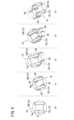
図3は、装軌車両10の旋回動作の第1例を時系列に示す動作説明図である。第1例は、移動制御(図2のステップS6)において、移動制御部48が装軌車両10を前進させる制御例である。[3 Operation of the Tracked Vehicle 10]
[3-1 First Example]
3 is an explanatory diagram showing a first example of a turning operation of the tracked
時点t0~時点t1において、旋回制御部46は、装軌車両10を左回り(矢印A)に超信地旋回させる(図2のステップS1)。装軌車両10の旋回中に、クローラ12の前半体の左横とクローラ12の後半体の右横には土塊56が形成される。図3において、ドットが付された範囲が土塊56である。Between time t0 and time t1, the turning
時点t1において、旋回制御部46は、第1旋回角度が分割角度に達したと判定する(図2のステップS4:YES)。旋回制御部46は、旋回制御を一時中断する(図2のステップS5)。At time t1, the turning
時点t1~時点t2において、移動制御部48は、装軌車両10を所定距離だけ前方(矢印B)に移動させる。(図2のステップS6)。装軌車両10がクローラ長Lの半分L/2以上前進することによって、クローラ12の前半体は、左横に土塊56がない位置に移動することができ、クローラ12の後半体は、右横に土塊56がない位置に移動することができる。一方、装軌車両10の移動距離が長すぎると、装軌車両10の旋回角度が目標角度に達するまでに、装軌車両10の旋回中心の位置ずれが大きくなる。旋回中心の位置ずれを小さくするために、所定距離は、できるだけ小さいことが好ましい。以上から、装軌車両10が1回の旋回中断時に移動する所定距離は、クローラ長Lの半分L/2以上、且つ、クローラ長L以下の長さであることが好ましい。更にいえば、所定距離は、クローラ長Lの半分L/2であることが好ましい。なお、クローラ長Lというのは、クローラ12の前端からクローラ12の後端までの長さである。Between time t1 and time t2, the
時点t2以降(時点t2、時点t3~)、旋回制御部46は、時点t0~時点t2までの制御と同じ制御を、第2旋回角度が目標角度に達するまで行う。第2旋回角度が目標角度に達した場合、旋回制御部46は旋回制御を終了する。この時点で、装軌車両10は、追従対象に向いている。走行制御部44は、装軌車両10が追従対象に追従して走行するように、各々の走行用モータ50を制御する。After time t2 (time t2, time t3, etc.), the turning
このように、第1例において、走行制御装置18(旋回制御装置)は、装軌車両10を目標角度だけ旋回させる場合に、旋回制御と移動制御とを交互に行う。言い換えると、装軌車両10は、旋回位置(旋回中心位置)を移動させながら目標角度だけ旋回する。第1例によって形成される個々の土塊56の大きさは、1箇所で目標角度だけ旋回することによって形成される土塊56の大きさよりも小さくなる。このため、走行制御装置18は、装軌車両10の旋回時に形成される土塊56の大きさを小さくすることができる。その結果として、装軌車両10の旋回時に走行用モータ50に必要なトルクは小さくなる。つまり、走行制御装置18は、第1例の動作を行うことにより、地面の荒れを少なくすることができ、また、電力の消費量を小さくすることができる。In this way, in the first example, the travel control device 18 (turning control device) alternates between turning control and movement control when turning the tracked
[3-2 第2例]
図4は、装軌車両10の旋回動作の第2例を時系列に示す動作説明図である。第2例は、移動制御部48が装軌車両10を前進させる移動制御と装軌車両10を後退させる移動制御とを交互に行う制御例である。[3-2 Second Example]
4 is an explanatory diagram showing a second example of the turning operation of the tracked
第2例での時点t0~時点t3までの動作は、第1例での時点t0~時点t3までの動作と同じである。第1例と第2例とは、時点t3~時点t4における装軌車両10の移動方向、すなわち2回目の移動制御の移動方向が相違する。第1例では、時点t3後において、移動制御部48は、装軌車両10を所定距離(クローラ長Lの半分の距離L/2)だけ前方(矢印B)に移動させる。一方、第2例では、時点t3~時点t4において、移動制御部48は、装軌車両10を所定距離(クローラ長Lの半分の距離L/2)だけ後方(矢印C)に移動させる。The operation from time t0 to time t3 in the second example is the same as the operation from time t0 to time t3 in the first example. The first and second examples differ in the movement direction of the tracked
このように、第2例では、移動制御部48は、奇数回目の移動制御(図2のステップS6)において装軌車両10を前進させ、偶数回目の移動制御(図2のステップS6)において装軌車両10を後退させる。なお、移動制御部48は、奇数回目の移動制御において装軌車両10を後退させ、偶数回目の移動制御において装軌車両10を前進させてもよい。要するに、移動制御部48は、n(nは2以上の自然数)回目の旋回中断時における装軌車両10の移動方向を、n-1回目の旋回中断時における装軌車両10の移動方向と逆方向にする。In this way, in the second example, the
なお、移動制御部48は、予め設定されて順番で、前進と後退とを行ってもよい。The
走行制御装置18は、第2例の動作を行うことにより、第1例と同じ効果を奏するだけでなく、更に旋回中心の位置ずれを小さくすることができる。また、走行制御装置18が装軌車両10の移動方向を交互に切り換えることにより、装軌車両10は、n回目の移動時に直前に形成された土塊56の一部の上を移動する。すると、土塊56は踏み固められる。つまり、走行制御装置18は、第2例の動作を行うことにより、第1例よりも更に地面の荒れを少なくすることができる。更に、走行制御装置18は、装軌車両10をクローラ12の幅Dに相当する角度だけ旋回させ、前回の旋回後の前後移動方向と逆方向に前後移動させることが可能である。これによって、装軌車両10は、すでにクローラ12が踏み固めた場所とは重ならないように移動することが可能となる。このように、走行制御装置18は、効率よく地面の荒れを少なくすることができる。By performing the operation of the second example, the
[4 その他の実施形態]
上述した実施形態の装軌車両10は、追従対象(人)に追従して前進する。しかし、装軌車両10は、予め設定された走行ルートに沿って前進してもよい。この場合、目標認識部38は、走行ルートを認識する。動作決定部42は、目標認識部38が認識した走行ルートと、位置認識部40が認識した装軌車両10の位置及び向きとに基づいて、装軌車両10が走行すべき方向、装軌車両10が旋回すべき角度等を決定する。[4 Other embodiments]
The tracked
これとは別に、装軌車両10は、旋回制御以外の制御をユーザが行い、旋回制御のみを自動で行う有人車両であってもよい。また、装軌車両10は、ユーザが遠隔地から操作する遠隔操作車両であってもよい。装軌車両10が有人車両又は遠隔操作車両である場合、例えば、ユーザが旋回の指示(ボタン操作等)を行うことによって、旋回制御部46及び移動制御部48は、図2で示される自動制御を行う。Alternatively, the tracked
位置認識部40は、装軌車両10の旋回角度を算出する場合に、慣性計測装置28の計測データを使用しなくてもよい。例えば、位置認識部40は、旋回時間、動力源の負荷(上記実施形態では走行用モータ50の電流値)等に基づいて装軌車両10の旋回角度を算出することも可能である。The
分割角度は、可変地であってもよい。例えば、動作決定部42は、目標角度を所定等分に分割することによって、分割角度を算出してもよい。The division angle may be variable. For example, the
分割角度は、装軌車両10が作業を行う場所の土壌の状態に応じて設定されてもよい。例えば、柔らかい土壌においては、小さな分割角度が設定される。また、硬い土壌においては、大きな分割角度を設定することが可能である。The division angle may be set according to the soil conditions at the location where the tracked
[5 実施形態から得られる発明]
上記実施形態から把握しうる発明について、以下に記載する。[5. Invention Obtained from the Embodiments]
The invention that can be understood from the above embodiment will be described below.
本発明の第1の態様は、左右に走行用のクローラ(12)を備えた装軌車両(10)の自動旋回を行う旋回制御装置(18)であって、前記装軌車両の旋回角度が目標旋回角度になるまで、左右の前記クローラを制御して、前記装軌車両を超信地旋回又は信地旋回させる旋回制御部(46)と、前記装軌車両が所定の分割角度だけ旋回する度に前記旋回制御部による超信地旋回又は信地旋回を一時中断させて、左右の前記クローラを制御して、前記装軌車両を所定距離だけ前進又は後退させる移動制御部(48)とを備える。The first aspect of the present invention is a turning control device (18) that automatically turns a tracked vehicle (10) equipped with left and right crawlers (12) for travel, and includes a turning control unit (46) that controls the left and right crawlers to make the tracked vehicle make a pivot turn or a yaw turn until the turning angle of the tracked vehicle reaches a target turning angle, and a movement control unit (48) that temporarily suspends the pivot turn or yaw turn by the turning control unit each time the tracked vehicle turns a predetermined division angle, and controls the left and right crawlers to move the tracked vehicle forward or backward a predetermined distance.
第1の態様において、前記移動制御部は、前記クローラの前端から前記クローラの後端までの長さであるクローラ長(L)の半分以上、且つ、前記クローラ長以下の長さと等しい距離だけ前記装軌車両を前進又は後退させてもよい。In a first aspect, the movement control unit may move the tracked vehicle forward or backward a distance equal to or greater than half the crawler length (L), which is the length from the front end of the crawler to the rear end of the crawler, and equal to or less than the crawler length.
第1の態様において、前記移動制御部は、前記装軌車両を前記クローラ長の半分の長さと等しい距離だけ前進又は後退させてもよい。In a first aspect, the movement control unit may move the tracked vehicle forward or backward a distance equal to half the crawler length.
第1の態様において、前記移動制御部は、n(nは2以上の自然数)回目の旋回中断時における前記装軌車両の移動方向を、n-1回目の旋回中断時における前記装軌車両の移動方向と逆方向にしてもよい。In a first aspect, the movement control unit may set the movement direction of the tracked vehicle at the nth (n is a natural number equal to or greater than 2) turning interruption to be opposite to the movement direction of the tracked vehicle at the n-1th turning interruption.
第1の態様において、前記装軌車両の動力源は、電動機(50)であってもよい。In a first embodiment, the power source of the tracked vehicle may be an electric motor (50).
第1の態様において、前記旋回制御部は、前記装軌車両を超信地旋回させる場合に、前記分割角度を、(前記クローラの幅(D)に相当する旋回円弧の長さ)/(超信地旋回の旋回半径)にしてもよい。In a first aspect, when the tracked vehicle is made to make a pivot turn, the turning control unit may set the division angle to (length of the turning arc equivalent to the width (D) of the crawler)/(turning radius of the pivot turn).
第1の態様において、前記分割角度は、前記装軌車両が作業を行う場所の土壌の状態に応じて設定されてもよい。In the first aspect, the division angle may be set according to the soil conditions at the location where the tracked vehicle is performing work.
本発明の第2の態様は、左右に走行用のクローラを備えた装軌車両の自動旋回制御を、コンピュータを用いて行う旋回制御方法であって、前記装軌車両の旋回角度が目標旋回角度になるまで、左右の前記クローラを制御して、前記装軌車両を超信地旋回又は信地旋回させる旋回工程と、前記装軌車両が所定の分割角度だけ旋回する度に前記旋回工程における超信地旋回又は信地旋回を一時中断させて、左右の前記クローラを制御して、前記装軌車両を所定距離だけ前進又は後退させる移動工程とを行う。The second aspect of the present invention is a turning control method that uses a computer to automatically control the turning of a tracked vehicle equipped with crawlers for travel on the left and right, and includes a turning process that controls the left and right crawlers to make the tracked vehicle make a pivot turn or a yaw turn until the turning angle of the tracked vehicle reaches a target turning angle, and a moving process that temporarily suspends the pivot turn or yaw turn in the turning process each time the tracked vehicle turns a predetermined division angle, and controls the left and right crawlers to move the tracked vehicle forward or backward a predetermined distance.
10…装軌車両 12…クローラ
18…走行制御装置(旋回制御装置) 46…旋回制御部
48…移動制御部 50…走行用モータ(電動機)10: Tracked vehicle 12: Crawler 18: Travel control device (turning control device) 46: Turning control unit 48: Movement control unit 50: Travel motor (electric motor)
Claims (8)
Translated fromJapanese前記装軌車両の旋回角度が目標旋回角度になるまで、左右の前記クローラを制御して、前記装軌車両を超信地旋回又は信地旋回させる旋回制御部と、
前記装軌車両が所定の分割角度だけ旋回する度に前記旋回制御部による超信地旋回又は信地旋回を一時中断させて、左右の前記クローラを制御して、前記装軌車両を所定距離だけ前進又は後退させる移動制御部とを備える、旋回制御装置。 A turning control device for automatically turning a tracked vehicle having crawlers for traveling on the left and right sides,
a turning control unit that controls the left and right crawlers to make the tracked vehicle perform a pivot turn or a yaw turn until the turning angle of the tracked vehicle reaches a target turning angle;
A turning control device comprising: a movement control unit that temporarily suspends the pivot turning or swivel turning performed by the turning control unit each time the tracked vehicle turns by a predetermined divided angle, and controls the left and right crawlers to move the tracked vehicle forward or backward by a predetermined distance.
前記移動制御部は、前記クローラの前端から前記クローラの後端までの長さであるクローラ長の半分以上、且つ、前記クローラ長以下の長さと等しい距離だけ前記装軌車両を前方又は後方に移動させる、旋回制御装置。 The turning control device according to claim 1,
The movement control unit is a turning control device that moves the tracked vehicle forward or backward a distance equal to or greater than half the crawler length, which is the length from the front end of the crawler to the rear end of the crawler, and less than or equal to the crawler length.
前記移動制御部は、前記装軌車両を前記クローラ長の半分の長さと等しい距離だけ前方又は後方に移動させる、旋回制御装置。 The turning control device according to claim 2,
The movement control unit is a turning control device that moves the tracked vehicle forward or backward a distance equal to half the crawler length.
前記移動制御部は、n(nは2以上の自然数)回目の旋回中断時における前記装軌車両の移動方向を、n-1回目の旋回中断時における前記装軌車両の移動方向と逆方向にする、旋回制御装置。 The turning control device according to any one of claims 1 to 3,
The movement control unit is a turning control device that changes the movement direction of the tracked vehicle at the nth (n is a natural number greater than or equal to 2) turning interruption to the opposite direction to the movement direction of the tracked vehicle at the n-1th turning interruption.
前記装軌車両の動力源は、電動機である、旋回制御装置。 The turning control device according to any one of claims 1 to 4,
A turning control device in which the power source of the tracked vehicle is an electric motor.
前記旋回制御部は、前記装軌車両を超信地旋回させる場合に、前記分割角度を、(前記クローラの幅に相当する旋回円弧の長さ)/(超信地旋回の旋回半径)にする、旋回制御装置。 The turning control device according to any one of claims 1 to 5,
The turning control unit is a turning control device that sets the divided angle to (length of turning arc corresponding to width of the crawler) / (turning radius of the pivot turn) when the tracked vehicle is made to make a pivot turn.
前記分割角度は、前記装軌車両が作業を行う場所の土壌の状態に応じて設定される、旋回制御装置。 The turning control device according to any one of claims 1 to 5,
A turning control device in which the division angle is set according to the soil conditions at the location where the tracked vehicle is working.
前記装軌車両の旋回角度が目標旋回角度になるまで、左右の前記クローラを制御して、前記装軌車両を超信地旋回又は信地旋回させる旋回工程と、
前記装軌車両が所定の分割角度だけ旋回する度に前記旋回工程における超信地旋回又は信地旋回を一時中断させて、左右の前記クローラを制御して、前記装軌車両を所定距離だけ前進又は後退させる移動工程とを行う、旋回制御方法。 A method for automatically controlling the turning of a tracked vehicle having crawlers for traveling on the left and right sides, comprising the steps of:
a turning process for controlling the left and right crawlers to perform a pivot turn or a yaw turn of the tracked vehicle until the turning angle of the tracked vehicle reaches a target turning angle;
A turning control method comprising: a moving process in which the pivot turning or swivel turning in the turning process is temporarily interrupted each time the tracked vehicle turns by a predetermined divided angle, and the left and right crawlers are controlled to move the tracked vehicle forward or backward by a predetermined distance.
Priority Applications (1)
| Application Number | Priority Date | Filing Date | Title |
|---|---|---|---|
| JP2022032334AJP7704430B2 (en) | 2022-03-03 | 2022-03-03 | Swing control device and method |
Applications Claiming Priority (1)
| Application Number | Priority Date | Filing Date | Title |
|---|---|---|---|
| JP2022032334AJP7704430B2 (en) | 2022-03-03 | 2022-03-03 | Swing control device and method |
Publications (2)
| Publication Number | Publication Date |
|---|---|
| JP2023128170A JP2023128170A (en) | 2023-09-14 |
| JP7704430B2true JP7704430B2 (en) | 2025-07-08 |
Family
ID=87972079
Family Applications (1)
| Application Number | Title | Priority Date | Filing Date |
|---|---|---|---|
| JP2022032334AActiveJP7704430B2 (en) | 2022-03-03 | 2022-03-03 | Swing control device and method |
Country Status (1)
| Country | Link |
|---|---|
| JP (1) | JP7704430B2 (en) |
Citations (3)
| Publication number | Priority date | Publication date | Assignee | Title |
|---|---|---|---|---|
| US20100219004A1 (en) | 2006-06-08 | 2010-09-02 | Mackenzie Roderick | Snow traction unit for vehicles |
| WO2020111088A1 (en) | 2018-11-30 | 2020-06-04 | 株式会社クボタ | Automatic steering system, automatic steering method, and automatic steering program |
| JP2021083391A (en) | 2019-11-29 | 2021-06-03 | 株式会社クボタ | Automatic travel control system and combine |
Family Cites Families (1)
| Publication number | Priority date | Publication date | Assignee | Title |
|---|---|---|---|---|
| JPH10227316A (en)* | 1997-02-18 | 1998-08-25 | Exedy Corp | Twin clutch |
- 2022
- 2022-03-03JPJP2022032334Apatent/JP7704430B2/enactiveActive
Patent Citations (3)
| Publication number | Priority date | Publication date | Assignee | Title |
|---|---|---|---|---|
| US20100219004A1 (en) | 2006-06-08 | 2010-09-02 | Mackenzie Roderick | Snow traction unit for vehicles |
| WO2020111088A1 (en) | 2018-11-30 | 2020-06-04 | 株式会社クボタ | Automatic steering system, automatic steering method, and automatic steering program |
| JP2021083391A (en) | 2019-11-29 | 2021-06-03 | 株式会社クボタ | Automatic travel control system and combine |
Also Published As
| Publication number | Publication date |
|---|---|
| JP2023128170A (en) | 2023-09-14 |
Similar Documents
| Publication | Publication Date | Title |
|---|---|---|
| CN107914767B (en) | Steering assist device | |
| CN102171084B (en) | System equipped with assisting controller for assisting system operator, control operation assisting device, control operation assisting method, driving operation assisting device, and driving operation assisting method | |
| CN109154817B (en) | Automatic traveling work vehicle | |
| JP5973609B1 (en) | Control equipment for unmanned work vehicles | |
| JP7038536B2 (en) | Work vehicle | |
| EP3900505B1 (en) | Control device for automatic travel work vehicle | |
| US20230125422A1 (en) | Control apparatus and control method as well as computer program | |
| JP2020032828A (en) | Vehicular steering device | |
| JP6382761B2 (en) | Self-propelled vehicle | |
| JP2013075600A (en) | Vehicle travel control device | |
| JP2017117257A (en) | Autonomous traveling system for work vehicles | |
| WO2016114948A1 (en) | System and method for controlling dollies | |
| JP7704430B2 (en) | Swing control device and method | |
| JPH1178938A (en) | Vehicle steering reaction control system | |
| JP7704429B2 (en) | Swing control device and method | |
| JP4248335B2 (en) | Vehicle travel support device | |
| JP6776543B2 (en) | Vehicle control system | |
| JP2707546B2 (en) | Vehicle steering control device | |
| JP3022354B2 (en) | Method for causing a mobile vehicle to execute a motion combining a combination of arbitrary parallel movement and arbitrary rotation | |
| CN119847134A (en) | Vector control method and device for steering wheel chassis | |
| US20240182107A1 (en) | Steering angle error monitoring | |
| JP2004171430A (en) | Carrying vehicle | |
| CN113914406A (en) | Electric loader path tracking system and control method | |
| JP2021149118A (en) | Mobile body control device, mobile body, and mobile body control method | |
| JP2766334B2 (en) | Automatic driving control system for vehicles |
Legal Events
| Date | Code | Title | Description |
|---|---|---|---|
| A621 | Written request for application examination | Free format text:JAPANESE INTERMEDIATE CODE: A621 Effective date:20240913 | |
| A977 | Report on retrieval | Free format text:JAPANESE INTERMEDIATE CODE: A971007 Effective date:20250522 | |
| TRDD | Decision of grant or rejection written | ||
| A01 | Written decision to grant a patent or to grant a registration (utility model) | Free format text:JAPANESE INTERMEDIATE CODE: A01 Effective date:20250603 | |
| A61 | First payment of annual fees (during grant procedure) | Free format text:JAPANESE INTERMEDIATE CODE: A61 Effective date:20250619 | |
| R150 | Certificate of patent or registration of utility model | Ref document number:7704430 Country of ref document:JP Free format text:JAPANESE INTERMEDIATE CODE: R150 |