JP7704099B2 - Constant Velocity Joint - Google Patents
Constant Velocity JointDownload PDFInfo
- Publication number
- JP7704099B2 JP7704099B2JP2022125882AJP2022125882AJP7704099B2JP 7704099 B2JP7704099 B2JP 7704099B2JP 2022125882 AJP2022125882 AJP 2022125882AJP 2022125882 AJP2022125882 AJP 2022125882AJP 7704099 B2JP7704099 B2JP 7704099B2
- Authority
- JP
- Japan
- Prior art keywords
- ball
- groove
- ball groove
- groove portion
- race
- Prior art date
- Legal status (The legal status is an assumption and is not a legal conclusion. Google has not performed a legal analysis and makes no representation as to the accuracy of the status listed.)
- Active
Links
Images


Classifications
- F—MECHANICAL ENGINEERING; LIGHTING; HEATING; WEAPONS; BLASTING
- F16—ENGINEERING ELEMENTS AND UNITS; GENERAL MEASURES FOR PRODUCING AND MAINTAINING EFFECTIVE FUNCTIONING OF MACHINES OR INSTALLATIONS; THERMAL INSULATION IN GENERAL
- F16D—COUPLINGS FOR TRANSMITTING ROTATION; CLUTCHES; BRAKES
- F16D3/00—Yielding couplings, i.e. with means permitting movement between the connected parts during the drive
- F16D3/16—Universal joints in which flexibility is produced by means of pivots or sliding or rolling connecting parts
- F16D3/20—Universal joints in which flexibility is produced by means of pivots or sliding or rolling connecting parts one coupling part entering a sleeve of the other coupling part and connected thereto by sliding or rolling members
- F16D3/22—Universal joints in which flexibility is produced by means of pivots or sliding or rolling connecting parts one coupling part entering a sleeve of the other coupling part and connected thereto by sliding or rolling members the rolling members being balls, rollers, or the like, guided in grooves or sockets in both coupling parts
- F16D3/223—Universal joints in which flexibility is produced by means of pivots or sliding or rolling connecting parts one coupling part entering a sleeve of the other coupling part and connected thereto by sliding or rolling members the rolling members being balls, rollers, or the like, guided in grooves or sockets in both coupling parts the rolling members being guided in grooves in both coupling parts
- F16D3/2237—Universal joints in which flexibility is produced by means of pivots or sliding or rolling connecting parts one coupling part entering a sleeve of the other coupling part and connected thereto by sliding or rolling members the rolling members being balls, rollers, or the like, guided in grooves or sockets in both coupling parts the rolling members being guided in grooves in both coupling parts where the grooves are composed of radii and adjoining straight lines, i.e. undercut free [UF] type joints
- F—MECHANICAL ENGINEERING; LIGHTING; HEATING; WEAPONS; BLASTING
- F16—ENGINEERING ELEMENTS AND UNITS; GENERAL MEASURES FOR PRODUCING AND MAINTAINING EFFECTIVE FUNCTIONING OF MACHINES OR INSTALLATIONS; THERMAL INSULATION IN GENERAL
- F16D—COUPLINGS FOR TRANSMITTING ROTATION; CLUTCHES; BRAKES
- F16D3/00—Yielding couplings, i.e. with means permitting movement between the connected parts during the drive
- F16D3/16—Universal joints in which flexibility is produced by means of pivots or sliding or rolling connecting parts
- F16D3/20—Universal joints in which flexibility is produced by means of pivots or sliding or rolling connecting parts one coupling part entering a sleeve of the other coupling part and connected thereto by sliding or rolling members
- F16D3/22—Universal joints in which flexibility is produced by means of pivots or sliding or rolling connecting parts one coupling part entering a sleeve of the other coupling part and connected thereto by sliding or rolling members the rolling members being balls, rollers, or the like, guided in grooves or sockets in both coupling parts
- F16D3/223—Universal joints in which flexibility is produced by means of pivots or sliding or rolling connecting parts one coupling part entering a sleeve of the other coupling part and connected thereto by sliding or rolling members the rolling members being balls, rollers, or the like, guided in grooves or sockets in both coupling parts the rolling members being guided in grooves in both coupling parts
- F16D3/224—Universal joints in which flexibility is produced by means of pivots or sliding or rolling connecting parts one coupling part entering a sleeve of the other coupling part and connected thereto by sliding or rolling members the rolling members being balls, rollers, or the like, guided in grooves or sockets in both coupling parts the rolling members being guided in grooves in both coupling parts the groove centre-lines in each coupling part lying on a sphere
- F—MECHANICAL ENGINEERING; LIGHTING; HEATING; WEAPONS; BLASTING
- F16—ENGINEERING ELEMENTS AND UNITS; GENERAL MEASURES FOR PRODUCING AND MAINTAINING EFFECTIVE FUNCTIONING OF MACHINES OR INSTALLATIONS; THERMAL INSULATION IN GENERAL
- F16D—COUPLINGS FOR TRANSMITTING ROTATION; CLUTCHES; BRAKES
- F16D3/00—Yielding couplings, i.e. with means permitting movement between the connected parts during the drive
- F16D3/16—Universal joints in which flexibility is produced by means of pivots or sliding or rolling connecting parts
- F16D3/20—Universal joints in which flexibility is produced by means of pivots or sliding or rolling connecting parts one coupling part entering a sleeve of the other coupling part and connected thereto by sliding or rolling members
- F16D3/22—Universal joints in which flexibility is produced by means of pivots or sliding or rolling connecting parts one coupling part entering a sleeve of the other coupling part and connected thereto by sliding or rolling members the rolling members being balls, rollers, or the like, guided in grooves or sockets in both coupling parts
- F16D3/223—Universal joints in which flexibility is produced by means of pivots or sliding or rolling connecting parts one coupling part entering a sleeve of the other coupling part and connected thereto by sliding or rolling members the rolling members being balls, rollers, or the like, guided in grooves or sockets in both coupling parts the rolling members being guided in grooves in both coupling parts
- F16D2003/22303—Details of ball cages
- F—MECHANICAL ENGINEERING; LIGHTING; HEATING; WEAPONS; BLASTING
- F16—ENGINEERING ELEMENTS AND UNITS; GENERAL MEASURES FOR PRODUCING AND MAINTAINING EFFECTIVE FUNCTIONING OF MACHINES OR INSTALLATIONS; THERMAL INSULATION IN GENERAL
- F16D—COUPLINGS FOR TRANSMITTING ROTATION; CLUTCHES; BRAKES
- F16D3/00—Yielding couplings, i.e. with means permitting movement between the connected parts during the drive
- F16D3/16—Universal joints in which flexibility is produced by means of pivots or sliding or rolling connecting parts
- F16D3/20—Universal joints in which flexibility is produced by means of pivots or sliding or rolling connecting parts one coupling part entering a sleeve of the other coupling part and connected thereto by sliding or rolling members
- F16D3/22—Universal joints in which flexibility is produced by means of pivots or sliding or rolling connecting parts one coupling part entering a sleeve of the other coupling part and connected thereto by sliding or rolling members the rolling members being balls, rollers, or the like, guided in grooves or sockets in both coupling parts
- F16D3/223—Universal joints in which flexibility is produced by means of pivots or sliding or rolling connecting parts one coupling part entering a sleeve of the other coupling part and connected thereto by sliding or rolling members the rolling members being balls, rollers, or the like, guided in grooves or sockets in both coupling parts the rolling members being guided in grooves in both coupling parts
- F16D2003/22306—Universal joints in which flexibility is produced by means of pivots or sliding or rolling connecting parts one coupling part entering a sleeve of the other coupling part and connected thereto by sliding or rolling members the rolling members being balls, rollers, or the like, guided in grooves or sockets in both coupling parts the rolling members being guided in grooves in both coupling parts having counter tracks, i.e. ball track surfaces which diverge in opposite directions
- F—MECHANICAL ENGINEERING; LIGHTING; HEATING; WEAPONS; BLASTING
- F16—ENGINEERING ELEMENTS AND UNITS; GENERAL MEASURES FOR PRODUCING AND MAINTAINING EFFECTIVE FUNCTIONING OF MACHINES OR INSTALLATIONS; THERMAL INSULATION IN GENERAL
- F16D—COUPLINGS FOR TRANSMITTING ROTATION; CLUTCHES; BRAKES
- F16D3/00—Yielding couplings, i.e. with means permitting movement between the connected parts during the drive
- F16D3/16—Universal joints in which flexibility is produced by means of pivots or sliding or rolling connecting parts
- F16D3/20—Universal joints in which flexibility is produced by means of pivots or sliding or rolling connecting parts one coupling part entering a sleeve of the other coupling part and connected thereto by sliding or rolling members
- F16D3/22—Universal joints in which flexibility is produced by means of pivots or sliding or rolling connecting parts one coupling part entering a sleeve of the other coupling part and connected thereto by sliding or rolling members the rolling members being balls, rollers, or the like, guided in grooves or sockets in both coupling parts
- F16D3/223—Universal joints in which flexibility is produced by means of pivots or sliding or rolling connecting parts one coupling part entering a sleeve of the other coupling part and connected thereto by sliding or rolling members the rolling members being balls, rollers, or the like, guided in grooves or sockets in both coupling parts the rolling members being guided in grooves in both coupling parts
- F16D2003/22309—Details of grooves
- Y—GENERAL TAGGING OF NEW TECHNOLOGICAL DEVELOPMENTS; GENERAL TAGGING OF CROSS-SECTIONAL TECHNOLOGIES SPANNING OVER SEVERAL SECTIONS OF THE IPC; TECHNICAL SUBJECTS COVERED BY FORMER USPC CROSS-REFERENCE ART COLLECTIONS [XRACs] AND DIGESTS
- Y10—TECHNICAL SUBJECTS COVERED BY FORMER USPC
- Y10S—TECHNICAL SUBJECTS COVERED BY FORMER USPC CROSS-REFERENCE ART COLLECTIONS [XRACs] AND DIGESTS
- Y10S464/00—Rotary shafts, gudgeons, housings, and flexible couplings for rotary shafts
- Y10S464/904—Homokinetic coupling
- Y10S464/906—Torque transmitted via radially spaced balls
Landscapes
- Engineering & Computer Science (AREA)
- General Engineering & Computer Science (AREA)
- Mechanical Engineering (AREA)
- Rolling Contact Bearings (AREA)
- Transmission Devices (AREA)
Description
Translated fromJapanese本発明は、車両に搭載される等速ジョイントに関する。The present invention relates to a constant velocity joint mounted on a vehicle.
内周面に複数の外側ボール溝が設けられたカップ状のアウタレースと、外周面に複数の内側ボール溝が設けられて、前記アウタケースの内側に配設されるインナレースと、前記外側ボール溝と前記内側ボール溝との間に介在させられてトルク伝達する複数のボールと、複数のボールを保持するケージと、を備える、等速ジョイントが知られている。特許文献1に記載の等速ジョイントがそれである。There is known a constant velocity joint that includes a cup-shaped outer race with multiple outer ball grooves on its inner circumferential surface, an inner race with multiple inner ball grooves on its outer circumferential surface and disposed inside the outer case, multiple balls that are interposed between the outer ball grooves and the inner ball grooves to transmit torque, and a cage that holds the multiple balls. The constant velocity joint described in
特許文献1には、前記アウタレースおよび前記インナレースの各中心線が一直線上位置するジョイント角がゼロ(deg)の基準状態で、前記外側ボール溝とボールとの接線および前記内側ボール溝とボールとの接線とが交差することで形成される開放角が、前記アウタレースのカップ開口側に向かって開く第1溝部と、前記開放角が前記アウタレースのカップ奥側(カップ底側)に向かって開く第2溝部と、を有する構造が開示されている。
ところで、外側ボール溝および内側ボール溝がボールを押し出す力は、ボールと各ボール溝との間にかかる荷重(ボール溝荷重)と前記開放角との積(ボール溝荷重×開放角)で決まる。特許文献1に記載されるような等速ジョイントでは、高ジョイント角領域において、第2溝部の開放角がゼロ(deg)を跨いだとき、各ボール溝がボールを押し出せなくなってボールがロックする。このとき、ボールにかかる荷重が大きくなると、ボールのロック開放時に異音および振動が発生する虞がある。The force with which the outer ball groove and inner ball groove push out the ball is determined by the product of the load (ball groove load) between the ball and each ball groove and the opening angle (ball groove load x opening angle). In a constant velocity joint such as that described in
本発明は、以上の事情を背景として為されたものであり、その目的とするところは、ボール溝に挟まれたボールがロック状態から開放されたときに発生する異音および振動を抑制できる等速ジョイントを提供することにある。The present invention was made against the background of the above circumstances, and its purpose is to provide a constant velocity joint that can suppress abnormal noise and vibrations that occur when the balls sandwiched in the ball grooves are released from a locked state.
第1発明の要旨とするところは、(a)内周面に複数の外側ボール溝が設けられたカップ状のアウタレースと、外周面に複数の内側ボール溝が設けられて、前記アウタレースの内側に配設されるインナレースと、前記外側ボール溝と前記内側ボール溝との間に介在させられてトルク伝達する複数のボールと、を備え、且つ、前記アウタレースおよび前記インナレースの各中心線が一直線上に位置するジョイント角がゼロ度の基準状態で、前記外側ボール溝と前記ボールとの接線および前記内側ボール溝と前記ボールとの接線が交差することで形成される開放角が前記アウタレースのカップ開口側に向かって開く第1溝部と、前記開放角が前記アウタレースのカップ奥側に向かって開く第2溝部と、を有し、前記アウタレースの中心線と前記インナレースの中心線とが交差して形成されるジョイント角が所定角以上になると、前記第2溝部における前記開放角がゼロを跨ぐように構成されている等速ジョイントであって、(b)前記第2溝部を構成する前記アウタレースの前記外側ボール溝を前記アウタレースの中心線に対して垂直な面で切断したときの前記外側ボール溝の円弧の半径が、前記第1溝部を構成する前記外側ボール溝の円弧の半径に比べて大きく形成されている、及び、(c)前記第2溝部を構成する前記インナレースの前記内側ボール溝を前記インナレースの中心線に対して垂直な面で切断したときの前記内側ボール溝の円弧の半径が、前記第1溝部を構成する前記内側ボール溝の円弧の半径に比べて大きく形成されている、の少なくとも一方を満たすことを特徴とする。 The gist of a first invention is a cup-shaped outer race having a plurality of outer ball grooves formed on an inner circumferential surface thereof, an inner race having a plurality of inner ball grooves formed on an outer circumferential surface thereof and disposed inside the outer race, and a plurality of balls interposed between the outer ball groove and the inner ball groove to transmit torque, the cup having a first groove portion where an opening angle formed by an intersection of a tangent between the outer ball groove and the ball and a tangent between the inner ball groove and the ball opens toward a cup opening side of the outer race, and a second groove portion where the opening angle opens toward a cup depth side of the outer race, the opening angle being formed by an intersection of a tangent between the outer race center line and the inner ball groove in a reference state where a joint angle of zero degrees is zerodegrees and the center lines of the outer race and the inner race are aligned in a straight line. and (c)a radius of an arc of the inner ball groove of the inner race that constitutes the second groove portion is larger than a radius of an arc of the inner ball groove of the first groove portion when the inner ball groove of the inner race that constitutes the second groove portion is cut with a plane perpendicular to the center line of the outer race.
第2発明の要旨とするところは、第1発明において、(a)前記第2溝部を構成する前記アウタレースの前記外側ボール溝を前記アウタレースの中心線に対して垂直な面で切断したときの、前記外側ボール溝の円弧の半径が、前記第1溝部を構成する前記外側ボール溝の円弧の半径に比べて大きく形成されていると共に、(b)前記第2溝部を構成する前記インナレースの前記内側ボール溝を前記インナレースの中心線に対して垂直な面で切断したときの前記内側ボール溝の円弧の半径が、前記第1溝部を構成する前記内側ボール溝の円弧の半径に比べて大きく形成されていることを特徴とする。The gist of the second invention is that in the first invention, (a) the radius of the arc of the outer ball groove of the outer race constituting the second groove portion is larger than the radius of the arc of the outer ball groove of the first groove portion when the outer ball groove of the outer race is cut on a plane perpendicular to the center line of the outer race, and (b) the radius of the arc of the inner ball groove of the inner race constituting the second groove portion is cut on a plane perpendicular to the center line of the inner race when the inner ball groove of the inner race constituting the second groove portion is cut on a plane perpendicular to the center line of the inner race, and is larger than the radius of the arc of the inner ball groove of the first groove portion.
第1発明によれば、第2溝部を構成するアウタレースの外側ボール溝をアウタレースの中心線に対して垂直な面で切断したときの外側ボール溝の円弧の半径が、第1溝部を構成する外側ボール溝の円弧の半径に比べて大きく形成されている、及び、第2溝部を構成するインナレースの内側ボール溝をインナレースの中心線に対して垂直な面で切断したときの内側ボール溝の円弧の半径が、第1溝部を構成する内側ボール溝の円弧の半径に比べて大きく形成されている、の少なくとも一方を満たす為、等速ジョイントに高トルクがかかり、ボールにかかる荷重が大きくなる状態下において、第2溝部側のボールにかかる荷重を低減することができる。その結果、第2溝部のボールのロック開放時に発生する異音および振動を抑制することができる。
また、第2溝部は、ジョイント角が所定角以上になると、第2溝部における開放角がゼロを跨ぐ為、開放角がゼロを含む範囲において第2溝部のボールがロックする。このとき、等速ジョイントにかかるトルクが高トルクの状態であっても、第2溝部側のボールにかかる荷重が低減されることで、第2溝部のボールのロック開放時に発生する異音および振動を抑制することができる。 According to the first invention, at least one of the following is satisfied: when the outer ball groove of the outer race constituting the second groove portion is cut along a plane perpendicular to the centerline of the outer race, the radius of the arc of the outer ball groove is larger than the radius of the arc of the outer ball groove constituting the first groove portion; and when the inner ball groove of the inner race constituting the second groove portion is cut along a plane perpendicular to the centerline of the inner race, the radius of the arc of the inner ball groove is larger than the radius of the arc of the inner ball groove constituting the first groove portion, so that when a high torque is applied to the constant velocity joint and the load on the ball is large, the load on the ball in the second groove portion can be reduced. As a result, abnormal noise and vibration generated when the ball in the second groove portion is unlocked can be suppressed.
Furthermore, when the joint angle becomes equal to or greater than a predetermined angle, the opening angle in the second groove portion crosses zero, and the ball in the second groove portion locks when the opening angle is in a range that includes zero. At this time, even if the torque applied to the constant velocity joint is high, the load applied to the ball on the second groove portion side is reduced, thereby suppressing abnormal noise and vibrations that occur when the ball in the second groove portion is unlocked.
第2発明によれば、第2溝部の外側ボール溝の円弧の半径が、第1溝部の外側ボール溝の円弧の半径よりも大きいと共に、第2溝部の内側ボール溝の円弧の半径が、第1溝部の内側ボール溝の円弧の半径よりも大きい為、等速ジョイントに高トルクがかかったとき、第2溝部側のボールにかかる荷重を効果的に低減することができる。According to the second invention, the radius of the arc of the outer ball groove of the second groove portion is larger than the radius of the arc of the outer ball groove of the first groove portion, and the radius of the arc of the inner ball groove of the second groove portion is larger than the radius of the arc of the inner ball groove of the first groove portion. Therefore, when a high torque is applied to the constant velocity joint, the load applied to the ball on the second groove portion side can be effectively reduced.
以下、本発明の実施例を図面を参照しつつ詳細に説明する。なお、以下の実施例において図は適宜簡略化或いは変形されており、各部の寸法比および形状等は必ずしも正確に描かれていない。The following describes in detail the embodiments of the present invention with reference to the drawings. Note that in the following embodiments, the drawings have been simplified or modified as appropriate, and the dimensional ratios and shapes of each part are not necessarily drawn accurately.
図1は、本発明が適用された車両の等速ジョイント10の内部構造を示す組立図(斜視図)である。等速ジョイント10は、2つの回転軸の間に設けられ、これら2つの回転軸のなす角度(ジョイント角)が変化した場合であっても、これら回転軸間で回転を伝達する、よく知られた等速自在継手である。Figure 1 is an assembly diagram (perspective view) showing the internal structure of a
等速ジョイント10は、カップ状に形成されたアウタレース12と、アウタレース12の内側に配設されるインナレース14と、アウタレース12とインナレース14との間に介在されてトルク伝達を行う複数(本実施例では6個)のボール16と、これら複数のボール16を、アウタレース12の後述する外側ボール溝22およびインナレース14の後述する内側ボール溝24から脱落不能に保持するケージ18と、を含んで構成されている。The
アウタレース12は、アウタレース12に連結されている回転軸20とともに一体回転可能に設けられている。アウタレース12は、回転軸20が連結されている部位に対して反対側が開口するカップ状に形成されている。アウタレース12のカップ状に形成された部位の内周面12a(図3参照)には、ボール16と同じ数の複数(本実施例では6本)の外側ボール溝22が設けられている。外側ボール溝22は、アウタレース12のカップ形状の開口側からカップ形状の奥側(又はカップ形状の底側)に向かって、アウタレース12の中心線CL1の方向に沿って形成されている。複数の外側ボール溝22は、アウタレース12の内周面12aに等角度間隔に形成されている。The
インナレース14は、環状形状を有し、アウタレース12のカップ状に形成された部位の内側に配設されている。インナレース14は、環状形状の中心を通る中心線CL2を中心にして回転可能とされている。インナレース14の外周面14a(図3参照)には、外側ボール溝22と同じ数の複数(本実施例では6本)の内側ボール溝24が形成されている。内側ボール溝24は、中心線CL2の方向に沿って形成されている。複数の内側ボール溝24は、インナレース14の周方向で等角度間隔に形成されている。尚、インナレース14の内周面には、図示しない回転軸とスプライン嵌合するためのスプライン歯が形成されている。The
ボール16は、金属材料からなる球形状に形成されている。ボール16は、アウタレース12の外側ボール溝22とインナレース14の内側ボール溝24との間に介在させられている。ボール16は、外側ボール溝22と内側ボール溝24との間にそれぞれ1個ずつ配置されている。ボール16は、外側ボール溝22および内側ボール溝24の溝形状に沿って揺動可能(転動可能)とされている。The
ボール16は、アウタレース12およびインナレース14の一方から伝達されたトルクを他方にトルク伝達する機能を有している。ボール16は、トルク伝達時において、アウタレース12およびインナレース14とともにそれぞれの中心線CL1、CL2(以下、これらを区別しない場合には中心線CLと記載)まわりに回転する。このとき、ボール16は、等速ジョイント10のジョイント角θに応じて、外側ボール溝22および内側ボール溝24の溝形状に沿って揺動させられる。なお、ジョイント角θは、アウタレース12の中心線CL1とインナレース14の中心線CL2とが一直線上に位置する基準状態をゼロ[deg]とする、中心線CL1および中心線CL2の交差角に相当する。The
ケージ18は、円環形状に形成され、内周面および外周面が何れも滑らかな曲面状に形成されている。ケージ18は、中心線CLを中心とする径方向において、アウタレース12とインナレース14との間に介在されている。ケージ18には、ボール16を脱落不能に保持するためのポケット26が、周方向で等角度間隔に、ボール16と同じ数(本実施例では6個)だけ所形成されている。ポケット26は、ケージ18の内周面と外周面との間を貫通し、径方向外側から見ると、ケージ18の周方向に沿って長手状に伸びる矩形に形成されている。ポケット26内にボール16がそれぞれ収容されることで、各ボール16は、ケージ18によって、周方向で等角度間隔となる位置に常時保持される。The
図2は、図1の等速ジョイント10をボール16の中心および中心線CLを通る平面で切断した断面図である。図2に示す断面図は、アウタレース12の中心線CL1およびインナレース14の中心線CL2の各中心線CLが一直線上に位置する、ジョイント角θがゼロ度[0deg]である基準状態が示されている。Figure 2 is a cross-sectional view of the
図3は、図2を矢印A方向から見た状態を簡略的に示している。図3では、ケージ18が省略されている。アウタレース12の内周面12aに形成される外側ボール溝22は、第1外側ボール溝22aおよび第2外側ボール溝22bから成る。第1外側ボール溝22aと第2外側ボール溝22bとは、アウタレース12の周方向で交互に等角度間隔に配置されている。本実施例では、6本の外側ボール溝22が設けられるため、図3に示すように、3本の第1外側ボール溝22aおよび3本の第2外側ボール溝22bが、60度間隔で交互に配置されている。また、第1外側ボール溝22aに対して中心線CL1を挟んで対向する位置に、第2外側ボール溝22bが配置される。Figure 3 shows a simplified view of Figure 2 as viewed from the direction of arrow A. In Figure 3, the
インナレース14の外周面14aに形成される内側ボール溝24は、第1内側ボール溝24aおよび第2内側ボール溝24bから成る。第1内側ボール溝24aと第2内側ボール溝24bとは、インナレース14の周方向で交互に等角度間隔に配置されている。本実施例では、6本の内側ボール溝24が設けられるため、図3に示すように、3本の第1内側ボール溝24aおよび3本の第2内側ボール溝24bが、60度間隔で交互に配置されている。また、第1内側ボール溝24aに対して中心線CL2を挟んで対向する位置に、第2内側ボール溝24bが配置されている。The
第1外側ボール溝22aおよび第1内側ボール溝24aは、中心線CLを中心とする回転方向で同じ位置に配置されている。言い換えれば、第1外側ボール溝22aおよび第1内側ボール溝24aを、中心線CLを中心とする径方向に見たとき、それらが互いに重なる位置(すなわち、それらが互いに対向する位置)に配置されている。これら第1外側ボール溝22aと第1内側ボール溝24aとの間に、トルク伝達用のボール16が介在させられている。The first
第2外側ボール溝22bおよび第2内側ボール溝24bは、中心線CLを中心とする回転方向で同じ位置に配置されている。言い換えれば、第2外側ボール溝22bおよび第2内側ボール溝24bを、中心線CLを中心とする径方向に見たとき、それらが互いに重なる位置(すなわち、それらが互いに対向する位置)に配置されている。これら第2外側ボール溝22bと第2内側ボール溝24bとの間に、トルク伝達用のボール16が介在させられている。The second
ケージ18は、アウタレース12とインナレース14との間に形成される環状空間に介在され、トルク伝達時には、図2に示すジョイント中心点Oを中心にして回動させられる。The
また、第1外側ボール溝22aおよび第1内側ボール溝24aによって、ボール16を挟む第1溝部30が構成され、第2外側ボール溝22bおよび第2内側ボール溝24bによって、ボール16を挟む第2溝部32が構成されている。これら第1溝部30および第2溝部32は、図3に示すように、中心線CLを中心とする回転方向で交互に設けられている。The first
図2に示す、第1溝部30では、ジョイント角θがゼロ度[0deg]である基準状態において、第1外側ボール溝22aおよび第1内側ボール溝24aがボール16を挟む開放角αが、アウタレース12のカップ開口側に向かって開いている。開放角αは、第1外側ボール溝22aとボール16との接線Lo1、および、第1内側ボール溝24aとボール16との接線Li1が交差することで形成される角度である。また、開放角αは、第1外側ボール溝22aを転動するボール16の中心軌跡と、第1内側ボール溝24aを転動するボール16の中心軌跡とがなす角度でもある。In the
また、第2溝部32では、ジョイント角θがゼロ度[0deg]である基準状態において、第2外側ボール溝22bおよび第2内側ボール溝24bがボール16を挟む開放角βが、アウタレース12のカップ奥側(すなわちカップ底側)に向かって開いている。開放角βは、第2外側ボール溝22bとボール16との接線Lo2、および、第2内側ボール溝24bとボール16との接線Li2が、交差することで形成される角度である。また、開放角βは、第2外側ボール溝22bを転動するボール16の中心軌跡と、第2内側ボール溝24bを転動するボール16の中心軌跡とがなす角度でもある。In the
このように、開放角αおよび開放角βが、互いに異なる方向に向かって開き、且つ、開放角αおよび開放角βが交互に配置されるため、トルク伝達時において、第1溝部30に介在されるボール16に作用する中心線CL方向の荷重F1と、第2溝部32に介在されるボール16に作用する中心線CL方向の荷重F2とが、互いに打ち消し合う方向に作用する。その結果、各ボール16に作用する中心線CL方向の荷重の合算値が小さくなる。これに関連して、各ボール16を介してケージ18に作用する中心線CL方向の力が低減される為、アウタレース12の内周面12aとケージ18の外周面との間で生じる摺動抵抗が低減されると共に、インナレース14の外周面14aとケージ18の内周面との間で生じる摺動抵抗が低減される。その結果、等速ジョイント10のトルク伝達効率が高まり、燃費(又は電費)が向上する。また、エンジンのアイドル運転中は、エンジンの振動(アイドル振動)が運転者に伝わりやすいが、等速ジョイント10の摺動抵抗が低減されることで、エンジンの振動が運転者に伝わり難くなるという効果も得られる。なお、通常の走行では、等速ジョイント10に入力されるトルクが比較的低トルクである為、低トルク領域において上述した燃費(電費)の向上およびアイドル振動の低減という効果が好適に得られる。In this way, the opening angles α and β open in different directions, and the opening angles α and β are arranged alternately, so that during torque transmission, the load F1 in the center line CL direction acting on the
ところで、等速ジョイント10は、ジョイント角θが所定角θ2(図4参照)以上になると、第2溝部32における開放角βがゼロ度(0deg)を跨ぐように構成されている。開放角βがゼロ度またはゼロ度付近になると、第2溝部32に配置されるボール16に作用する荷重F2が小さくなる。その結果、ボール16が第2外側ボール溝22bおよび第2内側ボール溝24bによって中心線CLに押し出されなくなり、ボール16が第2外側ボール溝22bと第2内側ボール溝24bとの間でロックする。このとき、ボール16にエネルギが蓄積され、ボール16がロック状態から開放されたとき、ボール16が急激に動き出すことで異音および振動が発生する虞がある。The constant velocity joint 10 is configured such that when the joint angle θ becomes equal to or exceeds a predetermined angle θ2 (see FIG. 4), the opening angle β in the
図4は、等速ジョイント10における、ジョイント角θに対する開放角αおよび開放角βの関係を示す図である。図4において、横軸がジョイント角θを示し、縦軸が、ジョイント角θがゼロ度(0deg)での基準開放角α0、β0を基準とする開放角α、βの変化量の最大値を示している。なお、ジョイント角θがゼロ度では、等速ジョイント10の回転角に拘わらず、開放角α、βがそれぞれ基準開放角α0、β0で維持される。すなわち、ジョイント角θがゼロ度では、等速ジョイント10の回転角に拘わらず開放角α、βは一定となる。Figure 4 is a diagram showing the relationship of the opening angles α and β to the joint angle θ in the constant velocity joint 10. In Figure 4, the horizontal axis represents the joint angle θ, and the vertical axis represents the maximum amount of change in the opening angles α and β based on the reference opening angles α0 and β0 when the joint angle θ is zero degrees (0 deg). Note that when the joint angle θ is zero degrees, the opening angles α and β are maintained at the reference opening angles α0 and β0, respectively, regardless of the rotation angle of the constant velocity joint 10. In other words, when the joint angle θ is zero degrees, the opening angles α and β are constant regardless of the rotation angle of the constant velocity joint 10.
先ず、開放角αについて説明すると、等速ジョイント10が一回転する毎に、開放角αが、ジョイント角θがゼロ度における基準開放角α0と実線で示す開放角αとの間で推移する。図4に示すように、開放角αは、走行中に使用される全てのジョイント角θの範囲において基準開放角α0からの変化量が小さい。すなわち、開放角αは、等速ジョイント10が一回転しても殆ど変化しない。また、開放角αは、全てのジョイント角θの範囲においてゼロ度よりも大きい値となっている。First, regarding the opening angle α, with each rotation of the constant velocity joint 10, the opening angle α changes between the reference opening angle α0 when the joint angle θ is zero degrees and the opening angle α shown by the solid line. As shown in FIG. 4, the opening angle α changes little from the reference opening angle α0 over the entire range of joint angles θ used during driving. In other words, the opening angle α hardly changes even when the constant velocity joint 10 rotates once. Moreover, the opening angle α is greater than zero degrees over the entire range of joint angles θ.
次に、開放角βについて説明する。開放角βは、等速ジョイント10が一回転する毎に、ジョイント角θがゼロ度(0deg)における基準開放角β0と破線で示す開放角βとの間で変化する。例えば、ジョイント角θ1では、等速ジョイント10が一回転する毎に、開放角βが、基準開放角β0と開放角β1との間で推移する。従って、ジョイント角θ1では、等速ジョイント10の回転中に、開放角βが一点鎖線で挟まれた推定ボールロック範囲を跨ぐ。推定ボールロック範囲は、開放角βがゼロ度を跨ぐ範囲であり、ボール16に作用する中心線CL方向の荷重F2がゼロまたは略ゼロとなり、等速ジョイント10の回転中に一時的なボール16のロックが発生する領域である。従って、ジョイント角θ1では、等速ジョイント10の回転中に第2溝部32でボール16のロックが発生する。Next, the opening angle β will be described. The opening angle β changes between the reference opening angle β0 when the joint angle θ is zero degrees (0 deg) and the opening angle β indicated by the dashed line every time the constant velocity joint 10 rotates once. For example, at the joint angle θ1, the opening angle β transitions between the reference opening angle β0 and the opening angle β1 every time the constant velocity joint 10 rotates once. Therefore, at the joint angle θ1, the opening angle β crosses the estimated ball lock range sandwiched between the dashed lines during the rotation of the constant velocity joint 10. The estimated ball lock range is the range in which the opening angle β crosses zero degrees, and is a region in which the load F2 acting on the
図4に示すように、等速ジョイント10では、ジョイント角θが大きくなるほど等速ジョイント10の回転中の開放角βの変化量が大きくなる。そして、ジョイント角θが所定角θ2以上になると、等速ジョイント10の回転中に開放角βがゼロ度を跨ぐ推定ボールロック範囲を通過するように構成されている為、第2溝部32においてボール16のロックが発生する。As shown in FIG. 4, in the constant velocity joint 10, the larger the joint angle θ, the larger the change in the opening angle β during rotation of the constant velocity joint 10. When the joint angle θ becomes equal to or greater than a predetermined angle θ2, the
図5は、第2溝部32でボール16がロックされることによって、異音および振動が発生する仕組みを説明する図である。Figure 5 is a diagram explaining how abnormal noise and vibration occur when the
図5に示すA1では、第2溝部32の開放角βが上述した推定ボールロック範囲に近づくことでボール16を押し出す荷重F2が低下する。A2では、開放角βが推定ボールロック範囲に入ることで、ボール16に作用する荷重F2が、ボール16と第2外側ボール溝22bおよび第2内側ボール溝24bとの間で作用する摩擦力以下になる。このとき、ボール16を押し出すことができなくなり、ボール16が第2外側ボール溝22bおよび第2内側ボール溝24bの間でロックされる。A3では、ロック状態にあるボール16がケージ18を介して他のボールによって押し付けられることでボール16の押付によるエネルギが蓄積される。A4では、他のボール16がケージ18を回転させようとする。A5では、ケージ18がボール16を移動させようとするが、ケージ18の球面と外側ボール溝22の球面及び内側ボール溝24の球面との間の摩擦抵抗が高い為にケージ18がスムーズに動き出さない。A6では、ケージ18が動き始めてボール16が開放されるが、蓄積されたエネルギが急に放出されることでボール16およびケージ18が急激に動き出すことで、A7において異音が発生する。または、A8において、等速ジョイント10の回転に伴って開放角βが変化することでボール16が開放されるが、このときもボール16およびケージ18が急激に動き出すことで、A7において異音および振動が発生する。In A1 shown in FIG. 5, the load F2 pushing the
図6は、等速ジョイント10に入力されたトルク毎に異音の有無を測定した測定結果である。なお 、ジョイント角θは15度(15deg)、回転速度は200rpmで固定されている。また、ジョイント角θの15度は、等速ジョイント10の回転中に開放角βがゼロ度を跨ぐ。図6に示すように、入力されるトルクが800Nm以下では異音が検出されなかったが、入力されるトルクが1000Nm以上になると、異音が検出された。このように、等速ジョイント10に入力されるトルクが大きくなるほどボール16にかかる荷重が大きくなり、ボール16のロック時にボール16に蓄積されるエネルギが大きくなることで異音および振動が発生する。Figure 6 shows the results of measurements of the presence or absence of abnormal noise for each torque input to the constant velocity joint 10. The joint angle θ is fixed at 15 degrees, and the rotation speed is fixed at 200 rpm. At a joint angle θ of 15 degrees, the opening angle β crosses zero degrees during the rotation of the constant velocity joint 10. As shown in Figure 6, no abnormal noise was detected when the input torque was 800 Nm or less, but when the input torque was 1000 Nm or more, abnormal noise was detected. In this way, the greater the torque input to the constant velocity joint 10, the greater the load on the
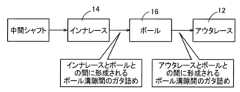
図7は、等速ジョイント10にトルクが入力されたときのトルク伝達経路を示している。インナレース14にスプライン嵌合された不図示の中間シャフトにトルクが入力されると、このトルクがインナレース14に伝達される。次いで、インナレース14の内側ボール溝24とボール16との間に形成されたガタであるボール溝隙間Gapiが詰められ、インナレース14がボール16を押圧する。次いで、ボール16とアウタレース12の外側ボール溝22との間に形成されるガタであるボール溝隙間Gapoが詰められ、ボール16がアウタレース12を押圧する。その結果、アウタレース12にトルクが伝達される。Figure 7 shows the torque transmission path when torque is input to the constant velocity joint 10. When torque is input to an intermediate shaft (not shown) that is spline-fitted to the
上記のように、等速ジョイント10がトルクを伝達するときには、内側ボール溝24とボール16との間のボール溝隙間Gapi、および、ボール16と外側ボール溝22との間のボール溝隙間Gapoが詰められる。ここで、第1溝部30と第2溝部32とで、ボール溝隙間Gapoおよびボール溝隙間Gapi(以下、これらを区別しない場合には各ボール溝隙間Gap)を異ならせると、第1溝部30のボール16と第2溝部32のボール16とで、トルク伝達中にボール16にかかる荷重を異ならせることができる。例えば、特定のボール16のボール溝隙間Gapが大きくなると、他のボール16が先に外側ボール溝22および内側ボール溝24に接触して荷重を受けることとなり、特定のボール16にかかる荷重が小さくなる。従って、ボール溝隙間Gapが大きくなるほど、ボール16にかかる荷重が小さくなる。また、第2溝部32のボール16のロック開放時に発生する異音および振動は、ボール16にかかる荷重が大きくなると発生することから、第2溝部32のボール16にかかる荷重を低減すれば異音および振動が抑制される。As described above, when the constant velocity joint 10 transmits torque, the ball groove gap Gapi between the
上記を考慮して、等速ジョイント10では、等速ジョイント10に入力されるトルクが比較的低い低トルク領域において、第2溝部32のボール16にかかる荷重が第1溝部30のボール16にかかる荷重よりも大きくなるように設定されている。すなわち、前記低トルク領域において、第2溝部32に形成される各ボール溝隙間Gapが、第1溝部30に形成される各ボール溝隙間Gapよりも小さくなるように設定されている。Taking the above into consideration, the constant velocity joint 10 is set so that in the low torque region where the torque input to the constant velocity joint 10 is relatively low, the load applied to the
更に、等速ジョイント10に入力されるトルクが比較的高い高トルク領域において、第2溝部32のボール16にかかる荷重が第1溝部30のボール16にかかる荷重よりも小さくなるように設定されている。すなわち、前記高トルク領域において、第2溝部32の各ボール溝隙間Gapが、第1溝部30の各ボール溝隙間Gapよりも大きくなるように設定されている。Furthermore, in a high torque region where the torque input to the constant velocity joint 10 is relatively high, the load applied to the
具体的には、外側ボール溝22をアウタレース12の中心線CL1に対して垂直な面で切断したときの、第2外側ボール溝22bの円弧の半径である曲率半径Ro2が、第1外側ボール溝22aをアウタレース12の中心線CL1に対して垂直な面で切断したときの、第1外側ボール溝22aの円弧の半径である曲率半径Ro1に比べて大きく形成されている。なお、曲率半径Ro1は、第1外側ボール溝22aをアウタレース12の中心線CL1に沿った方向に見たときの円弧の半径にも相当する。曲率半径Ro2は、第2外側ボール溝22bをアウタレース12の中心線CL1に沿った方向に見たときの円弧の半径にも相当する。Specifically, the radius of curvature Ro2, which is the radius of the arc of the second
又、内側ボール溝24をインナレース14の中心線CL2に対して垂直な面で切断したときの、第2内側ボール溝24bの円弧の半径である曲率半径Ri2が、第1内側ボール溝24aをインナレース14の中心線CL2に対して垂直な面で切断したときの、第1内側ボール溝24aの円弧の半径である曲率半径Ri1に比べて大きく形成されている。なお、曲率半径Ri1は、第1内側ボール溝24aをインナレース14の中心線CL2に沿った方向に見たときの円弧の半径にも相当する。曲率半径Ri2は、第2内側ボール溝24bをインナレース14の中心線CL2に沿った方向に見たときの円弧の半径にも相当する。In addition, the radius of curvature Ri2, which is the radius of the arc of the second
図8に、アウタレース12の外側ボール溝22およびインナレース14の内側ボール溝24の曲率半径Rの関係を示す。図8からもわかるように、アウタレース12において、第2外側ボール溝22bの曲率半径Ro2が、第1外側ボール溝22aの曲率半径Ro1よりも大きく形成されている。また、インナレース14において、第2内側ボール溝24bの曲率半径Ri2が、第1内側ボール溝24aの曲率半径Ri1よりも大きく形成されている。Figure 8 shows the relationship between the radius of curvature R of the outer ball groove 22 of the
上記のように形成されることで、外側ボール溝22の溝底34付近では、第1外側ボール溝22aのボール溝隙間Gapo1が、第2外側ボール溝22bのボール溝隙間Gapo2よりも大きくなる。一方で、外側ボール溝22の溝底34から離れた位置では、第2外側ボール溝22bのボール溝隙間Gapo2が、第1外側ボール溝22aのボール溝隙間Gapo1よりも大きくなる。By forming the gap as described above, the ball groove gap Gapo1 of the first
従って、ボール16が外側ボール溝22の溝底34付近にある場合には、第2外側ボール溝22bのボール16にかかる荷重が、第1外側ボール溝22aのボール16にかかる荷重よりも大きくなる。一方で、ボール16が外側ボール溝22の溝底34から離れた位置にある場合には、第1外側ボール溝22aのボール16にかかる荷重が、第2外側ボール溝22bのボール16にかかる荷重よりも大きくなる。Therefore, when the
また、内側ボール溝24の溝底36付近では、第1内側ボール溝24aのボール溝隙間Gapi1が、第2内側ボール溝24bのボール溝隙間Gapi2よりも大きくなる。一方で、内側ボール溝24の溝底36から離れた位置では、第2内側ボール溝24bのボール溝隙間Gapi2が、第1内側ボール溝24aのボール溝隙間Gapi1よりも大きくなる。In addition, near the
従って、ボール16が内側ボール溝24の溝底36付近にある場合には、第2内側ボール溝24bのボール16にかかる荷重が、第1内側ボール溝24aのボール16にかかる荷重よりも大きくなる。一方で、ボール16が内側ボール溝24の溝底36から離れた位置にある場合には、第1内側ボール溝24aのボール16にかかる荷重が、第2内側ボール溝24bのボール16にかかる荷重よりも大きくなる。Therefore, when the
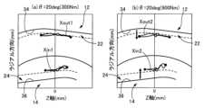
ここで、等速ジョイント10にかかるトルクが大きい場合と小さい場合とで、ボール16と外側ボール溝22および内側ボール溝24との接触点が変化する。図9は、等速ジョイント10にトルクが入力されたときのボール16と外側ボール溝22および内側ボール溝24との接触点の軌跡を示している。図9において、紙面上方が中心線CLを中心とする径方向(ラジアル方向)に対応し、紙面左右方向が中心線CL方向に対応する。また、紙面左側の図9(a)が、ジョイント角θが20度(20deg)であって、等速ジョイント10に入力されるトルクが比較的低トルクである300Nmの状態を示している。紙面右側の図9(b)が、ジョイント角θが20度であって、等速ジョイント10に入力されるトルクが比較的高トルクである900Nmの状態を示している。Here, the contact points between the
図9(a)に示す、ボール16と外側ボール溝22との接触点の軌跡Xout1を、図9(b)に示す、ボール16と外側ボール溝22との接触点の軌跡Xout2と比べると、軌跡Xout2の方が、軌跡Xout1に比べて外側ボール溝22の溝底34から離れた位置で推移している。また、図9(a)に示す、ボール16と内側ボール溝24との接触点の軌跡Xin1を、図9(b)に示す、ボール16と内側ボール溝24との接触点の軌跡Xin2と比べると、軌跡Xin2の方が軌跡Xin1に比べて内側ボール溝24の溝底36から離れた位置で推移している。When comparing the trajectory Xout1 of the contact point between the
従って、等速ジョイント10に入力されるトルクが比較的小さい低トルク領域では、ボール16が外側ボール溝22の溝底34付近で接触するとともに、ボール16が内側ボール溝24の溝底36付近で接触する。また、等速ジョイント10に入力されるトルクが比較的大きい高トルク領域では、ボールが外側ボール溝22の溝底34から離れた位置で接触するとともに、ボール16が内側ボール溝24の溝底36から離れた位置で接触する。Therefore, in the low torque region where the torque input to the constant velocity joint 10 is relatively small, the
上記のように、等速ジョイント10に入力されるトルクが比較的低い低トルク領域では、ボール16が外側ボール溝22の溝底34付近に接触する。このとき、ボール16と第1外側ボール溝22aとの間のボール溝隙間Gapo1が、ボール16と第2外側ボール溝22bとの間のボール溝隙間Gapo2よりも大きくなる。従って、各ボール16にかかる総荷重のうち、第2外側ボール溝22bのボール16が受け持つ荷重(分担荷重)が、第1外側ボール溝22aのボール16が受け持つ荷重(分担荷重)よりも大きくなる。As described above, in the low torque region where the torque input to the constant velocity joint 10 is relatively low, the
また、低トルク領域において、ボール16が内側ボール溝24の溝底36付近で接触する。このとき、ボール16と第1内側ボール溝24aとの間のボール溝隙間Gapi1が、ボール16と第2内側ボール溝24bとの間のボール溝隙間Gapi2よりも大きい為、各ボール16にかかる総荷重のうち、第2内側ボール溝24bのボール16が受け持つ荷重(分担荷重)が、第1内側ボール溝24aのボール16が受け持つ荷重(分担荷重)よりも大きくなる。In addition, in the low torque region, the
上記より、等速ジョイント10に入力されるトルクが比較的低い低トルク領域では、第2溝部32のボール16の分担荷重が、第1溝部30のボール16の分担荷重よりも大きくなる。このとき、第1溝部30のボール16に作用する荷重と、第2溝部32のボール16に作用する荷重とが互いに打ち消し合うことで、トルク伝達効率の高効率化およびアイドル振動の低減という上述した効果が得られる。また、等速ジョイント10に入力されるトルクが比較的低いことから、図6に示す異音や振動も生じない。As described above, in the low torque region where the torque input to the constant velocity joint 10 is relatively low, the load shared by the
また、等速ジョイント10に入力されるトルクが比較的高い高トルク領域において、ボール16が外側ボール溝22の溝底34から離れた位置で接触する。このとき、ボール16と第2外側ボール溝22bとの間のボール溝隙間Gapo2が、ボール16と第1外側ボール溝22aとの間のボール溝隙間Gapo1よりも大きくなる。従って、各ボール16にかかる総荷重のうち、第2外側ボール溝22bのボール16が受け持つ荷重(分担荷重)が、第1外側ボール溝22aのボール16が受け持つ荷重(分担荷重)よりも小さくなる。In addition, in a high torque region where the torque input to the constant velocity joint 10 is relatively high, the
また、高トルク領域において、ボール16が内側ボール溝24の溝底36から離れた位置で接触する。このとき、ボール16と第2内側ボール溝24bとの間のボール溝隙間Gapi2が、ボール16と第1内側ボール溝24aとの間のボール溝隙間Gapi1よりも大きくなる。従って、各ボール16にかかる総荷重のうち、第2内側ボール溝24bのボール16が受け持つ荷重(分担荷重)が、第1内側ボール溝24aのボール16が受け持つ荷重(分担荷重)よりも小さくなる。In addition, in the high torque region, the
上記より、等速ジョイント10に入力されるトルクが比較的高い高トルク領域では、第2溝部32のボール16の分担荷重が、第1溝部30のボール16の分担荷重よりも小さくなる。すなわち、第2外側ボール溝22bおよび第2内側ボール溝24bによって挟まれたボール16にかかる荷重が、第1外側ボール溝22aおよび第1内側ボール溝24aによって挟まれたボール16にかかる荷重よりも小さくなる。従って、第2溝部32における開放角βがゼロ度(0deg)付近になってボール16が一時的にロックしたとき、そのボール16に蓄積されるエネルギが小さくなる。その結果、第2溝部32のボール16のロックが開放されたときに発生する異音および振動が抑制される。As a result, in the high torque region where the torque input to the constant velocity joint 10 is relatively high, the load shared by the
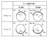
図10は、第1溝部30および第2溝部32の間で、外側ボール溝22および内側ボール溝24の曲率半径Rを異ならすことで得られる効果を纏めた表である。図10に示すように、等速ジョイント10にあっては、低トルク領域において、第1溝部30におけるボール溝隙間Gapo1,Gapi1が、第2溝部32におけるボール溝隙間Gapo2,Gapi2よりも大きくなる。従って、等速ジョイント10において、第2溝部32のボール16の分担荷重が、第1溝部30のボール16の分担荷重よりも大きくなる。この場合には、トルク伝達効率の高効率およびアイドル振動の低減という、等速ジョイント10の本来の効果が得られる。Figure 10 is a table summarizing the effects obtained by making the radius of curvature R of the
また、高トルク領域において、第2溝部32におけるボール溝隙間Gapo2,Gapi2が、第1溝部30におけるボール溝隙間Gapo1,Gapi1よりも大きくなる。従って、等速ジョイント10において、第1溝部30のボール16の分担荷重が、第2溝部32の分担荷重よりも大きくなる。このとき、第2溝部32のボール16にかかる荷重が、第1溝部30のボール16にかかる荷重よりも減少するため、第2溝部32のボール16がロックしたときにボール16に蓄積されるエネルギが減少する。その結果、第2溝部32のボール16が開放されたときに発生する異音および振動(NV)が抑制される。In addition, in the high torque region, the ball groove gaps Gapo2, Gapi2 in the
上述のように、本実施例によれば、第2溝部32を構成するアウタレース12の外側ボール溝22を中心線CL1に対して垂直な面で切断したときの第2外側ボール溝22bの曲率半径Ro2が、第1溝部30を構成する第1外側ボール溝22aの曲率半径Ro1に比べて大きく形成されていると共に、第2溝部32を構成するインナレース14の内側ボール溝24を中心線CL2に対して垂直な面で切断したときの第2内側ボール溝24bの曲率半径Ri2が、第1溝部30を構成する第1内側ボール溝24aの曲率半径Ri1に比べて大きく形成されている為、等速ジョイント10に高トルクがかかり、ボール16にかかる荷重が大きくなる状態下において、第2溝部32側のボール16にかかる荷重を低減することができる。その結果、第2溝部32のボール16のロック開放時に発生する異音および振動を抑制することができる。As described above, according to this embodiment, the radius of curvature Ro2 of the second
また、本実施例によれば、第2溝部32は、ジョイント角θが所定角θ2以上になると、第2溝部32における開放角βがゼロを跨ぐ為、開放角βがゼロを含む範囲において第2溝部32のボール16がロックする。このとき、等速ジョイント10にかかるトルクが高トルクの状態であっても、第2溝部32側のボール16にかかる荷重が低減されることで、第2溝部32のボール16のロック開放時に発生する異音および振動を抑制することができる。In addition, according to this embodiment, when the joint angle θ becomes equal to or greater than the predetermined angle θ2, the opening angle β in the
以上、本発明の実施例を図面に基づいて詳細に説明したが、本発明はその他の態様においても適用される。The above describes in detail an embodiment of the present invention based on the drawings, but the present invention can also be applied in other aspects.
例えば、前述の実施例では、第2溝部32の第2外側ボール溝22bの曲率半径Ro2が、第1溝部30の第1外側ボール溝22aの曲率半径Ro1よりも大きく、且つ、第2溝部32の第2内側ボール溝24bの曲率半径Ri2が、第1溝部30の第1内側ボール溝24aの曲率半径Ri1よりも大きくされていたが、本発明は、必ずしもこの態様に限定されない。具体的には、第2溝部32の第2外側ボール溝22bの曲率半径Ro2が、第1溝部30の第1外側ボール溝22aの曲率半径Ro1よりも大きく形成される、および、第2溝部32の第2内側ボール溝24bの曲率半径Ri2が、第1溝部30の第1内側ボール溝24aの曲率半径Ri1よりも大きく形成される、の何れか一方のみを満たすものであっても構わない。For example, in the above embodiment, the radius of curvature Ro2 of the second
なお、上述したのはあくまでも一実施形態であり、本発明は当業者の知識に基づいて種々の変更、改良を加えた態様で実施することができる。Note that the above is merely one embodiment, and the present invention can be implemented in various forms with various modifications and improvements based on the knowledge of those skilled in the art.
10:等速ジョイント 12:アウタレース 12a:内周面 14:インナレース 14a:外周面 16:ボール 22:外側ボール溝 24:内側ボール溝 30:第1溝部 32:第2溝部 Ri1:曲率半径(第1溝部の内側ボール溝の円弧の半径) Ri2:曲率半径(第2溝部の内側ボール溝の円弧の半径) Ro1:曲率半径(第1溝部の外側ボール溝の円弧の半径) Ro2:曲率半径(第2溝部の外側ボール溝の円弧の半径) θ:ジョイント角 θ2:所定角 α:第1溝部の開放角 β:第2溝部の開放角10: Constant velocity joint 12:
Claims (2)
Translated fromJapanese前記第2溝部を構成する前記アウタレースの前記外側ボール溝を前記アウタレースの中心線に対して垂直な面で切断したときの前記外側ボール溝の円弧の半径が、前記第1溝部を構成する前記外側ボール溝の円弧の半径に比べて大きく形成されている、及び、
前記第2溝部を構成する前記インナレースの前記内側ボール溝を前記インナレースの中心線に対して垂直な面で切断したときの前記内側ボール溝の円弧の半径が、前記第1溝部を構成する前記内側ボール溝の円弧の半径に比べて大きく形成されている、の少なくとも一方を満たす
ことを特徴とする等速ジョイント。 a first groove portion having an opening angle formed by an intersection of a tangent line between the outer ball groove and the ball and a tangent line between the inner ball groove and the ball in a reference state in which the center lines of the outer race and the inner race are aligned in a straight line and a joint angle of zero degree is zero, the first groove portion having an opening angle opening toward a cup opening side of the outer race and a second groove portion having an opening angle opening toward a back side of the cup of the outer race, the second groove portion having an opening angle opening toward a back side of the cup of the outer race, the second groove portion having an opening angle opening toward a back side of the cup of the outer race, the second groove portionhaving an opening angle opening toward a back side of the cup of the outer race, the second groove portion having an opening angle opening toward zero when a joint angle formed by an intersection of the center line of the outer race and the center line of the inner race becomes equal to or greater than a predetermined angle ,
a radius of an arc of the outer ball groove of the outer race constituting the second groove portion when the outer ball groove is cut along a plane perpendicular to a center line of the outer race is larger than a radius of an arc of the outer ball groove constituting the first groove portion; and
a radius of an arc of the inner ball groove of the inner race constituting the second groove portion, when the inner ball groove is cut along a plane perpendicular to a center line of the inner race, is larger than a radius of an arc of the inner ball groove of the first groove portion.
前記第2溝部を構成する前記インナレースの前記内側ボール溝を前記インナレースの中心線に対して垂直な面で切断したときの前記内側ボール溝の円弧の半径が、前記第1溝部を構成する前記内側ボール溝の円弧の半径に比べて大きく形成されている
ことを特徴とする請求項1の等速ジョイント。 when the outer ball groove of the outer race constituting the second groove portion is cut along a plane perpendicular to a center line of the outer race, the radius of the arc of the outer ball groove is larger than the radius of the arc of the outer ball groove constituting the first groove portion,
2. The constant velocity joint according to claim 1, wherein a radius of an arc of the inner ball groove of the inner race constituting the second groove portion when the inner ball groove is cut along a plane perpendicular to a center line of the inner race is larger than a radius of an arc of the inner ball groove constituting the first groove portion.
Priority Applications (3)
| Application Number | Priority Date | Filing Date | Title |
|---|---|---|---|
| JP2022125882AJP7704099B2 (en) | 2022-08-05 | 2022-08-05 | Constant Velocity Joint |
| CN202310889472.6ACN117515054A (en) | 2022-08-05 | 2023-07-19 | Constant velocity joint |
| US18/365,537US20240044376A1 (en) | 2022-08-05 | 2023-08-04 | Constant velocity joint |
Applications Claiming Priority (1)
| Application Number | Priority Date | Filing Date | Title |
|---|---|---|---|
| JP2022125882AJP7704099B2 (en) | 2022-08-05 | 2022-08-05 | Constant Velocity Joint |
Publications (2)
| Publication Number | Publication Date |
|---|---|
| JP2024022360A JP2024022360A (en) | 2024-02-16 |
| JP7704099B2true JP7704099B2 (en) | 2025-07-08 |
Family
ID=89744499
Family Applications (1)
| Application Number | Title | Priority Date | Filing Date |
|---|---|---|---|
| JP2022125882AActiveJP7704099B2 (en) | 2022-08-05 | 2022-08-05 | Constant Velocity Joint |
Country Status (3)
| Country | Link |
|---|---|
| US (1) | US20240044376A1 (en) |
| JP (1) | JP7704099B2 (en) |
| CN (1) | CN117515054A (en) |
Citations (3)
| Publication number | Priority date | Publication date | Assignee | Title |
|---|---|---|---|---|
| DE19722141A1 (en) | 1997-05-27 | 1999-05-06 | Seherr Thoss Graf Von Hans Chr | Homo-kinetic constant speed universal ball joint for constant-speed control and torque transmission |
| JP2011208674A (en) | 2010-03-29 | 2011-10-20 | Ntn Corp | Constant velocity universal joint |
| JP2020118224A (en) | 2019-01-23 | 2020-08-06 | トヨタ自動車株式会社 | Constant velocity universal joint |
Family Cites Families (5)
| Publication number | Priority date | Publication date | Assignee | Title |
|---|---|---|---|---|
| US3553979A (en)* | 1967-12-31 | 1971-01-12 | Toyota Motor Co Ltd | Universal joint of uniform speed |
| US3475924A (en)* | 1968-08-01 | 1969-11-04 | Loehr & Bromkamp Gmbh | Universal joint |
| US7591730B2 (en)* | 2003-08-22 | 2009-09-22 | Gkn Driveline Deutschland Gmbh | Fixed ball joint with turned track cross-sections |
| KR102517733B1 (en)* | 2021-01-07 | 2023-04-05 | 현대위아 주식회사 | Constant velocity joint |
| DE102021208526A1 (en)* | 2021-08-05 | 2023-02-09 | Aktiebolaget Skf | constant velocity joint |
- 2022
- 2022-08-05JPJP2022125882Apatent/JP7704099B2/enactiveActive
- 2023
- 2023-07-19CNCN202310889472.6Apatent/CN117515054A/enactivePending
- 2023-08-04USUS18/365,537patent/US20240044376A1/enactivePending
Patent Citations (3)
| Publication number | Priority date | Publication date | Assignee | Title |
|---|---|---|---|---|
| DE19722141A1 (en) | 1997-05-27 | 1999-05-06 | Seherr Thoss Graf Von Hans Chr | Homo-kinetic constant speed universal ball joint for constant-speed control and torque transmission |
| JP2011208674A (en) | 2010-03-29 | 2011-10-20 | Ntn Corp | Constant velocity universal joint |
| JP2020118224A (en) | 2019-01-23 | 2020-08-06 | トヨタ自動車株式会社 | Constant velocity universal joint |
Also Published As
| Publication number | Publication date |
|---|---|
| JP2024022360A (en) | 2024-02-16 |
| CN117515054A (en) | 2024-02-06 |
| US20240044376A1 (en) | 2024-02-08 |
Similar Documents
| Publication | Publication Date | Title |
|---|---|---|
| US8414404B2 (en) | Damper mechanism | |
| JP7704099B2 (en) | Constant Velocity Joint | |
| US8323116B2 (en) | Universal joint | |
| JP4147179B2 (en) | Constant velocity universal joint | |
| EP1489323B1 (en) | Constant velocity universal joint | |
| JP2006112495A (en) | Uniform joint | |
| JP7120102B2 (en) | vehicle drive shaft | |
| JP2008261391A (en) | Tripod type constant velocity universal joint | |
| JP6274167B2 (en) | Vehicle constant velocity joint | |
| WO2019026596A1 (en) | Spline structure, speed-reducing or speed-increasing device, and constant-velocity joint | |
| JP7188124B2 (en) | constant velocity universal joint | |
| JPH0736184Y2 (en) | Constant velocity universal joint | |
| JP2023111701A (en) | constant velocity joint | |
| JP4935729B2 (en) | Ball type constant velocity joint | |
| JP6887355B2 (en) | Tripod type constant velocity universal joint | |
| JP2012007644A (en) | Sliding tripod constant velocity joint | |
| JP2008019961A (en) | Fixed constant velocity universal joint | |
| JP6904891B2 (en) | Vehicle constant velocity universal joint | |
| US20250146537A1 (en) | Tripod type constant velocity universal joint | |
| JPH0791458A (en) | Propeller shaft for vehicle | |
| US11781599B2 (en) | Constant velocity joint | |
| JP7372858B2 (en) | multi-plate clutch | |
| EP4043755A1 (en) | Transmission | |
| JP4178613B2 (en) | Tripod type constant velocity joint | |
| JP6699476B2 (en) | Constant velocity ball joint |
Legal Events
| Date | Code | Title | Description |
|---|---|---|---|
| A621 | Written request for application examination | Free format text:JAPANESE INTERMEDIATE CODE: A621 Effective date:20240516 | |
| A977 | Report on retrieval | Free format text:JAPANESE INTERMEDIATE CODE: A971007 Effective date:20241226 | |
| A131 | Notification of reasons for refusal | Free format text:JAPANESE INTERMEDIATE CODE: A131 Effective date:20250114 | |
| A521 | Request for written amendment filed | Free format text:JAPANESE INTERMEDIATE CODE: A523 Effective date:20250306 | |
| TRDD | Decision of grant or rejection written | ||
| A01 | Written decision to grant a patent or to grant a registration (utility model) | Free format text:JAPANESE INTERMEDIATE CODE: A01 Effective date:20250527 | |
| A61 | First payment of annual fees (during grant procedure) | Free format text:JAPANESE INTERMEDIATE CODE: A61 Effective date:20250609 | |
| R150 | Certificate of patent or registration of utility model | Ref document number:7704099 Country of ref document:JP Free format text:JAPANESE INTERMEDIATE CODE: R150 |